EP3751212A1 - Indoor unit of air conditioner - Google Patents
Indoor unit of air conditioner Download PDFInfo
- Publication number
- EP3751212A1 EP3751212A1 EP18845338.5A EP18845338A EP3751212A1 EP 3751212 A1 EP3751212 A1 EP 3751212A1 EP 18845338 A EP18845338 A EP 18845338A EP 3751212 A1 EP3751212 A1 EP 3751212A1
- Authority
- EP
- European Patent Office
- Prior art keywords
- angle
- louver
- indoor unit
- louvers
- blow
- Prior art date
- Legal status (The legal status is an assumption and is not a legal conclusion. Google has not performed a legal analysis and makes no representation as to the accuracy of the status listed.)
- Withdrawn
Links
- 238000007664 blowing Methods 0.000 claims abstract description 54
- 238000010438 heat treatment Methods 0.000 claims abstract description 49
- 238000013019 agitation Methods 0.000 claims description 41
- 230000000694 effects Effects 0.000 description 12
- 238000005452 bending Methods 0.000 description 11
- 230000001143 conditioned effect Effects 0.000 description 6
- 239000011810 insulating material Substances 0.000 description 5
- 238000000034 method Methods 0.000 description 4
- 230000007704 transition Effects 0.000 description 4
- 230000003247 decreasing effect Effects 0.000 description 3
- 230000002093 peripheral effect Effects 0.000 description 3
- 239000003507 refrigerant Substances 0.000 description 3
- XLYOFNOQVPJJNP-UHFFFAOYSA-N water Substances O XLYOFNOQVPJJNP-UHFFFAOYSA-N 0.000 description 3
- PPBRXRYQALVLMV-UHFFFAOYSA-N Styrene Chemical compound C=CC1=CC=CC=C1 PPBRXRYQALVLMV-UHFFFAOYSA-N 0.000 description 2
- 238000001816 cooling Methods 0.000 description 2
- 230000007423 decrease Effects 0.000 description 2
- 230000005494 condensation Effects 0.000 description 1
- 238000009833 condensation Methods 0.000 description 1
- 230000008030 elimination Effects 0.000 description 1
- 238000003379 elimination reaction Methods 0.000 description 1
- 230000005855 radiation Effects 0.000 description 1
- 238000005057 refrigeration Methods 0.000 description 1
- 239000011347 resin Substances 0.000 description 1
- 229920005989 resin Polymers 0.000 description 1
- 239000000126 substance Substances 0.000 description 1
Images



Classifications
-
- F—MECHANICAL ENGINEERING; LIGHTING; HEATING; WEAPONS; BLASTING
- F24—HEATING; RANGES; VENTILATING
- F24F—AIR-CONDITIONING; AIR-HUMIDIFICATION; VENTILATION; USE OF AIR CURRENTS FOR SCREENING
- F24F11/00—Control or safety arrangements
- F24F11/70—Control systems characterised by their outputs; Constructional details thereof
- F24F11/72—Control systems characterised by their outputs; Constructional details thereof for controlling the supply of treated air, e.g. its pressure
- F24F11/79—Control systems characterised by their outputs; Constructional details thereof for controlling the supply of treated air, e.g. its pressure for controlling the direction of the supplied air
-
- F—MECHANICAL ENGINEERING; LIGHTING; HEATING; WEAPONS; BLASTING
- F24—HEATING; RANGES; VENTILATING
- F24F—AIR-CONDITIONING; AIR-HUMIDIFICATION; VENTILATION; USE OF AIR CURRENTS FOR SCREENING
- F24F1/00—Room units for air-conditioning, e.g. separate or self-contained units or units receiving primary air from a central station
- F24F1/0007—Indoor units, e.g. fan coil units
- F24F1/0011—Indoor units, e.g. fan coil units characterised by air outlets
- F24F1/0014—Indoor units, e.g. fan coil units characterised by air outlets having two or more outlet openings
-
- F—MECHANICAL ENGINEERING; LIGHTING; HEATING; WEAPONS; BLASTING
- F24—HEATING; RANGES; VENTILATING
- F24F—AIR-CONDITIONING; AIR-HUMIDIFICATION; VENTILATION; USE OF AIR CURRENTS FOR SCREENING
- F24F1/00—Room units for air-conditioning, e.g. separate or self-contained units or units receiving primary air from a central station
- F24F1/0007—Indoor units, e.g. fan coil units
- F24F1/0043—Indoor units, e.g. fan coil units characterised by mounting arrangements
- F24F1/0047—Indoor units, e.g. fan coil units characterised by mounting arrangements mounted in the ceiling or at the ceiling
-
- F—MECHANICAL ENGINEERING; LIGHTING; HEATING; WEAPONS; BLASTING
- F24—HEATING; RANGES; VENTILATING
- F24F—AIR-CONDITIONING; AIR-HUMIDIFICATION; VENTILATION; USE OF AIR CURRENTS FOR SCREENING
- F24F11/00—Control or safety arrangements
- F24F11/50—Control or safety arrangements characterised by user interfaces or communication
- F24F11/56—Remote control
-
- F—MECHANICAL ENGINEERING; LIGHTING; HEATING; WEAPONS; BLASTING
- F24—HEATING; RANGES; VENTILATING
- F24F—AIR-CONDITIONING; AIR-HUMIDIFICATION; VENTILATION; USE OF AIR CURRENTS FOR SCREENING
- F24F13/00—Details common to, or for air-conditioning, air-humidification, ventilation or use of air currents for screening
- F24F13/08—Air-flow control members, e.g. louvres, grilles, flaps or guide plates
-
- F—MECHANICAL ENGINEERING; LIGHTING; HEATING; WEAPONS; BLASTING
- F24—HEATING; RANGES; VENTILATING
- F24F—AIR-CONDITIONING; AIR-HUMIDIFICATION; VENTILATION; USE OF AIR CURRENTS FOR SCREENING
- F24F13/00—Details common to, or for air-conditioning, air-humidification, ventilation or use of air currents for screening
- F24F13/08—Air-flow control members, e.g. louvres, grilles, flaps or guide plates
- F24F13/10—Air-flow control members, e.g. louvres, grilles, flaps or guide plates movable, e.g. dampers
-
- F—MECHANICAL ENGINEERING; LIGHTING; HEATING; WEAPONS; BLASTING
- F24—HEATING; RANGES; VENTILATING
- F24F—AIR-CONDITIONING; AIR-HUMIDIFICATION; VENTILATION; USE OF AIR CURRENTS FOR SCREENING
- F24F13/00—Details common to, or for air-conditioning, air-humidification, ventilation or use of air currents for screening
- F24F13/08—Air-flow control members, e.g. louvres, grilles, flaps or guide plates
- F24F13/10—Air-flow control members, e.g. louvres, grilles, flaps or guide plates movable, e.g. dampers
- F24F13/14—Air-flow control members, e.g. louvres, grilles, flaps or guide plates movable, e.g. dampers built up of tilting members, e.g. louvre
-
- F—MECHANICAL ENGINEERING; LIGHTING; HEATING; WEAPONS; BLASTING
- F24—HEATING; RANGES; VENTILATING
- F24F—AIR-CONDITIONING; AIR-HUMIDIFICATION; VENTILATION; USE OF AIR CURRENTS FOR SCREENING
- F24F13/00—Details common to, or for air-conditioning, air-humidification, ventilation or use of air currents for screening
- F24F13/20—Casings or covers
- F24F2013/207—Casings or covers with control knobs; Mounting controlling members or control units therein
Definitions
- the present invention relates to an indoor unit of an air conditioner having multiple blow ports and including louvers configured to control the wind direction of each blow port, and is specifically suitable as a four-direction ceiling cassette type indoor unit.
- a ceiling cassette type indoor unit having multiple blow ports (e.g., four) and including louvers configured to control the wind direction of each blow port has been known as an indoor unit of a typical air conditioner.
- the louver in the indoor unit of the air conditioner is set to a wind direction set by a user by means of a remote controller, but there is an indoor unit configured such that a louver is forcibly controlled by the indoor unit itself to change a wind direction under a specific operation condition.
- the operation condition includes a condition when the heating operation start-up control of promptly heating the inside of a room at the start of heating, and a condition when the control of improving temperature unevenness between upper and lower portions inside a room in normal heating operation.
- the typical technique of performing the heating operation start-up control as described above includes one described in JP-A-8-320145 .
- an indoor unit an room unit of an air conditioner described in Patent Document 1
- warm air is, at the start of heating operation (upon start-up of the heating operation), directly blown into a living space in a room with a louver angle facing downward, and accordingly, convection heating is performed.
- the inside of the room is heated.
- a louver is swung up and down.
- the wind direction of blown air is controlled to a direction (horizontal blowing) substantially parallel to a ceiling surface such that operation transitions to radiant heating.
- the typical technique of performing the control of improving temperature unevenness between the upper and lower portions in the room in the normal heating operation includes one described in JP-A-2011-196666 (Patent Document 2).
- Patent Document 2 in a case where a temperature uneven state is determined, a temperature unevenness elimination controller starts louver swing action. The swing action is stopped in a case where a predetermined condition is satisfied, and thereafter, a louver is controlled to a downward posture.
- the louver angle is set to a downward direction at the start of heating, and convection heating is performed to heat the inside of the room.
- the louver is swung up and down so that both of the vicinity of the ceiling and the vicinity of a floor surface on which a person is present can be heated.
- the louvers of some blow ports are set to a fully-closed position (a position upon stop of operation) such that a wind velocity at the remaining blow ports is increased.
- a fully-closed position a position upon stop of operation
- indoor environment with a small difference between upper and lower temperatures (small temperature unevenness) is created.
- the louvers are bent due to action of the wind pressure of high-temperature air when the louvers are at the fully-closed position.
- An object of the present invention is to provide an indoor unit of an air conditioner configured so that short circuit can be reduced and bending of a louver can be also prevented.
- the present invention relates to an indoor unit of an air conditioner including a suction port, multiple blow ports provided to surround the periphery of the suction port, and multiple louvers each provided at the blow ports and configured to adjust a blowing direction.
- Each louver is, upon stop of the indoor unit, rotated in the direction of closing the blow port, the angle of each louver rotated in the direction of closing the blow port upon stop of the indoor unit being a fully-closed angle.
- a remote controller configured to set action of each louver upon operation of the indoor unit is provided.
- louver angles of some of the multiple blow ports are, in heating operation, set to a third angle greater than the fully-closed angle as the louver angle upon stop of the indoor unit and smaller than the first angle, and the louvers of the other blow ports are set to automatic swing or downward blowing.
- the indoor unit of the air conditioner configured so that the short circuit can be reduced and bending of the louver can be also prevented can be provided.
- FIG. 1 A first embodiment of an indoor unit of an air conditioner of the present invention will be described with reference to Figs. 1 to 6 .
- Fig. 1 is a perspective view of the indoor unit of the air conditioner of the first embodiment.
- the indoor unit 1 of the air conditioner is configured such that the indoor unit 1 and a not-shown outdoor unit are connected to each other via a refrigerant pipe to form a refrigerant circuit and refrigerant circulates to form a refrigeration cycle.
- the indoor unit 1 is a so-called ceiling cassette type, and includes, for example, a housing 2 embedded in, e.g., a ceiling of a room and a decorative panel 3 provided to close a lower opening of the housing 2.
- the decorative panel 3 includes a suction port 4 provided at the center to suck indoor air, and air blow ports 5 provided at four spots to surround the suction port 4.
- a suction grille 6 is provided at the suction port 4, and a louver 7 configured to adjust the blowing direction of air blown from each blow port 5 is rotatably provided at the blow port 5.
- the louvers 7 illustrated in Fig. 1 indicate a state in which the indoor unit 1 is stopped and the louvers 7 are fully closed, i.e., a state in which a louver angle is a fully-closed angle (0 degree).
- a fully-closed state includes not only a state in which the blow port 5 is fully closed, but also a state in which the louver is substantially horizontal to substantially close the blow port and an opening area is minimum.
- Fig. 2 is a longitudinal sectional view of the indoor unit 1 illustrated in Fig. 1 .
- a motor 8 and a centrifugal fan 9 connected to a rotary shaft of the motor 8 are placed at a center portion in the housing 2.
- the motor 8 is fixed to the center of a top plate of the housing 2.
- a heat exchanger 10 in a hollow square shape as viewed in plane is placed at the periphery of the centrifugal fan 9 to surround the centrifugal fan 9.
- the heat exchanger 10 is a cross fin type fin-and-tube heat exchanger.
- a drain pan 11 configured to receive dew condensation water generated at the heat exchanger 10 is placed below the heat exchanger 10.
- a heat insulating material made of foamed styrol is used as the drain pan 11.
- a water receiving groove is formed along a lower end of the heat exchanger 10, and a lower end portion of the heat exchanger 10 enters the water receiving groove.
- the blow port 5 is formed integrally with the heat insulating material forming the drain pan 11, or is formed from a separate heat insulating material.
- the decorative panel 3 is formed in a square shape slightly larger than the housing 2. Moreover, the decorative panel 3 is arranged along the ceiling 20 to cover a lower surface of the housing 2, and is exposed to an indoor space.
- the louver 7 provided at the blow port 5 of the decorative panel 3 is at a fully-closed position (the louver angle is 0 degree) in Fig. 2 , and indicates a state in which operation of the indoor unit 1 is stopped.
- the louver 7 is rotated to open the blow port 5, and then, is fixed at a predetermined angle set from a remote controller (not shown) by a user, such as downward blowing or lateral blowing (horizontal blowing).
- a remote controller not shown
- the louver 7 performs automatic swing action within a range from the minimum angle to the maximum angle.
- the indoor air is sucked into a suction portion 12 of the centrifugal fan 9 through the suction port 4 and the suction grille 6, and then, is discharged in an outer peripheral direction from a discharge portion 13 of the centrifugal fan 9.
- the air discharged from the centrifugal fan 9 is cooled or heated through the heat exchanger 10. Thereafter, the resultant conditioned air is blown into the room through the blow ports 5 formed at the decorative panel 3 by way of a wind path 14 formed by an outer peripheral surface of the heat exchanger 10 and an inner peripheral surface of the housing 2.
- the louver 7 when the louver 7 is set to an angle for downward blowing, the conditioned air is blown downward.
- the louver 7 is set to an angle for lateral blowing, the conditioned air is blown substantially in a lateral direction (the horizontal direction).
- the louver 7 performs the automatic swing action within the range from the minimum angle to the maximum angle.
- the conditioned air is blown within a range from a direction close to the horizontal direction to a direction close to the vertical direction according to motion of the louver 7.
- 15 is a bell mouth arranged below the centrifugal fan 9 and having, at a center portion, an opening whose diameter gradually decreases while standing toward the suction portion 12 of the centrifugal fan 9.
- the bell mouth 15 is configured to guide air sucked through the suction port 4 to the centrifugal fan 9.
- the bell mouth 15 is configured to divide, together with the drain pan 11, an internal space of the housing 2 into a suction side and a discharge side of the centrifugal fan 9.
- 16 is an electric component box configured to house, e.g., a control board for controlling operation of the indoor unit 1, and the electric component box 16 is placed on a lower surface of the bell mouth 15. 17 is a suction filter placed above the suction grille 6.
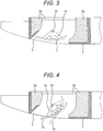
- Fig. 3 is a sectional view of a main portion of one blow port illustrated in Figs. 1 and 2 in a fully-closed angle state of the louver.
- the louver 7 is brought into the fully-closed angle state illustrated in Fig. 3 to prevent a foreign substance from entering the indoor unit during stop of the indoor unit 1 and improve designability upon stop of the indoor unit.
- the fully-closed angle (0 degree) of the louver 7 is not generally a state in which the blow port 5 is fully closed, but a state in which a slight clearance is formed between each of right and left ends of the louver 7 and a wall surface of the decorative panel 3 forming the blow ports 5. It is configured such that the louver 7 and a wall surface of the blow port 5 do not contact each other.
- 3a is a heat insulating material forming the blow port 5, such as foamed styrol.
- the louver 7 is formed in an elongated plate shape or a blade shape extending from one end to the other end of the blow port 5 in a longitudinal direction thereof, and is fixed to a center shaft 18 extending in a longitudinal direction of the louver 7 via an attachment member 19.
- the center shaft 18 is rotatably supported by support members (not shown) arranged on both end sides of the center shaft 18, and rotation of the center shaft 18 is controlled by, e.g., a stepping motor.
- Fig. 4 is a sectional view of a main portion of one blow port illustrated in Figs. 1 and 2 , Fig. 4 being a view of the minimum and maximum angles of the louver during operation of the indoor unit. That is, Fig. 4 illustrates an action range of the louver 7 in a state in which the indoor unit 1 is in operation.
- a louver 7a indicated by a solid line indicates the minimum angle (a first angle) of the louver 7 settable by the user by means of the remote controller (not shown), and a louver 7b indicated by a chain line indicates the maximum angle (a second angle) of the louver 7 settable by the user by means of the remote controller.
- louver 7 When the louver 7 is set to a position 7a at the minimum angle (the first angle), lateral blowing operation for blowing the conditioned air substantially in the horizontal direction from the blow port 5 is performed. On the other hand, when the louver 7 is set to a position 7b at the maximum angle (the second angle), downward blowing operation for blowing the conditioned air substantially in the vertical direction from the blow port 5 is performed.
- the minimum angle (the first angle) is 28 degrees
- the maximum angle (the second angle) is 64 degrees, for example.
- the minimum angle (the first angle) may be set as necessary within a range of about 27 to 30 degrees, for example.
- the maximum angle (the second angle) may be set as necessary within a range of about 60 to 70 degrees, for example.
- the angle of the louver 7 during operation of the indoor unit 1 is not only settable within the range between the minimum angle and the maximum angle from the remote controller, but also is settable from the remote controller at multiple levels in increments of several degrees between the minimum angle and the maximum angle. For example, when the minimum angle is taken as a first level and the maximum angle is taken as a seventh level, five levels (second to sixth levels) of the angle are settable between the first and seventh levels. Note that the angle of the louver 7 is not limited to the seven levels, and more or less levels may be provided. Alternatively, the louver angle may be steplessly settable to an optional angle.
- the louver 7 repeats reciprocation action for increasing the angle from the angle at the start of automatic swing setting such as the first level as the minimum angle to the seventh level as the maximum angle in the order of the second level, the third level, ... and subsequently decreasing the angle to the first level as the minimum angle in the opposite direction in the order of the sixth level, the fifth level, ....
- automatic swing is not limited to the reciprocation action between the first and seventh levels, and for example, may be reciprocation action between the third to seventh levels. Moreover, it may be configured such that upon automatic swing, the louver angle smoothly and steplessly changes.
- louvers of some of four blow ports 5 are set to the fully-closed position (the position upon stop of operation) as illustrated in Fig. 3 such that the wind velocity at the remaining blow ports is increased.
- Fig. 5 is a sectional view of a main portion of one blow port illustrated in Figs. 1 and 2 , Fig. 5 being a view for describing a third louver angle in the first embodiment.
- Fig. 6 is a view for describing action in a state in which the louver illustrated in Fig. 5 is at the third angle.
- the position 7a of the louver 7 indicated by a chain line indicates a case where the louver 7 is set to the position at the minimum angle (the first angle)
- the position 7b of the louver 7 similarly indicated by a chain line indicates a case where the louver 7 is set to the position at the maximum angle (the second angle).
- These positions 7a, 7b of the louver 7 are the angles of the louver 7 settable from the remote controller (not shown), and are functions generally provided to the typical indoor unit.
- the function of automatically swinging the louver 7 within the range between the first angle position 7a and the second angle position is also generally provided, and is settable from the remote controller.
- the present embodiment is configured such that the angle of the louver 7 of each of four blow ports 5 illustrated in Fig. 1 is, as illustrated in Fig. 5 , settable to a position 7c at the third angle greater than the fully-closed angle (a louver angle of 0 degree) as the louver angle upon stop of the indoor unit as illustrated in Fig. 3 and smaller than the first angle as the minimum opening degree of the louver 7 settable from the remote controller.
- the position 7c at the third angle of the louver 7 is not an angle settable by the user from the remote controller, but the angle position of the louver 7 automatically set from a control device (not shown) included in, e.g., the indoor unit 1 of the air conditioner in the case of a preset predetermined operation condition such as the start of the heating operation.
- the third angle is set to an angle, such as 14 degrees, greater than 0 degree as the fully-closed angle upon stop of the indoor unit and smaller than the first angle (28 degrees) as the minimum angle settable by the user from the remote controller.
- the third angle is not limited to 14 degrees, and may be set as necessary within a range of 5 to 25 degrees and preferably a range of 10 to 18 degrees.
- the third angle corresponds to an angle of a 0.5 level.
- the angle of the 0.5 level is not a louver angle settable by the user from the remote controller, but is an angle automatically set from the control device provided at, e.g., the indoor unit 1 in the case of the predetermined operation condition.
- each louver 7 is settable to the position 7c at the third angle (the angle of the 0.5 level) as described above.
- the louvers 7 of some blow ports 5 among the louvers 7 of the multiple blow ports 5 are set to the position 7c at the third angle.
- the louvers 7 of some blow ports 5 are set to the position at the third angle (the angle greater than the fully-closed angle of the louver and smaller than the first angle) so that a small clearance 21 can be formed between the wall surface of the blow port 5 and an end portion of the louver 7 as indicated by a hatched circle in Fig. 6 .
- a small clearance 21 can be formed between the wall surface of the blow port 5 and an end portion of the louver 7 as indicated by a hatched circle in Fig. 6 .
- an air flow can be blown from the clearance 21, and therefore, bending of the louver due to the wind pressure can be reduced.
- bending of the louver 7 can be suppressed small, and therefore, plastic deformation of the louver can be reduced even in a case where high-temperature air is blown into the room.
- louvers 7 set to the third angle may be configured switchable sequentially in every predetermined time. Moreover, for the louvers 7 of the other blow ports 5, louver action settable from the remote controller is performed. That is, the other louvers 7 are set to automatic swing, or are set to an optional louver angle.
- the preset predetermined operation condition of the air conditioner includes, for example, operation conditions as follows, and it may be configured such that the louvers of some blow ports among the louvers of the multiple blow ports are automatically set to the third angle from the control device (not shown) provided at, e.g., the indoor unit 1 in a case where the following operation is performed:
- the user cannot set an optional louver to the third angle from the remote controller, but the third angle is the angle automatically set from the control device of the air conditioner in a case where, e.g., the high-speed blowing setting has been made.
- the angle of the louver 7 of any of the blow ports 5 is automatically set to the third angle position from the control device.
- the opening area of the blow port 5 of the louver portion set to the third angle is decreased.
- the volume of wind blown from the blow port 5 can be significantly reduced, and the velocity of wind blown from the other blow ports 5 can be sufficiently increased. Consequently, sufficient blown air can reach a far position such as the floor surface.
- the small clearance 21 can be formed between the wall surface of the blow port 5 and the end portion of the louver 7, and therefore, an air flow can be blown from the clearance 21.
- bending of the louver 7 due to the wind pressure can be reduced.
- the rotation speed of the centrifugal fan 9 is increased, and therefore, bending of the louver 7 can be reduced even in a case where a great volume of high-temperature air is blown into the room. Consequently, plastic deformation of the louver 7 can be also reduced.
- the angles of the louvers 7 of some of the multiple blow ports 5 are not promptly controlled to the third angle, but may be first held at the fully-closed angle for such predetermined time that plastic deformation of the louvers 7 does not occur and be subsequently controlled to the third angle after a lapse of the predetermined time.
- the velocity of wind blown from the other blow ports 5 can be further increased as compared to the case of control to the third angle when the louvers 7 are held at the fully-closed angle, and therefore, a high-speed blowing effect can be further improved.
- the louvers 7 controlled to the fully-closed angle are controlled to the third angle before plastic deformation of the louvers 7 occurs, and therefore, the effect of preventing plastic deformation of the louvers 7 can be also provided.
- the minimum angle settable by the remote controller is taken as the first angle
- the louver angle greater than the fully-closed angle as the louver angle upon stop of the indoor unit and smaller than the first angle is taken as the third angle.
- the minimum angle of the louver upon automatic swing may be taken as the first angle
- the louver angle greater than the fully-closed angle as the louver angle upon stop of the indoor unit and smaller than the first angle may be set as the third angle.
- the angles of the louvers 7 of some of the multiple blow ports 5 are set to the third angle greater than the fully-closed angle (0 degree) as the louver angle upon stop of the indoor unit and smaller than the first angle as the minimum angle settable from the remote controller or the minimum angle upon automatic swing, and the louvers 7 of the other blow ports are set to the second angle or automatic swing.
- Fig. 7 is a table for describing the louver action in start-up operation and subsequent agitation operation in the indoor unit of the typical air conditioner
- Fig. 8 is a view for describing a short circuit phenomenon in a case where all louvers are brought into downward blowing in the start-up operation and the subsequent agitation operation in Fig. 7
- Fig. 9 is a table for describing the louver action in start-up operation and the subsequent agitation operation in the indoor unit of the air conditioner of the first embodiment
- Fig. 10 is a view for describing the louver action in the agitation operation illustrated in Fig. 9 , a blown air flow, and a sucked air flow.
- louvers 7A to 7D of four blow ports 5 illustrated in Fig. 1 are, as illustrated in Fig. 7 , controlled to the second angle (downward blowing), i.e., the maximum angle, in the start-up operation for the heating operation. Thereafter, all of the louvers 7A to 7D perform the automatic swing action after a lapse of predetermined time, and the agitation operation is performed. Note that the agitation operation is performed for predetermined time, and normal operation is brought subsequently.
- Fig. 8 24 indicates the flow of cool indoor air sucked into the suction port 4 of the indoor unit 1 from the vicinity of the floor surface F forming the indoor space R.
- the indoor unit of the air conditioner of the first embodiment in which the above-described problems of the indoor unit of the typical air conditioner have been solved will be described with reference to Figs. 9 and 10 .
- the louvers 7A to 7D of four blow ports 5 illustrated in Fig. 1 are controlled as illustrated in Fig. 9 in the first embodiment.
- control is the same as that illustrated in Fig. 7 on a point that the wind directions of the louvers 7A to 7D of all of four blow ports 5 are simultaneously controlled to the second angle (downward blowing) in the heating start-up operation.
- a difference of the indoor unit 1 of the first embodiment from that of the typical case illustrated in Figs. 7 and 8 is control of the louvers 7Ato 7D in the agitation operation performed after a lapse of the predetermined time in the heating start-up operation.
- the louvers 7B to 7D of three blow ports 5 among the louvers 7 of four blow ports 5 perform the automatic swing action to perform the agitation operation, but the louver 7A of the blow port 5 as one of the louvers 7 of four blow ports 5 is, as illustrated in Fig. 9 , controlled to the third angle (blowing beyond the horizontal direction) described with reference to Fig. 5 .
- the third angle is the angle (the angle of the 0.5 level) greater than the fully-closed angle (a louver angle of 0 degree) as the louver angle upon stop of the indoor unit as illustrated in Fig. 3 and smaller than the first angle (the angle of the first level) as the minimum opening degree of the louver 7 settable from the remote controller, and is an angle such as 14 degrees.
- the position 7c of the louver 7 at the third angle is not the angle settable by the user from the remote controller, but the angle position of the louver 7 automatically set from the control device included at, e.g., the indoor unit 1 of the air conditioner under the preset predetermined operation condition.
- louvers 7A to 7D perform the automatic swing action in the agitation operation.
- all of four louvers 7Ato 7D face downward during the automatic swing action.
- the louver 7A of the single blow port 5 is set to the third angle (blowing beyond the horizontal direction), and therefore, the following advantageous effects are provided.
- the louver 7A is set to the position at the third angle, and therefore, the small clearance 21 can be formed between the wall surface of the blow port 5 and the end portion of the louver 7 as indicated by the hatched circle in Fig. 6 .
- the air flow can be blown from the clearance 21, and therefore, bending of the louver 7A due to the wind pressure can be reduced.
- the effect of reducing plastic deformation of the louver even in a case where high-temperature air is blown into the room can be provided.
- the effect of providing the indoor unit of the air conditioner configured so that the short circuit can be reduced and bending of the louver can be also reduced is provided. Moreover, high-speed blowing from the blow ports 5 having the louvers other than the louvers set to the third angle is allowed.
- action in the heating start-up operation illustrated in Fig. 9 is for a case where the user sets, e.g., a high-load heating mode.
- the air conditioner automatically performs action of the heating start-up operation illustrated in Fig. 9 .
- the start-up operation is performed for the predetermined time such as 30 minutes, and subsequently transitions to the agitation operation.
- the agitation operation is performed for about 10 minutes, and subsequently transitions to the normal operation freely settable by the user from the remote controller.
- a second embodiment of an indoor unit of an air conditioner of the present invention will be described with reference to Fig. 11 .
- a basic configuration of the indoor unit 1 is similar to that of the first embodiment described with reference to Figs. 1 to 6 and 10 , and therefore, description of similar elements will be omitted. Differences of the second embodiment from the first embodiment will be mainly described.
- Fig. 11 is a table for describing louver action in start-up operation and subsequent agitation operation in the second embodiment of the indoor unit of the air conditioner.
- control is the same as that illustrated in Fig. 7 on a point that the wind directions of louvers 7A to 7D of all of four blow ports 5 are simultaneously controlled to a second angle (downward blowing) in heating start-up operation.
- a difference of the indoor unit 1 of the second embodiment from that of the first embodiment is control of the louvers 7A to 7D in the agitation operation performed after a lapse of predetermined time in the heating start-up operation as illustrated in Fig. 11 .
- the louvers 7B to 7D of three blow ports 5 among the louvers 7 of four blow ports 5 first perform automatic swing action to perform the agitation operation.
- the louver 7A of the blow port 5 as one of the louvers 7 of four blow ports 5 is controlled to a third angle (blowing beyond the horizontal direction) as in Fig. 9 .
- the louver 7A is controlled to the third angle for preset certain time. Thereafter, the louvers 7A, 7C, 7D of three blow ports 5 among the louvers 7 of four blow ports 5 perform the automatic swing action to perform the agitation operation, and the louver 7B of the blow port 5 as one of the louvers 7 of four blow ports 5 is controlled and fixed to the third angle (blowing beyond the horizontal direction).
- the louvers 7A, 7B, 7D of three blow ports 5 next perform the automatic swing action to perform the agitation operation, and the louver 7C is controlled and fixed to the third angle (blowing beyond the horizontal direction).
- the louvers 7A to 7C of three blow ports 5 next perform the automatic swing action to perform the agitation operation, and the louver 7D is controlled and fixed to the third angle (blowing beyond the horizontal direction).
- similar action is repeated in every certain time to perform the agitation operation. Note that after completion, the agitation operation transitions to normal operation.
- the louver set to the third angle is sequentially controlled and switched in every certain time in the agitation operation as illustrated in Fig. 11 , and therefore, the following advantageous effects are provided.
- the configuration of the second embodiment provides the effect of reducing unevenness in an indoor temperature.
- FIG. 12 is a table for describing louver action in start-up operation and subsequent agitation operation in the third embodiment of the indoor unit of the air conditioner. Note that a basic configuration of the indoor unit 1 is similar to that of the first embodiment described with reference to Figs. 1 to 6 and 10 , and therefore, description of similar elements will be omitted. Differences of the third embodiment from the first embodiment will be mainly described.
- the wind directions of some louvers 7A, 7C are simultaneously controlled to a second angle (downward blowing) in heating start-up operation, and the other louvers 7B, 7D are controlled to a third angle (blowing beyond the horizontal direction).
- control of the louvers 7A to 7D in the agitation operation performed after a lapse of predetermined time in the heating start-up operation is similar to that of the first embodiment described with reference to Fig. 9 . That is, in the third embodiment, when the agitation operation begins, the louvers 7B to 7D of three blow ports 5 among the louvers 7 of four blow ports 5 perform automatic swing action to perform the agitation operation, and the louver 7A of the blow port 5 as one of the louvers 7 of four blow ports 5 is controlled to the third angle (blowing beyond the horizontal direction) as illustrated in Fig. 12 .
- louvers 7B, 7D are controlled to the third angle.
- the effect of allowing such high-speed blowing that the velocity of wind blown downward from the other louvers 7A, 7C is further increased and promptly increasing the surrounding temperature of a person in an indoor space is provided.
- the louvers 7B, 7D are controlled to the third angle, and therefore, a sucked air passage 25 (see Fig. 10 ) is formed below the blow ports 5 including the louvers 7B, 7D, and cool air at a lower portion in the indoor space R is easily sucked into a suction port 4 of the indoor unit 1.
- a short circuit phenomenon described with reference to Fig. 8 can be also reduced.
- control of the louvers 7A to 7D in the agitation operation performed after a lapse of the predetermined time in the heating start-up operation can reduce the short circuit and uniformly heat air across the entirety of the indoor space as in the first embodiment illustrated in Fig. 9 .
- louvers are controlled to the third angle.
- bending of the louver due to a wind pressure can be reduced, and plastic deformation of the louver can be reduced even in a case where high-temperature air is blown into a room.
- louvers 7B, 7D are controlled to the third angle in the heating start-up operation.
- the louvers controlled to the third angle may be 7A, 7C, or only any one of four louvers may be controlled to the third angle.
- the example where the louver 7A is controlled to the third angle in the agitation operation has been described.
- any one of four louvers may be, as the louver controlled to the third angle, controlled to the third angle, or it may be configured such that optional multiple louvers are controlled to the third angle.
- the louver angles of some of the multiple blow ports are, in the heating operation, set to the third angle greater than the fully-closed angle and smaller than the first angle as the minimum angle settable from the remote controller, and the louvers of the other blow ports are set to downward blowing or automatic swing.
- the louvers other than the louvers set to the third angle are simultaneously set to the second angle as the maximum angle settable from the remote controller, the passage for sucking the indoor air (cool air) can be ensured below each louver controlled to the third angle, and therefore, the short circuit can be reduced.
- the louvers of some of the multiple blow ports are set to the third angle.
- the velocity of wind blown from the other blow ports can be increased. Consequently, the surrounding temperature of the person in the indoor space can be promptly increased, and the agitation operation can be efficiently performed.
- action of the wind pressure of high-temperature air on the louvers set to the third angle can be reduced, and therefore, the effect of reducing bending and plastic deformation of the louvers is provided.
- the present invention is not limited to the above-described embodiments, and includes variations.
- the example where all louvers are set to the second angle (downward blowing) or some louvers are set to the third angle (blowing beyond the horizontal direction) in the heating start-up operation has been described.
- it may be configured such that all louvers are set to automatic swing or some louvers are set to the third angle and the other louvers perform automatic swing.
Landscapes
- Engineering & Computer Science (AREA)
- Chemical & Material Sciences (AREA)
- Combustion & Propulsion (AREA)
- Mechanical Engineering (AREA)
- General Engineering & Computer Science (AREA)
- Human Computer Interaction (AREA)
- Air Conditioning Control Device (AREA)
Abstract
Description
- The present invention relates to an indoor unit of an air conditioner having multiple blow ports and including louvers configured to control the wind direction of each blow port, and is specifically suitable as a four-direction ceiling cassette type indoor unit.
- A ceiling cassette type indoor unit having multiple blow ports (e.g., four) and including louvers configured to control the wind direction of each blow port has been known as an indoor unit of a typical air conditioner.
- Typically, the louver in the indoor unit of the air conditioner is set to a wind direction set by a user by means of a remote controller, but there is an indoor unit configured such that a louver is forcibly controlled by the indoor unit itself to change a wind direction under a specific operation condition. For example, the operation condition includes a condition when the heating operation start-up control of promptly heating the inside of a room at the start of heating, and a condition when the control of improving temperature unevenness between upper and lower portions inside a room in normal heating operation.
- The typical technique of performing the heating operation start-up control as described above includes one described in
JP-A-8-320145 Patent Document 1, warm air is, at the start of heating operation (upon start-up of the heating operation), directly blown into a living space in a room with a louver angle facing downward, and accordingly, convection heating is performed. In this manner, the inside of the room is heated. Then, when a difference between an indoor temperature and a set temperature falls within a predetermined value, a louver is swung up and down. Further, after a lapse of predetermined time, the wind direction of blown air is controlled to a direction (horizontal blowing) substantially parallel to a ceiling surface such that operation transitions to radiant heating. - With this configuration, lowering of the indoor temperature can be effectively suppressed while comfortable heating can be performed due to radiation heat of warm air in the vicinity of a ceiling such that a resident in the room does not feel a warm air flow.
- Moreover, the typical technique of performing the control of improving temperature unevenness between the upper and lower portions in the room in the normal heating operation includes one described in
JP-A-2011-196666 Patent Document 2, in a case where a temperature uneven state is determined, a temperature unevenness elimination controller starts louver swing action. The swing action is stopped in a case where a predetermined condition is satisfied, and thereafter, a louver is controlled to a downward posture. -
- Patent Document 1:
JP-A-8-320145 - Patent Document 2:
JP-A-2011-196666 - In
Patent Document 1, the louver angle is set to a downward direction at the start of heating, and convection heating is performed to heat the inside of the room. When the difference between the indoor temperature and the set temperature falls within the predetermined value, the louver is swung up and down so that both of the vicinity of the ceiling and the vicinity of a floor surface on which a person is present can be heated. - Moreover, in
Patent Document 2, when the temperature uneven state is brought, the louver swing action is started. When the predetermined condition is satisfied, the swing action is stopped, and the louver is controlled to the downward posture. In this manner, temperature unevenness is reduced. - However, in the case of an indoor unit of an air conditioner including multiple (e.g., four) blow ports provided to surround a suction port, when all louvers are set to a downward direction or upper-to-lower swing action is performed for all louvers in heating operation, a state in which the wind directions of all blow ports simultaneously become downward blowing is brought. When the wind directions of all blow ports simultaneously become downward blowing, a phenomenon that blown air is sucked into the suction port before expanding across an indoor space, i.e., short circuit, easily occurs. Thus, there is a problem that a heating capacity is lowered.
- Moreover, a case where a sucked air temperature sensor is placed at the suction port is typical. However, when the short circuit occurs, blown air contacts the suction temperature sensor. Due to such contact, the sucked air temperature sensor senses a higher temperature than an actual indoor air temperature. Thus, there is a problem that unnecessary stop of heating (thermo-off) occurs.
- Note that in the indoor unit including four blow ports, the louvers of some blow ports are set to a fully-closed position (a position upon stop of operation) such that a wind velocity at the remaining blow ports is increased. In this manner, indoor environment with a small difference between upper and lower temperatures (small temperature unevenness) is created. However, there is a problem that the louvers are bent due to action of the wind pressure of high-temperature air when the louvers are at the fully-closed position.
- An object of the present invention is to provide an indoor unit of an air conditioner configured so that short circuit can be reduced and bending of a louver can be also prevented.
- For accomplishing the above-described object, the present invention relates to an indoor unit of an air conditioner including a suction port, multiple blow ports provided to surround the periphery of the suction port, and multiple louvers each provided at the blow ports and configured to adjust a blowing direction. Each louver is, upon stop of the indoor unit, rotated in the direction of closing the blow port, the angle of each louver rotated in the direction of closing the blow port upon stop of the indoor unit being a fully-closed angle. A remote controller configured to set action of each louver upon operation of the indoor unit is provided. When the minimum angle among louver angles settable by the remote controller is taken as a first angle and the maximum angle is taken as a second angle, the louver angles of some of the multiple blow ports are, in heating operation, set to a third angle greater than the fully-closed angle as the louver angle upon stop of the indoor unit and smaller than the first angle, and the louvers of the other blow ports are set to automatic swing or downward blowing.
- According to the present invention, there is an advantageous effect that the indoor unit of the air conditioner configured so that the short circuit can be reduced and bending of the louver can be also prevented can be provided.
-
-
Fig. 1 is a perspective view of a first embodiment of an indoor unit of an air conditioner of the present invention. -
Fig. 2 is a longitudinal sectional view of the indoor unit illustrated inFig. 1 . -
Fig. 3 is a sectional view of a main portion of one blow port illustrated inFigs. 1 and 2 in a fully-closed state of a louver. -
Fig. 4 is a sectional view of a main portion of one blow port illustrated inFigs. 1 and 2 ,Fig. 4 being a view of the minimum angle (a first angle) and the maximum angle (a second angle) of the louver during operation of the indoor unit. -
Fig. 5 is a sectional view of a main portion of one blow port illustrated inFigs. 1 and 2 ,Fig. 5 being a view for describing a third louver angle in the first embodiment. -
Fig. 6 is a view for describing action when the louver illustrated inFig. 5 is in a third angle state. -
Fig. 7 is a table for describing louver action in start-up operation and subsequent agitation operation in an indoor unit of a typical air conditioner. -
Fig. 8 is a view for describing a short circuit phenomenon in a case where all louvers are set to downward blowing in the start-up operation and the subsequent agitation operation inFig. 7 . -
Fig. 9 is a table for describing louver action in start-up operation and subsequent agitation operation in the first embodiment of the indoor unit of the air conditioner. -
Fig. 10 is a view for describing the louver action in the agitation operation illustrated inFig. 9 , a blown air flow, and a sucked air flow. -
Fig. 11 is a table for describing louver action in start-up operation and subsequent agitation operation in a second embodiment of the indoor unit of the air conditioner. -
Fig. 12 is a table for describing louver action in start-up operation and subsequent agitation operation in a third embodiment of the indoor unit of the air conditioner. - Hereinafter, specific embodiments of the present invention will be described with reference to the drawings. In each figure, the same reference numerals are used to represent the same or equivalent elements.
- A first embodiment of an indoor unit of an air conditioner of the present invention will be described with reference to
Figs. 1 to 6 . - First, an entire configuration of the indoor unit of the air conditioner in the first embodiment will be described with reference to
Fig. 1. Fig. 1 is a perspective view of the indoor unit of the air conditioner of the first embodiment. - As illustrated in
Fig. 1 , theindoor unit 1 of the air conditioner is configured such that theindoor unit 1 and a not-shown outdoor unit are connected to each other via a refrigerant pipe to form a refrigerant circuit and refrigerant circulates to form a refrigeration cycle. Theindoor unit 1 is a so-called ceiling cassette type, and includes, for example, ahousing 2 embedded in, e.g., a ceiling of a room and adecorative panel 3 provided to close a lower opening of thehousing 2. Thedecorative panel 3 includes asuction port 4 provided at the center to suck indoor air, andair blow ports 5 provided at four spots to surround thesuction port 4. - A suction grille 6 is provided at the
suction port 4, and alouver 7 configured to adjust the blowing direction of air blown from eachblow port 5 is rotatably provided at theblow port 5. Note that thelouvers 7 illustrated inFig. 1 indicate a state in which theindoor unit 1 is stopped and thelouvers 7 are fully closed, i.e., a state in which a louver angle is a fully-closed angle (0 degree). A fully-closed state includes not only a state in which theblow port 5 is fully closed, but also a state in which the louver is substantially horizontal to substantially close the blow port and an opening area is minimum. -
Fig. 2 is a longitudinal sectional view of theindoor unit 1 illustrated inFig. 1 . As illustrated inFig. 2 , amotor 8 and acentrifugal fan 9 connected to a rotary shaft of themotor 8 are placed at a center portion in thehousing 2. Themotor 8 is fixed to the center of a top plate of thehousing 2. - Moreover, a
heat exchanger 10 in a hollow square shape as viewed in plane is placed at the periphery of thecentrifugal fan 9 to surround thecentrifugal fan 9. Theheat exchanger 10 is a cross fin type fin-and-tube heat exchanger. Moreover, adrain pan 11 configured to receive dew condensation water generated at theheat exchanger 10 is placed below theheat exchanger 10. Generally, a heat insulating material made of foamed styrol is used as thedrain pan 11. A water receiving groove is formed along a lower end of theheat exchanger 10, and a lower end portion of theheat exchanger 10 enters the water receiving groove. Moreover, although not shown in the figure, theblow port 5 is formed integrally with the heat insulating material forming thedrain pan 11, or is formed from a separate heat insulating material. - 20 is the ceiling of the room, and the
indoor unit 1 is placed such that ahousing 2 portion is embedded in theceiling 20. Thedecorative panel 3 is formed in a square shape slightly larger than thehousing 2. Moreover, thedecorative panel 3 is arranged along theceiling 20 to cover a lower surface of thehousing 2, and is exposed to an indoor space. - The
louver 7 provided at theblow port 5 of thedecorative panel 3 is at a fully-closed position (the louver angle is 0 degree) inFig. 2 , and indicates a state in which operation of theindoor unit 1 is stopped. When theindoor unit 1 starts operating, thelouver 7 is rotated to open theblow port 5, and then, is fixed at a predetermined angle set from a remote controller (not shown) by a user, such as downward blowing or lateral blowing (horizontal blowing). Alternatively, when the user sets action of thelouver 7 to automatic swing from the remote controller, thelouver 7 performs automatic swing action within a range from the minimum angle to the maximum angle. - Moreover, when operation of the
indoor unit 1 begins, the indoor air is sucked into asuction portion 12 of thecentrifugal fan 9 through thesuction port 4 and the suction grille 6, and then, is discharged in an outer peripheral direction from adischarge portion 13 of thecentrifugal fan 9. The air discharged from thecentrifugal fan 9 is cooled or heated through theheat exchanger 10. Thereafter, the resultant conditioned air is blown into the room through theblow ports 5 formed at thedecorative panel 3 by way of awind path 14 formed by an outer peripheral surface of theheat exchanger 10 and an inner peripheral surface of thehousing 2. - At this point, when the
louver 7 is set to an angle for downward blowing, the conditioned air is blown downward. When thelouver 7 is set to an angle for lateral blowing, the conditioned air is blown substantially in a lateral direction (the horizontal direction). Further, in the case of setting to automatic swing as described above, thelouver 7 performs the automatic swing action within the range from the minimum angle to the maximum angle. Thus, the conditioned air is blown within a range from a direction close to the horizontal direction to a direction close to the vertical direction according to motion of thelouver 7. - Note that in
Fig. 2 , 15 is a bell mouth arranged below thecentrifugal fan 9 and having, at a center portion, an opening whose diameter gradually decreases while standing toward thesuction portion 12 of thecentrifugal fan 9. Thebell mouth 15 is configured to guide air sucked through thesuction port 4 to thecentrifugal fan 9. Moreover, thebell mouth 15 is configured to divide, together with thedrain pan 11, an internal space of thehousing 2 into a suction side and a discharge side of thecentrifugal fan 9. - 16 is an electric component box configured to house, e.g., a control board for controlling operation of the
indoor unit 1, and theelectric component box 16 is placed on a lower surface of thebell mouth 15. 17 is a suction filter placed above the suction grille 6. - Next, a configuration of the vicinity of the
louver 7 in the fully-closed state of thelouver 7, i.e., the state in which thelouver 7 is at the fully-closed angle (0 degree), will be described with reference toFig. 3. Fig. 3 is a sectional view of a main portion of one blow port illustrated inFigs. 1 and 2 in a fully-closed angle state of the louver. When operation of theindoor unit 1 is stopped, thelouver 7 is brought into the fully-closed angle state illustrated inFig. 3 to prevent a foreign substance from entering the indoor unit during stop of theindoor unit 1 and improve designability upon stop of the indoor unit. - As illustrated in
Fig. 3 , the fully-closed angle (0 degree) of thelouver 7 is not generally a state in which theblow port 5 is fully closed, but a state in which a slight clearance is formed between each of right and left ends of thelouver 7 and a wall surface of thedecorative panel 3 forming theblow ports 5. It is configured such that thelouver 7 and a wall surface of theblow port 5 do not contact each other. - Note that in
Fig. 3 , 3a is a heat insulating material forming theblow port 5, such as foamed styrol. - As illustrated in
Fig. 1 , thelouver 7 is formed in an elongated plate shape or a blade shape extending from one end to the other end of theblow port 5 in a longitudinal direction thereof, and is fixed to acenter shaft 18 extending in a longitudinal direction of thelouver 7 via anattachment member 19. Thecenter shaft 18 is rotatably supported by support members (not shown) arranged on both end sides of thecenter shaft 18, and rotation of thecenter shaft 18 is controlled by, e.g., a stepping motor. -
Fig. 4 is a sectional view of a main portion of one blow port illustrated inFigs. 1 and 2 ,Fig. 4 being a view of the minimum and maximum angles of the louver during operation of the indoor unit. That is,Fig. 4 illustrates an action range of thelouver 7 in a state in which theindoor unit 1 is in operation. Alouver 7a indicated by a solid line indicates the minimum angle (a first angle) of thelouver 7 settable by the user by means of the remote controller (not shown), and alouver 7b indicated by a chain line indicates the maximum angle (a second angle) of thelouver 7 settable by the user by means of the remote controller. - When the
louver 7 is set to aposition 7a at the minimum angle (the first angle), lateral blowing operation for blowing the conditioned air substantially in the horizontal direction from theblow port 5 is performed. On the other hand, when thelouver 7 is set to aposition 7b at the maximum angle (the second angle), downward blowing operation for blowing the conditioned air substantially in the vertical direction from theblow port 5 is performed. - Note that in the present embodiment, when the fully-closed angle as the louver angle upon stop of the
indoor unit 1 as illustrated inFig. 3 is 0 degree, the minimum angle (the first angle) is 28 degrees, and the maximum angle (the second angle) is 64 degrees, for example. Note that the minimum angle (the first angle) may be set as necessary within a range of about 27 to 30 degrees, for example. Moreover, the maximum angle (the second angle) may be set as necessary within a range of about 60 to 70 degrees, for example. - The angle of the
louver 7 during operation of theindoor unit 1 is not only settable within the range between the minimum angle and the maximum angle from the remote controller, but also is settable from the remote controller at multiple levels in increments of several degrees between the minimum angle and the maximum angle. For example, when the minimum angle is taken as a first level and the maximum angle is taken as a seventh level, five levels (second to sixth levels) of the angle are settable between the first and seventh levels. Note that the angle of thelouver 7 is not limited to the seven levels, and more or less levels may be provided. Alternatively, the louver angle may be steplessly settable to an optional angle. - When action of the
louver 7 is set to automatic swing from the remote controller, thelouver 7 repeats reciprocation action for increasing the angle from the angle at the start of automatic swing setting such as the first level as the minimum angle to the seventh level as the maximum angle in the order of the second level, the third level, ... and subsequently decreasing the angle to the first level as the minimum angle in the opposite direction in the order of the sixth level, the fifth level, .... - Note that automatic swing is not limited to the reciprocation action between the first and seventh levels, and for example, may be reciprocation action between the third to seventh levels. Moreover, it may be configured such that upon automatic swing, the louver angle smoothly and steplessly changes.
- In the indoor unit of the air conditioner as described above, in high-load operation in which a temperature difference between an external air temperature and a room temperature is extremely great in, e.g., heating operation, a wind direction is set to downward blowing such that warm air is supplied downward. However, in some cases, sufficient blown air cannot reach a floor surface.
- Moreover, another technique for decreasing the opening area of the
blow port 5 of theindoor unit 1 is conceivable, in which the louvers of some of fourblow ports 5 are set to the fully-closed position (the position upon stop of operation) as illustrated inFig. 3 such that the wind velocity at the remaining blow ports is increased. - However, when the indoor unit is operated with the
louvers 7 of someblow ports 5 being at the fully-closed position, there are problems that the louvers at the fully-closed position greatly bend due to the wind pressure of blown air and plastic deformation of the resin louvers easily occurs due to the high temperature of the blown air when operation is performed for a long period of time. - The configuration of the indoor unit of the air conditioner of the present embodiment for solving the above-described problems will be described with reference to
Figs. 5 and 6. Fig. 5 is a sectional view of a main portion of one blow port illustrated inFigs. 1 and 2 ,Fig. 5 being a view for describing a third louver angle in the first embodiment.Fig. 6 is a view for describing action in a state in which the louver illustrated inFig. 5 is at the third angle. - In
Fig. 5 , theposition 7a of thelouver 7 indicated by a chain line indicates a case where thelouver 7 is set to the position at the minimum angle (the first angle), and theposition 7b of thelouver 7 similarly indicated by a chain line indicates a case where thelouver 7 is set to the position at the maximum angle (the second angle). Thesepositions louver 7 are the angles of thelouver 7 settable from the remote controller (not shown), and are functions generally provided to the typical indoor unit. Moreover, the function of automatically swinging thelouver 7 within the range between thefirst angle position 7a and the second angle position is also generally provided, and is settable from the remote controller. - The present embodiment is configured such that the angle of the
louver 7 of each of fourblow ports 5 illustrated inFig. 1 is, as illustrated inFig. 5 , settable to aposition 7c at the third angle greater than the fully-closed angle (a louver angle of 0 degree) as the louver angle upon stop of the indoor unit as illustrated inFig. 3 and smaller than the first angle as the minimum opening degree of thelouver 7 settable from the remote controller. - The
position 7c at the third angle of thelouver 7 is not an angle settable by the user from the remote controller, but the angle position of thelouver 7 automatically set from a control device (not shown) included in, e.g., theindoor unit 1 of the air conditioner in the case of a preset predetermined operation condition such as the start of the heating operation. - For example, in a case where the first angle is 28 degrees, the third angle is set to an angle, such as 14 degrees, greater than 0 degree as the fully-closed angle upon stop of the indoor unit and smaller than the first angle (28 degrees) as the minimum angle settable by the user from the remote controller. The third angle is not limited to 14 degrees, and may be set as necessary within a range of 5 to 25 degrees and preferably a range of 10 to 18 degrees.
- That is, in the present embodiment, in a case where the minimum angle (the first angle) as the angle of the
louver 7 settable from the remote controller is the first level and the maximum angle (the second angle) is the seventh level, the third angle corresponds to an angle of a 0.5 level. The angle of the 0.5 level is not a louver angle settable by the user from the remote controller, but is an angle automatically set from the control device provided at, e.g., theindoor unit 1 in the case of the predetermined operation condition. - In the present embodiment, it is configured such that each
louver 7 is settable to theposition 7c at the third angle (the angle of the 0.5 level) as described above. In a case where the air conditioner is under the preset predetermined operation condition, thelouvers 7 of someblow ports 5 among thelouvers 7 of themultiple blow ports 5 are set to theposition 7c at the third angle. - The
louvers 7 of someblow ports 5 are set to the position at the third angle (the angle greater than the fully-closed angle of the louver and smaller than the first angle) so that asmall clearance 21 can be formed between the wall surface of theblow port 5 and an end portion of thelouver 7 as indicated by a hatched circle inFig. 6 . Thus, an air flow can be blown from theclearance 21, and therefore, bending of the louver due to the wind pressure can be reduced. Thus, bending of thelouver 7 can be suppressed small, and therefore, plastic deformation of the louver can be reduced even in a case where high-temperature air is blown into the room. - Note that the
louvers 7 set to the third angle may be configured switchable sequentially in every predetermined time. Moreover, for thelouvers 7 of theother blow ports 5, louver action settable from the remote controller is performed. That is, theother louvers 7 are set to automatic swing, or are set to an optional louver angle. - The preset predetermined operation condition of the air conditioner includes, for example, operation conditions as follows, and it may be configured such that the louvers of some blow ports among the louvers of the multiple blow ports are automatically set to the third angle from the control device (not shown) provided at, e.g., the
indoor unit 1 in a case where the following operation is performed: - (1) a case where the heating operation has been set;
- (2) a case where operation is, in the heating operation or cooling operation, performed under a high-load operation condition where the temperature difference between the external air temperature and the room temperature is equal to or greater than a preset predetermined temperature difference;
- (3) a case where a high-speed blowing setting for causing blown air to reach a farther spot than a normal case, such as the vicinity of the floor surface, has been made in the heating operation or the cooling operation; and
- (4) a case where agitation operation for increasing the blown wind velocity to decrease a temperature difference between upper and lower portions in the room in, e.g., the heating operation has been set or a case where the agitation operation is automatically executed by the control device of the air conditioner.
- Note that for the third angle described above, the user cannot set an optional louver to the third angle from the remote controller, but the third angle is the angle automatically set from the control device of the air conditioner in a case where, e.g., the high-speed blowing setting has been made. For example, in a case where any of the operations (1), (3), and (4) has been set, a case where operation is performed under the condition (2), or a case where the agitation operation of (4) is automatically executed, the angle of the
louver 7 of any of theblow ports 5 is automatically set to the third angle position from the control device. - With this configuration, the opening area of the
blow port 5 of the louver portion set to the third angle is decreased. Thus, the volume of wind blown from theblow port 5 can be significantly reduced, and the velocity of wind blown from theother blow ports 5 can be sufficiently increased. Consequently, sufficient blown air can reach a far position such as the floor surface. - Moreover, at the
blow port 5 of the louver portion set to the third angle, thesmall clearance 21 can be formed between the wall surface of theblow port 5 and the end portion of thelouver 7, and therefore, an air flow can be blown from theclearance 21. Thus, bending of thelouver 7 due to the wind pressure can be reduced. Thus, the rotation speed of thecentrifugal fan 9 is increased, and therefore, bending of thelouver 7 can be reduced even in a case where a great volume of high-temperature air is blown into the room. Consequently, plastic deformation of thelouver 7 can be also reduced. - Note that in description above, it is configured such that under the preset predetermined operation condition, the angles of the louvers of some of the multiple blow ports are set to the third angle. However, the following configuration may be employed instead of this configuration.
- That is, under the predetermined operation condition, the angles of the
louvers 7 of some of themultiple blow ports 5 are not promptly controlled to the third angle, but may be first held at the fully-closed angle for such predetermined time that plastic deformation of thelouvers 7 does not occur and be subsequently controlled to the third angle after a lapse of the predetermined time. - With this configuration, the velocity of wind blown from the
other blow ports 5 can be further increased as compared to the case of control to the third angle when thelouvers 7 are held at the fully-closed angle, and therefore, a high-speed blowing effect can be further improved. In addition, thelouvers 7 controlled to the fully-closed angle are controlled to the third angle before plastic deformation of thelouvers 7 occurs, and therefore, the effect of preventing plastic deformation of thelouvers 7 can be also provided. - Moreover, in description above, the minimum angle settable by the remote controller is taken as the first angle, and the louver angle greater than the fully-closed angle as the louver angle upon stop of the indoor unit and smaller than the first angle is taken as the third angle. Instead, the following configuration may be employed.
- That is, in a case where the function of automatically swinging the louver is provided, the minimum angle of the louver upon automatic swing may be taken as the first angle, and the louver angle greater than the fully-closed angle as the louver angle upon stop of the indoor unit and smaller than the first angle may be set as the third angle.
- As described above, in the present embodiment, under the preset predetermined operation condition such as the case where the high-speed blowing setting has been made, the angles of the
louvers 7 of some of themultiple blow ports 5 are set to the third angle greater than the fully-closed angle (0 degree) as the louver angle upon stop of the indoor unit and smaller than the first angle as the minimum angle settable from the remote controller or the minimum angle upon automatic swing, and thelouvers 7 of the other blow ports are set to the second angle or automatic swing. Thus, high-speed blowing from some of themultiple blow ports 5 is allowed while bending of thelouver 7 provided at eachblow port 5 can be reduced. - Next, louver action in the typical
indoor unit 1 and the louver action in theindoor unit 1 of the first embodiment will be described with reference toFigs. 7 to 10 .Fig. 7 is a table for describing the louver action in start-up operation and subsequent agitation operation in the indoor unit of the typical air conditioner,Fig. 8 is a view for describing a short circuit phenomenon in a case where all louvers are brought into downward blowing in the start-up operation and the subsequent agitation operation inFig. 7 ,Fig. 9 is a table for describing the louver action in start-up operation and the subsequent agitation operation in the indoor unit of the air conditioner of the first embodiment, andFig. 10 is a view for describing the louver action in the agitation operation illustrated inFig. 9 , a blown air flow, and a sucked air flow. - In the typical indoor unit,
louvers 7A to 7D of fourblow ports 5 illustrated inFig. 1 are, as illustrated inFig. 7 , controlled to the second angle (downward blowing), i.e., the maximum angle, in the start-up operation for the heating operation. Thereafter, all of thelouvers 7A to 7D perform the automatic swing action after a lapse of predetermined time, and the agitation operation is performed. Note that the agitation operation is performed for predetermined time, and normal operation is brought subsequently. - Thus, in the heating start-up operation, the wind directions of all of four
blow ports 5 are simultaneously brought into the second angle (downward blowing). Moreover, in the agitation operation performed after a lapse of the predetermined time, all of thelouvers 7A to 7D perform the automatic swing action, and therefore, all of fourlouvers 7A to 7D are sometimes simultaneously brought into the second angle (downward blowing) during the automatic swing action. - As described above, when all of four
louvers 7A to 7D are brought into downward blowing, a phenomenon that warm blownair 22 subjected to heating is, as illustrated inFig. 8 , sucked into thesuction port 4 provided at a lower surface of the center of theindoor unit 1 before expanding across the indoor space R, i.e., the short circuit phenomenon (see short circuit flows 23), easily occurs. For this reason, there are problems that a heating capacity of the air conditioner is lowered and the efficiency of the air conditioner is also lowered due to prompt suction of the heated high-temperature blown air. - Note that in
Fig. 8 , 24 indicates the flow of cool indoor air sucked into thesuction port 4 of theindoor unit 1 from the vicinity of the floor surface F forming the indoor space R. - The indoor unit of the air conditioner of the first embodiment in which the above-described problems of the indoor unit of the typical air conditioner have been solved will be described with reference to
Figs. 9 and 10 . For improving the above-described short circuit phenomenon, thelouvers 7A to 7D of fourblow ports 5 illustrated inFig. 1 are controlled as illustrated inFig. 9 in the first embodiment. In the first embodiment, control is the same as that illustrated inFig. 7 on a point that the wind directions of thelouvers 7A to 7D of all of fourblow ports 5 are simultaneously controlled to the second angle (downward blowing) in the heating start-up operation. - A difference of the
indoor unit 1 of the first embodiment from that of the typical case illustrated inFigs. 7 and 8 is control of thelouvers 7Ato 7D in the agitation operation performed after a lapse of the predetermined time in the heating start-up operation. In the present embodiment, when the agitation operation begins, thelouvers 7B to 7D of threeblow ports 5 among thelouvers 7 of fourblow ports 5 perform the automatic swing action to perform the agitation operation, but thelouver 7A of theblow port 5 as one of thelouvers 7 of fourblow ports 5 is, as illustrated inFig. 9 , controlled to the third angle (blowing beyond the horizontal direction) described with reference toFig. 5 . - The third angle (blowing beyond the horizontal direction) is the angle (the angle of the 0.5 level) greater than the fully-closed angle (a louver angle of 0 degree) as the louver angle upon stop of the indoor unit as illustrated in
Fig. 3 and smaller than the first angle (the angle of the first level) as the minimum opening degree of thelouver 7 settable from the remote controller, and is an angle such as 14 degrees. - Moreover, as described above, the
position 7c of thelouver 7 at the third angle is not the angle settable by the user from the remote controller, but the angle position of thelouver 7 automatically set from the control device included at, e.g., theindoor unit 1 of the air conditioner under the preset predetermined operation condition. - In the typical configuration, all of the
louvers 7A to 7D perform the automatic swing action in the agitation operation. Thus, in some cases, all of fourlouvers 7Ato 7D face downward during the automatic swing action. In this case, there is a problem that the short circuit phenomenon occurs as described with reference toFig. 8 . On the other hand, in the first embodiment, thelouver 7A of thesingle blow port 5 is set to the third angle (blowing beyond the horizontal direction), and therefore, the following advantageous effects are provided. - That is, as illustrated in
Fig. 10 , air is blown to the upper portion (aceiling 20 side) in the indoor space R from theblow port 5 including thelouver 7A set to the third angle as indicated byblown air 22a. Thus, a suckedair passage 25 is formed below theblow port 5 including thelouver 7A, and therefore, cool air at the lower portion in the indoor space R is easily sucked into thesuction port 4 of theindoor unit 1 as indicated by anindoor air flow 24. As a result, the short circuit phenomenon (seeFig. 8 ) that part of high-temperature blown air is promptly sucked into thesuction port 4 can be reduced. Since prompt suction of the heated high-temperature blown air into the suction port is reduced, cool air at the lower portion in the indoor space R can be efficiently sucked into theindoor unit 1. Thus, the effect of improving the efficiency of the air conditioner can be provided. - Moreover, the
louver 7A is set to the position at the third angle, and therefore, thesmall clearance 21 can be formed between the wall surface of theblow port 5 and the end portion of thelouver 7 as indicated by the hatched circle inFig. 6 . Thus, the air flow can be blown from theclearance 21, and therefore, bending of thelouver 7A due to the wind pressure can be reduced. The effect of reducing plastic deformation of the louver even in a case where high-temperature air is blown into the room can be provided. - As described above, according to the first embodiment, the effect of providing the indoor unit of the air conditioner configured so that the short circuit can be reduced and bending of the louver can be also reduced is provided. Moreover, high-speed blowing from the
blow ports 5 having the louvers other than the louvers set to the third angle is allowed. - Note that action in the heating start-up operation illustrated in
Fig. 9 is for a case where the user sets, e.g., a high-load heating mode. When, e.g., the high-load heating mode is set, the air conditioner automatically performs action of the heating start-up operation illustrated inFig. 9 . Right after the start of the heating operation, the start-up operation is performed for the predetermined time such as 30 minutes, and subsequently transitions to the agitation operation. The agitation operation is performed for about 10 minutes, and subsequently transitions to the normal operation freely settable by the user from the remote controller. - A second embodiment of an indoor unit of an air conditioner of the present invention will be described with reference to
Fig. 11 . A basic configuration of theindoor unit 1 is similar to that of the first embodiment described with reference toFigs. 1 to 6 and10 , and therefore, description of similar elements will be omitted. Differences of the second embodiment from the first embodiment will be mainly described. -
Fig. 11 is a table for describing louver action in start-up operation and subsequent agitation operation in the second embodiment of the indoor unit of the air conditioner. In the second embodiment, control is the same as that illustrated inFig. 7 on a point that the wind directions oflouvers 7A to 7D of all of fourblow ports 5 are simultaneously controlled to a second angle (downward blowing) in heating start-up operation. - A difference of the
indoor unit 1 of the second embodiment from that of the first embodiment is control of thelouvers 7A to 7D in the agitation operation performed after a lapse of predetermined time in the heating start-up operation as illustrated inFig. 11 . In the second embodiment, when the agitation operation begins, thelouvers 7B to 7D of threeblow ports 5 among thelouvers 7 of fourblow ports 5 first perform automatic swing action to perform the agitation operation. However, thelouver 7A of theblow port 5 as one of thelouvers 7 of fourblow ports 5 is controlled to a third angle (blowing beyond the horizontal direction) as inFig. 9 . - Note that in the second embodiment, the
louver 7A is controlled to the third angle for preset certain time. Thereafter, thelouvers blow ports 5 among thelouvers 7 of fourblow ports 5 perform the automatic swing action to perform the agitation operation, and thelouver 7B of theblow port 5 as one of thelouvers 7 of fourblow ports 5 is controlled and fixed to the third angle (blowing beyond the horizontal direction). - Further, when the certain time has elapsed, the
louvers blow ports 5 next perform the automatic swing action to perform the agitation operation, and thelouver 7C is controlled and fixed to the third angle (blowing beyond the horizontal direction). Further, when the certain time has elapsed, thelouvers 7A to 7C of threeblow ports 5 next perform the automatic swing action to perform the agitation operation, and thelouver 7D is controlled and fixed to the third angle (blowing beyond the horizontal direction). Subsequently, similar action is repeated in every certain time to perform the agitation operation. Note that after completion, the agitation operation transitions to normal operation. - The louver set to the third angle is sequentially controlled and switched in every certain time in the agitation operation as illustrated in
Fig. 11 , and therefore, the following advantageous effects are provided. - That is, an indoor space below the louver set to the third angle (blowing beyond the horizontal direction) is less heated. The configuration of the second embodiment provides the effect of reducing unevenness in an indoor temperature.
- A third embodiment of an indoor unit of an air conditioner of the present invention will be described with reference to
Fig. 12. Fig. 12 is a table for describing louver action in start-up operation and subsequent agitation operation in the third embodiment of the indoor unit of the air conditioner. Note that a basic configuration of theindoor unit 1 is similar to that of the first embodiment described with reference toFigs. 1 to 6 and10 , and therefore, description of similar elements will be omitted. Differences of the third embodiment from the first embodiment will be mainly described. - In the third embodiment, the wind directions of some
louvers louvers 7 of fourblow ports 5 are simultaneously controlled to a second angle (downward blowing) in heating start-up operation, and theother louvers - Moreover, in the third embodiment, control of the
louvers 7A to 7D in the agitation operation performed after a lapse of predetermined time in the heating start-up operation is similar to that of the first embodiment described with reference toFig. 9 . That is, in the third embodiment, when the agitation operation begins, thelouvers 7B to 7D of threeblow ports 5 among thelouvers 7 of fourblow ports 5 perform automatic swing action to perform the agitation operation, and thelouver 7A of theblow port 5 as one of thelouvers 7 of fourblow ports 5 is controlled to the third angle (blowing beyond the horizontal direction) as illustrated inFig. 12 . - According to the third embodiment, in downward blowing operation in the heating start-up operation, some
louvers other louvers louvers Fig. 10 ) is formed below theblow ports 5 including thelouvers suction port 4 of theindoor unit 1. Thus, a short circuit phenomenon described with reference toFig. 8 can be also reduced. - Moreover, control of the
louvers 7A to 7D in the agitation operation performed after a lapse of the predetermined time in the heating start-up operation can reduce the short circuit and uniformly heat air across the entirety of the indoor space as in the first embodiment illustrated inFig. 9 . - Further, in the third embodiment, in any of the heating start-up operation and the agitation operation, some louvers are controlled to the third angle. Thus, as described with reference to
Fig. 6 , bending of the louver due to a wind pressure can be reduced, and plastic deformation of the louver can be reduced even in a case where high-temperature air is blown into a room. - Note that in description of the third embodiment above, the example where the
louvers louver 7A is controlled to the third angle in the agitation operation has been described. However, any one of four louvers may be, as the louver controlled to the third angle, controlled to the third angle, or it may be configured such that optional multiple louvers are controlled to the third angle. - As described above, according to each embodiment of the present invention, in the indoor unit of the air conditioner including the multiple blow ports provided to surround the periphery of the suction port and the multiple louvers each provided at the blow ports and configured to adjust the blowing direction, the louver angles of some of the multiple blow ports are, in the heating operation, set to the third angle greater than the fully-closed angle and smaller than the first angle as the minimum angle settable from the remote controller, and the louvers of the other blow ports are set to downward blowing or automatic swing. Thus, even in a case where the louvers other than the louvers set to the third angle are simultaneously set to the second angle as the maximum angle settable from the remote controller, the passage for sucking the indoor air (cool air) can be ensured below each louver controlled to the third angle, and therefore, the short circuit can be reduced.
- That is, air is blown at an angle corresponding to the horizontal direction or higher from the blow ports provided with the louvers controlled to the third angle, and therefore, the passage for sucking cool air in the lower portion in the indoor space into the suction port of the indoor unit is formed below each of these louvers. Thus, occurrence of the short circuit can be reduced.
- Moreover, the louvers of some of the multiple blow ports are set to the third angle. Thus, the velocity of wind blown from the other blow ports can be increased. Consequently, the surrounding temperature of the person in the indoor space can be promptly increased, and the agitation operation can be efficiently performed. Further, action of the wind pressure of high-temperature air on the louvers set to the third angle can be reduced, and therefore, the effect of reducing bending and plastic deformation of the louvers is provided.
- Note that the present invention is not limited to the above-described embodiments, and includes variations. For example, in the first to third embodiments described above, the example where all louvers are set to the second angle (downward blowing) or some louvers are set to the third angle (blowing beyond the horizontal direction) in the heating start-up operation has been described. However, it may be configured such that all louvers are set to automatic swing or some louvers are set to the third angle and the other louvers perform automatic swing.
- Moreover, the above-described embodiments have been described in detail for clearly describing the present invention, and are not limited to one with all configurations described above.
-
- 1
- indoor unit
- 2
- housing
- 3
- decorative panel
- 3a
- heat insulating material
- 4
- suction port
- 5
- blow port
- 6
- suction grille
- 7
- louver
- 7a
- position at minimum angle (first angle)
- 7b
- position at maximum angle (second angle)
- 8
- motor
- 9
- centrifugal fan
- 10
- heat exchanger
- 11
- drain pan
- 12
- suction portion
- 13
- discharge portion
- 14
- wind path
- 15
- bell mouth
- 16
- electric component box
- 17
- suction filter
- 18
- center shaft
- 19
- attachment member
- 20
- ceiling
- 21
- clearance
- 22, 22a
- blown air
- 23
- short circuit flow
- 24
- indoor air flow
- 25
- sucked air passage
- F
- floor surface
- R
- indoor space
Claims (10)
- An indoor unit of an air conditioner, comprising:a suction port;multiple blow ports provided to surround a periphery of the suction port; andmultiple louvers each provided at the blow ports and configured to adjust a blowing direction,wherein each louver is, upon stop of the indoor unit, rotated in a direction of closing the blow port, an angle of the each louver rotated in the direction of closing the blow port upon stop of the indoor unit being a fully-closed angle,a remote controller configured to set action of each louver upon operation of the indoor unit is provided, andwhen a minimum angle among louver angles settable by the remote controller is taken as a first angle and a maximum angle is taken as a second angle,
louver angles of some of the multiple blow ports are, in heating operation, set to a third angle greater than the fully-closed angle as the louver angle upon stop of the indoor unit and smaller than the first angle, and the louvers of the other blow ports are set to automatic swing. - The indoor unit of the air conditioner according to claim 1, wherein
the indoor unit is a four-direction indoor unit configured such that blow ports provided with louvers are provided at four spots around a suction port. - The indoor unit of the air conditioner according to claim 1, wherein
the louvers set to the third angle are controlled to the third angle after having been held at the fully-closed angle for predetermined time. - The indoor unit of the air conditioner according to claim 1, wherein
when the fully-closed angle as the louver angle upon stop of the indoor unit is 0 degree, the first angle is set as necessary within a range of 27 to 30 degrees, and the second angle is set as necessary within a range of 60 to 70 degrees, and
the third angle is further set as necessary within a range of 5 to 25 degrees. - The indoor unit of the air conditioner according to claim 4, wherein
the third angle is set as necessary within a range of 10 to 18 degrees. - The indoor unit of the air conditioner according to claim 1, wherein
upon start of the heating operation, the louvers of all of the blow ports are set to downward blowing, and
after a lapse of predetermined time, the louver angles of some of the multiple blow ports are set to the third angle, and the louvers of the other blow ports are set to the automatic swing. - The indoor unit of the air conditioner according to claim 1, wherein
the louvers set to the third angle are sequentially switched in every predetermined time. - An indoor unit of an air conditioner, comprising:a suction port;multiple blow ports provided to surround a periphery of the suction port; andmultiple louvers each provided at the blow ports and configured to adjust a blowing direction,wherein each louver is, upon stop of the indoor unit, rotated in a direction of closing the blow port, an angle of the each louver rotated in the direction of closing the blow port upon stop of the indoor unit being a fully-closed angle,a remote controller configured to set action of each louver upon operation of the indoor unit is provided, andwhen a minimum angle among louver angles settable by the remote controller is taken as a first angle and a maximum angle is taken as a second angle,
louver angles of some of the multiple blow ports are, in heating operation, set to a third angle greater than the fully-closed angle as the louver angle upon stop of the indoor unit and smaller than the first angle, and the louvers of the other blow ports are set to downward blowing. - The indoor unit of the air conditioner according to claim 8, wherein
the indoor unit is a four-direction indoor unit configured such that blow ports provided with louvers are provided at four spots around a suction port,
in start-up operation right after start of the heating operation, the louvers of some of the four blow ports are controlled to the third angle, and the louvers of the other blow ports are set to the downward blowing, and
after a lapse of predetermined time, the louvers of some blow ports are set to the third angle, and the louvers of the other multiple blow ports perform automatic swing to perform agitation operation. - The indoor unit of the air conditioner according to claim 8, wherein
the louvers set to the third angle are controlled to the third angle after having been held at the fully-closed angle for predetermined time.
Applications Claiming Priority (1)
| Application Number | Priority Date | Filing Date | Title |
|---|---|---|---|
| PCT/JP2018/003966 WO2019155513A1 (en) | 2018-02-06 | 2018-02-06 | Indoor unit of air conditioner |
Publications (2)
| Publication Number | Publication Date |
|---|---|
| EP3751212A1 true EP3751212A1 (en) | 2020-12-16 |
| EP3751212A4 EP3751212A4 (en) | 2021-08-25 |
Family
ID=67548258
Family Applications (1)
| Application Number | Title | Priority Date | Filing Date |
|---|---|---|---|
| EP18845338.5A Withdrawn EP3751212A4 (en) | 2018-02-06 | 2018-02-06 | Indoor unit of air conditioner |
Country Status (6)
| Country | Link |
|---|---|
| US (1) | US20200208850A1 (en) |
| EP (1) | EP3751212A4 (en) |
| JP (1) | JP6609722B1 (en) |
| KR (1) | KR102135621B1 (en) |
| CN (1) | CN110352321B (en) |
| WO (1) | WO2019155513A1 (en) |
Family Cites Families (16)
| Publication number | Priority date | Publication date | Assignee | Title |
|---|---|---|---|---|
| JP3548627B2 (en) | 1995-05-25 | 2004-07-28 | 東芝キヤリア株式会社 | Air conditioner |
| JP2001116324A (en) * | 1999-10-12 | 2001-04-27 | Matsushita Refrig Co Ltd | Air conditioner |
| JP2001174043A (en) * | 1999-12-20 | 2001-06-29 | Fujitsu General Ltd | Ceiling-mounted air conditioner |
| JP2007024453A (en) * | 2005-07-21 | 2007-02-01 | Mitsubishi Electric Corp | Air conditioner |
| CN101839522B (en) * | 2009-03-20 | 2013-09-04 | 海尔集团公司 | Air conditioner and wind direction control method thereof |
| JP2011196666A (en) | 2010-03-24 | 2011-10-06 | Daikin Industries Ltd | Air conditioner |
| JP5304574B2 (en) | 2009-09-28 | 2013-10-02 | ダイキン工業株式会社 | Control device |
| JP4495778B1 (en) * | 2009-10-08 | 2010-07-07 | デンショー株式会社 | Embedded ceiling air conditioner and remote controller |
| WO2011093343A1 (en) * | 2010-01-26 | 2011-08-04 | ダイキン工業株式会社 | Ceiling-mounted indoor unit for air conditioning device |
| JP2011185591A (en) * | 2010-02-15 | 2011-09-22 | Daikin Industries Ltd | Indoor unit of air conditioning device |
| JP5267628B2 (en) * | 2011-08-31 | 2013-08-21 | ダイキン工業株式会社 | Air conditioning indoor unit |
| JP2013113469A (en) * | 2011-11-28 | 2013-06-10 | Fujitsu General Ltd | Air conditioner |
| JP5692327B1 (en) * | 2013-09-30 | 2015-04-01 | ダイキン工業株式会社 | Air conditioner |
| CN104713164B (en) * | 2013-12-11 | 2017-07-21 | 海尔集团公司 | A kind of embedded air-conditioner indoor set |
| JP6570916B2 (en) * | 2015-08-13 | 2019-09-04 | 三菱重工サーマルシステムズ株式会社 | Indoor unit, air conditioner equipped with the same, control method for indoor unit, and control program |
| WO2017208404A1 (en) * | 2016-06-01 | 2017-12-07 | 三菱電機株式会社 | Air conditioner |
-
2018
- 2018-02-06 EP EP18845338.5A patent/EP3751212A4/en not_active Withdrawn
- 2018-02-06 US US16/327,031 patent/US20200208850A1/en not_active Abandoned
- 2018-02-06 WO PCT/JP2018/003966 patent/WO2019155513A1/en not_active Ceased
- 2018-02-06 JP JP2019503367A patent/JP6609722B1/en active Active
- 2018-02-06 KR KR1020197004820A patent/KR102135621B1/en active Active
- 2018-02-06 CN CN201880002943.4A patent/CN110352321B/en active Active
Also Published As
| Publication number | Publication date |
|---|---|
| JP6609722B1 (en) | 2019-11-20 |
| KR102135621B1 (en) | 2020-07-20 |
| EP3751212A4 (en) | 2021-08-25 |
| JPWO2019155513A1 (en) | 2020-02-27 |
| US20200208850A1 (en) | 2020-07-02 |
| CN110352321B (en) | 2021-03-05 |
| WO2019155513A1 (en) | 2019-08-15 |
| CN110352321A (en) | 2019-10-18 |
| KR20190096928A (en) | 2019-08-20 |
Similar Documents
| Publication | Publication Date | Title |
|---|---|---|
| JP6222211B2 (en) | Air conditioner | |
| JP6498598B2 (en) | Control device, air conditioning system including the same, and control method | |
| US20120171948A1 (en) | Air flow direction changing device for air conditioning device | |
| JP6625210B2 (en) | Ceiling-mounted air conditioner | |
| WO2017056386A1 (en) | Air-conditioning device and indoor unit | |
| EP3722692A1 (en) | Indoor unit for air conditioner | |
| JP6690256B2 (en) | Ceiling embedded air conditioner | |
| CN111279136A (en) | Air conditioner | |
| JP5692327B1 (en) | Air conditioner | |
| JP2016138716A (en) | Recessed ceiling indoor unit | |
| JP6418147B2 (en) | air conditioner | |
| JP7042334B2 (en) | Indoor unit of air conditioner | |
| US20200208850A1 (en) | Indoor unit of air conditioner | |
| KR20180020537A (en) | Air conditioner | |
| JP2009058220A (en) | Air conditioning method and air conditioner | |
| JP2016138741A (en) | Recessed ceiling indoor unit | |
| JP2016183806A (en) | Air conditioner | |
| JP4851629B2 (en) | Air conditioning method and air conditioner | |
| JP5567542B2 (en) | Air conditioning method and air conditioner | |
| JPH0639973B2 (en) | Ceiling-mounted air conditioner | |
| JP5789029B2 (en) | Air conditioner | |
| JP2015099009A (en) | Air conditioning method and air conditioner | |
| JP2008151477A (en) | Floor-mounted air conditioner | |
| JP5469211B2 (en) | Air conditioning method and air conditioner | |
| JP2008039333A (en) | Air conditioner |
Legal Events
| Date | Code | Title | Description |
|---|---|---|---|
| STAA | Information on the status of an ep patent application or granted ep patent |
Free format text: STATUS: UNKNOWN |
|
| STAA | Information on the status of an ep patent application or granted ep patent |
Free format text: STATUS: THE INTERNATIONAL PUBLICATION HAS BEEN MADE |
|
| PUAI | Public reference made under article 153(3) epc to a published international application that has entered the european phase |
Free format text: ORIGINAL CODE: 0009012 |
|
| STAA | Information on the status of an ep patent application or granted ep patent |
Free format text: STATUS: REQUEST FOR EXAMINATION WAS MADE |
|
| 17P | Request for examination filed |
Effective date: 20200907 |
|
| AK | Designated contracting states |
Kind code of ref document: A1 Designated state(s): AL AT BE BG CH CY CZ DE DK EE ES FI FR GB GR HR HU IE IS IT LI LT LU LV MC MK MT NL NO PL PT RO RS SE SI SK SM TR |
|
| AX | Request for extension of the european patent |
Extension state: BA ME |
|
| DAV | Request for validation of the european patent (deleted) | ||
| DAX | Request for extension of the european patent (deleted) | ||
| A4 | Supplementary search report drawn up and despatched |
Effective date: 20210727 |
|
| RIC1 | Information provided on ipc code assigned before grant |
Ipc: F24F 11/79 20180101AFI20210721BHEP Ipc: F24F 11/56 20180101ALI20210721BHEP Ipc: F24F 13/20 20060101ALI20210721BHEP |
|
| STAA | Information on the status of an ep patent application or granted ep patent |
Free format text: STATUS: EXAMINATION IS IN PROGRESS |
|
| 17Q | First examination report despatched |
Effective date: 20231025 |
|
| STAA | Information on the status of an ep patent application or granted ep patent |
Free format text: STATUS: THE APPLICATION HAS BEEN WITHDRAWN |
|
| 18W | Application withdrawn |
Effective date: 20231215 |