EP3751110A1 - Combustion engine - Google Patents
Combustion engine Download PDFInfo
- Publication number
- EP3751110A1 EP3751110A1 EP19751880.6A EP19751880A EP3751110A1 EP 3751110 A1 EP3751110 A1 EP 3751110A1 EP 19751880 A EP19751880 A EP 19751880A EP 3751110 A1 EP3751110 A1 EP 3751110A1
- Authority
- EP
- European Patent Office
- Prior art keywords
- hub
- piston rod
- piston
- crankshaft
- combustion engine
- Prior art date
- Legal status (The legal status is an assumption and is not a legal conclusion. Google has not performed a legal analysis and makes no representation as to the accuracy of the status listed.)
- Pending
Links
- 238000002485 combustion reaction Methods 0.000 title claims abstract description 25
- 230000008878 coupling Effects 0.000 claims abstract description 9
- 238000010168 coupling process Methods 0.000 claims abstract description 9
- 238000005859 coupling reaction Methods 0.000 claims abstract description 9
- 239000000203 mixture Substances 0.000 description 4
- 239000000446 fuel Substances 0.000 description 3
- 230000002349 favourable effect Effects 0.000 description 2
- 239000000654 additive Substances 0.000 description 1
- 239000003054 catalyst Substances 0.000 description 1
- 230000006835 compression Effects 0.000 description 1
- 238000007906 compression Methods 0.000 description 1
- 238000006073 displacement reaction Methods 0.000 description 1
- 230000000694 effects Effects 0.000 description 1
- 238000004880 explosion Methods 0.000 description 1
- 239000002360 explosive Substances 0.000 description 1
- 238000001914 filtration Methods 0.000 description 1
- 239000007789 gas Substances 0.000 description 1
- 230000001788 irregular Effects 0.000 description 1
- 238000005461 lubrication Methods 0.000 description 1
- 238000012986 modification Methods 0.000 description 1
- 230000004048 modification Effects 0.000 description 1
- 230000001360 synchronised effect Effects 0.000 description 1
Images


Classifications
-
- F—MECHANICAL ENGINEERING; LIGHTING; HEATING; WEAPONS; BLASTING
- F02—COMBUSTION ENGINES; HOT-GAS OR COMBUSTION-PRODUCT ENGINE PLANTS
- F02B—INTERNAL-COMBUSTION PISTON ENGINES; COMBUSTION ENGINES IN GENERAL
- F02B41/00—Engines characterised by special means for improving conversion of heat or pressure energy into mechanical power
- F02B41/02—Engines with prolonged expansion
- F02B41/04—Engines with prolonged expansion in main cylinders
-
- F—MECHANICAL ENGINEERING; LIGHTING; HEATING; WEAPONS; BLASTING
- F01—MACHINES OR ENGINES IN GENERAL; ENGINE PLANTS IN GENERAL; STEAM ENGINES
- F01B—MACHINES OR ENGINES, IN GENERAL OR OF POSITIVE-DISPLACEMENT TYPE, e.g. STEAM ENGINES
- F01B9/00—Reciprocating-piston machines or engines characterised by connections between pistons and main shafts and not specific to preceding groups
- F01B9/02—Reciprocating-piston machines or engines characterised by connections between pistons and main shafts and not specific to preceding groups with crankshaft
-
- F—MECHANICAL ENGINEERING; LIGHTING; HEATING; WEAPONS; BLASTING
- F02—COMBUSTION ENGINES; HOT-GAS OR COMBUSTION-PRODUCT ENGINE PLANTS
- F02B—INTERNAL-COMBUSTION PISTON ENGINES; COMBUSTION ENGINES IN GENERAL
- F02B2275/00—Other engines, components or details, not provided for in other groups of this subclass
- F02B2275/36—Modified dwell of piston in TDC
-
- F—MECHANICAL ENGINEERING; LIGHTING; HEATING; WEAPONS; BLASTING
- F02—COMBUSTION ENGINES; HOT-GAS OR COMBUSTION-PRODUCT ENGINE PLANTS
- F02B—INTERNAL-COMBUSTION PISTON ENGINES; COMBUSTION ENGINES IN GENERAL
- F02B75/00—Other engines
- F02B75/32—Engines characterised by connections between pistons and main shafts and not specific to preceding main groups
-
- F—MECHANICAL ENGINEERING; LIGHTING; HEATING; WEAPONS; BLASTING
- F16—ENGINEERING ELEMENTS AND UNITS; GENERAL MEASURES FOR PRODUCING AND MAINTAINING EFFECTIVE FUNCTIONING OF MACHINES OR INSTALLATIONS; THERMAL INSULATION IN GENERAL
- F16C—SHAFTS; FLEXIBLE SHAFTS; ELEMENTS OR CRANKSHAFT MECHANISMS; ROTARY BODIES OTHER THAN GEARING ELEMENTS; BEARINGS
- F16C7/00—Connecting-rods or like links pivoted at both ends; Construction of connecting-rod heads
- F16C7/02—Constructions of connecting-rods with constant length
- F16C7/023—Constructions of connecting-rods with constant length for piston engines, pumps or the like
Definitions
- the present invention relates to a combustion engine that has greater output than current combustion engines.
- Combustion engines comprise one or more hollow cylinders in an engine block, and inside each one a piston travels in a reciprocating linear motion and, depending on the type of fuel and/or engine cycles, travels between a top dead centre (TDC) and a bottom dead centre (BDC), and wherein the piston is driven by the combustion of a mixture of air and fuel that is synchronised with the point when the piston approximately reaches the top dead centre.
- TDC top dead centre
- BDC bottom dead centre
- the upper end of the cylinder configures a closed combustion chamber wherein the expansive wave pushes the piston towards the outside of the cylinder; coupling a foot of a piston rod with said piston through a bolt, and coupling the head at the opposite end of the piston rod to the crankshaft, thereby obtaining an engine torque in the shaft of said crankshaft.
- the aim is to synchronise the combustion with the point at which the piston reaches the top dead centre in the cylinder, since at that moment the compression of the mixture is greatest, the size of the combustion chamber is smallest, and the greatest output is obtained from the expansive wave.
- this configuration has a drawback in that at the top dead centre, the piston rod is arranged perpendicular to the axis of the crankshaft, and the effective thrust results from the inertia of the motion the already had by the crankshaft and from the thrust of the piston rod driven by the piston, such that if the crankshaft were not in motion, it would bend or break the piston rod, since the thrust of the same would be exerted perpendicularly to the axis of the crankshaft.
- This configuration further implies that the torque applied to the crankshaft by the piston rod is less efficient due to the perpendicular nature of the piston rod to the axis of the crankshaft at the top dead centre, which is when the combustion is most explosive.
- piston skirts that are often the same height or higher than the diameter of the same. Said skirts increase the weight of the engine and engine inertia and increase the irregular wear of the cylinder due to a reciprocating motion that causes the lower edges thereof to rub against the inner walls of the cylinder with a certain torque or moment, due to the distance of said edges to the bolt that couples the piston to the piston rod.
- the combustion engine of the invention has a configuration that solves the aforementioned drawbacks, thereby obtaining a greater output.
- the engine of the invention is of the type that comprises at least one hollow cylinder, inside of which a piston travels in a linear reciprocating motion, coupled by means of a piston rod to a crankshaft, wherein the piston rod comprises:
- the tests performed have unexpectedly found a drastic reduction of CO and CO 2 emissions, beyond what was expected by a lower consumption of fuel by increasing output, surely due to the fact that greater temperatures are reached in the combustion by taking place at the optimum moment (the TDC), with an apparent improved combustion, which could possibly reduce the requirements of current vehicles with regard to the filtering of exhaust gases (which often require the implementation of post combustion valves, filters, catalysts or additives), or at least improve the ecological efficiency of the engine.
- the combustion engine (1) (see figures 5 to 9 ) of the invention is of the type that comprises at least one hollow cylinder (4) through which a piston (2) travels (also see fig. 2 ) in a linear reciprocating motion, coupled by means of a piston rod (3) (also see fig 1 ) to a crankshaft (10), wherein according to the invention, the piston rod (3) comprises (see fig. 1 ):
- the link rod (8) is in the shape of a fork, the side branches (80) of which are coupled to the third hub (7) of the piston rod (3), the central branch (81) of which is coupled with the piston (2) through the corresponding bolts (20), since in this manner the piston rod (8) can continue to have an essentially flat configuration and the piston (2) can have its traditional shape in order to enable the coupling thereof by means of the bolt (20), although with shorter skirts (22).
- the guide (9) ideally comprises a body with the general shape of a crown to enable the piston rod (3) to pass through the inside thereof and further surround the walls of the cylinder (4), having at least two curved faces (90) (see fig. 4 ) making contact with the walls of the cylinder (4) (which will then be facing one another, as seen in the figures), comprising a fourth hub (91) for coupling with the second hub (6) through an additional bolt (20a).
- This configuration with two curved faces (90) minimises the contact surfaces with the cylinder (4) as much as possible while maintaining the guide.
- the guide (9) preferably comprises oilers (92) to supply oil to said curved faces (90).
- These oilers (92) are ideally fed by means of a duct (34) that is made through the inside of the piston rod (3) through which pressurised oil runs and flows out at the second hub (6), to which said oilers (92) have access, the additional bolt (20a) in this case comprising an internal duct (23) with accesses (24) facing the duct (34) and oilers (92) to channel the oil to the same.
- the third hub (7) must be arranged (see fig. 1 ) in an area comprised in an angle from +60 degrees to -60 degrees with respect to a direction (11) that passes through the centre of the second hub (6) perpendicularly to the imaginary line (12) that joins the centre of the first hub (5) of the head (30) of the piston rod (3) and the centre of the second hub (6) of the foot (31) of the piston rod (3).
- said area is comprised between +45 degrees and -45 degrees.
- the head (30) of the piston rod (3) comprises a detachable section (33) in order to be able to detachably fasten it to the crankshaft (10).
Abstract
Description
- The present invention relates to a combustion engine that has greater output than current combustion engines.
- Combustion engines comprise one or more hollow cylinders in an engine block, and inside each one a piston travels in a reciprocating linear motion and, depending on the type of fuel and/or engine cycles, travels between a top dead centre (TDC) and a bottom dead centre (BDC), and wherein the piston is driven by the combustion of a mixture of air and fuel that is synchronised with the point when the piston approximately reaches the top dead centre. Given that the upper end of the cylinder is closed, it configures a closed combustion chamber wherein the expansive wave pushes the piston towards the outside of the cylinder; coupling a foot of a piston rod with said piston through a bolt, and coupling the head at the opposite end of the piston rod to the crankshaft, thereby obtaining an engine torque in the shaft of said crankshaft.
- As previously mentioned, the aim is to synchronise the combustion with the point at which the piston reaches the top dead centre in the cylinder, since at that moment the compression of the mixture is greatest, the size of the combustion chamber is smallest, and the greatest output is obtained from the expansive wave. Moreover, this configuration has a drawback in that at the top dead centre, the piston rod is arranged perpendicular to the axis of the crankshaft, and the effective thrust results from the inertia of the motion the already had by the crankshaft and from the thrust of the piston rod driven by the piston, such that if the crankshaft were not in motion, it would bend or break the piston rod, since the thrust of the same would be exerted perpendicularly to the axis of the crankshaft. This configuration further implies that the torque applied to the crankshaft by the piston rod is less efficient due to the perpendicular nature of the piston rod to the axis of the crankshaft at the top dead centre, which is when the combustion is most explosive.
- To minimise this negative effect, engine manufacturers, who aim to maximise the power of the mixture, try to make the explosion happen close to the TDC, in the attempt to find a compromise wherein the reduced efficiency, due to the fact that the mixture is not exploded at the TDC, is compensated by the increase in the torque applied to the crankshaft given that the piston rod has a more favourable position, but there is always a loss for one reason or another.
- Furthermore, in order to maintain the piston in a substantially vertical position throughout the entire reciprocating motion, it is provided with piston skirts that are often the same height or higher than the diameter of the same. Said skirts increase the weight of the engine and engine inertia and increase the irregular wear of the cylinder due to a reciprocating motion that causes the lower edges thereof to rub against the inner walls of the cylinder with a certain torque or moment, due to the distance of said edges to the bolt that couples the piston to the piston rod.
- The combustion engine of the invention has a configuration that solves the aforementioned drawbacks, thereby obtaining a greater output.
- The engine of the invention is of the type that comprises at least one hollow cylinder, inside of which a piston travels in a linear reciprocating motion, coupled by means of a piston rod to a crankshaft, wherein the piston rod comprises:
- a first hub arranged in its head for coupling with the crankshaft,
- a second hub arranged in its foot, and which is substantially aligned with or parallel to the first hub in the longitudinal direction of the cylinder when the crankshaft is in the upper or lower position, and
- a third hub also arranged in the foot of the piston rod, which is offset laterally towards the front with respect to the second hub in the advance direction of the crankshaft;
- the piston being coupled with the third hub to reach the top dead centre TDC when the piston rod is advanced in the direction of rotation of the crankshaft (in other words, in the projection, its head has already gone from the axis of the cylinder to in front of the axis of the crankshaft),
- comprising a guide to guide the travel of the piston rod through the cylinder coupled with the second hub, and
- the piston being coupled with the third hub via a link rod in order to enable clearance between the piston and the guide during the reciprocating motion.
- In this manner, the top dead centre of the piston is reached when the head of the piston rod is no longer perpendicular to the axis of the crankshaft, but rather advanced a certain angle in projection with respect to the same, which generates a greater torque on the shaft of the crankshaft at the moment of combustion in said top dead centre, harnessing a greater thermodynamic power. Furthermore, the following advantages have been found in the prototypes developed:
- reduction of piston weight,
- reduction of consumption, by increasing output,
- reduction of engine displacement needed to reach one same power of the shaft of the crankshaft.
- Moreover, the tests performed have unexpectedly found a drastic reduction of CO and CO2 emissions, beyond what was expected by a lower consumption of fuel by increasing output, surely due to the fact that greater temperatures are reached in the combustion by taking place at the optimum moment (the TDC), with an apparent improved combustion, which could possibly reduce the requirements of current vehicles with regard to the filtering of exhaust gases (which often require the implementation of post combustion valves, filters, catalysts or additives), or at least improve the ecological efficiency of the engine.
- It must be mentioned that the configuration of the engine of the invention is valid for any type of engine (diesel or gasoline).
-
-
Figure 1 shows a perspective view of the piston rod of a cylinder of the engine of the invention. -
Figure 2 shows a perspective view of the piston of a cylinder of the engine of the invention. -
Figure 3 shows a perspective view of the link rod of a cylinder of the engine of the invention. -
Figure 4 shows a perspective view of the guide of a cylinder of the engine of the invention and of the additional bolt by means of which it is fastened to the second hub. -
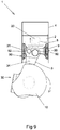
Figures 5 to 9 show a cross section of a mounted engine cylinder of the invention in different positions of its operating cycle; specifically,figure 5 shows the position wherein the crankshaft is at the highest position, but wherein the piston has not yet reached the top dead centre;figure 6 shows the position corresponding to the bottom dead centre, wherein the crankshaft is advanced, and therefore the head of the piston rod at the moment of the combustion at the top dead centre is advanced with respect to the axis of the crankshaft, andfigure 8 shows the piston passing through the bottom dead centre. Said figures do not show the valves or spark plugs in order to simplify the figures. - The combustion engine (1) (see
figures 5 to 9 ) of the invention is of the type that comprises at least one hollow cylinder (4) through which a piston (2) travels (also seefig. 2 ) in a linear reciprocating motion, coupled by means of a piston rod (3) (also seefig 1 ) to a crankshaft (10), wherein according to the invention, the piston rod (3) comprises (seefig. 1 ): - a first hub (5) arranged in its head (30) for coupling with the crankshaft (10),
- a second hub (6) arranged in its foot (31), and which is substantially aligned or parallel to the first hub (5) in the longitudinal direction (40) of the cylinder (4) when the crankshaft (10) is in the upper or lower position (see
figs. 5 and8 , respectively), and - a third hub (7) also arranged in the foot (31) of the piston rod (3), which is offset laterally towards the front with respect to the second hub (6) in the advance direction of the crankshaft (10);
- the piston (2) being coupled with the third hub (7) to reach the top dead centre (TDC) when the piston rod (3) is advanced in the direction of rotation of the crankshaft (10), as shown in
fig. 6 , wherein the height B is less than the height A, which is the height the piston (2) reaches when the crankshaft is in the upper position (seefig 5 ), and which is also reached when the piston (2) is moving downwards again, as seen infigure 7 ; - comprising a guide (9) (also see
fig 4 ) to guide the travel of the piston rod (3) through the cylinder (4) coupled with the second hub (6), and - the piston (2) being coupled with the third hub (7) via a link rod (8) (also see
fig 3 ) in order to enable a clearance between the piston (2) and the guide (9) during the reciprocating motion. - More preferably, the link rod (8) is in the shape of a fork, the side branches (80) of which are coupled to the third hub (7) of the piston rod (3), the central branch (81) of which is coupled with the piston (2) through the corresponding bolts (20), since in this manner the piston rod (8) can continue to have an essentially flat configuration and the piston (2) can have its traditional shape in order to enable the coupling thereof by means of the bolt (20), although with shorter skirts (22).
- In turn, the guide (9) ideally comprises a body with the general shape of a crown to enable the piston rod (3) to pass through the inside thereof and further surround the walls of the cylinder (4), having at least two curved faces (90) (see
fig. 4 ) making contact with the walls of the cylinder (4) (which will then be facing one another, as seen in the figures), comprising a fourth hub (91) for coupling with the second hub (6) through an additional bolt (20a). This configuration with two curved faces (90) minimises the contact surfaces with the cylinder (4) as much as possible while maintaining the guide. - To achieve a good lubrication of the curved faces (90) in contact with the walls of the cylinder (4), the invention envisages that the guide (9) preferably comprises oilers (92) to supply oil to said curved faces (90). These oilers (92) are ideally fed by means of a duct (34) that is made through the inside of the piston rod (3) through which pressurised oil runs and flows out at the second hub (6), to which said oilers (92) have access, the additional bolt (20a) in this case comprising an internal duct (23) with accesses (24) facing the duct (34) and oilers (92) to channel the oil to the same.
- For optimal operation, wherein the advance of the piston rod has the most favourable angle when the piston (2) is at the top dead centre, the third hub (7) must be arranged (see
fig. 1 ) in an area comprised in an angle from +60 degrees to -60 degrees with respect to a direction (11) that passes through the centre of the second hub (6) perpendicularly to the imaginary line (12) that joins the centre of the first hub (5) of the head (30) of the piston rod (3) and the centre of the second hub (6) of the foot (31) of the piston rod (3). The best results have been achieved when said area is comprised between +45 degrees and -45 degrees. - Lastly, it must be mentioned that, ideally, the head (30) of the piston rod (3) comprises a detachable section (33) in order to be able to detachably fasten it to the crankshaft (10).
- Having sufficiently described the nature of the invention, in addition to the manner of applying it in practice, it must hereby be stated that the aforementioned arrangements indicated and represented in the attached drawings are susceptible to modifications with regard to the detail provided that they do not alter the fundamental principle of the invention.
Claims (8)
- A combustion engine (1) of the type that comprises at least one (4) hollow cylinder, inside of which a piston (2) travels in a linear reciprocating motion, coupled by means of a piston rod (3) to a crankshaft (10), characterised in that the piston rod (3) comprises:- a first hub (5) arranged in its head (30) for coupling with the crankshaft (10),- a second hub (6) arranged in its foot (31), and which is substantially aligned with or parallel to the first hub (5) in the longitudinal direction (40) of the cylinder when the crankshaft (10) is in the upper or lower position, and- a third hub (7) also arranged in the foot (31) of the piston rod (3), which is offset laterally towards the front with respect to the second hub (6) in the direction of rotation of the crankshaft (10);- the piston (2) being coupled with the third hub (7) to reach the top dead centre TDC when the piston rod (3) is advanced in the advance direction of the crankshaft (10),- comprising a guide (9) to guide the travel of the piston rod (3) through the cylinder (4) coupled with the second hub (6), and- the piston (2) being coupled with the third hub (7) via a link rod (8) in order to enable a clearance between the piston (2) and the guide (9) during the reciprocating motion.
- The combustion engine (1) according to claim 1 characterised in that the link rod (8) is in the shape of a fork, the side branches (80) of which are coupled to the third hub (7) of the piston rod (3), the central branch (81) of which is coupled with the piston (2) through the corresponding bolts (20).
- The combustion engine (1) according to any of the preceding claims characterised in that the guide (9) comprises a body with the general shape of a crown to enable the passage of the piston rod (3), with at least two curved faces (90) making contact with the walls of the cylinder (4), comprising a fourth hub (91) for coupling with the second hub (6) through an additional bolt (20a).
- The combustion engine (1) according to any of the preceding claims characterised in that the guide (9) comprises oilers (92) to supply oil to the curved faces (90).
- The combustion engine (1) according to claim 4 characterised in that the oilers (92) are fed by means of a duct (34) that is made through the inside of the piston rod (3) through which pressurised oil runs and flows out at the second hub (6), to which said oilers (92) have access; the additional bolt (20a) comprising an internal duct (23) with accesses (24) facing the duct (34) and oilers (92) to channel the oil to the same.
- The combustion engine (1) according to any of the preceding claims characterised in that the third hub (7) is arranged in an area comprised in an angle from +60 degrees to -60 degrees with respect to a direction (11) that passes through the centre of the second hub (6) perpendicularly to the imaginary line (12) that joins the centre of the first hub (5) of the head (30) of the piston rod (3) and the centre of the second hub (6) of the foot (31) of the piston rod (3).
- The combustion engine (1) according to claim 6 characterised in that the third hub (7) is arranged in an area comprised in an angle between +45 degrees and -45 degrees with respect to a direction (11) that passes through the centre of the second hub (6) perpendicularly to the imaginary line (12) that joins the centre of the first hub (5) of the head (30) of the piston rod (3) and the centre of the second hub (6) of the foot (31) of the piston rod (3).
- The combustion engine (1) according to any of the preceding claims characterised in that the head (30) of the piston rod (3) comprises a detachable section (33) in order to be able to detachably fasten it to the crankshaft (10).
Applications Claiming Priority (2)
| Application Number | Priority Date | Filing Date | Title |
|---|---|---|---|
| ES201830114A ES2722476B2 (en) | 2018-02-09 | 2018-02-09 | EXPLOSION ENGINE |
| PCT/ES2019/070068 WO2019155108A1 (en) | 2018-02-09 | 2019-02-08 | Combustion engine |
Publications (2)
| Publication Number | Publication Date |
|---|---|
| EP3751110A1 true EP3751110A1 (en) | 2020-12-16 |
| EP3751110A4 EP3751110A4 (en) | 2021-12-01 |
Family
ID=67513761
Family Applications (1)
| Application Number | Title | Priority Date | Filing Date |
|---|---|---|---|
| EP19751880.6A Pending EP3751110A4 (en) | 2018-02-09 | 2019-02-08 | Combustion engine |
Country Status (5)
| Country | Link |
|---|---|
| US (1) | US20200400066A1 (en) |
| EP (1) | EP3751110A4 (en) |
| CN (1) | CN111699308A (en) |
| ES (1) | ES2722476B2 (en) |
| WO (1) | WO2019155108A1 (en) |
Families Citing this family (1)
| Publication number | Priority date | Publication date | Assignee | Title |
|---|---|---|---|---|
| US11885378B2 (en) * | 2021-06-04 | 2024-01-30 | Alfadan, Inc. | Cylinder unit for eliminating secondary forces in inline internal combustion engines |
Family Cites Families (13)
| Publication number | Priority date | Publication date | Assignee | Title |
|---|---|---|---|---|
| US1379115A (en) * | 1919-06-19 | 1921-05-24 | Mallory Marion | Internal-combustion engine |
| US2074581A (en) * | 1934-01-06 | 1937-03-23 | Robert G Frye | Piston for engines |
| FR833509A (en) * | 1938-02-11 | 1938-10-24 | Piston | |
| US2368412A (en) * | 1943-10-11 | 1945-01-30 | William H Cords | Internal-combustion engine |
| US3034362A (en) * | 1960-07-21 | 1962-05-15 | Alfred M Caddell | Crank actuated means for retaining fluid pressure at top center |
| DE3129630A1 (en) * | 1981-07-28 | 1983-02-17 | Wenzel 3500 Kassel Schubert | Piston drive mechanism for reciprocating piston internal combustion engine |
| DE3222568A1 (en) * | 1982-06-16 | 1983-12-22 | Josef 6761 Katzenbach Wilhelm | Piston in piston |
| US4567866A (en) * | 1984-12-26 | 1986-02-04 | Hans Schubert | Piston crankshaft interface |
| US4974554A (en) * | 1989-08-17 | 1990-12-04 | Emery Lloyd H | Compound rod, sleeve and offset crankshaft assembly |
| WO1994025745A1 (en) * | 1993-05-04 | 1994-11-10 | Allsopp, Judith, Olive | Piston and connecting rod assembly |
| US5816201A (en) * | 1997-07-07 | 1998-10-06 | Garvin; Edward A. | Offset crankshaft mechanism for an internal combustion engine |
| US8720410B2 (en) * | 2012-10-08 | 2014-05-13 | Hans G. Schubert | Modified crankshaft piston interface for optimized cylinder pressure and torque output |
| DE102015203387A1 (en) * | 2015-02-25 | 2016-08-25 | Fev Gmbh | Double-acting piston of a VCR engine |
-
2018
- 2018-02-09 ES ES201830114A patent/ES2722476B2/en active Active
-
2019
- 2019-02-08 WO PCT/ES2019/070068 patent/WO2019155108A1/en unknown
- 2019-02-08 EP EP19751880.6A patent/EP3751110A4/en active Pending
- 2019-02-08 US US16/968,410 patent/US20200400066A1/en not_active Abandoned
- 2019-02-08 CN CN201980012532.8A patent/CN111699308A/en active Pending
Also Published As
| Publication number | Publication date |
|---|---|
| ES2722476A8 (en) | 2020-08-07 |
| EP3751110A4 (en) | 2021-12-01 |
| ES2722476B2 (en) | 2021-10-07 |
| US20200400066A1 (en) | 2020-12-24 |
| CN111699308A (en) | 2020-09-22 |
| ES2722476A1 (en) | 2019-08-12 |
| WO2019155108A1 (en) | 2019-08-15 |
Similar Documents
| Publication | Publication Date | Title |
|---|---|---|
| US5927236A (en) | Variable stroke mechanism for internal combustion engine | |
| JP2004536252A (en) | Split 4-stroke cycle internal combustion engine | |
| US8967097B2 (en) | Variable stroke mechanism for internal combustion engine | |
| US5544627A (en) | Engine design for gasoline/diesel engines | |
| KR101650818B1 (en) | Variable stroke mechanism for internal combustion engine | |
| US20150300241A1 (en) | Opposed Piston Engine | |
| US10267225B2 (en) | Internal combustion engine | |
| US20160025002A1 (en) | Improved opposed piston engine | |
| US20150300242A1 (en) | Internal combustion engine with asymmetric port timing | |
| EP3751110A1 (en) | Combustion engine | |
| US10287971B2 (en) | Opposed piston engine | |
| US11519305B2 (en) | Internal combustion engine system | |
| CN103742263A (en) | Connecting rod piston type combustion chamber combined dead-center-free reciprocating internal combustion engine | |
| CN103850790B (en) | Without dead point reciprocating internal combustion engine | |
| NL2018451B1 (en) | Engine with two annular cylinders and two crankshafts | |
| CN203702338U (en) | Dead-point-free reciprocating internal combustion engine with connecting rod piston type combination combustor | |
| AU2008201574B2 (en) | "Martin" cross-flow, 4 stroke side-valve engine | |
| CN1558097A (en) | Single-crankshaft opposite vertex piston internal combustion engine with double-barrel working simultaneously | |
| US8904990B2 (en) | Dwell cycle crank with rollers | |
| RU2536640C1 (en) | Internal combustion engine | |
| CN102877943B (en) | Oscillating-shaft engine | |
| WO2022105984A1 (en) | An internal combustion engine system | |
| WO2018147819A1 (en) | Internally compressed two stroke environmentally friendly engine | |
| JPS63295821A (en) | Internal combustion engine | |
| WO2011113079A1 (en) | Martin" cross-flow, 4 stroke side- valve engine |
Legal Events
| Date | Code | Title | Description |
|---|---|---|---|
| STAA | Information on the status of an ep patent application or granted ep patent |
Free format text: STATUS: THE INTERNATIONAL PUBLICATION HAS BEEN MADE |
|
| PUAI | Public reference made under article 153(3) epc to a published international application that has entered the european phase |
Free format text: ORIGINAL CODE: 0009012 |
|
| STAA | Information on the status of an ep patent application or granted ep patent |
Free format text: STATUS: REQUEST FOR EXAMINATION WAS MADE |
|
| 17P | Request for examination filed |
Effective date: 20200810 |
|
| AK | Designated contracting states |
Kind code of ref document: A1 Designated state(s): AL AT BE BG CH CY CZ DE DK EE ES FI FR GB GR HR HU IE IS IT LI LT LU LV MC MK MT NL NO PL PT RO RS SE SI SK SM TR |
|
| AX | Request for extension of the european patent |
Extension state: BA ME |
|
| DAV | Request for validation of the european patent (deleted) | ||
| DAX | Request for extension of the european patent (deleted) | ||
| A4 | Supplementary search report drawn up and despatched |
Effective date: 20211028 |
|
| RIC1 | Information provided on ipc code assigned before grant |
Ipc: F02B 41/04 20060101ALI20211022BHEP Ipc: F02B 75/32 20060101AFI20211022BHEP |
|
| STAA | Information on the status of an ep patent application or granted ep patent |
Free format text: STATUS: EXAMINATION IS IN PROGRESS |
|
| 17Q | First examination report despatched |
Effective date: 20231110 |