EP3751078A1 - Electronic lock and method for accessing the same - Google Patents
Electronic lock and method for accessing the same Download PDFInfo
- Publication number
- EP3751078A1 EP3751078A1 EP19180072.1A EP19180072A EP3751078A1 EP 3751078 A1 EP3751078 A1 EP 3751078A1 EP 19180072 A EP19180072 A EP 19180072A EP 3751078 A1 EP3751078 A1 EP 3751078A1
- Authority
- EP
- European Patent Office
- Prior art keywords
- indication
- unit
- control module
- rotary seat
- string
- Prior art date
- Legal status (The legal status is an assumption and is not a legal conclusion. Google has not performed a legal analysis and makes no representation as to the accuracy of the status listed.)
- Granted
Links
Images






Classifications
-
- E—FIXED CONSTRUCTIONS
- E05—LOCKS; KEYS; WINDOW OR DOOR FITTINGS; SAFES
- E05B—LOCKS; ACCESSORIES THEREFOR; HANDCUFFS
- E05B47/00—Operating or controlling locks or other fastening devices by electric or magnetic means
- E05B47/06—Controlling mechanically-operated bolts by electro-magnetically-operated detents
- E05B47/0611—Cylinder locks with electromagnetic control
- E05B47/0638—Cylinder locks with electromagnetic control by disconnecting the rotor
- E05B47/0642—Cylinder locks with electromagnetic control by disconnecting the rotor axially, i.e. with an axially disengaging coupling element
-
- E—FIXED CONSTRUCTIONS
- E05—LOCKS; KEYS; WINDOW OR DOOR FITTINGS; SAFES
- E05B—LOCKS; ACCESSORIES THEREFOR; HANDCUFFS
- E05B47/00—Operating or controlling locks or other fastening devices by electric or magnetic means
- E05B47/06—Controlling mechanically-operated bolts by electro-magnetically-operated detents
- E05B47/0676—Controlling mechanically-operated bolts by electro-magnetically-operated detents by disconnecting the handle
- E05B47/068—Controlling mechanically-operated bolts by electro-magnetically-operated detents by disconnecting the handle axially, i.e. with an axially disengaging coupling element
-
- E—FIXED CONSTRUCTIONS
- E05—LOCKS; KEYS; WINDOW OR DOOR FITTINGS; SAFES
- E05B—LOCKS; ACCESSORIES THEREFOR; HANDCUFFS
- E05B49/00—Electric permutation locks; Circuits therefor ; Mechanical aspects of electronic locks; Mechanical keys therefor
-
- G—PHYSICS
- G07—CHECKING-DEVICES
- G07C—TIME OR ATTENDANCE REGISTERS; REGISTERING OR INDICATING THE WORKING OF MACHINES; GENERATING RANDOM NUMBERS; VOTING OR LOTTERY APPARATUS; ARRANGEMENTS, SYSTEMS OR APPARATUS FOR CHECKING NOT PROVIDED FOR ELSEWHERE
- G07C9/00—Individual registration on entry or exit
- G07C9/00174—Electronically operated locks; Circuits therefor; Nonmechanical keys therefor, e.g. passive or active electrical keys or other data carriers without mechanical keys
- G07C9/00658—Electronically operated locks; Circuits therefor; Nonmechanical keys therefor, e.g. passive or active electrical keys or other data carriers without mechanical keys operated by passive electrical keys
- G07C9/00666—Electronically operated locks; Circuits therefor; Nonmechanical keys therefor, e.g. passive or active electrical keys or other data carriers without mechanical keys operated by passive electrical keys with dials
-
- E—FIXED CONSTRUCTIONS
- E05—LOCKS; KEYS; WINDOW OR DOOR FITTINGS; SAFES
- E05B—LOCKS; ACCESSORIES THEREFOR; HANDCUFFS
- E05B47/00—Operating or controlling locks or other fastening devices by electric or magnetic means
- E05B2047/0094—Mechanical aspects of remotely controlled locks
- E05B2047/0095—Mechanical aspects of locks controlled by telephone signals, e.g. by mobile phones
-
- G—PHYSICS
- G07—CHECKING-DEVICES
- G07C—TIME OR ATTENDANCE REGISTERS; REGISTERING OR INDICATING THE WORKING OF MACHINES; GENERATING RANDOM NUMBERS; VOTING OR LOTTERY APPARATUS; ARRANGEMENTS, SYSTEMS OR APPARATUS FOR CHECKING NOT PROVIDED FOR ELSEWHERE
- G07C9/00—Individual registration on entry or exit
- G07C9/00174—Electronically operated locks; Circuits therefor; Nonmechanical keys therefor, e.g. passive or active electrical keys or other data carriers without mechanical keys
- G07C2009/00753—Electronically operated locks; Circuits therefor; Nonmechanical keys therefor, e.g. passive or active electrical keys or other data carriers without mechanical keys operated by active electrical keys
- G07C2009/00769—Electronically operated locks; Circuits therefor; Nonmechanical keys therefor, e.g. passive or active electrical keys or other data carriers without mechanical keys operated by active electrical keys with data transmission performed by wireless means
-
- G—PHYSICS
- G07—CHECKING-DEVICES
- G07C—TIME OR ATTENDANCE REGISTERS; REGISTERING OR INDICATING THE WORKING OF MACHINES; GENERATING RANDOM NUMBERS; VOTING OR LOTTERY APPARATUS; ARRANGEMENTS, SYSTEMS OR APPARATUS FOR CHECKING NOT PROVIDED FOR ELSEWHERE
- G07C9/00—Individual registration on entry or exit
- G07C9/00174—Electronically operated locks; Circuits therefor; Nonmechanical keys therefor, e.g. passive or active electrical keys or other data carriers without mechanical keys
- G07C9/00658—Electronically operated locks; Circuits therefor; Nonmechanical keys therefor, e.g. passive or active electrical keys or other data carriers without mechanical keys operated by passive electrical keys
- G07C9/00674—Electronically operated locks; Circuits therefor; Nonmechanical keys therefor, e.g. passive or active electrical keys or other data carriers without mechanical keys operated by passive electrical keys with switch-buttons
- G07C9/0069—Electronically operated locks; Circuits therefor; Nonmechanical keys therefor, e.g. passive or active electrical keys or other data carriers without mechanical keys operated by passive electrical keys with switch-buttons actuated in a predetermined sequence
Definitions
- the disclosure relates to an electronic lock, and more particularly to an electronic lock and a method for accessing the electronic lock.
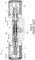
- a conventional electronic lock 1 disclosed in Chinese Patent Publication No. 103670037B includes an inner handle seat 11, an outer handle seat 12, a lock core unit 13, two latching units 14, a sensing unit 15 and a driving unit 16.
- the lock core unit 13 is disposed between the inner handle seat 11 and the outer handle seat 12, and includes a core axle 131 that extends in a core direction (D), a core tube 132 that surrounds the core axle 131, and a locking block 133 that is co-movably mounted to the core tube 132 and that is for engaging a locking groove (not shown).
- the core tube 132 has two latch grooves 134 at two opposite ends thereof that are respectively proximate to the inner handle seat 11 and the outer handle seat 12.
- the latching units 14 are respectively mounted to the inner handle seat 11 and the outer handle seat 12.
- Each of the latching units 14 includes a latch member 141 that rotates along with the corresponding inner and outer handle seats 11, 12 and that is movable relative to the corresponding inner and outer handle seats 11, 12 in the core direction (D) .
- the latch members 141 of the latching units 14 are respectively and co-movably mounted to two opposite ends of the core axle 131.
- the sensing unit 15 includes an inner sensor 151 that is mounted in the inner handle seat 11, and an outer sensor 152 that is mounted in the outer handle seat 12.
- the driving unit 16 includes a driving motor 160 that is disposed in the inner handle seat 11, and a resilient member 162 that has two opposite ends respectively connected to an output shaft 161 of the driving motor 160 and one of the latch members 141 of the latching units 14.
- a sensing card (not shown) approaches one of the inner and outer handle seats 11, 12, the driving motor 160 drives the corresponding one of the latch members 141 of the latching units 14 to engage the corresponding latch groove 134 of the core tube 132, such that the locking block 133 is operable by turning the one of the inner and outer handle seats 11, 12.
- the outer handle seat 12 is provided with a mechanical locking module 17.
- the mechanical locking module 17 is operable by a key (not shown) to move the corresponding latch member 141 to engage the corresponding latch groove 134 of the core tube 132, so as to permit the locking block 133 to be operated by turning the outer handle seat 12.
- the conventional electronic lock 1 is not accessible when both of the sensing card and the key are not available.
- an object of the disclosure is to provide an electronic lock that can alleviate the drawback of the prior art.
- the electronic lock includes a lock core unit, a driving unit, a rotary seat, an indication unit, a control module and position-sensing unit.
- the lock core unit is mounted to the door leaf along an axial line, and includes a locking block that is rotatable about the axial line.
- the driving unit includes a latch member that is operable to removably engage the locking block, and an actuator that is operable to drive the latch member to move along the axial line.
- the latch member is movable along the axial line relative to the locking block between an engaging position and a disengaging position. The latch member engages the locking block when the latch member is at the engaging position.
- the latch member is disengaged from the locking block when the latch member is at the disengaging position.
- the rotary seat is rotatable about the axial line, and is disposed on the door leaf for being gripped by a user.
- the actuator is mounted to the rotary seat, and is rotatable along with the rotary seat.
- the rotary seat is able to drive rotation of the locking block via the driving unit when the latch member is at the engaging position.
- the rotary seat is unable to drive rotation of the locking block when the latch member is at the disengaging position.
- the indication unit is disposed on the rotary seat, and includes a plurality of indication regions that are disposed about the axial line and that are disposed on an outer surface of the rotary seat.
- the indication regions are in the form of characters, and respectively correspond to different angular positions of the rotary seat.
- the control module is mounted to the rotary seat, and is electrically coupled to the driving unit for controlling the actuator of the driving unit.
- the position-sensing unit is disposed on the rotary seat for sensing the angular position of the rotary seat, and is electrically coupled to the control module to output a position signal to the control module upon sensing the angular position of the rotary seat.
- the control module is configured to receive the output from the position-sensing unit to thereby compose a string, and then compares the composed string with a built-in string. When the composed string matches the built-in string, the control module sends an engaging command to the driving unit for moving the latch member to the engaging position.
- Another object of the disclosure is to provide a method for accessing an electronic lock that can alleviate the drawback of the prior art.
- the method is for accessing the abovementioned electronic lock, and includes steps of: a) repeatedly turning the rotary seat to repeatedly output, by the position-sensing unit, characters to the control module; b) stopping the control module from receiving the outputs from the position-sensing unit after a predetermined amount of the outputs from the position-sensing unit has been received, and determining, by the control module, the composed string of characters by sequentially arranging the received outputs from the position-sensing unit; and c) comparing, by the control module, the composed string of characters with the built-in string of characters.
- the control module commands the indication unit to generate a success indication, and sends the engaging command to the driving unit to move the latch member to the engaging position.
- the control module commands the indication unit to generate a failure indication.
- an embodiment of the electronic lock according to the disclosure is adapted to be mounted to a door leaf 100, and is accessible by a sensing card 200.
- the sensing card 200 has a sensing tag 201 that stores identification data therein.
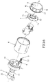
- the electronic lock includes a lock core unit 2, a driving unit 3, a rotary seat 4, a control module 5, a position-sensing unit 6, an indication unit 7 and an awaking unit 8.
- the lock core unit 2 is mounted to the door leaf 100 along an axial line (L), and includes a core tube 21 that extends along the axial line (L), and a locking block 22 that is located at one side of the core tube 21 and that is rotatable about the axial line (L).
- the locking block 22 has two engaging grooves 221 (see Figure 5 ) that are formed in an inner surrounding surface of the locking block 22 and that are diametrically opposite to each other.
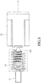
- the driving unit 3 is disposed in the core tube 21, and includes a latch member 31 that is operable to removably engage the engaging grooves 221 of the locking block 22, an actuator 32 (see Figure 7 ) that is operable to drive the latch member 31 to move along the axial line (L), and a resilient member 33 (see Figure 8 ).
- the actuator 32 has an output shaft 321 that extends toward the latch member 31 and that is rotatable about the axial line (L).
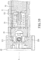
- the resilient member 33 is disposed between the latch member 31 and the actuator 32, and has two opposite ends respectively connected to the latch member 31 and the output shaft 321 of the actuator 32, such that rotation of the output shaft 321 drives the latch member 31 to move along the axial line (L) relative to the locking block 22 between an engaging position (see Figure 9 ) and a disengaging position (see Figure 10 ).
- the resilient member 33 is stretched, and the latch member 31 engages the engaging grooves 221 of the locking block 22 such that the locking block 22 is co-rotatable with the latch member 31.
- the output shaft 321 of the actuator 32 is configured as a worm shaft.
- the rotary seat 4 surrounds the axial line (L), and is rotatable about the axial line (L) .
- the rotary seat 4 is connected to the core tube 21, and is disposed on the door leaf 100 (see Figure 3 ) for being gripped by a user.
- rotation of the rotary seat 4 drives the locking block 22 to rotate for disengaging the locking block 22 from a locking groove (not shown) formed in a door frame.
- the rotary seat 4 is configured not to drive movement of the locking block 22, so that the door leaf 100 cannot be opened.
- the actuator 32 is co-rotatably mounted to the rotary seat 4.
- the control module 5 is disposed in the rotary seat 4, and is configured to send an engaging command to the driving unit 3 for moving the latch member 31 to the engaging position.
- the electronic lock is further able to communicate with a mobile device 300, such as a smartphone.
- the mobile device 300 is configured to emit an engaging signal to the control module 5, and the control module 5 sends the engaging command to the driving unit 3 upon receiving the engaging signal.
- the control module 5 includes a reading unit 51 for sensing the identification data in the sensing card 200, a processing unit 52, and a communication unit 53 for communicating with the mobile device 300.
- the processing unit 52 is electrically coupled to the reading unit 51, the communication unit 53 and the driving unit 3, and sends the engaging command to the driving unit 3 upon detecting the identification data in the sensing card 200 via the reading unit 51, or upon receiving the engaging signal from the mobile device 300 via the communication unit 53.
- the reading unit 51 communicates with the sensing card 200 by virtue of Radio Frequency Identification (RFID) technology
- the sensing tag 201 is configured as an RFID tag
- the reading unit 51 is configured as an RFID reader.
- the communication unit 53 communicates with the mobile device 300 by virtue of Bluetooth technology. Other wireless communication technologies may be employed in a modification.
- the position-sensing unit 6 is disposed on the rotary seat 4, and is electrically coupled to the processing unit 52 for detecting the angular position of the rotary seat 4.
- the position-sensing unit 6 may be configured as an inertial measurement unit (IMU) that includes accelerometers (G-sensors) and gyroscopes.
- IMU inertial measurement unit
- the indication unit 7 is disposed on the rotary seat 4, and is electrically coupled to the processing unit 52.
- the indication unit 7 includes a plurality of indication regions 41, a plurality of LED (light-emitting diode) lamps 71 and a buzzer 72.
- the indication regions 41 are disposed about the axial line (L), and are disposed on an outer surface of the rotary seat 4.
- each of the indication regions 41 is configured as a hollow structure that is formed in the rotary seat 4.
- each of the indication regions 41 may be made of a light-transmissible material, and is mounted to the rotary seat 4.
- the indication unit 7 may further include a determination indication region 42 that is disposed between two of the indication regions 41.
- the determination indication region 42 is configured as a hollow structure in this embodiment, but may be made of a light-transmissible material in a modification. It should be noted that, in this embodiment, the indication regions 41 are in the form of Arabic numerals, but may be in the form of other characters in a modification. Similarly, the determination indication region 42 is in the form of the symbol "#" in this embodiment, but may be in the form of another character in a modification.
- the indication regions 41 and the determination indication region 42 respectively correspond to different angular positions of the rotary seat 4.
- the position-sensing unit 6 is configured to sense the angular position of the rotary seat 4, and then to output the character that is presented in the corresponding indication region 41 or determination indication region 42 to the processing unit 52 of the control module 5.
- the position-sensing unit 6 may indirectly output characters to the processing unit 52.
- the position-sensing unit 6 may output a position signal to the processing unit 52 upon sensing the angular position of the rotary seat 4, and the processing unit 52 determines a corresponding character upon the received position signal from the position-sensing unit 6.
- the LED lamps 71 are disposed on the rotary seat 4, and respectively correspond in position to the indication regions 41 and the determination indication region 42 for respectively illuminating the indication regions 41 and the determination indication region 42.
- the indication unit 7 is operable to generate a position indication, a success indication and a failure indication.
- the processing unit 52 of the control module 5 receives the output signal from the position-sensing unit 6, the processing unit 52 commands the indication unit 7 to generate the position indication.
- the position indication is to intermittently illuminate the corresponding indication region 41 or determination indication region 42 upon the angular position of the rotary seat 4 detected by the position-sensing unit 6.
- the processing unit 52 of the control module 5 is configured to receive a sequence of outputs from the position-sensing unit 6, and to compose a string of characters by sequentially arranging the outputs from the position-sensing unit 6. The processing unit 52 then compares the composed string of characters with a built-in string of characters. When the composed string matches the built-in string, the processing unit 52 commands the indication unit 7 to generate the success indication. In this embodiment, the success indication is to intermittently illuminate all of the indication regions 41 and the determination indication region 42, and to send the engaging command to the driving unit 3 so as to move the latch member 31 to the engaging position. When the composed string does not match the built-in string, the processing unit 52 commands the indication unit 7 to generate the failure indication. In this embodiment, the failure indication is to command the buzzer 72 to generate a sound. In a modification, various indications may be generated by combining different illumination modes of the LED lamps 71 and different sounds generated by the buzzer 72.
- the processing unit 52 may receive a predetermined amount of the outputs from the position-sensing unit 6 to determine the composed string of characters. In a modification, the processing unit 52 keeps receiving the outputs from the position-sensing unit 6 until the character corresponding to the determination indication region 42 is received, and then determines the composed string of characters upon the received outputs from the position-sensing unit 6. The processing unit 52 may determine the composed string of characters by other approaches.
- the awaking unit 8 is disposed on the rotary seat 4, and is electrically coupled to the processing unit 52.
- the awaking unit 8 emits an awaking signal to the processing unit 52 upon being depressed, and the processing unit 52 then switches the position-sensing unit 6 from an idle state to an active state.
- the position-sensing unit 6 cannot detect the angular position of the rotary seat 4 when being in the idle state.
- the position-sensing unit 6 is able to detect the angular position of the rotary seat 4 when being switched into the active state, so as to permit determination of the composed string of characters for disengaging the locking block 22 from the locking groove (not shown) (i.e., for opening the door leaf 100) .
- the reading unit 51 of the control module 5 may be omitted.
- a method for accessing the electronic lock according to the disclosure includes steps of:
- the position-sensing unit 6 may be configured to output a character to the processing unit 52 after the rotary seat 4 has stayed at the corresponding angular position for a predetermined period of time, so as to prevent unwanted outputs therefrom.
- the predetermined period of time may be a second, 0.5 seconds, or other time intervals.
- step 93 the composed string of characters determined by the processing unit 52 may not include the character corresponding to the determination indication region 42.
- the electronic lock according to the disclosure is accessible via the sensing card 200 or the mobile device 300, or by repeatedly turning the rotary seat 4, the electronic lock can be operated to open the door leaf 100 when both of the sensing card 200 and the mobile device 300 are not available.
Landscapes
- Physics & Mathematics (AREA)
- General Physics & Mathematics (AREA)
- Electromagnetism (AREA)
- Lock And Its Accessories (AREA)
Abstract
Description
- The disclosure relates to an electronic lock, and more particularly to an electronic lock and a method for accessing the electronic lock.
- Referring to
Figures 1 and2 , a conventionalelectronic lock 1 disclosed in Chinese Patent Publication No.103670037B includes aninner handle seat 11, anouter handle seat 12, alock core unit 13, twolatching units 14, asensing unit 15 and adriving unit 16. Thelock core unit 13 is disposed between theinner handle seat 11 and theouter handle seat 12, and includes acore axle 131 that extends in a core direction (D), acore tube 132 that surrounds thecore axle 131, and alocking block 133 that is co-movably mounted to thecore tube 132 and that is for engaging a locking groove (not shown). Thecore tube 132 has twolatch grooves 134 at two opposite ends thereof that are respectively proximate to theinner handle seat 11 and theouter handle seat 12. Thelatching units 14 are respectively mounted to theinner handle seat 11 and theouter handle seat 12. Each of thelatching units 14 includes alatch member 141 that rotates along with the corresponding inner andouter handle seats outer handle seats latch members 141 of thelatching units 14 are respectively and co-movably mounted to two opposite ends of thecore axle 131. Thesensing unit 15 includes aninner sensor 151 that is mounted in theinner handle seat 11, and anouter sensor 152 that is mounted in theouter handle seat 12. Thedriving unit 16 includes adriving motor 160 that is disposed in theinner handle seat 11, and aresilient member 162 that has two opposite ends respectively connected to anoutput shaft 161 of thedriving motor 160 and one of thelatch members 141 of thelatching units 14. When a sensing card (not shown) approaches one of the inner andouter handle seats driving motor 160 drives the corresponding one of thelatch members 141 of thelatching units 14 to engage thecorresponding latch groove 134 of thecore tube 132, such that thelocking block 133 is operable by turning the one of the inner andouter handle seats outer handle seat 12 is provided with amechanical locking module 17. Themechanical locking module 17 is operable by a key (not shown) to move thecorresponding latch member 141 to engage thecorresponding latch groove 134 of thecore tube 132, so as to permit thelocking block 133 to be operated by turning theouter handle seat 12. - However, the conventional
electronic lock 1 is not accessible when both of the sensing card and the key are not available. - Therefore, an object of the disclosure is to provide an electronic lock that can alleviate the drawback of the prior art.
- According to the disclosure, the electronic lock includes a lock core unit, a driving unit, a rotary seat, an indication unit, a control module and position-sensing unit. The lock core unit is mounted to the door leaf along an axial line, and includes a locking block that is rotatable about the axial line. The driving unit includes a latch member that is operable to removably engage the locking block, and an actuator that is operable to drive the latch member to move along the axial line. The latch member is movable along the axial line relative to the locking block between an engaging position and a disengaging position. The latch member engages the locking block when the latch member is at the engaging position. The latch member is disengaged from the locking block when the latch member is at the disengaging position. The rotary seat is rotatable about the axial line, and is disposed on the door leaf for being gripped by a user. The actuator is mounted to the rotary seat, and is rotatable along with the rotary seat. The rotary seat is able to drive rotation of the locking block via the driving unit when the latch member is at the engaging position. The rotary seat is unable to drive rotation of the locking block when the latch member is at the disengaging position. The indication unit is disposed on the rotary seat, and includes a plurality of indication regions that are disposed about the axial line and that are disposed on an outer surface of the rotary seat. The indication regions are in the form of characters, and respectively correspond to different angular positions of the rotary seat. The control module is mounted to the rotary seat, and is electrically coupled to the driving unit for controlling the actuator of the driving unit. The position-sensing unit is disposed on the rotary seat for sensing the angular position of the rotary seat, and is electrically coupled to the control module to output a position signal to the control module upon sensing the angular position of the rotary seat. The control module is configured to receive the output from the position-sensing unit to thereby compose a string, and then compares the composed string with a built-in string. When the composed string matches the built-in string, the control module sends an engaging command to the driving unit for moving the latch member to the engaging position.
- Another object of the disclosure is to provide a method for accessing an electronic lock that can alleviate the drawback of the prior art.
- According to the disclosure, the method is for accessing the abovementioned electronic lock, and includes steps of: a) repeatedly turning the rotary seat to repeatedly output, by the position-sensing unit, characters to the control module; b) stopping the control module from receiving the outputs from the position-sensing unit after a predetermined amount of the outputs from the position-sensing unit has been received, and determining, by the control module, the composed string of characters by sequentially arranging the received outputs from the position-sensing unit; and c) comparing, by the control module, the composed string of characters with the built-in string of characters. When it is determined that the composed string matches the built-in string, the control module commands the indication unit to generate a success indication, and sends the engaging command to the driving unit to move the latch member to the engaging position. When it is determined that the composed string does not match the built-in string, the control module commands the indication unit to generate a failure indication.
- Other features and advantages of the disclosure will become apparent in the following detailed description of the embodiment with reference to the accompanying drawings, of which:
-
Figure 1 is an exploded perspective view illustrating a conventional electronic lock disclosed in Chinese Patent Publication No.103670037B ; -
Figure 2 is a sectional view illustrating the conventional electronic lock; -
Figure 3 is a perspective view illustrating an embodiment of the electronic lock according to the disclosure being mounted to a door leaf, and being accessed using a sensing card; -
Figure 4 is a perspective view illustrating the embodiment; -
Figure 5 is a partly exploded perspective view illustrating the embodiment; -
Figure 6 is another partly exploded perspective view illustrating the embodiment; -
Figure 7 is still another partly exploded perspective view illustrating the embodiment; -
Figure 8 is side view illustrating a driving unit of the embodiment; -
Figure 9 is a fragmentary sectional view illustrating a latch member of the driving unit at an engaging position; -
Figure 10 is another fragmentary sectional view illustrating the latch member at a disengaging position; -
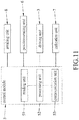
Figure 11 is a block diagram of the embodiment; -
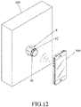
Figure 12 is a perspective view illustrating the embodiment being accessed using a mobile device; -
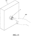
Figure 13 is a perspective view illustrating the embodiment being switch into an active state; -
Figure 14 is a perspective view illustrating the embodiment being accessed by turning a rotary seat thereof; and -
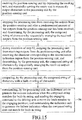
Figure 15 is a flowchart illustrating steps of a method for accessing the electronic lock according to the disclosure. - Before the disclosure is described in greater detail, it should be noted that where considered appropriate, reference numerals or terminal portions of reference numerals have been repeated among the figures to indicate corresponding or analogous elements, which may optionally have similar characteristics.
- Referring to
Figures 3 to 6 , an embodiment of the electronic lock according to the disclosure is adapted to be mounted to adoor leaf 100, and is accessible by asensing card 200. Thesensing card 200 has asensing tag 201 that stores identification data therein. - The electronic lock includes a
lock core unit 2, adriving unit 3, arotary seat 4, acontrol module 5, a position-sensing unit 6, anindication unit 7 and anawaking unit 8. - The
lock core unit 2 is mounted to thedoor leaf 100 along an axial line (L), and includes acore tube 21 that extends along the axial line (L), and alocking block 22 that is located at one side of thecore tube 21 and that is rotatable about the axial line (L). Thelocking block 22 has two engaging grooves 221 (seeFigure 5 ) that are formed in an inner surrounding surface of thelocking block 22 and that are diametrically opposite to each other. - Referring to
Figures 5 and7 to 10 , thedriving unit 3 is disposed in thecore tube 21, and includes alatch member 31 that is operable to removably engage theengaging grooves 221 of thelocking block 22, an actuator 32 (seeFigure 7 ) that is operable to drive thelatch member 31 to move along the axial line (L), and a resilient member 33 (seeFigure 8 ). Theactuator 32 has anoutput shaft 321 that extends toward thelatch member 31 and that is rotatable about the axial line (L). Theresilient member 33 is disposed between thelatch member 31 and theactuator 32, and has two opposite ends respectively connected to thelatch member 31 and theoutput shaft 321 of theactuator 32, such that rotation of theoutput shaft 321 drives thelatch member 31 to move along the axial line (L) relative to thelocking block 22 between an engaging position (seeFigure 9 ) and a disengaging position (seeFigure 10 ). When thelatch member 31 is at the engaging position, theresilient member 33 is stretched, and thelatch member 31 engages theengaging grooves 221 of thelocking block 22 such that thelocking block 22 is co-rotatable with thelatch member 31. When thelatch member 31 is at the disengaging position, theresilient member 33 is contracted, and thelatch member 31 is separated from theengaging grooves 221 of thelocking block 22 such that thelocking block 22 is not driven by rotation of thelatch member 31. In one embodiment, theoutput shaft 321 of theactuator 32 is configured as a worm shaft. - The
rotary seat 4 surrounds the axial line (L), and is rotatable about the axial line (L) . Therotary seat 4 is connected to thecore tube 21, and is disposed on the door leaf 100 (seeFigure 3 ) for being gripped by a user. When thelatch member 31 is at the engaging position, rotation of therotary seat 4 drives thelocking block 22 to rotate for disengaging thelocking block 22 from a locking groove (not shown) formed in a door frame. When thelatch member 31 is at the disengaging position, therotary seat 4 is configured not to drive movement of the lockingblock 22, so that thedoor leaf 100 cannot be opened. In one embodiment, theactuator 32 is co-rotatably mounted to therotary seat 4. - Referring to
Figures 5 ,6 ,11 and12 , thecontrol module 5 is disposed in therotary seat 4, and is configured to send an engaging command to thedriving unit 3 for moving thelatch member 31 to the engaging position. In one embodiment, the electronic lock is further able to communicate with amobile device 300, such as a smartphone. Themobile device 300 is configured to emit an engaging signal to thecontrol module 5, and thecontrol module 5 sends the engaging command to thedriving unit 3 upon receiving the engaging signal. In detail, Thecontrol module 5 includes areading unit 51 for sensing the identification data in thesensing card 200, aprocessing unit 52, and acommunication unit 53 for communicating with themobile device 300. Theprocessing unit 52 is electrically coupled to thereading unit 51, thecommunication unit 53 and thedriving unit 3, and sends the engaging command to thedriving unit 3 upon detecting the identification data in thesensing card 200 via thereading unit 51, or upon receiving the engaging signal from themobile device 300 via thecommunication unit 53. - In this embodiment, the
reading unit 51 communicates with thesensing card 200 by virtue of Radio Frequency Identification (RFID) technology, thesensing tag 201 is configured as an RFID tag, and thereading unit 51 is configured as an RFID reader. Thecommunication unit 53 communicates with themobile device 300 by virtue of Bluetooth technology. Other wireless communication technologies may be employed in a modification. - The position-sensing
unit 6 is disposed on therotary seat 4, and is electrically coupled to theprocessing unit 52 for detecting the angular position of therotary seat 4. In one embodiment, the position-sensingunit 6 may be configured as an inertial measurement unit (IMU) that includes accelerometers (G-sensors) and gyroscopes. - Referring to
Figures 6 ,11 ,13 and14 , theindication unit 7 is disposed on therotary seat 4, and is electrically coupled to theprocessing unit 52. Theindication unit 7 includes a plurality ofindication regions 41, a plurality of LED (light-emitting diode)lamps 71 and abuzzer 72. Theindication regions 41 are disposed about the axial line (L), and are disposed on an outer surface of therotary seat 4. In this embodiment, each of theindication regions 41 is configured as a hollow structure that is formed in therotary seat 4. In a modification, each of theindication regions 41 may be made of a light-transmissible material, and is mounted to therotary seat 4. Theindication unit 7 may further include adetermination indication region 42 that is disposed between two of theindication regions 41. Thedetermination indication region 42 is configured as a hollow structure in this embodiment, but may be made of a light-transmissible material in a modification. It should be noted that, in this embodiment, theindication regions 41 are in the form of Arabic numerals, but may be in the form of other characters in a modification. Similarly, thedetermination indication region 42 is in the form of the symbol "#" in this embodiment, but may be in the form of another character in a modification. Theindication regions 41 and thedetermination indication region 42 respectively correspond to different angular positions of therotary seat 4. The position-sensingunit 6 is configured to sense the angular position of therotary seat 4, and then to output the character that is presented in thecorresponding indication region 41 ordetermination indication region 42 to theprocessing unit 52 of thecontrol module 5. In one embodiment, the position-sensingunit 6 may indirectly output characters to theprocessing unit 52. For example, the position-sensingunit 6 may output a position signal to theprocessing unit 52 upon sensing the angular position of therotary seat 4, and theprocessing unit 52 determines a corresponding character upon the received position signal from the position-sensingunit 6. - The
LED lamps 71 are disposed on therotary seat 4, and respectively correspond in position to theindication regions 41 and thedetermination indication region 42 for respectively illuminating theindication regions 41 and thedetermination indication region 42. - The
indication unit 7 is operable to generate a position indication, a success indication and a failure indication. When theprocessing unit 52 of thecontrol module 5 receives the output signal from the position-sensingunit 6, theprocessing unit 52 commands theindication unit 7 to generate the position indication. In this embodiment, the position indication is to intermittently illuminate thecorresponding indication region 41 ordetermination indication region 42 upon the angular position of therotary seat 4 detected by the position-sensingunit 6. - The
processing unit 52 of thecontrol module 5 is configured to receive a sequence of outputs from the position-sensingunit 6, and to compose a string of characters by sequentially arranging the outputs from the position-sensingunit 6. Theprocessing unit 52 then compares the composed string of characters with a built-in string of characters. When the composed string matches the built-in string, theprocessing unit 52 commands theindication unit 7 to generate the success indication. In this embodiment, the success indication is to intermittently illuminate all of theindication regions 41 and thedetermination indication region 42, and to send the engaging command to thedriving unit 3 so as to move thelatch member 31 to the engaging position. When the composed string does not match the built-in string, theprocessing unit 52 commands theindication unit 7 to generate the failure indication. In this embodiment, the failure indication is to command thebuzzer 72 to generate a sound. In a modification, various indications may be generated by combining different illumination modes of theLED lamps 71 and different sounds generated by thebuzzer 72. - In one embodiment, the
processing unit 52 may receive a predetermined amount of the outputs from the position-sensingunit 6 to determine the composed string of characters. In a modification, theprocessing unit 52 keeps receiving the outputs from the position-sensingunit 6 until the character corresponding to thedetermination indication region 42 is received, and then determines the composed string of characters upon the received outputs from the position-sensingunit 6. Theprocessing unit 52 may determine the composed string of characters by other approaches. - The awaking
unit 8 is disposed on therotary seat 4, and is electrically coupled to theprocessing unit 52. The awakingunit 8 emits an awaking signal to theprocessing unit 52 upon being depressed, and theprocessing unit 52 then switches the position-sensingunit 6 from an idle state to an active state. The position-sensingunit 6 cannot detect the angular position of therotary seat 4 when being in the idle state. The position-sensingunit 6 is able to detect the angular position of therotary seat 4 when being switched into the active state, so as to permit determination of the composed string of characters for disengaging the lockingblock 22 from the locking groove (not shown) (i.e., for opening the door leaf 100) . - Since the electronic lock is accessible by virtue of the position-sensing
unit 6, in one embodiment, thereading unit 51 of thecontrol module 5 may be omitted. - Referring to
Figures 6 ,11 and15 , a method for accessing the electronic lock according to the disclosure includes steps of: - Step 91: enabling the position-sensing
unit 6 by depressing the awakingunit 8, and repeatedly turning therotary seat 4 to repeatedly output characters to theprocessing unit 52 by the position-sensingunit 6; - Step 92: stopping the
processing unit 52 from receiving the outputs from the position-sensingunit 6 after a predetermined amount of the outputs from the position-sensingunit 6 has been received, and determining, by theprocessing unit 52, the composed string of characters by sequentially arranging the received outputs from the position-sensingunit 6; - Step 93: during execution of
step 92, stopping theprocessing unit 52 from receiving outputs from the position-sensingunit 6 after receiving the character corresponding to thedetermination indication region 42 from the position-sensingunit 6, and determining, by theprocessing unit 52, the composed string of characters by sequentially arranging the received outputs from the position-sensingunit 6; - Step 94: comparing, by the
processing unit 52, the composed string of characters with a built-in string of characters; and - Step 95 : commanding, by the
processing unit 52, theindication unit 7 to generate the success indication when the composed string matches the built-in string, and sending the engaging command to thedriving unit 3 to move thelatch member 31 to the engaging position; and commanding theindication unit 7 to generate the failure indication when the composed string does not match the built-in string. - In
step 91, the position-sensingunit 6 may be configured to output a character to theprocessing unit 52 after therotary seat 4 has stayed at the corresponding angular position for a predetermined period of time, so as to prevent unwanted outputs therefrom. The predetermined period of time may be a second, 0.5 seconds, or other time intervals. - In
step 93, the composed string of characters determined by theprocessing unit 52 may not include the character corresponding to thedetermination indication region 42. - In summary, since the electronic lock according to the disclosure is accessible via the
sensing card 200 or themobile device 300, or by repeatedly turning therotary seat 4, the electronic lock can be operated to open thedoor leaf 100 when both of thesensing card 200 and themobile device 300 are not available. - In the description above, for the purposes of explanation, numerous specific details have been set forth in order to provide a thorough understanding of the embodiment. It will be apparent, however, to one skilled in the art, that one or more other embodiments may be practiced without some of these specific details. It should also be appreciated that reference throughout this specification to "one embodiment," "an embodiment," an embodiment with an indication of an ordinal number and so forth means that a particular feature, structure, or characteristic may be included in the practice of the disclosure. It should be further appreciated that in the description, various features are sometimes grouped together in a single embodiment, figure, or description thereof for the purpose of streamlining the disclosure and aiding in the understanding of various inventive aspects, and that one or more features or specific details from one embodiment may be practiced together with one or more features or specific details from another embodiment, where appropriate, in the practice of the disclosure.
Claims (10)
- An electronic lock adapted to be mounted to a door leaf (100), characterized by:a lock core unit (2) mounted to the door leaf (100) along an axial line (L), and including a locking block (22) that is rotatable about the axial line (L);a driving unit (3) including a latch member (31) that is operable to removably engage said locking block (22), and an actuator (32) that is operable to drive said latch member (31) to move along the axial line (L), said latch member (31) being movable along the axial line (L) relative to said locking block (22) between an engaging position and a disengaging position, said latch member (31) engaging said locking block (22) when said latch member (31) is at the engaging position, said latch member (31) being disengaged from said locking block (22) when said latch member (31) is at the disengaging position;a rotary seat (4) rotatable about the axial line (L), and disposed on the door leaf (100) for being gripped by a user, said actuator (32) being mounted to said rotary seat (4), and rotatable along with said rotary seat (4), said rotary seat (4) being able to drive rotation of said locking block (22) via said driving unit (3) when said latch member (31) is at the engaging position, said rotary seat (4) being unable to drive rotation of said locking block (22) when said latch member (31) is at the disengaging position;an indication unit (7) disposed on said rotary seat (4), and including a plurality of indication regions (41) that are disposed about the axial line (L) and that are disposed on an outer surface of said rotary seat (4), said indication regions (41) being in the form of characters, and respectively corresponding to different angular positions of said rotary seat (4);a control module (5) mounted to said rotary seat (4), and electrically coupled to said driving unit (3) for controlling said actuator (32) of said driving unit (3); anda position-sensing unit (6) disposed on said rotary seat (4) for sensing the angular position of said rotary seat (4), and is electrically coupled to said control module (5) to output a position signal to said control module (5) upon sensing the angular position of said rotary seat (4);wherein, said control module (5) is configured to receive the output from said position-sensing unit (6) to thereby compose a string, and then compares the composed string with a built-in string, when the composed string matches the built-in string, said control module (5) sending an engaging command to said driving unit (3) for moving said latch member (31) to the engaging position.
- The electronic lock as claimed in claim 1, characterized in that said indication unit (7) is electrically coupled to said control module (5), and is operable to generate a success indication and a failure indication, said control module (5) commanding said indication unit (7) to generate the success indication when the composed string matches the built-in string, said control module (5) commanding said indication unit (7) to generate the failure indication when the composed string does not match the built-in string.
- The electronic lock as claimed in claim 2, further characterized in that said indication unit (7) further includes plurality of light-emitting diode (LED) lamps (71) for respectively illuminating said indication regions (41), said control module (5) commanding said indication unit (7) to generate the position indication when said control module (5) receives the output signal from said position-sensing unit (6), the position indication being performed by intermittently illuminating the corresponding indication region (41) upon the angular position of said rotary seat (4) detected by said position-sensing unit (6), the success indication being performed by intermittently illuminating all of said indication regions (41).
- The electronic lock as claimed in claim 1, further characterized by an awaking unit (8) that is disposed on said rotary seat (4), and that is electrically coupled to said control module (5), said awaking unit (8) emitting an awaking signal to said control module (5) upon being depressed, and said control module (5) then switching said position-sensing unit (6) from an idle state to an active state, said position-sensing unit (6) being unable to detect the angular position of said rotary seat (4) when being in the idle state, said position-sensing unit (6) being able to detect the angular position of said rotary seat (4) when being switched into the active state.
- The electronic lock as claimed in claim 1, characterized in that said indication unit (7) further includes a determination indication region (42) that is disposed on said outer surface of said rotary seat (4), that is in the form of a character, and that corresponds to an angular position of said rotary seat (4), said control module (5) stopping receiving outputs from said position-sensing unit (6) after receiving the character corresponding to said determination indication region (42) from said position-sensing unit (6), and determining the composed string by sequentially arranging the received outputs from said position-sensing unit (6).
- The electronic lock as claimed in claim 1 adapted to communicate with a mobile device (300) that is operable to emit an engaging signal, characterized in that, said control module (5) communicates with the mobile device (300), and sends the engaging command to said driving unit (3) upon receiving the engaging signal from the mobile device (300).
- The electronic lock as claimed in claim 1, characterized in that said actuator(32) has a worm shaft (321) that extends toward said latch member (31) and that is rotatable about the axial line (L), said driving unit (3) further including a resilient member (33) that is configured to be stretched or contracted by rotation of the worm shaft (321), so as to move said latch member (31) relative to said locking block (22) .
- A method for accessing the electronic lock of claim 1, characterized by steps of:a) repeatedly turning the rotary seat (4) to repeatedly output, by the position-sensing unit (6), characters to the control module (5);b) stopping the control module (5) from receiving the outputs from the position-sensing unit (6) after a predetermined amount of the outputs from the position-sensing unit (6) has been received, and determining, by the control module (5), the composed string of characters by sequentially arranging the received outputs from the position-sensing unit (6); andc) comparing, by the control module (5), the composed string of characters with the built-in string of characters;wherein, when it is determined that the composed string matches the built-in string, the control module (5) commands the indication unit (7) to generate a success indication, and sends the engaging command to the driving unit (3) to move the latch member (31) to the engaging position; and
wherein, when it is determined that the composed string does not match the built-in string, the control module (5) commands the indication unit (7) to generate a failure indication. - The method as claimed in claim 8, further characterized by, before step a), a step of:
d) enabling the position-sensing unit (6) by depressing the awaking unit (8). - The method as claimed in claim 8, the indication unit (7) of the electronic lock further including a determination indication region (42) that is disposed on the outer surface of the rotary seat (4), that is in the form of a character, and that corresponds to an angular position of the rotary seat (4), the method being characterized in that:
during execution of step b), when the control module (5) receives the character corresponding to the determination indication region (42) from the position-sensing unit (6), the control module (5) stops receiving outputs from the position-sensing unit (6), and determining the composed string of characters by sequentially arranging the received outputs from the position-sensing unit (6).
Priority Applications (1)
| Application Number | Priority Date | Filing Date | Title |
|---|---|---|---|
| EP19180072.1A EP3751078B1 (en) | 2019-06-13 | 2019-06-13 | Electronic lock and method for accessing the same |
Applications Claiming Priority (1)
| Application Number | Priority Date | Filing Date | Title |
|---|---|---|---|
| EP19180072.1A EP3751078B1 (en) | 2019-06-13 | 2019-06-13 | Electronic lock and method for accessing the same |
Publications (3)
| Publication Number | Publication Date |
|---|---|
| EP3751078A1 true EP3751078A1 (en) | 2020-12-16 |
| EP3751078C0 EP3751078C0 (en) | 2026-02-18 |
| EP3751078B1 EP3751078B1 (en) | 2026-02-18 |
Family
ID=66857827
Family Applications (1)
| Application Number | Title | Priority Date | Filing Date |
|---|---|---|---|
| EP19180072.1A Active EP3751078B1 (en) | 2019-06-13 | 2019-06-13 | Electronic lock and method for accessing the same |
Country Status (1)
| Country | Link |
|---|---|
| EP (1) | EP3751078B1 (en) |
Cited By (1)
| Publication number | Priority date | Publication date | Assignee | Title |
|---|---|---|---|---|
| EP4269725A1 (en) * | 2022-04-29 | 2023-11-01 | iLOQ Oy | Electromechanical lock cylinder |
Citations (6)
| Publication number | Priority date | Publication date | Assignee | Title |
|---|---|---|---|---|
| US3793565A (en) * | 1972-09-11 | 1974-02-19 | G Smith | Polarized light-controlled combination door lock |
| DE102006002310A1 (en) * | 2006-01-18 | 2007-07-26 | Primion Technology Ag | Door actuation device e.g., for buildings, has actuating facility providing for code input via code detection unit |
| DE102006045195B3 (en) * | 2006-09-25 | 2008-04-30 | Seccor High Security Gmbh | Code i.e. intellectual code, input unit for electronic lock cylinder, has motor, where intellectual code has code units that are represented in form of numbers and/or characters and/or symbols in outer turning knob |
| DE102012009624A1 (en) * | 2012-05-14 | 2013-11-14 | Klaus Meister | Input and output unit for e.g. electronic lock cylinder installed in mortise door, has electronic display unit that is integrated in outer turning knob and inner turning knob, for representing numbers, letters and/or symbols |
| CN103670037A (en) | 2013-12-12 | 2014-03-26 | 江门市科裕智能科技有限公司 | Drifting electronic lock head with hidden mechanical lock cylinder |
| US20180320412A1 (en) * | 2017-05-04 | 2018-11-08 | ASSA ABLOY Residential Group, Inc. | Electronic door lock |
-
2019
- 2019-06-13 EP EP19180072.1A patent/EP3751078B1/en active Active
Patent Citations (6)
| Publication number | Priority date | Publication date | Assignee | Title |
|---|---|---|---|---|
| US3793565A (en) * | 1972-09-11 | 1974-02-19 | G Smith | Polarized light-controlled combination door lock |
| DE102006002310A1 (en) * | 2006-01-18 | 2007-07-26 | Primion Technology Ag | Door actuation device e.g., for buildings, has actuating facility providing for code input via code detection unit |
| DE102006045195B3 (en) * | 2006-09-25 | 2008-04-30 | Seccor High Security Gmbh | Code i.e. intellectual code, input unit for electronic lock cylinder, has motor, where intellectual code has code units that are represented in form of numbers and/or characters and/or symbols in outer turning knob |
| DE102012009624A1 (en) * | 2012-05-14 | 2013-11-14 | Klaus Meister | Input and output unit for e.g. electronic lock cylinder installed in mortise door, has electronic display unit that is integrated in outer turning knob and inner turning knob, for representing numbers, letters and/or symbols |
| CN103670037A (en) | 2013-12-12 | 2014-03-26 | 江门市科裕智能科技有限公司 | Drifting electronic lock head with hidden mechanical lock cylinder |
| US20180320412A1 (en) * | 2017-05-04 | 2018-11-08 | ASSA ABLOY Residential Group, Inc. | Electronic door lock |
Cited By (3)
| Publication number | Priority date | Publication date | Assignee | Title |
|---|---|---|---|---|
| EP4269725A1 (en) * | 2022-04-29 | 2023-11-01 | iLOQ Oy | Electromechanical lock cylinder |
| WO2023209066A1 (en) * | 2022-04-29 | 2023-11-02 | Iloq Oy | Electromechanical lock cylinder |
| US12509916B2 (en) | 2022-04-29 | 2025-12-30 | Iloq Oy | Electromechanical lock cylinder |
Also Published As
| Publication number | Publication date |
|---|---|
| EP3751078C0 (en) | 2026-02-18 |
| EP3751078B1 (en) | 2026-02-18 |
Similar Documents
| Publication | Publication Date | Title |
|---|---|---|
| JP6023869B2 (en) | Vehicle lock control device | |
| US7504931B2 (en) | Remote feedback for vehicle key fob functions | |
| CN107067505B (en) | System and method for profile indication on a key fob | |
| US6376930B1 (en) | Portable transmitter for vehicle key system | |
| KR102024086B1 (en) | A laundry and a controlling method of a laundry | |
| US20050285717A1 (en) | Opening/closing apparatus for vehicle door | |
| EP2175432A1 (en) | Tool container and alarm system | |
| WO2005124066A1 (en) | Opening and closing apparatus for vehicle door | |
| US11486173B2 (en) | Fluidic elastomer actuator-based mechanical control systems for vehicle door handles | |
| EP1859415A4 (en) | A method for unlocking a lock by a lock device enabled for short-range wireless data communication in compliance with a communication standard, and associated devices | |
| US20220384122A1 (en) | Cover type touch switch structure | |
| EP3751078B1 (en) | Electronic lock and method for accessing the same | |
| CN108482310A (en) | A kind of vehicle key-free control method and device | |
| US7525412B2 (en) | System and method for performing transmitter function mapping | |
| CN1947158A (en) | Electronic lock with visual interface | |
| CA2817796A1 (en) | Access control system for a gate or a door | |
| US20170326466A1 (en) | Mobile toys using paper craft | |
| US11105122B2 (en) | Mechatronic lock system | |
| CN114307196A (en) | Information holding medium and performance output toy | |
| US10629010B2 (en) | Identification system and method for remote transmitter operation | |
| EP3428373B1 (en) | Electric lock device | |
| JP6750164B1 (en) | Electronic locking device and unlocking method using the electronic locking device | |
| KR102795883B1 (en) | Remote control device, vehicle communicating with the same and method for controlling vehicle | |
| TWI676727B (en) | Electronic lock core and unlocking method of electronic lock core | |
| CA2608155A1 (en) | Device for selection of symbols, such as characters, icons and/or multiple choices |
Legal Events
| Date | Code | Title | Description |
|---|---|---|---|
| PUAI | Public reference made under article 153(3) epc to a published international application that has entered the european phase |
Free format text: ORIGINAL CODE: 0009012 |
|
| STAA | Information on the status of an ep patent application or granted ep patent |
Free format text: STATUS: REQUEST FOR EXAMINATION WAS MADE |
|
| 17P | Request for examination filed |
Effective date: 20190613 |
|
| AK | Designated contracting states |
Kind code of ref document: A1 Designated state(s): AL AT BE BG CH CY CZ DE DK EE ES FI FR GB GR HR HU IE IS IT LI LT LU LV MC MK MT NL NO PL PT RO RS SE SI SK SM TR |
|
| AX | Request for extension of the european patent |
Extension state: BA ME |
|
| GRAP | Despatch of communication of intention to grant a patent |
Free format text: ORIGINAL CODE: EPIDOSNIGR1 |
|
| STAA | Information on the status of an ep patent application or granted ep patent |
Free format text: STATUS: GRANT OF PATENT IS INTENDED |
|
| INTG | Intention to grant announced |
Effective date: 20250917 |
|
| GRAS | Grant fee paid |
Free format text: ORIGINAL CODE: EPIDOSNIGR3 |
|
| GRAA | (expected) grant |
Free format text: ORIGINAL CODE: 0009210 |
|
| STAA | Information on the status of an ep patent application or granted ep patent |
Free format text: STATUS: THE PATENT HAS BEEN GRANTED |
|
| AK | Designated contracting states |
Kind code of ref document: B1 Designated state(s): AL AT BE BG CH CY CZ DE DK EE ES FI FR GB GR HR HU IE IS IT LI LT LU LV MC MK MT NL NO PL PT RO RS SE SI SK SM TR |
|
| REG | Reference to a national code |
Ref country code: CH Ref legal event code: F10 Free format text: ST27 STATUS EVENT CODE: U-0-0-F10-F00 (AS PROVIDED BY THE NATIONAL OFFICE) Effective date: 20260218 Ref country code: GB Ref legal event code: FG4D |
|
| REG | Reference to a national code |
Ref country code: IE Ref legal event code: FG4D |
|
| REG | Reference to a national code |
Ref country code: DE Ref legal event code: R096 Ref document number: 602019081406 Country of ref document: DE |
|
| U01 | Request for unitary effect filed |
Effective date: 20260310 |
|
| U07 | Unitary effect registered |
Designated state(s): AT BE BG DE DK EE FI FR IT LT LU LV MT NL PT RO SE SI Effective date: 20260318 |
|
| U20 | Renewal fee for the european patent with unitary effect paid |
Year of fee payment: 8 Effective date: 20260428 |
|
| PG25 | Lapsed in a contracting state [announced via postgrant information from national office to epo] |
Ref country code: RS Free format text: LAPSE BECAUSE OF FAILURE TO SUBMIT A TRANSLATION OF THE DESCRIPTION OR TO PAY THE FEE WITHIN THE PRESCRIBED TIME-LIMIT Effective date: 20260518 |
|
| PG25 | Lapsed in a contracting state [announced via postgrant information from national office to epo] |
Ref country code: ES Free format text: LAPSE BECAUSE OF FAILURE TO SUBMIT A TRANSLATION OF THE DESCRIPTION OR TO PAY THE FEE WITHIN THE PRESCRIBED TIME-LIMIT Effective date: 20260218 |
|
| PG25 | Lapsed in a contracting state [announced via postgrant information from national office to epo] |
Ref country code: PL Free format text: LAPSE BECAUSE OF FAILURE TO SUBMIT A TRANSLATION OF THE DESCRIPTION OR TO PAY THE FEE WITHIN THE PRESCRIBED TIME-LIMIT Effective date: 20260218 |
|
| PGFP | Annual fee paid to national office [announced via postgrant information from national office to epo] |
Ref country code: GB Payment date: 20260514 Year of fee payment: 8 |
|
| PG25 | Lapsed in a contracting state [announced via postgrant information from national office to epo] |
Ref country code: GR Free format text: LAPSE BECAUSE OF FAILURE TO SUBMIT A TRANSLATION OF THE DESCRIPTION OR TO PAY THE FEE WITHIN THE PRESCRIBED TIME-LIMIT Effective date: 20260519 |
|
| PG25 | Lapsed in a contracting state [announced via postgrant information from national office to epo] |
Ref country code: NO Free format text: LAPSE BECAUSE OF FAILURE TO SUBMIT A TRANSLATION OF THE DESCRIPTION OR TO PAY THE FEE WITHIN THE PRESCRIBED TIME-LIMIT Effective date: 20260518 |
|
| PG25 | Lapsed in a contracting state [announced via postgrant information from national office to epo] |
Ref country code: HR Free format text: LAPSE BECAUSE OF FAILURE TO SUBMIT A TRANSLATION OF THE DESCRIPTION OR TO PAY THE FEE WITHIN THE PRESCRIBED TIME-LIMIT Effective date: 20260218 |
|
| PG25 | Lapsed in a contracting state [announced via postgrant information from national office to epo] |
Ref country code: IS Free format text: LAPSE BECAUSE OF FAILURE TO SUBMIT A TRANSLATION OF THE DESCRIPTION OR TO PAY THE FEE WITHIN THE PRESCRIBED TIME-LIMIT Effective date: 20260618 |