EP3751059A1 - Work machine - Google Patents
Work machine Download PDFInfo
- Publication number
- EP3751059A1 EP3751059A1 EP19867510.0A EP19867510A EP3751059A1 EP 3751059 A1 EP3751059 A1 EP 3751059A1 EP 19867510 A EP19867510 A EP 19867510A EP 3751059 A1 EP3751059 A1 EP 3751059A1
- Authority
- EP
- European Patent Office
- Prior art keywords
- lock
- pilot
- valve
- hydraulic fluid
- actuator
- Prior art date
- Legal status (The legal status is an assumption and is not a legal conclusion. Google has not performed a legal analysis and makes no representation as to the accuracy of the status listed.)
- Pending
Links
- 239000012530 fluid Substances 0.000 claims abstract description 74
- 238000001514 detection method Methods 0.000 claims abstract description 5
- 230000004044 response Effects 0.000 claims description 21
- 238000000034 method Methods 0.000 description 15
- 230000008569 process Effects 0.000 description 13
- 230000000630 rising effect Effects 0.000 description 4
- 230000000694 effects Effects 0.000 description 3
- 238000005259 measurement Methods 0.000 description 3
- 238000010586 diagram Methods 0.000 description 2
- 230000006870 function Effects 0.000 description 2
- 230000002123 temporal effect Effects 0.000 description 2
- 230000009471 action Effects 0.000 description 1
- 230000008859 change Effects 0.000 description 1
- 238000002474 experimental method Methods 0.000 description 1
- 230000002265 prevention Effects 0.000 description 1
- 238000004088 simulation Methods 0.000 description 1
Images



Classifications
-
- E—FIXED CONSTRUCTIONS
- E02—HYDRAULIC ENGINEERING; FOUNDATIONS; SOIL SHIFTING
- E02F—DREDGING; SOIL-SHIFTING
- E02F9/00—Component parts of dredgers or soil-shifting machines, not restricted to one of the kinds covered by groups E02F3/00 - E02F7/00
- E02F9/20—Drives; Control devices
- E02F9/22—Hydraulic or pneumatic drives
- E02F9/2221—Control of flow rate; Load sensing arrangements
- E02F9/2225—Control of flow rate; Load sensing arrangements using pressure-compensating valves
- E02F9/2228—Control of flow rate; Load sensing arrangements using pressure-compensating valves including an electronic controller
-
- E—FIXED CONSTRUCTIONS
- E02—HYDRAULIC ENGINEERING; FOUNDATIONS; SOIL SHIFTING
- E02F—DREDGING; SOIL-SHIFTING
- E02F9/00—Component parts of dredgers or soil-shifting machines, not restricted to one of the kinds covered by groups E02F3/00 - E02F7/00
- E02F9/20—Drives; Control devices
- E02F9/22—Hydraulic or pneumatic drives
- E02F9/226—Safety arrangements, e.g. hydraulic driven fans, preventing cavitation, leakage, overheating
-
- E—FIXED CONSTRUCTIONS
- E02—HYDRAULIC ENGINEERING; FOUNDATIONS; SOIL SHIFTING
- E02F—DREDGING; SOIL-SHIFTING
- E02F9/00—Component parts of dredgers or soil-shifting machines, not restricted to one of the kinds covered by groups E02F3/00 - E02F7/00
- E02F9/08—Superstructures; Supports for superstructures
- E02F9/10—Supports for movable superstructures mounted on travelling or walking gears or on other superstructures
- E02F9/12—Slewing or traversing gears
- E02F9/121—Turntables, i.e. structure rotatable about 360°
- E02F9/128—Braking systems
-
- E—FIXED CONSTRUCTIONS
- E02—HYDRAULIC ENGINEERING; FOUNDATIONS; SOIL SHIFTING
- E02F—DREDGING; SOIL-SHIFTING
- E02F9/00—Component parts of dredgers or soil-shifting machines, not restricted to one of the kinds covered by groups E02F3/00 - E02F7/00
- E02F9/20—Drives; Control devices
- E02F9/2004—Control mechanisms, e.g. control levers
-
- E—FIXED CONSTRUCTIONS
- E02—HYDRAULIC ENGINEERING; FOUNDATIONS; SOIL SHIFTING
- E02F—DREDGING; SOIL-SHIFTING
- E02F9/00—Component parts of dredgers or soil-shifting machines, not restricted to one of the kinds covered by groups E02F3/00 - E02F7/00
- E02F9/20—Drives; Control devices
- E02F9/2025—Particular purposes of control systems not otherwise provided for
- E02F9/2033—Limiting the movement of frames or implements, e.g. to avoid collision between implements and the cabin
-
- E—FIXED CONSTRUCTIONS
- E02—HYDRAULIC ENGINEERING; FOUNDATIONS; SOIL SHIFTING
- E02F—DREDGING; SOIL-SHIFTING
- E02F9/00—Component parts of dredgers or soil-shifting machines, not restricted to one of the kinds covered by groups E02F3/00 - E02F7/00
- E02F9/20—Drives; Control devices
- E02F9/22—Hydraulic or pneumatic drives
- E02F9/2203—Arrangements for controlling the attitude of actuators, e.g. speed, floating function
-
- E—FIXED CONSTRUCTIONS
- E02—HYDRAULIC ENGINEERING; FOUNDATIONS; SOIL SHIFTING
- E02F—DREDGING; SOIL-SHIFTING
- E02F9/00—Component parts of dredgers or soil-shifting machines, not restricted to one of the kinds covered by groups E02F3/00 - E02F7/00
- E02F9/20—Drives; Control devices
- E02F9/22—Hydraulic or pneumatic drives
- E02F9/2221—Control of flow rate; Load sensing arrangements
- E02F9/2232—Control of flow rate; Load sensing arrangements using one or more variable displacement pumps
- E02F9/2235—Control of flow rate; Load sensing arrangements using one or more variable displacement pumps including an electronic controller
-
- E—FIXED CONSTRUCTIONS
- E02—HYDRAULIC ENGINEERING; FOUNDATIONS; SOIL SHIFTING
- E02F—DREDGING; SOIL-SHIFTING
- E02F9/00—Component parts of dredgers or soil-shifting machines, not restricted to one of the kinds covered by groups E02F3/00 - E02F7/00
- E02F9/20—Drives; Control devices
- E02F9/22—Hydraulic or pneumatic drives
- E02F9/2264—Arrangements or adaptations of elements for hydraulic drives
- E02F9/2267—Valves or distributors
-
- E—FIXED CONSTRUCTIONS
- E02—HYDRAULIC ENGINEERING; FOUNDATIONS; SOIL SHIFTING
- E02F—DREDGING; SOIL-SHIFTING
- E02F9/00—Component parts of dredgers or soil-shifting machines, not restricted to one of the kinds covered by groups E02F3/00 - E02F7/00
- E02F9/20—Drives; Control devices
- E02F9/22—Hydraulic or pneumatic drives
- E02F9/2264—Arrangements or adaptations of elements for hydraulic drives
- E02F9/2271—Actuators and supports therefor and protection therefor
-
- E—FIXED CONSTRUCTIONS
- E02—HYDRAULIC ENGINEERING; FOUNDATIONS; SOIL SHIFTING
- E02F—DREDGING; SOIL-SHIFTING
- E02F9/00—Component parts of dredgers or soil-shifting machines, not restricted to one of the kinds covered by groups E02F3/00 - E02F7/00
- E02F9/20—Drives; Control devices
- E02F9/22—Hydraulic or pneumatic drives
- E02F9/2278—Hydraulic circuits
- E02F9/2285—Pilot-operated systems
-
- E—FIXED CONSTRUCTIONS
- E02—HYDRAULIC ENGINEERING; FOUNDATIONS; SOIL SHIFTING
- E02F—DREDGING; SOIL-SHIFTING
- E02F9/00—Component parts of dredgers or soil-shifting machines, not restricted to one of the kinds covered by groups E02F3/00 - E02F7/00
- E02F9/24—Safety devices, e.g. for preventing overload
-
- E—FIXED CONSTRUCTIONS
- E02—HYDRAULIC ENGINEERING; FOUNDATIONS; SOIL SHIFTING
- E02F—DREDGING; SOIL-SHIFTING
- E02F9/00—Component parts of dredgers or soil-shifting machines, not restricted to one of the kinds covered by groups E02F3/00 - E02F7/00
- E02F9/26—Indicating devices
-
- F—MECHANICAL ENGINEERING; LIGHTING; HEATING; WEAPONS; BLASTING
- F15—FLUID-PRESSURE ACTUATORS; HYDRAULICS OR PNEUMATICS IN GENERAL
- F15B—SYSTEMS ACTING BY MEANS OF FLUIDS IN GENERAL; FLUID-PRESSURE ACTUATORS, e.g. SERVOMOTORS; DETAILS OF FLUID-PRESSURE SYSTEMS, NOT OTHERWISE PROVIDED FOR
- F15B15/00—Fluid-actuated devices for displacing a member from one position to another; Gearing associated therewith
- F15B15/02—Mechanical layout characterised by the means for converting the movement of the fluid-actuated element into movement of the finally-operated member
-
- F—MECHANICAL ENGINEERING; LIGHTING; HEATING; WEAPONS; BLASTING
- F15—FLUID-PRESSURE ACTUATORS; HYDRAULICS OR PNEUMATICS IN GENERAL
- F15B—SYSTEMS ACTING BY MEANS OF FLUIDS IN GENERAL; FLUID-PRESSURE ACTUATORS, e.g. SERVOMOTORS; DETAILS OF FLUID-PRESSURE SYSTEMS, NOT OTHERWISE PROVIDED FOR
- F15B15/00—Fluid-actuated devices for displacing a member from one position to another; Gearing associated therewith
- F15B15/20—Other details, e.g. assembly with regulating devices
- F15B15/204—Control means for piston speed or actuating force without external control, e.g. control valve inside the piston
-
- F—MECHANICAL ENGINEERING; LIGHTING; HEATING; WEAPONS; BLASTING
- F15—FLUID-PRESSURE ACTUATORS; HYDRAULICS OR PNEUMATICS IN GENERAL
- F15B—SYSTEMS ACTING BY MEANS OF FLUIDS IN GENERAL; FLUID-PRESSURE ACTUATORS, e.g. SERVOMOTORS; DETAILS OF FLUID-PRESSURE SYSTEMS, NOT OTHERWISE PROVIDED FOR
- F15B15/00—Fluid-actuated devices for displacing a member from one position to another; Gearing associated therewith
- F15B15/20—Other details, e.g. assembly with regulating devices
- F15B15/26—Locking mechanisms
-
- E—FIXED CONSTRUCTIONS
- E02—HYDRAULIC ENGINEERING; FOUNDATIONS; SOIL SHIFTING
- E02F—DREDGING; SOIL-SHIFTING
- E02F3/00—Dredgers; Soil-shifting machines
- E02F3/04—Dredgers; Soil-shifting machines mechanically-driven
- E02F3/28—Dredgers; Soil-shifting machines mechanically-driven with digging tools mounted on a dipper- or bucket-arm, i.e. there is either one arm or a pair of arms, e.g. dippers, buckets
- E02F3/36—Component parts
- E02F3/42—Drives for dippers, buckets, dipper-arms or bucket-arms
- E02F3/43—Control of dipper or bucket position; Control of sequence of drive operations
- E02F3/435—Control of dipper or bucket position; Control of sequence of drive operations for dipper-arms, backhoes or the like
-
- E—FIXED CONSTRUCTIONS
- E02—HYDRAULIC ENGINEERING; FOUNDATIONS; SOIL SHIFTING
- E02F—DREDGING; SOIL-SHIFTING
- E02F9/00—Component parts of dredgers or soil-shifting machines, not restricted to one of the kinds covered by groups E02F3/00 - E02F7/00
- E02F9/20—Drives; Control devices
- E02F9/22—Hydraulic or pneumatic drives
- E02F9/2278—Hydraulic circuits
- E02F9/2292—Systems with two or more pumps
-
- E—FIXED CONSTRUCTIONS
- E02—HYDRAULIC ENGINEERING; FOUNDATIONS; SOIL SHIFTING
- E02F—DREDGING; SOIL-SHIFTING
- E02F9/00—Component parts of dredgers or soil-shifting machines, not restricted to one of the kinds covered by groups E02F3/00 - E02F7/00
- E02F9/20—Drives; Control devices
- E02F9/22—Hydraulic or pneumatic drives
- E02F9/2278—Hydraulic circuits
- E02F9/2296—Systems with a variable displacement pump
-
- F—MECHANICAL ENGINEERING; LIGHTING; HEATING; WEAPONS; BLASTING
- F15—FLUID-PRESSURE ACTUATORS; HYDRAULICS OR PNEUMATICS IN GENERAL
- F15B—SYSTEMS ACTING BY MEANS OF FLUIDS IN GENERAL; FLUID-PRESSURE ACTUATORS, e.g. SERVOMOTORS; DETAILS OF FLUID-PRESSURE SYSTEMS, NOT OTHERWISE PROVIDED FOR
- F15B2211/00—Circuits for servomotor systems
- F15B2211/80—Other types of control related to particular problems or conditions
- F15B2211/857—Monitoring of fluid pressure systems
Definitions
- the present invention relates to a work machine capable of switching via a gate lock lever whether it is allowed to operate actuators.
- Patent Literature 1 describes a work vehicle that enables prevention of unexpected operation of actuators due to unintended operation at the time of gate lock lever switching.
- the work vehicle described in Patent Literature 1 switches a lock valve from a locked state to a released state if a lock member is switched from a lock position to a release position, and switches the lock valve to the locked state in a case where a pilot pressure has become equal to or higher than a predetermined pressure in a predetermined length of time after the lock member is switched to the release position.
- PATENT LITERATURE 1 Japanese Patent No. 5467176
- the present invention has been contrived in view of the circumstance described above, and an object thereof is to provide a work machine that can stop unexpected operation of actuators faster than it actually occurs even if unintended operation occurs at the time of gate lock lever switching that leads to such unexpected operation.
- a work machine of the present invention including: an engine; a hydraulic pump driven by the engine; an actuator driven by a hydraulic fluid delivered by the hydraulic pump; a directional control valve that is provided between the hydraulic pump and the actuator, and controls an operation direction of the actuator and a speed of the actuator; an actuator operation device that operates the actuator; a pilot valve that outputs, to the directional control valve and as an operation signal, a pilot pressure according to an operation amount of the actuator operation device; a lock operation device that can be operated to a permission position for permitting an entrance of an operator to an operator's seat, and a prohibition position for prohibiting an entrance of the operator to the operator's seat; a lock valve that is switched to a lock position for interrupting a supply of the hydraulic fluid to the pilot valve in a case where the lock operation device is operated to the permission position, and is switched to a release position for supplying the hydraulic fluid to the pilot valve in a case where the lock operation device is operated to the prohibition position; a pressure sensor that detects the pilot pressure
- FIG. 1 is a side view of a hydraulic excavator 1 that is a representative example of a work machine according to the present invention.
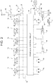
- FIG. 2 is a figure illustrating the schematic configuration of a hydraulic circuit included in the hydraulic excavator 1. Note that unless otherwise noted particularly, the front, rear, left and right directions in the present specification are relative to the viewpoint of an operator who gets on, and operates the hydraulic excavator 1.
- specific examples of the work machine are not limited to the hydraulic excavator 1, but may be a dump truck, a motor grader, a wheel loader, and the like.
- the hydraulic excavator 1 includes a undercarriage 2, and an upperstructure 3 supported by the undercarriage 2.
- the undercarriage 2 includes a pair of left and right crawlers 8.
- the pair of left and right crawlers 8 rotate independently by driving wheels 8c driven by hydraulic motors 8a and 8b (see FIG. 2 ). Thereby, the hydraulic excavator 1 can move forward and backward, and make turns.
- the upperstructure 3 is supported by the undercarriage 2 such that the upperstructure 3 can be swung by a swing motor 3a (see FIG. 2 ).
- the upperstructure 3 includes: a swing frame 5 that serves as a base; a cab (operator's seat) 7 arranged on the front left side of the swing frame 5; a front work device 4 attached vertically rotatably to the middle on the front side of the swing frame 5; a counter weight 6 arranged on the rear side of the swing frame 5; and an engine 10 that generates drive force for operating the hydraulic excavator 1.
- the front work device 4 includes: a boom 4a supported by the upperstructure 3 such that the boom 4a can face upward and downward; an arm 4b supported by the tip of the boom 4a such that the arm 4b can oscillate; a bucket 4c supported by the tip of the arm 4b such that the bucket 4c can oscillate; and hydraulic cylinders (actuators) 4d to 4f that drive the boom 4a, the arm 4b, and the bucket 4c. That is, the boom 4a is directly supported by the upperstructure 3, and the arm 4b and the bucket 4c are indirectly supported by the upperstructure 3.
- the counter weight 6 is for counterbalancing the weight of the front work device 4, and is an arc-shaped heavy object.
- the cab 7 has an internal space formed therein. An operator who operates the hydraulic excavator 1 gets in the internal space.
- the internal space of the cab 7 has operation devices (a steering, pedals, levers, switches, etc.) arranged therein.
- the operator operates the operation devices to give instructions to operate the hydraulic excavator 1. That is, by the operation devices being operated by the operator who got in the cab 7, the hydraulic excavator 1 is operated.
- the operation devices include actuator operation devices for causing the undercarriage 2 to travel, swinging the upperstructure 3 and operating the front work device 4, and lock operation devices that lock and unlock operation of the hydraulic excavator 1.
- the actuator operation devices include: travel levers (travel operation devices) 11 and 12 that operate the pair of left and right crawlers 8, respectively; a boom lever 13 that operates the boom 4a; an arm lever 14 that operates the arm 4b; a bucket lever 15 that operates the bucket 4c; and a swing lever 16 that swings the upperstructure 3.
- the lock operation devices include a gate lock lever 17 that switches the position of a lock valve 31 mentioned below.
- the forms of the actuator operation devices, and the lock operation devices are not limited to lever forms, but may be steering forms, pedal forms, switch forms, button forms, or the like.
- the boom lever 13, the arm lever 14, the bucket lever 15, and the swing lever 16 are in some cases collectively denoted as "work levers 13 to 16.”
- the actuator operation devices are connected to pilot valves 21, 22, 23, 24, 25 and 26.
- the pilot valves 21 to 26 output hydraulic fluids pressurized and fed by a hydraulic pump (pilot pump) 33 driven by the engine 10 from a hydraulic fluid tank 32 to a hydraulic control circuit 34 as pilot hydraulic fluids for operating the corresponding actuators 3a, 4d to 4f, and 8a to 8b.
- the flow rates of the pilot hydraulic fluids change in accordance with operation amounts of corresponding actuator control devices.
- the pressures (pilot pressures) of the pilot hydraulic fluids are one example of operation signals.
- the pilot valves 21 and 22 output pilot hydraulic fluids for driving the hydraulic motors 8a and 8b in accordance with operation amounts of the travel levers 11 and 12.
- the pilot valve 23 outputs a pilot hydraulic fluid for driving the boom cylinder 4d in accordance with an operation amount of the boom lever 13.
- the pilot valve 24 outputs a pilot hydraulic fluid for driving the arm cylinder 4e in accordance with an operation amount of the arm lever 14.
- the pilot valve 25 outputs a pilot hydraulic fluid for driving the bucket cylinder 4f in accordance with an operation amount of the bucket lever 15.
- the pilot valve 26 outputs a pilot hydraulic fluid for driving the swing motor 3a in accordance with an operation amount of the swing lever 16.
- the gate lock lever 17 is configured such that an operator can switch the gate lock lever 17 to a permission position for restricting operation of the actuators 3a, 4d to 4f, and 8a to 8b, and permitting an entrance of the operator to the cab 7, and a prohibition position for permitting operation of the actuators 3a, 4d to 4f, and 8a to 8b, and prohibiting an entrance of the operator to the cab 7.
- the gate lock lever 17 outputs, to a controller 50 (see FIG. 3 ), a release signal when the gate lock lever 17 is at the prohibition position, for example.
- the gate lock lever 17 is arranged between the entrance and seat of the cab 7, for example. Then, the gate lock lever 17 may be configured such that when the gate lock lever 17 is at the permission position, the operator is not prevented from getting in or out of the cab 7, and when the gate lock lever 17 is at the prohibition position, the operator is prevented from getting in or out of the cab 7. Thereby, it is possible to lower the possibility that an operator leaves the cab 7 while keeping the gate lock lever 17 at the prohibition position.
- the hydraulic control circuit 34 supplies, to the actuators 3a, 4d to 4f, and 8a to 8b, a hydraulic fluid delivered by a hydraulic pump 330 driven by the engine 10 in accordance with the pilot hydraulic fluids supplied from the pilot valves 21 to 26.
- the hydraulic control circuit 34 includes directional control valves that are provided between the hydraulic pump 33, and the actuators 3a, 4d to 4f, and 8a to 8b, for example, and switch the supply amounts and supply directions of the hydraulic fluid in accordance with the pilot hydraulic fluids.
- a plurality of the directional control valves are provided corresponding to the individual actuators 3a, 4d to 4f, and 8a to 8b, control the speeds of the corresponding actuators 3a, 4d to 4f, and 8a to 8b in accordance with the supply amount of the hydraulic fluid, and control the operation directions of the corresponding actuator 3a, 4d to 4f, and 8a to 8b in accordance with the supply direction of the hydraulic fluid.
- the specific configuration of the hydraulic control circuit 34 is already well-known, and so detailed explanation is omitted.
- the lock valve 31 is a solenoid valve switched to a lock position and a release position in accordance with control by the controller 50.
- the lock valve 31 When the lock valve 31 is at the lock position, the supply of the hydraulic fluid from the hydraulic pump 33 to the pilot valves 21 to 26 is interrupted.
- the lock valve 31 when the lock valve 31 is at the release position, the supply of the hydraulic fluid from the hydraulic pump 33 to the pilot valves 21 to 26 is permitted.
- the lock valve 31 is configured such that, for example, the lock valve 31 is initially at the lock position, and the lock valve 31 is switched to the release position only while a release signal is being output from the gate lock lever 17, and returns to the lock position if the output of the release signal is stopped.
- the hydraulic control circuit 34 is connected with a swing brake 35 that restricts and permits the swing of the upperstructure 3.
- the swing brake 35 includes, for example, a brake pad 36 that brakes a rotation axis 3b of the upperstructure 3, and a cylinder 37 that makes the brake pad 36 in and out of contact with the rotation axis 3b.
- the swing brake 35 is configured such that, by a parking release hydraulic fluid supplied from the hydraulic control circuit 34, the swing brake 35 can be switched to a state where it restricts the swing of the upperstructure 3 and to a state where it permits the swing of the upperstructure 3.
- the cylinder 37 restricts the swing of the upperstructure 3 by causing the brake pad 36 to abut against the rotation axis 3b by using the urging force of a coil spring 38 that is one example of an urging member.
- the cylinder 37 receives, at the rod chamber, the supply of the parking release hydraulic fluid from the hydraulic control circuit 34, the cylinder 37 separates the brake pad 36 from the rotation axis 3b against the urging force of the coil spring 38, and permits the swing of the upperstructure 3.
- the cylinder 37 stops receiving the supply of the parking release hydraulic fluid from the hydraulic control circuit 34, the cylinder 37 causes the brake pad 36 to abut against the rotation axis 3b again by using the urging force of the coil spring 38, and restricts the swing of the upperstructure 3.
- the swing brake 35 is a so-called negative brake that prevents an unintended swing of the upperstructure 3 while the hydraulic excavator 1 is stopped.
- the upperstructure 3 or the front work device 4 is operated while the swing of the upperstructure 3 is restricted, the upperstructure 3 receives an excessive load. In view of this, when the upperstructure 3 or the front work device 4 is operated, the swing brake 35 needs to be released.
- the hydraulic control circuit 34 supplies the parking release hydraulic fluid to the cylinder 37 while the gate lock lever 17 is at the prohibition position, and at least one of the work levers 13 to 16 is being operated (i.e. while the pilot hydraulic fluid is being output from at least one of the pilot valves 23 to 26). That is, the swing brake 35 permits the swing of the upperstructure 3 while the pilot hydraulic fluid is being supplied from at least one of the pilot valves 23 to 26.
- the hydraulic control circuit 34 stops the supply of the parking release hydraulic fluid while the gate lock lever 17 is at the permission position or while the gate lock lever 17 is at the prohibition position, and none of the work levers 13 to 16 is being operated (i.e. while the pilot hydraulic fluid is not output from any of the pilot valves 23 to 26) . That is, the swing brake 35 restricts the swing of the upperstructure 3 while the pilot hydraulic fluid is not output from any of the pilot valves 23 to 26.
- the hydraulic control circuit 34 starts supplying the parking release hydraulic fluid to the cylinder 37 immediately before the hydraulic fluid starts being supplied to the actuators 3a, and 4d to 4f. That is, if the work levers 13 to 16 are operated, the swing brake 35 is released immediately before the upperstructure 3 or the front work device 4 starts operating.
- FIG. 3 is a block diagram illustrating the configuration of the controller 50 included in the hydraulic excavator 1.
- the controller 50 acquires various types of signal output from the gate lock lever 17, a temperature sensor 41, a parking release pressure sensor 42, and a travel pilot pressure sensor 43, and controls the lock valve 31 and a notification device 44 on the basis of the acquired various types of signal.
- the temperature sensor 41 measures the temperature of the hydraulic fluid stored in the hydraulic fluid tank 32, and outputs a temperature signal indicating the temperature acquired through the measurement to the controller 50.
- the parking release pressure sensor 42 measures the pressure of the parking release hydraulic fluid supplied to the cylinder 37, and outputs a pressure signal indicating the pressure acquired through the measurement to the controller 50.
- the travel pilot pressure sensor 43 measures the pressures of the pilot hydraulic fluid output from the pilot valves 21 and 22, and outputs pressure signals indicating the pressures acquired through the measurement to the controller 50.
- pressure sensors that detect pilot pressures in the present invention include pressure sensors that detect pilot pressures according to operation amounts of the boom lever 13, the arm lever 14, the bucket lever 15, and the swing lever 16, in addition to the parking release pressure sensor 42 and the travel pilot pressure sensor 43.
- the notification device 44 is a device that notifies various types of information to an operator who gets on the cab 7. Although specific examples of the notification device 44 are not limited particularly, for example, the notification device 44 is a display that displays characters, images and videos, for example, a warning light, or a speaker that outputs sounds.
- the controller 50 includes a CPU (Central Processing Unit), a ROM (Read Only Memory), and a RAM (Random Access Memory) . It should be noted, however, that the specific configuration of the controller 50 is not limited to this, and the controller 50 may be realized by hardware such as an ASIC (Application Specific Integrated Circuit) or a FPGA (Field-Programmable Gate Array).
- ASIC Application Specific Integrated Circuit
- FPGA Field-Programmable Gate Array
- the controller 50 By the CPU reading out program codes stored on the ROM, and executing them, the controller 50 functions as a switching section 51, a decision-time correcting section 52, a deciding section 53, and a notification processing section 54 through cooperation between software and hardware.
- the RAM is used as a work area when the CPU executes the program.
- the switching section 51 controls the switch position of the lock valve 31. More specifically, in a case where the gate lock lever 17 is operated from the permission position for permitting an entrance of an operator into the operator's seat to the prohibition position for prohibiting an entrance of an operator into the operator's seat, the lock valve 31 is switched to the lock position for interrupting the supply of the pilot hydraulic fluid or to the release position for permitting the supply of the pilot hydraulic fluid on the basis of results from the deciding section 53 mentioned below, and also the lock valve 31 is switched to the release position or the lock position on the basis of results from the deciding section 53 mentioned below also in a case where the gate lock lever 17 is operated from the prohibition position to the permission position.
- the switching section 51 switches the lock valve 31 from the release position to the lock position in response to a lapse of first time t 1 after the lock valve 31 is switched to the release position. Furthermore, after the lock valve 31 is switched to the lock position after the elapse of the first time t 1 , the switching section 51 switches the lock valve 31 again from the lock position to the release position in response to a notification from the deciding section 53 that there is no unintended operation.
- the decision-time correcting section 52 corrects the value of the first time t 1 , and notifies the corrected first time t 1 to the switching section 51 and the deciding section 53.
- the initial value of the first time t 1 is 0.2 seconds, for example.
- the decision-time correcting section 52 increases the first time t 1 to be set, as the temperature of the hydraulic fluid indicated by the temperature signal lowers. This is because due to an increase of the viscosity of the hydraulic fluid that accompanies lowering of the temperature, the rising of the parking release pressure P 1 , and the travel pilot pressure P 2 mentioned below becomes slower.
- the deciding section 53 decides whether or not the actuator operation devices 11 to 16 are operated until the first time t 1 elapses after the lock valve 31 is switched to the release position (operation at this timing is denoted "unintended operation"). In other words, the deciding section 53 decides whether or not the pilot hydraulic fluid is output from at least one of the pilot valves 21 to 26 until the first time t 1 elapses after the lock valve 31 is switched to the release position. Then, the deciding section 53 notifies results of the decision to the switching section 51 and the notification processing section 54.
- the deciding section 53 decides that unintended operation has occurred in a case where the parking release pressure P 1 indicated by a pressure signal output from the parking release pressure sensor 42 becomes equal to or higher than a first threshold P th1 until the first time t 1 elapses after the lock valve 31 is switched to the release position.
- the deciding section 53 decides that unintended operation has not occurred in a case where the parking release pressure P 1 stayed lower than the first threshold P th1 until the first time t 1 elapses after the lock valve 31 is switched to the release position.
- the first threshold P th1 is set to a value (e.g. 1 MPa) that is sufficiently lower than a parking release pressure P pk (e.g. 4 MPa) necessary for releasing the swing brake 35.
- the deciding section 53 decides that unintended operation has occurred in a case where the travel pilot pressure P 2 indicated by a pressure signal output from the travel pilot pressure sensor 43 becomes equal to or higher than a second threshold P th2 until the first time t 1 elapses after the lock valve 31 is switched to the release position.
- the deciding section 53 decides that unintended operation has not occurred in a case where the travel pilot pressure P 2 stayed lower than the second threshold P th2 until the first time t 1 elapses after the lock valve 31 is switched to the release position.
- the second threshold P th2 is set to a value (e.g. 0.6 MPa) that is sufficiently lower than a travel pilot pressure P tv (e.g. up to 4 MPa) output from the pilot valves 21 and 22 at the time of operation of the travel levers 11 and 12.
- the notification processing section 54 In response to a decision by the deciding section 53 that unintended operation has occurred, the notification processing section 54 gives, through the notification device 44: a notification that unintended operation has occurred; a notification that the lock valve 31 is switched to the lock position in response to sensing of the occurrence of the unintended operation; a notification about how to switch the lock valve 31 from the lock position to the release position; or the like. That is, the notification processing section 54 may cause a display to display messages, turn on (flash) a warning light or cause a speaker to output sounds, for example.
- FIG. 4 is a flowchart of an unintended-operation control process executed by the controller 50.
- FIG. 5 is a time chart illustrating temporal changes of the position of the gate lock lever 17, the position of the lock valve 31, whether or not the work levers 13 to 16 are operated, the parking release pressure, whether or not the travel levers 11 and 12 are operated, and the travel pilot pressure. Note that it is assumed that the gate lock lever 17 is at the permission position and the lock valve 31 is at the lock position at the time point of the start of the unintended-operation control process.
- the switching section 51 monitors whether the gate lock lever 17 is operated from the permission position to the prohibition position (release operation) (S11). In response to an output of a release signal from the gate lock lever 17 at time t 10 in FIG. 5 , the switching section 51 determines that the gate lock lever 17 is operated from the permission position to the prohibition position. Then, in response to the operation of the gate lock lever 17 from the permission position to the prohibition position (S11: Yes), the switching section 51 switches the lock valve 31 from the lock position to the release position (S12).
- the decision-time correcting section 52 corrects the first time t 1 (S13).
- the specific method of correcting the first time t 1 is not particularly limited. For example, a table, a graph, a function or the like indicating the relationship between temperature and the first time t 1 is stored on the ROM, and the first time t 1 corresponding to the temperature indicated by the temperature signal may be acquired. Then, the decision-time correcting section 52 notifies the corrected first time t 1 to the switching section 51 and the deciding section 53.
- the deciding section 53 monitors the values of the parking release pressure P 1 and the travel pilot pressure P 2 (S14) . More specifically, the deciding section 53 repetitively executes a process of acquiring the parking release pressure P 1 indicated by a pressure signal of the parking release pressure sensor 42, and storing the acquired parking release pressure P 1 on the RAM. Similarly, the deciding section 53 repetitively executes a process of acquiring the travel pilot pressure P 2 indicated by a pressure signal of the travel pilot pressure sensor 43, and storing the acquired travel pilot pressure P 2 on the RAM.
- the switching section 51 switches the lock valve 31 from the release position to the lock position (S16). At this time, the gate lock lever 17 is kept at the prohibition position. That is, irrespective of the position of the gate lock lever 17, the switching section 51 switches the lock valve 31 to the lock position at Step S16.
- the deciding section 53 compares the parking release pressure P 1 stored on the RAM with the first threshold P th1 , and compares the travel pilot pressure P 2 stored on the RAM with the second threshold P th2 (S17).
- the first threshold P th1 and the second threshold P th2 are values predetermined through experiments, simulations or the like, for example, and are stored on the ROM.
- the parking release pressure P 1 and the travel pilot pressure P 2 stay at 0 MPa, and so the deciding section 53 decides that the parking release pressure P 1 is lower than the first threshold P th1 , and the travel pilot pressure P 2 is lower than the second threshold P th2 (S17: No). That is, the deciding section 53 decides that unintended operation has not occurred between time t 10 and time t 11 . Then, the deciding section 53 notifies the switching section 51 and the notification processing section 54 of results of the decision that unintended operation has not occurred.
- the switching section 51 waits without executing processes at and after Step S19.
- the second time t 2 is a predetermined length of time, for example, and is 0.2 seconds, for example. Note that the first time t 1 and the second time t 2 may have the same value or may have different values.
- the switching section 51 switches the lock valve 31 from the lock position to the release position (S19).
- the notification processing section 54 may not execute any particular process.
- the switching section 51 switches the lock valve 31 from the release position to the lock position. Then, the switching section 51 returns to Step S11 again, and monitors whether the gate lock lever 17 is operated from the permission position to the prohibition position (S11).
- the switching section 51 switches the lock valve 31 to the release position (S12), the decision-time correcting section 52 corrects the first time t 1 (S13), the deciding section 53 monitors the parking release pressure P 1 and the travel pilot pressure P 2 until the first time t 1 elapses (S14), and, in response to a lapse of the first time t 1 , the switching section 51 switches the lock valve 31 to the lock position (S15).
- the parking release pressure P 1 is detected by the parking release pressure sensor 42. Accordingly, the deciding section 53 decides that the parking release pressure P 1 has become equal to or higher than the first threshold P th1 during the first time t 1 (between time t 22 and time t 23 ), and notifies the switching section 51 and the notification processing section 54 of results of the decision that unintended operation has occurred (S17: Yes).
- the notification processing section 54 notifies the occurrence of the unintended operation through the notification device 44 (S20).
- the switching section 51 does not execute the processes of Steps S18 to S19, but monitors whether the gate lock lever 17 is operated from the prohibition position to the permission position (lock operation) (S21). That is, the lock valve 31 is kept at the lock position. Then, even if the second time t 2 elapses from time t 23 or operation of the work levers 13 to 16 ends at time t 24 , the lock valve 31 is kept at the lock position.
- Step S11 in response to operation of the gate lock lever 17 from the prohibition position to the permission position at time t 25 in FIG. 5 (S21: Yes), the switching section 51 returns to Step S11 again, and monitors whether the gate lock lever 17 is operated from the permission position to the prohibition position (S11). It should be noted, however, that the lock valve 31 is already at the lock position, and so the switching section 51 does not need to switch the lock valve 31.
- the switching section 51 switches the lock valve 31 to the release position (S12), the decision-time correcting section 52 corrects the first time t 1 (S13), the deciding section 53 monitors the parking release pressure P 1 and the travel pilot pressure P 2 until the first time t 1 elapses (S14), and, in response to a lapse of the first time t 1 , the switching section 51 switches the lock valve 31 to the lock position (S15).
- the travel pilot pressure P 2 is detected by the travel pilot pressure sensor 43. Accordingly, the deciding section 53 decides that the travel pilot pressure P 2 has become equal to or higher than the second threshold P th2 during the first time t 1 (between time t 32 and time t 33 ), and notifies the switching section 51 and the notification processing section 54 of results of the decision that unintended operation has occurred (S17: Yes).
- the parking release pressure P 1 rises instantaneously to 6 MPa; on the contrary, if the gate lock lever 17 is operated to the prohibition position while the travel levers 11 and 12 are being operated, the travel pilot pressure P 2 rises slowly. Accordingly, the first time t 1 is desirably set longer than a length of time necessary for the travel pilot pressure P 2 to rise from 0 MPa to the second threshold P th2 (0.6 MPa) .
- the notification processing section 54 notifies the occurrence of the unintended operation through the notification device 44 (S20).
- the switching section 51 does not execute the processes of Steps S18 to S19, but monitors whether the gate lock lever 17 is operated from the prohibition position to the permission position (S21). That is, the lock valve 31 is kept at the lock position. Then, even if the second time t 2 elapses from time t 33 or operation of the travel levers 11 and 12 ends at time t 34 , the lock valve 31 is kept at the lock position.
- Step S11 in response to operation of the gate lock lever 17 from the prohibition position to the permission position at time t 35 in FIG. 5 (S21: Yes), the switching section 51 returns to Step S11 again, and monitors whether the gate lock lever 17 is operated from the permission position to the prohibition position (S11). It should be noted, however, that the lock valve 31 is already at the lock position, and so the switching section 51 does not need to switch the lock valve 31. Explanation of the subsequent processes is similar to previously mentioned explanation, and so is not presented again.
- the lock valve 31 is switched to the release position only for the first time t 1 , and whether or not unintended operation has occurred is decided until the first time t 1 elapses. Then, if unintended operation has not occurred, the lock valve 31 is switched to the release position, and if unintended operation has occurred, the lock valve 31 is kept at the lock position.
- whether or not unintended operation of the work levers 13 to 16 has occurred is decided on the basis of the parking release pressure P 1 .
- the parking release pressure P 1 rises no matter which of the work levers 13 to 16 is operated. Accordingly, by detecting the parking release pressure P 1 at the parking release pressure sensor 42, the number of sensors can be reduced as compared with a case where a sensor is provided for each of the pilot valves 23 to 26.
- the rising of a detection signal of the parking release pressure P 1 is faster (the parking release pressure P 1 rises instantaneously) as compared with the rising of a detection signal of the pilot pressure due to operation of the work levers 13 to 16, and so whether or not unintended operation of the work lever 13 to 16 has occurred can be decided more promptly and surely.
- the rising of a detection signal of the parking release pressure P 1 is faster (the parking release pressure P 1 rises instantaneously) as compared with the rising of a detection signal of the pilot pressure due to operation of the work levers 13 to 16, and so whether or not unintended operation of the work lever 13 to 16 has occurred can be decided more promptly and surely.
- an occurrence of unintended operation is notified through the notification device 44 (S20). Furthermore, according to the embodiment described above, in a case where it is decided that unintended operation has occurred, in order to switch the lock valve 31 to the release position again, the operator needs to operate the gate lock lever 17 to the permission position once (S21: Yes), and to the prohibition position again (S11: Yes). By causing the operator to execute such a procedure, it is possible to make the operator aware of the occurrence of the unintended operation. As a result, it is possible to expect that the gate lock lever 17 is operated to the prohibition position after the unintended operation is dealt with.
Landscapes
- Engineering & Computer Science (AREA)
- General Engineering & Computer Science (AREA)
- Mining & Mineral Resources (AREA)
- Civil Engineering (AREA)
- Structural Engineering (AREA)
- Physics & Mathematics (AREA)
- Fluid Mechanics (AREA)
- Mechanical Engineering (AREA)
- Operation Control Of Excavators (AREA)
- Component Parts Of Construction Machinery (AREA)
Abstract
Description
- The present invention relates to a work machine capable of switching via a gate lock lever whether it is allowed to operate actuators.
-
Patent Literature 1 describes a work vehicle that enables prevention of unexpected operation of actuators due to unintended operation at the time of gate lock lever switching. The work vehicle described inPatent Literature 1 switches a lock valve from a locked state to a released state if a lock member is switched from a lock position to a release position, and switches the lock valve to the locked state in a case where a pilot pressure has become equal to or higher than a predetermined pressure in a predetermined length of time after the lock member is switched to the release position. - PATENT LITERATURE 1: Japanese Patent No.
5467176 - In the work vehicle described in
Patent Literature 1, whether or not unintended operation has occurred is detected while the lock valve is kept in the released state, and the lock valve is switched to the locked state again after unintended operation is detected. However, an inertial force is applied to an actuator having started operating, and so there is a possibility that even if the lock valve is switched to the locked state, the actuator does not stop immediately. - The present invention has been contrived in view of the circumstance described above, and an object thereof is to provide a work machine that can stop unexpected operation of actuators faster than it actually occurs even if unintended operation occurs at the time of gate lock lever switching that leads to such unexpected operation.
- In order to achieve the object, in a work machine of the present invention including: an engine; a hydraulic pump driven by the engine; an actuator driven by a hydraulic fluid delivered by the hydraulic pump; a directional control valve that is provided between the hydraulic pump and the actuator, and controls an operation direction of the actuator and a speed of the actuator; an actuator operation device that operates the actuator; a pilot valve that outputs, to the directional control valve and as an operation signal, a pilot pressure according to an operation amount of the actuator operation device; a lock operation device that can be operated to a permission position for permitting an entrance of an operator to an operator's seat, and a prohibition position for prohibiting an entrance of the operator to the operator's seat; a lock valve that is switched to a lock position for interrupting a supply of the hydraulic fluid to the pilot valve in a case where the lock operation device is operated to the permission position, and is switched to a release position for supplying the hydraulic fluid to the pilot valve in a case where the lock operation device is operated to the prohibition position; a pressure sensor that detects the pilot pressure; and a controller that controls a switch position of the lock valve, the controller switches the lock valve from the lock position to the release position in a case where the lock operation device is operated from the permission position to the prohibition position; decides, on the basis of a result of the detection by the pressure sensor, whether or not a pilot hydraulic fluid has been output from the pilot valve until first time elapses after the lock valve is switched to the release position; keeps the lock valve at the lock position if it is decided that the pilot hydraulic fluid has been output until the first time elapses; and switches the lock valve from the lock position to the release position if it is decided that the pilot hydraulic fluid has not been output until the first time elapses, and second time elapses.
- According to the present invention, it is possible to stop unexpected operation of actuators faster than it actually occurs even if unintended operation occurs at the time of gate lock lever switching that leads to such unexpected operation. Note that problems, configurations and effects other than those described above are made apparent by the following explanation of an embodiment.
-
- [
FIG. 1] FIG. 1 is a side view of a hydraulic excavator that is a representative example of a work machine according to the present invention. - [
FIG. 2] FIG. 2 is a figure illustrating the schematic configuration of a hydraulic circuit included in the hydraulic excavator. - [
FIG. 3] FIG. 3 is a block diagram illustrating the configuration of a controller included in the hydraulic excavator. - [
FIG. 4] FIG. 4 is a flowchart of an unintended-operation control process executed by the controller. - [
FIG. 5] FIG. 5 is a time chart illustrating temporal changes of the position of a gate lock lever, the position of a lock valve, operation of work levers, a parking release pressure, operation of travel levers, and a travel pilot pressure. - An embodiment of a work machine according to the present invention is explained by using the drawings.
FIG. 1 is a side view of ahydraulic excavator 1 that is a representative example of a work machine according to the present invention.FIG. 2 is a figure illustrating the schematic configuration of a hydraulic circuit included in thehydraulic excavator 1. Note that unless otherwise noted particularly, the front, rear, left and right directions in the present specification are relative to the viewpoint of an operator who gets on, and operates thehydraulic excavator 1. In addition, specific examples of the work machine are not limited to thehydraulic excavator 1, but may be a dump truck, a motor grader, a wheel loader, and the like. - The
hydraulic excavator 1 includes aundercarriage 2, and anupperstructure 3 supported by theundercarriage 2. Theundercarriage 2 includes a pair of left andright crawlers 8. The pair of left andright crawlers 8 rotate independently by driving wheels 8c driven byhydraulic motors FIG. 2 ). Thereby, thehydraulic excavator 1 can move forward and backward, and make turns. - The
upperstructure 3 is supported by theundercarriage 2 such that theupperstructure 3 can be swung by aswing motor 3a (seeFIG. 2 ). Theupperstructure 3 includes: aswing frame 5 that serves as a base; a cab (operator's seat) 7 arranged on the front left side of theswing frame 5; a front work device 4 attached vertically rotatably to the middle on the front side of theswing frame 5; acounter weight 6 arranged on the rear side of theswing frame 5; and anengine 10 that generates drive force for operating thehydraulic excavator 1. - The front work device 4 includes: a
boom 4a supported by theupperstructure 3 such that theboom 4a can face upward and downward; anarm 4b supported by the tip of theboom 4a such that thearm 4b can oscillate; a bucket 4c supported by the tip of thearm 4b such that the bucket 4c can oscillate; and hydraulic cylinders (actuators) 4d to 4f that drive theboom 4a, thearm 4b, and the bucket 4c. That is, theboom 4a is directly supported by theupperstructure 3, and thearm 4b and the bucket 4c are indirectly supported by theupperstructure 3. Thecounter weight 6 is for counterbalancing the weight of the front work device 4, and is an arc-shaped heavy object. - The
cab 7 has an internal space formed therein. An operator who operates thehydraulic excavator 1 gets in the internal space. The internal space of thecab 7 has operation devices (a steering, pedals, levers, switches, etc.) arranged therein. The operator operates the operation devices to give instructions to operate thehydraulic excavator 1. That is, by the operation devices being operated by the operator who got in thecab 7, thehydraulic excavator 1 is operated. The operation devices include actuator operation devices for causing theundercarriage 2 to travel, swinging theupperstructure 3 and operating the front work device 4, and lock operation devices that lock and unlock operation of thehydraulic excavator 1. - As illustrated in
FIG. 2 , the actuator operation devices include: travel levers (travel operation devices) 11 and 12 that operate the pair of left andright crawlers 8, respectively; aboom lever 13 that operates theboom 4a; anarm lever 14 that operates thearm 4b; abucket lever 15 that operates the bucket 4c; and aswing lever 16 that swings theupperstructure 3. The lock operation devices include agate lock lever 17 that switches the position of alock valve 31 mentioned below. - Note that the forms of the actuator operation devices, and the lock operation devices are not limited to lever forms, but may be steering forms, pedal forms, switch forms, button forms, or the like. In addition, in the following explanation, the boom lever 13, the
arm lever 14, thebucket lever 15, and theswing lever 16 are in some cases collectively denoted as "work levers 13 to 16." - The actuator operation devices are connected to
pilot valves pilot valves 21 to 26 output hydraulic fluids pressurized and fed by a hydraulic pump (pilot pump) 33 driven by theengine 10 from ahydraulic fluid tank 32 to ahydraulic control circuit 34 as pilot hydraulic fluids for operating thecorresponding actuators - More specifically, the
pilot valves hydraulic motors travel levers pilot valve 23 outputs a pilot hydraulic fluid for driving theboom cylinder 4d in accordance with an operation amount of theboom lever 13. Thepilot valve 24 outputs a pilot hydraulic fluid for driving thearm cylinder 4e in accordance with an operation amount of thearm lever 14. Thepilot valve 25 outputs a pilot hydraulic fluid for driving thebucket cylinder 4f in accordance with an operation amount of thebucket lever 15. Thepilot valve 26 outputs a pilot hydraulic fluid for driving theswing motor 3a in accordance with an operation amount of theswing lever 16. - The
gate lock lever 17 is configured such that an operator can switch thegate lock lever 17 to a permission position for restricting operation of theactuators cab 7, and a prohibition position for permitting operation of theactuators cab 7. The gate lock lever 17 outputs, to a controller 50 (seeFIG. 3 ), a release signal when thegate lock lever 17 is at the prohibition position, for example. - The
gate lock lever 17 is arranged between the entrance and seat of thecab 7, for example. Then, thegate lock lever 17 may be configured such that when thegate lock lever 17 is at the permission position, the operator is not prevented from getting in or out of thecab 7, and when thegate lock lever 17 is at the prohibition position, the operator is prevented from getting in or out of thecab 7. Thereby, it is possible to lower the possibility that an operator leaves thecab 7 while keeping thegate lock lever 17 at the prohibition position. - The
hydraulic control circuit 34 supplies, to theactuators hydraulic pump 330 driven by theengine 10 in accordance with the pilot hydraulic fluids supplied from thepilot valves 21 to 26. Thehydraulic control circuit 34 includes directional control valves that are provided between thehydraulic pump 33, and theactuators individual actuators corresponding actuators corresponding actuator hydraulic control circuit 34 is already well-known, and so detailed explanation is omitted. - The
lock valve 31 is a solenoid valve switched to a lock position and a release position in accordance with control by thecontroller 50. When thelock valve 31 is at the lock position, the supply of the hydraulic fluid from thehydraulic pump 33 to thepilot valves 21 to 26 is interrupted. On the other hand, when thelock valve 31 is at the release position, the supply of the hydraulic fluid from thehydraulic pump 33 to thepilot valves 21 to 26 is permitted. Thelock valve 31 is configured such that, for example, thelock valve 31 is initially at the lock position, and thelock valve 31 is switched to the release position only while a release signal is being output from thegate lock lever 17, and returns to the lock position if the output of the release signal is stopped. - That is, when the
gate lock lever 17 is at the permission position (thelock valve 31 is at the lock position), no pilot hydraulic fluids are output from thepilot valve 21 to 26 even if an actuator operation device is operated. In other words, when thegate lock lever 17 is at the permission position (thelock valve 31 is at the lock position), theactuators - On the other hand, when the
gate lock lever 17 is at the prohibition position (thelock valve 31 is at the release position), a pilot hydraulic fluid is output from thepilot valve 21 to 26 if an actuator operation device is operated. That is, when thegate lock lever 17 is at the prohibition position (thelock valve 31 is at the release position), theactuators - The
hydraulic control circuit 34 is connected with aswing brake 35 that restricts and permits the swing of theupperstructure 3. Theswing brake 35 includes, for example, abrake pad 36 that brakes arotation axis 3b of theupperstructure 3, and acylinder 37 that makes thebrake pad 36 in and out of contact with therotation axis 3b. Theswing brake 35 is configured such that, by a parking release hydraulic fluid supplied from thehydraulic control circuit 34, theswing brake 35 can be switched to a state where it restricts the swing of theupperstructure 3 and to a state where it permits the swing of theupperstructure 3. - The
cylinder 37 restricts the swing of theupperstructure 3 by causing thebrake pad 36 to abut against therotation axis 3b by using the urging force of acoil spring 38 that is one example of an urging member. In addition, if thecylinder 37 receives, at the rod chamber, the supply of the parking release hydraulic fluid from thehydraulic control circuit 34, thecylinder 37 separates thebrake pad 36 from therotation axis 3b against the urging force of thecoil spring 38, and permits the swing of theupperstructure 3. Furthermore, if thecylinder 37 stops receiving the supply of the parking release hydraulic fluid from thehydraulic control circuit 34, thecylinder 37 causes thebrake pad 36 to abut against therotation axis 3b again by using the urging force of thecoil spring 38, and restricts the swing of theupperstructure 3. - The
swing brake 35 is a so-called negative brake that prevents an unintended swing of theupperstructure 3 while thehydraulic excavator 1 is stopped. On the other hand, if theupperstructure 3 or the front work device 4 is operated while the swing of theupperstructure 3 is restricted, theupperstructure 3 receives an excessive load. In view of this, when theupperstructure 3 or the front work device 4 is operated, theswing brake 35 needs to be released. - In view of this, the
hydraulic control circuit 34 supplies the parking release hydraulic fluid to thecylinder 37 while thegate lock lever 17 is at the prohibition position, and at least one of the work levers 13 to 16 is being operated (i.e. while the pilot hydraulic fluid is being output from at least one of thepilot valves 23 to 26). That is, theswing brake 35 permits the swing of theupperstructure 3 while the pilot hydraulic fluid is being supplied from at least one of thepilot valves 23 to 26. - On the other hand, the
hydraulic control circuit 34 stops the supply of the parking release hydraulic fluid while thegate lock lever 17 is at the permission position or while thegate lock lever 17 is at the prohibition position, and none of the work levers 13 to 16 is being operated (i.e. while the pilot hydraulic fluid is not output from any of thepilot valves 23 to 26) . That is, theswing brake 35 restricts the swing of theupperstructure 3 while the pilot hydraulic fluid is not output from any of thepilot valves 23 to 26. - In addition, in order to release the
swing brake 35 before theupperstructure 3 or the front work device 4 actually starts moving, thehydraulic control circuit 34 starts supplying the parking release hydraulic fluid to thecylinder 37 immediately before the hydraulic fluid starts being supplied to theactuators swing brake 35 is released immediately before theupperstructure 3 or the front work device 4 starts operating. - Next, the configuration of the
controller 50 is explained with reference toFIG. 3. FIG. 3 is a block diagram illustrating the configuration of thecontroller 50 included in thehydraulic excavator 1. Thecontroller 50 acquires various types of signal output from thegate lock lever 17, atemperature sensor 41, a parkingrelease pressure sensor 42, and a travelpilot pressure sensor 43, and controls thelock valve 31 and anotification device 44 on the basis of the acquired various types of signal. - For example, the
temperature sensor 41 measures the temperature of the hydraulic fluid stored in thehydraulic fluid tank 32, and outputs a temperature signal indicating the temperature acquired through the measurement to thecontroller 50. The parkingrelease pressure sensor 42 measures the pressure of the parking release hydraulic fluid supplied to thecylinder 37, and outputs a pressure signal indicating the pressure acquired through the measurement to thecontroller 50. The travelpilot pressure sensor 43 measures the pressures of the pilot hydraulic fluid output from thepilot valves controller 50. - It is assumed that pressure sensors that detect pilot pressures in the present invention include pressure sensors that detect pilot pressures according to operation amounts of the
boom lever 13, thearm lever 14, thebucket lever 15, and theswing lever 16, in addition to the parkingrelease pressure sensor 42 and the travelpilot pressure sensor 43. - The
notification device 44 is a device that notifies various types of information to an operator who gets on thecab 7. Although specific examples of thenotification device 44 are not limited particularly, for example, thenotification device 44 is a display that displays characters, images and videos, for example, a warning light, or a speaker that outputs sounds. - Although an illustration is omitted, the
controller 50 includes a CPU (Central Processing Unit), a ROM (Read Only Memory), and a RAM (Random Access Memory) . It should be noted, however, that the specific configuration of thecontroller 50 is not limited to this, and thecontroller 50 may be realized by hardware such as an ASIC (Application Specific Integrated Circuit) or a FPGA (Field-Programmable Gate Array). - By the CPU reading out program codes stored on the ROM, and executing them, the
controller 50 functions as aswitching section 51, a decision-time correcting section 52, a decidingsection 53, and anotification processing section 54 through cooperation between software and hardware. In addition, the RAM is used as a work area when the CPU executes the program. - The switching
section 51 controls the switch position of thelock valve 31. More specifically, in a case where thegate lock lever 17 is operated from the permission position for permitting an entrance of an operator into the operator's seat to the prohibition position for prohibiting an entrance of an operator into the operator's seat, thelock valve 31 is switched to the lock position for interrupting the supply of the pilot hydraulic fluid or to the release position for permitting the supply of the pilot hydraulic fluid on the basis of results from the decidingsection 53 mentioned below, and also thelock valve 31 is switched to the release position or the lock position on the basis of results from the decidingsection 53 mentioned below also in a case where thegate lock lever 17 is operated from the prohibition position to the permission position. - In addition, the switching
section 51 switches thelock valve 31 from the release position to the lock position in response to a lapse of first time t1 after thelock valve 31 is switched to the release position. Furthermore, after thelock valve 31 is switched to the lock position after the elapse of the first time t1, the switchingsection 51 switches thelock valve 31 again from the lock position to the release position in response to a notification from the decidingsection 53 that there is no unintended operation. - On the basis of a temperature signal output from the
temperature sensor 41, the decision-time correcting section 52 corrects the value of the first time t1, and notifies the corrected first time t1 to theswitching section 51 and the decidingsection 53. The initial value of the first time t1 is 0.2 seconds, for example. Then, the decision-time correcting section 52 increases the first time t1 to be set, as the temperature of the hydraulic fluid indicated by the temperature signal lowers. This is because due to an increase of the viscosity of the hydraulic fluid that accompanies lowering of the temperature, the rising of the parking release pressure P1, and the travel pilot pressure P2 mentioned below becomes slower. - The deciding
section 53 decides whether or not theactuator operation devices 11 to 16 are operated until the first time t1 elapses after thelock valve 31 is switched to the release position (operation at this timing is denoted "unintended operation"). In other words, the decidingsection 53 decides whether or not the pilot hydraulic fluid is output from at least one of thepilot valves 21 to 26 until the first time t1 elapses after thelock valve 31 is switched to the release position. Then, the decidingsection 53 notifies results of the decision to theswitching section 51 and thenotification processing section 54. - Note that typical examples of "unintended operation" in the present embodiment include operation of the
gate lock lever 17 from the permission position to the prohibition position while theactuator operation devices 11 to 16 are being operated. For example, it can be assumed that an operator operates thegate lock lever 17 while the operator does not notice that his/her body hits theactuator operation devices 11 to 16 and theactuator operation device 11 to 16 are being operated. - As one example, the deciding
section 53 decides that unintended operation has occurred in a case where the parking release pressure P1 indicated by a pressure signal output from the parkingrelease pressure sensor 42 becomes equal to or higher than a first threshold Pth1 until the first time t1 elapses after thelock valve 31 is switched to the release position. On the other hand, the decidingsection 53 decides that unintended operation has not occurred in a case where the parking release pressure P1 stayed lower than the first threshold Pth1 until the first time t1 elapses after thelock valve 31 is switched to the release position. Note that the first threshold Pth1 is set to a value (e.g. 1 MPa) that is sufficiently lower than a parking release pressure Ppk (e.g. 4 MPa) necessary for releasing theswing brake 35. - As another example, the deciding
section 53 decides that unintended operation has occurred in a case where the travel pilot pressure P2 indicated by a pressure signal output from the travelpilot pressure sensor 43 becomes equal to or higher than a second threshold Pth2 until the first time t1 elapses after thelock valve 31 is switched to the release position. On the other hand, the decidingsection 53 decides that unintended operation has not occurred in a case where the travel pilot pressure P2 stayed lower than the second threshold Pth2 until the first time t1 elapses after thelock valve 31 is switched to the release position. Note that the second threshold Pth2 is set to a value (e.g. 0.6 MPa) that is sufficiently lower than a travel pilot pressure Ptv (e.g. up to 4 MPa) output from thepilot valves - In response to a decision by the deciding
section 53 that unintended operation has occurred, thenotification processing section 54 gives, through the notification device 44: a notification that unintended operation has occurred; a notification that thelock valve 31 is switched to the lock position in response to sensing of the occurrence of the unintended operation; a notification about how to switch thelock valve 31 from the lock position to the release position; or the like. That is, thenotification processing section 54 may cause a display to display messages, turn on (flash) a warning light or cause a speaker to output sounds, for example. - Next, a process of the
controller 50 is explained with reference toFIG. 4 andFIG. 5 .FIG. 4 is a flowchart of an unintended-operation control process executed by thecontroller 50.FIG. 5 is a time chart illustrating temporal changes of the position of thegate lock lever 17, the position of thelock valve 31, whether or not the work levers 13 to 16 are operated, the parking release pressure, whether or not the travel levers 11 and 12 are operated, and the travel pilot pressure. Note that it is assumed that thegate lock lever 17 is at the permission position and thelock valve 31 is at the lock position at the time point of the start of the unintended-operation control process. - First, the switching
section 51 monitors whether thegate lock lever 17 is operated from the permission position to the prohibition position (release operation) (S11). In response to an output of a release signal from thegate lock lever 17 at time t10 inFIG. 5 , the switchingsection 51 determines that thegate lock lever 17 is operated from the permission position to the prohibition position. Then, in response to the operation of thegate lock lever 17 from the permission position to the prohibition position (S11: Yes), the switchingsection 51 switches thelock valve 31 from the lock position to the release position (S12). - Next, on the basis of a temperature signal output from the
temperature sensor 41, the decision-time correcting section 52 corrects the first time t1 (S13). The specific method of correcting the first time t1 is not particularly limited. For example, a table, a graph, a function or the like indicating the relationship between temperature and the first time t1 is stored on the ROM, and the first time t1 corresponding to the temperature indicated by the temperature signal may be acquired. Then, the decision-time correcting section 52 notifies the corrected first time t1 to theswitching section 51 and the decidingsection 53. - Next, until the first time t1 elapses after the
gate lock lever 17 is operated to the prohibition position (S15: No), the decidingsection 53 monitors the values of the parking release pressure P1 and the travel pilot pressure P2 (S14) . More specifically, the decidingsection 53 repetitively executes a process of acquiring the parking release pressure P1 indicated by a pressure signal of the parkingrelease pressure sensor 42, and storing the acquired parking release pressure P1 on the RAM. Similarly, the decidingsection 53 repetitively executes a process of acquiring the travel pilot pressure P2 indicated by a pressure signal of the travelpilot pressure sensor 43, and storing the acquired travel pilot pressure P2 on the RAM. - Next, in response to a lapse of the time t1 after the
gate lock lever 17 is operated to the prohibition position (time t11 has come inFIG. 5 ) (S15: Yes), the switchingsection 51 switches thelock valve 31 from the release position to the lock position (S16). At this time, thegate lock lever 17 is kept at the prohibition position. That is, irrespective of the position of thegate lock lever 17, the switchingsection 51 switches thelock valve 31 to the lock position at Step S16. - In addition, in response to a lapse of the time t1 after the
gate lock lever 17 is operated to the prohibition position (S15: Yes), the decidingsection 53 compares the parking release pressure P1 stored on the RAM with the first threshold Pth1, and compares the travel pilot pressure P2 stored on the RAM with the second threshold Pth2 (S17). The first threshold Pth1 and the second threshold Pth2 are values predetermined through experiments, simulations or the like, for example, and are stored on the ROM. - Between time t10 and time t11 in
FIG. 5 , the parking release pressure P1 and the travel pilot pressure P2 stay at 0 MPa, and so the decidingsection 53 decides that the parking release pressure P1 is lower than the first threshold Pth1, and the travel pilot pressure P2 is lower than the second threshold Pth2 (S17: No). That is, the decidingsection 53 decides that unintended operation has not occurred between time t10 and time t11. Then, the decidingsection 53 notifies theswitching section 51 and thenotification processing section 54 of results of the decision that unintended operation has not occurred. - Next, in response to the decision by the deciding
section 53 that unintended operation has not occurred between time t10 and time t11 (S17: No), until second time t2 elapses (S18: No), the switchingsection 51 waits without executing processes at and after Step S19. The second time t2 is a predetermined length of time, for example, and is 0.2 seconds, for example. Note that the first time t1 and the second time t2 may have the same value or may have different values. - Then, in response to a lapse of the second time t2 from time t11 (time t12 has come in
FIG. 5 ) (S18: Yes), the switchingsection 51 switches thelock valve 31 from the lock position to the release position (S19). On the other hand, in a case where the decidingsection 53 decides that unintended operation has not occurred between time t10 and time t11, thenotification processing section 54 may not execute any particular process. - Thereafter, if the work levers 13 to 16 are operated between time t13 and time t14, the parking release pressure P1 is detected, and the
actuators actuators - Next, if the operator operates the
gate lock lever 17 from the prohibition position to the permission position at time t20 inFIG. 5 , the switchingsection 51 switches thelock valve 31 from the release position to the lock position. Then, the switchingsection 51 returns to Step S11 again, and monitors whether thegate lock lever 17 is operated from the permission position to the prohibition position (S11). - Next, even if the operator operates the work levers 13 to 16 at time t21 in
FIG. 5 , the pilot hydraulic fluid is not output from thepilot valves 23 to 26 because thelock valve 31 is at the lock position, and also the parking release pressure P1 is not detected at the parkingrelease pressure sensor 42. Note that it is assumed in this example that the state where the work levers 13 to 16 are operated continues from time t21 to time t24. - Next, if the operator operates the
gate lock lever 17 from the permission position to the prohibition position at time t22 inFIG. 5 (S11: Yes), the switchingsection 51 switches thelock valve 31 to the release position (S12), the decision-time correcting section 52 corrects the first time t1 (S13), the decidingsection 53 monitors the parking release pressure P1 and the travel pilot pressure P2 until the first time t1 elapses (S14), and, in response to a lapse of the first time t1, the switchingsection 51 switches thelock valve 31 to the lock position (S15). - If the
lock valve 31 is switched to the lock position at time t23 inFIG. 5 , the parking release pressure P1 is no longer detected even if the work levers 13 to 16 remain being operated. Explanation of the processes of Steps S12 to S15 is similar to previously mentioned explanation, and so is not presented again. - If the
gate lock lever 17 is operated to the prohibition position at time t22 while the work levers 13 to 16 are being operated, the parking release pressure P1 is detected by the parkingrelease pressure sensor 42. Accordingly, the decidingsection 53 decides that the parking release pressure P1 has become equal to or higher than the first threshold Pth1 during the first time t1 (between time t22 and time t23), and notifies theswitching section 51 and thenotification processing section 54 of results of the decision that unintended operation has occurred (S17: Yes). - Next, in response to the decision by the deciding
section 53 that unintended operation has occurred between time t22 and time t23 (S17: Yes), thenotification processing section 54 notifies the occurrence of the unintended operation through the notification device 44 (S20). - On the other hand, in response to the decision by the deciding
section 53 that unintended operation has occurred between time t22 and time t23 (S17: Yes), the switchingsection 51 does not execute the processes of Steps S18 to S19, but monitors whether thegate lock lever 17 is operated from the prohibition position to the permission position (lock operation) (S21). That is, thelock valve 31 is kept at the lock position. Then, even if the second time t2 elapses from time t23 or operation of the work levers 13 to 16 ends at time t24, thelock valve 31 is kept at the lock position. - Next, in response to operation of the
gate lock lever 17 from the prohibition position to the permission position at time t25 inFIG. 5 (S21: Yes), the switchingsection 51 returns to Step S11 again, and monitors whether thegate lock lever 17 is operated from the permission position to the prohibition position (S11). It should be noted, however, that thelock valve 31 is already at the lock position, and so the switchingsection 51 does not need to switch thelock valve 31. - Next, even if the operator operates the travel levers 11 and 12 at time t31 in
FIG. 5 , the pilot hydraulic fluid is not output from thepilot valves lock valve 31 is at the lock position, and also the travel pilot pressure P2 is not detected at the travelpilot pressure sensor 43. Note that it is assumed in this example that the state where the travel levers 11 and 12 are operated continues from time t31 to time t34. - Next, if the operator operates the
gate lock lever 17 from the permission position to the prohibition position at time t32 inFIG. 5 (S11: Yes), the switchingsection 51 switches thelock valve 31 to the release position (S12), the decision-time correcting section 52 corrects the first time t1 (S13), the decidingsection 53 monitors the parking release pressure P1 and the travel pilot pressure P2 until the first time t1 elapses (S14), and, in response to a lapse of the first time t1, the switchingsection 51 switches thelock valve 31 to the lock position (S15). - If the
lock valve 31 is switched to the lock position at time t32 inFIG. 5 , the travel pilot pressure P2 is no longer detected even if the travel levers 11 and 12 remain being operated. Explanation of the processes of Steps S12 to S15 is similar to previously mentioned explanation, and so is not presented again. - If the
gate lock lever 17 is operated to the prohibition position at time t32 while the travel levers 11 and 12 are being operated, the travel pilot pressure P2 is detected by the travelpilot pressure sensor 43. Accordingly, the decidingsection 53 decides that the travel pilot pressure P2 has become equal to or higher than the second threshold Pth2 during the first time t1 (between time t32 and time t33), and notifies theswitching section 51 and thenotification processing section 54 of results of the decision that unintended operation has occurred (S17: Yes). - Note that if the
gate lock lever 17 is operated to the prohibition position while the work levers 13 to 16 are being operated as illustrated inFIG. 5 , the parking release pressure P1 rises instantaneously to 6 MPa; on the contrary, if thegate lock lever 17 is operated to the prohibition position while the travel levers 11 and 12 are being operated, the travel pilot pressure P2 rises slowly. Accordingly, the first time t1 is desirably set longer than a length of time necessary for the travel pilot pressure P2 to rise from 0 MPa to the second threshold Pth2 (0.6 MPa) . - Next, in response to the decision by the deciding
section 53 that unintended operation has occurred between time t32 and time t33 (S17: Yes), thenotification processing section 54 notifies the occurrence of the unintended operation through the notification device 44 (S20). - On the other hand, in response to the decision by the deciding
section 53 that unintended operation has occurred between time t32 and time t33 (S17: Yes), the switchingsection 51 does not execute the processes of Steps S18 to S19, but monitors whether thegate lock lever 17 is operated from the prohibition position to the permission position (S21). That is, thelock valve 31 is kept at the lock position. Then, even if the second time t2 elapses from time t33 or operation of the travel levers 11 and 12 ends at time t34, thelock valve 31 is kept at the lock position. - Next, in response to operation of the
gate lock lever 17 from the prohibition position to the permission position at time t35 inFIG. 5 (S21: Yes), the switchingsection 51 returns to Step S11 again, and monitors whether thegate lock lever 17 is operated from the permission position to the prohibition position (S11). It should be noted, however, that thelock valve 31 is already at the lock position, and so the switchingsection 51 does not need to switch thelock valve 31. Explanation of the subsequent processes is similar to previously mentioned explanation, and so is not presented again. - The embodiment described above provides the following action and effects, for example.
- In the embodiment described above, if the
gate lock lever 17 is operated to the prohibition position, thelock valve 31 is switched to the release position only for the first time t1, and whether or not unintended operation has occurred is decided until the first time t1 elapses. Then, if unintended operation has not occurred, thelock valve 31 is switched to the release position, and if unintended operation has occurred, thelock valve 31 is kept at the lock position. Thereby, as compared with a case where whether or not unintended operation has occurred is decided with thelock valve 31 being kept at the release position, and thelock valve 31 is switched to the lock position if it is decided that unintended operation has occurred, it is possible to stop unexpected operation of theactuators - In addition, as the temperature lowers, the viscosity of the hydraulic fluid becomes higher, and so the rising of the travel pilot pressure P2 in particular becomes slower. In view of this, by making longer the time (first time) t1 for a decision about the travel pilot pressure P2 at Steps S14 to S15 as the temperature of the hydraulic fluid lowers as in the embodiment described above, it is possible to decide fast whether or not unintended operation has occurred.
- In addition, according to the embodiment described above, whether or not unintended operation of the work levers 13 to 16 has occurred is decided on the basis of the parking release pressure P1. The parking release pressure P1 rises no matter which of the work levers 13 to 16 is operated. Accordingly, by detecting the parking release pressure P1 at the parking
release pressure sensor 42, the number of sensors can be reduced as compared with a case where a sensor is provided for each of thepilot valves 23 to 26. In addition, the rising of a detection signal of the parking release pressure P1 is faster (the parking release pressure P1 rises instantaneously) as compared with the rising of a detection signal of the pilot pressure due to operation of the work levers 13 to 16, and so whether or not unintended operation of thework lever 13 to 16 has occurred can be decided more promptly and surely. As a result, for example, it is possible to prevent more surely theupperstructure 3 from rotating due to inertia. - In addition, according to the embodiment described above, an occurrence of unintended operation is notified through the notification device 44 (S20). Furthermore, according to the embodiment described above, in a case where it is decided that unintended operation has occurred, in order to switch the
lock valve 31 to the release position again, the operator needs to operate thegate lock lever 17 to the permission position once (S21: Yes), and to the prohibition position again (S11: Yes). By causing the operator to execute such a procedure, it is possible to make the operator aware of the occurrence of the unintended operation. As a result, it is possible to expect that thegate lock lever 17 is operated to the prohibition position after the unintended operation is dealt with. - The embodiment mentioned above is illustrated for the purpose of explaining the present invention, and it is not intended to limit the scope of the present invention only to the embodiment. Those skilled in the art can implement the present invention in various other aspects without deviating from the gist of the present invention.
-
- 1...
- hydraulic excavator,
- 2...
- undercarriage,
- 3...
- upperstructure,
- 3a...
- swing motor,
- 4...
- front work device,
- 4a...
- boom,
- 4b...
- arm,
- 4c...
- bucket,
- 4d...
- boom cylinder,
- 4e...
- arm cylinder,
- 4f...
- bucket cylinder,
- 5...
- swing frame,
- 6...
- counter weight,
- 7...
- cab,
- 8...
- crawler,
- 8a, 8b...
- hydraulic motor,
- 8c...
- driving wheel,
- 10...
- engine,
- 11, 12...
- travel lever (travel operation device),
- 13...
- boom lever,
- 14...
- arm lever,
- 15...
- bucket lever,
- 16...
- swing lever,
- 17...
- gate lock lever (lock operation device),
- 21, 22, 23, 24, 25, 26...
- pilot valve,
- 31...
- lock valve,
- 32...
- hydraulic fluid tank,
- 33...
- hydraulic pump,
- 34...
- hydraulic control circuit,
- 35...
- swing brake,
- 36...
- brake pad,
- 37...
- cylinder,
- 38...
- coil spring,
- 41...
- temperature sensor,
- 42...
- parking release pressure sensor,
- 43...
- travel pilot pressure sensor,
- 44...
- notification device,
- 50...
- controller,
- 51...
- switching section,
- 52...
- decision-time correcting section,
- 53...
- deciding section,
- 54...
- notification processing section
Claims (6)
- A work machine comprising:an engine;a hydraulic pump driven by the engine;an actuator driven by a hydraulic fluid delivered by the hydraulic pump;a directional control valve that is provided between the hydraulic pump and the actuator, and controls an operation direction of the actuator and a speed of the actuator;an actuator operation device that operates the actuator;a pilot valve that outputs, to the directional control valve and as an operation signal, a pilot pressure according to an operation amount of the actuator operation device;a lock operation device that can be operated to a permission position for permitting an entrance of an operator to an operator's seat, and a prohibition position for prohibiting an entrance of the operator to the operator's seat;a lock valve that is switched to a lock position for interrupting a supply of the hydraulic fluid to the pilot valve in a case where the lock operation device is operated to the permission position, and is switched to a release position for supplying the hydraulic fluid to the pilot valve in a case where the lock operation device is operated to the prohibition position;a pressure sensor that detects the pilot pressure; anda controller that controls a switch position of the lock valve,wherein the controllerswitches the lock valve from the lock position to the release position in a case where the lock operation device is operated from the permission position to the prohibition position;decides, on the basis of a result of the detection by the pressure sensor, whether or not a pilot hydraulic fluid has been output from the pilot valve until first time elapses after the lock valve is switched to the release position;keeps the lock valve at the lock position if it is decided that the pilot hydraulic fluid has been output until the first time elapses; andswitches the lock valve from the lock position to the release position if it is decided that the pilot hydraulic fluid has not been output until the first time elapses, and second time elapses.
- The work machine according to claim 1, comprising a temperature sensor that detects a temperature of the hydraulic fluid supplied to the pilot valve,
wherein the controller increases the first time to be set, as the temperature detected by the temperature sensor becomes lower. - The work machine according to claim 1,
wherein the actuator includes a first actuator and a second actuator directly or indirectly supported by a swingable upperstructure,
the actuator operation device includes:a first operation device that operates the first actuator; anda second operation device that operates the second actuator,the pilot valve includes:a first pilot valve that outputs, to the directional control valve and as an operation signal, the pilot hydraulic fluid according to an operation amount of the first operation device; anda second pilot valve that outputs, to the directional control valve and as an operation signal, the pilot hydraulic fluid according to an operation amount of the second operation device,the work machine includes a swing brake that restricts a swing of the upperstructure by not receiving a supply of a parking release hydraulic fluid when neither the first pilot valve nor the second pilot valve is outputting the pilot hydraulic fluids, and permits a swing of the upperstructure by receiving a supply of the parking release hydraulic fluid when at least one of the first pilot valve and the second pilot valve is outputting the pilot hydraulic fluid,
the pressure sensor includes a parking release pressure sensor that detects a pressure of the parking release hydraulic fluid supplied to the swing brake, and
the controller decides that the pilot hydraulic fluid is being output from the pilot valve in response to the pressure detected by the parking release pressure sensor being equal to or higher than a first threshold. - The work machine according to claim 3,
wherein the actuator includes a travel actuator that causes the work machine to travel,
the actuator operation device includes a travel operation device that operates the travel actuator,
the pilot valve includes a travel pilot valve that outputs, to the directional control valve and as an operation signal, the pilot hydraulic fluid according to an operation amount of the travel operation device,
the pressure sensor includes a travel pilot pressure sensor that detects a pressure of the pilot hydraulic fluid output from the travel pilot valve, and
the controller decides that the pilot hydraulic fluid is being output from the pilot valve in response to the pressure detected by the travel pilot pressure sensor being equal to or higher than a second threshold. - The work machine according to claim 1,
wherein in a case where the controller decides that the pilot hydraulic fluid is output, and switches the lock valve to the lock position, if the lock operation device is operated from the prohibition position to the permission position, and furthermore the lock operation device is operated from the permission position to the prohibition position, the controller switches the lock valve from the lock position to the release position. - The work machine according to claim 1,
wherein the controller notifies an operator of unintended operation of the actuator operation device in response to a decision that the pilot hydraulic fluid is output.
Applications Claiming Priority (2)
| Application Number | Priority Date | Filing Date | Title |
|---|---|---|---|
| JP2018181967A JP7080783B2 (en) | 2018-09-27 | 2018-09-27 | Work machine |
| PCT/JP2019/038009 WO2020067366A1 (en) | 2018-09-27 | 2019-09-26 | Work machine |
Publications (2)
| Publication Number | Publication Date |
|---|---|
| EP3751059A1 true EP3751059A1 (en) | 2020-12-16 |
| EP3751059A4 EP3751059A4 (en) | 2021-11-24 |
Family
ID=69950690
Family Applications (1)
| Application Number | Title | Priority Date | Filing Date |
|---|---|---|---|
| EP19867510.0A Pending EP3751059A4 (en) | 2018-09-27 | 2019-09-26 | Work machine |
Country Status (6)
| Country | Link |
|---|---|
| US (1) | US11041290B2 (en) |
| EP (1) | EP3751059A4 (en) |
| JP (1) | JP7080783B2 (en) |
| KR (1) | KR102478478B1 (en) |
| CN (1) | CN111801470B (en) |
| WO (1) | WO2020067366A1 (en) |
Families Citing this family (7)
| Publication number | Priority date | Publication date | Assignee | Title |
|---|---|---|---|---|
| CN114008277B (en) * | 2019-08-08 | 2023-08-29 | 住友建机株式会社 | Excavator |
| JPWO2021241591A1 (en) * | 2020-05-25 | 2021-12-02 | ||
| JP7050981B1 (en) * | 2021-03-09 | 2022-04-08 | 日立建機株式会社 | Work machine |
| US20240125091A1 (en) * | 2021-03-31 | 2024-04-18 | Hitachi Construction Machinery Co., Ltd. | Construction Machine |
| WO2023132175A1 (en) * | 2022-01-05 | 2023-07-13 | 株式会社クボタ | Hydraulic system for work machine, and work machine |
| US12241227B2 (en) * | 2022-08-26 | 2025-03-04 | Caterpillar Sarl | System, method, and machine for engine restarting by joystick operation |
| CN116791702B (en) * | 2023-06-27 | 2025-08-29 | 上海华兴数字科技有限公司 | Hydraulic working machine control method, hydraulic working machine, equipment and storage medium |
Family Cites Families (13)
| Publication number | Priority date | Publication date | Assignee | Title |
|---|---|---|---|---|
| JPH0826885B2 (en) * | 1987-03-27 | 1996-03-21 | 日立建機株式会社 | Drive controller for hydraulic machine |
| JP2946495B2 (en) * | 1991-01-31 | 1999-09-06 | 株式会社小松製作所 | Safety unlocking system for construction vehicles |
| JPH0863248A (en) * | 1994-08-19 | 1996-03-08 | Hitachi Constr Mach Co Ltd | Misoperation prevention device for operating device |
| US5632190A (en) * | 1995-05-26 | 1997-05-27 | Hitachi Construction Machinery Co., Ltd. | Burglarproof device for hydraulic machine |
| KR0165960B1 (en) * | 1996-09-16 | 1999-10-01 | 대우중공업주식회사 | Loader pedal locker |
| DE602006008890D1 (en) * | 2005-01-11 | 2009-10-15 | Komatsu Mfg Co Ltd | LOCK CONTROL SYSTEM AND METHOD FOR WORKING MACHINE, WORKING MACHINE, LOCK CONTROL DEVICE AND LOCK CONTROL MANAGEMENT DEVICE FOR WORK MACHINERY |
| KR100919436B1 (en) * | 2008-06-03 | 2009-09-29 | 볼보 컨스트럭션 이키프먼트 홀딩 스웨덴 에이비 | Torque control system of plural variable displacement hydraulic pump and method thereof |
| JP5271758B2 (en) * | 2009-03-11 | 2013-08-21 | 日立建機株式会社 | Hydraulic drive device for work machine |
| JP5683361B2 (en) * | 2011-04-01 | 2015-03-11 | 日立建機株式会社 | Hydraulic drive device for work machine |
| US8833068B2 (en) | 2012-05-28 | 2014-09-16 | Komatsu Ltd. | Work vehicle and work vehicle control method |
| WO2015011832A1 (en) * | 2013-07-26 | 2015-01-29 | 株式会社小松製作所 | Work vehicle and work vehicle control method |
| JP6605519B2 (en) * | 2017-02-03 | 2019-11-13 | 日立建機株式会社 | Construction machinery |
| EP3587675B1 (en) * | 2017-02-22 | 2024-06-05 | Sumitomo (S.H.I.) Construction Machinery Co., Ltd. | Excavator |
-
2018
- 2018-09-27 JP JP2018181967A patent/JP7080783B2/en active Active
-
2019
- 2019-09-26 KR KR1020207025229A patent/KR102478478B1/en active Active
- 2019-09-26 CN CN201980016682.6A patent/CN111801470B/en active Active
- 2019-09-26 US US16/979,423 patent/US11041290B2/en active Active
- 2019-09-26 WO PCT/JP2019/038009 patent/WO2020067366A1/en not_active Ceased
- 2019-09-26 EP EP19867510.0A patent/EP3751059A4/en active Pending
Also Published As
| Publication number | Publication date |
|---|---|
| KR102478478B1 (en) | 2022-12-19 |
| US11041290B2 (en) | 2021-06-22 |
| JP2020051134A (en) | 2020-04-02 |
| WO2020067366A1 (en) | 2020-04-02 |
| EP3751059A4 (en) | 2021-11-24 |
| CN111801470B (en) | 2022-02-25 |
| US20210079624A1 (en) | 2021-03-18 |
| CN111801470A (en) | 2020-10-20 |
| JP7080783B2 (en) | 2022-06-06 |
| KR20200111816A (en) | 2020-09-29 |
Similar Documents
| Publication | Publication Date | Title |
|---|---|---|
| US11041290B2 (en) | Locking system for a work machine | |
| US10024032B2 (en) | Work machine | |
| JP2009202743A (en) | Controller for industrial vehicle and industrial vehicle having the same | |
| CN104520516B (en) | Work vehicle and control method for work vehicle | |
| JP6601437B2 (en) | Lane departure control device | |
| JP5005016B2 (en) | Driving vibration control device for work vehicle | |
| CN108178106B (en) | Industrial vehicle | |
| CN108291635A (en) | Work machine | |
| US20250369205A1 (en) | Work machine and control method for work machine | |
| CN114302995B (en) | construction machinery | |
| JP7328082B2 (en) | construction machinery | |
| EP4122802A1 (en) | Work machine and method for controlling work machine | |
| JP7577896B2 (en) | Construction Machinery | |
| JPH08218415A (en) | Driver's cab interference prevention device for hydraulic excavator and hydraulic excavator | |
| KR20120070074A (en) | Electric power steering apparatus control system and driver warning and vehicle speed control method according to steering speed for electric power steering apparatus using the same | |
| JP2018201419A (en) | Work vehicle stopping system and work vehicle including the same | |
| JP2022153119A (en) | construction machinery | |
| CN115123275B (en) | Vehicle control device | |
| JP7581152B2 (en) | Hydraulic system of work machine, work machine | |
| JP2003019969A (en) | By-wire steering system | |
| EP4549288A1 (en) | Work machine and method for controlling work machine | |
| JP7138089B2 (en) | work vehicle | |
| US20150032327A1 (en) | Drive shaft detection for pump or motor protection | |
| JP2026043871A (en) | Work machine and work machine control method | |
| JP6455191B2 (en) | Hydraulic motor control device and work vehicle |
Legal Events
| Date | Code | Title | Description |
|---|---|---|---|
| STAA | Information on the status of an ep patent application or granted ep patent |
Free format text: STATUS: THE INTERNATIONAL PUBLICATION HAS BEEN MADE |
|
| PUAI | Public reference made under article 153(3) epc to a published international application that has entered the european phase |
Free format text: ORIGINAL CODE: 0009012 |
|
| STAA | Information on the status of an ep patent application or granted ep patent |
Free format text: STATUS: REQUEST FOR EXAMINATION WAS MADE |
|
| 17P | Request for examination filed |
Effective date: 20200910 |
|
| AK | Designated contracting states |
Kind code of ref document: A1 Designated state(s): AL AT BE BG CH CY CZ DE DK EE ES FI FR GB GR HR HU IE IS IT LI LT LU LV MC MK MT NL NO PL PT RO RS SE SI SK SM TR |
|
| AX | Request for extension of the european patent |
Extension state: BA ME |
|
| A4 | Supplementary search report drawn up and despatched |
Effective date: 20211027 |
|
| RIC1 | Information provided on ipc code assigned before grant |
Ipc: E02F 9/22 20060101ALI20211021BHEP Ipc: E02F 9/12 20060101ALI20211021BHEP Ipc: E02F 9/24 20060101ALI20211021BHEP Ipc: E02F 9/20 20060101AFI20211021BHEP |
|
| DAV | Request for validation of the european patent (deleted) | ||
| DAX | Request for extension of the european patent (deleted) | ||
| STAA | Information on the status of an ep patent application or granted ep patent |
Free format text: STATUS: EXAMINATION IS IN PROGRESS |
|
| 17Q | First examination report despatched |
Effective date: 20221123 |