EP3750844A1 - Flurförderzeug mit einer fahrzeugsteuerung für einen automatischen betrieb - Google Patents
Flurförderzeug mit einer fahrzeugsteuerung für einen automatischen betrieb Download PDFInfo
- Publication number
- EP3750844A1 EP3750844A1 EP20178987.2A EP20178987A EP3750844A1 EP 3750844 A1 EP3750844 A1 EP 3750844A1 EP 20178987 A EP20178987 A EP 20178987A EP 3750844 A1 EP3750844 A1 EP 3750844A1
- Authority
- EP
- European Patent Office
- Prior art keywords
- vehicle control
- distance
- industrial truck
- load
- personal protection
- Prior art date
- Legal status (The legal status is an assumption and is not a legal conclusion. Google has not performed a legal analysis and makes no representation as to the accuracy of the status listed.)
- Granted
Links
Images
Classifications
-
- B—PERFORMING OPERATIONS; TRANSPORTING
- B66—HOISTING; LIFTING; HAULING
- B66F—HOISTING, LIFTING, HAULING OR PUSHING, NOT OTHERWISE PROVIDED FOR, e.g. DEVICES WHICH APPLY A LIFTING OR PUSHING FORCE DIRECTLY TO THE SURFACE OF A LOAD
- B66F17/00—Safety devices, e.g. for limiting or indicating lifting force
- B66F17/003—Safety devices, e.g. for limiting or indicating lifting force for fork-lift trucks
-
- B—PERFORMING OPERATIONS; TRANSPORTING
- B66—HOISTING; LIFTING; HAULING
- B66F—HOISTING, LIFTING, HAULING OR PUSHING, NOT OTHERWISE PROVIDED FOR, e.g. DEVICES WHICH APPLY A LIFTING OR PUSHING FORCE DIRECTLY TO THE SURFACE OF A LOAD
- B66F9/00—Devices for lifting or lowering bulky or heavy goods for loading or unloading purposes
- B66F9/06—Devices for lifting or lowering bulky or heavy goods for loading or unloading purposes movable, with their loads, on wheels or the like, e.g. fork-lift trucks
- B66F9/063—Automatically guided
-
- B—PERFORMING OPERATIONS; TRANSPORTING
- B66—HOISTING; LIFTING; HAULING
- B66F—HOISTING, LIFTING, HAULING OR PUSHING, NOT OTHERWISE PROVIDED FOR, e.g. DEVICES WHICH APPLY A LIFTING OR PUSHING FORCE DIRECTLY TO THE SURFACE OF A LOAD
- B66F9/00—Devices for lifting or lowering bulky or heavy goods for loading or unloading purposes
- B66F9/06—Devices for lifting or lowering bulky or heavy goods for loading or unloading purposes movable, with their loads, on wheels or the like, e.g. fork-lift trucks
- B66F9/075—Constructional features or details
- B66F9/0755—Position control; Position detectors
-
- B—PERFORMING OPERATIONS; TRANSPORTING
- B66—HOISTING; LIFTING; HAULING
- B66F—HOISTING, LIFTING, HAULING OR PUSHING, NOT OTHERWISE PROVIDED FOR, e.g. DEVICES WHICH APPLY A LIFTING OR PUSHING FORCE DIRECTLY TO THE SURFACE OF A LOAD
- B66F9/00—Devices for lifting or lowering bulky or heavy goods for loading or unloading purposes
- B66F9/06—Devices for lifting or lowering bulky or heavy goods for loading or unloading purposes movable, with their loads, on wheels or the like, e.g. fork-lift trucks
- B66F9/075—Constructional features or details
- B66F9/12—Platforms; Forks; Other load supporting or gripping members
- B66F9/18—Load gripping or retaining means
-
- G—PHYSICS
- G05—CONTROLLING; REGULATING
- G05D—SYSTEMS FOR CONTROLLING OR REGULATING NON-ELECTRIC VARIABLES
- G05D1/00—Control of position, course, altitude or attitude of land, water, air or space vehicles, e.g. using automatic pilots
- G05D1/02—Control of position or course in two dimensions
- G05D1/021—Control of position or course in two dimensions specially adapted to land vehicles
- G05D1/0231—Control of position or course in two dimensions specially adapted to land vehicles using optical position detecting means
- G05D1/0238—Control of position or course in two dimensions specially adapted to land vehicles using optical position detecting means using obstacle or wall sensors
- G05D1/024—Control of position or course in two dimensions specially adapted to land vehicles using optical position detecting means using obstacle or wall sensors in combination with a laser
Definitions
- the present invention relates to an industrial truck which has a vehicle controller for automatic operation.
- AGV Automated Guided Vehicles
- the different degrees of automation relate in particular to the tasks that can be carried out automatically by the industrial truck.
- Automatic vehicles are always equipped with a personal protection system for safety reasons.
- the personal protection system recognizes the risk of a possible collision with a person or an object and accordingly intervenes in the control; this can be done, for example, by braking the vehicle and / or by an evasive maneuver of the vehicle.
- Personal protection systems always have a distance measuring device with which the surroundings of the vehicle are recorded and distances to obstacles and people are recorded even while driving.
- one or more protection zones are defined for the distance measuring device or the personal protection system.
- the protection zone thus describes a spatial area in the vicinity of the vehicle that must be free of obstacles, people and other objects so that automated operation, in particular driving, can take place.
- Such industrial trucks the vehicle control of which is suitable for automatic operation, are designed to the effect that a load-carrying means controlled in automatic operation and one controlled in automatic operation Drive available. It goes without saying that, for non-automatic operation, the control can be carried out manually using corresponding operating elements; provision can also be made for manual intervention in the operating elements to cover the automatic control.
- block storage In storage technology, the term block storage is used to describe the storage of goods without a shelf or a comparable construction. In block storage, a distinction can be made between horizontal storage and vertical stacking, whereby in vertical block storage the goods to be stored are placed directly on top of one another. With horizontal block storage, the goods are placed next to each other on one level. It is desirable here that the specified distances between the goods are maintained in the case of horizontal block storage.
- the invention is based on the object of providing an industrial truck which is suitable for automatic operation and which can support block storage.
- the object is achieved by an industrial truck with the features of claim 1.
- the subjects of the subclaims form advantageous configurations.
- the invention relates to an industrial truck whose vehicle control is suitable for automatic operation.
- the industrial truck according to the invention has a load-carrying means controlled in automatic mode, a drive system controlled in automatic mode, and a personal protection system.
- the personal protection system evaluates at least one protection zone in front of the load-carrying means, the personal protection system having a distance measuring device, the distance data to objects and obstacles within the at least one protection zone is recorded.
- the vehicle control is designed to place and / or pick up a plurality of load carriers at a predetermined distance from one another. This means that the vehicle control is designed to automatically carry out this sequence, which consists of placing and / or picking up several load carriers.
- the invention is therefore based on the idea of not acquiring the data required for horizontal block storage by separate sensors, but of using the existing sensor system with the distance measurement data of the personal protection system for this task as well. It is essential here that the function of the personal protection system is not restricted, but that the distance data of the personal protection system can be used without restricting their evaluation with regard to personal protection.
- the personal protection system is designed to directly evaluate the distance data recorded by the distance measuring device for the vehicle control.
- the personal protection system makes the distance data obtained available as raw values for the vehicle control.
- the desired distance is approached manually and stored for automatic operation.
- the distance data obtained are also evaluated with regard to personal protection and processed as such.
- the teach-in process in which the industrial truck is manually controlled for the desired movement, corresponding limit values and threshold values for the Parameters and distance values are set so that the vehicle control system repeats the process from the teach-in process in automatic mode.
- the next storage position is available so that the next load can be deposited or picked up.
- a laser scanner is provided as the distance measuring device, which is expediently oriented in the direction of the load-carrying means.
- protection zones can be differentiated depending on the task. It can thus be provided that a first protection zone for personal protection, in particular for personal protection with a predetermined protection class, for example according to DIN EN 1525, is provided. At least one second protection zone can be designed in terms of its position and / or its dimensions for an automated storage / pick-up process. In this way, personal protection and automated operation can be controlled through the protection zones. Depending on the position and mutual overlap of the protection zones, it can also be advantageous if the first protection zone is switched off for an automated storage / pick-up process. Switching off the first protection zone does not lead to reduced personal protection, because with a suitable location of the second protection zone, personal protection can already be implemented by the spatial conditions, even if the second protection zone is designed to control the automated storage / pick-up process.
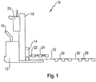
- Fig. 1 shows a schematic view of an automated vehicle 10 that has a load part 14 and a drive part 12.
- the drive part 12 is equipped with a control element 16 which allows manual control of the industrial truck with regard to direction and travel speed.
- Other functional units such as lifting and lowering as well as horns, can also be actuated with the control element 16.
- the drive part 12 also has a drive motor and at least one driven and steered wheel (not shown).
- the load part 14 has a lifting mast 18 on which the vehicle control 20 is attached.
- the vehicle control 20 can, for example, also be equipped with warning lights and have a radio link to a warehouse management system.
- the lifting mast 18 has a load-carrying means 22, which in Fig. 1 is shown in the raised position.
- the load support means 22 can for example have two load forks running parallel to one another.
- the load carrying means 22 is in Fig. 1 shown in a slightly raised position, loaded with a pallet 24 with no load.
- the horizontal block storage which in Fig. 1 is shown, consists for example of the pallets 24, 26 and 28. The same distance 32 is always provided between these pallets. If the block storage shown is set up, for example, the industrial truck 10 sets the pallet 28 down first. The industrial truck then moves its drive back by the distance 30 (opposite to the direction of the arrow) in order to set the pallet 26 here. After driving another distance (against the direction of the arrow), the vehicle is in the position shown and can deposit the pallet 24 here. This creates the horizontal block storage of the pallets 24, 26, 28. In the above method, it goes without saying that the industrial truck can automatically drive through the warehouse, for example after the pallets 26 have been deposited, in order to pick up the pallet 24 at another location , then it returns to the position. The same applies when picking up the pallets.
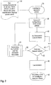
- FIG Fig. 2 The method running in the vehicle control in the industrial truck according to the invention is shown in FIG Fig. 2 shown.
- the method begins with step 34, in which a load delivery starting point is defined.
- the definition takes place via an area or an area in the area from which the loads are based should be placed one behind the other, i.e. along a row.
- This is a horizontal block storage, in which a predetermined distance is provided between the individual stored goods.
- the space in between can serve, for example, to make the individual loads more accessible.
- Method step 36 begins with the load delivery starting point defined in step 34 being reached by the industrial truck.
- a sensor with a configured distance is activated; this corresponds to step 38.
- step 38 the automatic operation for horizontal block storage is initiated in the vehicle control.
- step 40 When activated for the first time with step 38, the vehicle is moved forward a little in a subsequent step 40.
- the signal detection by the personal protection system is active when the truck is traveling.
- a subsequent step 42 it is checked whether the defined distance for the vehicle has been reached. If this is the case, the load is deposited in step 46 and the vehicle returns in step 48 to the load delivery starting point. If the defined distance is not reached directly, the method returns to step 40 via reference 50.
- step 40 there is again limited forward travel.
- the truck scans its way forward with the individual steps.
- an evaluation of the distance data from the distance measuring device takes place in step 44.
- the distance data are evaluated in step 44 either as raw data, ie as distance values, or with regard to the defined protective fields of the personal protection system.
- the distance data 52 obtained in this way form the basis for the query as to whether the desired distance has been reached.
- the desired distance between the load carriers can already be taken into account at the factory when the protection zone is used. An industrial truck is then delivered with protection zones already set accordingly. If, on the other hand, an evaluation of the raw data, that is to say of the recorded distance values, takes place in step 44, the appropriate adjustment can be made after delivery with the aid of a teach-in process. This means that the vehicle with the load picked up is manually positioned once with the desired distance from the previous load for the teach-in process. The distance determined from the raw data is saved, the vehicle then being able to access the saved data in automatic operation and depositing the load at the defined distance.
- the advantage of this variant is that a setting at the factory is not necessary and the customer himself or a customer service technician on behalf of the customer can change and reset the distance as required.
Landscapes
- Engineering & Computer Science (AREA)
- Structural Engineering (AREA)
- Transportation (AREA)
- Life Sciences & Earth Sciences (AREA)
- Geology (AREA)
- Mechanical Engineering (AREA)
- Civil Engineering (AREA)
- Physics & Mathematics (AREA)
- Optics & Photonics (AREA)
- Electromagnetism (AREA)
- Aviation & Aerospace Engineering (AREA)
- Radar, Positioning & Navigation (AREA)
- Remote Sensing (AREA)
- General Physics & Mathematics (AREA)
- Automation & Control Theory (AREA)
- Forklifts And Lifting Vehicles (AREA)
- Control Of Position, Course, Altitude, Or Attitude Of Moving Bodies (AREA)
Abstract
Description
- Die vorliegende Erfindung betrifft ein Flurförderzeug, das eine Fahrzeugsteuerung für einen automatischen Betrieb aufweist.
- Flurförderzeuge, deren Fahrzeugsteuerung für einen automatischen Betrieb geeignet ist, werden zunehmend in der Logistik eingesetzt. Solche Fahrzeuge werden gelegentlich auch als automatisierte Fahrzeuge, Automated Guided Vehicles (AGV) bezeichnet. Je nach Automatisierungsgrad kann hier zwischen teil- und vollautomatisierten Fahrzeugen unterschieden werden. Der unterschiedliche Grad an Automatisierung bezieht sich hierbei insbesondere auf die Aufgaben, die von dem Flurförderzeug automatisch ausgeführt werden können. Automatische Fahrzeuge sind aus Sicherheitsgründen stets mit einem Personenschutzsystem ausgestattet. Das Personenschutzsystem erkennt die Gefahr einer möglichen Kollision mit einer Person oder einem Gegenstand und greift entsprechend in die Steuerung ein, dies kann beispielsweise durch ein Abbremsen des Fahrzeugs und/oder durch ein Ausweichmanöver des Fahrzeugs erfolgen. Personenschutzsysteme besitzen stets eine Abstandsmesseinrichtung, mit der die Umgebung des Fahrzeugs erfasst und Abstände zu Hindernissen und Personen auch während der Fahrt erfasst werden. Um eine einwandfreie Funktionsweise des Personenschutzsystems sicherstellen zu können, werden eine oder mehrere Schutzzonen für die Abstandsmesseinrichtung bzw. das Personenschutzsystem definiert. Die Schutzzone bezeichnet damit einen räumlichen Bereich in der Umgebung des Fahrzeugs, der frei von Hindernissen, Personen und anderen Objekten sein muss, damit ein automatisierter Betrieb, insbesondere eine Fahrt, erfolgen kann.
- Aufgebaut sind derartige Flurförderzeuge, deren Fahrzeugsteuerung für den automatischen Betrieb geeignet ist, dahingehend, dass ein in dem automatischen Betrieb gesteuertes Lasttragmittel und ein in dem automatischen Betrieb gesteuerter Fahrantrieb vorliegen. Selbstverständlich ist es hierbei so, dass für einen nicht automatischen Betrieb die Steuerung über entsprechende Bedienelemente manuell erfolgen kann, auch kann vorgesehen sein, dass ein manueller Eingriff in die Bedienelemente die automatische Steuer überdeckt.
- In der Lagertechnik wird mit dem Begriff der Blocklagerung die Lagerung der Güter ohne Regal oder eine vergleichbare Konstruktion bezeichnet. Bei der Blocklagerung kann zwischen einer horizontalen Lagerung und einer vertikalen Stapelung unterschieden werden, wobei bei der vertikalen Blocklagerung die zu lagernden Güter direkt übereinander gestellt werden. Bei der horizontalen Blocklagerung werden die Güter in einer Ebene nebeneinander abgelegt. Hierbei ist es wünschenswert, dass vorgegebene Abstände zwischen den Gütern bei der horizontalen Blocklagerung eingehalten werden.
- Der Erfindung liegt die Aufgabe zugrunde, eine für den automatischen Betrieb geeignetes Flurförderzeug bereitzustellen, das eine Blocklagerung unterstützen kann.
- Erfindungsgemäß wird die Aufgabe durch ein Flurförderzeug mit den Merkmalen aus Anspruch 1 gelöst. Vorteilhafte Ausgestaltungen bilden die Gegenstände der Unteransprüche.
- Die Erfindung betrifft ein Flurförderzeug, dessen Fahrzeugsteuerung für einen automatischen Betrieb geeignet ist. Das erfindungsgemäße Flurförderzeug weist ein in dem automatischen Betrieb gesteuertes Lasttragmittel, einen in dem automatischen Betrieb gesteuerten Fahrantrieb und ein Personenschutzsystem auf. Das Personenschutzsystem wertet mindestens eine Schutzzone vor dem Lasttragmittel aus, wobei das Personenschutzsystem eine Abstandsmesseinrichtung aufweist, die Abstandsdaten zu Gegenständen und Hindernissen innerhalb der mindestens einen Schutzzone erfasst. Erfindungsgemäß ist vorgesehen, dass die Fahrzeugsteuerung dazu ausgebildet ist, mehrere Ladungsträger in einem vorbestimmten Abstand zueinander abzustellen und/oder aufzunehmen. Dies bedeutet, dass die Fahrzeugsteuerung dazu ausgebildet ist, diesen Ablauf, der daraus besteht, mehrere Ladungsträger abzustellen und/oder aufzunehmen, automatisch durchzuführen. In besonders einfacher Form ist dies möglich, indem zur automatischen Steuerung von Lasttragmittel und Fahrantrieb auf die Abstandsdaten des Personenschutzsystems zurückgegriffen wird. Die Erfindung beruht also auf dem Gedanken, die für die horizontale Blocklagerung erforderlichen Daten nicht durch gesonderte Sensoren zu erfassen, sondern die bereits vorhandene Sensorik mit den Abstandsmessdaten des Personenschutzsystems auch für diese Aufgabe zu nutzen. Wesentlich hierbei ist, dass die Funktion des Personenschutzsystems nicht eingeschränkt wird, sondern ein Rückgriff auf die Abstandsdaten des Personenschutzsystems erfolgen kann, ohne deren Auswertung im Hinblick auf den Personenschutz einzuschränken.
- In einer bevorzugten Ausgestaltung ist das Personenschutzsystem dazu ausgebildet, die von der Abstandsmesseinrichtung erfassten Abstandsdaten für die Fahrzeugsteuerung direkt auszuwerten. Bei dieser Ausgestaltung stellt das Personenschutzsystem also die gewonnenen Abstandsdaten als Rohwerte für die Fahrzeugsteuerung zur Verfügung. Für die horizontale Blocklagerung erweist es sich als vorteilhaft, für die Fahrzeugsteuerung und/oder das Personenschutzsystem eine Teach-In-Funktion vorzusehen, bei der manuell der gewünschte Abstand angefahren und für den automatischen Betrieb gespeichert wird. Die gewonnenen Abstandsdaten werden bei diesem Ansatz zusätzlich im Hinblick auf den Personenschutz ausgewertet und als solche verarbeitet. Durch den Teach-In-Vorgang, bei dem das Flurförderzeug manuell zur gewünschten Bewegung angesteuert wird, können entsprechende Grenzwerte und Schwellwerte für die Parameter und Abstandswerte gesetzt werden, so dass im automatischen Betrieb die Fahrzeugsteuerung das Verfahren aus dem Teach-In-Vorgang wiederholt.
- Bei einem alternativen oder zusätzlichen Ansatz kann vorgesehen sein, dass die Schutzzone oder einzelne Schutzzonen in ihrer Lage und in ihren Abständen so bemessen sind, dass es den gewünschten Abständen für die Ladungsträger entspricht. Bei diesem Ansatz ist es dann nicht länger erforderlich, dass eine zweifache Verarbeitung der Abstandsdaten erfolgt, sondern es wird auch für die Aufgabe der horizontalen Blocklagerung auf die Verarbeitung der Abstandsdaten wie für den Personenschutz zurückgegriffen.
- In einer bevorzugten Weiterbildung ist vorgesehen, den Fahrantrieb für eine automatische Fahrt anzusteuern, bis das Personenschutzsystem und/oder die Fahrzeugsteuerung den vorbestimmten Abstand erkannt hat. Mit dieser Ausgestaltung ist sichergestellt, dass das Fahrzeug von einem ersten Absetz- oder Lagerpunkt automatisch zu dem nächsten Lagerpunkt fahren kann.
- Ist der vorbestimmte Abstand erkannt, liegt also die nächste Lagerposition vor, so dass die nächste Last abgesetzt oder aufgenommen werden kann.
- In einer bevorzugten Ausgestaltung ist als Abstandsmesseinrichtung ein Laserscanner vorgesehen, der zweckmäßigerweise in Richtung der Lasttragmittel orientiert ist.
- In einer weiteren Ausgestaltung der Erfindung können Schutzzonen je nach Aufgabe unterschieden werden. So kann vorgesehen sein, dass eine erste Schutzzone für den Personenschutz, insbesondere für den Personenschutz mit einer vorbestimmten Schutzklasse beispielsweise nach DIN EN 1525 vorgesehen ist. Mindestens eine zweite Schutzzone kann in ihrer Lage und/oder ihren Abmessungen für einen automatisierten Ablage-/Aufnahmevorgang ausgebildet sein. Auf diese Weise können Personenschutz und automatisierter Betrieb durch die Schutzzonen gesteuert werden. Je nach Lage und wechselseitiger Überdeckung der Schutzzonen kann auch vorteilhaft sein, wenn die erste Schutzzone für einen automatisierten Ablage-/Aufnahmevorgang abgeschaltet wird. Das Abschalten der ersten Schutzzone führt nicht zu einem verminderten Personenschutz, denn mit geeigneter Lage der zweiten Schutzzone kann der Personenschutz bereits durch die räumlichen Gegebenheiten verwirklicht sein, auch wenn die zweite Schutzzone für die Steuerung des automatisierten Ablage-/Aufnahmevorgang ausgebildet ist.
- Eine bevorzugte Ausgestaltung der Erfindung wird nachfolgend an einem Ausführungsbeispiel erläutert. Es zeigen:
- Fig. 1
- eine schematische Ansicht eines automatisierten Fahrzeugs mit drei Lastträgern in der Ansicht von der Seite und
- Fig. 2
- ein Flussdiagramm für den in der Fahrzeugsteuerung ablaufenden Vorgang der horizontalen Blocklagerung.
-
Fig. 1 zeigt in einer schematischen Ansicht ein automatisiertes Fahrzeug 10, dass ein Lastteil 14 und ein Antriebsteil 12 aufweist. Das Antriebsteil 12 ist mit einem Steuerorgan 16 ausgestattet, das eine manuelle Steuerung des Flurförderzeugs im Hinblick auf Richtung und Fahrgeschwindigkeit erlaubt. Auch weitere Funktionseinheiten, wie beispielsweise Heben und Senken sowie Hupen, können mit dem Steuerorgan 16 betätigt werden. Das Antriebsteil 12 verfügt zudem über einen Antriebsmotor sowie mindestens ein angetriebenes und gelenktes Rad (nicht dargestellt). - Das Lastteil 14 besitzt in dem dargestellten Ausführungsbeispiel einen Hubmast 18, an dem die Fahrzeugsteuerung 20 angebracht ist. Die Fahrzeugsteuerung 20 kann beispielsweise zusätzlich mit Warnleuchten ausgestattet sein und über eine Funkverbindung zu einem Lagerverwaltungssystem verfügen. Der Hubmast 18 besitzt ein Lasttragmittel 22, das in
Fig. 1 in der angehobenen Position dargestellt ist. Das Lasttragmittel 22 kann beispielsweise zwei parallel zueinander verlaufende Lastgabeln aufweisen. Das Lasttragmittel 22 ist inFig. 1 in einer leicht angehobenen Position dargestellt, mit einer Palette 24 ohne Last beladen. - Die horizontale Blocklagerung, die in
Fig. 1 dargestellt ist, besteht beispielsweise aus den Paletten 24, 26 und 28. Zwischen diesen Paletten ist stets der gleiche Abstand 32 vorgesehen. Wird die dargestellte Blocklagerung beispielsweise aufgebaut, so setzt das Flurförderzeug 10 die Palette 28 zuerst ab. Danach fährt das Flurförderzeug mit seinem Antrieb um die Strecke 30 zurück (entgegen der Pfeilrichtung), um hier die Palette 26 abzusetzen. Nach einer weiteren Fahrt um eine Strecke (entgegen deren Pfeilrichtung) befindet sich das Fahrzeug in der dargestellten Position und kann hier die Palette 24 absetzen. Auf diese Weise entsteht die horizontale Blocklagerung der Paletten 24, 26, 28. Bei dem vorstehenden Verfahren ist es selbstverständlich so, dass das Flurförderzeug beispielsweise nach dem Absetzen der Paletten 26 automatisch durch das Lager fahren kann, um die Palette 24 an einem anderen Ort aufzunehmen, dann kehrt es zu der Position zurück. Gleiches gilt beim Aufnehmen der Paletten. - Das bei dem erfindungsgemäßen Flurförderzeug in der Fahrzeugsteuerung ablaufende Verfahren ist in
Fig. 2 dargestellt. Das Verfahren setzt mit Schritt 34 ein, in dem ein Lastabgabestartpunkt definiert wird. Die Definition erfolgt über eine Fläche bzw. einen Bereich in der Fläche, von dem ausgehend die Lasten hintereinander, also entlang einer Reihe, abgelegt werden sollen. Hierbei handelt es sich um eine horizontale Blocklagerung, bei der ein vorgegebener Abstand zwischen den einzelnen Lagergütern vorgesehen ist. Der Zwischenraum kann hierbei beispielsweise dafür dienen, dass die einzelnen Lasten besser zugänglich sind. - Verfahrensschritt 36 beginnt damit, dass der in Schritt 34 definierte Lastabgabestartpunkt durch das Flurförderzeug erreicht ist. Wenn der Lastabgabestartpunkt erreicht ist, wird ein Sensor mit konfiguriertem Abstand aktiviert, dies entspricht Schritt 38. In Schritt 38 wird in der Fahrzeugsteuerung der automatische Betrieb für die horizontale Blocklagerung eingeleitet.
- Bei einer erstmaligen Aktivierung mit Schritt 38 wird in einem nachfolgenden Schritt 40 das Fahrzeug um ein Stück vorwärts gefahren. Die Signalerfassung durch das Personenschutzsystem ist bei dieser Fahrt des Flurförderzeugs aktiv. In einem nachfolgenden Schritt 42 wird überprüft, ob der definierte Abstand für das Fahrzeug erreicht ist. Ist dies der Fall, so wird in Schritt 46 die Last abgesetzt und das Fahrzeug kehrt in Schritt 48 zu dem Lastabgabestartpunkt zurück. Ist der definierte Abstand nicht direkt erreicht, so kehrt das Verfahren über den Verweis 50 zu Schritt 40 zurück. In Schritt 40 erfolgt wieder eine begrenzte Vorwärtsfahrt. Über die Abfrage 42, ob der definierte Abstand erreicht ist, tastet sich das Flurförderzeug mit den einzelnen Schritten vorwärts. Für die Abfrage 42, ob der definierte Abstand erreicht ist, erfolgt in Schritt 44 eine Auswertung der Abstandsdaten aus dem Abstandmessgerät. Die Abstandsdaten werden in Schritt 44 entweder als Rohdaten, d. h. als Abstandswerte ausgewertet, oder im Hinblick auf die definierten Schutzfelder des Personenschutzsystems. Die so gewonnenen Abstandsdaten 52 liegen der Abfrage, ob der gewünschte Abstand erreicht wurde, zugrunde.
- Im Hinblick auf die beiden Varianten in Schritt 44 zur Auswertung der Abstandsdaten kann bei der Benutzung der Schutzzone der gewünschte Abstand zwischen den Lastträgern bereits werkseitig berücksichtigt werden. Hierbei wird dann ein Flurförderzeug mit bereits entsprechend eingestellten Schutzzonen ausgeliefert. Erfolgt dagegen in Schritt 44 eine Auswertung der Rohdaten, also der erfassten Abstandswerte, so kann nach Auslieferung mit Hilfe eines Teach-In-Vorgangs die entsprechende Anpassung vorgenommen werden. Dies bedeutet, dass das Fahrzeug mit aufgenommener Last für den Teach-In-Vorgang manuell einmalig mit dem gewünschten Abstand zu der vorherigen Last positioniert wird. Die über die Rohdaten ermittelte Entfernung wird gespeichert, wobei dann anschließend das Fahrzeug im automatischen Betrieb auf die gespeicherten Daten zurückgreifen kann und die Last in dem definierten Abstand absetzt. Vorteil dieser Variante ist, dass eine Einstellung werkseitig nicht notwendig ist und der Kunde selbst oder ein Kundendiensttechniker im Auftrag des Kunden den Abstand beliebig verändern und neu einstellen kann.
-
- 10
- Fahrzeug
- 12
- Antrieb steil
- 14
- Lastteil
- 16
- Steuerorgan
- 18
- Hubmast
- 20
- Fahrzeugsteuerung
- 22
- Lasttragmittel
- 24
- Palette
- 26
- Palette
- 28
- Palette
- 30
- Strecke
- 32
- Abstand
- 34
- Verfahrensschritt
- 36
- Verfahrens schritt
- 38
- Verfahrens schritt
- 40
- Verfahrensschritt
- 42
- Verfahrensschritt
- 44
- Verfahrensschritt
- 46
- Verfahrensschritt
- 48
- Verfahrensschritt
- 50
- Verweis
- 52
- Abstandsdaten
Claims (8)
- Flurförderzeug (10), das eine Fahrzeugsteuerung (20) für einen automatischen Betrieb, ein in dem automatischen Betrieb gesteuertes Lasttragmittel (22), einen in dem automatischen Betrieb gesteuerten Fahrantrieb und ein Personenschutzsystem aufweist, das mindestens eine Schutzzone vor dem Lasttragmittel (22) erfasst und für die Fahrzeugsteuerung (20) auswertet, wobei das Personenschutzsystem eine Abstandsmesseinrichtung aufweist, die Abstandsdaten (52) zu Gegenständen und Hindernissen innerhalb der mindestens einen Schutzzone erfasst, dadurch gekennzeichnet, dass die Fahrzeugsteuerung (20) dazu ausgebildet ist, mehrere Ladungsträger in einem vorbestimmten Abstand (32) zueinander abzustellen und/oder aufzunehmen, wobei die Fahrzeugsteuerung (20) zur automatischen Steuerung von Lasttragmittel (22) und Fahrantrieb auf die Abstandsdaten (52) des Personenschutzsystems zurückgreift.
- Flurförderzeug (10) nach Anspruch 1, dadurch gekennzeichnet, dass das Personenschutzsystem dazu ausgebildet ist, die von der Abstandmesseinrichtung gewonnenen Abstandsdaten (52) für die Fahrzeugsteuerung (20) auszuwerten.
- Flurförderzeug (10) nach Anspruch 2, dadurch gekennzeichnet, dass für die Fahrzeugsteuerung (20) und/oder das Personenschutzsystem eine Teach-In-Funktion vorgesehen ist, bei der manuell ein gewünschter Abstand (32) angefahren und für den automatischen Betrieb gespeichert wird.
- Flurförderzeug (10) nach Anspruch 1, dadurch gekennzeichnet, dass das Personenschutzsystem dazu ausgebildet ist, den vorbestimmten Abstand für die Ladungsträger mit Hilfe der mindestens einen Schutzzone zu erkennen.
- Flurförderzeug (10) nach einem der Ansprüche 1 bis 4, dadurch gekennzeichnet, dass der Fahrantrieb für eine automatische Fahrt angesteuert wird, bis das Personenschutzsystem den vorbestimmten Abstand (32) erkannt hat.
- Flurförderzeug (10) nach einem der Ansprüche 1 bis 5, dadurch gekennzeichnet, dass mindestens eine erste Schutzzone für den Personenschutz und mindestens eine zweite Schutzzone für einen automatischen Ablage-/Aufnahmevorgang von Ladungsträgern in einem vorgegebenen Abstand vorgesehen sind.
- Flurförderzeug (10) nach Anspruch 6, dadurch gekennzeichnet, dass die erste Schutzzone für die Dauer des automatisierten Ablage-/Aufnahmevorgangs abgeschaltet ist.
- Flurförderzeug (10) nach einem der Ansprüche 1 bis 7, dadurch gekennzeichnet, dass das Abstandsmessgerät einen Laserscanner aufweist.
Applications Claiming Priority (1)
| Application Number | Priority Date | Filing Date | Title |
|---|---|---|---|
| DE102019115864.8A DE102019115864A1 (de) | 2019-06-11 | 2019-06-11 | Flurförderzeug mit einer Fahrzeugsteuerung für einen automatischen Betrieb |
Publications (2)
| Publication Number | Publication Date |
|---|---|
| EP3750844A1 true EP3750844A1 (de) | 2020-12-16 |
| EP3750844B1 EP3750844B1 (de) | 2021-09-08 |
Family
ID=71083383
Family Applications (1)
| Application Number | Title | Priority Date | Filing Date |
|---|---|---|---|
| EP20178987.2A Active EP3750844B1 (de) | 2019-06-11 | 2020-06-09 | Flurförderzeug mit einer fahrzeugsteuerung für einen automatischen betrieb |
Country Status (3)
| Country | Link |
|---|---|
| US (1) | US20200391987A1 (de) |
| EP (1) | EP3750844B1 (de) |
| DE (1) | DE102019115864A1 (de) |
Families Citing this family (2)
| Publication number | Priority date | Publication date | Assignee | Title |
|---|---|---|---|---|
| US12275606B1 (en) | 2023-12-27 | 2025-04-15 | Niagara Bottling, Llc | Facility layout |
| US12265400B1 (en) | 2023-12-27 | 2025-04-01 | Niagara Bottling, Llc | Facility layout |
Citations (3)
| Publication number | Priority date | Publication date | Assignee | Title |
|---|---|---|---|---|
| EP2339376A1 (de) * | 2009-12-17 | 2011-06-29 | Sick Ag | Optoelektronischer Sensor |
| EP3216743A1 (de) * | 2016-03-07 | 2017-09-13 | STILL GmbH | Flurförderzeug mit assistenzvorrichtung |
| US20190137991A1 (en) * | 2017-11-07 | 2019-05-09 | Stocked Robotics, Inc. | Method and system to retrofit industrial lift trucks for automated material handling in supply chain and logistics operations |
Family Cites Families (6)
| Publication number | Priority date | Publication date | Assignee | Title |
|---|---|---|---|---|
| EP2385014B1 (de) * | 2010-05-03 | 2013-03-27 | Siemens Aktiengesellschaft | Flurförderzeug mit einer Einrichtung zur Identifizierung eines geladenen Transportgutes, und Verfahren zur Identifizierung eines geladenen Transportgutes eines Flurförderzeugs |
| JP5139487B2 (ja) * | 2010-09-03 | 2013-02-06 | 新明工業株式会社 | フォークリフトの安全装置 |
| DE102012200522A1 (de) * | 2012-01-16 | 2013-07-18 | Robert Bosch Gmbh | Abladeassistenzvorrichtung, Flurförderfahrzeug mit einer Abladeassistenzvorrichtung und Verfahren zum Unterstützen des Abladevorgangs einer Ladung |
| JP6469506B2 (ja) * | 2015-04-16 | 2019-02-13 | 株式会社豊田中央研究所 | フォークリフト |
| ES2713683T3 (es) * | 2016-03-18 | 2019-05-23 | Balyo | Vehículo guiado automático |
| JP6451715B2 (ja) * | 2016-10-14 | 2019-01-16 | 株式会社豊田自動織機 | フォークリフト |
-
2019
- 2019-06-11 DE DE102019115864.8A patent/DE102019115864A1/de not_active Withdrawn
-
2020
- 2020-06-09 EP EP20178987.2A patent/EP3750844B1/de active Active
- 2020-06-11 US US16/898,662 patent/US20200391987A1/en not_active Abandoned
Patent Citations (3)
| Publication number | Priority date | Publication date | Assignee | Title |
|---|---|---|---|---|
| EP2339376A1 (de) * | 2009-12-17 | 2011-06-29 | Sick Ag | Optoelektronischer Sensor |
| EP3216743A1 (de) * | 2016-03-07 | 2017-09-13 | STILL GmbH | Flurförderzeug mit assistenzvorrichtung |
| US20190137991A1 (en) * | 2017-11-07 | 2019-05-09 | Stocked Robotics, Inc. | Method and system to retrofit industrial lift trucks for automated material handling in supply chain and logistics operations |
Also Published As
| Publication number | Publication date |
|---|---|
| DE102019115864A1 (de) | 2020-12-17 |
| EP3750844B1 (de) | 2021-09-08 |
| US20200391987A1 (en) | 2020-12-17 |
Similar Documents
| Publication | Publication Date | Title |
|---|---|---|
| EP0800129B1 (de) | Flurförderzeug, das wahlweise manuell oder automatisch betreibbar ausgebildet ist | |
| EP3323770B1 (de) | Verfahren zur bereitstellung der positionen von lagerplätzen in einem lager und flurförderzeug | |
| EP1898290B1 (de) | Flurförderzeugsteuersystem | |
| EP2468678B1 (de) | Flurförderzeug mit einem Sensor zur Erfassung einer räumlichen Umgebung und Verfahren zum Betreiben eines solchen Flurförderzeugs | |
| AT522418B1 (de) | Fertigungsvorrichtung und Fördermittel | |
| EP3118152B1 (de) | Verfahren zur geschwindigkeitssteuerung eines kommissionierflurförderzeugs | |
| EP2339376A1 (de) | Optoelektronischer Sensor | |
| EP3452846B1 (de) | System und verfahren zur bestimmung der position eines transportfahrzeugs sowie transportfahrzeug | |
| EP3333116A1 (de) | Verfahren zur automatischen ausrichtung eines flurförderzeugs in einem warenlager sowie system aus einem flurförderzeug und einem warenlager | |
| EP3750844B1 (de) | Flurförderzeug mit einer fahrzeugsteuerung für einen automatischen betrieb | |
| DE102016104089A1 (de) | Verfahren zur Steuerung eines Flurförderzeugs beim Kommissionieren | |
| EP3960662B1 (de) | System mit einem regalshuttlefahrzeug und einem lagerregal | |
| DE102015113445A1 (de) | Verfahren zur Geschwindigkeitssteuerung eines Kommissionierflurförderzeugs | |
| EP4269321B1 (de) | Fördereinrichtung für ladungsträger | |
| EP3333115B1 (de) | Verfahren zur automatischen ausrichtung eines flurförderzeugs in einem warenlager sowie system aus einem flurförderzeug und einem warenlager | |
| EP3620423B1 (de) | Flurförderzeug mit einer erkennungseinheit | |
| EP3511287B1 (de) | Verfahren zum informationsaustausch zwischen flurförderzeugen und intralogistisches system mit entsprechenden flurförderzeugen | |
| DE102024119287A1 (de) | Frachthandhabungssteuervorrichtung | |
| EP3913455B1 (de) | Steuerung eines fahrzeugs über referenz- sensordaten | |
| DE102019118710A1 (de) | Verfahren und Verladesystem für eine Verladung von Ladungsträgern eines Warenlagers | |
| EP4065453B1 (de) | Fördervorrichtung, bearbeitungsanlage, verfahren zum fördern und/oder bearbeiten von gegenständen | |
| DE102019216178A1 (de) | Vorrichtung an einem fahrerlosen, autonom agierenden Flurförderzeug | |
| EP3984858B1 (de) | Verfahren zum erfassen einer information über die ausbreitung eines warenträgers bei einem zumindest teilweise automatisiert betreibbaren flurförderfahrzeugs | |
| DE102023110320A1 (de) | Verfahren zum Befahren eines Anfahrtswegs eines Flurförderzeugs für eine Aufnahme oder eine Abgabe einer Last | |
| EP4286299A1 (de) | Vorrichtung und verfahren zum kontrollieren einer kontur einer auf einem flurförderzeug aufgenommenen last |
Legal Events
| Date | Code | Title | Description |
|---|---|---|---|
| PUAI | Public reference made under article 153(3) epc to a published international application that has entered the european phase |
Free format text: ORIGINAL CODE: 0009012 |
|
| STAA | Information on the status of an ep patent application or granted ep patent |
Free format text: STATUS: THE APPLICATION HAS BEEN PUBLISHED |
|
| STAA | Information on the status of an ep patent application or granted ep patent |
Free format text: STATUS: REQUEST FOR EXAMINATION WAS MADE |
|
| AK | Designated contracting states |
Kind code of ref document: A1 Designated state(s): AL AT BE BG CH CY CZ DE DK EE ES FI FR GB GR HR HU IE IS IT LI LT LU LV MC MK MT NL NO PL PT RO RS SE SI SK SM TR |
|
| AX | Request for extension of the european patent |
Extension state: BA ME |
|
| 17P | Request for examination filed |
Effective date: 20201118 |
|
| RBV | Designated contracting states (corrected) |
Designated state(s): AL AT BE BG CH CY CZ DE DK EE ES FI FR GB GR HR HU IE IS IT LI LT LU LV MC MK MT NL NO PL PT RO RS SE SI SK SM TR |
|
| RIC1 | Information provided on ipc code assigned before grant |
Ipc: G05D 1/02 20200101ALI20210415BHEP Ipc: B66F 17/00 20060101ALI20210415BHEP Ipc: B66F 9/075 20060101ALI20210415BHEP Ipc: B66F 9/06 20060101AFI20210415BHEP |
|
| GRAP | Despatch of communication of intention to grant a patent |
Free format text: ORIGINAL CODE: EPIDOSNIGR1 |
|
| STAA | Information on the status of an ep patent application or granted ep patent |
Free format text: STATUS: GRANT OF PATENT IS INTENDED |
|
| INTG | Intention to grant announced |
Effective date: 20210615 |
|
| GRAS | Grant fee paid |
Free format text: ORIGINAL CODE: EPIDOSNIGR3 |
|
| GRAA | (expected) grant |
Free format text: ORIGINAL CODE: 0009210 |
|
| STAA | Information on the status of an ep patent application or granted ep patent |
Free format text: STATUS: THE PATENT HAS BEEN GRANTED |
|
| AK | Designated contracting states |
Kind code of ref document: B1 Designated state(s): AL AT BE BG CH CY CZ DE DK EE ES FI FR GB GR HR HU IE IS IT LI LT LU LV MC MK MT NL NO PL PT RO RS SE SI SK SM TR |
|
| REG | Reference to a national code |
Ref country code: GB Ref legal event code: FG4D Free format text: NOT ENGLISH |
|
| REG | Reference to a national code |
Ref country code: CH Ref legal event code: EP Ref country code: AT Ref legal event code: REF Ref document number: 1428435 Country of ref document: AT Kind code of ref document: T Effective date: 20210915 |
|
| REG | Reference to a national code |
Ref country code: DE Ref legal event code: R096 Ref document number: 502020000176 Country of ref document: DE |
|
| REG | Reference to a national code |
Ref country code: IE Ref legal event code: FG4D Free format text: LANGUAGE OF EP DOCUMENT: GERMAN |
|
| REG | Reference to a national code |
Ref country code: SE Ref legal event code: TRGR |
|
| REG | Reference to a national code |
Ref country code: LT Ref legal event code: MG9D |
|
| REG | Reference to a national code |
Ref country code: NL Ref legal event code: MP Effective date: 20210908 |
|
| PG25 | Lapsed in a contracting state [announced via postgrant information from national office to epo] |
Ref country code: RS Free format text: LAPSE BECAUSE OF FAILURE TO SUBMIT A TRANSLATION OF THE DESCRIPTION OR TO PAY THE FEE WITHIN THE PRESCRIBED TIME-LIMIT Effective date: 20210908 Ref country code: ES Free format text: LAPSE BECAUSE OF FAILURE TO SUBMIT A TRANSLATION OF THE DESCRIPTION OR TO PAY THE FEE WITHIN THE PRESCRIBED TIME-LIMIT Effective date: 20210908 Ref country code: NO Free format text: LAPSE BECAUSE OF FAILURE TO SUBMIT A TRANSLATION OF THE DESCRIPTION OR TO PAY THE FEE WITHIN THE PRESCRIBED TIME-LIMIT Effective date: 20211208 Ref country code: HR Free format text: LAPSE BECAUSE OF FAILURE TO SUBMIT A TRANSLATION OF THE DESCRIPTION OR TO PAY THE FEE WITHIN THE PRESCRIBED TIME-LIMIT Effective date: 20210908 Ref country code: FI Free format text: LAPSE BECAUSE OF FAILURE TO SUBMIT A TRANSLATION OF THE DESCRIPTION OR TO PAY THE FEE WITHIN THE PRESCRIBED TIME-LIMIT Effective date: 20210908 Ref country code: BG Free format text: LAPSE BECAUSE OF FAILURE TO SUBMIT A TRANSLATION OF THE DESCRIPTION OR TO PAY THE FEE WITHIN THE PRESCRIBED TIME-LIMIT Effective date: 20211208 Ref country code: LT Free format text: LAPSE BECAUSE OF FAILURE TO SUBMIT A TRANSLATION OF THE DESCRIPTION OR TO PAY THE FEE WITHIN THE PRESCRIBED TIME-LIMIT Effective date: 20210908 |
|
| PG25 | Lapsed in a contracting state [announced via postgrant information from national office to epo] |
Ref country code: LV Free format text: LAPSE BECAUSE OF FAILURE TO SUBMIT A TRANSLATION OF THE DESCRIPTION OR TO PAY THE FEE WITHIN THE PRESCRIBED TIME-LIMIT Effective date: 20210908 Ref country code: GR Free format text: LAPSE BECAUSE OF FAILURE TO SUBMIT A TRANSLATION OF THE DESCRIPTION OR TO PAY THE FEE WITHIN THE PRESCRIBED TIME-LIMIT Effective date: 20211209 |
|
| PG25 | Lapsed in a contracting state [announced via postgrant information from national office to epo] |
Ref country code: IS Free format text: LAPSE BECAUSE OF FAILURE TO SUBMIT A TRANSLATION OF THE DESCRIPTION OR TO PAY THE FEE WITHIN THE PRESCRIBED TIME-LIMIT Effective date: 20220108 Ref country code: SM Free format text: LAPSE BECAUSE OF FAILURE TO SUBMIT A TRANSLATION OF THE DESCRIPTION OR TO PAY THE FEE WITHIN THE PRESCRIBED TIME-LIMIT Effective date: 20210908 Ref country code: SK Free format text: LAPSE BECAUSE OF FAILURE TO SUBMIT A TRANSLATION OF THE DESCRIPTION OR TO PAY THE FEE WITHIN THE PRESCRIBED TIME-LIMIT Effective date: 20210908 Ref country code: RO Free format text: LAPSE BECAUSE OF FAILURE TO SUBMIT A TRANSLATION OF THE DESCRIPTION OR TO PAY THE FEE WITHIN THE PRESCRIBED TIME-LIMIT Effective date: 20210908 Ref country code: PT Free format text: LAPSE BECAUSE OF FAILURE TO SUBMIT A TRANSLATION OF THE DESCRIPTION OR TO PAY THE FEE WITHIN THE PRESCRIBED TIME-LIMIT Effective date: 20220110 Ref country code: PL Free format text: LAPSE BECAUSE OF FAILURE TO SUBMIT A TRANSLATION OF THE DESCRIPTION OR TO PAY THE FEE WITHIN THE PRESCRIBED TIME-LIMIT Effective date: 20210908 Ref country code: NL Free format text: LAPSE BECAUSE OF FAILURE TO SUBMIT A TRANSLATION OF THE DESCRIPTION OR TO PAY THE FEE WITHIN THE PRESCRIBED TIME-LIMIT Effective date: 20210908 Ref country code: EE Free format text: LAPSE BECAUSE OF FAILURE TO SUBMIT A TRANSLATION OF THE DESCRIPTION OR TO PAY THE FEE WITHIN THE PRESCRIBED TIME-LIMIT Effective date: 20210908 Ref country code: CZ Free format text: LAPSE BECAUSE OF FAILURE TO SUBMIT A TRANSLATION OF THE DESCRIPTION OR TO PAY THE FEE WITHIN THE PRESCRIBED TIME-LIMIT Effective date: 20210908 Ref country code: AL Free format text: LAPSE BECAUSE OF FAILURE TO SUBMIT A TRANSLATION OF THE DESCRIPTION OR TO PAY THE FEE WITHIN THE PRESCRIBED TIME-LIMIT Effective date: 20210908 |
|
| REG | Reference to a national code |
Ref country code: DE Ref legal event code: R097 Ref document number: 502020000176 Country of ref document: DE |
|
| PLBE | No opposition filed within time limit |
Free format text: ORIGINAL CODE: 0009261 |
|
| STAA | Information on the status of an ep patent application or granted ep patent |
Free format text: STATUS: NO OPPOSITION FILED WITHIN TIME LIMIT |
|
| PG25 | Lapsed in a contracting state [announced via postgrant information from national office to epo] |
Ref country code: DK Free format text: LAPSE BECAUSE OF FAILURE TO SUBMIT A TRANSLATION OF THE DESCRIPTION OR TO PAY THE FEE WITHIN THE PRESCRIBED TIME-LIMIT Effective date: 20210908 |
|
| 26N | No opposition filed |
Effective date: 20220609 |
|
| PG25 | Lapsed in a contracting state [announced via postgrant information from national office to epo] |
Ref country code: MC Free format text: LAPSE BECAUSE OF FAILURE TO SUBMIT A TRANSLATION OF THE DESCRIPTION OR TO PAY THE FEE WITHIN THE PRESCRIBED TIME-LIMIT Effective date: 20210908 Ref country code: IT Free format text: LAPSE BECAUSE OF FAILURE TO SUBMIT A TRANSLATION OF THE DESCRIPTION OR TO PAY THE FEE WITHIN THE PRESCRIBED TIME-LIMIT Effective date: 20210908 |
|
| REG | Reference to a national code |
Ref country code: BE Ref legal event code: MM Effective date: 20220630 |
|
| PG25 | Lapsed in a contracting state [announced via postgrant information from national office to epo] |
Ref country code: LU Free format text: LAPSE BECAUSE OF NON-PAYMENT OF DUE FEES Effective date: 20220609 Ref country code: IE Free format text: LAPSE BECAUSE OF NON-PAYMENT OF DUE FEES Effective date: 20220609 |
|
| PG25 | Lapsed in a contracting state [announced via postgrant information from national office to epo] |
Ref country code: BE Free format text: LAPSE BECAUSE OF NON-PAYMENT OF DUE FEES Effective date: 20220630 |
|
| P01 | Opt-out of the competence of the unified patent court (upc) registered |
Effective date: 20230628 |
|
| REG | Reference to a national code |
Ref country code: CH Ref legal event code: PL |
|
| PG25 | Lapsed in a contracting state [announced via postgrant information from national office to epo] |
Ref country code: MK Free format text: LAPSE BECAUSE OF FAILURE TO SUBMIT A TRANSLATION OF THE DESCRIPTION OR TO PAY THE FEE WITHIN THE PRESCRIBED TIME-LIMIT Effective date: 20210908 Ref country code: CY Free format text: LAPSE BECAUSE OF FAILURE TO SUBMIT A TRANSLATION OF THE DESCRIPTION OR TO PAY THE FEE WITHIN THE PRESCRIBED TIME-LIMIT Effective date: 20210908 Ref country code: CH Free format text: LAPSE BECAUSE OF NON-PAYMENT OF DUE FEES Effective date: 20230630 |
|
| PG25 | Lapsed in a contracting state [announced via postgrant information from national office to epo] |
Ref country code: HU Free format text: LAPSE BECAUSE OF FAILURE TO SUBMIT A TRANSLATION OF THE DESCRIPTION OR TO PAY THE FEE WITHIN THE PRESCRIBED TIME-LIMIT; INVALID AB INITIO Effective date: 20200609 |
|
| PG25 | Lapsed in a contracting state [announced via postgrant information from national office to epo] |
Ref country code: MT Free format text: LAPSE BECAUSE OF FAILURE TO SUBMIT A TRANSLATION OF THE DESCRIPTION OR TO PAY THE FEE WITHIN THE PRESCRIBED TIME-LIMIT Effective date: 20210908 |
|
| GBPC | Gb: european patent ceased through non-payment of renewal fee |
Effective date: 20240609 |
|
| PG25 | Lapsed in a contracting state [announced via postgrant information from national office to epo] |
Ref country code: GB Free format text: LAPSE BECAUSE OF NON-PAYMENT OF DUE FEES Effective date: 20240609 |
|
| PGFP | Annual fee paid to national office [announced via postgrant information from national office to epo] |
Ref country code: AT Payment date: 20250721 Year of fee payment: 5 |
|
| PGFP | Annual fee paid to national office [announced via postgrant information from national office to epo] |
Ref country code: SE Payment date: 20250618 Year of fee payment: 6 |
|
| PG25 | Lapsed in a contracting state [announced via postgrant information from national office to epo] |
Ref country code: TR Free format text: LAPSE BECAUSE OF FAILURE TO SUBMIT A TRANSLATION OF THE DESCRIPTION OR TO PAY THE FEE WITHIN THE PRESCRIBED TIME-LIMIT Effective date: 20210908 |
|
| PG25 | Lapsed in a contracting state [announced via postgrant information from national office to epo] |
Ref country code: SI Free format text: LAPSE BECAUSE OF FAILURE TO SUBMIT A TRANSLATION OF THE DESCRIPTION OR TO PAY THE FEE WITHIN THE PRESCRIBED TIME-LIMIT Effective date: 20210908 |
|
| PG25 | Lapsed in a contracting state [announced via postgrant information from national office to epo] |
Ref country code: CH Free format text: THE PATENT HAS BEEN ANNULLED BY A DECISION OF A NATIONAL AUTHORITY Effective date: 20230630 |
|
| PGFP | Annual fee paid to national office [announced via postgrant information from national office to epo] |
Ref country code: DE Payment date: 20260623 Year of fee payment: 7 |
|
| PGFP | Annual fee paid to national office [announced via postgrant information from national office to epo] |
Ref country code: FR Payment date: 20260622 Year of fee payment: 7 |
|
| PG25 | Lapsed in a contracting state [announced via postgrant information from national office to epo] |
Ref country code: AT Free format text: LAPSE BECAUSE OF NON-PAYMENT OF DUE FEES Effective date: 20250609 |