EP3750774A1 - Centering device for centering a front coupler of a railway car and method for centering a front coupler of a railway car - Google Patents
Centering device for centering a front coupler of a railway car and method for centering a front coupler of a railway car Download PDFInfo
- Publication number
- EP3750774A1 EP3750774A1 EP20179820.4A EP20179820A EP3750774A1 EP 3750774 A1 EP3750774 A1 EP 3750774A1 EP 20179820 A EP20179820 A EP 20179820A EP 3750774 A1 EP3750774 A1 EP 3750774A1
- Authority
- EP
- European Patent Office
- Prior art keywords
- centering
- coupling rod
- cam disk
- spring
- coupler
- Prior art date
- Legal status (The legal status is an assumption and is not a legal conclusion. Google has not performed a legal analysis and makes no representation as to the accuracy of the status listed.)
- Withdrawn
Links
Images





Classifications
-
- B—PERFORMING OPERATIONS; TRANSPORTING
- B61—RAILWAYS
- B61G—COUPLINGS; DRAUGHT AND BUFFING APPLIANCES
- B61G7/00—Details or accessories
- B61G7/10—Mounting of the couplings on the vehicle
- B61G7/12—Adjustable coupling bars, e.g. for centralisation purposes
Definitions
- the present invention concerns a centering device for centering a front coupler of a railway car of a railway vehicle, and a method for centering such front coupler.
- the present invention also relates to a railway vehicle comprising a centering device for centering a front coupler of a railway car of a railway vehicle.
- the present invention relates in particular to a centering device which can be easily deactivated for coupling respective couplers of railway cars in tight curves, or for easy accessibility of components mounted near the front automatic coupler.
- a coupler of a railway car comprises in a manner per se known a coupling rod which is, at a rear end, connected to a main joint and which, at a front free end, includes coupling members for connection with analogous coupling members placed on another coupler road of another railway car.
- the coupler is laterally swingable and a centering device is arranged to secure the coupling rod in a non-swingable neutral position when the coupler is inactive.
- Couplers of the above-related kind are found on pulled railroad cars as well as pulling locomotives, and have frequently the form of automatic couplers, i.e. couplers that enable automatic connection without manual handling of the proper coupling members.
- automatic couplers are centrally placed on the individual end of a car body or chassis, and are swingable in order to enable connection of railway cars that are placed in curves, i.e. on railway tracks that are more or less curved.
- the front couplers should be swingable for the railway vehicle to be able to alternatingly pass righthand curves as well as left-hand curves.
- an individual coupler is inactive, i.e.
- a neutral position which usually consists of an intermediate position in which the coupler points perpendicularly out from the end of the car body, because otherwise the coupler would dangle during ride.
- auxiliary support is usually required, at least for long couplers having a large dead weight that counteracts and compensates the vertical stresses.
- the coupling rods of the couplers are swingable not only laterally, but to a certain extent also vertically in order to enable ride in hilly topography.
- Front automatic couplers have a specific gathering range, based on type of coupler head selected, which is a range in which two couplers can couple automatically.
- a coupler is free to rotate horizontally without resistance but if there is a curve such that the couplers are not within gathering range, then automatic coupling is not possible, so, in order to rescue a railway vehicle, it is necessary to manually align the couplers and then perform the coupling.
- Prior art centering devices provide resistance to manual movement for coupling.
- couplers usually have spring actuated centering devices it is not possible to keep a coupler at specific angle because the centering device pushes the coupler to make it center.
- This known device have the disadvantages of being bulky and not allowing isolating the centering function of the device for keeping the coupler at specific angle, thus leading to great life cycle costs and difficulties in maintenance and operation of the centering device.
- a front coupler is shown, preferably in the form of an automatic coupler, which in a conventional way includes a coupling rod 1, which at a front, free end includes coupling members 2,3 and at a rear end is connected to a main joint generally designated 4.
- a vertical axle or axle spindle 5 is included, which at upper and lower ends is connected to a fastening plate 6, which can be fixed on an car body (not shown), e. g., by means of a screw or bolt joint indicated 7.
- the fastening plate 6 is placed in the middle of the end of the car body in question, with the plate on a vertical plane from which the coupling rod 1 protrudes substantially horizontally.
- the main joint 4 includes a ring 8 surrounding the axle 5, which ring is turnable backward and forward in relation to the axle and to which the coupling rod 1 is connected.
- the main joint 4 enables lateral swinging of the coupling rod 1, e.g. at a 45° angle of deflection to each direction from the position shown in fig. 1 .
- the main joint 4 includes means, not shown, to enable turning of the coupling rod 1 as well as limited vertical swinging of the coupling rod in relation to the fastening plate 6.
- the coupling rod 1 in figure 1 is shown in a neutral or starting position, in which the coupling rod 1 points straight ahead, i.e., perpendicularly to the fastening plate 6. From this neutral position, the coupling rod 1 may be variably swung towards the left as well as the right to a maximum angle of deflection.
- Characteristic of the front coupler according to the prior art is that there is a bracket-like carrier 9 placed under the coupling rod 1, which is connected to a turnable ring included in a house 10 arranged under the main joint 4, in which a device for centering the front coupler, of known type, is integrated or built-in.
- an innovative device for centering the front automatic coupler, to be placed into the house 10 is provided, and it will be disclosed in detail the following .
- Figure 2 shows a prospective view of a device 50 for centering a front coupler of a railway car (also called in the following "centering device” ) according to the present invention, said centering device 50 being arranged to be placed into the house 10 for securing the coupling rod 1 in the neutral position thereof, according to the disclosure of WO 2005/032906 .
- Figure 3 shows an exploded view of the centering device 50.
- the centering device 50 has the purpose of securing the coupling rod 1 in the neutral position thereof.
- the centering device 50 comprises a cam disk 52 and a roller device 54 arranged to engage a grove 52a of the cam disk 52 (see figure 6 ).
- the coupling rod 1 is swung out laterally to an angle of deflection that is determined by the curve radius of the track, so that coupling members of the respective coupler can be brought into engagement with each other.
- Figure 4 shows a side view of the centering device 50 placed under the coupling rod 1
- figure 5 shows a side sectional view of an enlargement of the centering device 50 of figure 4 .
- the cam disk 52 is connected to the coupling rod 1, so that when it rotates, the coupling rod 1 rotates as well.
- roller device 54 is fixed to an end 56 of a screw-thread component 58 by means of a screw 60.
- the screw-thread component 58 comprises a proximal plate 62a and a distal plate 62b arranged to be placed in contact with the respective ends of a spring 64, preferably made of Belleville washers, which is placed between the plates 62a, 62b, wound around a cylindrical support 66.
- the plates 62a, 62b can be identical each other or different each other in shape.
- the plates 62a, 62b are circular-shaped, square-shaped or triangle-shaped.
- the plates 62a, 62b can have however any other desired shape.
- a cylinder 68 is advantageously provided around the spring 64 to protect it.
- Bars 70 connect the two plates 62a, 62b and fix them at the end of the spring 64 so that the cylindrical support 66 protrudes out from the distal plate 62b.
- plates 62a, 62b are triangle-shaped as visible on Figure 3
- three bars 70 connect the two plates 62a, 62b.
- Figure 6 shows a sectional top view of the device of figure 2 in an engaged position wherein the roller device 54 engages the grove 52a of the cam disk 52.
- a nut 72 is screwed on the cylindrical support 66 so that when the nut 72 is tightened, it compresses the spring 64 and the roller device 54 retracts out of the grove 52a of the cam disk 52, as visible on figure 7 .
- Figure 7 shows a sectional top view of the centering device 50 in a retracted position wherein the nut 72 has been tightened, so as to compress the spring 64 and the roller device 54 has retracted out of the groove 52a.
- cam disk 52 Since now the roller device 54 is out of grove 52a, the cam disk 52 is free to rotate. Once the nut 72 is released, the roller device 54 touches the cam disk 52 and performs the centering function of the automatic coupler. Since the cam disk 52 is connected to the coupling rod 1, rotation of cam disk 52 controls the rotation of the front coupler.
- the profile of the cam disk 52 can be made to suit any centering angle requirement.
- the centering device 50 for centering a front automatic coupler of the present invention has the following advantages:
- Figure 8 shows a railway vehicle 100 having a coupling rod 1 and a centering device 50 as above disclosed.
Landscapes
- Engineering & Computer Science (AREA)
- Mechanical Engineering (AREA)
- Braking Arrangements (AREA)
Abstract
- a cam disk (52) having a lateral surface with a recess (52a), said cam disk (52) being connected to the coupling rod (1) so that when it rotates, the coupling rod (1) rotates;
- a roller device (54) arranged to contact the lateral surface of the cam disk (52) when it is pushed by a spring (64) towards said lateral surface of the cam disk (52), so that when the cam disk (52) rotates, the roller device (54) engages the recess (52a) thus limiting pivoting of the cam disk (52) and centering the coupling rod (1), said roller device (54) being further arranged to disengage the recess (52a) when the spring (64) is compressed by tightening a nut (72), so as to make the coupling rod (1) free to rotate.
Description
- The present invention concerns a centering device for centering a front coupler of a railway car of a railway vehicle, and a method for centering such front coupler.
- The present invention also relates to a railway vehicle comprising a centering device for centering a front coupler of a railway car of a railway vehicle.
- The present invention relates in particular to a centering device which can be easily deactivated for coupling respective couplers of railway cars in tight curves, or for easy accessibility of components mounted near the front automatic coupler.
- A coupler of a railway car comprises in a manner per se known a coupling rod which is, at a rear end, connected to a main joint and which, at a front free end, includes coupling members for connection with analogous coupling members placed on another coupler road of another railway car. The coupler is laterally swingable and a centering device is arranged to secure the coupling rod in a non-swingable neutral position when the coupler is inactive.
- Couplers of the above-related kind are found on pulled railroad cars as well as pulling locomotives, and have frequently the form of automatic couplers, i.e. couplers that enable automatic connection without manual handling of the proper coupling members. In practice, such automatic couplers are centrally placed on the individual end of a car body or chassis, and are swingable in order to enable connection of railway cars that are placed in curves, i.e. on railway tracks that are more or less curved. During ride, the front couplers should be swingable for the railway vehicle to be able to alternatingly pass righthand curves as well as left-hand curves. However, when an individual coupler is inactive, i.e. not connected to the coupler of another railway car, the same has to be reliably retained in a neutral position, which usually consists of an intermediate position in which the coupler points perpendicularly out from the end of the car body, because otherwise the coupler would dangle during ride.
- Furthermore, automatic couplers are subjected to constant as well as occasional vertical loads of considerable size, namely in the form of the dead weight of the coupler.
- For these reasons, some form of auxiliary support is usually required, at least for long couplers having a large dead weight that counteracts and compensates the vertical stresses. In this connection, it should also be mentioned that the coupling rods of the couplers are swingable not only laterally, but to a certain extent also vertically in order to enable ride in hilly topography.
- Front automatic couplers have a specific gathering range, based on type of coupler head selected, which is a range in which two couplers can couple automatically. A coupler is free to rotate horizontally without resistance but if there is a curve such that the couplers are not within gathering range, then automatic coupling is not possible, so, in order to rescue a railway vehicle, it is necessary to manually align the couplers and then perform the coupling. Prior art centering devices provide resistance to manual movement for coupling.
- Since the couplers usually have spring actuated centering devices it is not possible to keep a coupler at specific angle because the centering device pushes the coupler to make it center.
- Prior art devices for centering a front coupler are known, for example from document
WO 2005/032906 (Dellner). - This known device have the disadvantages of being bulky and not allowing isolating the centering function of the device for keeping the coupler at specific angle, thus leading to great life cycle costs and difficulties in maintenance and operation of the centering device.
- There is therefore the need to provide an innovative device and method for centering a front coupler of a railway car capable of isolating the centering function of the coupler, with a reliable design and a better functionality, lower life-cycle costs and which is easy to maintain.
- These and other objects are fully achieved by virtue of device for centering a front coupler of a railway car having the characteristics defined in independent claim 1, by a method for centering a front coupler of a railway car having the characteristics defined in independent claim 7, and by a railway vehicle as defined in
claim 9. - Preferred embodiments of the invention are specified in the dependent claims, whose subject-matter is to be understood as forming an integral part of the present description.
- Further characteristics and advantages of the present invention will become apparent from the following description, provided merely by way of a non-limiting example, with reference to the enclosed drawings, in which:
-
Figure 1 is a perspective view of a front automatic coupler of a railway car of the prior art shown in its entirety; -
Figure 2 shows a prospective view of a device for centering a front automatic coupler of a railway car according to the present invention; -
Figure 3 shows an exploded view of the device offigure 2 ; -
Figure 4 shows a side view of the device for centering a front automatic coupler according to the present invention, -
Figure 5 shows a side sectional view of an enlargement of the device for centering a front automatic coupler offigure 5 ; -
Figure 6 shows a sectional top view of the device for centering a front automatic coupler in an engaged position; -Figure 7 shows a sectional top view of the device offigure 2 in a retracted position; and -
Figure 8 shows a railway vehicle comprising a device for centering a front automatic coupler of a railway car according to the present invention. - In
figure 1 , which is derived fromfigure 1 of documentWO 2005/032906 , a front coupler is shown, preferably in the form of an automatic coupler, which in a conventional way includes a coupling rod 1, which at a front, free end includescoupling members axle spindle 5 is included, which at upper and lower ends is connected to afastening plate 6, which can be fixed on an car body (not shown), e. g., by means of a screw or bolt joint indicated 7. - In practice, the
fastening plate 6 is placed in the middle of the end of the car body in question, with the plate on a vertical plane from which the coupling rod 1 protrudes substantially horizontally. Furthermore, themain joint 4 includes aring 8 surrounding theaxle 5, which ring is turnable backward and forward in relation to the axle and to which the coupling rod 1 is connected. In other words, themain joint 4 enables lateral swinging of the coupling rod 1, e.g. at a 45° angle of deflection to each direction from the position shown infig. 1 . Furthermore, themain joint 4 includes means, not shown, to enable turning of the coupling rod 1 as well as limited vertical swinging of the coupling rod in relation to thefastening plate 6. - In view of the above, it is clear that the coupling rod 1 in
figure 1 is shown in a neutral or starting position, in which the coupling rod 1 points straight ahead, i.e., perpendicularly to thefastening plate 6. From this neutral position, the coupling rod 1 may be variably swung towards the left as well as the right to a maximum angle of deflection. - Characteristic of the front coupler according to the prior art is that there is a bracket-
like carrier 9 placed under the coupling rod 1, which is connected to a turnable ring included in ahouse 10 arranged under themain joint 4, in which a device for centering the front coupler, of known type, is integrated or built-in. - According to the present invention, an innovative device for centering the front automatic coupler, to be placed into the
house 10, is provided, and it will be disclosed in detail the following . -
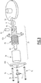
Figure 2 shows a prospective view of adevice 50 for centering a front coupler of a railway car (also called in the following "centering device") according to the present invention, said centeringdevice 50 being arranged to be placed into thehouse 10 for securing the coupling rod 1 in the neutral position thereof, according to the disclosure ofWO 2005/032906 . -
Figure 3 shows an exploded view of thecentering device 50. - The
centering device 50 has the purpose of securing the coupling rod 1 in the neutral position thereof. - The
centering device 50 comprises acam disk 52 and aroller device 54 arranged to engage a grove 52a of the cam disk 52 (seefigure 6 ). - When the coupling rod 1 is in the neutral position, it points straight ahead, and the
roller device 54 is in engagement with the grove 52a, as it is shown infig. 6 . Thanks to the centeringdevice 50, ride may take place without the coupling rod 1 swinging or dangling in an uncontrolled way. - When the front coupler has to be connected to an analogous front coupler on another railway car, and the two railway cars are placed on a non-straight track, the coupling rod 1 is swung out laterally to an angle of deflection that is determined by the curve radius of the track, so that coupling members of the respective coupler can be brought into engagement with each other.
- The above-cited swinging out takes place against the action of a
spring 64 of thecentering device 50, as described in detail here below. -
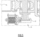
Figure 4 shows a side view of thecentering device 50 placed under the coupling rod 1, andfigure 5 shows a side sectional view of an enlargement of thecentering device 50 offigure 4 . - In
figure 5 , thecam disk 52 is in an engaged position corresponding to the one offigure 6 , disclosed in detail herein-below. - The
cam disk 52 is connected to the coupling rod 1, so that when it rotates, the coupling rod 1 rotates as well. - Returning to
figure 3 , theroller device 54 is fixed to anend 56 of a screw-thread component 58 by means of ascrew 60. - The screw-
thread component 58 comprises aproximal plate 62a and adistal plate 62b arranged to be placed in contact with the respective ends of aspring 64, preferably made of Belleville washers, which is placed between theplates cylindrical support 66. Theplates plates plates - A
cylinder 68 is advantageously provided around thespring 64 to protect it. -
Bars 70 connect the twoplates spring 64 so that thecylindrical support 66 protrudes out from thedistal plate 62b. For example, whenplates Figure 3 , threebars 70 connect the twoplates -
Figure 6 shows a sectional top view of the device offigure 2 in an engaged position wherein theroller device 54 engages the grove 52a of thecam disk 52. - A
nut 72 is screwed on thecylindrical support 66 so that when thenut 72 is tightened, it compresses thespring 64 and theroller device 54 retracts out of the grove 52a of thecam disk 52, as visible onfigure 7 . - When the
nut 72 is unscrewed, as visible onfigure 6 , thespring 64 push theroller device 54 against the lateral surface of thecam disk 52 so that, when thecam disk 52 rotates, theroller device 54 engages the grove 52a thus centering the coupling rod 1. -
Figure 7 shows a sectional top view of thecentering device 50 in a retracted position wherein thenut 72 has been tightened, so as to compress thespring 64 and theroller device 54 has retracted out of thegroove 52a. - Since now the
roller device 54 is out of grove 52a, thecam disk 52 is free to rotate. Once thenut 72 is released, theroller device 54 touches thecam disk 52 and performs the centering function of the automatic coupler. Since thecam disk 52 is connected to the coupling rod 1, rotation ofcam disk 52 controls the rotation of the front coupler. - The profile of the
cam disk 52 can be made to suit any centering angle requirement. - The centering
device 50 for centering a front automatic coupler of the present invention has the following advantages: - it allows to easily isolate the centering function without the need to use any special tool because the coupler can be easily moved away for good accessibility, thus reducing the maintenance time;
- it gives to maintenance operators the flexibility to move the automatic coupler laterally without any effort, for maintenance activities of the coupler or of its surrounding equipment;
- it allows to keep the coupler at a specified desired angle for coupling in tight curves;
- it improves the reliability of the coupler and decreases the life cycle cost as it is not active when couplers are coupled during service operation; and
- it has a simple design.
-
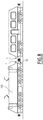
Figure 8 shows arailway vehicle 100 having a coupling rod 1 and a centeringdevice 50 as above disclosed. - Clearly, the principle of the invention remaining the same, the embodiments and the details of production can be varied considerably from what has been described and illustrated purely by way of non-limiting example, without departing from the scope of protection of the present invention as defined by the attached claims.
Claims (10)
- Centering device (50) for centering a front coupler of a railway car comprising a coupling rod (1), said centering device (50) comprising:- a cam disk (52) having a lateral surface with a recess (52a), said cam disk (52) being connected to the coupling rod (1) so that when it rotates, the coupling rod (1) rotates;- a roller device (54) arranged to contact the lateral surface of the cam disk (52) when it is pushed by a spring (64) towards said lateral surface of the cam disk (52), so that when the cam disk (52) rotates, the roller device (54) engages the recess (52a) thus limiting pivoting of the cam disk (52) and centering the coupling rod (1), said roller device (54) being further arranged to disengage the recess (52a) when the spring (64) is compressed by tightening a nut (72), so as to make the coupling rod (1) free to rotate.
- The centering device (50) of claim 1, wherein the spring (64) and the roller device (54) are mounted on a screw-thread component (58).
- The centering device (50) of claims 1 or 2, wherein the spring (64) is made of Belleville washers.
- The centering device (50) of claim 2 or 3, wherein the screw-thread component (58) comprises a proximal plate (62a) and a distal plate (62b) arranged to be put in contact with the respective ends of the spring (64).
- The centering device (50) of claim 4, wherein the spring (64) is wound around a cylindrical support (66) which protrudes out from the distal plate (62b) and wherein the nut (72) is screwed on said cylindrical support (66).
- The centering device (50) of claim 5, wherein a cylinder (68) is provided around the spring (64) to protect it.
- Method for centering a front coupler of a railway car comprising a coupling rod (1), the method comprising the steps of:- providing a centering device (50) according to any of the preceding claims;- releasing the nut (72) so that the roller device (54) touches the cam disk (52) and engages the recess (52a), thus centering the coupling rod (1).
- Method according to claim 7, further comprising the step of tightening the nut (72) to compress the spring (64) so that the roller device (54) retracts out of the recess (52a) of the cam disk (52), thus making the coupling rod (1) free to rotate.
- Railway vehicle (100) comprising a centering device (50) for centering a front coupler according to any of the claims 1 to 6.
- Railway vehicle (100) according to claim 9, wherein the centering device (50) is coupled to a coupling rod (1), thus allowing centering the coupling rod (1) by releasing the nut (72) so that the roller device (54) touches the cam disk (52) and engages the recess (52a)
Applications Claiming Priority (1)
| Application Number | Priority Date | Filing Date | Title |
|---|---|---|---|
| IN201941023369 | 2019-06-12 |
Publications (1)
| Publication Number | Publication Date |
|---|---|
| EP3750774A1 true EP3750774A1 (en) | 2020-12-16 |
Family
ID=71094232
Family Applications (1)
| Application Number | Title | Priority Date | Filing Date |
|---|---|---|---|
| EP20179820.4A Withdrawn EP3750774A1 (en) | 2019-06-12 | 2020-06-12 | Centering device for centering a front coupler of a railway car and method for centering a front coupler of a railway car |
Country Status (1)
| Country | Link |
|---|---|
| EP (1) | EP3750774A1 (en) |
Cited By (2)
| Publication number | Priority date | Publication date | Assignee | Title |
|---|---|---|---|---|
| WO2022245268A1 (en) * | 2021-05-20 | 2022-11-24 | Dellner Couplers Ab | Coupler with angular position detection assembly, angular position detection system and method |
| WO2023070806A1 (en) * | 2021-10-29 | 2023-05-04 | 青岛思锐科技有限公司 | Centering apparatus |
Citations (4)
| Publication number | Priority date | Publication date | Assignee | Title |
|---|---|---|---|---|
| US4569455A (en) * | 1984-04-04 | 1986-02-11 | Harvey Hubbell Incorporated | Centering detent |
| WO2005032906A1 (en) | 2003-10-03 | 2005-04-14 | Dellner Couplers Ab | A vehicle coupler |
| CN201792867U (en) * | 2010-06-29 | 2011-04-13 | 南车戚墅堰机车车辆工艺研究所有限公司 | Tight-lock coupler hanging device |
| CN109278787A (en) * | 2018-08-29 | 2019-01-29 | 中车戚墅堰机车车辆工艺研究所有限公司 | Centering support mechanism, coupler buffer device adopting centering support mechanism and centering method |
-
2020
- 2020-06-12 EP EP20179820.4A patent/EP3750774A1/en not_active Withdrawn
Patent Citations (4)
| Publication number | Priority date | Publication date | Assignee | Title |
|---|---|---|---|---|
| US4569455A (en) * | 1984-04-04 | 1986-02-11 | Harvey Hubbell Incorporated | Centering detent |
| WO2005032906A1 (en) | 2003-10-03 | 2005-04-14 | Dellner Couplers Ab | A vehicle coupler |
| CN201792867U (en) * | 2010-06-29 | 2011-04-13 | 南车戚墅堰机车车辆工艺研究所有限公司 | Tight-lock coupler hanging device |
| CN109278787A (en) * | 2018-08-29 | 2019-01-29 | 中车戚墅堰机车车辆工艺研究所有限公司 | Centering support mechanism, coupler buffer device adopting centering support mechanism and centering method |
Cited By (3)
| Publication number | Priority date | Publication date | Assignee | Title |
|---|---|---|---|---|
| WO2022245268A1 (en) * | 2021-05-20 | 2022-11-24 | Dellner Couplers Ab | Coupler with angular position detection assembly, angular position detection system and method |
| WO2023070806A1 (en) * | 2021-10-29 | 2023-05-04 | 青岛思锐科技有限公司 | Centering apparatus |
| KR20240049370A (en) * | 2021-10-29 | 2024-04-16 | 씨알알씨 브레이킹 시스템 컴퍼니 리미티드 | centering device |
Similar Documents
| Publication | Publication Date | Title |
|---|---|---|
| AU2014215585B2 (en) | Rail loading and unloading machine | |
| EP1770047B2 (en) | Device for hanging a rail, especially a transporting rail of a conveyor or a hoist | |
| EA024012B1 (en) | IMPROVED INTERMODAL RAILWAY VEHICLE FOR FORMING A TRAIN | |
| US11629699B2 (en) | Apparatuses for wind turbine blade railroad transportation and related systems and methods | |
| US11698054B2 (en) | Apparatuses for wind turbine blade railroad transportation and related systems and methods | |
| CN102421967A (en) | Rail loaded trains for transporting steel rails | |
| US11795915B2 (en) | Apparatuses for wind turbine blade railroad transportation and related systems and methods | |
| EP0081576A1 (en) | Bidirectionally operative tie exchanging apparatus | |
| US5775714A (en) | Tow bar | |
| US4556200A (en) | Re-railing jack | |
| EP1667886B1 (en) | A vehicle coupler | |
| EP3929059B1 (en) | Conveyor carriage | |
| CN109927745A (en) | A kind of hitch connection equipment and its application method for drawing fault car | |
| CN104590985A (en) | Railway vehicle integral lifting device and method | |
| CN222875994U (en) | A stable installation outer wheel stopper for rail vehicles | |
| CN114687259A (en) | Alignment mechanism for rail working device and rail working device | |
| CN204231938U (en) | A kind of grain header and safe grain barrel-removing thereof | |
| US4991727A (en) | Drawhead alignment device | |
| CN111762223B (en) | Automatic release pull rod mechanism | |
| CN204279481U (en) | A kind of anti-drop device | |
| CN217170691U (en) | Cart stop device for port machinery maintenance | |
| WO2020069855A1 (en) | Mobile buffer for railway vehicle | |
| CN109549708B (en) | Medical trolley | |
| CN108860207B (en) | Upper-acting type car coupler anti-jump safety system and application method thereof | |
| RU2392138C2 (en) | Device to replace absorption apparatus |
Legal Events
| Date | Code | Title | Description |
|---|---|---|---|
| PUAI | Public reference made under article 153(3) epc to a published international application that has entered the european phase |
Free format text: ORIGINAL CODE: 0009012 |
|
| STAA | Information on the status of an ep patent application or granted ep patent |
Free format text: STATUS: THE APPLICATION HAS BEEN PUBLISHED |
|
| AK | Designated contracting states |
Kind code of ref document: A1 Designated state(s): AL AT BE BG CH CY CZ DE DK EE ES FI FR GB GR HR HU IE IS IT LI LT LU LV MC MK MT NL NO PL PT RO RS SE SI SK SM TR |
|
| AX | Request for extension of the european patent |
Extension state: BA ME |
|
| STAA | Information on the status of an ep patent application or granted ep patent |
Free format text: STATUS: REQUEST FOR EXAMINATION WAS MADE |
|
| 17P | Request for examination filed |
Effective date: 20201211 |
|
| RBV | Designated contracting states (corrected) |
Designated state(s): AL AT BE BG CH CY CZ DE DK EE ES FI FR GB GR HR HU IE IS IT LI LT LU LV MC MK MT NL NO PL PT RO RS SE SI SK SM TR |
|
| GRAP | Despatch of communication of intention to grant a patent |
Free format text: ORIGINAL CODE: EPIDOSNIGR1 |
|
| STAA | Information on the status of an ep patent application or granted ep patent |
Free format text: STATUS: GRANT OF PATENT IS INTENDED |
|
| INTG | Intention to grant announced |
Effective date: 20210817 |
|
| GRAJ | Information related to disapproval of communication of intention to grant by the applicant or resumption of examination proceedings by the epo deleted |
Free format text: ORIGINAL CODE: EPIDOSDIGR1 |
|
| STAA | Information on the status of an ep patent application or granted ep patent |
Free format text: STATUS: REQUEST FOR EXAMINATION WAS MADE |
|
| INTC | Intention to grant announced (deleted) | ||
| GRAP | Despatch of communication of intention to grant a patent |
Free format text: ORIGINAL CODE: EPIDOSNIGR1 |
|
| STAA | Information on the status of an ep patent application or granted ep patent |
Free format text: STATUS: GRANT OF PATENT IS INTENDED |
|
| INTG | Intention to grant announced |
Effective date: 20220202 |
|
| STAA | Information on the status of an ep patent application or granted ep patent |
Free format text: STATUS: THE APPLICATION IS DEEMED TO BE WITHDRAWN |
|
| 18D | Application deemed to be withdrawn |
Effective date: 20220614 |