EP3750773A1 - Railway car and railway coupling mounting assembly thereof - Google Patents
Railway car and railway coupling mounting assembly thereof Download PDFInfo
- Publication number
- EP3750773A1 EP3750773A1 EP18923873.6A EP18923873A EP3750773A1 EP 3750773 A1 EP3750773 A1 EP 3750773A1 EP 18923873 A EP18923873 A EP 18923873A EP 3750773 A1 EP3750773 A1 EP 3750773A1
- Authority
- EP
- European Patent Office
- Prior art keywords
- coupler
- mounting
- seat
- limiting block
- mounting assembly
- Prior art date
- Legal status (The legal status is an assumption and is not a legal conclusion. Google has not performed a legal analysis and makes no representation as to the accuracy of the status listed.)
- Granted
Links
Images


Classifications
-
- B—PERFORMING OPERATIONS; TRANSPORTING
- B61—RAILWAYS
- B61G—COUPLINGS; DRAUGHT AND BUFFING APPLIANCES
- B61G3/00—Couplings comprising mating parts of similar shape or form which can be coupled without the use of any additional element or elements
- B61G3/02—Couplings comprising mating parts of similar shape or form which can be coupled without the use of any additional element or elements with interengaging movably-mounted hooks or links guided into alignment by a gathering device, e.g. "Dowty" type
-
- B—PERFORMING OPERATIONS; TRANSPORTING
- B61—RAILWAYS
- B61G—COUPLINGS; DRAUGHT AND BUFFING APPLIANCES
- B61G7/00—Details or accessories
- B61G7/10—Mounting of the couplings on the vehicle
-
- B—PERFORMING OPERATIONS; TRANSPORTING
- B61—RAILWAYS
- B61G—COUPLINGS; DRAUGHT AND BUFFING APPLIANCES
- B61G7/00—Details or accessories
Definitions
- the present application relates to the technical field of rail vehicle, and in particular to a rail vehicle and a coupler mounting assembly thereof.
- a screw coupler mounting seat is provided on a lower cover of a coupler box. Threaded blind holes are provided according to positions of screw coupler mounting bolts on the screw coupler mounting seat, and the position of a screw coupler stop seat is designed according to the threaded blind holes.
- the screw coupler stop seat and the mounting seat form a screw coupler mounting structure.
- the above screw coupler mounting structure can bear a certain compressive load, which is achieved by shearing of the screw coupler mounting bolts.
- the vehicle traction device would bear the compressive load of 300KN, but the screw coupler and the mounting structure based on UIC standard cannot bear the compressive load of 300KN. If the traction device of the vehicle is subjected to a large impact compressive load in the rescue condition, it is very likely that the mounting bolts will shear off, which will result in the failure of vehicle rescue and may cause irreversible damage to the coupler box and other parts of the vehicle body.
- An object of the present application is to provide a rail vehicle and a coupler mounting assembly thereof, which can effectively avoid coupler failure caused by the shear fracture of the mounting bolts.
- a coupler mounting assembly applied to rail vehicles which includes a coupler box body for placing a coupler, and further includes:
- the position-limiting block includes:
- the stop block includes a horizontal plate located above the vertical plate and provided along the length direction of the coupler box body, wherein the horizontal plate is longer than the vertical plate; an end face provided on a side wall of a rear end of the horizontal plate for abutting against the locking end; a bent end provided at a front end of the horizontal plate and extending downward to abut against the notch; and via holes penetrating through upper and lower surfaces of the horizontal plate for connecting the position-limiting block with the stop block by mounting bolts, wherein a hole diameter of each via hole is larger than a hole diameter of each mounting hole, so that the stop block is movable within a certain range relative to the position-limiting block.
- fitting surfaces of the locking end and the end surface are first wedge surfaces cooperating with each other, and fitting surfaces of the notch and the bent end are second wedge surfaces cooperating with each other.
- first wedge surfaces and the second wedge surfaces are both steel surfaces, and both the first wedge surfaces and the second wedge surfaces are inclined from top to bottom towards the front end, and the inclination angle ranges from 6 degrees to 14 degrees.
- At least two mounting bolts are provided along the length direction of the position-limiting block, and an interlocking gasket clamped under the heads of the mounting bolts for connecting all the mounting bolts is further provided on the upper surface of the stop block.
- the mounting seat is connected to the coupler body support plate by a vertically arranged fastening bolt, and the fastening bolt is lower than the mounting bolt in the vertical direction.
- the coupler mounting assembly further includes a joist mounting seat for installing a joist or a tight-lock coupler mounting seat, wherein the joist is for fixing the screw coupler, and the tight-lock coupler mounting seat is for fixing the tight-lock coupler.
- the joist mounting seat is provided with multiple sets of fixing holes along the vertical direction for adjusting the height of the joist or the tight-lock coupler mounting seat.
- the joist mounting seat is specifically two mounting frames arranged along the vertical direction, and the two mounting frames are arranged in parallel.
- a rail vehicle is further provided according to the present application, which includes the coupler mounting assembly according to any one of the above aspects.
- the coupler mounting assembly for rail vehicles limits the movement of the coupler body support plate toward the forward direction of the rail vehicle by means of the stop seat located at the front end of the coupler body support plate, and limits the movement of the coupler body support plate toward the backward direction of the rail vehicle by means of the stop block located at the rear end of the coupler body support plate.
- the stop block is movable relative to the position-limiting block, and the relative movement is along the length direction of the coupler box body and is within a certain range. That is, after the relative movement of the stop block and the position-limiting block reaches the limit, the coupler body support plate cannot further move, thereby limiting the coupler body support plate to a certain range.
- the bolt is free from the axial impact by the coupler body support plate, and the reliability of the overall structure is improved.
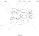
- Figure 1 is an axonometric view of a coupler mounting assembly provided with a screw coupler according to an embodiment of the present application
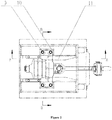
- Figure 2 is a bottom view of Figure 1
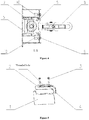
- Figure 3 is a sectional view taken along a direction A-A in Figure 2
- Figure 4 is a sectional view taken along a direction B-B in Figure 2
- Figure 5 is a schematic structural view of the wedge-shaped position-limiting block and wedge-shaped stop block of Figure 1 during installation
- Figure 6 is a schematic view of Figure 1 viewed from another angle
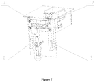
- Figure 7 is a schematic structural view of a tight-lock coupler mounting seat according to an embodiment of the present application during installation.
- the front end refers to the right end and the rear end refers to the left end;
- the longitudinal direction refers to the travel direction of the rail vehicle, and the lateral direction refers to the direction perpendicular to the longitudinal direction in the horizontal plane.
- a coupler mounting assembly applied to rail vehicles is provided according to the present application, which includes a coupler box body.
- the coupler box body is for placing a coupler.
- a mounting seat 10 is provided on two sides of the coupler box body.
- a stop seat 11 is fixedly provided on two sides of the coupler box body.
- the stop seat 11 can be regarded as a part of the coupler box body.
- the stop seat 11 extends along the length direction of the coupler box body, and is located at a front end of the mounting seat 10.
- a coupler body support plate 5 is provided on the mounting seat 10, and the stop seat 11 is configured to restrict the coupler body support plate 5 from moving in the forward direction of the vehicle.
- the stop seat 11 is further a component that transmits the tensile force of the vehicle.
- the mounting seat 10 and the stop seat 11 form a basic mounting structure of screw coupler, as shown in Figures 1 to 4 .
- Two position-limiting blocks 1 can be respectively welded to two sides of the coupler box body, and the two position-limiting blocks 1 both extend along the length direction of the coupler box body, and the position-limiting blocks 1 are located at a rear end of the mounting seat 10.
- a stop block 2 is slidably connected with the position-limiting block 1 and abuts against the coupler body support plate 5.
- the stop block 2 is movable within a certain range relative to the position-limiting block 1 along the length direction of the coupler box body, and the stop block 2 and the stop seat 11 are respectively located at a rear end and a front end of the coupler body support plate 5. That is, the position-limiting block 1 can cooperate with the stop block 2 to restrict the movement of the coupler body support plate 5 toward the rear end.
- the position-limiting block 1 is further an important component for transmitting compressive load.
- the position-limiting block 1 and the stop seat 11 are located on a same longitudinal straight line.
- the coupler body support plate 5 is hindered from moving toward the front or rear end, which can alleviate the impact on the coupler body support plate 5 to a certain extent during the rescue process and improve the reliability of the rail vehicle structure.
- the position-limiting block 1 includes a vertical plate, a locking end and a notch.
- the position-limiting block 1 may be integrally formed.
- the vertical plate is arranged along the length direction of the coupler box body.
- the locking end is provided on an upper surface of the left end (that is, the rear end) of the vertical plate and extends upward.
- the notch is provided on a side wall of the right end (that is, the front end) of the vertical plate and extends downward.
- Mounting holes are provided on the upper surface of the vertical plate and located between the locking end and the notch.
- the stop block 2 may be integrally formed and includes a horizontal plate.
- the horizontal plate is located above the vertical plate and extends along the length direction of the coupler box body, and the horizontal plate is longer than the vertical plate.
- An end face is provided on a side wall of the rear end (that is, the left end) of the horizontal plate, and can abut against the right side of the locking end.
- a bent end is provided at the front end (that is, the right end) of the horizontal plate and extends downward, and the left side of the bent end abuts against the right side of the notch.
- via holes are provided in the horizontal plate and penetrates through upper and lower surfaces of the horizontal plate.
- Mounting bolts 3 pass through the via holes of the stop block 2 from top to bottom, and are fastened in the mounting holes of the position-limiting block 1, thereby connecting the stop block 2 with the position-limiting block 1.
- a hole diameter of each via hole is larger than a hole diameter of each mounting hole, so that the stop block 2 is movable within a certain range relative to the position-limiting block 1.
- the stop block 2 can be regarded as a movable part, which is movable relative to the position-limiting block 1 along the length direction of the coupler box body.
- the through hole of the stop block 2 may be an oblong hole, and the adjustable direction of the oblong hole is the length direction of the vehicle.
- fitting surfaces of the locking end and the end surface are first wedge surfaces cooperating with each other, and fitting surfaces of the notch and the bent end are second wedge surfaces cooperating with each other, as shown in Figure 5 .
- the first wedge surfaces and the second wedge surfaces are both steel surfaces, and both the first wedge surfaces and the second wedge surfaces are inclined from top to bottom towards the front end, and the inclination angle ranges from 6 degrees to 14 degrees.
- both the stop block 2 and the position-limiting block 1 are designed according to the principle of friction self-locking.
- Both the stop block 2 and the position-limiting block 1 are provided with two friction self-locking inclined planes.
- the angle of the inclined plane can be selected from 6 degrees to 14 degrees. If the angle is too large, the longitudinal adjustable amount of the stop block 2 is relatively large and the stop block 2 is easy to disassemble, but the friction self-locking effect is not good.
- the angle of the inclined surface in the practical engineering application of the present application is 11 degrees to 12 degrees.
- the mounting seat 10 is connected to the coupler body support plate 5 by a vertically arranged fastening bolt 9, and the fastening bolt 9 is lower than the mounting bolt 3 in the vertical direction.
- this specific embodiment also relates to the working principle of interlocking gaskets.
- the interlocking gasket 4 is provided to interlock the at least two mounting bolts 3, thereby further improving the reliability of the vehicle body structure.
- the mounting seat 10, the stop seat 11, the position-limiting block 1 and other bent parts are welded together to form the coupler box.
- the coupler support plate 5 (including drawbar and elastic device) is fastened on the mounting seat 10 with four fastening bolts 9. During the installation, it is ensured that the front end face of the coupler support plate 5 is in close contact with the stop seat 11. Then, the two groups of inclined planes of the stop block 2 and the position-limiting block 1 are adjusted to fit well, then the interlocking gasket 4 and an anti-loosening gasket are installed, and then the stop block 2 is fastened with the mounting bolts 3.
- the mounting bolts 3 that fasten the stop block 2 are unscrewed at first, then an auxiliary tool (with threads) is screwed into a threaded hole in the middle of the stop block 2 (as shown in Figure 5 ), then a vertical pulling force is applied thereon after the auxiliary tool is tightened, then the stop block 2 is pulled out, and then the fastening bolts 9 are loosened, completing the disassembly process.
- structures of the end traction beam of the current rail vehicle used for shunting are singular, one structure is the screw coupler mounting structure, and another is the tight-lock coupler mounting structure, but the two are not well integrated. Once the coupler draft gear or other parts fail, the rescue work of vehicles will be impossible.
- the coupler mounting assembly further includes a joist mounting seat 6 for installing a joist 7 or a tight-lock coupler mounting seat 13, wherein the joist 7 is for fixing a screw coupler 8, and the tight-lock coupler mounting seat 13 is for fixing a tight-lock coupler.
- the screw coupler cannot be used, for example, the screw coupler is damaged in the rescue process of the vehicle or the vehicle travels under some special conditions, the screw coupler body and the joist 7 can be removed, then the tight-lock coupler mounting seat 13 is installed on the joist mounting seat 6, then the tight-lock coupler is installed and the height of the tight-lock coupler from the rail surface is adjusted to complete the vehicle coupling work.
- the joist mounting seat 6 is provided with multiple sets of fixing holes along the vertical direction for adjusting the height of the joist 7 or the tight-lock coupler mounting seat 13, as shown in Figures 6 and 7 .
- the joist mounting seat 6 is two mounting frames arranged along the vertical direction, and the two mounting frames are arranged in parallel.
- the assembly in the vehicle rescue process, the assembly can bear larger impact compressive load, and the reliability of the vehicle structure is improved.
- the problem that the screw coupler and the tight-lock coupler cannot be compatibly installed in the whole vehicle design is solved.
- the installation conversion of the screw coupler and the tight-lock coupler is convenient, which meets the requirements of modular design of the vehicle body.
- the joist mounting seat can be installed to serve as both a screw coupler body joist and a height-adjustable tight-lock coupler, thereby expanding the functional diversity of the end traction beam.
- the self-locking structure is simple, does not occupy too much space of the coupler box, and is beneficial to the design and arrangement of draft gears.
- a rail vehicle is further provided according to the present application, which includes the coupler mounting assembly according to the above embodiments. Reference may be made to the conventional technology for other parts of the rail vehicle, which will not be described herein.
Landscapes
- Engineering & Computer Science (AREA)
- Mechanical Engineering (AREA)
- Connection Of Plates (AREA)
- Body Structure For Vehicles (AREA)
- Seats For Vehicles (AREA)
Abstract
Description
- The present application claims the priority to Chinese Patent Application No.
201810669841.X - The present application relates to the technical field of rail vehicle, and in particular to a rail vehicle and a coupler mounting assembly thereof.
- In the current rail vehicle technology, according to relevant standards, most rail vehicles are provided with coupler mounting devices. A screw coupler mounting seat is provided on a lower cover of a coupler box. Threaded blind holes are provided according to positions of screw coupler mounting bolts on the screw coupler mounting seat, and the position of a screw coupler stop seat is designed according to the threaded blind holes. The screw coupler stop seat and the mounting seat form a screw coupler mounting structure. The above screw coupler mounting structure can bear a certain compressive load, which is achieved by shearing of the screw coupler mounting bolts.
- According to the standard of BS EN 15020-2006+A1-2010 "Performance Requirements, Special Joint Geometric Dimensions and Test Methods of Railway Facilities-Rescue Couplers", in the case of rescuing a faulty vehicle, the vehicle traction device would bear the compressive load of 300KN, but the screw coupler and the mounting structure based on UIC standard cannot bear the compressive load of 300KN. If the traction device of the vehicle is subjected to a large impact compressive load in the rescue condition, it is very likely that the mounting bolts will shear off, which will result in the failure of vehicle rescue and may cause irreversible damage to the coupler box and other parts of the vehicle body.
- An object of the present application is to provide a rail vehicle and a coupler mounting assembly thereof, which can effectively avoid coupler failure caused by the shear fracture of the mounting bolts.
- In order to achieve the above object, a coupler mounting assembly applied to rail vehicles is provided according to the present application, which includes a coupler box body for placing a coupler, and further includes:
- a mounting seat provided on two sides of the coupler box body;
- a stop seat fixed on two sides of the coupler box body and extending along a length direction of the coupler box body, wherein the stop seat is located at a front end of the mounting seat;
- a coupler body support plate mounted to the mounting seat and abutting against the stop seat to limit movement of the coupler toward a forward direction of the rail vehicle;
- a position-limiting block fixed on two sides of the coupler box body and extending along the length direction of the coupler box body, wherein the position-limiting block is located at a rear end of the mounting seat; and
- a stop block which is slidably connected with the position-limiting block and abuts against the coupler body support plate, wherein the stop block is movable within a certain range relative to the position-limiting block along the length direction of the coupler box body, and the stop block and the stop seat are respectively located at a rear end and a front end of the coupler body support plate.
- Preferably, the position-limiting block includes:
- a vertical plate provided along the length direction of the coupler box body;
- a locking end provided on an upper surface of the vertical plate, located at a rear end of the position-limiting block and extending upward;
- a notch provided on a front side wall of the vertical plate and extending downward; and
- mounting holes provided on the upper surface of the vertical plate and located between the locking end and the notch.
- The stop block includes a horizontal plate located above the vertical plate and provided along the length direction of the coupler box body, wherein the horizontal plate is longer than the vertical plate;
an end face provided on a side wall of a rear end of the horizontal plate for abutting against the locking end;
a bent end provided at a front end of the horizontal plate and extending downward to abut against the notch; and
via holes penetrating through upper and lower surfaces of the horizontal plate for connecting the position-limiting block with the stop block by mounting bolts, wherein a hole diameter of each via hole is larger than a hole diameter of each mounting hole, so that the stop block is movable within a certain range relative to the position-limiting block. - Preferably, fitting surfaces of the locking end and the end surface are first wedge surfaces cooperating with each other, and fitting surfaces of the notch and the bent end are second wedge surfaces cooperating with each other.
- Preferably, the first wedge surfaces and the second wedge surfaces are both steel surfaces, and both the first wedge surfaces and the second wedge surfaces are inclined from top to bottom towards the front end, and the inclination angle ranges from 6 degrees to 14 degrees.
- Preferably, at least two mounting bolts are provided along the length direction of the position-limiting block, and an interlocking gasket clamped under the heads of the mounting bolts for connecting all the mounting bolts is further provided on the upper surface of the stop block.
- Preferably, the mounting seat is connected to the coupler body support plate by a vertically arranged fastening bolt, and the fastening bolt is lower than the mounting bolt in the vertical direction.
- Preferably, the coupler mounting assembly further includes a joist mounting seat for installing a joist or a tight-lock coupler mounting seat, wherein the joist is for fixing the screw coupler, and the tight-lock coupler mounting seat is for fixing the tight-lock coupler.
- Preferably, the joist mounting seat is provided with multiple sets of fixing holes along the vertical direction for adjusting the height of the joist or the tight-lock coupler mounting seat.
- Preferably, the joist mounting seat is specifically two mounting frames arranged along the vertical direction, and the two mounting frames are arranged in parallel.
- A rail vehicle is further provided according to the present application, which includes the coupler mounting assembly according to any one of the above aspects.
- Compared with the above background technology, the coupler mounting assembly for rail vehicles provided by the present application limits the movement of the coupler body support plate toward the forward direction of the rail vehicle by means of the stop seat located at the front end of the coupler body support plate, and limits the movement of the coupler body support plate toward the backward direction of the rail vehicle by means of the stop block located at the rear end of the coupler body support plate. The stop block is movable relative to the position-limiting block, and the relative movement is along the length direction of the coupler box body and is within a certain range. That is, after the relative movement of the stop block and the position-limiting block reaches the limit, the coupler body support plate cannot further move, thereby limiting the coupler body support plate to a certain range. Meanwhile, based on the above structure, the bolt is free from the axial impact by the coupler body support plate, and the reliability of the overall structure is improved.
- For more clearly illustrating embodiments of the present application or the technical solutions in the conventional technology, drawings for describing the embodiments or the conventional technology will be briefly described hereinafter. Apparently, the drawings in the following description are only examples of the present application, and for those skilled in the art, other drawings may be obtained based on the provided drawings without any creative efforts.
-
Figure 1 is an axonometric view of a coupler mounting assembly provided with a screw coupler according to an embodiment of the present application; -
Figure 2 is a bottom view ofFigure 1 ; -
Figure 3 is a sectional view taken along a direction A-A inFigure 2 ; -
Figure 4 is a sectional view taken along a direction B-B inFigure 2 ; -
Figure 5 is a schematic structural view of a wedge-shaped position-limiting block and a wedge-shaped stop block ofFigure 1 during installation; -
Figure 6 is a schematic view ofFigure 1 viewed from another angle; and -
Figure 7 is a schematic structural view of a tight-lock coupler mounting seat according to an embodiment of the present application during installation. - The technical solutions according to the embodiments of the present application will be described clearly and completely as follows in conjunction with the drawings in the embodiments of the present application. It is apparent that the described embodiments are only a part of the embodiments according to the present application, rather than all of the embodiments. Based on the embodiments in the present application, all of other embodiments, made by the person skilled in the art without any creative efforts, fall into the scope of the present application.
- In order to provide the person skilled in the art with a better understanding of the solution of the present application, the present application is described hereinafter in further detail in conjunction with the drawings and embodiments.
- Referring to
Figures 1 to 7 ,Figure 1 is an axonometric view of a coupler mounting assembly provided with a screw coupler according to an embodiment of the present application;Figure 2 is a bottom view ofFigure 1 ;Figure 3 is a sectional view taken along a direction A-A inFigure 2 ;Figure 4 is a sectional view taken along a direction B-B inFigure 2 ;Figure 5 is a schematic structural view of the wedge-shaped position-limiting block and wedge-shaped stop block ofFigure 1 during installation;Figure 6 is a schematic view ofFigure 1 viewed from another angle; andFigure 7 is a schematic structural view of a tight-lock coupler mounting seat according to an embodiment of the present application during installation. - In this specification, taking
Figure 1 as an example, the front end refers to the right end and the rear end refers to the left end; the longitudinal direction refers to the travel direction of the rail vehicle, and the lateral direction refers to the direction perpendicular to the longitudinal direction in the horizontal plane. - A coupler mounting assembly applied to rail vehicles is provided according to the present application, which includes a coupler box body. The coupler box body is for placing a coupler. A
mounting seat 10 is provided on two sides of the coupler box body. Astop seat 11 is fixedly provided on two sides of the coupler box body. Thestop seat 11 can be regarded as a part of the coupler box body. Thestop seat 11 extends along the length direction of the coupler box body, and is located at a front end of themounting seat 10. A couplerbody support plate 5 is provided on themounting seat 10, and thestop seat 11 is configured to restrict the couplerbody support plate 5 from moving in the forward direction of the vehicle. Besides, thestop seat 11 is further a component that transmits the tensile force of the vehicle. The mountingseat 10 and thestop seat 11 form a basic mounting structure of screw coupler, as shown inFigures 1 to 4 . - Two position-limiting
blocks 1 can be respectively welded to two sides of the coupler box body, and the two position-limitingblocks 1 both extend along the length direction of the coupler box body, and the position-limitingblocks 1 are located at a rear end of the mountingseat 10. Astop block 2 is slidably connected with the position-limitingblock 1 and abuts against the couplerbody support plate 5. Thestop block 2 is movable within a certain range relative to the position-limitingblock 1 along the length direction of the coupler box body, and thestop block 2 and thestop seat 11 are respectively located at a rear end and a front end of the couplerbody support plate 5. That is, the position-limitingblock 1 can cooperate with thestop block 2 to restrict the movement of the couplerbody support plate 5 toward the rear end. Besides, the position-limitingblock 1 is further an important component for transmitting compressive load. The position-limitingblock 1 and thestop seat 11 are located on a same longitudinal straight line. - With this arrangement, based on that the
stop block 2 is movable within a certain range along the length direction of the coupler box body relative to the position-limitingblock 1, and because of thestop seat 11 fixed on the coupler box body, the couplerbody support plate 5 is hindered from moving toward the front or rear end, which can alleviate the impact on the couplerbody support plate 5 to a certain extent during the rescue process and improve the reliability of the rail vehicle structure. - Regarding the specific arrangement of the position-limiting
block 1 and thestop block 2, as shown inFigures 3 to 5 , the position-limitingblock 1 includes a vertical plate, a locking end and a notch. The position-limitingblock 1 may be integrally formed. Referring toFigure 5 , the vertical plate is arranged along the length direction of the coupler box body. The locking end is provided on an upper surface of the left end (that is, the rear end) of the vertical plate and extends upward. The notch is provided on a side wall of the right end (that is, the front end) of the vertical plate and extends downward. Mounting holes are provided on the upper surface of the vertical plate and located between the locking end and the notch. - The
stop block 2 may be integrally formed and includes a horizontal plate. The horizontal plate is located above the vertical plate and extends along the length direction of the coupler box body, and the horizontal plate is longer than the vertical plate. An end face is provided on a side wall of the rear end (that is, the left end) of the horizontal plate, and can abut against the right side of the locking end. A bent end is provided at the front end (that is, the right end) of the horizontal plate and extends downward, and the left side of the bent end abuts against the right side of the notch. Besides, via holes are provided in the horizontal plate and penetrates through upper and lower surfaces of the horizontal plate. Mountingbolts 3 pass through the via holes of thestop block 2 from top to bottom, and are fastened in the mounting holes of the position-limitingblock 1, thereby connecting thestop block 2 with the position-limitingblock 1. Moreover, a hole diameter of each via hole is larger than a hole diameter of each mounting hole, so that thestop block 2 is movable within a certain range relative to the position-limitingblock 1. In other words, thestop block 2 can be regarded as a movable part, which is movable relative to the position-limitingblock 1 along the length direction of the coupler box body. The through hole of thestop block 2 may be an oblong hole, and the adjustable direction of the oblong hole is the length direction of the vehicle. - More specifically, fitting surfaces of the locking end and the end surface are first wedge surfaces cooperating with each other, and fitting surfaces of the notch and the bent end are second wedge surfaces cooperating with each other, as shown in
Figure 5 . The first wedge surfaces and the second wedge surfaces are both steel surfaces, and both the first wedge surfaces and the second wedge surfaces are inclined from top to bottom towards the front end, and the inclination angle ranges from 6 degrees to 14 degrees. - As shown in
Figure 3 , when the coupler body such as the screw coupler is subjected to an impact compressive load F, in order to restrict the couplerbody support plate 5 from moving backward, structures of thestop block 2 and the position-limitingblock 1 are designed according to the principle of friction self-locking. Both thestop block 2 and the position-limitingblock 1 are provided with two friction self-locking inclined planes. Considering that the dynamic friction factor between the two steel bodies is generally 0.1 to 0.25, the angle of the inclined plane can be selected from 6 degrees to 14 degrees. If the angle is too large, the longitudinal adjustable amount of thestop block 2 is relatively large and thestop block 2 is easy to disassemble, but the friction self-locking effect is not good. If the angle is too small, the friction self-locking effect is good, but the longitudinal adjustable amount of thestop block 2 is greatly reduced, and a larger vertical pulling force is required to disassemble thestop block 2, which is not conductive to the disassembly of the screw coupler. Considering that thestop block 2 has been fastened by two vertical mountingbolts 3, in order to increase the longitudinal adjustable amount of thestop block 2 and facilitate the disassembly of the screw coupler, the angle of the inclined surface in the practical engineering application of the present application is 11 degrees to 12 degrees. Even if the screw coupler is subjected to a large impact compressive load (not exceeding the failure load of the screw coupler), thefastening bolt 9 is hardly subjected to shear force, and the impact load force is transmitted to thestop block 2 through the couplerbody support plate 5, and since the two groups of inclined planes are friction self-locked, thestop block 2 is rigidly connected with the position-limitingblock 1, so that the compressive load is transmitted to the coupler box (end traction beam 12) along thestop block 2 and the position-limitingblock 1. Compared with the prior art, the reliability of the vehicle body structure is greatly improved. The mountingseat 10 is connected to the couplerbody support plate 5 by a vertically arrangedfastening bolt 9, and thefastening bolt 9 is lower than the mountingbolt 3 in the vertical direction. - According to the present application, at least two mounting
bolts 3 are provided along the length direction of the position-limitingblock 1, and an interlockinggasket 4 clamped under the heads of the mountingbolts 3 for connecting all the mountingbolts 3 is further provided on the upper surface of thestop block 2. That is, this specific embodiment also relates to the working principle of interlocking gaskets. As shown inFigure 5 , in a case that two mountingbolts 3 are provided to fasten thestop block 2, considering that the structure here is an under-vehicle structure, reliable anti-loosening measures or secondary anti-disengaging structures are required. In order to prevent thestop block 2 from disengaging due to the alternating load, the interlockinggasket 4 is provided to interlock the at least two mountingbolts 3, thereby further improving the reliability of the vehicle body structure. - In the present application, the mounting
seat 10, thestop seat 11, the position-limitingblock 1 and other bent parts are welded together to form the coupler box. First, the coupler support plate 5 (including drawbar and elastic device) is fastened on the mountingseat 10 with fourfastening bolts 9. During the installation, it is ensured that the front end face of thecoupler support plate 5 is in close contact with thestop seat 11. Then, the two groups of inclined planes of thestop block 2 and the position-limitingblock 1 are adjusted to fit well, then the interlockinggasket 4 and an anti-loosening gasket are installed, and then thestop block 2 is fastened with the mountingbolts 3. When the coupler mounting assembly is disassembled, the mountingbolts 3 that fasten thestop block 2 are unscrewed at first, then an auxiliary tool (with threads) is screwed into a threaded hole in the middle of the stop block 2 (as shown inFigure 5 ), then a vertical pulling force is applied thereon after the auxiliary tool is tightened, then thestop block 2 is pulled out, and then thefastening bolts 9 are loosened, completing the disassembly process. - In addition, structures of the end traction beam of the current rail vehicle used for shunting are singular, one structure is the screw coupler mounting structure, and another is the tight-lock coupler mounting structure, but the two are not well integrated. Once the coupler draft gear or other parts fail, the rescue work of vehicles will be impossible.
- The coupler mounting assembly according to the present application further includes a
joist mounting seat 6 for installing ajoist 7 or a tight-lockcoupler mounting seat 13, wherein thejoist 7 is for fixing ascrew coupler 8, and the tight-lockcoupler mounting seat 13 is for fixing a tight-lock coupler. In use, if the screw coupler cannot be used, for example, the screw coupler is damaged in the rescue process of the vehicle or the vehicle travels under some special conditions, the screw coupler body and thejoist 7 can be removed, then the tight-lockcoupler mounting seat 13 is installed on thejoist mounting seat 6, then the tight-lock coupler is installed and the height of the tight-lock coupler from the rail surface is adjusted to complete the vehicle coupling work. Thejoist mounting seat 6 is provided with multiple sets of fixing holes along the vertical direction for adjusting the height of thejoist 7 or the tight-lockcoupler mounting seat 13, as shown inFigures 6 and7 . Specifically, thejoist mounting seat 6 is two mounting frames arranged along the vertical direction, and the two mounting frames are arranged in parallel. - According to the coupler mounting assembly applied to rail vehicles provided by the present application, in the vehicle rescue process, the assembly can bear larger impact compressive load, and the reliability of the vehicle structure is improved. In addition, the problem that the screw coupler and the tight-lock coupler cannot be compatibly installed in the whole vehicle design is solved. Besides, the installation conversion of the screw coupler and the tight-lock coupler is convenient, which meets the requirements of modular design of the vehicle body. By changing the shapes of the
stop block 2 and the position-limitingblock 1, the self-locking structure can adapt to different kinds of screw coupler designs, which simplifies the structural design of the end traction beam and obviously shortens the design cycle. Compared with the conventional screw coupler mounting structure, the joist mounting seat can be installed to serve as both a screw coupler body joist and a height-adjustable tight-lock coupler, thereby expanding the functional diversity of the end traction beam. Finally, the self-locking structure is simple, does not occupy too much space of the coupler box, and is beneficial to the design and arrangement of draft gears. - A rail vehicle is further provided according to the present application, which includes the coupler mounting assembly according to the above embodiments. Reference may be made to the conventional technology for other parts of the rail vehicle, which will not be described herein.
- It should be noted that, relationship terms herein such as first and second are merely used to distinguish an entity from other entities and do not require or imply that there are any such actual relationships or sequences between these entities.
- The rail vehicle and the coupler mounting assembly thereof according to the present application are described in detail hereinbefore. The principle and embodiments of the present application are described through specific examples herein. The description of the above-described embodiments is merely used to facilitate understanding the method and core idea of the present application. It should be noted that, for those skilled in the art, various improvements and modifications may be further made to the present application without departing from the principle of the present application, and these improvements and modifications also fall within the protection scope defined by the claims of the present application.
Claims (10)
- A coupler mounting assembly applied to rail vehicles, comprising a coupler box body for placing a coupler, wherein the coupler mounting assembly further comprises
a mounting seat (10) provided on two sides of the coupler box body;
a stop seat (11) fixed on two sides of the coupler box body and extending along a length direction of the coupler box body, wherein the stop seat (11) is located at a front end of the mounting seat (10);
a coupler body support plate (5) mounted to the mounting seat (10) and abutting against the stop seat (11) to limit movement of the coupler toward a forward direction of the rail vehicle;
a position-limiting block (1) fixed on two sides of the coupler box body and extending along the length direction of the coupler box body, wherein the position-limiting block (1) is located at a rear end of the mounting seat (10); and
a stop block (2) which is slidably connected with the position-limiting block (1) and abuts against the coupler body support plate (5), wherein the stop block (2) is movable within a certain range relative to the position-limiting block (1) along the length direction of the coupler box body, and the stop block (2) and the stop seat (11) are respectively located at a rear end and a front end of the coupler body support plate (5). - The coupler mounting assembly according to claim 1, wherein
the position-limiting block (1) comprises
a vertical plate provided along the length direction of the coupler box body;
a locking end provided on an upper surface of the vertical plate, located at a rear end of the position-limiting block and extending upward;
a notch provided on a front side wall of the vertical plate and extending downward; and
mounting holes provided on the upper surface of the vertical plate and located between the locking end and the notch;
the stop block (2) comprises
a horizontal plate located above the vertical plate and provided along the length direction of the coupler box body, wherein the horizontal plate is longer than the vertical plate;
an end face provided on a side wall of a rear end of the horizontal plate for abutting against the locking end;
a bent end provided at a front end of the horizontal plate and extending downward to abut against the notch; and
via holes penetrating through upper and lower surfaces of the horizontal plate for connecting the position-limiting block (1) with the stop block (2) by mounting bolts (3), wherein a hole diameter of each via hole is larger than a hole diameter of each mounting hole, and the stop block (2) is movable within a certain range relative to the position-limiting block (1). - The coupler mounting assembly according to claim 2, wherein fitting surfaces of the locking end and the end surface are first wedge surfaces cooperating with each other, and fitting surfaces of the notch and the bent end are second wedge surfaces cooperating with each other.
- The coupler mounting assembly according to claim 3, wherein the first wedge surfaces and the second wedge surfaces are both steel surfaces, and both the first wedge surfaces and the second wedge surfaces are inclined from top to bottom towards the front end, and an inclination angle of the first and second wedge surfaces ranges from 6 degrees to 14 degrees.
- The coupler mounting assembly according to claim 4, wherein at least two mounting bolts (3) are provided along a length direction of the position-limiting block (1), and an interlocking gasket (4) clamped under the heads of the mounting bolts (3) for connecting the mounting bolts (3) is further provided on an upper surface of the stop block (2).
- The coupler mounting assembly according to claim 5, wherein the mounting seat (10) is connected to the coupler body support plate (5) by a vertically arranged fastening bolt (9), and the fastening bolt (9) is lower than the mounting bolt (3) in a vertical direction.
- The coupler mounting assembly according to any one of claims 1 to 6, wherein the coupler mounting assembly further comprises a joist mounting seat (6) for installing a joist (7) or a tight-lock coupler mounting seat (13), wherein the joist (7) is for fixing the screw coupler (8), and the tight-lock coupler mounting seat (13) is for fixing a tight-lock coupler.
- The coupler mounting assembly according to claim 7, wherein the joist mounting seat (6) is provided with a plurality of sets of fixing holes along the vertical direction for adjusting the height of the joist (7) or the tight-lock coupler mounting seat (13).
- The coupler mounting assembly according to claim 8, wherein the joist mounting seat (6) is two mounting frames arranged along the vertical direction, and the two mounting frames are arranged in parallel.
- A railway vehicle comprising the coupler mounting assembly according to any one of claims 1 to 9.
Applications Claiming Priority (2)
| Application Number | Priority Date | Filing Date | Title |
|---|---|---|---|
| CN201810669841.XA CN108819972B (en) | 2018-06-26 | 2018-06-26 | A kind of rail vehicle and its hitch mounting assembly |
| PCT/CN2018/117598 WO2020000889A1 (en) | 2018-06-26 | 2018-11-27 | Railway car and railway coupling mounting assembly thereof |
Publications (3)
| Publication Number | Publication Date |
|---|---|
| EP3750773A1 true EP3750773A1 (en) | 2020-12-16 |
| EP3750773A4 EP3750773A4 (en) | 2021-12-08 |
| EP3750773B1 EP3750773B1 (en) | 2024-03-06 |
Family
ID=64138715
Family Applications (1)
| Application Number | Title | Priority Date | Filing Date |
|---|---|---|---|
| EP18923873.6A Active EP3750773B1 (en) | 2018-06-26 | 2018-11-27 | Railway car and railway coupling mounting assembly thereof |
Country Status (3)
| Country | Link |
|---|---|
| EP (1) | EP3750773B1 (en) |
| CN (1) | CN108819972B (en) |
| WO (1) | WO2020000889A1 (en) |
Families Citing this family (9)
| Publication number | Priority date | Publication date | Assignee | Title |
|---|---|---|---|---|
| CN108819972B (en) * | 2018-06-26 | 2019-09-27 | 中车株洲电力机车有限公司 | A kind of rail vehicle and its hitch mounting assembly |
| CN109367564B (en) * | 2018-11-23 | 2024-04-19 | 中车洛阳机车有限公司 | Art coupler connecting device |
| CN112977496B (en) * | 2019-12-16 | 2022-10-25 | 中车唐山机车车辆有限公司 | Rail vehicle and vehicle body joist thereof |
| CN111250964B (en) * | 2020-02-11 | 2024-07-05 | 中山市科力高自动化设备有限公司 | Synchronous mechanism for rear suspension volumetric tightening machine |
| CN114852122B (en) * | 2022-04-29 | 2023-06-13 | 中车株洲电力机车有限公司 | Vehicle end structure for tight-lock coupler and end traction and railway vehicle |
| CN115106962B (en) * | 2022-07-05 | 2024-04-19 | 深圳力电金世纪科技有限公司 | Assembling platform clamp for electronic product |
| CN115848433B (en) * | 2023-01-03 | 2025-07-08 | 中车株洲电力机车有限公司 | Traction rescue device for maglev train |
| CN116653508B (en) * | 2023-06-27 | 2025-09-02 | 中车眉山车辆有限公司 | A fixing device for rotating coupler |
| CN119328674A (en) * | 2024-11-28 | 2025-01-21 | 贵州诚铸智能科技有限公司 | A grinding device |
Family Cites Families (13)
| Publication number | Priority date | Publication date | Assignee | Title |
|---|---|---|---|---|
| GB725316A (en) * | 1953-02-20 | 1955-03-02 | Nat Malleable & Steel Castings | Improvements in or relating to a car coupler |
| US4090614A (en) * | 1976-10-04 | 1978-05-23 | Amsted Industries Incorporated | Rotary type railway car coupler |
| JPS54138214A (en) * | 1978-04-17 | 1979-10-26 | Japanese National Railways<Jnr> | Coupling device for vehicle |
| DE19620317A1 (en) * | 1996-05-21 | 1997-11-27 | Scharfenbergkupplung Gmbh | Load-bearing strut used in central buffer coupling for rail vehicle |
| US6446820B1 (en) * | 2000-09-07 | 2002-09-10 | Amsted Industries Incorporated | Railcar draft gear assembly and system |
| CN2578195Y (en) * | 2002-11-18 | 2003-10-08 | 大连大发铁路设备有限公司 | Changeable couplers |
| US7735427B2 (en) * | 2007-09-11 | 2010-06-15 | Voith Patent Gmbh | Shock absorber |
| CN102717813A (en) * | 2012-05-23 | 2012-10-10 | 西南交通大学 | Heavy-load car coupler device with coupler tail arc contact and elastic stopping functions |
| CN103407460B (en) * | 2013-08-06 | 2016-05-18 | 西南交通大学 | A kind of heavy duty vehicle coupler with safety backstop and little cross force performance |
| US10384696B2 (en) * | 2014-11-13 | 2019-08-20 | Miner Enterprises, Inc. | Railroad car coupling system |
| CN206171492U (en) * | 2016-10-31 | 2017-05-17 | 中车株洲电力机车有限公司 | Rail vehicle polymorphic type coupling installation device |
| CN207875667U (en) * | 2018-01-24 | 2018-09-18 | 中车株洲电力机车有限公司 | A kind of mounting plate and hitch mounting structure |
| CN108819972B (en) * | 2018-06-26 | 2019-09-27 | 中车株洲电力机车有限公司 | A kind of rail vehicle and its hitch mounting assembly |
-
2018
- 2018-06-26 CN CN201810669841.XA patent/CN108819972B/en active Active
- 2018-11-27 WO PCT/CN2018/117598 patent/WO2020000889A1/en not_active Ceased
- 2018-11-27 EP EP18923873.6A patent/EP3750773B1/en active Active
Also Published As
| Publication number | Publication date |
|---|---|
| EP3750773B1 (en) | 2024-03-06 |
| WO2020000889A1 (en) | 2020-01-02 |
| EP3750773A4 (en) | 2021-12-08 |
| CN108819972A (en) | 2018-11-16 |
| CN108819972B (en) | 2019-09-27 |
Similar Documents
| Publication | Publication Date | Title |
|---|---|---|
| EP3750773B1 (en) | Railway car and railway coupling mounting assembly thereof | |
| CN203158009U (en) | Modularized top plate of railway vehicle | |
| CN201922912U (en) | Electric pile mounting support for cars adopting hydrogen fuel cells | |
| EP2760722A1 (en) | Connecting element, connecting arrangement, and rail vehicle | |
| WO2012168461A2 (en) | Power rail, mounting and dismounting method and arrangement composed of combined power rails | |
| US5365855A (en) | Track for magnetic levitation trains with stator connection having shear loaded belts | |
| AU2018439289B2 (en) | Rail vehicle and coupling box thereof | |
| CN107805981B (en) | Connecting device of prefabricated floating slab and construction method thereof | |
| CN216478244U (en) | Stainless steel channel steel convenient to connect | |
| CN116104194A (en) | H steel beam connecting piece | |
| CN210423353U (en) | Bolt capable of being installed and constructed from one side of steel plate | |
| CN212315254U (en) | Wall-through bolt channel steel attaches wall seat structure | |
| CN212896944U (en) | Full-prefabricated shear wall connection structure | |
| CN213173166U (en) | Railway sleeper sleeve positioning device | |
| CN220486605U (en) | Guard rail device and excavator | |
| CN214222682U (en) | Anti-seismic support connecting piece | |
| CN223909108U (en) | Seismic bracing | |
| CN121473390B (en) | Basement lateral wall post-cast strip strutting arrangement | |
| CN222796740U (en) | A pipe column node for connecting with a middle longitudinal beam | |
| CN223919317U (en) | A type 17 railway freight car coupler height adjustment device | |
| CN224244124U (en) | Steel structure connection structure | |
| CN219335364U (en) | Backplate anti-drop device and roughing mill | |
| CN212290051U (en) | Side protection connecting device | |
| CN216042787U (en) | Guide rail connecting piece | |
| CN205836841U (en) | Rail vehicle slip car lug |
Legal Events
| Date | Code | Title | Description |
|---|---|---|---|
| STAA | Information on the status of an ep patent application or granted ep patent |
Free format text: STATUS: THE INTERNATIONAL PUBLICATION HAS BEEN MADE |
|
| PUAI | Public reference made under article 153(3) epc to a published international application that has entered the european phase |
Free format text: ORIGINAL CODE: 0009012 |
|
| STAA | Information on the status of an ep patent application or granted ep patent |
Free format text: STATUS: REQUEST FOR EXAMINATION WAS MADE |
|
| 17P | Request for examination filed |
Effective date: 20200907 |
|
| AK | Designated contracting states |
Kind code of ref document: A1 Designated state(s): AL AT BE BG CH CY CZ DE DK EE ES FI FR GB GR HR HU IE IS IT LI LT LU LV MC MK MT NL NO PL PT RO RS SE SI SK SM TR |
|
| AX | Request for extension of the european patent |
Extension state: BA ME |
|
| DAV | Request for validation of the european patent (deleted) | ||
| DAX | Request for extension of the european patent (deleted) | ||
| A4 | Supplementary search report drawn up and despatched |
Effective date: 20211108 |
|
| RIC1 | Information provided on ipc code assigned before grant |
Ipc: B61G 7/10 20060101AFI20211102BHEP |
|
| GRAP | Despatch of communication of intention to grant a patent |
Free format text: ORIGINAL CODE: EPIDOSNIGR1 |
|
| STAA | Information on the status of an ep patent application or granted ep patent |
Free format text: STATUS: GRANT OF PATENT IS INTENDED |
|
| INTG | Intention to grant announced |
Effective date: 20231002 |
|
| GRAS | Grant fee paid |
Free format text: ORIGINAL CODE: EPIDOSNIGR3 |
|
| GRAA | (expected) grant |
Free format text: ORIGINAL CODE: 0009210 |
|
| STAA | Information on the status of an ep patent application or granted ep patent |
Free format text: STATUS: THE PATENT HAS BEEN GRANTED |
|
| AK | Designated contracting states |
Kind code of ref document: B1 Designated state(s): AL AT BE BG CH CY CZ DE DK EE ES FI FR GB GR HR HU IE IS IT LI LT LU LV MC MK MT NL NO PL PT RO RS SE SI SK SM TR |
|
| REG | Reference to a national code |
Ref country code: GB Ref legal event code: FG4D |
|
| REG | Reference to a national code |
Ref country code: CH Ref legal event code: EP |
|
| REG | Reference to a national code |
Ref country code: IE Ref legal event code: FG4D |
|
| REG | Reference to a national code |
Ref country code: DE Ref legal event code: R096 Ref document number: 602018066434 Country of ref document: DE |
|
| REG | Reference to a national code |
Ref country code: LT Ref legal event code: MG9D |
|
| PG25 | Lapsed in a contracting state [announced via postgrant information from national office to epo] |
Ref country code: LT Free format text: LAPSE BECAUSE OF FAILURE TO SUBMIT A TRANSLATION OF THE DESCRIPTION OR TO PAY THE FEE WITHIN THE PRESCRIBED TIME-LIMIT Effective date: 20240306 |
|
| REG | Reference to a national code |
Ref country code: NL Ref legal event code: MP Effective date: 20240306 |
|
| PG25 | Lapsed in a contracting state [announced via postgrant information from national office to epo] |
Ref country code: GR Free format text: LAPSE BECAUSE OF FAILURE TO SUBMIT A TRANSLATION OF THE DESCRIPTION OR TO PAY THE FEE WITHIN THE PRESCRIBED TIME-LIMIT Effective date: 20240607 |
|
| PG25 | Lapsed in a contracting state [announced via postgrant information from national office to epo] |
Ref country code: HR Free format text: LAPSE BECAUSE OF FAILURE TO SUBMIT A TRANSLATION OF THE DESCRIPTION OR TO PAY THE FEE WITHIN THE PRESCRIBED TIME-LIMIT Effective date: 20240306 Ref country code: RS Free format text: LAPSE BECAUSE OF FAILURE TO SUBMIT A TRANSLATION OF THE DESCRIPTION OR TO PAY THE FEE WITHIN THE PRESCRIBED TIME-LIMIT Effective date: 20240606 |
|
| PG25 | Lapsed in a contracting state [announced via postgrant information from national office to epo] |
Ref country code: ES Free format text: LAPSE BECAUSE OF FAILURE TO SUBMIT A TRANSLATION OF THE DESCRIPTION OR TO PAY THE FEE WITHIN THE PRESCRIBED TIME-LIMIT Effective date: 20240306 |
|
| PG25 | Lapsed in a contracting state [announced via postgrant information from national office to epo] |
Ref country code: RS Free format text: LAPSE BECAUSE OF FAILURE TO SUBMIT A TRANSLATION OF THE DESCRIPTION OR TO PAY THE FEE WITHIN THE PRESCRIBED TIME-LIMIT Effective date: 20240606 Ref country code: NO Free format text: LAPSE BECAUSE OF FAILURE TO SUBMIT A TRANSLATION OF THE DESCRIPTION OR TO PAY THE FEE WITHIN THE PRESCRIBED TIME-LIMIT Effective date: 20240606 Ref country code: LT Free format text: LAPSE BECAUSE OF FAILURE TO SUBMIT A TRANSLATION OF THE DESCRIPTION OR TO PAY THE FEE WITHIN THE PRESCRIBED TIME-LIMIT Effective date: 20240306 Ref country code: HR Free format text: LAPSE BECAUSE OF FAILURE TO SUBMIT A TRANSLATION OF THE DESCRIPTION OR TO PAY THE FEE WITHIN THE PRESCRIBED TIME-LIMIT Effective date: 20240306 Ref country code: GR Free format text: LAPSE BECAUSE OF FAILURE TO SUBMIT A TRANSLATION OF THE DESCRIPTION OR TO PAY THE FEE WITHIN THE PRESCRIBED TIME-LIMIT Effective date: 20240607 Ref country code: FI Free format text: LAPSE BECAUSE OF FAILURE TO SUBMIT A TRANSLATION OF THE DESCRIPTION OR TO PAY THE FEE WITHIN THE PRESCRIBED TIME-LIMIT Effective date: 20240306 Ref country code: ES Free format text: LAPSE BECAUSE OF FAILURE TO SUBMIT A TRANSLATION OF THE DESCRIPTION OR TO PAY THE FEE WITHIN THE PRESCRIBED TIME-LIMIT Effective date: 20240306 Ref country code: BG Free format text: LAPSE BECAUSE OF FAILURE TO SUBMIT A TRANSLATION OF THE DESCRIPTION OR TO PAY THE FEE WITHIN THE PRESCRIBED TIME-LIMIT Effective date: 20240306 |
|
| PG25 | Lapsed in a contracting state [announced via postgrant information from national office to epo] |
Ref country code: SE Free format text: LAPSE BECAUSE OF FAILURE TO SUBMIT A TRANSLATION OF THE DESCRIPTION OR TO PAY THE FEE WITHIN THE PRESCRIBED TIME-LIMIT Effective date: 20240306 Ref country code: LV Free format text: LAPSE BECAUSE OF FAILURE TO SUBMIT A TRANSLATION OF THE DESCRIPTION OR TO PAY THE FEE WITHIN THE PRESCRIBED TIME-LIMIT Effective date: 20240306 |
|
| PG25 | Lapsed in a contracting state [announced via postgrant information from national office to epo] |
Ref country code: NL Free format text: LAPSE BECAUSE OF FAILURE TO SUBMIT A TRANSLATION OF THE DESCRIPTION OR TO PAY THE FEE WITHIN THE PRESCRIBED TIME-LIMIT Effective date: 20240306 |
|
| PG25 | Lapsed in a contracting state [announced via postgrant information from national office to epo] |
Ref country code: NL Free format text: LAPSE BECAUSE OF FAILURE TO SUBMIT A TRANSLATION OF THE DESCRIPTION OR TO PAY THE FEE WITHIN THE PRESCRIBED TIME-LIMIT Effective date: 20240306 |
|
| PG25 | Lapsed in a contracting state [announced via postgrant information from national office to epo] |
Ref country code: IS Free format text: LAPSE BECAUSE OF FAILURE TO SUBMIT A TRANSLATION OF THE DESCRIPTION OR TO PAY THE FEE WITHIN THE PRESCRIBED TIME-LIMIT Effective date: 20240706 |
|
| PG25 | Lapsed in a contracting state [announced via postgrant information from national office to epo] |
Ref country code: SM Free format text: LAPSE BECAUSE OF FAILURE TO SUBMIT A TRANSLATION OF THE DESCRIPTION OR TO PAY THE FEE WITHIN THE PRESCRIBED TIME-LIMIT Effective date: 20240306 Ref country code: PT Free format text: LAPSE BECAUSE OF FAILURE TO SUBMIT A TRANSLATION OF THE DESCRIPTION OR TO PAY THE FEE WITHIN THE PRESCRIBED TIME-LIMIT Effective date: 20240708 |
|
| PG25 | Lapsed in a contracting state [announced via postgrant information from national office to epo] |
Ref country code: EE Free format text: LAPSE BECAUSE OF FAILURE TO SUBMIT A TRANSLATION OF THE DESCRIPTION OR TO PAY THE FEE WITHIN THE PRESCRIBED TIME-LIMIT Effective date: 20240306 |
|
| PG25 | Lapsed in a contracting state [announced via postgrant information from national office to epo] |
Ref country code: PL Free format text: LAPSE BECAUSE OF FAILURE TO SUBMIT A TRANSLATION OF THE DESCRIPTION OR TO PAY THE FEE WITHIN THE PRESCRIBED TIME-LIMIT Effective date: 20240306 |
|
| PG25 | Lapsed in a contracting state [announced via postgrant information from national office to epo] |
Ref country code: SK Free format text: LAPSE BECAUSE OF FAILURE TO SUBMIT A TRANSLATION OF THE DESCRIPTION OR TO PAY THE FEE WITHIN THE PRESCRIBED TIME-LIMIT Effective date: 20240306 |
|
| PG25 | Lapsed in a contracting state [announced via postgrant information from national office to epo] |
Ref country code: SM Free format text: LAPSE BECAUSE OF FAILURE TO SUBMIT A TRANSLATION OF THE DESCRIPTION OR TO PAY THE FEE WITHIN THE PRESCRIBED TIME-LIMIT Effective date: 20240306 Ref country code: SK Free format text: LAPSE BECAUSE OF FAILURE TO SUBMIT A TRANSLATION OF THE DESCRIPTION OR TO PAY THE FEE WITHIN THE PRESCRIBED TIME-LIMIT Effective date: 20240306 Ref country code: RO Free format text: LAPSE BECAUSE OF FAILURE TO SUBMIT A TRANSLATION OF THE DESCRIPTION OR TO PAY THE FEE WITHIN THE PRESCRIBED TIME-LIMIT Effective date: 20240306 Ref country code: PT Free format text: LAPSE BECAUSE OF FAILURE TO SUBMIT A TRANSLATION OF THE DESCRIPTION OR TO PAY THE FEE WITHIN THE PRESCRIBED TIME-LIMIT Effective date: 20240708 Ref country code: PL Free format text: LAPSE BECAUSE OF FAILURE TO SUBMIT A TRANSLATION OF THE DESCRIPTION OR TO PAY THE FEE WITHIN THE PRESCRIBED TIME-LIMIT Effective date: 20240306 Ref country code: IS Free format text: LAPSE BECAUSE OF FAILURE TO SUBMIT A TRANSLATION OF THE DESCRIPTION OR TO PAY THE FEE WITHIN THE PRESCRIBED TIME-LIMIT Effective date: 20240706 Ref country code: EE Free format text: LAPSE BECAUSE OF FAILURE TO SUBMIT A TRANSLATION OF THE DESCRIPTION OR TO PAY THE FEE WITHIN THE PRESCRIBED TIME-LIMIT Effective date: 20240306 |
|
| REG | Reference to a national code |
Ref country code: AT Ref legal event code: UEP Ref document number: 1663212 Country of ref document: AT Kind code of ref document: T Effective date: 20240306 |
|
| PG25 | Lapsed in a contracting state [announced via postgrant information from national office to epo] |
Ref country code: IT Free format text: LAPSE BECAUSE OF FAILURE TO SUBMIT A TRANSLATION OF THE DESCRIPTION OR TO PAY THE FEE WITHIN THE PRESCRIBED TIME-LIMIT Effective date: 20240306 |
|
| REG | Reference to a national code |
Ref country code: DE Ref legal event code: R097 Ref document number: 602018066434 Country of ref document: DE |
|
| PG25 | Lapsed in a contracting state [announced via postgrant information from national office to epo] |
Ref country code: IT Free format text: LAPSE BECAUSE OF FAILURE TO SUBMIT A TRANSLATION OF THE DESCRIPTION OR TO PAY THE FEE WITHIN THE PRESCRIBED TIME-LIMIT Effective date: 20240306 |
|
| PLBE | No opposition filed within time limit |
Free format text: ORIGINAL CODE: 0009261 |
|
| STAA | Information on the status of an ep patent application or granted ep patent |
Free format text: STATUS: NO OPPOSITION FILED WITHIN TIME LIMIT |
|
| PG25 | Lapsed in a contracting state [announced via postgrant information from national office to epo] |
Ref country code: DK Free format text: LAPSE BECAUSE OF FAILURE TO SUBMIT A TRANSLATION OF THE DESCRIPTION OR TO PAY THE FEE WITHIN THE PRESCRIBED TIME-LIMIT Effective date: 20240306 |
|
| PG25 | Lapsed in a contracting state [announced via postgrant information from national office to epo] |
Ref country code: DK Free format text: LAPSE BECAUSE OF FAILURE TO SUBMIT A TRANSLATION OF THE DESCRIPTION OR TO PAY THE FEE WITHIN THE PRESCRIBED TIME-LIMIT Effective date: 20240306 |
|
| 26N | No opposition filed |
Effective date: 20241209 |
|
| PG25 | Lapsed in a contracting state [announced via postgrant information from national office to epo] |
Ref country code: SI Free format text: LAPSE BECAUSE OF FAILURE TO SUBMIT A TRANSLATION OF THE DESCRIPTION OR TO PAY THE FEE WITHIN THE PRESCRIBED TIME-LIMIT Effective date: 20240306 |
|
| REG | Reference to a national code |
Ref country code: DE Ref legal event code: R119 Ref document number: 602018066434 Country of ref document: DE |
|
| REG | Reference to a national code |
Ref country code: CH Ref legal event code: PL |
|
| PG25 | Lapsed in a contracting state [announced via postgrant information from national office to epo] |
Ref country code: MC Free format text: LAPSE BECAUSE OF FAILURE TO SUBMIT A TRANSLATION OF THE DESCRIPTION OR TO PAY THE FEE WITHIN THE PRESCRIBED TIME-LIMIT Effective date: 20240306 |
|
| PG25 | Lapsed in a contracting state [announced via postgrant information from national office to epo] |
Ref country code: LU Free format text: LAPSE BECAUSE OF NON-PAYMENT OF DUE FEES Effective date: 20241127 |
|
| REG | Reference to a national code |
Ref country code: CH Ref legal event code: PL |
|
| GBPC | Gb: european patent ceased through non-payment of renewal fee |
Effective date: 20241127 |
|
| PG25 | Lapsed in a contracting state [announced via postgrant information from national office to epo] |
Ref country code: CH Free format text: LAPSE BECAUSE OF NON-PAYMENT OF DUE FEES Effective date: 20241130 |
|
| PG25 | Lapsed in a contracting state [announced via postgrant information from national office to epo] |
Ref country code: CZ Free format text: LAPSE BECAUSE OF NON-PAYMENT OF DUE FEES Effective date: 20241127 |
|
| REG | Reference to a national code |
Ref country code: BE Ref legal event code: MM Effective date: 20241130 |
|
| PG25 | Lapsed in a contracting state [announced via postgrant information from national office to epo] |
Ref country code: DE Free format text: LAPSE BECAUSE OF NON-PAYMENT OF DUE FEES Effective date: 20250603 |
|
| PG25 | Lapsed in a contracting state [announced via postgrant information from national office to epo] |
Ref country code: GB Free format text: LAPSE BECAUSE OF NON-PAYMENT OF DUE FEES Effective date: 20241127 Ref country code: BE Free format text: LAPSE BECAUSE OF NON-PAYMENT OF DUE FEES Effective date: 20241130 |
|
| PG25 | Lapsed in a contracting state [announced via postgrant information from national office to epo] |
Ref country code: FR Free format text: LAPSE BECAUSE OF NON-PAYMENT OF DUE FEES Effective date: 20241130 |
|
| PG25 | Lapsed in a contracting state [announced via postgrant information from national office to epo] |
Ref country code: IE Free format text: LAPSE BECAUSE OF NON-PAYMENT OF DUE FEES Effective date: 20241127 |
|
| PG25 | Lapsed in a contracting state [announced via postgrant information from national office to epo] |
Ref country code: AT Free format text: LAPSE BECAUSE OF NON-PAYMENT OF DUE FEES Effective date: 20241127 |
|
| REG | Reference to a national code |
Ref country code: AT Ref legal event code: MM01 Ref document number: 1663212 Country of ref document: AT Kind code of ref document: T Effective date: 20241127 |
|
| PG25 | Lapsed in a contracting state [announced via postgrant information from national office to epo] |
Ref country code: HU Free format text: LAPSE BECAUSE OF FAILURE TO SUBMIT A TRANSLATION OF THE DESCRIPTION OR TO PAY THE FEE WITHIN THE PRESCRIBED TIME-LIMIT; INVALID AB INITIO Effective date: 20181127 |
|
| PG25 | Lapsed in a contracting state [announced via postgrant information from national office to epo] |
Ref country code: CY Free format text: LAPSE BECAUSE OF FAILURE TO SUBMIT A TRANSLATION OF THE DESCRIPTION OR TO PAY THE FEE WITHIN THE PRESCRIBED TIME-LIMIT; INVALID AB INITIO Effective date: 20181127 |