EP3750680A1 - Device and method for cleaning vulcanizing mold - Google Patents
Device and method for cleaning vulcanizing mold Download PDFInfo
- Publication number
- EP3750680A1 EP3750680A1 EP18905562.7A EP18905562A EP3750680A1 EP 3750680 A1 EP3750680 A1 EP 3750680A1 EP 18905562 A EP18905562 A EP 18905562A EP 3750680 A1 EP3750680 A1 EP 3750680A1
- Authority
- EP
- European Patent Office
- Prior art keywords
- cleaning
- laser beam
- inert gas
- irradiation range
- mold
- Prior art date
- Legal status (The legal status is an assumption and is not a legal conclusion. Google has not performed a legal analysis and makes no representation as to the accuracy of the status listed.)
- Withdrawn
Links
Images







Classifications
-
- B—PERFORMING OPERATIONS; TRANSPORTING
- B23—MACHINE TOOLS; METAL-WORKING NOT OTHERWISE PROVIDED FOR
- B23K—SOLDERING OR UNSOLDERING; WELDING; CLADDING OR PLATING BY SOLDERING OR WELDING; CUTTING BY APPLYING HEAT LOCALLY, e.g. FLAME CUTTING; WORKING BY LASER BEAM
- B23K26/00—Working by laser beam, e.g. welding, cutting or boring
- B23K26/14—Working by laser beam, e.g. welding, cutting or boring using a fluid stream, e.g. a jet of gas, in conjunction with the laser beam; Nozzles therefor
-
- B—PERFORMING OPERATIONS; TRANSPORTING
- B23—MACHINE TOOLS; METAL-WORKING NOT OTHERWISE PROVIDED FOR
- B23K—SOLDERING OR UNSOLDERING; WELDING; CLADDING OR PLATING BY SOLDERING OR WELDING; CUTTING BY APPLYING HEAT LOCALLY, e.g. FLAME CUTTING; WORKING BY LASER BEAM
- B23K26/00—Working by laser beam, e.g. welding, cutting or boring
- B23K26/14—Working by laser beam, e.g. welding, cutting or boring using a fluid stream, e.g. a jet of gas, in conjunction with the laser beam; Nozzles therefor
- B23K26/142—Working by laser beam, e.g. welding, cutting or boring using a fluid stream, e.g. a jet of gas, in conjunction with the laser beam; Nozzles therefor for the removal of by-products
-
- B—PERFORMING OPERATIONS; TRANSPORTING
- B23—MACHINE TOOLS; METAL-WORKING NOT OTHERWISE PROVIDED FOR
- B23K—SOLDERING OR UNSOLDERING; WELDING; CLADDING OR PLATING BY SOLDERING OR WELDING; CUTTING BY APPLYING HEAT LOCALLY, e.g. FLAME CUTTING; WORKING BY LASER BEAM
- B23K26/00—Working by laser beam, e.g. welding, cutting or boring
- B23K26/14—Working by laser beam, e.g. welding, cutting or boring using a fluid stream, e.g. a jet of gas, in conjunction with the laser beam; Nozzles therefor
- B23K26/1462—Nozzles; Features related to nozzles
- B23K26/1464—Supply to, or discharge from, nozzles of media, e.g. gas, powder, wire
-
- B—PERFORMING OPERATIONS; TRANSPORTING
- B23—MACHINE TOOLS; METAL-WORKING NOT OTHERWISE PROVIDED FOR
- B23K—SOLDERING OR UNSOLDERING; WELDING; CLADDING OR PLATING BY SOLDERING OR WELDING; CUTTING BY APPLYING HEAT LOCALLY, e.g. FLAME CUTTING; WORKING BY LASER BEAM
- B23K26/00—Working by laser beam, e.g. welding, cutting or boring
- B23K26/36—Removing material
-
- B—PERFORMING OPERATIONS; TRANSPORTING
- B23—MACHINE TOOLS; METAL-WORKING NOT OTHERWISE PROVIDED FOR
- B23K—SOLDERING OR UNSOLDERING; WELDING; CLADDING OR PLATING BY SOLDERING OR WELDING; CUTTING BY APPLYING HEAT LOCALLY, e.g. FLAME CUTTING; WORKING BY LASER BEAM
- B23K26/00—Working by laser beam, e.g. welding, cutting or boring
- B23K26/36—Removing material
- B23K26/40—Removing material taking account of the properties of the material involved
- B23K26/402—Removing material taking account of the properties of the material involved involving non-metallic material, e.g. isolators
-
- B—PERFORMING OPERATIONS; TRANSPORTING
- B29—WORKING OF PLASTICS; WORKING OF SUBSTANCES IN A PLASTIC STATE IN GENERAL
- B29C—SHAPING OR JOINING OF PLASTICS; SHAPING OF MATERIAL IN A PLASTIC STATE, NOT OTHERWISE PROVIDED FOR; AFTER-TREATMENT OF THE SHAPED PRODUCTS, e.g. REPAIRING
- B29C33/00—Moulds or cores; Details thereof or accessories therefor
- B29C33/70—Maintenance
- B29C33/72—Cleaning
-
- B—PERFORMING OPERATIONS; TRANSPORTING
- B29—WORKING OF PLASTICS; WORKING OF SUBSTANCES IN A PLASTIC STATE IN GENERAL
- B29D—PRODUCING PARTICULAR ARTICLES FROM PLASTICS OR FROM SUBSTANCES IN A PLASTIC STATE
- B29D30/00—Producing pneumatic or solid tyres or parts thereof
- B29D30/06—Pneumatic tyres or parts thereof (e.g. produced by casting, moulding, compression moulding, injection moulding, centrifugal casting)
- B29D30/0601—Vulcanising tyres; Vulcanising presses for tyres
- B29D30/0662—Accessories, details or auxiliary operations
-
- B—PERFORMING OPERATIONS; TRANSPORTING
- B23—MACHINE TOOLS; METAL-WORKING NOT OTHERWISE PROVIDED FOR
- B23K—SOLDERING OR UNSOLDERING; WELDING; CLADDING OR PLATING BY SOLDERING OR WELDING; CUTTING BY APPLYING HEAT LOCALLY, e.g. FLAME CUTTING; WORKING BY LASER BEAM
- B23K2103/00—Materials to be soldered, welded or cut
- B23K2103/30—Organic materials
-
- B—PERFORMING OPERATIONS; TRANSPORTING
- B23—MACHINE TOOLS; METAL-WORKING NOT OTHERWISE PROVIDED FOR
- B23K—SOLDERING OR UNSOLDERING; WELDING; CLADDING OR PLATING BY SOLDERING OR WELDING; CUTTING BY APPLYING HEAT LOCALLY, e.g. FLAME CUTTING; WORKING BY LASER BEAM
- B23K35/00—Rods, electrodes, materials, or media, for use in soldering, welding, or cutting
- B23K35/22—Rods, electrodes, materials, or media, for use in soldering, welding, or cutting characterised by the composition or nature of the material
- B23K35/38—Selection of media, e.g. special atmospheres for surrounding the working area
- B23K35/383—Selection of media, e.g. special atmospheres for surrounding the working area mainly containing noble gases or nitrogen
-
- B—PERFORMING OPERATIONS; TRANSPORTING
- B29—WORKING OF PLASTICS; WORKING OF SUBSTANCES IN A PLASTIC STATE IN GENERAL
- B29D—PRODUCING PARTICULAR ARTICLES FROM PLASTICS OR FROM SUBSTANCES IN A PLASTIC STATE
- B29D30/00—Producing pneumatic or solid tyres or parts thereof
- B29D30/06—Pneumatic tyres or parts thereof (e.g. produced by casting, moulding, compression moulding, injection moulding, centrifugal casting)
- B29D30/0601—Vulcanising tyres; Vulcanising presses for tyres
- B29D30/0662—Accessories, details or auxiliary operations
- B29D2030/0663—Mould maintenance, e.g. cleaning, washing, repairing
Definitions
- the present invention relates to a cleaning device and a method for cleaning a vulcanization mold with a laser beam and particularly relates to a cleaning device and a method for cleaning a vulcanization mold, which can more easily prevent a rubber defect in a rubber product from being caused by vulcanized rubber adhering and remaining on a cleaning target portion cleaned with a laser beam when the vulcanized rubber is released from the mold in a vulcanization step.
- the molding surface is easily damaged. Accordingly, in order to prevent the molding surface from being damaged by cleaning, the plasma cleaning method in which dirt is chemically reacted by the generated plasma to be removed; or the laser beam cleaning method in which the molding surface is irradiated with a laser beam to remove dirt by the shock wave thereof is desirable.
- the area that can be cleaned by the plasma cleaning method in a unit of time is small, which requires time for maintenance.
- the laser beam cleaning method is more desirable in light of efficiency.
- Patent Document 1 JP 2016-34707 A
- An object of the present invention is to provide a cleaning device and a method for cleaning a vulcanization mold, which can more easily prevent a rubber defect in a rubber product from being caused by vulcanized rubber adhering and remaining on a cleaning target portion cleaned with a laser beam when the vulcanized rubber is released from a mold in a vulcanization step.
- a cleaning device for a mold includes: a laser oscillator; and a laser head configured to irradiate a cleaning target portion of the vulcanization mold with a laser beam supplied from the laser oscillator.
- the cleaning device includes a gas supply unit configured to bring an irradiation range of the cleaning target portion irradiated with the laser beam into an atmosphere of inert gas.
- a method for cleaning a vulcanization mold by irradiating a cleaning target portion of the vulcanization mold with a laser beam includes: bringing an irradiation range of the cleaning target portion irradiated with the laser beam into an atmosphere of inert gas.
- the cleaning target portion is irradiated with the laser beam in the atmosphere of the inert gas.
- dirt on the cleaning target portion can be removed, and ultrafine protrusions having a nano-level size can be prevented from being formed on the cleaning target portion cleaned.
- a rubber defect in a rubber product can be more easily prevented from being caused by vulcanized rubber adhering and remaining on the cleaning target portion cleaned when the vulcanized rubber is released from the mold.
- a cleaning device and a method for cleaning a vulcanization mold of the present invention is described based on embodiments illustrated in the drawings. Although what is to be cleaned is a tire vulcanization mold in the following description, the present invention can also be used to clean vulcanization molds for vulcanizing rubber products other than tires.
- a cleaning device 1 for a vulcanization mold is configured to remove a dirt X adhering to a cleaning target portion of a tire vulcanization mold 11 (hereinafter, referred to as a mold 11) with a laser beam L.
- the cleaning device 1 includes a laser oscillator 2, a laser head 3, and a gas supply unit 7 that supplies an inert gas G.
- the laser oscillator 2 and the laser head 3 are connected by an optical fiber cable 2a.
- the gas supply unit 7 includes a tank 8 containing the inert gas G, and a supply nozzle 9 connected via a hose to the tank 8.
- the cleaning device 1 further includes: an arm 5 to which the laser head 3 is attached; and a controller 6 that controls the movement of the arm 5 and the laser head 3.
- the arm 5 is rotatably attached to an arm base 4 and is configured such that a plurality of arm portions 5a, 5b are rotatably connected.
- the laser head 3 is removably attached to an end portion of the arm 5.
- the movement of the arm 5 is controlled, and thus the laser head 3 can be moved to a desired three-dimensional position. Since the supply nozzle 9 is also attached to the end portion of the arm 5, an end of the supply nozzle 9 can always be directed in the irradiation direction of the laser beam L.
- the laser beam L supplied by the laser oscillator 2 is transmitted through the optical fiber cable 2a to the laser head 3.
- the laser beam L is radiated from the laser head 3 to a molding surface 12 of the mold 11, which is a cleaning target portion.
- the gas supply unit 7 supplies the inert gas G housed in the tank 8 from the supply nozzle 9 toward an irradiation range of the molding surface 12 or a surrounding range of the irradiation range irradiated with the laser beam L.
- the irradiation range is brought into an atmosphere of the inert gas G.
- the laser beam L in the related art used for cleaning the mold 11 can be applied to the laser beam L.
- Specific specifications of the laser beam L to be radiated are, for example, as follows.
- the type of the laser beam L is not particularly specified, but a Yb-YAG laser beam (wavelength of 1030 nm) and an Nd-YAG laser beam (wavelength of 1064 nm) are preferable.
- the output of the light source of the laser beam L is 1 W or greater and 5 kW or less, the pulse width is 1 ns or greater and 500 ns or less, the pulse energy is 1 mJ or greater and 0.1 J or less, and the pulse frequency is 1 kHz or greater and 100 kHz or less.
- the fluence is 0.5 J/m 2 or greater and 4.0 J/m 2 or less
- the beam diameter (diameter) is 0.1 mm or greater and 3 mm or less
- the pulse overlap is 0 or greater and 100% or less.
- the line overlap is 0 or greater and 100% or less.
- the laser head 3 that radiates the laser beam L with pinpoint precision is provided; however, the laser head 3 is not limited to such a type.
- the type of the laser head 3 internally including a galvano mirror can be applied, in which the laser beam L is scanned in the width direction such that a wide range can be irradiated.
- the laser head 3 is not limited to a single laser head, and specifications including a plurality of the laser heads 3 may be provided. The same type of the plurality of laser heads 3 can be provided. Alternatively, specifications including different types of the laser heads 3 in combination can be provided.
- the mold 11 to be cleaned is not limited to the normal type of mold.
- a studless-tire vulcanization mold illustrated in FIG. 2 can be also applied.
- Groove forming projections 13 and sipe forming projections 14 are projected on the molding surface 12 of the mold 11.
- the groove forming projections 13 are casted integrally with a base material of the mold 11, and the sipe forming projections 14 are attached to the molding surface 12, as a separate material from the base material of the mold 11.
- the base material of the mold 11 is usually made of aluminum and the sipe forming projections 14 are made of steel or the like.
- the thickness of the sipe forming projections 14 is about from 0.4 to 1.2 mm.
- the surface and root portion of the sipe forming projections 14 or the groove forming projections 13 with the small thickness are portions from which the dirt X is difficult to be removed in the event of cleaning the mold 11.
- C arrow, R arrow, and W arrow that are illustrated in the diagram respectively indicate a circumferential direction, a radial direction, and a width direction of a tire that is to be inserted into the mold 11 and vulcanized therein.
- FIG. 3 Another example of the different type of mold 11 to be cleaned is a cast splicing mold for pneumatic tire vulcanization illustrated in FIG. 3 .
- the mold 11 is produced by so-called cast splicing in which a first casting part 15 is casted and a second casting part 16 is casted thereafter.
- the casted melting metal is solidified and shrunk, and thus a small gap g is defined in a cast splicing part 18 between the first casting part 15 and the second casting part 16.
- the size of the small gap g is, for example, from 5 to 80 ⁇ m.
- An exhaust hole 17 in communication with the small gap g is defined.
- the single sector mold 11 is installed in a predetermined position as illustrated in FIG. 1 . Thereafter, the movement of the arm 5 is controlled, and thus, as illustrated in FIGS. 4 and 5 , the laser head 3 is moved along the molding surface 12 to be cleaned. While the laser head 3 is being moved in this way, the molding surface 12 is irradiated with the laser beam L supplied from the laser oscillator 2.
- the inert gas G is supplied from the supply nozzle 9 toward the irradiation range where the laser beam L is radiated, and thus the irradiation range is brought into the atmosphere of the inert gas G.
- Nitrogen gas, argon gas, or the like can be used as the inert gas G. From the perspective of availability, cost, handling, and the like, it is preferable to use nitrogen gas as the inert gas G.
- the dirt X adhering to the molding surface 12 is removed and cleaned by the radiated laser beam L.
- the laser head 3 is moved to cover the range of the molding surface 12 as a cleaning target portion while radiating the laser beam L under the atmosphere of the inert gas G and thus cleans the molding surface 12.
- the laser beam L is radiated while the inert gas G is being supplied toward the irradiation range of the laser beam L or a surrounding range thereof. This makes it advantageous to reduce the amount of the inert gas G used, and in the meantime, the inert gas G in the irradiation range is maintained at a high concentration.
- the laser beam L can be radiated in a state where, as illustrated in FIGS. 6 and 7 , a space S covering the irradiation range and a surrounding range of the irradiation range is filled with the inert gas G.
- a cover 10 adapted to surround the space S in the irradiation range and a surrounding range thereof is provided to bring a state where the inert gas G is supplied into and fills the space S.
- the cover 10 includes an opening 10a that extends in the tire lateral direction on the upper surface thereof.
- the laser head 3 irradiates the molding surface 12 with the laser beam L while moving in the extending direction of the opening 10a. Since the cover 10 is movable with respect to the mold 11, the cover 10 is moved in accordance with the movement of the laser head 3 in the tire circumferential direction, and thus the entire molding surface 12 can be cleaned.
- the cover 10 as just described is provided, and thus diffusion of the inert gas G is inhibited, and the inert gas G in the space S is easily maintained at a high concentration.
- the cover 10 is omitted, and the inert gas G is simply supplied into the space S to bring the space S into a state of being filled with the inert gas G.
- the mold 11 cleaned as just described is used, and thus unvulcanized rubber (green tire) is vulcanized to produce a tire, and then the tire (vulcanized rubber) is released from the mold 11.
- the tire vulcanized rubber
- there occurs no defect such as a rubber defect resulting from the adhering and remaining of the vulcanized rubber on the molding surface 12 cleaned with the laser beam L.
- the inventors of the present invention have confirmed that when the laser beam L is radiated onto the molding surface 12 in the atmosphere as in the related art to remove the dirt X and then the cleaned molding surface 12 is enlarged and observed, ultrafine protrusions that may not be formed in other cleaning methods are formed.
- the ultrafine projections have nearly the height of nm level (about 1 nm to several hundred nm).
- the inventors of the present invention have confirmed that when the molding surface 12 is cleaned with the laser beam L radiated under the atmosphere of the inert gas G, the aforementioned ultrafine protrusions are prevented from being formed on the cleaned molding surface 12.
- the ultrafine protrusions formed on the molding surface 12 cleaned with the laser beam L radiated cause the vulcanized rubber to adhere and remain on the cleaned molding surface 12 when the vulcanized rubber is released in a vulcanization step.
- the dirt X is removed with the laser beam L under the atmosphere of the inert gas G at the high concentration.
- the laser beam L is radiated in an atmosphere from which air (a normal atmospheric component) is eliminated, and thus ultrafine protrusions may be prevented from being formed on the molding surface 12 cleaned with the laser beam L.
- a simple means of bringing the irradiation range of the laser beam L into the atmosphere of the inert gas G can prevent a defect such as a rubber defect in a rubber product, which is caused by the adhering and remaining of the vulcanized rubber on a cleaning target portion cleaned with the laser beam L.
- the concentration of the inert gas G in the irradiation range of the laser beam L is set to an appropriate range, and the amount of the inert gas G supplied from the gas supply unit 7 is controlled to be within the set appropriate concentration range.
- the appropriate concentration range of the inert gas G corresponds to, for example, atmospheres of the inert gas G at a plurality of different concentration levels under which the molding surface 12 is cleaned with the laser beam L set in certain irradiation conditions. For the molding surface 12 cleaned under the atmosphere at each of the concentration levels, how much of the vulcanized rubber adheres and remains when being released from the mold is grasped. Then, the concentration of the inert gas G when no vulcanized rubber adheres and remains on the molding surface 12 may be set as the appropriate concentration range of the inert gas G in the certain irradiation conditions of the laser beam L.
- the main purpose of supplying the inert gas G is to not form the aforementioned ultrafine protrusions on the molding surface 12 from which the dirt X is removed by radiating the laser beam L. Accordingly, it is not necessary to blow off the removed dirt X by the jet flow of the inert gas G supplied from the supply nozzle 9. Consequently, in the present invention, the inert gas G is supplied so that the dirt X removed by radiating the laser beam L is not blown off by the jet flow of the inert gas G, and it is sufficient that the irradiation range in which the laser beam L is radiated is brought into the atmosphere of the inert gas G.
- the plurality of sector molds 11 are cleaned at a time.
- the number of sector molds 11 required to vulcanize a single green tire is disposed in an annular shape with the molding surface 12 disposed inward thereon.
- Each of the molds 11 is mounted on a pedestal 10b.
- Each mold 11 is covered by the cover 10 having the opening 10a in the upper surface thereof.
- the arm 5 movable in the up-down direction is inserted in the opening 10a to extend in the up-down direction at the center of the annular shape of the molds 11 disposed in the annular shape.
- the laser head 3 is attached to the end portion of the arm 5.
- the supply nozzle 9 is attached to the upper surface of the cover 10.
- the arm 5 is rotatable about the axial center in the up-down direction, and the laser head 3 also rotates with the arm 5.
- the laser head 3 is capable of oscillating up and down.
- the laser beam L is radiated from the laser head 3 while the arm 5 is being rotated.
- the up and down movement of the arm 5 and the up and down oscillation of the laser head 3 are performed as appropriate, and thus the laser head 3 is moved to the required range of the molding surface 12 and then cleans the molding surface 12 with the laser beam L.
- the inert gas G is supplied from the supply nozzle 9 to the inside of the cover 10, and thus the space S covering the irradiation range of the molding surface 12 irradiated with the laser beam L and a surrounding range thereof is brought into a state of being filled with the inert gas G.
- the irradiation range of the laser beam L is brought into the atmosphere of the inert gas G, and cleaning is performed.
- the multiple molds 11 can be cleaned at a time.
- the pedestal 10b can be configured to rotate about the axial center of the arm 5 in the up-down direction.
- each of the molds 11 disposed in an annular shape prevents diffusion of the inert gas G supplied into the space S.
- each of the molds 11 also functions as the cover 10, and thus, even when the cover 10 is omitted, a state where the space S filled with the inert gas G can be maintained for a relatively long period of time.
- the dirt X can be efficiently removed even when the mold 11 includes the molding surface 12 having a complex shape, such as a studless-tire vulcanization mold or a cast splicing mold for pneumatic tire vulcanization.
- a rubber defect in the tire can be prevented from being caused by the adhering and remaining of the vulcanized rubber on the cleaned molding surface 12.
- the present invention is not limited to the molding surface 12 and can alternatively be applied in a case where facing surfaces (opposed surfaces) of the adjacent molds 11 are cleaned as cleaning target portions.
- Molding surfaces were cleaned in two ways such as a case (Conventional Example) where a molding surface of a studless-tire vulcanization mold for a passenger vehicle is irradiated with a laser beam and an irradiation range is brought into the atmosphere; and a case (Example) where such an irradiation range is brought into an atmosphere of nitrogen gas.
- a case Conventional Example
- Example where such an irradiation range is brought into an atmosphere of nitrogen gas.
- the differences between Conventional Example and Examples were only whether the irradiation range was in the atmosphere or in the atmosphere of nitrogen gas, and other conditions were the same.
- the nitrogen gas was supplied from a common nitrogen gas cylinder (volume 47 L) toward the molding surface. The supply amount of nitrogen gas was set to not less than 10 cc/sec.
Landscapes
- Engineering & Computer Science (AREA)
- Mechanical Engineering (AREA)
- Physics & Mathematics (AREA)
- Optics & Photonics (AREA)
- Plasma & Fusion (AREA)
- Moulds For Moulding Plastics Or The Like (AREA)
Abstract
Description
- The present invention relates to a cleaning device and a method for cleaning a vulcanization mold with a laser beam and particularly relates to a cleaning device and a method for cleaning a vulcanization mold, which can more easily prevent a rubber defect in a rubber product from being caused by vulcanized rubber adhering and remaining on a cleaning target portion cleaned with a laser beam when the vulcanized rubber is released from the mold in a vulcanization step.
- In every vulcanization process, dirt derived from a rubber component or a compounding agent slightly adheres to a molding surface of a vulcanization mold used in manufacturing rubber products such as tires. Since the dirt gradually accumulates as the mold is used repeatedly, leaving the dirt as is negatively impacts the quality of the products to be vulcanized. Thus, as appropriate, the dirt needs to be removed by cleaning the molding surface. A shot blast cleaning method, a plasma cleaning method, and a laser beam cleaning method, or the like have been known as methods for cleaning a mold.
- In the shot blast cleaning method, the molding surface is easily damaged. Accordingly, in order to prevent the molding surface from being damaged by cleaning, the plasma cleaning method in which dirt is chemically reacted by the generated plasma to be removed; or the laser beam cleaning method in which the molding surface is irradiated with a laser beam to remove dirt by the shock wave thereof is desirable. However, the area that can be cleaned by the plasma cleaning method in a unit of time is small, which requires time for maintenance. Thus, the laser beam cleaning method is more desirable in light of efficiency.
- However, in a case where vulcanization is performed with a vulcanization mold cleaned by a laser beam, when vulcanized rubber is released from the mold, the vulcanized rubber adheres and remains on a molding surface of the mold. Accordingly, a rubber defect in a rubber product may be caused (see Patent Document 1). For such a problem, irradiation of the molding surface with a laser beam to bring the molding surface into a desired state of recess and protrusion is proposed in
Patent Document 1. However, it is difficult to confirm whether the molding surface itself is in such a desired state of recess and protrusion proposed in Patent Document 1 (an average interval between two adjacent protrusion portions is 4.7 µm or smaller). - Patent Document 1:
JP 2016-34707 A - An object of the present invention is to provide a cleaning device and a method for cleaning a vulcanization mold, which can more easily prevent a rubber defect in a rubber product from being caused by vulcanized rubber adhering and remaining on a cleaning target portion cleaned with a laser beam when the vulcanized rubber is released from a mold in a vulcanization step.
- In order to achieve the foregoing object, a cleaning device for a mold includes: a laser oscillator; and a laser head configured to irradiate a cleaning target portion of the vulcanization mold with a laser beam supplied from the laser oscillator. The cleaning device includes a gas supply unit configured to bring an irradiation range of the cleaning target portion irradiated with the laser beam into an atmosphere of inert gas.
- A method for cleaning a vulcanization mold by irradiating a cleaning target portion of the vulcanization mold with a laser beam. The method includes: bringing an irradiation range of the cleaning target portion irradiated with the laser beam into an atmosphere of inert gas.
- According to the present invention, the cleaning target portion is irradiated with the laser beam in the atmosphere of the inert gas. Thus, dirt on the cleaning target portion can be removed, and ultrafine protrusions having a nano-level size can be prevented from being formed on the cleaning target portion cleaned. As a result, a rubber defect in a rubber product can be more easily prevented from being caused by vulcanized rubber adhering and remaining on the cleaning target portion cleaned when the vulcanized rubber is released from the mold.
-
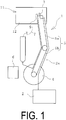
- FIG. 1
- is an explanatory diagram illustrating a cleaning device for a vulcanization mold according to an embodiment of the present invention in a plan view.
- FIG. 2
- is an explanatory diagram illustrating a molding surface of a studless-tire vulcanization mold in a plan view.
- FIG. 3
- is an explanatory diagram illustrating a molding surface of a cast splicing mold in an enlarged cross-sectional view.
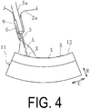
- FIG. 4
- is an explanatory diagram illustrating a state of cleaning the mold in a side view.
- FIG. 5
- is an explanatory diagram illustrating a state of cleaning the mold in a front view.
- FIG. 6
- is an explanatory diagram illustrating, in a front view, a state where a space surrounded in an irradiation range and a surrounding range thereof by a cover is filled with inert gas and the mold is being cleaned.
- FIG. 7
- is an explanatory diagram illustrating the cover and the mold of
FIG. 6 in a plan view. - FIG. 8
- is an explanatory diagram illustrating a state of cleaning the mold by a cleaning device according to another embodiment of the present invention in a cross-sectional view.
- FIG. 9
- is an explanatory diagram illustrating the inside of the cover of
FIG. 8 in a plan view. - A cleaning device and a method for cleaning a vulcanization mold of the present invention is described based on embodiments illustrated in the drawings. Although what is to be cleaned is a tire vulcanization mold in the following description, the present invention can also be used to clean vulcanization molds for vulcanizing rubber products other than tires.
- A
cleaning device 1 for a vulcanization mold according to an embodiment illustrated inFIG. 1 is configured to remove a dirt X adhering to a cleaning target portion of a tire vulcanization mold 11 (hereinafter, referred to as a mold 11) with a laser beam L. Thecleaning device 1 includes alaser oscillator 2, alaser head 3, and a gas supply unit 7 that supplies an inert gas G. Thelaser oscillator 2 and thelaser head 3 are connected by anoptical fiber cable 2a. The gas supply unit 7 includes a tank 8 containing the inert gas G, and asupply nozzle 9 connected via a hose to the tank 8. - The
cleaning device 1 further includes: anarm 5 to which thelaser head 3 is attached; and a controller 6 that controls the movement of thearm 5 and thelaser head 3. Thearm 5 is rotatably attached to an arm base 4 and is configured such that a plurality ofarm portions laser head 3 is removably attached to an end portion of thearm 5. - The movement of the
arm 5 is controlled, and thus thelaser head 3 can be moved to a desired three-dimensional position. Since thesupply nozzle 9 is also attached to the end portion of thearm 5, an end of thesupply nozzle 9 can always be directed in the irradiation direction of the laser beam L. - The laser beam L supplied by the
laser oscillator 2 is transmitted through theoptical fiber cable 2a to the laser head 3.The laser beam L is radiated from thelaser head 3 to amolding surface 12 of themold 11, which is a cleaning target portion. - The gas supply unit 7 supplies the inert gas G housed in the tank 8 from the
supply nozzle 9 toward an irradiation range of themolding surface 12 or a surrounding range of the irradiation range irradiated with the laser beam L. Thus, the irradiation range is brought into an atmosphere of the inert gas G. - The laser beam L in the related art used for cleaning the
mold 11 can be applied to the laser beam L. Specific specifications of the laser beam L to be radiated are, for example, as follows. The type of the laser beam L is not particularly specified, but a Yb-YAG laser beam (wavelength of 1030 nm) and an Nd-YAG laser beam (wavelength of 1064 nm) are preferable. The output of the light source of the laser beam L is 1 W or greater and 5 kW or less, the pulse width is 1 ns or greater and 500 ns or less, the pulse energy is 1 mJ or greater and 0.1 J or less, and the pulse frequency is 1 kHz or greater and 100 kHz or less. The fluence is 0.5 J/m2 or greater and 4.0 J/m2 or less, the beam diameter (diameter) is 0.1 mm or greater and 3 mm or less, and the pulse overlap is 0 or greater and 100% or less. The line overlap is 0 or greater and 100% or less. - In the present embodiment, the
laser head 3 that radiates the laser beam L with pinpoint precision is provided; however, thelaser head 3 is not limited to such a type. For example, the type of thelaser head 3 internally including a galvano mirror can be applied, in which the laser beam L is scanned in the width direction such that a wide range can be irradiated. Thelaser head 3 is not limited to a single laser head, and specifications including a plurality of the laser heads 3 may be provided. The same type of the plurality of laser heads 3 can be provided. Alternatively, specifications including different types of the laser heads 3 in combination can be provided. - The
mold 11 to be cleaned is not limited to the normal type of mold. For example, a studless-tire vulcanization mold illustrated inFIG. 2 can be also applied. Groove formingprojections 13 andsipe forming projections 14 are projected on themolding surface 12 of themold 11. Thegroove forming projections 13 are casted integrally with a base material of themold 11, and thesipe forming projections 14 are attached to themolding surface 12, as a separate material from the base material of themold 11. The base material of themold 11 is usually made of aluminum and thesipe forming projections 14 are made of steel or the like. - The thickness of the
sipe forming projections 14 is about from 0.4 to 1.2 mm. Thus, the surface and root portion of thesipe forming projections 14 or thegroove forming projections 13 with the small thickness are portions from which the dirt X is difficult to be removed in the event of cleaning themold 11. In addition, C arrow, R arrow, and W arrow that are illustrated in the diagram respectively indicate a circumferential direction, a radial direction, and a width direction of a tire that is to be inserted into themold 11 and vulcanized therein. - Another example of the different type of
mold 11 to be cleaned is a cast splicing mold for pneumatic tire vulcanization illustrated inFIG. 3 . Themold 11 is produced by so-called cast splicing in which afirst casting part 15 is casted and asecond casting part 16 is casted thereafter. The casted melting metal is solidified and shrunk, and thus a small gap g is defined in acast splicing part 18 between thefirst casting part 15 and thesecond casting part 16. The size of the small gap g is, for example, from 5 to 80 µm. Anexhaust hole 17 in communication with the small gap g is defined. In themold 11, unnecessary air or gas when the tire is vulcanized is discharged from themolding surface 12 to theexhaust hole 17 through the small gap g, and then discharged out of themold 11 through theexhaust hole 17. The small gap g is a part from which the dirt X is difficult to be removed in the event of cleaning themold 11. - Next, a method for cleaning the
mold 11 is described. - Cleaning of the
mold 11 is performed in a cleaning booth that serves as a closed space. In the present embodiment, since thesector molds 11 are cleaned one by one, thesingle sector mold 11 is installed in a predetermined position as illustrated inFIG. 1 . Thereafter, the movement of thearm 5 is controlled, and thus, as illustrated inFIGS. 4 and5 , thelaser head 3 is moved along themolding surface 12 to be cleaned. While thelaser head 3 is being moved in this way, themolding surface 12 is irradiated with the laser beam L supplied from thelaser oscillator 2. Here, the inert gas G is supplied from thesupply nozzle 9 toward the irradiation range where the laser beam L is radiated, and thus the irradiation range is brought into the atmosphere of the inert gas G. - Nitrogen gas, argon gas, or the like can be used as the inert gas G. From the perspective of availability, cost, handling, and the like, it is preferable to use nitrogen gas as the inert gas G.
- The dirt X adhering to the
molding surface 12 is removed and cleaned by the radiated laser beam L. Thelaser head 3 is moved to cover the range of themolding surface 12 as a cleaning target portion while radiating the laser beam L under the atmosphere of the inert gas G and thus cleans themolding surface 12. - In the present embodiment, the laser beam L is radiated while the inert gas G is being supplied toward the irradiation range of the laser beam L or a surrounding range thereof. This makes it advantageous to reduce the amount of the inert gas G used, and in the meantime, the inert gas G in the irradiation range is maintained at a high concentration.
- Since the inert gas G is likely to accumulate downward in the atmosphere, the laser beam L can be radiated in a state where, as illustrated in
FIGS. 6 and7 , a space S covering the irradiation range and a surrounding range of the irradiation range is filled with the inert gas G. In the present embodiment, acover 10 adapted to surround the space S in the irradiation range and a surrounding range thereof is provided to bring a state where the inert gas G is supplied into and fills the space S. - The
cover 10 includes anopening 10a that extends in the tire lateral direction on the upper surface thereof. Thelaser head 3 irradiates themolding surface 12 with the laser beam L while moving in the extending direction of theopening 10a. Since thecover 10 is movable with respect to themold 11, thecover 10 is moved in accordance with the movement of thelaser head 3 in the tire circumferential direction, and thus theentire molding surface 12 can be cleaned. - The
cover 10 as just described is provided, and thus diffusion of the inert gas G is inhibited, and the inert gas G in the space S is easily maintained at a high concentration. However, since the inert gas G does not rapidly diffuse in the atmosphere, thecover 10 is omitted, and the inert gas G is simply supplied into the space S to bring the space S into a state of being filled with the inert gas G. - The
mold 11 cleaned as just described is used, and thus unvulcanized rubber (green tire) is vulcanized to produce a tire, and then the tire (vulcanized rubber) is released from themold 11. According to the present invention, there occurs no defect such as a rubber defect resulting from the adhering and remaining of the vulcanized rubber on themolding surface 12 cleaned with the laser beam L. - The inventors of the present invention have confirmed that when the laser beam L is radiated onto the
molding surface 12 in the atmosphere as in the related art to remove the dirt X and then the cleanedmolding surface 12 is enlarged and observed, ultrafine protrusions that may not be formed in other cleaning methods are formed. The ultrafine projections have nearly the height of nm level (about 1 nm to several hundred nm). On the other hand, the inventors of the present invention have confirmed that when themolding surface 12 is cleaned with the laser beam L radiated under the atmosphere of the inert gas G, the aforementioned ultrafine protrusions are prevented from being formed on the cleanedmolding surface 12. - Accordingly, it is supposed that the ultrafine protrusions formed on the
molding surface 12 cleaned with the laser beam L radiated cause the vulcanized rubber to adhere and remain on the cleanedmolding surface 12 when the vulcanized rubber is released in a vulcanization step. In the present invention, the dirt X is removed with the laser beam L under the atmosphere of the inert gas G at the high concentration. In other words, the laser beam L is radiated in an atmosphere from which air (a normal atmospheric component) is eliminated, and thus ultrafine protrusions may be prevented from being formed on themolding surface 12 cleaned with the laser beam L. Consequently, a simple means of bringing the irradiation range of the laser beam L into the atmosphere of the inert gas G can prevent a defect such as a rubber defect in a rubber product, which is caused by the adhering and remaining of the vulcanized rubber on a cleaning target portion cleaned with the laser beam L. - The concentration of the inert gas G in the irradiation range of the laser beam L is set to an appropriate range, and the amount of the inert gas G supplied from the gas supply unit 7 is controlled to be within the set appropriate concentration range. The appropriate concentration range of the inert gas G corresponds to, for example, atmospheres of the inert gas G at a plurality of different concentration levels under which the
molding surface 12 is cleaned with the laser beam L set in certain irradiation conditions. For themolding surface 12 cleaned under the atmosphere at each of the concentration levels, how much of the vulcanized rubber adheres and remains when being released from the mold is grasped. Then, the concentration of the inert gas G when no vulcanized rubber adheres and remains on themolding surface 12 may be set as the appropriate concentration range of the inert gas G in the certain irradiation conditions of the laser beam L. - Note that the main purpose of supplying the inert gas G is to not form the aforementioned ultrafine protrusions on the
molding surface 12 from which the dirt X is removed by radiating the laser beam L. Accordingly, it is not necessary to blow off the removed dirt X by the jet flow of the inert gas G supplied from thesupply nozzle 9. Consequently, in the present invention, the inert gas G is supplied so that the dirt X removed by radiating the laser beam L is not blown off by the jet flow of the inert gas G, and it is sufficient that the irradiation range in which the laser beam L is radiated is brought into the atmosphere of the inert gas G. - In the embodiment of the
cleaning device 1 illustrated inFIGS. 8 and9 , the plurality ofsector molds 11 are cleaned at a time. In other words, the number ofsector molds 11 required to vulcanize a single green tire is disposed in an annular shape with themolding surface 12 disposed inward thereon. Each of themolds 11 is mounted on apedestal 10b. Eachmold 11 is covered by thecover 10 having theopening 10a in the upper surface thereof. - The
arm 5 movable in the up-down direction is inserted in theopening 10a to extend in the up-down direction at the center of the annular shape of themolds 11 disposed in the annular shape. Thelaser head 3 is attached to the end portion of thearm 5. Thesupply nozzle 9 is attached to the upper surface of thecover 10. Thearm 5 is rotatable about the axial center in the up-down direction, and thelaser head 3 also rotates with thearm 5. Thelaser head 3 is capable of oscillating up and down. - In the event of cleaning the
molding surface 12 of eachmold 11, the laser beam L is radiated from thelaser head 3 while thearm 5 is being rotated. In addition, the up and down movement of thearm 5 and the up and down oscillation of thelaser head 3 are performed as appropriate, and thus thelaser head 3 is moved to the required range of themolding surface 12 and then cleans themolding surface 12 with the laser beam L. The inert gas G is supplied from thesupply nozzle 9 to the inside of thecover 10, and thus the space S covering the irradiation range of themolding surface 12 irradiated with the laser beam L and a surrounding range thereof is brought into a state of being filled with the inert gas G. As just described, the irradiation range of the laser beam L is brought into the atmosphere of the inert gas G, and cleaning is performed. - In the present embodiment, advantageously, the
multiple molds 11 can be cleaned at a time. Rather than a structure in which thearm 5 is rotated about the axial center in the up-down direction, thepedestal 10b can be configured to rotate about the axial center of thearm 5 in the up-down direction. Additionally, in the present embodiment, each of themolds 11 disposed in an annular shape prevents diffusion of the inert gas G supplied into the space S. In other words, each of themolds 11 also functions as thecover 10, and thus, even when thecover 10 is omitted, a state where the space S filled with the inert gas G can be maintained for a relatively long period of time. - According to the present invention, the dirt X can be efficiently removed even when the
mold 11 includes themolding surface 12 having a complex shape, such as a studless-tire vulcanization mold or a cast splicing mold for pneumatic tire vulcanization. In addition, at the time of releasing the vulcanized rubber in the vulcanization step, a rubber defect in the tire can be prevented from being caused by the adhering and remaining of the vulcanized rubber on the cleanedmolding surface 12. - Note that the present invention is not limited to the
molding surface 12 and can alternatively be applied in a case where facing surfaces (opposed surfaces) of theadjacent molds 11 are cleaned as cleaning target portions. - Molding surfaces were cleaned in two ways such as a case (Conventional Example) where a molding surface of a studless-tire vulcanization mold for a passenger vehicle is irradiated with a laser beam and an irradiation range is brought into the atmosphere; and a case (Example) where such an irradiation range is brought into an atmosphere of nitrogen gas. The differences between Conventional Example and Examples were only whether the irradiation range was in the atmosphere or in the atmosphere of nitrogen gas, and other conditions were the same. In Example, the nitrogen gas was supplied from a common nitrogen gas cylinder (volume 47 L) toward the molding surface. The supply amount of nitrogen gas was set to not less than 10 cc/sec.
- Green tires were vulcanized with the mold cleaned. Then, it was confirmed whether a rubber defect was caused in each of the tires by the adhering and remaining of vulcanized rubber on the molding surface when the vulcanized rubber was released from the mold (the number of samples N is five tires). As a result, rubber defects generated in all of the tires in Conventional Example while there were no rubber defects in the tires in Example.
-
- 1 Cleaning device
- 2 Laser oscillator
- 2a Optical fiber cable
- 3 Laser head
- 4 Arm base
- 5 Arm
- 5a, 5b Arm portion
- 6 Controller
- 7 Gas supply unit
- 8 Tank
- 9 Supply nozzle
- 10 Cover
- 10a Opening
- 10b Pedestal
- 11 Vulcanization mold
- 12 Molding surface
- 13 Groove forming projection
- 14 Sipe forming projection
- 15 First casting part
- 16 Second casting part
- 17 Exhaust hole
- 18 Cast splicing part
- L Laser beam
- S Space
- X Dirt
Claims (9)
- A cleaning device for a mold, comprising:a laser oscillator; anda laser head configured to irradiate a cleaning target portion of the vulcanization mold with a laser beam supplied from the laser oscillator, the cleaning device comprising a gas supply unit configured to bring an irradiation range of the cleaning target portion irradiated with the laser beam into an atmosphere of inert gas.
- The cleaning device for a vulcanization mold according to claim 1, wherein the gas supply unit comprises a supply nozzle configured to supply the inert gas toward the irradiation range or a surrounding range of the irradiation range.
- The cleaning device for a vulcanization mold according to claim 1, wherein
the gas supply unit comprises: a cover adapted to surround a space covering the irradiation range and a surrounding range of the irradiation range in the irradiation range and the surrounding range of the irradiation range; and a supply nozzle configured to supply the inert gas into the space. - A method for cleaning a vulcanization mold by irradiating a cleaning target portion of the vulcanization mold with a laser beam, the method comprising:
bringing an irradiation range of the cleaning target portion irradiated with the laser beam into an atmosphere of inert gas. - The method for cleaning a vulcanization mold according to claim 4, wherein
the laser beam is radiated while the inert gas is being supplied toward the irradiation range or a surrounding range of the irradiation range. - The method for cleaning a vulcanization mold according to claim 4, wherein
the laser beam is radiated in a state where a space covering the irradiation range and a surrounding range of the irradiation range is filled with the inert gas. - The method for cleaning a vulcanization mold according to claim 6, wherein
a cover surrounding the space in the irradiation range and the surrounding range of the irradiation range is provided to bring a state where the inert gas is supplied into and fills the space. - The method for cleaning a vulcanization mold according to any one of claims 4 to 7, wherein
nitrogen gas is used as the inert gas. - The method for cleaning a vulcanization mold according to any one of claims 4 to 8, wherein
the vulcanization mold is a studless-tire vulcanization mold or a cast splicing mold for pneumatic tire vulcanization.
Applications Claiming Priority (2)
| Application Number | Priority Date | Filing Date | Title |
|---|---|---|---|
| JP2018022230A JP6590010B2 (en) | 2018-02-09 | 2018-02-09 | Vulcanizing mold cleaning apparatus and method |
| PCT/JP2018/042395 WO2019155715A1 (en) | 2018-02-09 | 2018-11-16 | Device and method for cleaning vulcanizing mold |
Publications (2)
| Publication Number | Publication Date |
|---|---|
| EP3750680A1 true EP3750680A1 (en) | 2020-12-16 |
| EP3750680A4 EP3750680A4 (en) | 2021-11-03 |
Family
ID=67548846
Family Applications (1)
| Application Number | Title | Priority Date | Filing Date |
|---|---|---|---|
| EP18905562.7A Withdrawn EP3750680A4 (en) | 2018-02-09 | 2018-11-16 | Device and method for cleaning vulcanizing mold |
Country Status (4)
| Country | Link |
|---|---|
| US (1) | US11897218B2 (en) |
| EP (1) | EP3750680A4 (en) |
| JP (1) | JP6590010B2 (en) |
| WO (1) | WO2019155715A1 (en) |
Families Citing this family (1)
| Publication number | Priority date | Publication date | Assignee | Title |
|---|---|---|---|---|
| JP6915649B2 (en) * | 2019-07-03 | 2021-08-04 | 横浜ゴム株式会社 | Tire vulcanization mold and tire manufacturing method |
Family Cites Families (30)
| Publication number | Priority date | Publication date | Assignee | Title |
|---|---|---|---|---|
| US5637245A (en) * | 1995-04-13 | 1997-06-10 | Vernay Laboratories, Inc. | Method and apparatus for minimizing degradation of equipment in a laser cleaning technique |
| IT1282722B1 (en) * | 1996-03-01 | 1998-03-31 | Pirelli | METHOD AND APPARATUS FOR THE CLEANING OF VULCANIZATION MOLDS OF ELASTOMERIC MATERIAL ARTICLES |
| JPH10128220A (en) * | 1996-10-28 | 1998-05-19 | Suzuki Motor Corp | Painting defect removal equipment |
| JPH1199524A (en) * | 1997-09-29 | 1999-04-13 | Fuji Industries:Kk | Mold cleaning device |
| CA2314874A1 (en) * | 1998-02-20 | 1999-08-26 | Geary Victor Soska | Robotic laser tire mold cleaning system and method of use |
| US6369353B1 (en) * | 1998-02-20 | 2002-04-09 | The Goodyear Tire & Rubber Company | Robotic laser tire mold cleaning system and method of use |
| DE19933195A1 (en) * | 1999-07-15 | 2001-01-18 | Forma Formen Und Maschb Gmbh | Device and method for cleaning and / or coating the mold surface of a mold |
| JP2002118308A (en) * | 2000-10-06 | 2002-04-19 | Komatsu Ltd | Casing for laser device, its production method, and its cleaning method |
| RU2297886C2 (en) * | 2005-06-06 | 2007-04-27 | Евгений Михайлович Борисов | Method for cleaning surface and apparatus for performing the same |
| WO2010055277A1 (en) * | 2008-11-13 | 2010-05-20 | Qinetiq Limited | Improved laser ablation technique |
| KR100905253B1 (en) * | 2008-11-27 | 2009-06-29 | 이노크린 주식회사 | Tire mold automatic cleaning device |
| KR101026702B1 (en) * | 2008-12-01 | 2011-04-08 | 김정래 | Tire mold cleaning device |
| DE102012107225A1 (en) * | 2012-08-07 | 2014-02-13 | enotech AG | Apparatus and method for cleaning vulcanization molds |
| DE102013220066B3 (en) * | 2013-10-02 | 2014-12-18 | 4Jet Technologies Gmbh | Method for cleaning a surface of a cavity |
| JP5835400B2 (en) * | 2014-05-09 | 2015-12-24 | 横浜ゴム株式会社 | Mold cleaning system |
| JP2015232110A (en) * | 2014-05-13 | 2015-12-24 | 住友ゴム工業株式会社 | Rubber composition and tire |
| JP5892198B2 (en) * | 2014-06-26 | 2016-03-23 | 横浜ゴム株式会社 | Mold cleaning system |
| JP6495594B2 (en) | 2014-08-01 | 2019-04-03 | 住友ゴム工業株式会社 | Tire mold cleaning method |
| KR101661944B1 (en) * | 2015-01-21 | 2016-10-05 | 주식회사 제펠 | Laser cleaning apparatus for removing scrap of mold |
| US10082166B2 (en) * | 2015-03-12 | 2018-09-25 | Ut-Battelle, Llc | Laser nanostructured surface preparation for joining materials |
| JP6260720B2 (en) * | 2015-11-05 | 2018-01-17 | 横浜ゴム株式会社 | Mold cleaning system |
| CN105618436A (en) * | 2016-02-24 | 2016-06-01 | 青岛万龙智控科技有限公司 | Laser cleaning manipulator |
| CN105666753A (en) * | 2016-02-24 | 2016-06-15 | 青岛万龙智控科技有限公司 | Automatic laser cleaning equipment |
| KR101735373B1 (en) * | 2016-03-11 | 2017-05-16 | 주식회사 제펠 | Laser cleaning apparatus for removing scrap of upper mold |
| CN206264223U (en) * | 2016-12-01 | 2017-06-20 | 重庆市永川区泰兴机械厂 | Suspension type tire-mold cleaning machine |
| CN206264224U (en) * | 2016-12-01 | 2017-06-20 | 重庆市永川区泰兴机械厂 | Three cleaning machines of tire-mold gas-liquid light |
| CN206326775U (en) * | 2016-12-01 | 2017-07-14 | 重庆市永川区泰兴机械厂 | Tire-mold noble gas laser cleaning machine |
| DE202017103770U1 (en) * | 2017-06-23 | 2017-07-18 | 4Jet Technologies Gmbh | Portable laser device |
| CN107377532A (en) * | 2017-08-25 | 2017-11-24 | 济南高能清扬激光清洗有限公司 | A kind of compound cleaning method of rubber mould |
| EP3723970B1 (en) * | 2017-12-14 | 2024-12-11 | Compagnie Generale Des Etablissements Michelin | Method and apparatus for cleaning a vulcanising mould |
-
2018
- 2018-02-09 JP JP2018022230A patent/JP6590010B2/en active Active
- 2018-11-16 EP EP18905562.7A patent/EP3750680A4/en not_active Withdrawn
- 2018-11-16 US US16/968,536 patent/US11897218B2/en active Active
- 2018-11-16 WO PCT/JP2018/042395 patent/WO2019155715A1/en not_active Ceased
Also Published As
| Publication number | Publication date |
|---|---|
| EP3750680A4 (en) | 2021-11-03 |
| JP2019136937A (en) | 2019-08-22 |
| US20210039345A1 (en) | 2021-02-11 |
| US11897218B2 (en) | 2024-02-13 |
| JP6590010B2 (en) | 2019-10-16 |
| WO2019155715A1 (en) | 2019-08-15 |
Similar Documents
| Publication | Publication Date | Title |
|---|---|---|
| US10857747B2 (en) | Mold cleaning system | |
| US11072139B2 (en) | Mold cleaning system | |
| US10471632B2 (en) | Mold cleaning system | |
| CN114025948B (en) | Tire vulcanization mold and tire manufacturing method | |
| EP3141381B1 (en) | Release agent removal method, and a tire | |
| US11897218B2 (en) | Cleaning device and method for cleaning vulcanization mold | |
| JP7597993B2 (en) | How to clean vulcanization molds | |
| RU2811590C2 (en) | Tyre manufacturing method | |
| JP7401730B2 (en) | Vulcanization mold cleaning method and device and tire manufacturing method | |
| CN119304033A (en) | Molding system and molding method |
Legal Events
| Date | Code | Title | Description |
|---|---|---|---|
| STAA | Information on the status of an ep patent application or granted ep patent |
Free format text: STATUS: THE INTERNATIONAL PUBLICATION HAS BEEN MADE |
|
| PUAI | Public reference made under article 153(3) epc to a published international application that has entered the european phase |
Free format text: ORIGINAL CODE: 0009012 |
|
| STAA | Information on the status of an ep patent application or granted ep patent |
Free format text: STATUS: REQUEST FOR EXAMINATION WAS MADE |
|
| 17P | Request for examination filed |
Effective date: 20200717 |
|
| AK | Designated contracting states |
Kind code of ref document: A1 Designated state(s): AL AT BE BG CH CY CZ DE DK EE ES FI FR GB GR HR HU IE IS IT LI LT LU LV MC MK MT NL NO PL PT RO RS SE SI SK SM TR |
|
| AX | Request for extension of the european patent |
Extension state: BA ME |
|
| DAV | Request for validation of the european patent (deleted) | ||
| DAX | Request for extension of the european patent (deleted) | ||
| A4 | Supplementary search report drawn up and despatched |
Effective date: 20211004 |
|
| RIC1 | Information provided on ipc code assigned before grant |
Ipc: B23K 35/38 20060101ALI20210928BHEP Ipc: B23K 26/402 20140101ALI20210928BHEP Ipc: B23K 26/142 20140101ALI20210928BHEP Ipc: B29D 30/06 20060101ALI20210928BHEP Ipc: B29L 30/00 20060101ALI20210928BHEP Ipc: B29C 33/72 20060101AFI20210928BHEP |
|
| STAA | Information on the status of an ep patent application or granted ep patent |
Free format text: STATUS: EXAMINATION IS IN PROGRESS |
|
| 17Q | First examination report despatched |
Effective date: 20230811 |
|
| RAP3 | Party data changed (applicant data changed or rights of an application transferred) |
Owner name: THE YOKOHAMA RUBBER CO., LTD. |
|
| STAA | Information on the status of an ep patent application or granted ep patent |
Free format text: STATUS: THE APPLICATION IS DEEMED TO BE WITHDRAWN |
|
| 18D | Application deemed to be withdrawn |
Effective date: 20231222 |