EP3750472A1 - Kathetereinrichtung zum platzieren eines sensors - Google Patents
Kathetereinrichtung zum platzieren eines sensors Download PDFInfo
- Publication number
- EP3750472A1 EP3750472A1 EP19179895.8A EP19179895A EP3750472A1 EP 3750472 A1 EP3750472 A1 EP 3750472A1 EP 19179895 A EP19179895 A EP 19179895A EP 3750472 A1 EP3750472 A1 EP 3750472A1
- Authority
- EP
- European Patent Office
- Prior art keywords
- coupling
- sensor
- sensor device
- catheter device
- locking element
- Prior art date
- Legal status (The legal status is an assumption and is not a legal conclusion. Google has not performed a legal analysis and makes no representation as to the accuracy of the status listed.)
- Granted
Links
- 0 CCC(C[C@@](C)(CC1CC2)C(CCCCCCCC3C4)/*1=C4/*(C1)C3C(C)CC21N)C(C(CN)O)I Chemical compound CCC(C[C@@](C)(CC1CC2)C(CCCCCCCC3C4)/*1=C4/*(C1)C3C(C)CC21N)C(C(CN)O)I 0.000 description 1
Images








Classifications
-
- A—HUMAN NECESSITIES
- A61—MEDICAL OR VETERINARY SCIENCE; HYGIENE
- A61B—DIAGNOSIS; SURGERY; IDENTIFICATION
- A61B5/00—Measuring for diagnostic purposes; Identification of persons
- A61B5/02—Detecting, measuring or recording for evaluating the cardiovascular system, e.g. pulse, heart rate, blood pressure or blood flow
- A61B5/021—Measuring pressure in heart or blood vessels
- A61B5/0215—Measuring pressure in heart or blood vessels by means inserted into the body
-
- A—HUMAN NECESSITIES
- A61—MEDICAL OR VETERINARY SCIENCE; HYGIENE
- A61B—DIAGNOSIS; SURGERY; IDENTIFICATION
- A61B5/00—Measuring for diagnostic purposes; Identification of persons
- A61B5/68—Arrangements of detecting, measuring or recording means, e.g. sensors, in relation to patient
- A61B5/6846—Arrangements of detecting, measuring or recording means, e.g. sensors, in relation to patient specially adapted to be brought in contact with an internal body part, i.e. invasive
- A61B5/6847—Arrangements of detecting, measuring or recording means, e.g. sensors, in relation to patient specially adapted to be brought in contact with an internal body part, i.e. invasive mounted on an invasive device
- A61B5/6852—Catheters
-
- A—HUMAN NECESSITIES
- A61—MEDICAL OR VETERINARY SCIENCE; HYGIENE
- A61B—DIAGNOSIS; SURGERY; IDENTIFICATION
- A61B5/00—Measuring for diagnostic purposes; Identification of persons
- A61B5/68—Arrangements of detecting, measuring or recording means, e.g. sensors, in relation to patient
- A61B5/6846—Arrangements of detecting, measuring or recording means, e.g. sensors, in relation to patient specially adapted to be brought in contact with an internal body part, i.e. invasive
- A61B5/6867—Arrangements of detecting, measuring or recording means, e.g. sensors, in relation to patient specially adapted to be brought in contact with an internal body part, i.e. invasive specially adapted to be attached or implanted in a specific body part
- A61B5/6869—Heart
-
- A—HUMAN NECESSITIES
- A61—MEDICAL OR VETERINARY SCIENCE; HYGIENE
- A61B—DIAGNOSIS; SURGERY; IDENTIFICATION
- A61B5/00—Measuring for diagnostic purposes; Identification of persons
- A61B5/68—Arrangements of detecting, measuring or recording means, e.g. sensors, in relation to patient
- A61B5/6846—Arrangements of detecting, measuring or recording means, e.g. sensors, in relation to patient specially adapted to be brought in contact with an internal body part, i.e. invasive
- A61B5/6867—Arrangements of detecting, measuring or recording means, e.g. sensors, in relation to patient specially adapted to be brought in contact with an internal body part, i.e. invasive specially adapted to be attached or implanted in a specific body part
- A61B5/6876—Blood vessel
-
- A—HUMAN NECESSITIES
- A61—MEDICAL OR VETERINARY SCIENCE; HYGIENE
- A61B—DIAGNOSIS; SURGERY; IDENTIFICATION
- A61B2560/00—Constructional details of operational features of apparatus; Accessories for medical measuring apparatus
- A61B2560/04—Constructional details of apparatus
-
- A—HUMAN NECESSITIES
- A61—MEDICAL OR VETERINARY SCIENCE; HYGIENE
- A61B—DIAGNOSIS; SURGERY; IDENTIFICATION
- A61B2560/00—Constructional details of operational features of apparatus; Accessories for medical measuring apparatus
- A61B2560/06—Accessories for medical measuring apparatus
- A61B2560/063—Devices specially adapted for delivering implantable medical measuring apparatus
- A61B2560/066—Devices specially adapted for delivering implantable medical measuring apparatus catheters therefor
Definitions
- the invention relates to a catheter device for placing a sensor device and to a system with a catheter device and a sensor device.
- Such a catheter device comprises a shaft and a coupling device arranged on the shaft for coupling the catheter device to the sensor device which has at least one bracket element.
- Such a catheter device can be used, for example, as a withdrawal catheter for placing a sensor device in the human heart or in another blood vessel.
- a sensor device of the type in question can be designed, for example, as a pressure sensor, temperature sensor, oxygen sensor or flow sensor and is intended to record measurement data within a patient and transmit it to an external device, for example by means of telemetry.
- Such sensor devices can be used, for example, in the context of home monitoring (so-called home monitoring) of seriously ill patients in order to enable monitoring and care of patients in a non-stationary environment.
- Implantable sensor devices for pressure monitoring in the human heart are for example in the articles JH Dreyfuss et al., "Prevent the Next Heart Attack: Implant a CardioMEMS Device in a Heart Failure Patient," MD / alert, Feb. 2016 ; PB Adamson et al., “Champion * Trial Rational and Design: The Long-Term Safety and Clinical Efficacy of a Wireless Pulmonary Artery Pressure Monitoring System," Journal of Cardiac Failure, Vol. 17, No.1, 2011 ; and EY Chow, "Fully Wireless Implantable Cardiovascular Pressure Monitor Integrated with a Medical Stent", IEEE Transactions on Biomedical Engineering, Vol. 57, no. 6, 2010 described.
- the object is to provide a catheter device for placing a sensor device, as well as a system with a catheter device and a sensor device, which enable a simple, flexible and reliable placement of a sensor device. If necessary, it should be possible to grasp the sensor device again to correct the sensor position or to remove the sensor device.
- the coupling device has a coupling element and a locking element that is adjustable relative to the coupling element.
- the coupling element has at least one engagement section with which the at least one bracket element of the sensor device can be brought into engagement, wherein the locking element is designed to lock the at least one bracket element on the at least one engagement section in a coupled position and is adjustable to the coupling element, to release the at least one bracket element for releasing from the at least one engagement portion.
- the catheter device uses a coupling device in order to produce a coupling to a sensor device to be implanted.
- the sensor device can be gripped via the coupling device, so that in a coupled position the sensor device is firmly connected to the catheter device.
- the coupling is established in that the sensor device engages in the coupled position with one or more bracket elements in one or more engagement sections of a coupling element of the coupling device.
- the engagement sections can be shaped, for example, in the manner of undercuts and thus establish a positive connection between the sensor device and the coupling device.
- the positive connection is blocked by a locking element in such a way that the bracket elements of the sensor device in the coupled position cannot easily disengage from the engagement sections of the coupling element, at least not without actuation of the locking element, but rather reliably and resiliently on the coupling device via the coupling device Catheter device are held.
- the sensor device In the coupled position, the sensor device can be implanted in a patient by means of the catheter device and, for this purpose, brought to a predetermined location in the human heart or in another vessel. Once a destination has been reached, the locking element can be actuated in order to release the bracket elements of the sensor device and thus enable the sensor device to be released from the coupling device and thus from the catheter device.
- the coupling can be canceled by adjusting the locking element with a comparatively small stroke.
- the locking element By adjusting the locking element, the at least one engagement section of the coupling element is released so that the at least one bracket element of the sensor device can be easily disengaged from the engagement section.
- the locking element serves to lock the at least one bracket element, when it is in engagement with the at least one engagement section of the coupling element, so that the at least one bracket element cannot disengage from the engagement section.
- the locking element is in a blocking position in such a spatial positional relationship to the engagement section that the bracket element cannot be removed from the engagement section. Only when the locking element is actuated to release the coupling can the bracket element be removed from the associated engagement section and thus the sensor device can be decoupled from the catheter device.
- the coupling device can be constructed with a comparatively small installation space, which makes it possible to use a catheter device with a thin shaft (diameter for example 6F or 7F or 1.8 mm to 2.4 mm).
- the coupling element is firmly connected to a section of the shaft, for example in the region of a distal end of the shaft.
- the at least one engagement section is shaped to produce the coupling on the coupling element such that the sensor device can be brought into engagement with the engagement section in a simple and reliable manner via the at least one bracket element and is locked in a coupled position via the locking element to the coupling element.
- the locking element can be adjusted linearly to the coupling element, for example, along an actuation direction.
- the coupling element can be guided to the locking element along the actuation direction so that the locking element can be adjusted between a locking position for locking the at least one bracket element in engagement with the at least one engagement section of the coupling element and a release position for releasing the sensor device.
- the coupling element has a distal edge that is remote from the shaft and extends, for example, along a plane directed transversely to the direction of longitudinal extension of the shaft and is formed circumferentially on the coupling element, for example sleeve-shaped.
- at least one recess is formed in the edge, on which the at least one engagement section is shaped like an undercut.
- each bracket element of the sensor device By engaging in the recess and the engagement section formed on the recess, each bracket element of the sensor device can thus be coupled to the coupling element, wherein in the coupled position the engagement of the bracket element in the engagement section of the coupling element is blocked via the locking element in such a way that the bracket element is not can be easily disengaged from the engagement portion - at least not without actuation of the locking element.
- the locking element has at least one engagement groove for receiving the at least one bracket element in the coupled position.
- the locking element can, for example, have a body lying in the sleeve-shaped coupling element with a distal end facing outwards in the distal direction. On this distal end face, one or more engagement grooves can be formed in such a way that in the coupled position of the sensor device, each bracket element of the sensor device engages in an engagement groove of the locking element.
- the engagement grooves can, for example, extend radially to the (linearly directed) actuation direction and are aligned with the engagement section in the coupled position of the sensor device in such a way that each bracket element is blocked by engaging the engagement groove with the respectively assigned engagement section and thus not disengaged from the engagement section can be brought.
- the coupling device has a pulling element which is connected to the locking element and extends along the shaft for adjusting the locking element.
- the tension element is used to actuate the locking element and can be subjected to tensile loading in order in this way to adjust the locking element in the actuation direction relative to the coupling element.
- the pulling element can for example extend from the coupling device to a handle arranged at the proximal end of the shaft and be coupled to an actuating element of the handle in such a way that a pulling force is exerted on the pulling element by actuating the actuating element and the locking element is relatively in the actuating direction can be adjusted to the coupling element of the coupling device.
- the handle is arranged on the proximal end of the shaft of the catheter device and can thus be actuated outside the patient's body in order to allow the sensor device to be positioned as intended the coupling in the patient between the sensor device and the coupling device or, if necessary, to grip the sensor device again to correct the position of the sensor device or to remove the sensor device from the patient.
- the actuating element can be rotated to act on the pulling element to adjust the locking element on the handle, the handle, for example, having an anti-twist device which prevents unintentional actuation of the actuating element and thus unintentional release before the sensor device is properly positioned.
- the coupling device has an elastic element arranged on the coupling element and acting between the coupling element and the locking element.
- the elastic element can interact, for example, with a conical section formed on the body of the locking element, in such a way that when the locking element is adjusted in the actuating direction to cancel the coupling of the sensor device with the coupling device, the elastic element is elastically deformed and an elastic counter-tension is applied against the Actuating direction exerts on the locking element.
- the locking element can be automatically reset after actuation, so that the locking element automatically returns to a starting position corresponding to the coupling position when no more tensile forces are exerted on the tension element.
- the elastic element can - additionally or alternatively to provide an elastic pretension - serve to seal a transition between the coupling element and the shaft of the catheter device.
- the elastic element can be arranged on a bottom section of the coupling element which extends transversely to the actuation direction and separates a receiving space of the coupling element, in which the locking element is accommodated in an adjustable manner, from the shaft of the catheter device.
- the bottom section can have an opening through which the pulling element for actuating the locking element is guided, wherein the elastic element can be arranged in the area of the opening on the bottom section, for example like a sleeve, that a transition between the bottom section and the locking element and thus the opening in the bottom section through which the tension element is passed are sealed moisture-tight.
- the locking element faces the base section with one side that faces away from the distal end face of the locking element that carries the at least one engagement groove.
- the bottom section can also serve as a stop for the locking element and thus define a maximum actuation path for the locking element.
- the shaft has a deflectable shaft segment on which the coupling device is arranged.
- the deflectable shaft segment is shaped in the area of the distal end of the shaft and can be deflected so that the catheter device can be guided in a flexible, controllable manner into anatomically tortuous vessels, for example up to the pulmonary artery, in order to place the sensor device.
- the deflectable shaft segment can, for example, be actuated via the same actuating element on the handle that can also be used to actuate the pulling element of the coupling device. While the pulling element can be actuated to adjust the locking element, for example by rotating the actuating element on the handle, the deflectable shaft segment can be deflected, for example, by linear adjustment of the actuating element on the handle.
- a system comprises a catheter device according to the type described above and a sensor device to be coupled to the coupling device of the catheter device.
- a sensor device can be designed, for example, as a pressure sensor, temperature sensor, oxygen sensor or flow sensor and includes, for example, its own power supply, for example a battery, as well as a communication device, for example for data transmission by means of telemetry, so that the sensor device in the human patient in the implanted state in an autarkic manner Can take on monitoring tasks and transmit data signals to an external facility.
- Such a sensor device comprises, for example, a sensor housing and one or more bracket elements arranged on the sensor housing, which in the coupled position engage with associated engagement sections of the coupling element and thus establish a fixed (but detachable) connection between the sensor device and the catheter device.
- the bracket elements are preferably formed from a super-elastic material and extend on the sensor housing in such a way that the sensor device can be placed in a vessel in an atraumatic manner, that is to say in a way that is gentle on the vessel wall.
- each bracket element can be fastened with a first end on a distal side of the sensor housing and with a second end on a proximal side of the sensor housing facing away from the distal side.
- the bracket element is thus firmly connected to the sensor housing at both ends and forms a loop protruding from the sensor housing.
- the coupling device can act on the bracket elements in order to establish a connection between the sensor device and the catheter device.
- the sensor device can have three identically designed bracket elements which are arranged evenly distributed around the sensor housing.
- the sensor housing can be held approximately in the middle (viewed in a cross-sectional plane perpendicular to a direction of longitudinal extent of the sensor housing directed from proximal to distal) between the bracket elements and in an implanted position via the bracket elements be supported on surrounding vessel walls in such a way that the sensor housing is held approximately in the center of the vessel.
- bracket elements are designed differently and that the sensor housing is not supported in the implanted position in the center of a vessel, but rather, for example, approximately on or even in contact with a vessel wall.
- the catheter device 1 shown has a shaft 10 which is connected at a proximal end 100 to a handle 13 and at a distal end 101 has a coupling device 3 for coupling to a sensor device 2.
- the catheter device 1 is used to implant the sensor device 2 in a vessel of a patient, for example in the human heart or in another blood vessel, in order to implant the sensor device 2, for example designed as a pressure sensor, temperature sensor, oxygen sensor or flow sensor, for example for use in the context of home surveillance ("Home Monitoring") of a seriously ill patient.
- the sensor device 2 shown in a separate view in FIG Fig. 2 , has a sensor housing 20 which, for example, can have a length of approx. 15-20 mm and a diameter of approx. 3-5 mm and encloses electrical and electronic components of the sensor device 2.
- the sensor device 2 can have its own power supply, in particular a battery, a suitable sensor system, a processor and a communication device for telemetric data transmission in order to preprocess recorded sensor signals and transmit them to external devices.
- the sensor device 2 is designed as an atraumatic sensor which can be implanted in a patient in a way that is gentle on the vessel wall.
- the sensor device 2 has bracket elements 21, each made of one superelastic wire, which are evenly distributed around the sensor housing 20 and serve to support the sensor housing 20 against surrounding vessel walls when the sensor device 2 is implanted in a patient.
- the bracket elements 21 are each connected at one end 210 to a distal end of the sensor housing 20 and at their other end 211 to a proximal end of the sensor housing 20, as shown in FIG Fig. 2 can be seen.
- bracket elements 21 can also serve as antennas for communication by means of telemetry.
- the coupling device 3 of the catheter device 1 serves to establish a (releasable) connection between the catheter device 1 and the sensor device 2 in order to implant the sensor device 2 in a patient using the catheter device 1.
- the coupling device 3 in a coupled position establishes a connection between the catheter device 1 and the sensor device 2 in that the bracket elements 21 of the sensor device 2 are attached to the bracket elements 21 via proximally shaped anchor points 212 (see FIG Fig. 2 ) are held on the coupling device 3.
- the bracket elements 21 can be unfolded when the coupling is in place, that is to say they can be in a state in which they are implanted in a human vessel.
- the shaft 10 In the area of its distal end 101, the shaft 10 has a deflectable shaft segment 11 which can be deflected in order to be able to guide the catheter device 1 through tortuous vessels in this way.
- the coupling device 3 is arranged on the deflectable shaft segment 11, so that when the shaft segment 11 is deflected, a sensor device 2 connected to the coupling device 3 is deflected together with the shaft segment 11.
- the coupling device 3 has a coupling element 30 in the form of a sleeve, which is firmly connected to the shaft segment 11 and above it to the shaft 10, for example is glued.
- a locking element 31, which can be adjusted relative to the coupling element 30, around the sensor device, is accommodated within the coupling element 30 2 from the coupled position according to Fig. 4 and thus to enable the sensor device 2 to be released from the coupling device 3 and thus from the catheter device 1, as shown in FIG Fig. 5 is shown.
- the coupling device 3 is shown in different views in Figures 6 to 9 shown.
- recesses 300 are formed in the coupling element 30, each of which forms an engagement section 302 in the manner of an undercut delimited on the outside by a blocking section 301. If the sensor device 2 is coupled to the coupling device 3, then each bracket element 21 with an anchor point 212 lies in one of the engagement sections 302 and is held on the coupling element 30 in a form-fitting manner.
- the blocking section 301 jumps transversely to a separation direction E (see Fig. 9 ) in the area of the respectively assigned recess 300.
- the transition between the blocking section 301 and the recessed engaging section 302 delimited by the blocking section 301 extends obliquely to the separation direction E, as in particular Fig. 6 can be seen.
- the locking element 31 is linearly adjustable along an actuation direction Z within the coupling element 30, as in the transition from Fig. 4 towards Fig. 5 or from Fig. 8 towards Fig. 9 can be seen.
- the locking element 31 is guided in the coupling element 30 and has a body 310 on which on a distal, outwardly facing side, star-shaped engagement grooves 311 are formed which open centrally into an opening 312, as shown, for example Fig. 4 and Fig. 7 can be seen.
- each bracket element 21 of the sensor device 2 engages in one of the engagement grooves 311, each engagement groove 311 being aligned with an associated engagement section 302 of the coupling element 30 and thus the bracket element 21 in the engagement section through engagement of the respective bracket element 21 in the engagement groove 311 302 is blocked, as shown, for example, from a synopsis of Fig. 4 and Fig. 6 can be seen.
- the engaging grooves 311 are removed from the area of the engaging sections 302.
- the bracket elements 21 get out like this Fig. 5 can be seen, disengaged from the engagement grooves 311, so that the bracket elements 21 are no longer locked to the engagement sections 302 and in a release direction D (see Fig. 7 ) can be disengaged from the engagement sections 302 by running onto the inclined transition between the engagement sections 302 and the blocking sections 301.
- the sensor device 2 can thus along the separation direction E (see Fig. 9 ) can be removed from the coupling device 3 without the bracket elements 21 being able to get caught in the recesses 300.
- the locking element 31 is guided on the coupling element 30 along the actuation direction Z and in particular in the coupled position ( Fig. 4 ) supported against rotation relative to the coupling element 30.
- the coupling element 30 has stop elements 303 projecting radially inward, each of which interacts with an associated stop 313 on the outer circumferential surface of the body 310 of the locking element 31 in such a way that the locking element 31 is prevented from rotating, in particular in the release direction D relative to the coupling element 30 .
- the locking element 31 is connected to a tension element 32, which rests with a spherical connecting element 320 in the central opening 312 of the locking element 31 and which has a section 321 through an elongated, tapered channel 314 of the opening 312 Locking element 31 extends therethrough, as shown in FIG Fig. 8 and 9 can be seen.
- the pulling element 32 runs through an opening 305 in a bottom section 304 of the coupling element 30 and extends along the shaft 10 as far as the handle 13 and is coupled to an actuating element 130 on the side of the handle 13.
- the tension element 32 is firmly connected to the locking element 31 via the connection element 320.
- the spherical connecting element 320 is glued to the locking element 31 via an adhesive 316 and is thereby firmly connected, the adhesive 316 also providing a seal for the channel 314 distally to the outside.
- a sleeve-shaped (cylindrical in a relaxed state) elastic element 33 is arranged, into which a conical section 315 formed on the body 310 of the locking element 31 engages and which is elastically pretensioning and sealing between the locking element 31 and the bottom section 304 of the coupling element 30 acts.
- the elastic element 33 made of an elastic, for example an elastomeric material, is attached (advantageously with circumferential pretension) to a raised section 307 of the bottom section 304 and surrounds the opening 305 formed in the bottom section 304 and guiding the tension element 32 in such a way that the opening 305 is sealed moisture-tight to the outside.
- the elastic element 33 acts between the locking element 31 and the base section 304 in such a way that moisture cannot get into the area of the tension element 32 from the outside and via the opening 305 into the interior of the shaft 10.
- the elastic element 33 also serves for the elastic return of the locking element 31 after it has been actuated.
- the conical section 315 expands the elastic element 33 (see FIG Fig. 8 in transition to Fig. 9 ). If the tensile forces caused on the pulling element 32 decrease, this elastic deformation of the elastic element 33 causes a restoring force on the locking element 31 against the actuation direction Z towards the in Fig. 8 initial position shown, so that the locking element 31 is automatically returned to the initial position assigned to the coupled position.
- This resetting can also support the separation of the sensor device 2 from the coupling device 3 in that the locking element 31 acts with its distal end face on the bracket elements 21 and thereby pushes the sensor device 2 away from the coupling device 3 in the separation direction E.
- a flushing line 34 opens out at the bottom section 304 of the coupling element 30 and serves to flush an interior of the coupling element 30. Via the flushing line 34 - especially in the coupled position of the sensor device 2 - spaces between the locking element 31, the coupling element 30 and the bracket elements 21 of the sensor device 2 can be flushed, for example, with a saline solution and also vented.
- the flushing line 34 is connected to a flushing connection 14 on the handle 13 (see Fig. 1 ) connected so that a flushing liquid can be introduced via the flushing connection 14 to the flushing line 34.
- the locking element 31 of the coupling device 3 and the deflectable shaft segment 11 of the shaft 10 can be actuated via the actuating element 130 of the handle 13.
- the actuating element 130 can be rotated on the handle 13 in order in this way to bring about a tensile force on the tensile element 32 and to adjust the locking element 31 in the actuating direction Z to the coupling element 30.
- the actuating element 130 can be displaced linearly on the handle 13 in order to deflect the shaft segment 11 in this way, for example via an associated pull rope guided in the shaft 10, and thus to guide the catheter device 1 through tortuous vessels.
- a securing element 131 is arranged on the handle 13, which in a securing position rotates the actuating element 130 and thus prevents an (unintentional) detachment of the sensor device 2 from the coupling device 3 (but allows a linear displacement of the actuating element 130 for actuating the deflectable shaft segment 11).
- the securing element 131 can be removed in order to be able to rotate the actuating element 130.
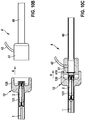
- Figures 10A through 10J show a possible procedure for implanting a sensor device 2 using the catheter device 1 in a patient.
- a lock insertion aid 12 is arranged on the shaft 10 of the catheter device 1, which is used to introduce the catheter device 1 with the coupled sensor device 2 into a lock 4, as shown in FIG Figures 10A to 10E is shown.
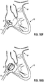
- the lock 4 serves as access to the patient and is placed in such a way that the catheter device 1 with the coupled sensor device 2 can be guided, for example, as far as the human heart H, as shown in FIG Figures 10F through 10J can be seen.
- the lock 4 is accessible from outside the patient.
- the sensor device 2 In order to insert the catheter device 1 with the coupled sensor device 2, the sensor device 2 is first of all, as shown in this Figure 10A in transition to Figure 10B can be seen, pulled into the lock insertion aid 12 on the side of an attachment piece 120, so that the bracket elements 21 of the sensor device 2 are folded in and the sensor device 2 comes to lie within a receiving shaft 121 of the lock insertion aid 12 ( Figure 10B ).
- the lock 4 has a sealing element 410 (sealing lips) through which the catheter device 1 passes when it is inserted into the lock 4 and which seals a transition to the outside.
- the lock insertion aid 12 with the sensor device 2 accommodated therein is now attached to an insertion nozzle 41 of the lock 4 with the attachment piece 120, so that an inner channel of the receiving shaft 121 of the lock insertion aid 12 is aligned with a lock shaft 40 of the lock 4 ( Figure 10C ).
- the sensor device 2 By inserting the catheter device 1 with the coupled sensor device 2 in an insertion direction A into the lock shaft 40, the sensor device 2 is now brought into the lock shaft 40 ( Figures 10D and 10E ) and can thus be guided through the lock 4 into the vessel in which the sensor device 2 is to be placed (in the example shown, the human heart H), as shown in FIG Figure 10F can be seen.
- the sensor device 2 is to be placed in the area of the pulmonary artery P.
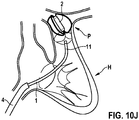
- the catheter device 1 with the distally coupled sensor device 2 is passed through the human heart H on the output side of the sheath 4 and - with the deflection of the deflectable shaft segment 11 - guided into the area of the pulmonary artery P until an intended implantation site of the sensor device 2 is reached (see FIG Figures 10G to 10J ).
- the sensor device 2 can exit the lock 4 in the right atrium ( Figure 10F ).
- the bracket elements 21 unfold, as in the transition from Figure 10F towards Figure 10G can be seen.
- the sensor device 2 can be checked (for example by means of suitable imaging methods), the sensor device 2 being able to be withdrawn if a fault or damage to the sensor device 2 is detected.
- the catheter device 1 By means of the catheter device 1, the sensor device 2 is now maneuvered into the right ventricle, for example through the tricuspid valve ( Figure 10H ), and the sensor device 2 is inserted into the pulmonary valve with the deflection of the deflectable shaft segment 11 along the anterior inner wall of the ventricle ( Figure 10I ).
- the bracket elements 21 on the sensor device 2 prevent the catheter device from sliding behind the tendon threads (chordae tendineae) of the tricuspid valve and possibly damaging them.
- the sensor device 2 is connected to the desired position in pulmonary artery P advanced ( Figure 10J ).
- the coupling device 3 can be unlocked in order to uncouple the sensor device 2.
- the sensor device 2 thus remains at its destination.
- the catheter device 1 can be withdrawn.
- the sensor device 2 can be grasped again by means of the catheter device 1 and the coupling device 3 arranged thereon in order to correct the position of the sensor device 2.
- an implanted sensor device 2 can optionally be removed from the human body again.
- a flushing line 42 is arranged on the insertion nozzle 41, which is used to flush the sheath shaft 40 when the catheter device 1 with the coupled sensor device 2 is inserted through the sheath 4.
- Fig. 11 and 12 show a further embodiment of the sensor device on the coupling device based on FIG Fig. 4 and 5 .
- a groove between the stop element 303 and the opposite portion of the housing is wider and longer than that of FIG Fig. 4 and 5 embodiment shown. Otherwise all components correspond to those already in Fig. 4 and 5 components shown and described above.
- a sensor device of the type described can have more or fewer than three bracket elements. For example, it is conceivable that the sensor device has only two bracket elements. It is also conceivable that the sensor device has more than three bracket elements, for example four or five bracket elements.
- the sensor housing can be held centrally between the bracket elements and thus centrally in a vessel.
- the bracket elements hold the sensor housing in a decentralized manner, that is to say off-center, for example approximated to a vessel wall.
- Such a sensor device can be designed as a pressure sensor, temperature sensor, oxygen sensor or flow sensor or also as another sensor and has a corresponding sensor system.
- the sensor device can function in an autarkic manner over a longer period of time in the implanted state, in order to transmit recorded sensor data, for example in the context of home monitoring, for example by means of telemetry to an external device.
Landscapes
- Health & Medical Sciences (AREA)
- Life Sciences & Earth Sciences (AREA)
- Medical Informatics (AREA)
- Biophysics (AREA)
- Pathology (AREA)
- Engineering & Computer Science (AREA)
- Biomedical Technology (AREA)
- Heart & Thoracic Surgery (AREA)
- Physics & Mathematics (AREA)
- Molecular Biology (AREA)
- Surgery (AREA)
- Animal Behavior & Ethology (AREA)
- General Health & Medical Sciences (AREA)
- Public Health (AREA)
- Veterinary Medicine (AREA)
- Cardiology (AREA)
- Vascular Medicine (AREA)
- Physiology (AREA)
- Media Introduction/Drainage Providing Device (AREA)
Abstract
Description
- Die Erfindung betrifft eine Kathetereinrichtung zum Platzieren einer Sensoreinrichtung sowie ein System mit einer Kathetereinrichtung und einer Sensoreinrichtung.
- Eine derartige Kathetereinrichtung umfasst einen Schaft und eine an dem Schaft angeordnete Kopplungseinrichtung zum Koppeln der Kathetereinrichtung mit der zumindest ein Bügelelement aufweisenden Sensoreinrichtung.
- Eine solche Kathetereinrichtung kann beispielsweise als Absetzkatheter zum Platzieren einer Sensoreinrichtung im menschlichen Herzen oder in einem anderen Blutgefäß verwendet werden. Eine Sensoreinrichtung der hier in Rede stehenden Art kann beispielsweise als Drucksensor, Temperatursensor, Sauerstoffsensor oder Flusssensor ausgebildet sein und soll innerhalb eines Patienten Messdaten aufnehmen und beispielsweise mittels Telemetrie an ein externes Gerät übertragen. Solche Sensoreinrichtungen können beispielsweise im Rahmen einer Heimüberwachung (sogenanntes Home Monitoring) von schwer kranken Patienten eingesetzt werden, um eine Überwachung und Versorgung von Patienten in einer nicht stationären Umgebung zu ermöglichen.
- Wünschenswert sind Sensoreinrichtungen, die atraumatisch, also schonend für eine Gefäßwand, in einem Patienten platzierbar sind. Das Platzieren soll hierbei einfach, flexibel und zuverlässig mittels der Kathetereinrichtung möglich sein.
- Implantierbare Sensoreinrichtungen zur Drucküberwachung im menschlichen Herzen sind beispielsweise in den Artikeln J.H. Dreyfuss et al., "Prevent the Next Heart Attack: Implant a CardioMEMS Device in a Heart Failure Patient, " M.D./alert, Feb. 2016; P. B. Adamson et al., "Champion* Trial Rational and Design: The Long-Term Safety and Clinical Efficacy of a Wireless Pulmonary Artery Pressure Monitoring System", Journal of Cardiac Failure, Vol. 17, No.1, 2011; und E. Y. Chow, "Fully Wireless Implantable Cardiovascular Pressure Monitor Integrated with a Medical Stent", IEEE Transactions on Biomedical Engineering, Vol. 57, No. 6, 2010 beschrieben.
- Aufgabe ist es, eine Kathetereinrichtung zum Platzieren einer Sensoreinrichtung sowie ein System mit einer Kathetereinrichtung und einer Sensoreinrichtung zur Verfügung zu stellen, die ein einfaches, flexibles und zuverlässiges Platzieren einer Sensoreinrichtung ermöglichen. Gegebenenfalls soll ein erneutes Greifen der Sensoreinrichtung zum Korrigieren der Sensorlage oder zum Entfernen der Sensoreinrichtung ermöglicht werden.
- Diese Aufgabe wird durch einen Gegenstand mit den Merkmalen des Anspruchs 1 gelöst.
- Demnach weist die Kopplungseinrichtung ein Kopplungselement und ein zu dem Kopplungselement verstellbares Verriegelungselement auf. Das Kopplungselement weist zumindest einen Eingriffsabschnitt auf, mit dem das zumindest eine Bügelelement der Sensoreinrichtung in Eingriff bringbar ist, wobei das Verriegelungselement ausgebildet ist, in einer gekoppelten Stellung das zumindest eine Bügelelement an dem zumindest einen Eingriffsabschnitt zu sperren, und zu dem Kopplungselement verstellbar ist, um das zumindest eine Bügelelement zum Lösen von dem zumindest einen Eingriffsabschnitt freizugeben.
- Die Kathetereinrichtung verwendet eine Kopplungseinrichtung, um eine Kopplung zu einer zu implantierenden Sensoreinrichtung herzustellen. Über die Kopplungseinrichtung kann die Sensoreinrichtung gegriffen werden, sodass in einer gekoppelten Stellung die Sensoreinrichtung fest mit der Kathetereinrichtung verbunden ist.
- Die Kopplung wird hierbei dadurch hergestellt, dass die Sensoreinrichtung in der gekoppelten Stellung mit einem oder mehreren Bügelelementen in einen oder mehrere Eingriffsabschnitte eines Kopplungselements der Kopplungseinrichtung eingreift. Die Eingriffsabschnitte können beispielsweise nach Art von Hinterschnitten geformt sein und somit eine formschlüssige Verbindung zwischen der Sensoreinrichtung und der Kopplungseinrichtung herstellen. Die formschlüssige Verbindung ist dabei über ein Verriegelungselement derart gesperrt, dass die Bügelelemente der Sensoreinrichtung in der gekoppelten Stellung nicht ohne weiteres, jedenfalls nicht ohne Betätigung des Verriegelungselements, außer Eingriff von den Eingriffsabschnitten des Kopplungselements gelangen können, sondern über die Kopplungseinrichtung zuverlässig und belastbar an der Kathetereinrichtung gehalten sind.
- In der gekoppelten Stellung kann die Sensoreinrichtung mittels der Kathetereinrichtung in einem Patienten implantiert werden und dazu an einen vorbestimmten Ort im menschlichen Herzen oder in einem anderen Gefäß gebracht werden. Ist ein Bestimmungsort erreicht, kann das Verriegelungselement betätigt werden, um die Bügelelemente der Sensoreinrichtung freizugeben und somit ein Lösen der Sensoreinrichtung von der Kopplungseinrichtung und somit von der Kathetereinrichtung zu ermöglichen.
- Das Aufheben der Kopplung kann durch Verstellen des Verrieglungselements mit vergleichsweise kleinem Hub erfolgen. Durch Verstellen des Verriegelungselements wird der zumindest eine Eingriffsabschnitt des Kopplungselements freigegeben, sodass das zumindest eine Bügelelement der Sensoreinrichtung in einfacher Weise außer Eingriff von dem Eingriffsabschnitt gebracht werden kann.
- Das Verriegelungselement dient dazu, das zumindest eine Bügelelement, wenn es in Eingriff mit dem zumindest einen Eingriffsabschnitt des Kopplungselements ist, so zu sperren, dass das zumindest eine Bügelelement nicht außer Eingriff von dem Eingriffsabschnitt gelangen kann. Das Verriegelungselement ist hierzu in einer Sperrstellung in einer derartigen räumlichen Lagebeziehung zu dem Eingriffsabschnitt, dass das Bügelelement nicht aus dem Eingriffsabschnitt entfernt werden kann. Erst wenn das Verriegelungselement zum Lösen der Kopplung betätigt ist, kann das Bügelelement aus dem zugeordneten Eingriffsabschnitt entfernt und somit die Sensoreinrichtung von der Kathetereinrichtung entkoppelt werden.
- Die Kopplungseinrichtung kann mit vergleichsweise kleinem Bauraum aufgebaut werden, was es ermöglicht, eine Kathetereinrichtung mit dünnem Schaft (Durchmesser zum Beispiel 6F oder 7F oder 1,8 mm bis 2,4 mm) zu verwenden.
- Das Kopplungselement ist, in einer Ausgestaltung, fest mit einem Abschnitt des Schafts, beispielsweise im Bereich eines distalen Endes des Schafts, verbunden. Der zumindest eine Eingriffsabschnitt ist zum Herstellen der Kopplung an dem Kopplungselement geformt derart, dass die Sensoreinrichtung über das zumindest eine Bügelelement in einfacher und zuverlässiger Weise in Eingriff mit dem Eingriffsabschnitt gebracht werden kann und in einer gekoppelten Stellung über das Verriegelungselement zu dem Kopplungselement verriegelt ist.
- Das Verriegelungselement ist, in einer Ausgestaltung, beispielsweise entlang einer Betätigungsrichtung linear zu dem Kopplungselement verstellbar. Das Kopplungselement kann zum Verriegelungselement entlang der Betätigungsrichtung geführt sein, sodass das Verriegelungselement zwischen einer Sperrstellung zum Sperren des zumindest einen Bügelelements in Eingriff mit dem zumindest einen Eingriffsabschnitt des Kopplungselements und einer Lösestellung zum Freigeben der Sensoreinrichtung verstellbar ist.
- In einer Ausgestaltung weist das Kopplungselement einen von dem Schaft abliegenden, distalen Rand auf, der sich beispielsweise entlang einer quer zur Längserstreckungsrichtung des Schafts gerichteten Ebene erstreckt und umlaufend an dem zum Beispiel hülsenförmig ausgebildeten Kopplungselement geformt ist. In den Rand ist, in einer Ausgestaltung, zumindest eine Aussparung eingeformt, an der der zumindest eine Eingriffsabschnitt nach Art eines Hinterschnitts geformt ist. Durch Eingriff in die Aussparung und den an der Aussparung geformten Eingriffsabschnitt kann ein jedes Bügelelement der Sensoreinrichtung somit mit dem Kopplungselement gekoppelt werden, wobei in der gekoppelten Stellung der Eingriff des Bügelelements in den Eingriffsabschnitt des Kopplungselements über das Verriegelungselement derart gesperrt ist, dass das Bügelelement nicht ohne weiteres - jedenfalls nicht ohne Betätigung des Verriegelungselements - außer Eingriff von dem Eingriffsabschnitt gebracht werden kann.
- In einer Ausgestaltung weist das Verriegelungselement zumindest eine Eingriffsnut zum Aufnehmen des zumindest einen Bügelelements in der gekoppelten Stellung auf Das Verriegelungselement kann beispielsweise einen in dem hülsenförmigen Kopplungselement einliegenden Körper aufweisen, der mit einer distalen Stirnseite in distaler Richtung nach außen weist. An dieser distalen Stirnseite können eine oder mehrere Eingriffsnuten geformt sein derart, dass in der gekoppelten Stellung der Sensoreinrichtung ein jedes Bügelelement der Sensoreinrichtung in eine Eingriffsnut des Verriegelungselements eingreift. Die Eingriffsnuten können sich beispielsweise radial zur (linear gerichteten) Betätigungsrichtung erstrecken und fluchten in der gekoppelten Stellung der Sensoreinrichtung derart mit dem Eingriffsabschnitt, dass ein jedes Bügelelement durch Eingriff in die Eingriffsnut zu dem jeweils zugeordneten Eingriffsabschnitt gesperrt ist und somit nicht außer Eingriff von dem Eingriffsabschnitt gebracht werden kann.
- In einer Ausgestaltung weist die Kopplungseinrichtung ein mit dem Verriegelungselement verbundenes, entlang des Schafts erstrecktes Zugelement zum Verstellen des Verrieglungselements auf. Das Zugelement dient zum Betätigen des Verriegelungselements und kann auf Zug belastet werden, um auf diese Weise das Verriegelungselement in die Betätigungsrichtung zu dem Kopplungselement zu verstellen. Das Zugelement kann sich beispielsweise von der Kopplungseinrichtung bis zu hin zu einem am proximalen Ende des Schafts angeordneten Griff erstrecken und mit einem Betätigungselement des Griffs gekoppelt sein derart, dass durch Betätigen des Betätigungselements eine Zugkraft auf das Zugelement ausgeübt und darüber das Verriegelungselement in die Betätigungsrichtung relativ zu dem Kopplungselement der Kopplungseinrichtung verstellt werden kann.
- Während die Kopplungseinrichtung zum Koppeln mit der Sensoreinrichtung am in den Körper eines Patienten einzuführenden distalen Ende des Schafts der Kathetereinrichtung angeordnet ist, ist der Griff am proximalen Ende des Schafts der Kathetereinrichtung angeordnet und somit außerhalb des Körpers des Patienten betätigbar, um nach bestimmungsgemäßer Platzierung der Sensoreinrichtung im Patienten die Kopplung zwischen der Sensoreinrichtung und der Kopplungseinrichtung aufzuheben oder, gegebenenfalls, zum Korrigieren der Lage der Sensoreinrichtung oder zum Entfernen der Sensoreinrichtung aus dem Patienten die Sensoreinrichtung erneut zu greifen. Beispielsweise kann das Betätigungselement zum Einwirken auf das Zugelement zum Verstellen des Verriegelungselements an dem Griff verdrehbar sein, wobei der Griff beispielsweise eine Verdrehsicherung aufweist, die ein unbeabsichtigtes Betätigen des Betätigungselements und somit ein unbeabsichtigtes Lösen vor bestimmungsgemäßer Platzierung der Sensoreinrichtung verhindert.
- In einer Ausgestaltung weist die Kopplungseinrichtung ein an dem Kopplungselement angeordnetes, zwischen dem Kopplungselement und dem Verriegelungselement wirkendes elastisches Element auf. Das elastische Element kann beispielsweise mit einem an dem Körper des Verriegelungselements geformten Konusabschnitt wechselwirken, derart, dass bei einem Verstellen des Verriegelungselements in die Betätigungsrichtung zum Aufheben der Kopplung der Sensoreinrichtung mit der Kopplungseinrichtung das elastische Element in elastischer Weise verformt wird und eine elastische Gegenspannung entgegen der Betätigungsrichtung auf das Verriegelungselement ausübt. Auf diese Weise kann eine selbsttätige Zurückstellung des Verriegelungselements nach erfolgter Betätigung bewirkt werden, sodass das Verriegelungselement selbsttätig in eine der Kopplungsstellung entsprechende Ausgangsstellung zurück gelangt, wenn keine Zugkräfte mehr auf das Zugelement ausgeübt werden.
- Das elastische Element kann - zusätzlich oder alternativ zum Bereitstellen einer elastischen Vorspannung - zum Abdichten eines Übergangs zwischen dem Kopplungselement und dem Schaft der Kathetereinrichtung dienen. Beispielsweise kann das elastische Element an einem Bodenabschnitt des Kopplungselements angeordnet sein, der sich quer zur Betätigungsrichtung erstreckt und einen Aufnahmeraum des Kopplungselements, in dem das Verriegelungselement in verstellbarer Weise aufgenommen ist, von dem Schaft der Kathetereinrichtung trennt. Der Bodenabschnitt kann hierbei eine Öffnung aufweisen, durch die hindurch das Zugelement zur Betätigung des Verriegelungselements geführt ist, wobei das elastische Element zum Beispiel nach Art einer Hülse derart im Bereich der Öffnung an dem Bodenabschnitt angeordnet sein kann, dass ein Übergang zwischen dem Bodenabschnitt und dem Verriegelungselement und somit die Öffnung in dem Bodenabschnitt, durch die das Zugelement hindurchgeführt ist, feuchtigkeitsdicht abgedichtet sind.
- Das Verriegelungselement ist dem Bodenabschnitt mit einer Seite zugewandt, die der die zumindest eine Eingriffsnut tragenden, distalen Stirnseite des Verriegelungselements abgewandt ist. Bei einem Betätigen des Verriegelungselements zum Aufheben der Kopplung zwischen der Sensoreinrichtung und der Kopplungseinrichtung wird das Verriegelungselement dem Bodenabschnitt angenähert, wobei das elastische Element derart zwischen dem Verriegelungselement und dem Bodenabschnitt des Kopplungselements angeordnet ist, dass das elastische Element bei einem Verstellen des Verriegelungselements in die Betätigungsrichtung elastisch verformt wird, dabei aber vorzugsweise eine feuchtigkeitsdichte Abdichtung zwischen dem Verriegelungselement und dem Bodenabschnitt aufrechterhält.
- Der Bodenabschnitt kann zudem als Anschlag für das Verriegelungselement dienen und somit einen maximalen Betätigungsweg für das Verriegelungselement definieren.
- In einer Ausgestaltung weist der Schaft ein deflektierbares Schaftsegment auf, an dem die Kopplungseinrichtung angeordnet ist. Das deflektierbare Schaftsegment ist im Bereich des distalen Endes des Schafts geformt und kann so ausgelenkt werden, dass die Kathetereinrichtung in flexibler, steuerbarer Weise auch in anatomisch gewundene Gefäße, zum Beispiel bis hin zur Pulmonalarterie, geführt werden kann, um die Sensoreinrichtung zu platzieren.
- Das deflektierbare Schaftsegment kann beispielsweise über dasselbe Betätigungselement am Griff betätigt werden, über das auch das Zugelement der Kopplungseinrichtung betätigt werden kann. Während die Betätigung des Zugelements zum Verstellen des Verriegelungselements beispielsweise durch Verdrehen des Betätigungselements am Griff erfolgen kann, kann eine Auslenkung des deflektierbaren Schaftsegments beispielsweise durch lineare Verstellung des Betätigungselements am Griff vorgenommen werden.
- Ein System umfasst eine Kathetereinrichtung nach der vorangehend beschriebenen Art und eine mit der Kopplungseinrichtung der Kathetereinrichtung zu koppelnde Sensoreinrichtung. Eine solche Sensoreinrichtung kann beispielsweise als Drucksensor, Temperatursensor, Sauerstoffsensor oder Flusssensor ausgebildet sein und umfasst beispielsweise eine eigene Energieversorgung, zum Beispiel eine Batterie, sowie eine Kommunikationseinrichtung, zum Beispiel zur Datenübertragung mittels Telemetrie, sodass die Sensoreinrichtung im menschlichen Patienten in implantiertem Zustand in autarker Weise Überwachungsaufgaben übernehmen und Datensignale an eine externe Einrichtung übermitteln kann.
- Eine solche Sensoreinrichtung umfasst beispielsweise ein Sensorgehäuse und eine oder mehrere an dem Sensorgehäuse angeordnete Bügelelemente, die in der gekoppelten Stellung mit zugeordneten Eingriffsabschnitten des Kopplungselements in Eingriff stehen und somit eine feste (aber lösbare) Verbindung zwischen der Sensoreinrichtung und der Kathetereinrichtung herstellen. Die Bügelelemente sind vorzugsweise aus einem superelastischen Material geformt und erstrecken sich derart an dem Sensorgehäuse, dass die Sensoreinrichtung in atraumatischer Weise, also gefäßwandschonend, in einem Gefäß platziert werden kann.
- Beispielsweise kann ein jedes Bügelelement mit einem ersten Ende an einer distalen Seite des Sensorgehäuses und mit einem zweiten Ende an einer der distalen Seite abgewandten, proximalen Seiten des Sensorgehäuses befestigt sein. Das Bügelelement ist somit mit beiden Enden fest mit dem Sensorgehäuse verbunden und bildet eine von dem Sensorgehäuse vorstehende Schlaufe aus. Insbesondere im Bereich des proximalen Endes des Sensorgehäuses kann die Kopplungseinrichtung an den Bügelelementen angreifen, um eine Verbindung zwischen der Sensoreinrichtung und der Kathetereinrichtung herzustellen.
- Beispielsweise kann die Sensoreinrichtung drei gleich gestaltete Bügelelemente aufweisen, die gleichverteilt um das Sensorgehäuse angeordnet sind. Das Sensorgehäuse kann hierbei in etwa mittig (betrachtet in einer Querschnittsebene senkrecht zu einer von proximal nach distal gerichteten Längserstreckungsrichtung des Sensorgehäuses) zwischen den Bügelelementen gehalten sein und über die Bügelelemente in einer implantierten Stellung derart an umliegenden Gefäßwandungen abgestützt sein, dass das Sensorgehäuse in etwa mittig in dem Gefäß gehalten wird.
- Denkbar ist jedoch auch, dass die Bügelelemente unterschiedlich gestaltet sind und das Sensorgehäuse in implantierter Stellung nicht mittig in einem Gefäß abgestützt ist, sondern beispielsweise angenähert an oder gar in Kontakt mit einer Gefäßwandung.
- Der der Erfindung zugrunde liegende Gedanke soll nachfolgend anhand der in den Figuren dargestellten Ausführungsbeispiele näher erläutert werden. Es zeigen:
- Fig. 1
- eine Ansicht eines Ausführungsbeispiels einer Kathetereinrichtung mit einer mit der Kathetereinrichtung gekoppelten Sensoreinrichtung;
- Fig. 2
- eine gesonderte Ansicht der Sensoreinrichtung;
- Fig. 3
- eine Ansicht der Sensoreinrichtung an einer Kopplungseinrichtung der Kathetereinrichtung;
- Fig. 4
- eine Ansicht der Sensoreinrichtung an der Kopplungseinrichtung, in einer gekoppelten Stellung;
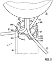
- Fig. 5
- eine Ansicht der Sensoreinrichtung an der Kopplungseinrichtung, nach Betätigen eines Verriegelungselements der Kopplungseinrichtung zum Freigeben der Sensoreinrichtung;
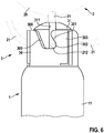
- Fig. 6
- eine Seitenansicht der Kopplungseinrichtung;
- Fig. 7
- eine Draufsicht auf die Kopplungseinrichtung;
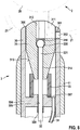
- Fig. 8
- eine Schnittansicht durch die Kopplungseinrichtung, in der gekoppelten Stellung;
- Fig. 9
- eine Schnittansicht durch die Kopplungseinrichtung, in der Freigabestellung;
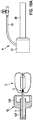
- Fig. 10A-10J
- Ansichten der Kathetereinrichtung in Zusammenwirken mit einer Schleuse zum Platzieren der Sensoreinrichtung im Gefäß eines Patienten; und
- Fig. 11 und 12
- eine weitere Ausführungsform der Sensoreinrichtung an der Kopplungseinrichtung in Anlehnung an die
Fig. 4 und5 . - Eine in
Fig. 1 dargestellte Kathetereinrichtung 1 weist einen Schaft 10 auf, der an einem proximalen Ende 100 mit einem Griff 13 verbunden ist und an einem distalen Ende 101 eine Kopplungseinrichtung 3 zur Kopplung mit einer Sensoreinrichtung 2 aufweist. Die Kathetereinrichtung 1 dient zum Implantieren der Sensoreinrichtung 2 in einem Gefäß eines Patienten, zum Beispiel im menschlichen Herzen oder in einem anderen Blutgefäß, um die beispielsweise als Drucksensor, Temperatursensor, Sauerstoffsensor oder Flusssensor ausgebildete Sensoreinrichtung 2 zu implantieren, beispielsweise zur Verwendung im Rahmen einer Heimüberwachung ("Home Monitoring") eines schwer kranken Patienten. - Die Sensoreinrichtung 2, dargestellt in einer gesonderten Ansicht in
Fig. 2 , weist ein Sensorgehäuse 20 auf, das beispielsweise eine Länge von ca. 15-20 mm und einen Durchmesser von ca. 3-5 mm aufweisen kann und elektrische und elektronische Komponenten der Sensoreinrichtung 2 einfasst. So kann die Sensoreinrichtung 2 beispielsweise eine eigene Energieversorgung, insbesondere eine Batterie, eine geeignete Sensorik, einen Prozessor sowie eine Kommunikationseinrichtung zur telemetrischen Datenübertragung aufweisen, um aufgenommene Sensorsignale vorzuverarbeiten und an externe Einrichtungen zu übertragen. - Die Sensoreinrichtung 2 ist, bei dem dargestellten Ausführungsbeispiel, als atraumatischer Sensor ausgebildet, der gefäßwandschonend in einem Patienten implantiert werden kann. Die Sensoreinrichtung 2 weist Bügelelemente 21, jeweils gefertigt aus einem superelastischen Draht, auf, die gleichverteilt um das Sensorgehäuse 20 angeordnet sind und zur Abstützung des Sensorgehäuses 20 gegenüber umliegenden Gefäßwandungen dienen, wenn die Sensoreinrichtung 2 in einen Patienten implantiert ist. Die Bügelelemente 21 sind jeweils mit einem Ende 210 mit einem distalen Ende des Sensorgehäuses 20 und mit ihrem anderen Ende 211 mit einem proximalen Ende des Sensorgehäuses 20 verbunden, wie dies aus
Fig. 2 ersichtlich ist. - Die Bügelelemente 21 können, bei dem dargestellten Ausführungsbeispiel, auch als Antennen zur Kommunikation mittels Telemetrie dienen.
- Die Kopplungseinrichtung 3 der Kathetereinrichtung 1 dient dazu, eine (lösbare) Verbindung zwischen der Kathetereinrichtung 1 und der Sensoreinrichtung 2 herzustellen, um die Sensoreinrichtung 2 unter Verwendung der Kathetereinrichtung 1 in einem Patienten zu implantieren. Wie aus
Fig. 3 und4 ersichtlich, stellt die Kopplungseinrichtung 3 in einer gekoppelten Stellung eine Verbindung zwischen der Kathetereinrichtung 1 und der Sensoreinrichtung 2 dadurch her, dass die Bügelelemente 21 der Sensoreinrichtung 2 über proximal geformte Ankerpunkte 212 an den Bügelelementen 21 (sieheFig. 2 ) an der Kopplungseinrichtung 3 gehalten sind. Die Bügelelemente 21 können bei bestehender Kopplung entfaltet sein, also sich in einem Zustand befinden, in dem sie in implantiertem Zustand in einem menschlichen Gefäß einliegen. - Der Schaft 10 weist im Bereich seines distalen Endes 101 ein deflektierbares Schaftsegment 11 auf, das ausgelenkt werden kann, um auf diese Weise die Kathetereinrichtung 1 auch durch gewundene Gefäße hindurchführen zu können. Die Kopplungseinrichtung 3 ist an dem deflektierbaren Schaftsegment 11 angeordnet, sodass bei Auslenkung des Schaftsegments 11 eine mit der Kopplungseinrichtung 3 verbundene Sensoreinrichtung 2 gemeinsam mit dem Schaftsegment 11 ausgelenkt wird.
- Die Kopplungseinrichtung 3 weist ein Kopplungselement 30 in Form einer Hülse auf, die fest mit dem Schaftsegment 11 und darüber mit dem Schaft 10 verbunden, zum Beispiel verklebt ist. Innerhalb des Kopplungselements 30 ist ein Verriegelungselement 31 aufgenommen, das zu dem Kopplungselement 30 verstellbar ist, um die Sensoreinrichtung 2 aus der gekoppelten Stellung gemäß
Fig. 4 freizugeben und somit ein Lösen der Sensoreinrichtung 2 von der Kopplungseinrichtung 3 und somit von der Kathetereinrichtung 1 zu ermöglichen, wie dies inFig. 5 dargestellt ist. - Die Kopplungseinrichtung 3 ist in unterschiedlichen Ansichten in
Fig. 6 bis 9 dargestellt. An einem von dem Schaft 10 abliegenden, distalen Rand 306 sind Aussparungen 300 in das Kopplungselement 30 eingeformt, die jeweils einen Eingriffsabschnitt 302 nach Art eines nach außen hin durch einen Sperrabschnitt 301 begrenzten Hinterschnitts ausbilden. Ist die Sensoreinrichtung 2 mit der Kopplungseinrichtung 3 gekoppelt, so liegt ein jedes Bügelelement 21 mit einem Ankerpunkt 212 in einem der Eingriffsabschnitte 302 ein und ist darüber formschlüssig an dem Kopplungselement 30 gehalten. - Der Sperrabschnitt 301 springt quer zu einer Trennrichtung E (siehe
Fig. 9 ) in den Bereich der jeweils zugeordneten Aussparung 300 vor. Der Übergang zwischen dem Sperrabschnitt 301 und dem durch den Sperrabschnitt 301 begrenzten, zurückgesetzten Eingriffsabschnitt 302 ist hierbei zur Trennrichtung E schrägt erstreckt, wie dies insbesondere auchFig. 6 ersichtlich ist. - Das Verriegelungselement 31 ist entlang einer Betätigungsrichtung Z linear innerhalb des Kopplungselements 30 verstellbar, wie dies im Übergang von
Fig. 4 hin zuFig. 5 oder vonFig. 8 hin zuFig. 9 ersichtlich ist. Das Verriegelungselement 31 ist in dem Kopplungselement 30 geführt und weist einen Körper 310 auf, an dem an einer distalen, nach außen weisenden Seite sternförmig zueinander angeordnete Eingriffsnuten 311 geformt sind, die zentral in eine Öffnung 312 münden, wie dies beispielsweise ausFig. 4 undFig. 7 ersichtlich ist. In der gekoppelten Stellung greift jedes Bügelelement 21 der Sensoreinrichtung 2 in eine der Eingriffsnuten 311 ein, wobei eine jede Eingriffsnut 311 mit einem zugeordneten Eingriffsabschnitt 302 des Kopplungselements 30 fluchtet und somit durch Eingriff des jeweiligen Bügelelements 21 in die Eingriffsnut 311 das Bügelelement 21 in dem Eingriffsabschnitt 302 gesperrt ist, wie dies zum Beispiel aus einer Zusammenschau vonFig. 4 undFig. 6 ersichtlich ist. - Im deflektierten Zustand des Katheters könnte ein Zug am Zugelement 32 erst zu einer Verstärkung der Deflektion bzw. zu einem Positionierungsfehler führen, anstatt das Verriegelungselement 31 unmittelbar zurück zu ziehen und die Sensorreinrichtung 2 frei zu geben. Dies verhindert eine Kompressionsfeder 308, da sie bei Zug am Zugelement 32 als stabilisierendes Widerlager gegen den Bodenabschnitt 304 wirkt. Das Verriegelungselement 31 wird dadurch unmittelbar ohne Positionierungsfehler zurückgezogen.
- Wird das Verriegelungselement 31 in die Betätigungsrichtung Z verstellt, so werden die Eingriffsnuten 311 aus dem Bereich der Eingriffsabschnitte 302 entfernt. Die Bügelelemente 21 gelangen dadurch, wie dies aus
Fig. 5 ersichtlich ist, außer Eingriff von den Eingriffsnuten 311, sodass die Bügelelemente 21 nicht mehr zu den Eingriffsabschnitten 302 gesperrt sind und in eine Löserichtung D (sieheFig. 7 ) durch Auflaufen auf den schrägen Übergang zwischen den Eingriffsabschnitten 302 und den Sperrabschnitten 301 außer Eingriff von den Eingriffsabschnitten 302 gebracht werden können. Die Sensoreinrichtung 2 kann somit entlang der Trennrichtung E (sieheFig. 9 ) von der Kopplungseinrichtung 3 entfernt werden, ohne dass die Bügelelemente 21 in den Aussparungen 300 verhaken können. - Das Verriegelungselement 31 ist an dem Kopplungselement 30 entlang der Betätigungsrichtung Z geführt und insbesondere in der gekoppelten Stellung (
Fig. 4 ) verdrehsicher zu dem Kopplungselement 30 abgestützt. Dazu weist das Kopplungselement 30 radial nach innen vorspringende Anschlagelemente 303 auf, die jeweils mit einem zugeordneten Anschlag 313 an der äußeren Umfangsfläche des Körpers 310 des Verriegelungselements 31 zusammenwirken derart, dass ein Verdrehen des Verriegelungselements 31 insbesondere in die Löserichtung D zu dem Kopplungselement 30 verhindert ist. - Das Verriegelungselement 31 ist mit einem Zugelement 32 verbunden, das mit einem kugelförmigen Verbindungselement 320 in der zentralen Öffnung 312 des Verriegelungselements 31 einliegt und sich mit einen Abschnitt 321 durch einen an die Öffnung 312 anschließenden, längserstreckten, verjüngten Kanal 314 des Verriegelungselements 31 hindurch erstreckt, wie dies aus
Fig. 8 und9 ersichtlich ist. Das Zugelement 32 verläuft durch eine Öffnung 305 in einem Bodenabschnitt 304 des Kopplungselements 30 hindurch und erstreckt sich entlang des Schafts 10 bis hin zu dem Griff 13 und ist aufseiten des Griffs 13 mit einem Betätigungselement 130 gekoppelt. - Das Zugelement 32 ist über das Verbindungselement 320 fest mit dem Verriegelungselement 31 verbunden. Das kugelförmige Verbindungselement 320 ist hierbei über eine Klebemasse 316 mit dem Verriegelungselement 31 verklebt und dadurch fest verbunden, wobei die Klebemasse 316 zudem eine Abdichtung des Kanals 314 distal nach außen hin bereitstellt.
- Zwischen dem Verriegelungselement 31 und dem Bodenabschnitt 304 des Kopplungselements 30 ist ein hülsenförmiges (in einem entspannten Zustand zylindrisches) elastisches Element 33 angeordnet, in das ein an dem Körper 310 des Verriegelungselements 31 geformter Konusabschnitt 315 eingreift und das elastisch vorspannend sowie dichtend zwischen dem Verriegelungselement 31 und dem Bodenabschnitt 304 des Kopplungselements 30 wirkt. Das elastische Element 33, gefertigt aus einem elastischen, zum Beispiel einem elastomeren Material, ist (vorteilhafterweise mit umfänglicher Vorspannung) an einen erhabenen Abschnitt 307 des Bodenabschnitts 304 angesetzt und umgibt die in dem Bodenabschnitt 304 geformte, das Zugelement 32 führende Öffnung 305 derart, dass die Öffnung 305 nach außen hin feuchtigkeitsdicht abgedichtet ist. Insbesondere wirkt das elastische Element 33 derart zwischen dem Verriegelungselement 31 und dem Bodenabschnitt 304, dass Feuchtigkeit nicht von außen in den Bereich des Zugelements 32 und darüber über die Öffnung 305 in das Innere des Schafts 10 gelangen kann.
- Das elastische Element 33 dient zudem zur elastischen Rückstellung des Verriegelungselements 31 nach erfolgter Betätigung. So weitet der Konusabschnitt 315 bei einem Verstellen des Verriegelungselements 31 in die Betätigungsrichtung Z das elastische Element 33 (siehe
Fig. 8 im Übergang hin zuFig. 9 ). Lassen an dem Zugelement 32 bewirkte Zugkräfte nach, bewirkt diese elastische Verformung des elastischen Elements 33 eine Rückstellkraft auf das Verriegelungselement 31 entgegen der Betätigungsrichtung Z in Richtung der inFig. 8 dargestellten Ausgangsstellung, sodass das Verriegelungselement 31 selbsttätig in die der gekoppelten Stellung zugeordnete Ausgangsstellung zurückgestellt wird. - Diese Rückstellung kann hierbei auch das Trennen der Sensoreinrichtung 2 von der Kopplungseinrichtung 3 unterstützen, indem das Verriegelungselement 31 mit seiner distalen Stirnseite auf die Bügelelemente 21 einwirkt und dadurch die Sensoreinrichtung 2 in die Trennrichtung E von der Kopplungseinrichtung 3 weg drückt.
- Am Bodenabschnitt 304 des Kopplungselements 30 mündet eine Spülleitung 34, die dazu dient, einen Innenraum des Kopplungselements 30 zu spülen. Über die Spülleitung 34 können - insbesondere in der gekoppelten Stellung der Sensoreinrichtung 2 - Zwischenräume zwischen dem Verriegelungselement 31, dem Kopplungselement 30 und den Bügelelementen 21 der Sensoreinrichtung 2 zum Beispiel mit einer Kochsalzlösung gespült und zudem auch entlüftet werden.
- Die Spülleitung 34 ist mit einem Spülanschluss 14 am Griff 13 (siehe
Fig. 1 ) verbunden, sodass eine Spülflüssigkeit über den Spülanschluss 14 hin zu der Spülleitung 34 eingeleitet werden kann. - Über das Betätigungselement 130 des Griffs 13 können, bei dem dargestellten Ausführungsbeispiel, das Verriegelungselement 31 der Kopplungseinrichtung 3 sowie das deflektierbare Schaftsegment 11 des Schafts 10 betätigt werden. Das Betätigungselement 130 kann am Griff 13 verdreht werden, um auf diese Weise eine Zugkraft auf das Zugelement 32 zu bewirken und das Verriegelungselement 31 in die Betätigungsrichtung Z zu dem Kopplungselement 30 zu verstellen. Zudem kann das Betätigungselement 130 linear an dem Griff 13 verschoben werden, um auf diese Weise, zum Beispiel über ein zugeordnetes, in dem Schaft 10 geführtes Zugseil, das Schaftsegment 11 auszulenken und somit die Kathetereinrichtung 1 durch gewundene Gefäße zu führen.
- Am Griff 13 ist, bei dem dargestellten Ausführungsbeispiel, ein Sicherungselement 131 angeordnet, das in einer Sicherungsstellung ein Verdrehen des Betätigungselements 130 und somit ein (unbeabsichtigtes) Lösen der Sensoreinrichtung 2 von der Kopplungseinrichtung 3 verhindert (ein lineares Verschieben des Betätigungselements 130 zum Betätigen des deflektierbaren Schaftsegments 11 aber zulässt). Das Sicherungselement 131 kann entfernt werden, um das Betätigungselement 130 verdrehen zu können.
-
Fig. 10A bis 10J zeigen ein mögliches Vorgehen zum Implantieren einer Sensoreinrichtung 2 unter Verwendung der Kathetereinrichtung 1 in einem Patienten. - Wie aus
Fig. 1 ersichtlich, ist am Schaft 10 der Kathetereinrichtung 1 eine Schleuseneinführhilfe 12 angeordnet, die dazu dient, die Kathetereinrichtung 1 mit der gekoppelten Sensoreinrichtung 2 in eine Schleuse 4 einzuführen, wie dies inFig. 10A bis 10E dargestellt ist. Die Schleuse 4 dient als Zugang zum Patienten und ist so gelegt, dass mittels der Schleuse 4 die Kathetereinrichtung 1 mit der gekoppelten Sensoreinrichtung 2 beispielsweise bis hin zum menschlichen Herzen H geführt werden kann, wie dies ausFig. 10F bis 10J ersichtlich ist. - Die Schleuse 4 ist von außerhalb des Patienten zugänglich. Zum Einführen der Kathetereinrichtung 1 mit der gekoppelten Sensoreinrichtung 2 wird die Sensoreinrichtung 2 zunächst, wie dies aus
Fig. 10A im Übergang hin zuFig. 10B ersichtlich ist, auf Seiten eines Ansetzstücks 120 in die Schleuseneinführhilfe 12 eingezogen, sodass die Bügelelemente 21 der Sensoreinrichtung 2 eingefaltet werden und die Sensoreinrichtung 2 innerhalb eines Aufnahmeschafts 121 der Schleuseneinführhilfe 12 zu liegen kommt (Fig. 10B ). - Am Eingang des Einführstutzens 41 weist die Schleuse 4 ein Dichtelement 410 (Dichtlippen) auf, durch das hindurch die Kathetereinrichtung 1 bei Einführen in die Schleuse 4 tritt und das einen Übergang nach außen hin abdichtet.
- Nunmehr wird die Schleuseneinführhilfe 12 mit der darin aufgenommenen Sensoreinrichtung 2 mit dem Ansetzstück 120 an einen Einführstutzen 41 der Schleuse 4 angesetzt, sodass ein innerer Kanal des Aufnahmeschafts 121 der Schleuseneinführhilfe 12 mit einem Schleusenschaft 40 der Schleuse 4 fluchtet (
Fig. 10C ). Die nach distal in runden Schlaufen gebogenen Bügelelemente 21 schieben das Dichtelement 410 des Schleusenventils schonend beiseite. Nach Durchgang der Sensoreinrichtung 2 umschließt das Dichtelement 410 die vorwärtsgeschobenen Schaftsegmente dicht. - Durch Einschieben der Kathetereinrichtung 1 mit der gekoppelten Sensoreinrichtung 2 in eine Einführrichtung A in den Schleusenschaft 40 wird nunmehr die Sensoreinrichtung 2 in den Schleusenschaft 40 verbracht (
Fig. 10D und 10E ) und kann somit durch die Schleuse 4 hindurch bis in das Gefäß, in dem die Sensoreinrichtung 2 zu platzieren ist (im beispielhaft dargestellten Fall dem menschlichen Herzen H), geführt werden, wie dies ausFig. 10F ersichtlich ist. - Im beispielhaft dargestellten Fall soll die Sensoreinrichtung 2 im Bereich der Pulmonalarterie P platziert werden. Die Kathetereinrichtung 1 mit der distal gekoppelten Sensoreinrichtung 2 wird dazu ausgangsseitig der Schleuse 4 durch das menschliche Herz H hindurchgeführt und - unter Auslenkung des deflektierbaren Schaftsegments 11 - bis in den Bereich der Pulmonalarterie P geführt, bis ein bestimmungsgemäßer Implantationsort der Sensoreinrichtung 2 erreicht ist (siehe
Fig. 10G bis Fig. 10J ). - Insbesondere kann die Sensoreinrichtung 2 im rechten Vorhof aus der Schleuse 4 austreten (
Fig. 10F ). Beim Austreten aus der Schleuse 4 entfalten sich die Bügelelemente 21, wie dies im Übergang vonFig. 10F hin zuFig. 10G ersichtlich ist. In diesem Zustand kann die Sensoreinrichtung 2 überprüft werden (beispielsweise mittels geeigneter Bildgebungsverfahren), wobei die Sensoreinrichtung 2 zurückgezogen werden kann, wenn ein Fehler oder eine Beschädigung an der Sensoreinrichtung 2 festgestellt wird. Mittels der Kathetereinrichtung 1 wird die Sensoreinrichtung 2 nunmehr beispielsweise durch die Trikuspidalklappe in den rechten Ventrikel manövriert (Fig. 10H ), und die Sensoreinrichtung 2 wird unter Auslenkung des deflektierbaren Schaftsegments 11 an der anterioren Ventrikelinnenwand entlang in die Pulmonalklappe eingeführt (Fig. 10I ). Die Bügelelemente 21 an der Sensoreinrichtung 2 verhindern, dass sich die Kathetereinrichtung hinter die Sehnenfäden (Chordae tendineae) der Trikuspidalklappe schieben und diese ggf. beschädigen. Nach Überwindung der Pulmonalklappe wird die Sensoreinrichtung 2 an die gewünschte Position in der Pulmonalarterie P vorgebracht (Fig. 10J ). Ist ein bestimmungsgemäße Ort erreicht, kann die Kopplungseinrichtung 3 entriegelt werden, um die Sensoreinrichtung 2 abzukoppeln. Die Sensoreinrichtung 2 verbleibt somit an ihrem Bestimmungsort. Die Kathetereinrichtung 1 kann zurückgezogen werden. - Wird, beispielsweise mittels Bildgebung, festgestellt, dass die Sensoreinrichtung 2 nicht korrekt platziert worden ist, so kann mittels der Kathetereinrichtung 1 und der daran angeordneten Kopplungseinrichtung 3 die Sensoreinrichtung 2 erneut gegriffen werden, um die Lage der Sensoreinrichtung 2 zu korrigieren.
- Mittels der Kathetereinrichtung 1 kann eine implantierte Sensoreinrichtung 2 ggf. wieder aus dem menschlichen Körper entfernt werden.
- Am Einführstutzen 41 ist zudem eine Spülleitung 42 angeordnet, die zum Spülen des Schleusenschafts 40 bei Einführen der Kathetereinrichtung 1 mit der gekoppelten Sensoreinrichtung 2 durch die Schleuse 4 hindurch dient.
-
Fig. 11 und12 zeigen eine weitere Ausführungsform der Sensoreinrichtung an der Kopplungseinrichtung in Anlehnung an dieFig. 4 und5 . Eine Nut zwischen dem Anschlagelement 303 und dem gegenüberliegenden Abschnitt des Gehäuses ist breiter und länger als bei der inFig. 4 und5 gezeigten Ausführungsform. Ansonsten entsprechen alle Komponenten den bereits inFig. 4 und5 dargestellten und oben beschriebenen Komponenten. - Der der Erfindung zugrunde liegende Gedanke ist nicht auf die vorangehend geschilderten Ausführungsbeispiele beschränkt, sondern lässt sich auch in anderer Weise verwirklichen.
- Eine Sensoreinrichtung der beschriebenen Art kann mehr oder weniger als drei Bügelelemente aufweisen. So ist beispielsweise denkbar, dass die Sensoreinrichtung lediglich zwei Bügelelemente aufweist. Auch ist denkbar, dass die Sensoreinrichtung mehr als drei Bügelelemente, beispielsweise vier oder fünf Bügelelemente, aufweist.
- Mittels der Bügelelemente kann das Sensorgehäuse zentral zwischen den Bügelelementen und somit zentral in einem Gefäß gehalten sein. Denkbar ist aber auch, dass die Bügelelemente das Sensorgehäuse dezentral, also außermittig, beispielsweise einer Gefäßwand angenähert, halten.
- Eine solche Sensoreinrichtung kann als Drucksensor, Temperatursensor, Sauerstoffsensor oder Flusssensor oder auch als anderer Sensor ausgebildet sein und weist eine entsprechende Sensorik auf. Die Sensoreinrichtung kann hierbei über einen längeren Zeitraum im implantierten Zustand in autarker Weise funktionieren, um erfasste Sensordaten, beispielsweise im Rahmen einer Heimüberwachung, zum Beispiel mittels Telemetrie an eine externe Einrichtung zu übertragen.
-
- 1
- Kathetereinrichtung
- 10
- Schaft
- 100
- Proximales Ende
- 101
- Distales Ende
- 11
- Abschnitt (deflektierbares Schaftsegment)
- 12
- Schleuseneinführhilfe
- 120
- Ansetzstück
- 121
- Aufnahmeschaft
- 13
- Griff
- 130
- Betätigungselement
- 131
- Sicherungselement
- 14
- Spülanschluss
- 2
- Sensoreinrichtung
- 20
- Sensorgehäuse
- 21
- Bügelelement (Drahtbügel)
- 210, 211
- Ende
- 212
- Ankerpunkt
- 3
- Kopplungseinrichtung
- 30
- Kopplungselement (Kopplungshülse)
- 300
- Aussparung
- 301
- Sperrabschnitt
- 302
- Eingriffsabschnitt
- 303
- Anschlagelement
- 304
- Bodenabschnitt
- 305
- Öffnung
- 306
- Rand
- 307
- Erhabener Abschnitt
- 308
- Kompressionswendel
- 31
- Verriegelungselement
- 310
- Körper
- 311
- Eingriffsnut
- 312
- Öffnung
- 313
- Anschlag
- 314
- Kanal
- 315
- Konusabschnitt
- 316
- Klebemasse
- 32
- Zugelement
- 320
- Verbindungselement
- 321
- Abschnitt
- 33
- Elastisches Element
- 34
- Spülleitung
- 4
- Schleuse
- 40
- Schleusenschaft
- 41
- Einführstutzen
- 410
- Dichtelement
- 42
- Spülleitung
- A
- Einführrichtung
- D
- Löserichtung
- E
- Trennrichtung
- Z
- Betätigungsrichtung
Claims (15)
- Kathetereinrichtung (1) zum Platzieren einer Sensoreinrichtung (2), mit einem Schaft (10) und einer an dem Schaft (10) angeordneten Kopplungseinrichtung (3) zum Koppeln der Kathetereinrichtung (1) mit der zumindest ein Bügelelement (21) aufweisenden Sensoreinrichtung (2), wobei die Kopplungseinrichtung (3) ein Kopplungselement (30) und ein zu dem Kopplungselement (30) verstellbares Verriegelungselement (31) aufweist, wobei das Kopplungselement (30) zumindest einen Eingriffsabschnitt (302) aufweist, mit dem das zumindest eine Bügelelement (21) der Sensoreinrichtung (2) in Eingriff bringbar ist, wobei das Verriegelungselement (31) ausgebildet ist, in einer gekoppelten Stellung das zumindest eine Bügelelement (21) an dem zumindest einen Eingriffsabschnitt (302) zu sperren, und zu dem Kopplungselement (30) verstellbar ist, um das zumindest eine Bügelelement (21) zum Lösen von dem zumindest einen Eingriffsabschnitt (302) freizugeben.
- Kathetereinrichtung (1) nach Anspruch 1, wobei das Kopplungselement (30) fest mit einem Abschnitt (11) des Schafts (10) verbunden ist.
- Kathetereinrichtung (1) nach Anspruch 1 oder 2, wobei das Verriegelungselement (31) entlang einer Betätigungsrichtung (Z) linear zu dem Kopplungselement (30) verstellbar ist.
- Kathetereinrichtung (1) nach Anspruch 3, wobei das Kopplungselement (30) als Hülse ausgebildet ist, in der das Verriegelungselement (30) entlang der Betätigungsrichtung (Z) geführt ist.
- Kathetereinrichtung (1) nach einem der vorangehenden Ansprüche, wobei das Kopplungselement (30) an einem von dem Schaft (10) abliegenden Rand (306) zumindest eine Aussparung (300) aufweist, an der der zumindest eine Eingriffsabschnitt (302) geformt ist.
- Kathetereinrichtung (1) nach einem der vorangehenden Ansprüche, wobei das Verriegelungselement (31) zumindest eine Eingriffsnut (302) zum Aufnehmen des zumindest einen Bügelelements (21) in der gekoppelten Stellung aufweist.
- Kathetereinrichtung (1) nach einem der vorangehenden Ansprüche, wobei die Kopplungseinrichtung (3) ein mit dem Verriegelungselement (31) verbundenes, entlang des Schafts (10) erstrecktes Zugelement (32) zum Verstellen des Verriegelungselements (31) aufweist.
- Kathetereinrichtung (1) nach Anspruch 7, ferner aufweisend einen Griff (13), der an einem der Kopplungseinrichtung (3) abgewandten Ende des Schafts (10) angeordnet ist, wobei der Griff (13) ein Betätigungselement (130) zum Betätigen des Zugelements (32) aufweist.
- Kathetereinrichtung (1) nach einem der vorangehenden Ansprüche, wobei die Kopplungseinrichtung (3) ein an dem Kopplungselement (30) angeordnetes, zwischen dem Kopplungselement (30) und dem Verriegelungselement (31) wirkendes, elastisches Element (33) aufweist.
- Kathetereinrichtung (1) nach Anspruch 9, wobei das Verriegelungselement (31) einen Körper (310) und einen an dem Körper (310) geformten Konusabschnitt (315) zum Wechselwirken mit dem elastischen Element (33) aufweist.
- Kathetereinrichtung (1) nach Anspruch 9 oder 10, wobei das Kopplungselement (30) einen Bodenabschnitt (304) aufweist, an dem das elastische Element (33) angeordnet ist und dem das Verriegelungselement (31) bei einem Verstellen zum Lösen des zumindest einen Bügelelements (21) von dem zumindest einen Eingriffsabschnitt (302) angenähert wird.
- Kathetereinrichtung (1) nach einem der vorangehenden Ansprüche, wobei der Schaft (10) ein deflektierbares Schaftsegment (11) aufweist, an dem die Kopplungseinrichtung (3) angeordnet ist.
- System mit einer Kathetereinrichtung (1) nach einem der vorangehenden Ansprüche und einer mit der Kopplungseinrichtung (3) der Kathetereinrichtung (1) zu koppelnden Sensoreinrichtung (2).
- System nach Anspruch 13, wobei die Sensoreinrichtung (2) ein Sensorgehäuse (20) und zumindest ein an dem Sensorgehäuse (20) angeordnetes Bügelelement (21) aufweist, das in der gekoppelten Stellung mit dem zumindest einen Eingriffsabschnitt (302) des Kopplungselements (30) in Eingriff steht.
- System nach Anspruch 14, wobei das zumindest eine Bügelelement (21) mit einem ersten Ende (210) an einer distalen Seite des Sensorgehäuses (20) und mit einem zweiten Ende (211) mit einem der distalen Seite abgewandten, proximalen Seite des Sensorgehäuses (20) verbunden ist.
Priority Applications (3)
| Application Number | Priority Date | Filing Date | Title |
|---|---|---|---|
| EP19179895.8A EP3750472B1 (de) | 2019-06-13 | 2019-06-13 | Kathetereinrichtung zum platzieren eines sensors |
| US16/946,149 US11759112B2 (en) | 2019-06-13 | 2020-06-08 | Catheter device for placing a sensor |
| SG10202005540VA SG10202005540VA (en) | 2019-06-13 | 2020-06-11 | Catheter device for placing a sensor |
Applications Claiming Priority (1)
| Application Number | Priority Date | Filing Date | Title |
|---|---|---|---|
| EP19179895.8A EP3750472B1 (de) | 2019-06-13 | 2019-06-13 | Kathetereinrichtung zum platzieren eines sensors |
Publications (2)
| Publication Number | Publication Date |
|---|---|
| EP3750472A1 true EP3750472A1 (de) | 2020-12-16 |
| EP3750472B1 EP3750472B1 (de) | 2023-04-19 |
Family
ID=67003189
Family Applications (1)
| Application Number | Title | Priority Date | Filing Date |
|---|---|---|---|
| EP19179895.8A Active EP3750472B1 (de) | 2019-06-13 | 2019-06-13 | Kathetereinrichtung zum platzieren eines sensors |
Country Status (3)
| Country | Link |
|---|---|
| US (1) | US11759112B2 (de) |
| EP (1) | EP3750472B1 (de) |
| SG (1) | SG10202005540VA (de) |
Families Citing this family (1)
| Publication number | Priority date | Publication date | Assignee | Title |
|---|---|---|---|---|
| CN218684859U (zh) * | 2021-05-21 | 2023-03-24 | 爱德华兹生命科学公司 | 传感器植入装置 |
Citations (3)
| Publication number | Priority date | Publication date | Assignee | Title |
|---|---|---|---|---|
| US20120108986A1 (en) * | 2010-10-29 | 2012-05-03 | Medtronic Vascular, Inc. | Implantable Medical Sensor and Fixation System |
| US20150273212A1 (en) * | 2014-04-01 | 2015-10-01 | Medtronic, Inc. | Interventional medical systems, tools, and associated methods |
| US20160279423A1 (en) * | 2015-03-27 | 2016-09-29 | Medtronic, Inc. | Medical device delivery system |
Family Cites Families (1)
| Publication number | Priority date | Publication date | Assignee | Title |
|---|---|---|---|---|
| US11344210B2 (en) * | 2016-12-20 | 2022-05-31 | Medtronic, Inc. | Delivery catheter for implantable medical device |
-
2019
- 2019-06-13 EP EP19179895.8A patent/EP3750472B1/de active Active
-
2020
- 2020-06-08 US US16/946,149 patent/US11759112B2/en active Active
- 2020-06-11 SG SG10202005540VA patent/SG10202005540VA/en unknown
Patent Citations (3)
| Publication number | Priority date | Publication date | Assignee | Title |
|---|---|---|---|---|
| US20120108986A1 (en) * | 2010-10-29 | 2012-05-03 | Medtronic Vascular, Inc. | Implantable Medical Sensor and Fixation System |
| US20150273212A1 (en) * | 2014-04-01 | 2015-10-01 | Medtronic, Inc. | Interventional medical systems, tools, and associated methods |
| US20160279423A1 (en) * | 2015-03-27 | 2016-09-29 | Medtronic, Inc. | Medical device delivery system |
Non-Patent Citations (3)
| Title |
|---|
| E. Y. CHOW: "Fully Wireless Implantable Cardiovascular Pressure Monitor Integrated with a Medical Stent", IEEE TRANSACTIONS ON BIOMEDICAL ENGINEERING, vol. 57, no. 6, 2010, XP011343270, DOI: doi:10.1109/TBME.2010.2041058 |
| J.H. DREYFUSS ET AL.: "Prevent the Next Heart Attack: Implant a CardioMEMS Device in a Heart Failure Patient", M.D./ALERT, February 2016 (2016-02-01) |
| P. B. ADAMSON ET AL.: "Champion* Trial Rational and Design: The Long-Term Safety and Clinical Efficacy of a Wireless Pulmonary Artery Pressure Monitoring System", JOURNAL OF CARDIAC FAILURE, vol. 17, no. l, 2011 |
Also Published As
| Publication number | Publication date |
|---|---|
| EP3750472B1 (de) | 2023-04-19 |
| US20200390341A1 (en) | 2020-12-17 |
| US11759112B2 (en) | 2023-09-19 |
| SG10202005540VA (en) | 2021-01-28 |
Similar Documents
| Publication | Publication Date | Title |
|---|---|---|
| US12128237B2 (en) | System and method for loading a leadless pacemaker onto a catheter-based delivery system | |
| US11478637B2 (en) | Intracardiac capsule and an implantation accessory for use with the femoral artery | |
| US12186551B2 (en) | Coupling system between a medical device and its implantation accessory | |
| DE112019002229T5 (de) | Vorrichtungen und Verfahren zum Falten prothetischer Implantate | |
| EP3285865B1 (de) | Interventionelle medizinische systeme und zugehörige fixierungsanordnung und verfahren | |
| EP3843833B1 (de) | Einführsystem zum implantieren einer medizinischen vorrichtung | |
| EP2427150B1 (de) | Vorrichtung zum freisetzen eines selbstexpandierbaren medizinischen funktionselements | |
| EP2710985A2 (de) | Implantat, System aus einem Implantat und einem Katheter sowie Verfahren zur Herstellung eines solchen Systems | |
| EP2123323B1 (de) | Implantierbare Elektrodenleitung | |
| US20120296417A1 (en) | Corkscrew Annuloplasty Device | |
| US20170340877A1 (en) | Torque limiting mechanism between a medical device and its implantation accessory | |
| US20110144735A1 (en) | Introducer | |
| EP4101397B1 (de) | Okkludereinführsystem und einführeinheit | |
| DE19908851A1 (de) | Marknagel zur Knochendistraktion | |
| EP1759632A1 (de) | Implantierbare Vorrichtung zur Messung biometrischer Parameter des Blutes | |
| DE102011011178A1 (de) | Abgabevorrichtung für ein implantierbares Kontrollgerät | |
| EP3463565B1 (de) | Momentbegrenzender mechanismus zwischen einer medizinischen vorrichtung und seinem implantationszubehör | |
| EP3750472B1 (de) | Kathetereinrichtung zum platzieren eines sensors | |
| EP2987526A1 (de) | Medizinisches implantat mit einer fixiervorrichtung | |
| AU2021400419A1 (en) | Modular pre-loaded medical implants and delivery systems | |
| WO2013167655A1 (de) | Verstärkungsimplantat für einen langgestreckten knochen, insbesondere femur | |
| US20230000476A1 (en) | Implantable closure device to seal punctures of spinal cord and brain meninges membranes and prevent leakage of cerebrospinal fluid | |
| EP4074364B1 (de) | Medizinischer tubus und verbindungsvorrichtung einer medizinischen vorrichtung | |
| DE102017115114A1 (de) | Implantatfreisetzungseinrichtung | |
| CN121772957A (zh) | 用于医疗装置的递送和取回系统 |
Legal Events
| Date | Code | Title | Description |
|---|---|---|---|
| PUAI | Public reference made under article 153(3) epc to a published international application that has entered the european phase |
Free format text: ORIGINAL CODE: 0009012 |
|
| STAA | Information on the status of an ep patent application or granted ep patent |
Free format text: STATUS: THE APPLICATION HAS BEEN PUBLISHED |
|
| AK | Designated contracting states |
Kind code of ref document: A1 Designated state(s): AL AT BE BG CH CY CZ DE DK EE ES FI FR GB GR HR HU IE IS IT LI LT LU LV MC MK MT NL NO PL PT RO RS SE SI SK SM TR |
|
| AX | Request for extension of the european patent |
Extension state: BA ME |
|
| STAA | Information on the status of an ep patent application or granted ep patent |
Free format text: STATUS: REQUEST FOR EXAMINATION WAS MADE |
|
| 17P | Request for examination filed |
Effective date: 20210616 |
|
| RBV | Designated contracting states (corrected) |
Designated state(s): AL AT BE BG CH CY CZ DE DK EE ES FI FR GB GR HR HU IE IS IT LI LT LU LV MC MK MT NL NO PL PT RO RS SE SI SK SM TR |
|
| GRAP | Despatch of communication of intention to grant a patent |
Free format text: ORIGINAL CODE: EPIDOSNIGR1 |
|
| STAA | Information on the status of an ep patent application or granted ep patent |
Free format text: STATUS: GRANT OF PATENT IS INTENDED |
|
| RIC1 | Information provided on ipc code assigned before grant |
Ipc: A61M 25/00 20060101ALI20221209BHEP Ipc: A61B 5/00 20060101AFI20221209BHEP |
|
| INTG | Intention to grant announced |
Effective date: 20230104 |
|
| GRAS | Grant fee paid |
Free format text: ORIGINAL CODE: EPIDOSNIGR3 |
|
| GRAA | (expected) grant |
Free format text: ORIGINAL CODE: 0009210 |
|
| STAA | Information on the status of an ep patent application or granted ep patent |
Free format text: STATUS: THE PATENT HAS BEEN GRANTED |
|
| AK | Designated contracting states |
Kind code of ref document: B1 Designated state(s): AL AT BE BG CH CY CZ DE DK EE ES FI FR GB GR HR HU IE IS IT LI LT LU LV MC MK MT NL NO PL PT RO RS SE SI SK SM TR |
|
| REG | Reference to a national code |
Ref country code: GB Ref legal event code: FG4D Free format text: NOT ENGLISH |
|
| REG | Reference to a national code |
Ref country code: DE Ref legal event code: R096 Ref document number: 502019007474 Country of ref document: DE |
|
| REG | Reference to a national code |
Ref country code: CH Ref legal event code: EP |
|
| REG | Reference to a national code |
Ref country code: IE Ref legal event code: FG4D Free format text: LANGUAGE OF EP DOCUMENT: GERMAN |
|
| REG | Reference to a national code |
Ref country code: AT Ref legal event code: REF Ref document number: 1560610 Country of ref document: AT Kind code of ref document: T Effective date: 20230515 |
|
| P01 | Opt-out of the competence of the unified patent court (upc) registered |
Effective date: 20230612 |
|
| REG | Reference to a national code |
Ref country code: LT Ref legal event code: MG9D |
|
| REG | Reference to a national code |
Ref country code: NL Ref legal event code: MP Effective date: 20230419 |
|
| PG25 | Lapsed in a contracting state [announced via postgrant information from national office to epo] |
Ref country code: NL Free format text: LAPSE BECAUSE OF FAILURE TO SUBMIT A TRANSLATION OF THE DESCRIPTION OR TO PAY THE FEE WITHIN THE PRESCRIBED TIME-LIMIT Effective date: 20230419 |
|
| PG25 | Lapsed in a contracting state [announced via postgrant information from national office to epo] |
Ref country code: SE Free format text: LAPSE BECAUSE OF FAILURE TO SUBMIT A TRANSLATION OF THE DESCRIPTION OR TO PAY THE FEE WITHIN THE PRESCRIBED TIME-LIMIT Effective date: 20230419 Ref country code: PT Free format text: LAPSE BECAUSE OF FAILURE TO SUBMIT A TRANSLATION OF THE DESCRIPTION OR TO PAY THE FEE WITHIN THE PRESCRIBED TIME-LIMIT Effective date: 20230821 Ref country code: NO Free format text: LAPSE BECAUSE OF FAILURE TO SUBMIT A TRANSLATION OF THE DESCRIPTION OR TO PAY THE FEE WITHIN THE PRESCRIBED TIME-LIMIT Effective date: 20230719 Ref country code: ES Free format text: LAPSE BECAUSE OF FAILURE TO SUBMIT A TRANSLATION OF THE DESCRIPTION OR TO PAY THE FEE WITHIN THE PRESCRIBED TIME-LIMIT Effective date: 20230419 |
|
| PG25 | Lapsed in a contracting state [announced via postgrant information from national office to epo] |
Ref country code: RS Free format text: LAPSE BECAUSE OF FAILURE TO SUBMIT A TRANSLATION OF THE DESCRIPTION OR TO PAY THE FEE WITHIN THE PRESCRIBED TIME-LIMIT Effective date: 20230419 Ref country code: PL Free format text: LAPSE BECAUSE OF FAILURE TO SUBMIT A TRANSLATION OF THE DESCRIPTION OR TO PAY THE FEE WITHIN THE PRESCRIBED TIME-LIMIT Effective date: 20230419 Ref country code: LV Free format text: LAPSE BECAUSE OF FAILURE TO SUBMIT A TRANSLATION OF THE DESCRIPTION OR TO PAY THE FEE WITHIN THE PRESCRIBED TIME-LIMIT Effective date: 20230419 Ref country code: LT Free format text: LAPSE BECAUSE OF FAILURE TO SUBMIT A TRANSLATION OF THE DESCRIPTION OR TO PAY THE FEE WITHIN THE PRESCRIBED TIME-LIMIT Effective date: 20230419 Ref country code: IS Free format text: LAPSE BECAUSE OF FAILURE TO SUBMIT A TRANSLATION OF THE DESCRIPTION OR TO PAY THE FEE WITHIN THE PRESCRIBED TIME-LIMIT Effective date: 20230819 Ref country code: HR Free format text: LAPSE BECAUSE OF FAILURE TO SUBMIT A TRANSLATION OF THE DESCRIPTION OR TO PAY THE FEE WITHIN THE PRESCRIBED TIME-LIMIT Effective date: 20230419 Ref country code: GR Free format text: LAPSE BECAUSE OF FAILURE TO SUBMIT A TRANSLATION OF THE DESCRIPTION OR TO PAY THE FEE WITHIN THE PRESCRIBED TIME-LIMIT Effective date: 20230720 Ref country code: AL Free format text: LAPSE BECAUSE OF FAILURE TO SUBMIT A TRANSLATION OF THE DESCRIPTION OR TO PAY THE FEE WITHIN THE PRESCRIBED TIME-LIMIT Effective date: 20230419 |
|
| PG25 | Lapsed in a contracting state [announced via postgrant information from national office to epo] |
Ref country code: FI Free format text: LAPSE BECAUSE OF FAILURE TO SUBMIT A TRANSLATION OF THE DESCRIPTION OR TO PAY THE FEE WITHIN THE PRESCRIBED TIME-LIMIT Effective date: 20230419 |
|
| REG | Reference to a national code |
Ref country code: DE Ref legal event code: R119 Ref document number: 502019007474 Country of ref document: DE |
|
| PG25 | Lapsed in a contracting state [announced via postgrant information from national office to epo] |
Ref country code: SK Free format text: LAPSE BECAUSE OF FAILURE TO SUBMIT A TRANSLATION OF THE DESCRIPTION OR TO PAY THE FEE WITHIN THE PRESCRIBED TIME-LIMIT Effective date: 20230419 |
|
| PG25 | Lapsed in a contracting state [announced via postgrant information from national office to epo] |
Ref country code: MC Free format text: LAPSE BECAUSE OF FAILURE TO SUBMIT A TRANSLATION OF THE DESCRIPTION OR TO PAY THE FEE WITHIN THE PRESCRIBED TIME-LIMIT Effective date: 20230419 |
|
| PG25 | Lapsed in a contracting state [announced via postgrant information from national office to epo] |
Ref country code: SM Free format text: LAPSE BECAUSE OF FAILURE TO SUBMIT A TRANSLATION OF THE DESCRIPTION OR TO PAY THE FEE WITHIN THE PRESCRIBED TIME-LIMIT Effective date: 20230419 Ref country code: SK Free format text: LAPSE BECAUSE OF FAILURE TO SUBMIT A TRANSLATION OF THE DESCRIPTION OR TO PAY THE FEE WITHIN THE PRESCRIBED TIME-LIMIT Effective date: 20230419 Ref country code: RO Free format text: LAPSE BECAUSE OF FAILURE TO SUBMIT A TRANSLATION OF THE DESCRIPTION OR TO PAY THE FEE WITHIN THE PRESCRIBED TIME-LIMIT Effective date: 20230419 Ref country code: MC Free format text: LAPSE BECAUSE OF FAILURE TO SUBMIT A TRANSLATION OF THE DESCRIPTION OR TO PAY THE FEE WITHIN THE PRESCRIBED TIME-LIMIT Effective date: 20230419 Ref country code: EE Free format text: LAPSE BECAUSE OF FAILURE TO SUBMIT A TRANSLATION OF THE DESCRIPTION OR TO PAY THE FEE WITHIN THE PRESCRIBED TIME-LIMIT Effective date: 20230419 Ref country code: DK Free format text: LAPSE BECAUSE OF FAILURE TO SUBMIT A TRANSLATION OF THE DESCRIPTION OR TO PAY THE FEE WITHIN THE PRESCRIBED TIME-LIMIT Effective date: 20230419 Ref country code: CZ Free format text: LAPSE BECAUSE OF FAILURE TO SUBMIT A TRANSLATION OF THE DESCRIPTION OR TO PAY THE FEE WITHIN THE PRESCRIBED TIME-LIMIT Effective date: 20230419 |
|
| PLBE | No opposition filed within time limit |
Free format text: ORIGINAL CODE: 0009261 |
|
| STAA | Information on the status of an ep patent application or granted ep patent |
Free format text: STATUS: NO OPPOSITION FILED WITHIN TIME LIMIT |
|
| REG | Reference to a national code |
Ref country code: BE Ref legal event code: MM Effective date: 20230630 |
|
| PG25 | Lapsed in a contracting state [announced via postgrant information from national office to epo] |
Ref country code: LU Free format text: LAPSE BECAUSE OF NON-PAYMENT OF DUE FEES Effective date: 20230613 |
|
| 26N | No opposition filed |
Effective date: 20240122 |
|
| GBPC | Gb: european patent ceased through non-payment of renewal fee |
Effective date: 20230719 |
|
| PG25 | Lapsed in a contracting state [announced via postgrant information from national office to epo] |
Ref country code: LU Free format text: LAPSE BECAUSE OF NON-PAYMENT OF DUE FEES Effective date: 20230613 |
|
| PG25 | Lapsed in a contracting state [announced via postgrant information from national office to epo] |
Ref country code: DE Free format text: LAPSE BECAUSE OF NON-PAYMENT OF DUE FEES Effective date: 20240103 Ref country code: GB Free format text: LAPSE BECAUSE OF NON-PAYMENT OF DUE FEES Effective date: 20230719 |
|
| PG25 | Lapsed in a contracting state [announced via postgrant information from national office to epo] |
Ref country code: SI Free format text: LAPSE BECAUSE OF FAILURE TO SUBMIT A TRANSLATION OF THE DESCRIPTION OR TO PAY THE FEE WITHIN THE PRESCRIBED TIME-LIMIT Effective date: 20230419 |
|
| PG25 | Lapsed in a contracting state [announced via postgrant information from national office to epo] |
Ref country code: SI Free format text: LAPSE BECAUSE OF FAILURE TO SUBMIT A TRANSLATION OF THE DESCRIPTION OR TO PAY THE FEE WITHIN THE PRESCRIBED TIME-LIMIT Effective date: 20230419 Ref country code: IT Free format text: LAPSE BECAUSE OF FAILURE TO SUBMIT A TRANSLATION OF THE DESCRIPTION OR TO PAY THE FEE WITHIN THE PRESCRIBED TIME-LIMIT Effective date: 20230419 Ref country code: FR Free format text: LAPSE BECAUSE OF NON-PAYMENT OF DUE FEES Effective date: 20230619 Ref country code: BE Free format text: LAPSE BECAUSE OF NON-PAYMENT OF DUE FEES Effective date: 20230630 |
|
| PGFP | Annual fee paid to national office [announced via postgrant information from national office to epo] |
Ref country code: IE Payment date: 20240617 Year of fee payment: 6 |
|
| PGFP | Annual fee paid to national office [announced via postgrant information from national office to epo] |
Ref country code: CH Payment date: 20240701 Year of fee payment: 6 |
|
| PG25 | Lapsed in a contracting state [announced via postgrant information from national office to epo] |
Ref country code: BG Free format text: LAPSE BECAUSE OF FAILURE TO SUBMIT A TRANSLATION OF THE DESCRIPTION OR TO PAY THE FEE WITHIN THE PRESCRIBED TIME-LIMIT Effective date: 20230419 |
|
| PG25 | Lapsed in a contracting state [announced via postgrant information from national office to epo] |
Ref country code: BG Free format text: LAPSE BECAUSE OF FAILURE TO SUBMIT A TRANSLATION OF THE DESCRIPTION OR TO PAY THE FEE WITHIN THE PRESCRIBED TIME-LIMIT Effective date: 20230419 |
|
| PG25 | Lapsed in a contracting state [announced via postgrant information from national office to epo] |
Ref country code: CY Free format text: LAPSE BECAUSE OF FAILURE TO SUBMIT A TRANSLATION OF THE DESCRIPTION OR TO PAY THE FEE WITHIN THE PRESCRIBED TIME-LIMIT; INVALID AB INITIO Effective date: 20190613 |
|
| REG | Reference to a national code |
Ref country code: AT Ref legal event code: MM01 Ref document number: 1560610 Country of ref document: AT Kind code of ref document: T Effective date: 20240613 |
|
| PG25 | Lapsed in a contracting state [announced via postgrant information from national office to epo] |
Ref country code: HU Free format text: LAPSE BECAUSE OF FAILURE TO SUBMIT A TRANSLATION OF THE DESCRIPTION OR TO PAY THE FEE WITHIN THE PRESCRIBED TIME-LIMIT; INVALID AB INITIO Effective date: 20190613 |
|
| PG25 | Lapsed in a contracting state [announced via postgrant information from national office to epo] |
Ref country code: AT Free format text: LAPSE BECAUSE OF NON-PAYMENT OF DUE FEES Effective date: 20240613 |
|
| PG25 | Lapsed in a contracting state [announced via postgrant information from national office to epo] |
Ref country code: TR Free format text: LAPSE BECAUSE OF FAILURE TO SUBMIT A TRANSLATION OF THE DESCRIPTION OR TO PAY THE FEE WITHIN THE PRESCRIBED TIME-LIMIT Effective date: 20230419 |
|
| REG | Reference to a national code |
Ref country code: CH Ref legal event code: H13 Free format text: ST27 STATUS EVENT CODE: U-0-0-H10-H13 (AS PROVIDED BY THE NATIONAL OFFICE) Effective date: 20260127 |
|
| PG25 | Lapsed in a contracting state [announced via postgrant information from national office to epo] |
Ref country code: IE Free format text: LAPSE BECAUSE OF NON-PAYMENT OF DUE FEES Effective date: 20250613 |
|
| PGFP | Annual fee paid to national office [announced via postgrant information from national office to epo] |
Ref country code: AT Payment date: 20260410 Year of fee payment: 5 |
|
| PG25 | Lapsed in a contracting state [announced via postgrant information from national office to epo] |
Ref country code: CH Free format text: LAPSE BECAUSE OF NON-PAYMENT OF DUE FEES Effective date: 20250630 |