EP3750396A1 - Plunger scraper for reciprocating baler - Google Patents
Plunger scraper for reciprocating baler Download PDFInfo
- Publication number
- EP3750396A1 EP3750396A1 EP20178173.9A EP20178173A EP3750396A1 EP 3750396 A1 EP3750396 A1 EP 3750396A1 EP 20178173 A EP20178173 A EP 20178173A EP 3750396 A1 EP3750396 A1 EP 3750396A1
- Authority
- EP
- European Patent Office
- Prior art keywords
- annular
- projection
- mounting plate
- plate
- aperture
- Prior art date
- Legal status (The legal status is an assumption and is not a legal conclusion. Google has not performed a legal analysis and makes no representation as to the accuracy of the status listed.)
- Granted
Links
Images




Classifications
-
- A—HUMAN NECESSITIES
- A01—AGRICULTURE; FORESTRY; ANIMAL HUSBANDRY; HUNTING; TRAPPING; FISHING
- A01F—PROCESSING OF HARVESTED PRODUCE; HAY OR STRAW PRESSES; DEVICES FOR STORING AGRICULTURAL OR HORTICULTURAL PRODUCE
- A01F15/00—Baling presses for straw, hay or the like
- A01F15/04—Plunger presses
- A01F15/042—Plungers
-
- B—PERFORMING OPERATIONS; TRANSPORTING
- B30—PRESSES
- B30B—PRESSES IN GENERAL
- B30B9/00—Presses specially adapted for particular purposes
- B30B9/30—Presses specially adapted for particular purposes for baling; Compression boxes therefor
- B30B9/3003—Details
- B30B9/3021—Press rams
Definitions
- the disclosure generally relates to a scraper assembly for a baler, and more specifically, to a scraper assembly for a baler having a reciprocating plunger moveable within a compression chamber.
- Agricultural balers gather, compress, and shape crop material into a bale.
- balers which create rectangular or square bales, or cylindrical or round bales.
- One exemplary baler is often referred to as a large square baler.
- Large square balers have been used in crop harvesting for many years, and utilize a compression system including a gearbox with a crank arm and connecting rod which are attached to a reciprocating plunger. During each rotation of the crank arm, the reciprocating plunger compresses the crop in a baling or compression chamber as the plunger moves towards the rear of the baler.
- the crop material may extrude past a face of the reciprocating plunger, between a side of the reciprocating plunger and the walls of the compression chamber.
- Scraping assemblies may be attached to the face of the reciprocating plunger to prevent or limit crop material from extruding past the face of the reciprocating plunger and becoming lodged between the walls of the compression chamber and the reciprocating plunger.
- a scraper assembly for a baler having a reciprocating plunger moveable within a compression chamber includes a mounting plate that is configured for attachment to a face of the plunger.
- the mounting plate includes an annular countersunk region.
- a follower plate includes an annular aperture.
- a scraper plate is attached to the follower plate.
- the scraper plate is configured for scraping a wall of the compression chamber.
- a cam insert includes an eccentric connection interconnecting the annular aperture of the follower plate and the annular countersunk region of the mounting plate. Rotation of the cam insert moves the follower plate relative to the mounting plate for adjusting the follower plate relative to a wall of the compression chamber.
- the cam insert includes a first annular projection seated within the annular aperture of the follower plate, and a second annular projection seated within the annular countersunk region of the mounting plate.
- the cam insert further includes a through bore extending through the second annular projection.
- a fastener extends through the through bore of the cam insert. The fastener is disposed in interlocking engagement with the mounting plate for securing the follower plate relative to the mounting plate.
- the second annular projection and the through bore are eccentrically located relative to the first annular projection.
- the mounting plate includes a mounting bore concentric with the annular countersunk region.
- the mounting bore includes internal threads and the fastener includes external threads in threaded engagement with the internal threads of the mounting bore.
- the through bore includes an internal diameter
- the fastener includes a shank portion having a shank diameter.
- the internal diameter of the through bore is larger than the shank diameter to limit shear transfer between the cam insert and the shank portion of the fastener.
- the follower plate and the scraper plate are arranged substantially perpendicular relative to each other.
- the follower plate and the scraper plate may be integrally formed together from a single structure, or may be permanently attached together, such as by welding or some other similar process.
- the annular aperture includes an aperture diameter
- the first annular projection includes a first projection diameter.
- the aperture diameter is larger than the first projection diameter to enable relative movement between the first annular projection and the annular aperture, in a direction perpendicular to a central axis of the annular countersunk region.
- the aperture diameter is between 0.1 mm and 1.0 mm larger than the first projection diameter.
- the annular countersunk region includes a countersunk diameter
- the second projection includes a second projection diameter.
- the countersunk diameter is larger than the second projection diameter to enable relative movement between the second annular projection and the annular countersunk region, in a direction perpendicular to a central axis of the annular countersunk region.
- the countersunk diameter is between 0.1 mm and 1.0 mm larger than the second projection diameter.
- the cam insert includes a base portion having an inner surface disposed against an exterior surface of the follower plate.
- the first projection extends away from the inner surface a first distance
- the second projection extends away from the inner surface a second distance. The second distance is greater than the first distance.
- the base portion includes an exterior edge forming a cross sectional shape perpendicular to the central axis of the annular countersunk region.
- the cross-sectional shape of the base portion includes a base area, and the annular aperture includes an aperture area.
- the base area is larger than the aperture area.
- the cross-sectional shape of the base portion is a hexagon.
- the mounting plate includes a second annular countersunk region
- the follower plate includes a second annular aperture
- the scraper assembly further includes a second cam insert.
- the second cam insert includes a first annular projection seated within the second annular aperture of the follower plate, and a second annular projection seated within the second annular countersunk region of the mounting plate.
- the second cam insert further includes a through bore extending through the second annular projection of the second cam insert.
- a second fastener extends through the through bore of the second cam insert, and is disposed in interlocking engagement with the mounting plate for securing the follower plate relative to the mounting plate.
- the interaction between the cam inserts and the follower plate and the tolerances therebetween, and particularly the eccentric rotation of the second projection about a center of the first projection, enable the follower plate to be moved both laterally and angularly relative to a wall of the compression chamber to provide the adjustability and range of motion for positioning the scraper plate against the wall of the compression chamber.
- the fasteners provide a clamping force, which clamps the base portion of the cam insert against the follower plate.
- the base portion of the cam insert provides a large clamping surface for engaging the follower plate for a secure connection.
- a baler comprising a body forming a compression chamber; a reciprocating plunger moveable within the compression chamber; a scraper assembly, in particular according to at least one of the claims 1 to 14, including a mounting plate attached to a face of the reciprocating plunger, wherein the mounting plate includes an annular countersunk region; a follower plate having an annular aperture; a scraper plate attached to the follower plate; a cam insert including a first annular projection seated within the annular aperture of the follower plate, a second annular projection seated within the annular countersunk region of the mounting plate, and a through bore extending through the second annular projection; and a fastener extending through the through bore of the cam insert and disposed in interlocking engagement with the mounting plate for securing the follower plate relative to the mounting plate.
- the second annular projection and the through bore are eccentric relative to the first annular projection.
- a baler is generally shown at 20 in FIGS. 1 and 2 .
- the baler 20 is shown as a large square baler 20.
- the teachings of this disclosure may be applied to other baler 20 platforms, and are not limited to the exemplary embodiment of the large square baler 20 shown in the Figures and described herein.
- a vehicle such as but not limited to a tractor 22, is coupled to the baler 20 for pulling and powering the baler 20.
- the baler 20 may be self-propelled. As depicted in FIG. 1 , the baler 20 may move across a field and gather and process crop material to form a bale. The baler 20 may then eject the formed bale from the rear of the baler 20.
- the exemplary embodiment of the baler 20 includes a frame, ground engaging devices, such as but not limited to wheels 24, a hitch 26 for attachment to the tractor 22 or other vehicle, and an input shaft 28, such as a power-take-off (PTO) shaft, which can receive rotational power from a power source, such as the tractor 22.
- the baler 20 includes a pick-up mechanism 30 which gathers crop material from the ground surface and feeds it into the baler 20.
- the pick-up mechanism 30 may include various pick-up apparatus including, but not limited to, tines, forks, augers, conveyors, baffles, a cutter or pre-cutter assembly, or any combination of the preceding.
- the baler 20 includes a housing or body 32, which generally shields various internal components of the baler 20.
- the body 32 includes multiple wall 48 sections that form a compression chamber 34 (shown in FIG. 2 ) used for forming the bale.
- the input shaft 28 or PTO shaft is connected to an input of a transmission 36 to provide rotational power to the baler 20 from the tractor 22 or other associated vehicle or power source.
- the transmission 36 includes a gearbox which converts the rotational motion of the input shaft 28 along a generally longitudinal axis of the baler 20 to an output of the transmission 36 having a rotational motion along a generally transverse axis of the baler 20.
- the baler 20 includes a crank arm 38 connected to the output of the transmission 36.
- a connecting ling 40 interconnects the crank arm 38 and a plunger 42.
- the crank arm 38 rotates based upon the output of the transmission 36 and the plunger 42 moves in a reciprocal motion within the compression chamber 34 as the crank arm 38 rotates.
- the plunger 42 extends into the compression chamber 34, thereby compressing the crop material, and then at least partially retracts from the compression chamber 34 to allow more crop material to enter the compression chamber 34.
- the baler 20 further includes a scraper assembly 44.
- the scraper assembly 44 is attached to a forward face 46 of the plunger 42, and is operable to scrape along the walls 48 of the body 32 forming the compression chamber 34 to prevent or limit crop material from extruding past the face 46 of the plunger 42, and becoming lodged between the plunger 42 and the walls 48 of the body 32 forming the compression chamber 34.
- the scraper assembly 44 includes a mounting plate 50 that is configured for attachment to the face 46 of the plunger 42.
- the mounting plate 50 may be attached to the face 46 of the plunger 42 in a suitable manner that securely affixes the mounting plate 50 to the plunger 42.
- the mounting plate 50 may be bolted to the face 46 of the plunger 42, welded to the face 46 of the plunger 42, or attached to the face 46 of the plunger 42 using some other form of fastener or connector not described herein.
- the mounting plate 50 may be integrally formed with and/or defined by the face 46 of the plunger 42.
- the mounting plate 50 includes a first surface 52 disposed adjacent to and in abutting engagement with the face 46 of the plunger 42.
- the mounting plate 50 includes a second surface 54 that is disposed opposite the first surface 52 of the mounting plate 50, and faces away from the face 46 of the plunger 42.
- the mounting plate 50 includes an annular countersunk region 56 formed into the second surface 54 of the mounting plate 50.
- a mounting bore 58 extends into the mounting plate 50, and is substantially concentric with the annular countersunk region 56.
- the mounting bore 58 may extend completely through the mounting plate 50, or may be a blind bore that does not extend completely through the mounting plate 50.
- the scraper assembly 44 further includes a follower plate 60.
- the follower plate 60 includes a first surface 62 disposed adjacent to and in abutting engagement with the second surface 54 of the mounting plate 50.
- the follower plate 60 includes a second or exterior surface 64 that is disposed opposite the first surface 62 of the follower plate 60, and faces away from the face 46 of the plunger 42.
- the follower plate 60 includes an annular aperture 66 that extends between the first surface 62 and the second surface 54 of the follower plate 60.
- the annular aperture 66 includes or defines an aperture area perpendicular to a central axis 68 of the annular countersunk region 56.
- a scraper plate 70 may be attached to the follower plate 60.
- the scraper plate 70 is arranged substantially perpendicular relative to the follower plate 60 to form an approximate right angle therebetween.
- the scraper plate 70 may alternatively be arranged relative to the follower plate 60 to form a non-right angle therebetween.
- the scraper plate 70 is shaped and arranged for scraping the wall 48 of the compression chamber 34.
- scraper assembly 44 While the exemplary embodiment of the scraper assembly 44 is shown including the scraper plate 70, it should be appreciated that a lateral edge of the follower plate 60 may be used to scrape the wall 48 of the compression chamber 34, such that the scraper assembly 44 does not include the scraper plate 70 shown in the exemplary embodiment.
- the scraper assembly 44 further includes a cam insert 72.
- the cam insert 72 includes an eccentric connection 74 interconnecting the annular aperture 66 of the follower plate 60 and the annular countersunk region 56 of the mounting plate 50. Because of the eccentric connection 74, rotation of the cam insert 72 moves the follower plate 60 relative to the mounting plate 50. It should be appreciated that the rotation of the cam insert 72 moves the follower plate 60 in two dimensions, e.g., a vertical dimension, indicated by arrow 76, and a lateral dimension, indicated by arrow 78, relative to the face 46 of the plunger 42.
- the cam insert 72 includes a base portion 80 having an inner surface 82 disposed against the second or exterior surface 64 of the follower plate 60.
- An exterior edge 84 of the base portion 80 forms a cross sectional shape perpendicular to the central axis 68 of the annular countersunk region 56.
- the cross-sectional shape of the base portion 80 includes or defines a base area. The base area is larger than the aperture area, such that the base portion 80 provides a significant surface contact area in abutting contact with the second or exterior surface 64 of the follower plate 60 for communicating a clamping force therebetween.
- the cross-sectional shape of the base portion 80 is a hexagon.
- the cross-sectional shape of the base portion 80 may include some other shape.
- the cross-sectional shape of the base portion 80 provides a convenient shape for engaging a tool for rotating the base portion 80, such as the exemplary hexagonal shape shown in the Figures.
- the cam insert 72 further includes a first annular projection 86 and a second annular projection 88.
- the first annular projection 86 of the cam insert 72 is seated within the annular aperture 66 of the follower plate 60.
- the first annular projection 86 is substantially concentric with the base portion 80 of the of the cam insert 72.
- the second annular projection 88 of the cam insert 72 is seated within the annular countersunk region 56 of the mounting plate 50.
- the second annular projection 88 of the cam insert 72 is eccentrically located relative to the first annual projection and the base portion 80.
- the first projection extends away from the inner surface 82 of the base portion 80 a first distance 90.
- the second projection extends away from the inner surface 82 of the base portion 80 a second distance 92.
- the second distance 92 is greater than the first distance 90 such that the second projection extends farther away from the inner surface 82 of the base portion 80 than the first projection.
- the cam insert 72 further includes a through bore 94 that extends through the base portion 80 and the second annular projection 88.
- the through bore 94 is substantially concentric with the second annular projection 88.
- the second annular projection 88 and the through bore 94 are eccentric relative to the first annular projection 86 and the base portion 80.
- a central axis 96 of the through bore 94 and the second annular projection 88 is laterally offset an offset distance 98 relative to a central axis 100 of the first annular projection 86 and the base portion 80.
- the central axis 96 of the through bore 94 and the second annular projection 88 is substantially coaxially located with the central axis 68 of the annular countersunk region 56.
- a fastener 102 extends through the through bore 94 of the cam insert 72, and is disposed in interlocking engagement with the mounting plate 50.
- the fastener 102 provides a clamping force to the base portion 80 of the cam insert 72, which in turn clamps the follower plate 60 to the mounting plate 50 to secure the follower plate 60 relative to the mounting plate 50.
- the fastener 102 includes external threads 104
- the mounting bore 58 includes internal threads 106 for threaded engagement with the external threads 104 of the fastener 102. Accordingly, the fastener 102 is disposed in threaded engagement with the mounting bore 58.
- scraper assembly 44 may use some other fastening mechanism or system, other than the threaded engagement between the fastener 102 and the mounting bore 58, to interconnect the fastener 102 and the mounting plate 50, and that the scope of the disclosure is not limited to the exemplary embodiment described herein.
- the annular aperture 66 includes an aperture diameter 108.
- the first annular projection 86 includes a first projection diameter 110.
- the aperture diameter 108 is larger than the first projection diameter 110 to enable relative movement between the first annular projection 86 and the annular aperture 66, in a direction perpendicular to the central axis 68 of the annular countersunk region 56.
- the aperture diameter 108 may be between 0.1 mm and 1.0 mm larger than the first projection diameter 110.
- the aperture diameter 108 is between 0.350 mm and 0.425 mm larger than the first projection diameter 110.
- the first annular projection 86 of the cam insert 72 includes a first projection thickness relative to the inner surface 82 of the base portion 80.
- the first projection thickness is equal to the first distance 90.
- the follower plate 60 includes a plate thickness 114 parallel with the central axis 68 of the annular countersunk region 56.
- the first projection thickness of the first annular projection 86 is less than the plate thickness 114 of the follower plate 60, such that the first annular projection 86 does not extend past the first surface 62 of the follower plate 60, so that the base portion 80 of the cam insert 72 is free to exert a clamp force against the follower plate 60 to clamp the follower plate 60 to the mounting plate 50.
- a difference between the first projection thickness i.e., the first distance 90, and the plate thickness 114 of the follower plate 60 may be between the range of 1.0 mm and 2.0 mm.
- the annular countersunk region 56 includes a countersunk diameter 116.
- the second annular projection 88 includes a second projection diameter 118.
- the countersunk diameter 116 is larger than the second projection diameter 118 to enable relative movement between the second annular projection 88 and the annular countersunk region 56, in a direction perpendicular to the central axis 68 of the annular countersunk region 56.
- the countersunk diameter 116 may be between 0.1 mm and 1.0 mm larger than the second projection diameter 118.
- the countersunk diameter 116 is between 0.350 mm and 0.425 mm larger than the second projection diameter 118.
- the second annular projection 88 of the cam insert 72 extends away from the first annular projection 86 of the cam insert 72 to define a second projection thickness 120.
- the annular countersunk region 56 is recessed a depth 122 from the second surface 54 of the mounting plate 50.
- the second projection thickness 120 is less than the depth 122 of the countersunk region, such that the second annular projection 88 does not bottom out or contact a bottom surface 124 of the annular countersunk region 56, so that the base portion 80 of the cam insert 72 is free to exert a clamp force against the follower plate 60 to clamp the follower plate 60 to the mounting plate 50.
- a difference between the second projection thickness 120 of the second annular projection 88 and the depth 122 of the countersunk region may be between the range of 1.0 mm and 2.0 mm.
- the through bore 94 includes an internal diameter 126.
- the fastener 102 includes a shank portion 128 having a shank diameter 130.
- the internal diameter 126 of the through bore 94 is larger than the shank diameter 130 of the fastener 102 to limit shear force transfer between the cam insert 72 and the shank portion 128 of the fastener 102.
- the fastener 102 is operable to provide a clamping force to secure the follower plate 60 to the mounting plate 50, and does not have to transfer any or significant shear forces therebetween.
- the difference between the internal diameter 126 of the through bore 94 and the shank diameter 130 of the fastener 102 is greater than the difference between the aperture diameter 108 and the first projection diameter 110.
- the fastener 102 is tightened to provide the clamping force to the cam insert 72.
- the base portion 80 of the cam insert 72 is thereby pressed against the second or exterior surface 64 of the follower plate 60, and clamps the follower plate 60 to the mounting plate 50.
- the fastener 102 is loosened, and the base portion 80 of the cam insert 72 is rotated. Because of the interaction and/or engagement between the second annular projection 88 and the annular counter sunk region, the cam insert 72 rotates about the central axis 68 of the annular countersunk region 56.
- the first annular projection 86 and the base portion 80 swing along an arcuate path 132, moving the first annular projection 86 and the base portion 80 of the cam insert 72 in two dimensions, e.g., the vertical dimension 76 and the lateral dimension 78 relative to the face 46 of the plunger 42. Because of the interaction and/or engagement between the first annular projection 86 and the annular aperture 66 of the follower plate 60, the follower plate 60 follows the movement of the cam insert 72 as the cam insert 72 is rotated, thereby moving the follower plate 60 with the cam insert 72.
- the mounting plate 50 may further include a second cam insert 134.
- the features and operation of the second cam insert 134 is identical to the first cam insert 72 described above. Accordingly, the second cam insert 134 is not described in detail herein.
- the mounting plate 50 includes a second annular countersunk region 136
- the follower plate 60 includes a second annular aperture 138.
- the second cam insert 134 includes a first annular projection 86 seated within the second annular aperture 138 of the follower plate 60, and a second annular projection 88 seated within the second annular countersunk region 136 of the mounting plate 50.
- a through bore 94 extends through the second annular projection 88 of the second cam insert 134.
- a second fastener 140 extends through the through bore 94 of the second cam insert 134, and is disposed in interlocking engagement with the mounting plate 50 for securing the follower plate 60 relative to the mounting plate 50.
- a position of the follower plate 60, and thereby the scraper plate 70 may be adjusted to provide an angular adjustment of the follower plate 60 to match the position of the wall 48 of the compression chamber 34.
- the first cam insert 72 and the second cam insert 134 may rotated to a different angular degree or position, thereby providing an angular adjustment to the follower plate 60 relative to the wall 48 of the compression chamber 34.
- the mounting plate 50 may include multiple pairs of the first annular countersunk region 56 and the second annular countersunk region 136, thereby providing two different mounting positions for the follower plate 60 relative to the mounting plate 50.
Landscapes
- Life Sciences & Earth Sciences (AREA)
- Environmental Sciences (AREA)
- Engineering & Computer Science (AREA)
- Mechanical Engineering (AREA)
- Harvester Elements (AREA)
- Preliminary Treatment Of Fibers (AREA)
Abstract
Description
- The disclosure generally relates to a scraper assembly for a baler, and more specifically, to a scraper assembly for a baler having a reciprocating plunger moveable within a compression chamber.
- Agricultural balers gather, compress, and shape crop material into a bale. There are different types of balers which create rectangular or square bales, or cylindrical or round bales. One exemplary baler is often referred to as a large square baler. Large square balers have been used in crop harvesting for many years, and utilize a compression system including a gearbox with a crank arm and connecting rod which are attached to a reciprocating plunger. During each rotation of the crank arm, the reciprocating plunger compresses the crop in a baling or compression chamber as the plunger moves towards the rear of the baler.
- When the plunger compresses the crop material in the compression chamber, the crop material may extrude past a face of the reciprocating plunger, between a side of the reciprocating plunger and the walls of the compression chamber. Scraping assemblies may be attached to the face of the reciprocating plunger to prevent or limit crop material from extruding past the face of the reciprocating plunger and becoming lodged between the walls of the compression chamber and the reciprocating plunger.
- A scraper assembly for a baler having a reciprocating plunger moveable within a compression chamber is provided. The scraper assembly includes a mounting plate that is configured for attachment to a face of the plunger. The mounting plate includes an annular countersunk region. A follower plate includes an annular aperture. A scraper plate is attached to the follower plate. The scraper plate is configured for scraping a wall of the compression chamber. A cam insert includes an eccentric connection interconnecting the annular aperture of the follower plate and the annular countersunk region of the mounting plate. Rotation of the cam insert moves the follower plate relative to the mounting plate for adjusting the follower plate relative to a wall of the compression chamber.
- In one aspect of the disclosure, the cam insert includes a first annular projection seated within the annular aperture of the follower plate, and a second annular projection seated within the annular countersunk region of the mounting plate. The cam insert further includes a through bore extending through the second annular projection. A fastener extends through the through bore of the cam insert. The fastener is disposed in interlocking engagement with the mounting plate for securing the follower plate relative to the mounting plate.
- In one aspect of the disclosure, the second annular projection and the through bore are eccentrically located relative to the first annular projection.
- In one aspect of the disclosure, the mounting plate includes a mounting bore concentric with the annular countersunk region. In one embodiment, the mounting bore includes internal threads and the fastener includes external threads in threaded engagement with the internal threads of the mounting bore.
- In one aspect of the disclosure, the through bore includes an internal diameter, and the fastener includes a shank portion having a shank diameter. The internal diameter of the through bore is larger than the shank diameter to limit shear transfer between the cam insert and the shank portion of the fastener.
- In one aspect of the disclosure, the follower plate and the scraper plate are arranged substantially perpendicular relative to each other. The follower plate and the scraper plate may be integrally formed together from a single structure, or may be permanently attached together, such as by welding or some other similar process.
- In one aspect of the disclosure, the annular aperture includes an aperture diameter, and the first annular projection includes a first projection diameter. The aperture diameter is larger than the first projection diameter to enable relative movement between the first annular projection and the annular aperture, in a direction perpendicular to a central axis of the annular countersunk region. In one embodiment, the aperture diameter is between 0.1 mm and 1.0 mm larger than the first projection diameter.
- In one aspect of the disclosure, the annular countersunk region includes a countersunk diameter, and the second projection includes a second projection diameter. The countersunk diameter is larger than the second projection diameter to enable relative movement between the second annular projection and the annular countersunk region, in a direction perpendicular to a central axis of the annular countersunk region. In one embodiment, the countersunk diameter is between 0.1 mm and 1.0 mm larger than the second projection diameter.
- In one aspect of the disclosure, the cam insert includes a base portion having an inner surface disposed against an exterior surface of the follower plate. The first projection extends away from the inner surface a first distance, and the second projection extends away from the inner surface a second distance. The second distance is greater than the first distance.
- In one aspect of the disclosure, the base portion includes an exterior edge forming a cross sectional shape perpendicular to the central axis of the annular countersunk region. The cross-sectional shape of the base portion includes a base area, and the annular aperture includes an aperture area. The base area is larger than the aperture area. In one embodiment, the cross-sectional shape of the base portion is a hexagon.
- In one aspect of the disclosure, the mounting plate includes a second annular countersunk region, and the follower plate includes a second annular aperture. The scraper assembly further includes a second cam insert. The second cam insert includes a first annular projection seated within the second annular aperture of the follower plate, and a second annular projection seated within the second annular countersunk region of the mounting plate. The second cam insert further includes a through bore extending through the second annular projection of the second cam insert. A second fastener extends through the through bore of the second cam insert, and is disposed in interlocking engagement with the mounting plate for securing the follower plate relative to the mounting plate.
- Accordingly, the interaction between the cam inserts and the follower plate and the tolerances therebetween, and particularly the eccentric rotation of the second projection about a center of the first projection, enable the follower plate to be moved both laterally and angularly relative to a wall of the compression chamber to provide the adjustability and range of motion for positioning the scraper plate against the wall of the compression chamber. The fasteners provide a clamping force, which clamps the base portion of the cam insert against the follower plate. The base portion of the cam insert provides a large clamping surface for engaging the follower plate for a secure connection. Additionally, due to the tolerances between the through bore and the fastener, lateral shear forces are transmitted from the follower plate to the first projection of the cam insert, and thereby to the mounting plate via the second projection, such that the fastener is not subjected to shear forces.
- Furthermore, a baler is provided. The baler comprising a body forming a compression chamber; a reciprocating plunger moveable within the compression chamber; a scraper assembly, in particular according to at least one of the claims 1 to 14, including a mounting plate attached to a face of the reciprocating plunger, wherein the mounting plate includes an annular countersunk region; a follower plate having an annular aperture; a scraper plate attached to the follower plate; a cam insert including a first annular projection seated within the annular aperture of the follower plate, a second annular projection seated within the annular countersunk region of the mounting plate, and a through bore extending through the second annular projection; and a fastener extending through the through bore of the cam insert and disposed in interlocking engagement with the mounting plate for securing the follower plate relative to the mounting plate. In an embodiment, the second annular projection and the through bore are eccentric relative to the first annular projection.
- The above features and advantages and other features and advantages of the present teachings are readily apparent from the following detailed description of the best modes for carrying out the teachings when taken in connection with the accompanying drawings.
-
-
FIG. 1 is a schematic perspective view of a baler drawn by a tractor. -
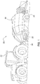
FIG. 2 is a schematic side view of the baler. -
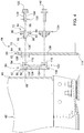
FIG. 3 is a schematic plan view of a reciprocating plunger within a compression chamber of the baler. -
FIG. 4 is a schematic exploded side cross-sectional view of a scraper assembly. -
FIG. 5 is a schematic side cross-sectional view of the scraper assembly. -
FIG. 6 is a schematic perspective cross-sectional view of the scraper assembly. -
FIG. 7 is a schematic perspective view of a cam insert of the scraper assembly. -
FIG. 8 is a schematic plan view of the cam insert. -
FIG. 9 is a schematic cross sectional view of the cam insert. -
FIG. 10 is a schematic plan view of a mounting plate of the scraper assembly. - Those having ordinary skill in the art will recognize that terms such as "above," "below," "upward," "downward," "top," "bottom," etc., are used descriptively for the figures, and do not represent limitations on the scope of the disclosure, as defined by the appended claims. Furthermore, the teachings may be described herein in terms of functional and/or logical block components and/or various processing steps. It should be realized that such block components may be comprised of any number of hardware, software, and/or firmware components configured to perform the specified functions.
- Referring to the Figures, wherein like numerals indicate like parts throughout the several views, a baler is generally shown at 20 in
FIGS. 1 and2 . Referring toFIGS. 1 and2 thebaler 20 is shown as a largesquare baler 20. However, it should be appreciated that the teachings of this disclosure may be applied toother baler 20 platforms, and are not limited to the exemplary embodiment of the largesquare baler 20 shown in the Figures and described herein. - As shown in
FIG. 1 , a vehicle, such as but not limited to atractor 22, is coupled to thebaler 20 for pulling and powering thebaler 20. However, it should be appreciated that in other embodiments thebaler 20 may be self-propelled. As depicted inFIG. 1 , thebaler 20 may move across a field and gather and process crop material to form a bale. Thebaler 20 may then eject the formed bale from the rear of thebaler 20. - Referring to
FIG. 2 , the exemplary embodiment of thebaler 20 includes a frame, ground engaging devices, such as but not limited towheels 24, ahitch 26 for attachment to thetractor 22 or other vehicle, and aninput shaft 28, such as a power-take-off (PTO) shaft, which can receive rotational power from a power source, such as thetractor 22. Thebaler 20 includes a pick-upmechanism 30 which gathers crop material from the ground surface and feeds it into thebaler 20. The pick-upmechanism 30 may include various pick-up apparatus including, but not limited to, tines, forks, augers, conveyors, baffles, a cutter or pre-cutter assembly, or any combination of the preceding. Thebaler 20 includes a housing orbody 32, which generally shields various internal components of thebaler 20. Thebody 32 includesmultiple wall 48 sections that form a compression chamber 34 (shown inFIG. 2 ) used for forming the bale. - The
input shaft 28 or PTO shaft is connected to an input of atransmission 36 to provide rotational power to thebaler 20 from thetractor 22 or other associated vehicle or power source. Thetransmission 36 includes a gearbox which converts the rotational motion of theinput shaft 28 along a generally longitudinal axis of thebaler 20 to an output of thetransmission 36 having a rotational motion along a generally transverse axis of thebaler 20. - The
baler 20 includes acrank arm 38 connected to the output of thetransmission 36. A connectingling 40 interconnects thecrank arm 38 and aplunger 42. Thecrank arm 38 rotates based upon the output of thetransmission 36 and theplunger 42 moves in a reciprocal motion within thecompression chamber 34 as thecrank arm 38 rotates. Theplunger 42 extends into thecompression chamber 34, thereby compressing the crop material, and then at least partially retracts from thecompression chamber 34 to allow more crop material to enter thecompression chamber 34. - Referring to
FIG. 3 , thebaler 20 further includes ascraper assembly 44. Thescraper assembly 44 is attached to aforward face 46 of theplunger 42, and is operable to scrape along thewalls 48 of thebody 32 forming thecompression chamber 34 to prevent or limit crop material from extruding past theface 46 of theplunger 42, and becoming lodged between theplunger 42 and thewalls 48 of thebody 32 forming thecompression chamber 34. - Referring to
FIGS. 4-6 , thescraper assembly 44 includes a mountingplate 50 that is configured for attachment to theface 46 of theplunger 42. The mountingplate 50 may be attached to theface 46 of theplunger 42 in a suitable manner that securely affixes the mountingplate 50 to theplunger 42. For example, the mountingplate 50 may be bolted to theface 46 of theplunger 42, welded to theface 46 of theplunger 42, or attached to theface 46 of theplunger 42 using some other form of fastener or connector not described herein. In other embodiments, it is contemplated that the mountingplate 50 may be integrally formed with and/or defined by theface 46 of theplunger 42. - As best shown in
FIG. 6 , the mountingplate 50 includes afirst surface 52 disposed adjacent to and in abutting engagement with theface 46 of theplunger 42. The mountingplate 50 includes asecond surface 54 that is disposed opposite thefirst surface 52 of the mountingplate 50, and faces away from theface 46 of theplunger 42. The mountingplate 50 includes an annularcountersunk region 56 formed into thesecond surface 54 of the mountingplate 50. A mountingbore 58 extends into the mountingplate 50, and is substantially concentric with the annular countersunkregion 56. The mounting bore 58 may extend completely through the mountingplate 50, or may be a blind bore that does not extend completely through the mountingplate 50. - Referring to
FIGS. 4-6 , thescraper assembly 44 further includes afollower plate 60. As best shown inFIG. 6 , thefollower plate 60 includes afirst surface 62 disposed adjacent to and in abutting engagement with thesecond surface 54 of the mountingplate 50. Thefollower plate 60 includes a second orexterior surface 64 that is disposed opposite thefirst surface 62 of thefollower plate 60, and faces away from theface 46 of theplunger 42. Thefollower plate 60 includes anannular aperture 66 that extends between thefirst surface 62 and thesecond surface 54 of thefollower plate 60. Theannular aperture 66 includes or defines an aperture area perpendicular to acentral axis 68 of the annular countersunkregion 56. - Referring to
FIGS. 4-6 , ascraper plate 70 may be attached to thefollower plate 60. In the exemplary embodiment of thescraper assembly 44 shown in the Figures and described herein, thescraper plate 70 is arranged substantially perpendicular relative to thefollower plate 60 to form an approximate right angle therebetween. However, it should be appreciated that thescraper plate 70 may alternatively be arranged relative to thefollower plate 60 to form a non-right angle therebetween. Thescraper plate 70 is shaped and arranged for scraping thewall 48 of thecompression chamber 34. While the exemplary embodiment of thescraper assembly 44 is shown including thescraper plate 70, it should be appreciated that a lateral edge of thefollower plate 60 may be used to scrape thewall 48 of thecompression chamber 34, such that thescraper assembly 44 does not include thescraper plate 70 shown in the exemplary embodiment. - Referring to
FIGS. 4-9 , thescraper assembly 44 further includes acam insert 72. Thecam insert 72 includes aneccentric connection 74 interconnecting theannular aperture 66 of thefollower plate 60 and the annular countersunkregion 56 of the mountingplate 50. Because of theeccentric connection 74, rotation of thecam insert 72 moves thefollower plate 60 relative to the mountingplate 50. It should be appreciated that the rotation of thecam insert 72 moves thefollower plate 60 in two dimensions, e.g., a vertical dimension, indicated byarrow 76, and a lateral dimension, indicated byarrow 78, relative to theface 46 of theplunger 42. - The
cam insert 72 includes abase portion 80 having aninner surface 82 disposed against the second orexterior surface 64 of thefollower plate 60. Anexterior edge 84 of thebase portion 80 forms a cross sectional shape perpendicular to thecentral axis 68 of the annular countersunkregion 56. The cross-sectional shape of thebase portion 80 includes or defines a base area. The base area is larger than the aperture area, such that thebase portion 80 provides a significant surface contact area in abutting contact with the second orexterior surface 64 of thefollower plate 60 for communicating a clamping force therebetween. In the exemplary embodiment shown in the Figures and described herein, the cross-sectional shape of thebase portion 80 is a hexagon. However, it should be appreciated that the cross-sectional shape of thebase portion 80 may include some other shape. Preferably, however, the cross-sectional shape of thebase portion 80 provides a convenient shape for engaging a tool for rotating thebase portion 80, such as the exemplary hexagonal shape shown in the Figures. - The
cam insert 72 further includes a firstannular projection 86 and a secondannular projection 88. The firstannular projection 86 of thecam insert 72 is seated within theannular aperture 66 of thefollower plate 60. The firstannular projection 86 is substantially concentric with thebase portion 80 of the of thecam insert 72. The secondannular projection 88 of thecam insert 72 is seated within the annular countersunkregion 56 of the mountingplate 50. The secondannular projection 88 of thecam insert 72 is eccentrically located relative to the first annual projection and thebase portion 80. - The first projection extends away from the
inner surface 82 of the base portion 80 afirst distance 90. The second projection extends away from theinner surface 82 of the base portion 80 asecond distance 92. Thesecond distance 92 is greater than thefirst distance 90 such that the second projection extends farther away from theinner surface 82 of thebase portion 80 than the first projection. - The
cam insert 72 further includes a throughbore 94 that extends through thebase portion 80 and the secondannular projection 88. The throughbore 94 is substantially concentric with the secondannular projection 88. The secondannular projection 88 and the throughbore 94 are eccentric relative to the firstannular projection 86 and thebase portion 80. In other words, acentral axis 96 of the throughbore 94 and the secondannular projection 88 is laterally offset an offsetdistance 98 relative to acentral axis 100 of the firstannular projection 86 and thebase portion 80. Additionally, thecentral axis 96 of the throughbore 94 and the secondannular projection 88 is substantially coaxially located with thecentral axis 68 of the annular countersunkregion 56. - A
fastener 102 extends through the throughbore 94 of thecam insert 72, and is disposed in interlocking engagement with the mountingplate 50. Thefastener 102 provides a clamping force to thebase portion 80 of thecam insert 72, which in turn clamps thefollower plate 60 to the mountingplate 50 to secure thefollower plate 60 relative to the mountingplate 50. In the exemplary embodiment shown in the Figures and described herein, thefastener 102 includesexternal threads 104, and the mounting bore 58 includesinternal threads 106 for threaded engagement with theexternal threads 104 of thefastener 102. Accordingly, thefastener 102 is disposed in threaded engagement with the mountingbore 58. It should be appreciated that thescraper assembly 44 may use some other fastening mechanism or system, other than the threaded engagement between thefastener 102 and the mounting bore 58, to interconnect thefastener 102 and the mountingplate 50, and that the scope of the disclosure is not limited to the exemplary embodiment described herein. - The
annular aperture 66 includes anaperture diameter 108. The firstannular projection 86 includes afirst projection diameter 110. Theaperture diameter 108 is larger than thefirst projection diameter 110 to enable relative movement between the firstannular projection 86 and theannular aperture 66, in a direction perpendicular to thecentral axis 68 of the annular countersunkregion 56. For example, theaperture diameter 108 may be between 0.1 mm and 1.0 mm larger than thefirst projection diameter 110. In the exemplary embodiment shown in the Figures and described herein, theaperture diameter 108 is between 0.350 mm and 0.425 mm larger than thefirst projection diameter 110. - The first
annular projection 86 of thecam insert 72 includes a first projection thickness relative to theinner surface 82 of thebase portion 80. In the exemplary embodiment, the first projection thickness is equal to thefirst distance 90. Thefollower plate 60 includes a plate thickness 114 parallel with thecentral axis 68 of the annular countersunkregion 56. The first projection thickness of the firstannular projection 86 is less than the plate thickness 114 of thefollower plate 60, such that the firstannular projection 86 does not extend past thefirst surface 62 of thefollower plate 60, so that thebase portion 80 of thecam insert 72 is free to exert a clamp force against thefollower plate 60 to clamp thefollower plate 60 to the mountingplate 50. A difference between the first projection thickness i.e., thefirst distance 90, and the plate thickness 114 of thefollower plate 60 may be between the range of 1.0 mm and 2.0 mm. - The annular countersunk
region 56 includes acountersunk diameter 116. The secondannular projection 88 includes asecond projection diameter 118. Thecountersunk diameter 116 is larger than thesecond projection diameter 118 to enable relative movement between the secondannular projection 88 and the annular countersunkregion 56, in a direction perpendicular to thecentral axis 68 of the annular countersunkregion 56. For example, thecountersunk diameter 116 may be between 0.1 mm and 1.0 mm larger than thesecond projection diameter 118. In the exemplary embodiment shown in the Figures and described herein, thecountersunk diameter 116 is between 0.350 mm and 0.425 mm larger than thesecond projection diameter 118. - The second
annular projection 88 of thecam insert 72 extends away from the firstannular projection 86 of thecam insert 72 to define asecond projection thickness 120. The annular countersunkregion 56 is recessed adepth 122 from thesecond surface 54 of the mountingplate 50. Thesecond projection thickness 120 is less than thedepth 122 of the countersunk region, such that the secondannular projection 88 does not bottom out or contact abottom surface 124 of the annular countersunkregion 56, so that thebase portion 80 of thecam insert 72 is free to exert a clamp force against thefollower plate 60 to clamp thefollower plate 60 to the mountingplate 50. A difference between thesecond projection thickness 120 of the secondannular projection 88 and thedepth 122 of the countersunk region may be between the range of 1.0 mm and 2.0 mm. - The through
bore 94 includes aninternal diameter 126. Thefastener 102 includes ashank portion 128 having ashank diameter 130. Theinternal diameter 126 of the throughbore 94 is larger than theshank diameter 130 of thefastener 102 to limit shear force transfer between thecam insert 72 and theshank portion 128 of thefastener 102. By sizing theinternal diameter 126 of the through bore 94 to be larger than theshank diameter 130 of thefastener 102, interaction between theannular aperture 66 of thefollower plate 60 and the firstannular projection 86 of thecam insert 72 communicates shear forces imparted by thefollower plate 60 to thecam insert 72, such that interaction between the secondannular projection 88 and the annular countersunkregion 56 may transfer the shear forces to the mountingplate 50. As such, thefastener 102 is operable to provide a clamping force to secure thefollower plate 60 to the mountingplate 50, and does not have to transfer any or significant shear forces therebetween. In one embodiment, the difference between theinternal diameter 126 of the throughbore 94 and theshank diameter 130 of thefastener 102 is greater than the difference between theaperture diameter 108 and thefirst projection diameter 110. - In operation, the
fastener 102 is tightened to provide the clamping force to thecam insert 72. Thebase portion 80 of thecam insert 72 is thereby pressed against the second orexterior surface 64 of thefollower plate 60, and clamps thefollower plate 60 to the mountingplate 50. In order to adjust the position of thefollower plate 60 relative to the mountingplate 50, thefastener 102 is loosened, and thebase portion 80 of thecam insert 72 is rotated. Because of the interaction and/or engagement between the secondannular projection 88 and the annular counter sunk region, thecam insert 72 rotates about thecentral axis 68 of the annular countersunkregion 56. Because the secondannular projection 88 is eccentric relative to the firstannular projection 86, the firstannular projection 86 and thebase portion 80 swing along an arcuate path 132, moving the firstannular projection 86 and thebase portion 80 of thecam insert 72 in two dimensions, e.g., thevertical dimension 76 and thelateral dimension 78 relative to theface 46 of theplunger 42. Because of the interaction and/or engagement between the firstannular projection 86 and theannular aperture 66 of thefollower plate 60, thefollower plate 60 follows the movement of thecam insert 72 as thecam insert 72 is rotated, thereby moving thefollower plate 60 with thecam insert 72. - Referring to
FIGS. 4-6 , the mountingplate 50 may further include asecond cam insert 134. The features and operation of thesecond cam insert 134 is identical to thefirst cam insert 72 described above. Accordingly, thesecond cam insert 134 is not described in detail herein. However, briefly described, the mountingplate 50 includes a second annular countersunkregion 136, and thefollower plate 60 includes a secondannular aperture 138. Thesecond cam insert 134 includes a firstannular projection 86 seated within the secondannular aperture 138 of thefollower plate 60, and a secondannular projection 88 seated within the second annular countersunkregion 136 of the mountingplate 50. A throughbore 94 extends through the secondannular projection 88 of thesecond cam insert 134. Asecond fastener 140 extends through the throughbore 94 of thesecond cam insert 134, and is disposed in interlocking engagement with the mountingplate 50 for securing thefollower plate 60 relative to the mountingplate 50. - Because of the tolerances between the
annular aperture 66 and the firstannular projection 86 of thefirst cam insert 72, and between the secondannular aperture 138 and the firstannular projection 86 of thesecond cam insert 134, and the tolerances between the annular countersunkregion 56 and the secondannular projection 88 of thefirst cam insert 72, and between the second annular countersunkregion 136 and the secondannular projection 88 of thesecond cam insert 134, a position of thefollower plate 60, and thereby thescraper plate 70, may be adjusted to provide an angular adjustment of thefollower plate 60 to match the position of thewall 48 of thecompression chamber 34. In other words, thefirst cam insert 72 and thesecond cam insert 134 may rotated to a different angular degree or position, thereby providing an angular adjustment to thefollower plate 60 relative to thewall 48 of thecompression chamber 34. - Additionally, referring to
FIG. 10 , the mountingplate 50 may include multiple pairs of the first annular countersunkregion 56 and the second annular countersunkregion 136, thereby providing two different mounting positions for thefollower plate 60 relative to the mountingplate 50. - The detailed description and the drawings or figures are supportive and descriptive of the disclosure, but the scope of the disclosure is defined solely by the claims. While some of the best modes and other embodiments for carrying out the claimed teachings have been described in detail, various alternative designs and embodiments exist for practicing the disclosure defined in the appended claims.
Claims (15)
- A scraper assembly for a baler (20) having a reciprocating plunger (42) moveable within a compression chamber (34), the scraper assembly (44) comprising:a mounting plate (50) configured for attachment to a face of the plunger (42), wherein the mounting plate (50) includes an annular countersunk region (56);a follower plate (60) having an annular aperture (66);a cam insert (72) including an eccentric connection interconnecting the annular aperture (66) of the follower plate (60) and the annular countersunk region (56) of the mounting plate (50), such that rotation of the cam insert (72) moves the follower plate (60) relative to the mounting plate (50).
- The scraper assembly set forth in claim 1, wherein the cam insert (72) includes:a first annular projection (86) seated within the annular aperture (66) of the follower plate (60);a second annular projection (88) seated within the annular countersunk region (56) of the mounting plate (50);a through bore (94) extending through the second annular projection (88); anda fastener (102) extending through the through bore (94) of the cam insert (72) and disposed in interlocking engagement with the mounting plate (50) for securing the follower plate (60) relative to the mounting plate (50).
- The scraper assembly set forth in claim 1 or 2, wherein the second annular projection (88) and the through bore (94) are eccentric relative to the first annular projection (86).
- The scraper assembly according to at least one of the claims 1 to 3, wherein the mounting plate (50) includes a mounting bore (58) concentric with the annular countersunk region (56).
- The scraper assembly according to at least one of the claims 1 to 4, wherein the fastener (102) includes external threads (104), and wherein the mounting bore (58) includes internal threads (106) for threaded engagement with the external threads (104) of the fastener (102).
- The scraper assembly according to at least one of the claims 1 to 5, wherein the follower plate (60) includes a scraper plate (70) attached thereto and arranged substantially perpendicular relative to each other.
- The scraper assembly according to at least one of the claims 1 to 6, wherein the annular aperture (66) includes an aperture diameter (108), the first annular projection (86) includes a first projection diameter (110), and wherein the aperture diameter (108) is larger than the first projection diameter (110) to enable relative movement between the first annular projection (86) and the annular aperture (66) in a direction perpendicular to a central axis (96) of the annular countersunk region (56).
- The scraper assembly according to at least one of the claims 1 to 7, wherein the aperture diameter (108) is between 0.1 mm and 1.0 mm larger than the first projection diameter (110).
- The scraper assembly according to at least one of the claims 1 to 8, wherein the annular countersunk region (56) includes a countersunk diameter (116), the second projection includes a second projection diameter (118), and wherein the countersunk diameter (116) is larger than the second projection diameter (118) to enable relative movement between the second annular projection (88) and the annular countersunk region (56) in a direction perpendicular to a central axis (96) of the annular countersunk region (56).
- The scraper assembly according to at least one of the claims 1 to 9, wherein the countersunk diameter (116) is between 0.1 mm and 1.0 mm larger than the second projection diameter (118).
- The scraper assembly according to at least one of the claims 1 to 10, wherein:the cam insert (72) includes a base portion (80) having an inner surface disposed against an exterior surface of the follower plate (60);the first projection extends away from the inner surface a first distance;the second projection extends away from the inner surface a second distance; andthe second distance is greater than the first distance.
- The scraper assembly according to at least one of the claims 1 to 11, wherein the base portion (80) includes an exterior edge (84) forming a cross sectional shape perpendicular to a central axis (96) of the annular countersunk region (56), wherein the cross-sectional shape of the base portion (80) includes a base area, wherein the annular aperture (66) includes an aperture area, and wherein the base area is larger than the aperture area.
- The scraper assembly according to at least one of the claims 1 to 12, wherein the cross-sectional shape of the base portion (80) is a hexagon.
- The scraper assembly according to at least one of the claims 1 to 13, further comprising:wherein the mounting plate (50) includes a second annular countersunk region (56);wherein the follower plate (60) includes a second annular aperture (66);a second cam insert (134) including:a first annular projection (86) seated within the second annular aperture (66) of the follower plate (60);a second annular projection (88) seated within the second annular countersunk region (56) of the mounting plate (50);a through bore (94) extending through the second annular projection (88) of the second cam insert (134); anda second fastener (140) extending through the through bore (94) of the second cam insert (134) and disposed in interlocking engagement with the mounting plate (50) for securing the follower plate (60) relative to the mounting plate (50).
- A baler comprising:a body (32) forming a compression chamber (34);a reciprocating plunger (42) moveable within the compression chamber (34);a scraper assembly (44) including:a mounting plate (50) attached to a face of the reciprocating plunger (42), wherein the mounting plate (50) includes an annular countersunk region (56);a follower plate (60) having an annular aperture (66);a scraper plate (70) attached to the follower plate (60);a cam insert (72) including a first annular projection (86) seated within the annular aperture (66) of the follower plate (60), a second annular projection (88) seated within the annular countersunk region (56) of the mounting plate (50), and a through bore (94) extending through the second annular projection (88); anda fastener (102) extending through the through bore (94) of the cam insert (72) and disposed in interlocking engagement with the mounting plate (50) for securing the follower plate (60) relative to the mounting plate (50).
Applications Claiming Priority (1)
| Application Number | Priority Date | Filing Date | Title |
|---|---|---|---|
| US16/435,959 US10999974B2 (en) | 2019-06-10 | 2019-06-10 | Plunger scraper for reciprocating baler |
Publications (2)
| Publication Number | Publication Date |
|---|---|
| EP3750396A1 true EP3750396A1 (en) | 2020-12-16 |
| EP3750396B1 EP3750396B1 (en) | 2024-04-17 |
Family
ID=70977755
Family Applications (1)
| Application Number | Title | Priority Date | Filing Date |
|---|---|---|---|
| EP20178173.9A Active EP3750396B1 (en) | 2019-06-10 | 2020-06-04 | Plunger scraper for reciprocating baler |
Country Status (2)
| Country | Link |
|---|---|
| US (1) | US10999974B2 (en) |
| EP (1) | EP3750396B1 (en) |
Families Citing this family (3)
| Publication number | Priority date | Publication date | Assignee | Title |
|---|---|---|---|---|
| DE102021102348A1 (en) * | 2021-02-02 | 2022-08-04 | Usines Claas France S.A.S. | Agricultural square baler |
| US11534998B2 (en) * | 2021-02-15 | 2022-12-27 | Sebright Products, Inc. | Baling assembly with a support structure |
| CN120828556B (en) * | 2025-09-16 | 2026-02-10 | 四川味欣生物科技股份有限公司 | Natural essence and spice extraction, preparation and processing system and method |
Citations (3)
| Publication number | Priority date | Publication date | Assignee | Title |
|---|---|---|---|---|
| US20100242749A1 (en) * | 2009-03-25 | 2010-09-30 | Carl Frans Demulder | Modular Baler Plunger |
| US10051792B2 (en) * | 2014-01-30 | 2018-08-21 | Cnh Industrial America Llc | Agricultural baler with a plunger slot belt |
| US10398086B2 (en) * | 2013-08-01 | 2019-09-03 | Cnh Industrial America Llc | Rectangular baler |
Family Cites Families (6)
| Publication number | Priority date | Publication date | Assignee | Title |
|---|---|---|---|---|
| US3270418A (en) | 1964-04-21 | 1966-09-06 | Robert A Simeone | Rifle sight |
| US4417510A (en) * | 1981-09-28 | 1983-11-29 | Al-Jon, Inc. | Shear baler |
| DE19646951A1 (en) * | 1996-11-13 | 1998-05-14 | Hilti Ag | Fastener |
| BE1019886A3 (en) * | 2011-03-22 | 2013-02-05 | Cnh Belgium Nv | ALIGNMENT OF PLUNGER WITH GEARBOX IN A BALL PRESS. |
| BE1021885B1 (en) * | 2014-07-03 | 2016-01-25 | Cnh Industrial Belgium Nv | PLUNGER SLIDE COVER UNIT FOR A BALING PRESS FOR USE IN AGRICULTURE. |
| DE102015213854A1 (en) | 2015-07-22 | 2017-01-26 | Deere & Company | Scraper bar, scraper device and agricultural round baler with such |
-
2019
- 2019-06-10 US US16/435,959 patent/US10999974B2/en active Active
-
2020
- 2020-06-04 EP EP20178173.9A patent/EP3750396B1/en active Active
Patent Citations (3)
| Publication number | Priority date | Publication date | Assignee | Title |
|---|---|---|---|---|
| US20100242749A1 (en) * | 2009-03-25 | 2010-09-30 | Carl Frans Demulder | Modular Baler Plunger |
| US10398086B2 (en) * | 2013-08-01 | 2019-09-03 | Cnh Industrial America Llc | Rectangular baler |
| US10051792B2 (en) * | 2014-01-30 | 2018-08-21 | Cnh Industrial America Llc | Agricultural baler with a plunger slot belt |
Also Published As
| Publication number | Publication date |
|---|---|
| EP3750396B1 (en) | 2024-04-17 |
| US10999974B2 (en) | 2021-05-11 |
| US20200383272A1 (en) | 2020-12-10 |
Similar Documents
| Publication | Publication Date | Title |
|---|---|---|
| EP3750396B1 (en) | Plunger scraper for reciprocating baler | |
| DE60017984T2 (en) | Apparatus and method for displaying the baling capacity | |
| EP3554216B1 (en) | Adjustable stuffer chute | |
| EP3398420A1 (en) | Method and assembly for controlling the speed a baler | |
| DE19831506A1 (en) | Baler for agricultural crops to produce rectangular bales | |
| US6470560B1 (en) | Method for making a shaft coupling with tapered spines for a pull-type forage harvester | |
| EP4070645A1 (en) | Bale ejection system for a baler implement | |
| US4354430A (en) | Bale tension apparatus | |
| US12041884B2 (en) | Agricultural baling machines | |
| US5090307A (en) | Shear bolt coupling and method of replacing a shear bolt | |
| US20210243959A1 (en) | Agricultural baling machines | |
| US3943845A (en) | Replaceable feeder fingers for a baler | |
| US11882794B2 (en) | Stuffer assembly for an agricultural baler | |
| EP3760034B1 (en) | Needle frame assembly and needle coupling for agricultural machine | |
| EP3190868B1 (en) | Baler with improved cross member for mounting the gearbox | |
| CN117099564A (en) | Double-row clamping chain type adjustable-spacing girder cutting and harvesting integrated machine | |
| US12069989B2 (en) | Mounting for a baling machine gearbox | |
| US12137637B2 (en) | Panel compression system for baler implement | |
| EP4445719A1 (en) | Panel compression system for baler implement | |
| DE4216483A1 (en) | Rake conveyor with overload safety device - has intermittent coupling to disconnect drive for period and later reconnect | |
| US20120204737A1 (en) | Tracking Bale Density Door for Big Square Baler | |
| US12120986B2 (en) | Agricultural baling machines | |
| US20210243955A1 (en) | Bale chamber arrangement for an agricultural baler | |
| US11457567B2 (en) | Needle coupling and frame assembly for agricultural machine | |
| JPH0728826Y2 (en) | Combine harvester |
Legal Events
| Date | Code | Title | Description |
|---|---|---|---|
| PUAI | Public reference made under article 153(3) epc to a published international application that has entered the european phase |
Free format text: ORIGINAL CODE: 0009012 |
|
| STAA | Information on the status of an ep patent application or granted ep patent |
Free format text: STATUS: THE APPLICATION HAS BEEN PUBLISHED |
|
| AK | Designated contracting states |
Kind code of ref document: A1 Designated state(s): AL AT BE BG CH CY CZ DE DK EE ES FI FR GB GR HR HU IE IS IT LI LT LU LV MC MK MT NL NO PL PT RO RS SE SI SK SM TR |
|
| AX | Request for extension of the european patent |
Extension state: BA ME |
|
| STAA | Information on the status of an ep patent application or granted ep patent |
Free format text: STATUS: REQUEST FOR EXAMINATION WAS MADE |
|
| 17P | Request for examination filed |
Effective date: 20210616 |
|
| RBV | Designated contracting states (corrected) |
Designated state(s): AL AT BE BG CH CY CZ DE DK EE ES FI FR GB GR HR HU IE IS IT LI LT LU LV MC MK MT NL NO PL PT RO RS SE SI SK SM TR |
|
| GRAP | Despatch of communication of intention to grant a patent |
Free format text: ORIGINAL CODE: EPIDOSNIGR1 |
|
| STAA | Information on the status of an ep patent application or granted ep patent |
Free format text: STATUS: GRANT OF PATENT IS INTENDED |
|
| INTG | Intention to grant announced |
Effective date: 20231218 |
|
| GRAS | Grant fee paid |
Free format text: ORIGINAL CODE: EPIDOSNIGR3 |
|
| GRAA | (expected) grant |
Free format text: ORIGINAL CODE: 0009210 |
|
| STAA | Information on the status of an ep patent application or granted ep patent |
Free format text: STATUS: THE PATENT HAS BEEN GRANTED |
|
| AK | Designated contracting states |
Kind code of ref document: B1 Designated state(s): AL AT BE BG CH CY CZ DE DK EE ES FI FR GB GR HR HU IE IS IT LI LT LU LV MC MK MT NL NO PL PT RO RS SE SI SK SM TR |
|
| REG | Reference to a national code |
Ref country code: GB Ref legal event code: FG4D |
|
| REG | Reference to a national code |
Ref country code: CH Ref legal event code: EP |
|
| REG | Reference to a national code |
Ref country code: DE Ref legal event code: R096 Ref document number: 602020029022 Country of ref document: DE |
|
| REG | Reference to a national code |
Ref country code: IE Ref legal event code: FG4D |
|
| REG | Reference to a national code |
Ref country code: LT Ref legal event code: MG9D |
|
| REG | Reference to a national code |
Ref country code: NL Ref legal event code: MP Effective date: 20240417 |
|
| REG | Reference to a national code |
Ref country code: AT Ref legal event code: MK05 Ref document number: 1676249 Country of ref document: AT Kind code of ref document: T Effective date: 20240417 |
|
| PG25 | Lapsed in a contracting state [announced via postgrant information from national office to epo] |
Ref country code: NL Free format text: LAPSE BECAUSE OF FAILURE TO SUBMIT A TRANSLATION OF THE DESCRIPTION OR TO PAY THE FEE WITHIN THE PRESCRIBED TIME-LIMIT Effective date: 20240417 |
|
| PG25 | Lapsed in a contracting state [announced via postgrant information from national office to epo] |
Ref country code: NL Free format text: LAPSE BECAUSE OF FAILURE TO SUBMIT A TRANSLATION OF THE DESCRIPTION OR TO PAY THE FEE WITHIN THE PRESCRIBED TIME-LIMIT Effective date: 20240417 |
|
| PG25 | Lapsed in a contracting state [announced via postgrant information from national office to epo] |
Ref country code: IS Free format text: LAPSE BECAUSE OF FAILURE TO SUBMIT A TRANSLATION OF THE DESCRIPTION OR TO PAY THE FEE WITHIN THE PRESCRIBED TIME-LIMIT Effective date: 20240817 |
|
| PG25 | Lapsed in a contracting state [announced via postgrant information from national office to epo] |
Ref country code: BG Free format text: LAPSE BECAUSE OF FAILURE TO SUBMIT A TRANSLATION OF THE DESCRIPTION OR TO PAY THE FEE WITHIN THE PRESCRIBED TIME-LIMIT Effective date: 20240417 |
|
| PG25 | Lapsed in a contracting state [announced via postgrant information from national office to epo] |
Ref country code: HR Free format text: LAPSE BECAUSE OF FAILURE TO SUBMIT A TRANSLATION OF THE DESCRIPTION OR TO PAY THE FEE WITHIN THE PRESCRIBED TIME-LIMIT Effective date: 20240417 Ref country code: FI Free format text: LAPSE BECAUSE OF FAILURE TO SUBMIT A TRANSLATION OF THE DESCRIPTION OR TO PAY THE FEE WITHIN THE PRESCRIBED TIME-LIMIT Effective date: 20240417 |
|
| PG25 | Lapsed in a contracting state [announced via postgrant information from national office to epo] |
Ref country code: GR Free format text: LAPSE BECAUSE OF FAILURE TO SUBMIT A TRANSLATION OF THE DESCRIPTION OR TO PAY THE FEE WITHIN THE PRESCRIBED TIME-LIMIT Effective date: 20240718 |
|
| PG25 | Lapsed in a contracting state [announced via postgrant information from national office to epo] |
Ref country code: PT Free format text: LAPSE BECAUSE OF FAILURE TO SUBMIT A TRANSLATION OF THE DESCRIPTION OR TO PAY THE FEE WITHIN THE PRESCRIBED TIME-LIMIT Effective date: 20240819 |
|
| PG25 | Lapsed in a contracting state [announced via postgrant information from national office to epo] |
Ref country code: ES Free format text: LAPSE BECAUSE OF FAILURE TO SUBMIT A TRANSLATION OF THE DESCRIPTION OR TO PAY THE FEE WITHIN THE PRESCRIBED TIME-LIMIT Effective date: 20240417 |
|
| PG25 | Lapsed in a contracting state [announced via postgrant information from national office to epo] |
Ref country code: AT Free format text: LAPSE BECAUSE OF FAILURE TO SUBMIT A TRANSLATION OF THE DESCRIPTION OR TO PAY THE FEE WITHIN THE PRESCRIBED TIME-LIMIT Effective date: 20240417 |
|
| PG25 | Lapsed in a contracting state [announced via postgrant information from national office to epo] |
Ref country code: PL Free format text: LAPSE BECAUSE OF FAILURE TO SUBMIT A TRANSLATION OF THE DESCRIPTION OR TO PAY THE FEE WITHIN THE PRESCRIBED TIME-LIMIT Effective date: 20240417 |
|
| PG25 | Lapsed in a contracting state [announced via postgrant information from national office to epo] |
Ref country code: LV Free format text: LAPSE BECAUSE OF FAILURE TO SUBMIT A TRANSLATION OF THE DESCRIPTION OR TO PAY THE FEE WITHIN THE PRESCRIBED TIME-LIMIT Effective date: 20240417 |
|
| PG25 | Lapsed in a contracting state [announced via postgrant information from national office to epo] |
Ref country code: PT Free format text: LAPSE BECAUSE OF FAILURE TO SUBMIT A TRANSLATION OF THE DESCRIPTION OR TO PAY THE FEE WITHIN THE PRESCRIBED TIME-LIMIT Effective date: 20240819 Ref country code: PL Free format text: LAPSE BECAUSE OF FAILURE TO SUBMIT A TRANSLATION OF THE DESCRIPTION OR TO PAY THE FEE WITHIN THE PRESCRIBED TIME-LIMIT Effective date: 20240417 Ref country code: NO Free format text: LAPSE BECAUSE OF FAILURE TO SUBMIT A TRANSLATION OF THE DESCRIPTION OR TO PAY THE FEE WITHIN THE PRESCRIBED TIME-LIMIT Effective date: 20240717 Ref country code: LV Free format text: LAPSE BECAUSE OF FAILURE TO SUBMIT A TRANSLATION OF THE DESCRIPTION OR TO PAY THE FEE WITHIN THE PRESCRIBED TIME-LIMIT Effective date: 20240417 Ref country code: IS Free format text: LAPSE BECAUSE OF FAILURE TO SUBMIT A TRANSLATION OF THE DESCRIPTION OR TO PAY THE FEE WITHIN THE PRESCRIBED TIME-LIMIT Effective date: 20240817 Ref country code: HR Free format text: LAPSE BECAUSE OF FAILURE TO SUBMIT A TRANSLATION OF THE DESCRIPTION OR TO PAY THE FEE WITHIN THE PRESCRIBED TIME-LIMIT Effective date: 20240417 Ref country code: GR Free format text: LAPSE BECAUSE OF FAILURE TO SUBMIT A TRANSLATION OF THE DESCRIPTION OR TO PAY THE FEE WITHIN THE PRESCRIBED TIME-LIMIT Effective date: 20240718 Ref country code: FI Free format text: LAPSE BECAUSE OF FAILURE TO SUBMIT A TRANSLATION OF THE DESCRIPTION OR TO PAY THE FEE WITHIN THE PRESCRIBED TIME-LIMIT Effective date: 20240417 Ref country code: ES Free format text: LAPSE BECAUSE OF FAILURE TO SUBMIT A TRANSLATION OF THE DESCRIPTION OR TO PAY THE FEE WITHIN THE PRESCRIBED TIME-LIMIT Effective date: 20240417 Ref country code: BG Free format text: LAPSE BECAUSE OF FAILURE TO SUBMIT A TRANSLATION OF THE DESCRIPTION OR TO PAY THE FEE WITHIN THE PRESCRIBED TIME-LIMIT Effective date: 20240417 Ref country code: AT Free format text: LAPSE BECAUSE OF FAILURE TO SUBMIT A TRANSLATION OF THE DESCRIPTION OR TO PAY THE FEE WITHIN THE PRESCRIBED TIME-LIMIT Effective date: 20240417 Ref country code: RS Free format text: LAPSE BECAUSE OF FAILURE TO SUBMIT A TRANSLATION OF THE DESCRIPTION OR TO PAY THE FEE WITHIN THE PRESCRIBED TIME-LIMIT Effective date: 20240717 |
|
| PG25 | Lapsed in a contracting state [announced via postgrant information from national office to epo] |
Ref country code: DK Free format text: LAPSE BECAUSE OF FAILURE TO SUBMIT A TRANSLATION OF THE DESCRIPTION OR TO PAY THE FEE WITHIN THE PRESCRIBED TIME-LIMIT Effective date: 20240417 |
|
| REG | Reference to a national code |
Ref country code: DE Ref legal event code: R097 Ref document number: 602020029022 Country of ref document: DE |
|
| PG25 | Lapsed in a contracting state [announced via postgrant information from national office to epo] |
Ref country code: EE Free format text: LAPSE BECAUSE OF FAILURE TO SUBMIT A TRANSLATION OF THE DESCRIPTION OR TO PAY THE FEE WITHIN THE PRESCRIBED TIME-LIMIT Effective date: 20240417 |
|
| PG25 | Lapsed in a contracting state [announced via postgrant information from national office to epo] |
Ref country code: CZ Free format text: LAPSE BECAUSE OF FAILURE TO SUBMIT A TRANSLATION OF THE DESCRIPTION OR TO PAY THE FEE WITHIN THE PRESCRIBED TIME-LIMIT Effective date: 20240417 |
|
| PG25 | Lapsed in a contracting state [announced via postgrant information from national office to epo] |
Ref country code: SK Free format text: LAPSE BECAUSE OF FAILURE TO SUBMIT A TRANSLATION OF THE DESCRIPTION OR TO PAY THE FEE WITHIN THE PRESCRIBED TIME-LIMIT Effective date: 20240417 Ref country code: RO Free format text: LAPSE BECAUSE OF FAILURE TO SUBMIT A TRANSLATION OF THE DESCRIPTION OR TO PAY THE FEE WITHIN THE PRESCRIBED TIME-LIMIT Effective date: 20240417 |
|
| PG25 | Lapsed in a contracting state [announced via postgrant information from national office to epo] |
Ref country code: SM Free format text: LAPSE BECAUSE OF FAILURE TO SUBMIT A TRANSLATION OF THE DESCRIPTION OR TO PAY THE FEE WITHIN THE PRESCRIBED TIME-LIMIT Effective date: 20240417 |
|
| PG25 | Lapsed in a contracting state [announced via postgrant information from national office to epo] |
Ref country code: SM Free format text: LAPSE BECAUSE OF FAILURE TO SUBMIT A TRANSLATION OF THE DESCRIPTION OR TO PAY THE FEE WITHIN THE PRESCRIBED TIME-LIMIT Effective date: 20240417 Ref country code: SK Free format text: LAPSE BECAUSE OF FAILURE TO SUBMIT A TRANSLATION OF THE DESCRIPTION OR TO PAY THE FEE WITHIN THE PRESCRIBED TIME-LIMIT Effective date: 20240417 Ref country code: RO Free format text: LAPSE BECAUSE OF FAILURE TO SUBMIT A TRANSLATION OF THE DESCRIPTION OR TO PAY THE FEE WITHIN THE PRESCRIBED TIME-LIMIT Effective date: 20240417 Ref country code: EE Free format text: LAPSE BECAUSE OF FAILURE TO SUBMIT A TRANSLATION OF THE DESCRIPTION OR TO PAY THE FEE WITHIN THE PRESCRIBED TIME-LIMIT Effective date: 20240417 Ref country code: DK Free format text: LAPSE BECAUSE OF FAILURE TO SUBMIT A TRANSLATION OF THE DESCRIPTION OR TO PAY THE FEE WITHIN THE PRESCRIBED TIME-LIMIT Effective date: 20240417 Ref country code: CZ Free format text: LAPSE BECAUSE OF FAILURE TO SUBMIT A TRANSLATION OF THE DESCRIPTION OR TO PAY THE FEE WITHIN THE PRESCRIBED TIME-LIMIT Effective date: 20240417 Ref country code: MC Free format text: LAPSE BECAUSE OF FAILURE TO SUBMIT A TRANSLATION OF THE DESCRIPTION OR TO PAY THE FEE WITHIN THE PRESCRIBED TIME-LIMIT Effective date: 20240417 |
|
| REG | Reference to a national code |
Ref country code: CH Ref legal event code: PL |
|
| PG25 | Lapsed in a contracting state [announced via postgrant information from national office to epo] |
Ref country code: IT Free format text: LAPSE BECAUSE OF FAILURE TO SUBMIT A TRANSLATION OF THE DESCRIPTION OR TO PAY THE FEE WITHIN THE PRESCRIBED TIME-LIMIT Effective date: 20240417 |
|
| PG25 | Lapsed in a contracting state [announced via postgrant information from national office to epo] |
Ref country code: LU Free format text: LAPSE BECAUSE OF NON-PAYMENT OF DUE FEES Effective date: 20240604 |
|
| PLBE | No opposition filed within time limit |
Free format text: ORIGINAL CODE: 0009261 |
|
| STAA | Information on the status of an ep patent application or granted ep patent |
Free format text: STATUS: NO OPPOSITION FILED WITHIN TIME LIMIT |
|
| 26N | No opposition filed |
Effective date: 20250120 |
|
| GBPC | Gb: european patent ceased through non-payment of renewal fee |
Effective date: 20240717 |
|
| PG25 | Lapsed in a contracting state [announced via postgrant information from national office to epo] |
Ref country code: IE Free format text: LAPSE BECAUSE OF NON-PAYMENT OF DUE FEES Effective date: 20240604 |
|
| PG25 | Lapsed in a contracting state [announced via postgrant information from national office to epo] |
Ref country code: BE Free format text: LAPSE BECAUSE OF NON-PAYMENT OF DUE FEES Effective date: 20240630 Ref country code: CH Free format text: LAPSE BECAUSE OF NON-PAYMENT OF DUE FEES Effective date: 20240630 Ref country code: SI Free format text: LAPSE BECAUSE OF FAILURE TO SUBMIT A TRANSLATION OF THE DESCRIPTION OR TO PAY THE FEE WITHIN THE PRESCRIBED TIME-LIMIT Effective date: 20240417 |
|
| PG25 | Lapsed in a contracting state [announced via postgrant information from national office to epo] |
Ref country code: GB Free format text: LAPSE BECAUSE OF NON-PAYMENT OF DUE FEES Effective date: 20240717 |
|
| REG | Reference to a national code |
Ref country code: BE Ref legal event code: MM Effective date: 20240630 |
|
| PGFP | Annual fee paid to national office [announced via postgrant information from national office to epo] |
Ref country code: DE Payment date: 20250521 Year of fee payment: 6 |
|
| PGFP | Annual fee paid to national office [announced via postgrant information from national office to epo] |
Ref country code: FR Payment date: 20250625 Year of fee payment: 6 |
|
| PG25 | Lapsed in a contracting state [announced via postgrant information from national office to epo] |
Ref country code: SE Free format text: LAPSE BECAUSE OF FAILURE TO SUBMIT A TRANSLATION OF THE DESCRIPTION OR TO PAY THE FEE WITHIN THE PRESCRIBED TIME-LIMIT Effective date: 20240417 |
|
| PG25 | Lapsed in a contracting state [announced via postgrant information from national office to epo] |
Ref country code: CY Free format text: LAPSE BECAUSE OF FAILURE TO SUBMIT A TRANSLATION OF THE DESCRIPTION OR TO PAY THE FEE WITHIN THE PRESCRIBED TIME-LIMIT; INVALID AB INITIO Effective date: 20200604 |
|
| PG25 | Lapsed in a contracting state [announced via postgrant information from national office to epo] |
Ref country code: HU Free format text: LAPSE BECAUSE OF FAILURE TO SUBMIT A TRANSLATION OF THE DESCRIPTION OR TO PAY THE FEE WITHIN THE PRESCRIBED TIME-LIMIT; INVALID AB INITIO Effective date: 20200604 |