EP3750395B1 - A tine arm for an agricultural machine for working grass, hay or other crops - Google Patents
A tine arm for an agricultural machine for working grass, hay or other crops Download PDFInfo
- Publication number
- EP3750395B1 EP3750395B1 EP20184315.8A EP20184315A EP3750395B1 EP 3750395 B1 EP3750395 B1 EP 3750395B1 EP 20184315 A EP20184315 A EP 20184315A EP 3750395 B1 EP3750395 B1 EP 3750395B1
- Authority
- EP
- European Patent Office
- Prior art keywords
- locking pin
- arm part
- arm
- locking
- hinge
- Prior art date
- Legal status (The legal status is an assumption and is not a legal conclusion. Google has not performed a legal analysis and makes no representation as to the accuracy of the status listed.)
- Active
Links
Images

Classifications
-
- A—HUMAN NECESSITIES
- A01—AGRICULTURE; FORESTRY; ANIMAL HUSBANDRY; HUNTING; TRAPPING; FISHING
- A01D—HARVESTING; MOWING
- A01D78/00—Haymakers with tines moving with respect to the machine
- A01D78/08—Haymakers with tines moving with respect to the machine with tine-carrying rotary heads or wheels
- A01D78/10—Haymakers with tines moving with respect to the machine with tine-carrying rotary heads or wheels the tines rotating about a substantially vertical axis
- A01D78/1007—Arrangements to facilitate transportation specially adapted therefor
Definitions
- a tine arm for an agricultural machine for working grass, hay or other crops is provided.
- the present invention relates to a rake element arm for an agricultural machine for working grass, hay or other crops on the field, as well as such an agricultural machine.
- EP1362505A1 discloses a machine for working grass, hay or other crops.
- This machine comprises a frame that can be pulled by a pulling vehicle, for example a tractor.
- a pulling vehicle for example a tractor.
- On the frame one end of a rake member arm is mounted.
- the other end of the rake member arm supports a rake member.
- the rake member comprises a centre body, rotatably mounted on the rake member arm, a plurality of rake element arms extending from the centre body, and one or more rake elements mounted on each rake element arm.
- the rake member arm is movable between a transport position in which the rake element arm extends in a substantially vertical plane and a working position in which the rake element arm extends in a substantially horizontal plane.
- some of the rake element arms are provided with a hinge that allows an outer arm part of the rake element arm to hinge about the outer end of an inner arm part so as to reduce the length of the rake arm for transport.
- a separate pin is provided that can be arranged in holes provided on the inner arm part and the outer arm part.
- these holes are aligned to allow the pin to be inserted in the holes of both the inner arm part and the outer arm part.
- the separate pin must be taken out of the aligned holes of the inner arm part and the outer arm part, to allow a folding movement of the outer part arm to the transport position.
- a drawback of the machine of EP1362505A1 is that the separate pin is easily lost.
- a rake member comprises a plurality of rake element arms, which may also be referred to as tine arms.
- a first object of the invention is to provide an improved tine arm for such an agricultural machine, which in particular provides a more user-friendly and/or reliable locking device to lock the inner and outer arm part of the foldable tine arm.
- the locking pin housing is a housing that receives the locking pin, while it allows a sliding movement of the locking pin in a direction of movement parallel to its longitudinal axis, whereby the locking pin is movable between the locking position and the non-locking or releasing position.
- the locking pin housing may, for example, be formed by a first locking pin holder and a second locking pin holder, wherein the first and second locking pin holders have openings to receive the locking pin therein.
- a cam may be provided that extends at least partially transversely to the longitudinal axis of the locking pin.
- the cam may be formed by a protrusion arranged on the outer cylindrical surface of the locking pin. The cam cooperates with the cam surface, for example a sloped or curved surface, provided in the locking pin housing, such that rotation of the locking pin about its longitudinal axis results in movement of the cam along the cam surface.
- the cam surface is shaped in such a way that movement of the cam along the cam surface, caused by rotation of the locking pin about its longitudinal axis, results in a movement of locking pin towards the non-locking or releasing position. Rotation of the locking pin in the opposite direction will result in movement of the locking pin towards the locking position.
- the locking device comprises a hinge that hingeably connects the first arm part to the second arm part, wherein the hinge comprises a first hinge part mounted on the first arm part and a second hinge part mounted on the second arm part.
- the first arm part and the second arm part are hingeably connected to each other about a hinge axis.
- the hinge axis is defined by a hinge which may comprise a first hinge part mounted on the first arm part and a second hinge part mounted on the second arm part.
- the hinge comprises a hinge axis which is arranged at a distance from the end of the second arm part, wherein, as seen in the longitudinal direction of the first and second arm parts in their working position, the first slot is mounted on the second arm part at a first side of the hinge axis, and wherein the second slot is mounted on the second arm part at a second side of the hinge axis opposite to the first side.
- the first slot may, for example, be arranged between the hinge axis and the end of the second arm part located adjacent to the first arm part and the second slot may be arranged at the other side of the hinge axis.
- the second arm part can be pivoted about the hinge axis between the working position, in which the first slot is aligned with the locking pin, and a transport position, in which the second slot is aligned with the locking pin.
- the hinge axis of the hinge may also be spaced from the end of the first arm part in a direction parallel to the longitudinal axis of the first arm part and away from the first arm part.
- the first hinge part comprises a cylindrical part adapted to be mounted on the end of the first arm part, and a recessed cylindrical part adapted to receive a part of the second arm part in the working position.
- substantial forces may be exerted on the rake element arm when grass, hay or other crop is displaced on the field. Therefore, it is advantageous to be able to transfer substantial forces from the second arm part to the first arm part.
- a first hinge part that has a cylindrical part mounted on the end of the first arm part and a recessed, for example half open, cylindrical part to receive a part of the second arm part in the working position, a relative rigid connection between the first arm part and the second arm part is formed. Such a construction may also reduce the forces exerted on the hinge.
- the locking pin is biased towards the locking position.
- the locking pin may, for example, be biased towards the locking position by a spring element.
- a spring element By biasing the locking pin towards the locking position, for example by using a spring element, an inadvertent release of the locking pin between the first arm part and the second arm part in either the working position or the transport position can be avoided or at least substantially be prevented.
- the first and second arm parts can be locked in a very reliable manner.
- the machine comprises two rake members, which are arranged at opposite sides of the frame.
- the machine may also comprise more rake members, for example three, four, five or six rake members.
- each rake member is carried by a respective rake member arm.
- the or each rake member arm is pivotally connected to the frame about a substantially horizontal pivot axis between a rake member working position and a rake member transport position.
- the or each rake member comprises a plurality of rake element arms, wherein not all but only a subset of the rake element arms is foldable as described above.
- the above described rake element arm is of a first foldable type, wherein the rake member comprises a plurality of rake element arms of a second type different from the first foldable type, in particular non-foldable.
- An embodiment according to the invention also relates to a rake member for working grass, hay or other crops on the field as described above.
- a machine for working grass, hay or other crops is generally denoted in figure 1 by reference numeral 1.
- the machine 1 is a rotary rake.
- the machine 1 comprises a frame 2 having a front end 3 configured to be connected to a pulling vehicle, for example a tractor, and a rear end 4 provided with wheels 5 to support the frame 2.
- a rake member arm 6 having a fixed length is provided.
- a trolley carrying a rake member 7 can be displaced in a sliding manner along each rake member arm 6.
- the rake member arm 6 can be constructed in a different manner, for example as a telescopic arm.
- Each rake member 7 comprises a centre body 8 that is rotatably connected to the trolley on the respective rake member arm 6.
- Multiple rake element arms or tine arms 9 are distributed about the circumference of the centre body 8 and extend from the centre body 8. At the distal ends of the rake element arms 9 rake elements 10, for example tines, are provided.
- the rake members 7 are rotated about a substantially vertical axis of rotation of the centre body 8.
- the crops on the field are displaced by the rake elements 10 in order to arrange the crops in a desired configuration on the field.
- the rake member arms 6 and the rake members 7 connected thereto are movable between a working position, in which the rake element arms 9 extend in a substantially horizontal plane (as shown in Figure 1 ), and a transport position in which the rake elements arm extend in a more upright plane, for example in a substantially vertical plane.
- Hydraulic cylinders 11 are provided to actuate the movement of the rake member arms 6 between the working position and the transport position.
- the machine When the machine is not used, it is desirable to bring the machine in a compact configuration. In particular for road transport, it is important that the machine does not exceed a maximum transport height. At the same time it is desirable that the working width during use, i.e. in the working position, is relatively large so that a wide strip of field can be handled by the machine 1.
- the rake element arms 9 comprise an inner arm part 12 and an outer arm part 13 that are pivotally connected to each other between a working position and a transport position.
- the longitudinal axes of the inner arm part 12 and the outer arm part 13 of such a foldable rake element arm 9 coincide such that the configuration of the foldable rake element arms 9 in the working position substantially corresponds to the configuration of the other non-foldable rake element arms 9.
- the outer arm parts 13 may be arranged in a folded position with respect to the inner arm parts 12 such that the maximum radial distance of the outer arm parts 13 with respect to the axis of rotation of the centre body 13 is smaller than the maximum radial distance of the outer arm parts 13 in the working position. This results in a reduced height of the machine 1, when the rake members 7 are pivoted upwards to the transport position, and the folded outer arms 13 are arranged at the upper side of the machine 1 in this transport position.
- the rotated outer arm parts 13 may also result in a reduced width in transport position.
- the rake element arms 9 having an inner arm part 12 and outer arm part 13 that are hingeable with respect to each other comprise a hinge 14 and a locking device.
- the hinge 14 and locking device are schematically indicated by boxes A in figure 1 .
- the hinge 14 and the locking device are shown in more detail in figure 2 .
- FIG 2 the inner arm part 12 and the outer arm part 13 are shown in the working position.
- the inner arm part 12 and the outer arm part 13 are hingeable with respect to each other about a hinge 14 having a hinge axis 15.
- the hinge 14 is formed by a first hinge part 16 mounted on the inner arm part 12, a second hinge part 17 mounted on the outer arm part 13, and also a hinge pin 18.
- the first hinge part 16 comprises a cylindrical part 19 which is mounted on the end of the inner arm part 12, and a recessed, for example half-open, cylindrical part 20 which protrudes from the end of the inner arm part 12 and configured to receive an end part of the outer arm part 13, when the outer arm part 13 is arranged in the working position.
- a recessed, for example half-open, cylindrical part 20 which protrudes from the end of the inner arm part 12 and configured to receive an end part of the outer arm part 13, when the outer arm part 13 is arranged in the working position.
- hinge elements are provided having openings to receive the hinge pin 18.
- the locking pin housing 21 comprises a first locking pin holder 22 and a second locking pin holder 23.
- Each of the first locking pin holder 22 and the second locking pin holder 23 comprises a locking pin receiving hole through which a locking pin 24 extends.
- the inner diameter of the locking pin receiving holes of the first and second locking pin holders 22, 23 substantially corresponds to the outer diameter of the locking pin 24 such that the locking pin 24 can slide in its longitudinal direction in the locking pin housing 21 between a locking position and a non-locking or releasing position.
- the direction of the sliding movement is substantially parallel to the longitudinal direction of the inner arm part 12.
- the locking pin 24 is biased by a coiled spring element 25 towards the locking position, e.g. in the shown embodiment towards the hinge pin 18.
- a first slot element 26 having a first slot 27 is mounted on the outer arm part 13.
- An opening 28 is provided in the first hinge part 16 to allow the slot element 26 through the first hinge part 16 in the position shown in figure 2 .
- the slot element 26 is arranged on the part of the outer arm part 13 between the hinge pin 18 and the end of the outer arm part 13 which is, in the working position, adjacent to the inner arm part 12.
- a second slot element 30 with a slot 31 is mounted on the outer arm part 13.
- the first slot 27 is aligned with the locking pin 24. Since the locking pin 24 is biased towards the locking position, the locking pin 24 is pushed by the spring element 25 into the first slot 27. This results in the locking pin 24 being reliably captured by the first slot 27 and, as a consequence, the inner arm part 12 and the outer arm part 13 are locked so as to remain aligned with respect to each other in the working position.
- the locking pin 24 is moved against the biasing force of the spring element 25 towards the non-locking or releasing position, i.e. in this exemplary embodiment away from the hinge pin 18, until the locking pin 24 is no longer received in the first slot 27.
- the locking pin 24 is provided with a cam 33 that protrudes from the circumferential outer surface of the locking pin 24, and the first locking pin holder 22 is provided with a cam surface 34.
- the cam surface 34 and the cam 33 are configured in such a manner that rotation of the locking pin 24 about its longitudinal axis in the direction shown by arrow 35 will result in the cam 33 sliding along the cam surface 34 which is shaped such that the locking pin 24 will be pushed due to the rotating movement of the locking pin 24 towards the non-locking position.
- the cam surface 33 may be provided with an indent for receiving the cam 33 in the non-locking position so that the locking pin 24 can be held by the indent 33 in said position, i.e. when the locking pin 24 is accommodated in the indent it is prevented from being automatically pushed back to the locking position by the spring element 25.
- an indent is entirely optional.
- the biasing force of the spring element 25 may be insufficient to automatically push the locking pin 24 back to the locking position.
- any other device to move the locking pin 24 to the non-locking position may also be used.
- the outer arm part 13 can be pivoted with respect to the inner arm part 12 in the direction of the arrow 32. With this pivotal movement, the second slot 31 can be aligned with the locking pin 24. When the second slot 31 and the locking pin 24 are aligned, the locking pin 24 can be displaced back, i.e. such that the spring element 25 will move the locking pin 24 towards the locking position and therewith into the second slot 31. This results in the locking pin 24 being reliably secured inside the second slot 31 and, as a consequence, the inner arm part 12 and the outer arm part 13 are held in the transport position.
- a single locking pin 24 is used to cooperate both with a first slot 27 to lock the outer arm part 13 with respect to the inner arm part 12 in the working position and with a second slot 31 to lock the outer arm part 13 with respect to the inner arm part 12 in the transport position.
- the locking pin housing 21 and the locking pin 24 are designed such that the locking pin 24 can extend further towards the locking position than required to fully enter the first slot 27. This has the advantage that wear at the end of the locking pin 24 and/or wear in the first slot 27 does not result in play between the locking pin 24 and the first slot 27.
- the locking pin housing 21 and the locking pin 24 may also be designed such that the locking pin 24 can extend further towards the locking position than required to fully enter the second slot 31 so that wear at the end of the locking pin 24 and/or wear in the second slot 31 does not result in play between the locking pin 24 and the second slot 31.
Landscapes
- Life Sciences & Earth Sciences (AREA)
- Environmental Sciences (AREA)
- Harvester Elements (AREA)
- Soil Working Implements (AREA)
Description
- A tine arm for an agricultural machine for working grass, hay or other crops.
- The present invention relates to a rake element arm for an agricultural machine for working grass, hay or other crops on the field, as well as such an agricultural machine.
-
EP1362505A1 discloses a machine for working grass, hay or other crops. This machine comprises a frame that can be pulled by a pulling vehicle, for example a tractor. On the frame, one end of a rake member arm is mounted. The other end of the rake member arm supports a rake member. The rake member comprises a centre body, rotatably mounted on the rake member arm, a plurality of rake element arms extending from the centre body, and one or more rake elements mounted on each rake element arm. The rake member arm is movable between a transport position in which the rake element arm extends in a substantially vertical plane and a working position in which the rake element arm extends in a substantially horizontal plane. In the transport position, the upper rake elements tend to be too high. Therefore, some of the rake element arms are provided with a hinge that allows an outer arm part of the rake element arm to hinge about the outer end of an inner arm part so as to reduce the length of the rake arm for transport. - To lock the inner arm part and the outer part in the working position, a separate pin is provided that can be arranged in holes provided on the inner arm part and the outer arm part. When the inner arm part and outer arm part are arranged in the working position, these holes are aligned to allow the pin to be inserted in the holes of both the inner arm part and the outer arm part. When it is desired to arrange the rake element arm in the transport position, the separate pin must be taken out of the aligned holes of the inner arm part and the outer arm part, to allow a folding movement of the outer part arm to the transport position. A drawback of the machine of
EP1362505A1 is that the separate pin is easily lost. - Furthermore documents
US 3 638 977 A ,DE 19 07 226 U ,GB 1 189 224 A FR 2 043 606 A1 - A rake member comprises a plurality of rake element arms, which may also be referred to as tine arms.
- A first object of the invention is to provide an improved tine arm for such an agricultural machine, which in particular provides a more user-friendly and/or reliable locking device to lock the inner and outer arm part of the foldable tine arm.
- Said first object is achieved according to the invention by the subject-matter of independent claim 1. Particular embodiments of the invention are defined in the dependent claims.
- The locking pin housing is a housing that receives the locking pin, while it allows a sliding movement of the locking pin in a direction of movement parallel to its longitudinal axis, whereby the locking pin is movable between the locking position and the non-locking or releasing position. The locking pin housing may, for example, be formed by a first locking pin holder and a second locking pin holder, wherein the first and second locking pin holders have openings to receive the locking pin therein.
- When the locking pin has to be moved to the non-locking or releasing position, the locking pin may have to be moved against the biasing force of a spring element. To facilitate this movement of the locking pin, a cam may be provided that extends at least partially transversely to the longitudinal axis of the locking pin. The cam may be formed by a protrusion arranged on the outer cylindrical surface of the locking pin. The cam cooperates with the cam surface, for example a sloped or curved surface, provided in the locking pin housing, such that rotation of the locking pin about its longitudinal axis results in movement of the cam along the cam surface. The cam surface is shaped in such a way that movement of the cam along the cam surface, caused by rotation of the locking pin about its longitudinal axis, results in a movement of locking pin towards the non-locking or releasing position. Rotation of the locking pin in the opposite direction will result in movement of the locking pin towards the locking position.
- In an embodiment according to the invention, the locking device comprises a hinge that hingeably connects the first arm part to the second arm part, wherein the hinge comprises a first hinge part mounted on the first arm part and a second hinge part mounted on the second arm part. The first arm part and the second arm part are hingeably connected to each other about a hinge axis. The hinge axis is defined by a hinge which may comprise a first hinge part mounted on the first arm part and a second hinge part mounted on the second arm part. As a result, the rake element arm according to the invention and the agricultural machine provided therewith is reliable, durable and user-friendly.
- In an embodiment according to the invention, the hinge comprises a hinge axis which is arranged at a distance from the end of the second arm part, wherein, as seen in the longitudinal direction of the first and second arm parts in their working position, the first slot is mounted on the second arm part at a first side of the hinge axis, and wherein the second slot is mounted on the second arm part at a second side of the hinge axis opposite to the first side. By spacing the hinge from the end of the second arm part in a direction parallel to the longitudinal axis and towards the second end of the second arm part, the first slot and the second slot can be arranged on the second arm part at opposite sides of the hinge. The first slot may, for example, be arranged between the hinge axis and the end of the second arm part located adjacent to the first arm part and the second slot may be arranged at the other side of the hinge axis. As a result, the second arm part can be pivoted about the hinge axis between the working position, in which the first slot is aligned with the locking pin, and a transport position, in which the second slot is aligned with the locking pin. The hinge axis of the hinge may also be spaced from the end of the first arm part in a direction parallel to the longitudinal axis of the first arm part and away from the first arm part.
- In an embodiment according to the invention, the first hinge part comprises a cylindrical part adapted to be mounted on the end of the first arm part, and a recessed cylindrical part adapted to receive a part of the second arm part in the working position. During use substantial forces may be exerted on the rake element arm when grass, hay or other crop is displaced on the field. Therefore, it is advantageous to be able to transfer substantial forces from the second arm part to the first arm part. By providing a first hinge part that has a cylindrical part mounted on the end of the first arm part and a recessed, for example half open, cylindrical part to receive a part of the second arm part in the working position, a relative rigid connection between the first arm part and the second arm part is formed. Such a construction may also reduce the forces exerted on the hinge.
- In a preferred embodiment according to the invention, the locking pin is biased towards the locking position. The locking pin may, for example, be biased towards the locking position by a spring element. By biasing the locking pin towards the locking position, for example by using a spring element, an inadvertent release of the locking pin between the first arm part and the second arm part in either the working position or the transport position can be avoided or at least substantially be prevented. Thus, the first and second arm parts can be locked in a very reliable manner.
- In an embodiment according to the invention, the machine comprises two rake members, which are arranged at opposite sides of the frame. The machine may also comprise more rake members, for example three, four, five or six rake members. In particular, each rake member is carried by a respective rake member arm. Preferably, the or each rake member arm is pivotally connected to the frame about a substantially horizontal pivot axis between a rake member working position and a rake member transport position.
- It is possible that the or each rake member comprises a plurality of rake element arms, wherein not all but only a subset of the rake element arms is foldable as described above. In this case, the above described rake element arm is of a first foldable type, wherein the rake member comprises a plurality of rake element arms of a second type different from the first foldable type, in particular non-foldable. To reduce the transport height in the transport position, it is not necessary for all rake element arms to be foldable. If, for example only 2-6 or 4-6, such as 3 rake element arms of the or each rake member are foldable, the desired reduction in transport height can already be achieved.
- An embodiment according to the invention also relates to a rake member for working grass, hay or other crops on the field as described above.
- An embodiment of the invention will now be described, by way of example only, with reference to the accompanying drawings, in which:
-
Figure 1 shows a perspective view of an exemplary embodiment of a machine according to the invention; and -
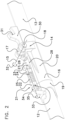
Figure 2 shows a perspective view of a locking device arranged on a rake member of the machine ofFigure 1 . - A machine for working grass, hay or other crops is generally denoted in
figure 1 by reference numeral 1. In this exemplary embodiment, the machine 1 is a rotary rake. The machine 1 comprises aframe 2 having afront end 3 configured to be connected to a pulling vehicle, for example a tractor, and arear end 4 provided withwheels 5 to support theframe 2. At each side of theframe 2, arake member arm 6 having a fixed length is provided. A trolley carrying arake member 7 can be displaced in a sliding manner along eachrake member arm 6. However, therake member arm 6 can be constructed in a different manner, for example as a telescopic arm. - Each
rake member 7 comprises acentre body 8 that is rotatably connected to the trolley on the respectiverake member arm 6. Multiple rake element arms ortine arms 9 are distributed about the circumference of thecentre body 8 and extend from thecentre body 8. At the distal ends of therake element arms 9rake elements 10, for example tines, are provided. - During use of the machine 1, when the
frame 2 is pulled in a direction of travel over a field on which grass, hay or other crops are present, therake members 7 are rotated about a substantially vertical axis of rotation of thecentre body 8. As a result, the crops on the field are displaced by therake elements 10 in order to arrange the crops in a desired configuration on the field. - The
rake member arms 6 and therake members 7 connected thereto are movable between a working position, in which therake element arms 9 extend in a substantially horizontal plane (as shown inFigure 1 ), and a transport position in which the rake elements arm extend in a more upright plane, for example in a substantially vertical plane.Hydraulic cylinders 11 are provided to actuate the movement of therake member arms 6 between the working position and the transport position. - When the machine is not used, it is desirable to bring the machine in a compact configuration. In particular for road transport, it is important that the machine does not exceed a maximum transport height. At the same time it is desirable that the working width during use, i.e. in the working position, is relatively large so that a wide strip of field can be handled by the machine 1.
- In order to avoid that the machine becomes too high during transport, according to the invention, at least some of the
rake element arms 9 comprise aninner arm part 12 and anouter arm part 13 that are pivotally connected to each other between a working position and a transport position. In the working position, the longitudinal axes of theinner arm part 12 and theouter arm part 13 of such a foldablerake element arm 9 coincide such that the configuration of the foldablerake element arms 9 in the working position substantially corresponds to the configuration of the other non-foldablerake element arms 9. - In the transport position, the
outer arm parts 13 may be arranged in a folded position with respect to theinner arm parts 12 such that the maximum radial distance of theouter arm parts 13 with respect to the axis of rotation of thecentre body 13 is smaller than the maximum radial distance of theouter arm parts 13 in the working position. This results in a reduced height of the machine 1, when therake members 7 are pivoted upwards to the transport position, and the foldedouter arms 13 are arranged at the upper side of the machine 1 in this transport position. The rotatedouter arm parts 13 may also result in a reduced width in transport position. - The
rake element arms 9 having aninner arm part 12 andouter arm part 13 that are hingeable with respect to each other comprise ahinge 14 and a locking device. Thehinge 14 and locking device are schematically indicated by boxes A infigure 1 . Thehinge 14 and the locking device are shown in more detail infigure 2 . - In
figure 2 , theinner arm part 12 and theouter arm part 13 are shown in the working position. Theinner arm part 12 and theouter arm part 13 are hingeable with respect to each other about ahinge 14 having ahinge axis 15. Thehinge 14 is formed by afirst hinge part 16 mounted on theinner arm part 12, asecond hinge part 17 mounted on theouter arm part 13, and also ahinge pin 18. - The
first hinge part 16 comprises acylindrical part 19 which is mounted on the end of theinner arm part 12, and a recessed, for example half-open,cylindrical part 20 which protrudes from the end of theinner arm part 12 and configured to receive an end part of theouter arm part 13, when theouter arm part 13 is arranged in the working position. When theouter arm part 13 is received in thecylindrical part 20, forces exerted on the rake element arm may be more efficiently transferred from theouter arm part 13 onto theinner arm part 12. At the end of thefirst hinge part 16 remote from the end of theinner arm part 16, hinge elements are provided having openings to receive thehinge pin 18. - On the
first hinge part 16, a lockingpin housing 21 is mounted. The lockingpin housing 21 comprises a first locking pin holder 22 and a secondlocking pin holder 23. Each of the first locking pin holder 22 and the secondlocking pin holder 23 comprises a locking pin receiving hole through which alocking pin 24 extends. The inner diameter of the locking pin receiving holes of the first and secondlocking pin holders 22, 23 substantially corresponds to the outer diameter of the lockingpin 24 such that the lockingpin 24 can slide in its longitudinal direction in thelocking pin housing 21 between a locking position and a non-locking or releasing position. The direction of the sliding movement is substantially parallel to the longitudinal direction of theinner arm part 12. The lockingpin 24 is biased by a coiled spring element 25 towards the locking position, e.g. in the shown embodiment towards thehinge pin 18. - On the
outer arm part 13, a first slot element 26 having a first slot 27 is mounted. Anopening 28 is provided in thefirst hinge part 16 to allow the slot element 26 through thefirst hinge part 16 in the position shown infigure 2 . In the working position, the slot element 26 is arranged on the part of theouter arm part 13 between thehinge pin 18 and the end of theouter arm part 13 which is, in the working position, adjacent to theinner arm part 12. At the opposite side of thehinge pin 18, asecond slot element 30 with aslot 31 is mounted on theouter arm part 13. - In the working position as shown in
figure 2 , the first slot 27 is aligned with the lockingpin 24. Since the lockingpin 24 is biased towards the locking position, the lockingpin 24 is pushed by the spring element 25 into the first slot 27. This results in the lockingpin 24 being reliably captured by the first slot 27 and, as a consequence, theinner arm part 12 and theouter arm part 13 are locked so as to remain aligned with respect to each other in the working position. - To release the locking
pin 24 from the first slot 27, the lockingpin 24 is moved against the biasing force of the spring element 25 towards the non-locking or releasing position, i.e. in this exemplary embodiment away from thehinge pin 18, until the lockingpin 24 is no longer received in the first slot 27. To facilitate this movement of the lockingpin 24 against the biasing force of the spring element 25, the lockingpin 24 is provided with acam 33 that protrudes from the circumferential outer surface of the lockingpin 24, and the first locking pin holder 22 is provided with acam surface 34. - The
cam surface 34 and thecam 33 are configured in such a manner that rotation of the lockingpin 24 about its longitudinal axis in the direction shown byarrow 35 will result in thecam 33 sliding along thecam surface 34 which is shaped such that the lockingpin 24 will be pushed due to the rotating movement of the lockingpin 24 towards the non-locking position. - The
cam surface 33 may be provided with an indent for receiving thecam 33 in the non-locking position so that the lockingpin 24 can be held by theindent 33 in said position, i.e. when the lockingpin 24 is accommodated in the indent it is prevented from being automatically pushed back to the locking position by the spring element 25. It is noted that such an indent is entirely optional. For example, in other embodiments, the biasing force of the spring element 25 may be insufficient to automatically push thelocking pin 24 back to the locking position. It is also noted that any other device to move the lockingpin 24 to the non-locking position may also be used. - When the locking pin 25 is held in the non-locking position, the
outer arm part 13 can be pivoted with respect to theinner arm part 12 in the direction of thearrow 32. With this pivotal movement, thesecond slot 31 can be aligned with the lockingpin 24. When thesecond slot 31 and the lockingpin 24 are aligned, the lockingpin 24 can be displaced back, i.e. such that the spring element 25 will move the lockingpin 24 towards the locking position and therewith into thesecond slot 31. This results in the lockingpin 24 being reliably secured inside thesecond slot 31 and, as a consequence, theinner arm part 12 and theouter arm part 13 are held in the transport position. - Thus, a
single locking pin 24 is used to cooperate both with a first slot 27 to lock theouter arm part 13 with respect to theinner arm part 12 in the working position and with asecond slot 31 to lock theouter arm part 13 with respect to theinner arm part 12 in the transport position. - The locking
pin housing 21 and the lockingpin 24 are designed such that the lockingpin 24 can extend further towards the locking position than required to fully enter the first slot 27. This has the advantage that wear at the end of the lockingpin 24 and/or wear in the first slot 27 does not result in play between the lockingpin 24 and the first slot 27. Correspondingly, the lockingpin housing 21 and the lockingpin 24 may also be designed such that the lockingpin 24 can extend further towards the locking position than required to fully enter thesecond slot 31 so that wear at the end of the lockingpin 24 and/or wear in thesecond slot 31 does not result in play between the lockingpin 24 and thesecond slot 31.
Claims (8)
- A tine arm (9) for an agricultural machine (1) for working grass, hay or other crops on the field, wherein one or more tines (10) are mounted on the time arm, the tine arm comprising:- a first arm part (12) and a second arm part (13) which are pivotally connected to each other between a working position and a transport position, and- a locking device configured to lock the first arm part (12) with respect to the second arm part (13) in the working position,wherein the locking device comprises:- a locking pin (24) movably mounted on the first arm part (12) between a locking position and a non-locking or releasing position, and- a first slot (27) and second slot (31) which are mounted on the second arm part (13), wherein the first slot (27) is arranged to receive the locking pin (24) in the locking position when the first arm part (12) and the second arm part (13) are positioned in the working position to lock the first arm part (12) with respect to the second arm part (13) in the working position, and wherein the second slot (31) is arranged to receive the locking pin (24) in the locking position when the first arm part (12) and the second arm part (13) are positioned in the transport position to lock the first arm part (12) with respect to the second arm part (13) in the transport position,wherein the locking device comprises a locking pin housing (21) configured to receive the locking pin (24),wherein the locking pin (24) is rotatable about its longitudinal axis, wherein the locking pin (24) comprises a cam (33) extending at least partially transversely to the longitudinal axis of the locking pin (24) and wherein the locking pin housing (21) comprises a cam surface (34) configured to cooperate with the cam (33) such that by rotation of the locking pin (24) about its longitudinal axis the cam (33) moves along the cam surface (34) so as to move the locking pin (24) from its locking position towards its non-locking position and/or from the non-locking position towards the locking position,characterised in that the locking pin housing (21) comprises two spaced locking pin holders (22, 23), each locking pin holder (22, 23) having a locking pin receiving hole with an inner diameter substantially corresponding to an outer diameter of the locking pin (24), wherein at least one of the locking pin holders (22, 23) comprises the cam surface (34).
- The tine arm (9) of claim 1, wherein the locking device comprises a hinge (14) that hingeably connects the first arm part (12) to the second arm part (13), wherein the hinge comprises a first hinge part (16) mounted on the first arm part (12) and a second hinge part (17) mounted on the second arm part (13).
- The tine arm (9) of claim 2, wherein the hinge (14) comprises a hinge axis (15) which is arranged at a position spaced from the end of the second arm part (13), wherein the first slot (27) is mounted on the second arm part (13) at a first side of the hinge axis (15), and wherein the second slot (31) is mounted on the second arm part (13) at a second side of the hinge axis (15) opposite to the first side.
- The tine arm (9) of claim 2 or 3, wherein the locking pin (24) is movably mounted on the first hinge part (16).
- The tine arm (9) of any of the claims 2-4, wherein the first hinge part (16) comprises a cylindrical part (19) configured to be mounted on the end of the first arm part (12), and a recessed cylindrical part (20) configured to receive a part of the second arm part (13) in the working position.
- The tine arm (9) of any of the claims 1-5, wherein the locking pin (24) is biased towards the locking position.
- The tine arm (9) of claim 6, wherein the locking pin (24) is biased towards the locking position by a spring element (25).
- The tine arm (9) of any of the claims 1-7, wherein the locking pin (24) is movable with respect to the first arm part (12) in a direction substantially parallel to a longitudinal direction of the first arm part (12).
Applications Claiming Priority (2)
| Application Number | Priority Date | Filing Date | Title |
|---|---|---|---|
| NL2015036A NL2015036B1 (en) | 2015-06-26 | 2015-06-26 | An agricultural machine for working grass, hay or other crops, as well as a raking member. |
| EP16175544.2A EP3108740B1 (en) | 2015-06-26 | 2016-06-21 | A rake element arm for an agricultural machine for working grass, hay or other crops, as well as such an agricultural machine |
Related Parent Applications (3)
| Application Number | Title | Priority Date | Filing Date |
|---|---|---|---|
| EP16175544.2A Division EP3108740B1 (en) | 2015-06-26 | 2016-06-21 | A rake element arm for an agricultural machine for working grass, hay or other crops, as well as such an agricultural machine |
| EP16175544.2A Previously-Filed-Application EP3108740B1 (en) | 2015-06-26 | 2016-06-21 | A rake element arm for an agricultural machine for working grass, hay or other crops, as well as such an agricultural machine |
| EP16175544.2A Division-Into EP3108740B1 (en) | 2015-06-26 | 2016-06-21 | A rake element arm for an agricultural machine for working grass, hay or other crops, as well as such an agricultural machine |
Publications (2)
| Publication Number | Publication Date |
|---|---|
| EP3750395A1 EP3750395A1 (en) | 2020-12-16 |
| EP3750395B1 true EP3750395B1 (en) | 2023-05-03 |
Family
ID=53783870
Family Applications (2)
| Application Number | Title | Priority Date | Filing Date |
|---|---|---|---|
| EP20184315.8A Active EP3750395B1 (en) | 2015-06-26 | 2016-06-21 | A tine arm for an agricultural machine for working grass, hay or other crops |
| EP16175544.2A Active EP3108740B1 (en) | 2015-06-26 | 2016-06-21 | A rake element arm for an agricultural machine for working grass, hay or other crops, as well as such an agricultural machine |
Family Applications After (1)
| Application Number | Title | Priority Date | Filing Date |
|---|---|---|---|
| EP16175544.2A Active EP3108740B1 (en) | 2015-06-26 | 2016-06-21 | A rake element arm for an agricultural machine for working grass, hay or other crops, as well as such an agricultural machine |
Country Status (2)
| Country | Link |
|---|---|
| EP (2) | EP3750395B1 (en) |
| NL (1) | NL2015036B1 (en) |
Family Cites Families (5)
| Publication number | Priority date | Publication date | Assignee | Title |
|---|---|---|---|---|
| DE1907226U (en) * | 1964-07-24 | 1964-12-23 | Josef Bautz G M B H | TINE BASKET FOR ROTARY TEDERS. |
| DE1266556B (en) * | 1966-06-24 | 1968-04-18 | Fahr Ag Maschf | Articulated connection between the sections of a cardan shaft provided with support tubes |
| NL6610784A (en) * | 1966-08-01 | 1968-02-02 | Lely Nv C Van Der | DEVICE FOR TREATING GROUND CROP |
| AT298135B (en) * | 1969-05-22 | 1972-04-25 | Poettinger Ohg Alois | Rotary swath rake |
| DE20207643U1 (en) * | 2002-05-14 | 2002-08-22 | Maschinenfabrik Bernard Krone GmbH, 48480 Spelle | Rotary rake for a haymaking machine |
-
2015
- 2015-06-26 NL NL2015036A patent/NL2015036B1/en not_active IP Right Cessation
-
2016
- 2016-06-21 EP EP20184315.8A patent/EP3750395B1/en active Active
- 2016-06-21 EP EP16175544.2A patent/EP3108740B1/en active Active
Also Published As
| Publication number | Publication date |
|---|---|
| EP3108740A1 (en) | 2016-12-28 |
| EP3108740B1 (en) | 2021-02-24 |
| NL2015036B1 (en) | 2017-01-24 |
| EP3750395A1 (en) | 2020-12-16 |
Similar Documents
| Publication | Publication Date | Title |
|---|---|---|
| US7849933B2 (en) | Bifold transport lock | |
| US9475538B2 (en) | Foldable riding vehicle | |
| US8235133B2 (en) | Agricultural implement having wheels that caster | |
| EP2992749B1 (en) | Windrow shield control system for a header of an agricultural harvester | |
| EP2306804B1 (en) | Adjustable and foldable v-shaped hay rake | |
| CA2665257A1 (en) | Agricultural implement having forward folding wing booms | |
| US20160050838A1 (en) | Toolbar system for an agricultural implement | |
| EP3231274B1 (en) | Accumulator | |
| US9468138B2 (en) | Implement for a tractor hitch | |
| EP3231273B1 (en) | Accumulator | |
| US8261846B2 (en) | Implement support stand | |
| US4632417A (en) | Bi-fold hinge for a folding toolbar | |
| WO2015124843A1 (en) | Canopy structure, in particular for a loading platform, such as a truck flatbed, trailer flatbed or the like, and canopy incorporating such a structure | |
| US9788471B2 (en) | Link assembly | |
| US9282694B2 (en) | Articulated garden rake | |
| EP3108740B1 (en) | A rake element arm for an agricultural machine for working grass, hay or other crops, as well as such an agricultural machine | |
| CN102762092B (en) | Wheel assembly | |
| US5875625A (en) | Fruit catcher | |
| FR3023675A1 (en) | HARVESTING DEVICE COUPLABLE TO A HARVESTING MACHINE, AND ASSEMBLY COMPRISING THE DEVICE AND THE MACHINE | |
| EP2805593B1 (en) | Device unit with a position securing device | |
| US10568264B2 (en) | Harvester with header lift assembly | |
| NL1034861C2 (en) | Hay collection machine. | |
| DK2526758T3 (en) | Mower | |
| US10051775B2 (en) | Frame latch system | |
| JP6251138B2 (en) | Foldable twin rake |
Legal Events
| Date | Code | Title | Description |
|---|---|---|---|
| PUAI | Public reference made under article 153(3) epc to a published international application that has entered the european phase |
Free format text: ORIGINAL CODE: 0009012 |
|
| STAA | Information on the status of an ep patent application or granted ep patent |
Free format text: STATUS: THE APPLICATION HAS BEEN PUBLISHED |
|
| AC | Divisional application: reference to earlier application |
Ref document number: 3108740 Country of ref document: EP Kind code of ref document: P |
|
| AK | Designated contracting states |
Kind code of ref document: A1 Designated state(s): AL AT BE BG CH CY CZ DE DK EE ES FI FR GB GR HR HU IE IS IT LI LT LU LV MC MK MT NL NO PL PT RO RS SE SI SK SM TR |
|
| STAA | Information on the status of an ep patent application or granted ep patent |
Free format text: STATUS: REQUEST FOR EXAMINATION WAS MADE |
|
| 17P | Request for examination filed |
Effective date: 20210616 |
|
| RBV | Designated contracting states (corrected) |
Designated state(s): AL AT BE BG CH CY CZ DE DK EE ES FI FR GB GR HR HU IE IS IT LI LT LU LV MC MK MT NL NO PL PT RO RS SE SI SK SM TR |
|
| RAP3 | Party data changed (applicant data changed or rights of an application transferred) |
Owner name: FORAGE COMPANY B.V. |
|
| GRAP | Despatch of communication of intention to grant a patent |
Free format text: ORIGINAL CODE: EPIDOSNIGR1 |
|
| STAA | Information on the status of an ep patent application or granted ep patent |
Free format text: STATUS: GRANT OF PATENT IS INTENDED |
|
| RIC1 | Information provided on ipc code assigned before grant |
Ipc: A01D 78/10 19800101AFI20230109BHEP |
|
| INTG | Intention to grant announced |
Effective date: 20230209 |
|
| GRAS | Grant fee paid |
Free format text: ORIGINAL CODE: EPIDOSNIGR3 |
|
| GRAA | (expected) grant |
Free format text: ORIGINAL CODE: 0009210 |
|
| STAA | Information on the status of an ep patent application or granted ep patent |
Free format text: STATUS: THE PATENT HAS BEEN GRANTED |
|
| AC | Divisional application: reference to earlier application |
Ref document number: 3108740 Country of ref document: EP Kind code of ref document: P |
|
| AK | Designated contracting states |
Kind code of ref document: B1 Designated state(s): AL AT BE BG CH CY CZ DE DK EE ES FI FR GB GR HR HU IE IS IT LI LT LU LV MC MK MT NL NO PL PT RO RS SE SI SK SM TR |
|
| REG | Reference to a national code |
Ref country code: GB Ref legal event code: FG4D |
|
| REG | Reference to a national code |
Ref country code: DE Ref legal event code: R096 Ref document number: 602016079265 Country of ref document: DE |
|
| REG | Reference to a national code |
Ref country code: AT Ref legal event code: REF Ref document number: 1563820 Country of ref document: AT Kind code of ref document: T Effective date: 20230515 Ref country code: CH Ref legal event code: EP |
|
| REG | Reference to a national code |
Ref country code: IE Ref legal event code: FG4D |
|
| REG | Reference to a national code |
Ref country code: LT Ref legal event code: MG9D |
|
| REG | Reference to a national code |
Ref country code: NL Ref legal event code: MP Effective date: 20230503 |
|
| REG | Reference to a national code |
Ref country code: AT Ref legal event code: MK05 Ref document number: 1563820 Country of ref document: AT Kind code of ref document: T Effective date: 20230503 |
|
| PG25 | Lapsed in a contracting state [announced via postgrant information from national office to epo] |
Ref country code: SE Free format text: LAPSE BECAUSE OF FAILURE TO SUBMIT A TRANSLATION OF THE DESCRIPTION OR TO PAY THE FEE WITHIN THE PRESCRIBED TIME-LIMIT Effective date: 20230503 Ref country code: PT Free format text: LAPSE BECAUSE OF FAILURE TO SUBMIT A TRANSLATION OF THE DESCRIPTION OR TO PAY THE FEE WITHIN THE PRESCRIBED TIME-LIMIT Effective date: 20230904 Ref country code: NO Free format text: LAPSE BECAUSE OF FAILURE TO SUBMIT A TRANSLATION OF THE DESCRIPTION OR TO PAY THE FEE WITHIN THE PRESCRIBED TIME-LIMIT Effective date: 20230803 Ref country code: NL Free format text: LAPSE BECAUSE OF FAILURE TO SUBMIT A TRANSLATION OF THE DESCRIPTION OR TO PAY THE FEE WITHIN THE PRESCRIBED TIME-LIMIT Effective date: 20230503 Ref country code: ES Free format text: LAPSE BECAUSE OF FAILURE TO SUBMIT A TRANSLATION OF THE DESCRIPTION OR TO PAY THE FEE WITHIN THE PRESCRIBED TIME-LIMIT Effective date: 20230503 Ref country code: AT Free format text: LAPSE BECAUSE OF FAILURE TO SUBMIT A TRANSLATION OF THE DESCRIPTION OR TO PAY THE FEE WITHIN THE PRESCRIBED TIME-LIMIT Effective date: 20230503 |
|
| PG25 | Lapsed in a contracting state [announced via postgrant information from national office to epo] |
Ref country code: RS Free format text: LAPSE BECAUSE OF FAILURE TO SUBMIT A TRANSLATION OF THE DESCRIPTION OR TO PAY THE FEE WITHIN THE PRESCRIBED TIME-LIMIT Effective date: 20230503 Ref country code: PL Free format text: LAPSE BECAUSE OF FAILURE TO SUBMIT A TRANSLATION OF THE DESCRIPTION OR TO PAY THE FEE WITHIN THE PRESCRIBED TIME-LIMIT Effective date: 20230503 Ref country code: LV Free format text: LAPSE BECAUSE OF FAILURE TO SUBMIT A TRANSLATION OF THE DESCRIPTION OR TO PAY THE FEE WITHIN THE PRESCRIBED TIME-LIMIT Effective date: 20230503 Ref country code: LT Free format text: LAPSE BECAUSE OF FAILURE TO SUBMIT A TRANSLATION OF THE DESCRIPTION OR TO PAY THE FEE WITHIN THE PRESCRIBED TIME-LIMIT Effective date: 20230503 Ref country code: IS Free format text: LAPSE BECAUSE OF FAILURE TO SUBMIT A TRANSLATION OF THE DESCRIPTION OR TO PAY THE FEE WITHIN THE PRESCRIBED TIME-LIMIT Effective date: 20230903 Ref country code: HR Free format text: LAPSE BECAUSE OF FAILURE TO SUBMIT A TRANSLATION OF THE DESCRIPTION OR TO PAY THE FEE WITHIN THE PRESCRIBED TIME-LIMIT Effective date: 20230503 Ref country code: GR Free format text: LAPSE BECAUSE OF FAILURE TO SUBMIT A TRANSLATION OF THE DESCRIPTION OR TO PAY THE FEE WITHIN THE PRESCRIBED TIME-LIMIT Effective date: 20230804 |
|
| PG25 | Lapsed in a contracting state [announced via postgrant information from national office to epo] |
Ref country code: FI Free format text: LAPSE BECAUSE OF FAILURE TO SUBMIT A TRANSLATION OF THE DESCRIPTION OR TO PAY THE FEE WITHIN THE PRESCRIBED TIME-LIMIT Effective date: 20230503 |
|
| PG25 | Lapsed in a contracting state [announced via postgrant information from national office to epo] |
Ref country code: SK Free format text: LAPSE BECAUSE OF FAILURE TO SUBMIT A TRANSLATION OF THE DESCRIPTION OR TO PAY THE FEE WITHIN THE PRESCRIBED TIME-LIMIT Effective date: 20230503 |
|
| PG25 | Lapsed in a contracting state [announced via postgrant information from national office to epo] |
Ref country code: SM Free format text: LAPSE BECAUSE OF FAILURE TO SUBMIT A TRANSLATION OF THE DESCRIPTION OR TO PAY THE FEE WITHIN THE PRESCRIBED TIME-LIMIT Effective date: 20230503 Ref country code: SK Free format text: LAPSE BECAUSE OF FAILURE TO SUBMIT A TRANSLATION OF THE DESCRIPTION OR TO PAY THE FEE WITHIN THE PRESCRIBED TIME-LIMIT Effective date: 20230503 Ref country code: RO Free format text: LAPSE BECAUSE OF FAILURE TO SUBMIT A TRANSLATION OF THE DESCRIPTION OR TO PAY THE FEE WITHIN THE PRESCRIBED TIME-LIMIT Effective date: 20230503 Ref country code: EE Free format text: LAPSE BECAUSE OF FAILURE TO SUBMIT A TRANSLATION OF THE DESCRIPTION OR TO PAY THE FEE WITHIN THE PRESCRIBED TIME-LIMIT Effective date: 20230503 Ref country code: DK Free format text: LAPSE BECAUSE OF FAILURE TO SUBMIT A TRANSLATION OF THE DESCRIPTION OR TO PAY THE FEE WITHIN THE PRESCRIBED TIME-LIMIT Effective date: 20230503 Ref country code: CZ Free format text: LAPSE BECAUSE OF FAILURE TO SUBMIT A TRANSLATION OF THE DESCRIPTION OR TO PAY THE FEE WITHIN THE PRESCRIBED TIME-LIMIT Effective date: 20230503 |
|
| REG | Reference to a national code |
Ref country code: CH Ref legal event code: PL |
|
| REG | Reference to a national code |
Ref country code: DE Ref legal event code: R097 Ref document number: 602016079265 Country of ref document: DE |
|
| REG | Reference to a national code |
Ref country code: BE Ref legal event code: MM Effective date: 20230630 |
|
| PG25 | Lapsed in a contracting state [announced via postgrant information from national office to epo] |
Ref country code: MC Free format text: LAPSE BECAUSE OF FAILURE TO SUBMIT A TRANSLATION OF THE DESCRIPTION OR TO PAY THE FEE WITHIN THE PRESCRIBED TIME-LIMIT Effective date: 20230503 |
|
| PG25 | Lapsed in a contracting state [announced via postgrant information from national office to epo] |
Ref country code: MC Free format text: LAPSE BECAUSE OF FAILURE TO SUBMIT A TRANSLATION OF THE DESCRIPTION OR TO PAY THE FEE WITHIN THE PRESCRIBED TIME-LIMIT Effective date: 20230503 |
|
| PG25 | Lapsed in a contracting state [announced via postgrant information from national office to epo] |
Ref country code: LU Free format text: LAPSE BECAUSE OF NON-PAYMENT OF DUE FEES Effective date: 20230621 |
|
| PLBE | No opposition filed within time limit |
Free format text: ORIGINAL CODE: 0009261 |
|
| STAA | Information on the status of an ep patent application or granted ep patent |
Free format text: STATUS: NO OPPOSITION FILED WITHIN TIME LIMIT |
|
| REG | Reference to a national code |
Ref country code: IE Ref legal event code: MM4A |
|
| PG25 | Lapsed in a contracting state [announced via postgrant information from national office to epo] |
Ref country code: LU Free format text: LAPSE BECAUSE OF NON-PAYMENT OF DUE FEES Effective date: 20230621 |
|
| 26N | No opposition filed |
Effective date: 20240206 |
|
| PG25 | Lapsed in a contracting state [announced via postgrant information from national office to epo] |
Ref country code: IE Free format text: LAPSE BECAUSE OF NON-PAYMENT OF DUE FEES Effective date: 20230621 |
|
| GBPC | Gb: european patent ceased through non-payment of renewal fee |
Effective date: 20230803 |
|
| PG25 | Lapsed in a contracting state [announced via postgrant information from national office to epo] |
Ref country code: IE Free format text: LAPSE BECAUSE OF NON-PAYMENT OF DUE FEES Effective date: 20230621 Ref country code: CH Free format text: LAPSE BECAUSE OF NON-PAYMENT OF DUE FEES Effective date: 20230630 |
|
| PG25 | Lapsed in a contracting state [announced via postgrant information from national office to epo] |
Ref country code: SI Free format text: LAPSE BECAUSE OF FAILURE TO SUBMIT A TRANSLATION OF THE DESCRIPTION OR TO PAY THE FEE WITHIN THE PRESCRIBED TIME-LIMIT Effective date: 20230503 |
|
| PG25 | Lapsed in a contracting state [announced via postgrant information from national office to epo] |
Ref country code: SI Free format text: LAPSE BECAUSE OF FAILURE TO SUBMIT A TRANSLATION OF THE DESCRIPTION OR TO PAY THE FEE WITHIN THE PRESCRIBED TIME-LIMIT Effective date: 20230503 Ref country code: IT Free format text: LAPSE BECAUSE OF FAILURE TO SUBMIT A TRANSLATION OF THE DESCRIPTION OR TO PAY THE FEE WITHIN THE PRESCRIBED TIME-LIMIT Effective date: 20230503 Ref country code: BE Free format text: LAPSE BECAUSE OF NON-PAYMENT OF DUE FEES Effective date: 20230630 |
|
| PG25 | Lapsed in a contracting state [announced via postgrant information from national office to epo] |
Ref country code: GB Free format text: LAPSE BECAUSE OF NON-PAYMENT OF DUE FEES Effective date: 20230803 |
|
| PG25 | Lapsed in a contracting state [announced via postgrant information from national office to epo] |
Ref country code: GB Free format text: LAPSE BECAUSE OF NON-PAYMENT OF DUE FEES Effective date: 20230803 |
|
| PG25 | Lapsed in a contracting state [announced via postgrant information from national office to epo] |
Ref country code: BG Free format text: LAPSE BECAUSE OF FAILURE TO SUBMIT A TRANSLATION OF THE DESCRIPTION OR TO PAY THE FEE WITHIN THE PRESCRIBED TIME-LIMIT Effective date: 20230503 |
|
| PG25 | Lapsed in a contracting state [announced via postgrant information from national office to epo] |
Ref country code: BG Free format text: LAPSE BECAUSE OF FAILURE TO SUBMIT A TRANSLATION OF THE DESCRIPTION OR TO PAY THE FEE WITHIN THE PRESCRIBED TIME-LIMIT Effective date: 20230503 |
|
| PGFP | Annual fee paid to national office [announced via postgrant information from national office to epo] |
Ref country code: DE Payment date: 20250618 Year of fee payment: 10 |
|
| PGFP | Annual fee paid to national office [announced via postgrant information from national office to epo] |
Ref country code: FR Payment date: 20250626 Year of fee payment: 10 |
|
| PG25 | Lapsed in a contracting state [announced via postgrant information from national office to epo] |
Ref country code: CY Free format text: LAPSE BECAUSE OF FAILURE TO SUBMIT A TRANSLATION OF THE DESCRIPTION OR TO PAY THE FEE WITHIN THE PRESCRIBED TIME-LIMIT; INVALID AB INITIO Effective date: 20160621 |
|
| PG25 | Lapsed in a contracting state [announced via postgrant information from national office to epo] |
Ref country code: HU Free format text: LAPSE BECAUSE OF FAILURE TO SUBMIT A TRANSLATION OF THE DESCRIPTION OR TO PAY THE FEE WITHIN THE PRESCRIBED TIME-LIMIT; INVALID AB INITIO Effective date: 20160621 |
|
| PG25 | Lapsed in a contracting state [announced via postgrant information from national office to epo] |
Ref country code: TR Free format text: LAPSE BECAUSE OF FAILURE TO SUBMIT A TRANSLATION OF THE DESCRIPTION OR TO PAY THE FEE WITHIN THE PRESCRIBED TIME-LIMIT Effective date: 20230503 |