EP3749985B1 - Systems and methods for digital x-ray imaging - Google Patents
Systems and methods for digital x-ray imaging Download PDFInfo
- Publication number
- EP3749985B1 EP3749985B1 EP19706218.5A EP19706218A EP3749985B1 EP 3749985 B1 EP3749985 B1 EP 3749985B1 EP 19706218 A EP19706218 A EP 19706218A EP 3749985 B1 EP3749985 B1 EP 3749985B1
- Authority
- EP
- European Patent Office
- Prior art keywords
- ray
- digital
- portable
- scanner
- computing device
- Prior art date
- Legal status (The legal status is an assumption and is not a legal conclusion. Google has not performed a legal analysis and makes no representation as to the accuracy of the status listed.)
- Active
Links
Images





Classifications
-
- A—HUMAN NECESSITIES
- A61—MEDICAL OR VETERINARY SCIENCE; HYGIENE
- A61B—DIAGNOSIS; SURGERY; IDENTIFICATION
- A61B6/00—Apparatus or devices for radiation diagnosis; Apparatus or devices for radiation diagnosis combined with radiation therapy equipment
- A61B6/44—Constructional features of apparatus for radiation diagnosis
- A61B6/4405—Constructional features of apparatus for radiation diagnosis the apparatus being movable or portable, e.g. handheld or mounted on a trolley
-
- A—HUMAN NECESSITIES
- A61—MEDICAL OR VETERINARY SCIENCE; HYGIENE
- A61B—DIAGNOSIS; SURGERY; IDENTIFICATION
- A61B6/00—Apparatus or devices for radiation diagnosis; Apparatus or devices for radiation diagnosis combined with radiation therapy equipment
- A61B6/06—Diaphragms
-
- A—HUMAN NECESSITIES
- A61—MEDICAL OR VETERINARY SCIENCE; HYGIENE
- A61B—DIAGNOSIS; SURGERY; IDENTIFICATION
- A61B6/00—Apparatus or devices for radiation diagnosis; Apparatus or devices for radiation diagnosis combined with radiation therapy equipment
- A61B6/10—Safety means specially adapted therefor
- A61B6/107—Protection against radiation, e.g. shielding
-
- A—HUMAN NECESSITIES
- A61—MEDICAL OR VETERINARY SCIENCE; HYGIENE
- A61B—DIAGNOSIS; SURGERY; IDENTIFICATION
- A61B6/00—Apparatus or devices for radiation diagnosis; Apparatus or devices for radiation diagnosis combined with radiation therapy equipment
- A61B6/40—Arrangements for generating radiation specially adapted for radiation diagnosis
- A61B6/405—Source units specially adapted to modify characteristics of the beam during the data acquisition process
-
- A—HUMAN NECESSITIES
- A61—MEDICAL OR VETERINARY SCIENCE; HYGIENE
- A61B—DIAGNOSIS; SURGERY; IDENTIFICATION
- A61B6/00—Apparatus or devices for radiation diagnosis; Apparatus or devices for radiation diagnosis combined with radiation therapy equipment
- A61B6/44—Constructional features of apparatus for radiation diagnosis
- A61B6/4429—Constructional features of apparatus for radiation diagnosis related to the mounting of source units and detector units
- A61B6/4435—Constructional features of apparatus for radiation diagnosis related to the mounting of source units and detector units the source unit and the detector unit being coupled by a rigid structure
- A61B6/4441—Constructional features of apparatus for radiation diagnosis related to the mounting of source units and detector units the source unit and the detector unit being coupled by a rigid structure the rigid structure being a C-arm or U-arm
-
- A—HUMAN NECESSITIES
- A61—MEDICAL OR VETERINARY SCIENCE; HYGIENE
- A61B—DIAGNOSIS; SURGERY; IDENTIFICATION
- A61B6/00—Apparatus or devices for radiation diagnosis; Apparatus or devices for radiation diagnosis combined with radiation therapy equipment
- A61B6/46—Arrangements for interfacing with the operator or the patient
- A61B6/467—Arrangements for interfacing with the operator or the patient characterised by special input means
-
- A—HUMAN NECESSITIES
- A61—MEDICAL OR VETERINARY SCIENCE; HYGIENE
- A61B—DIAGNOSIS; SURGERY; IDENTIFICATION
- A61B6/00—Apparatus or devices for radiation diagnosis; Apparatus or devices for radiation diagnosis combined with radiation therapy equipment
- A61B6/48—Diagnostic techniques
- A61B6/486—Diagnostic techniques involving generating temporal series of image data
- A61B6/487—Diagnostic techniques involving generating temporal series of image data involving fluoroscopy
-
- A—HUMAN NECESSITIES
- A61—MEDICAL OR VETERINARY SCIENCE; HYGIENE
- A61B—DIAGNOSIS; SURGERY; IDENTIFICATION
- A61B6/00—Apparatus or devices for radiation diagnosis; Apparatus or devices for radiation diagnosis combined with radiation therapy equipment
- A61B6/54—Control of apparatus or devices for radiation diagnosis
-
- A—HUMAN NECESSITIES
- A61—MEDICAL OR VETERINARY SCIENCE; HYGIENE
- A61B—DIAGNOSIS; SURGERY; IDENTIFICATION
- A61B6/00—Apparatus or devices for radiation diagnosis; Apparatus or devices for radiation diagnosis combined with radiation therapy equipment
- A61B6/56—Details of data transmission or power supply, e.g. use of slip rings
-
- G—PHYSICS
- G01—MEASURING; TESTING
- G01T—MEASUREMENT OF NUCLEAR OR X-RADIATION
- G01T1/00—Measuring X-radiation, gamma radiation, corpuscular radiation, or cosmic radiation
- G01T1/16—Measuring radiation intensity
- G01T1/20—Measuring radiation intensity with scintillation detectors
-
- G—PHYSICS
- G01—MEASURING; TESTING
- G01T—MEASUREMENT OF NUCLEAR OR X-RADIATION
- G01T1/00—Measuring X-radiation, gamma radiation, corpuscular radiation, or cosmic radiation
- G01T1/16—Measuring radiation intensity
- G01T1/20—Measuring radiation intensity with scintillation detectors
- G01T1/2002—Optical details, e.g. reflecting or diffusing layers
-
- G—PHYSICS
- G01—MEASURING; TESTING
- G01T—MEASUREMENT OF NUCLEAR OR X-RADIATION
- G01T1/00—Measuring X-radiation, gamma radiation, corpuscular radiation, or cosmic radiation
- G01T1/16—Measuring radiation intensity
- G01T1/20—Measuring radiation intensity with scintillation detectors
- G01T1/2018—Scintillation-photodiode combinations
-
- G—PHYSICS
- G01—MEASURING; TESTING
- G01T—MEASUREMENT OF NUCLEAR OR X-RADIATION
- G01T1/00—Measuring X-radiation, gamma radiation, corpuscular radiation, or cosmic radiation
- G01T1/16—Measuring radiation intensity
- G01T1/24—Measuring radiation intensity with semiconductor detectors
-
- G—PHYSICS
- G01—MEASURING; TESTING
- G01T—MEASUREMENT OF NUCLEAR OR X-RADIATION
- G01T7/00—Details of radiation-measuring instruments
-
- G—PHYSICS
- G21—NUCLEAR PHYSICS; NUCLEAR ENGINEERING
- G21F—PROTECTION AGAINST X-RADIATION, GAMMA RADIATION, CORPUSCULAR RADIATION OR PARTICLE BOMBARDMENT; TREATING RADIOACTIVELY CONTAMINATED MATERIAL; DECONTAMINATION ARRANGEMENTS THEREFOR
- G21F1/00—Shielding characterised by the composition of the materials
- G21F1/02—Selection of uniform shielding materials
- G21F1/08—Metals; Alloys; Cermets, i.e. sintered mixtures of ceramics and metals
- G21F1/085—Heavy metals or alloys
-
- H—ELECTRICITY
- H01—ELECTRIC ELEMENTS
- H01J—ELECTRIC DISCHARGE TUBES OR DISCHARGE LAMPS
- H01J35/00—X-ray tubes
- H01J35/02—Details
-
- H—ELECTRICITY
- H04—ELECTRIC COMMUNICATION TECHNIQUE
- H04N—PICTORIAL COMMUNICATION, e.g. TELEVISION
- H04N5/00—Details of television systems
- H04N5/30—Transforming light or analogous information into electric information
- H04N5/32—Transforming X-rays
- H04N5/321—Transforming X-rays with video transmission of fluoroscopic images
-
- A—HUMAN NECESSITIES
- A61—MEDICAL OR VETERINARY SCIENCE; HYGIENE
- A61B—DIAGNOSIS; SURGERY; IDENTIFICATION
- A61B6/00—Apparatus or devices for radiation diagnosis; Apparatus or devices for radiation diagnosis combined with radiation therapy equipment
- A61B6/40—Arrangements for generating radiation specially adapted for radiation diagnosis
- A61B6/4035—Arrangements for generating radiation specially adapted for radiation diagnosis the source being combined with a filter or grating
Definitions
- WO2016172611A1 discloses a portable X-ray device with a C-shaped support arm with an X-ray source on one end and an X-ray detector on the other end.
- WO2014022217A1 discloses a hand-held imaging device with a radiation source and detector fixed by a frame.
- WO2005081956A2 discloses an X-ray device with a housing containing an X-ray tube, power system and an X-ray sensor.
- US2012148031A1 discloses a fluoroscopic imaging system with a support carrying an X-ray source and an X-ray detector.
- Disclosed example handheld X-ray imaging systems enable real-time generation and/or display of digital images during X-ray radiography.
- disclosed examples provide an all-in-one X-ray radiography unit that does not require extraneous equipment for power, X-ray generation, radiograph capture, radiograph display, or radiograph storage.
- Disclosed example handheld X-ray imaging systems reduce operator fatigue relative to conventional scanning devices by having a reduced weight, e.g. less than 20 pounds (9 kg), and/or by providing improved weight distribution that concentrates the weight of the handheld X-ray imaging system near the operator's body.
- real-time refers to the actual time elapsed in the performance of a computation by a computing device, the result of the computation being required for the continuation of a physical process (i.e., no significant delays are introduced).
- real-time display of captured images includes processing captured image data and displaying the resulting output images to create the perception to a user that the images are displayed immediately upon capture.
- portable includes handheld (e.g., capable of being carried and operated by a single person) and/or wheeled (e.g., capable of being transported and operated while wheels are attached and/or placed on wheels).
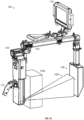
- FIG. 1 is a perspective view of an example handheld X-ray imaging system 100 to generate and output digital images and/or video based on incident X-rays.
- the example handheld X-ray imaging system 100 may be used to perform non-destructive testing (NDT), medical scanning, security scanning, and/or any other scanning application.
- NDT non-destructive testing
- the system 100 of FIG. 1 includes a frame 102 that holds an X-ray generator 104 and an X-ray detector 106.
- the frame 102 is C-shaped, such that the X-ray generator 104 directs X-ray radiation toward the X-ray detector 106.
- the frame 102 is positionable (e.g., held by an operator, supported by an external support structure and/or manipulated by the operator, etc.) around an object to be scanned with X-rays.
- the example frame 102 is constructed using carbon fiber and/or machined aluminum.
- the X-ray generator 104 is located on a first section 108 of the C-shaped frame 102 generates and outputs X-ray radiation, which traverses and/or scatters based on the state of the object under test.
- the X-ray detector 106 is located on a second section 110 of the frame 102 (e.g., opposite the first section 108) and receives incident radiation generated by the X-ray generator 104.
- the example frame 102 may be manipulated using one or more handles 112, 114.
- a first one of the handles 114 is adjustable and may be secured to provide the operator with leverage to manipulate the frame 102.
- the example handle 114 may be oriented with multiple degrees of freedom and/or adjusted along a length of a central section 116 of the frame 102.
- a second one of the handles 112 is an operator control handle, and enables an operator to both mechanically manipulate the frame 102 and control the operation of the handheld X-ray imaging system 100.
- the handheld X-ray imaging system 100 generates digital images (e.g., digital video and/or digital still images) from the X-ray radiation.
- the handheld X-ray imaging system 100 may store the digital images on one or more storage devices, display the digital images on a display device 118, and/or transmit the digital images to a remote receiver.
- the example display device 118 is attachable to the example frame 102 and/or may be oriented for viewing by the operator.
- the display device 118 may also be detached from the frame 102. When detached, the display device 118 receives the digital images (e.g., still images and/or video) via a wireless data connection. When attached, the display device 118 may receive the digital images via a wired connection and/or a wireless connection.
- a power supply 120 such as a detachable battery, is attached to the frame 102 and provides power to the X-ray generator 104, the X-ray detector 106, and/or other circuitry of the handheld X-ray imaging system 100.
- An example power supply 120 that may be used is a lithium-ion battery pack.
- the display device 118 may receive power from the power supply 120 and/or from another power source such as an internal battery of the display device 118.
- the example central section 116 of the frame 102 is coupled to the first section 108 via a joint 122 and to the second section 110 via a joint 124.
- the example joints 122, 124 are hollow to facilitate routing of cabling between the sections 108, 110, 116.
- the joints 122, 124 enable the first section 108 and the second section 110 to be folded toward the center section to further improve the compactness of the handheld X-ray imaging system 100 when not in use (e.g., during storage and/or travel).
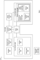
- FIG. 2 is a block diagram of an example digital X-ray imaging system 200 that may be used to implement the handheld X-ray imaging system 100 of FIG. 1 .
- the example digital X-ray imaging system 200 of FIG. 2 includes a frame 202 holding an X-ray generator 204, an X-ray detector 206, a computing device 208, a battery 210, one or more display device(s) 212, one or more operator input device(s) 214, and one or more handle(s) 216.
- the X-ray generator 204 includes an X-ray tube 218, a collimator 220, and a shield switch 222.
- the X-ray tube 218 generates X-rays when energized.
- the X-ray tube 218 operates at voltages between 40kV and 120kV.
- X-ray tube voltages between 70kV and 120kV may be used while staying within acceptable X-ray dosage limits for the operator. Other voltage ranges may also be used.
- the collimator 220 filters the X-ray radiation output by the X-ray tube 218 to more narrowly direct the X-ray radiation at the X-ray detector 206 and any intervening objects.
- the collimator 220 reduces the X-ray dose to the operator of the system 200, reduces undesired X-ray energies to the detector 206 resulting from X-ray scattering, and/or improves the resulting digital image generated at the X-ray detector 206.
- the shield switch 222 selectively enables and/or disables the X-ray tube 218 based on whether a backscatter shielding device 224 is attached to the frame.
- the backscatter shielding device 224 reduces the dose to the operator holding the frame 202 by providing shielding between the collimator 220 and an object under test.
- the example backscatter shielding device 224 includes a switch trigger configured to trigger the shield switch 222 when properly installed.
- the shield switch 222 may be a reed switch or similar magnetically-triggered switch, and the backscatter shielding device 224 includes a magnet.
- the reed switch and magnet are respectively positioned on the frame 202 and the backscatter shielding device 224 such that the magnet triggers the reed switch when the backscatter shielding device 224 is attached to the frame 202.
- the shield switch 222 may include any type of a capacitive sensor, an inductive sensor, a magnetic sensor, an optical sensor, and/or any other type of proximity sensor.
- the shield switch 222 is configured to disable the X-ray tube 218 when the backscatter shielding device 224 is not installed.
- the shield switch 222 may be implemented using, for example, hardware circuitry and/or via software executed by the computing device 208.
- the computing device 208 may selectively override the shield switch 222 to permit operation of the X-ray tube 218 when the backscatter shielding device 224 is not installed.
- the override may be controlled by an administrator or other authorized user.
- the X-ray detector 206 of FIG. 2 generates digital images based on incident X-ray radiation (e.g., generated by the X-ray tube 218 and directed toward the X-ray detector 206 by the collimator 220).
- the example X-ray detector 206 includes a detector housing 226, which holds a scintillation screen 228, a reflector 230, and a digital imaging sensor 232.
- the scintillation screen 228, the reflector 230, and the digital imaging sensor 232 are components of a fluoroscopy detection system 234.
- the example fluoroscopy detection system 234 is configured so that the digital imaging sensor 232 (e.g., a camera, a sensor chip, etc.) receives the image indirectly via the scintillation screen 228 and the reflector 230.
- the fluoroscopy detection system 234 includes a sensor panel (e.g., a CCD panel, a CMOS panel, etc.) configured to receive the X-rays directly, and to generate the digital images.
- a sensor panel e.g., a CCD panel, a CMOS panel, etc.
- An example implementation of the X-ray detector 206 is described below with reference to FIGS. 5-8 .
- the scintillation screen 228, may be replaced with a solid state panel that is coupled to the scintillation screen 228 and has pixels that correspond to portions of the scintillation screen 228.
- Example solid state panels may include CMOS X-ray panels and/or CCD X-ray panels.
- the computing device 208 controls the X-ray tube 218, receives digital images from the X-ray detector 206 (e.g., from the digital imaging sensor 232), and outputs the digital images to the display device 212. Additionally or alternatively, the computing device 208 may store digital images to a storage device. The computing device 208 may output the digital images as digital video to aid in real-time non-destructive testing and/or store digital still images.
- the computing device 208 may provide the digital images to the display device(s) 212 via a wired connection or a wireless connection.
- the computing device 208 includes wireless communication circuitry.
- the display device(s) 212 may be detachable from the frame 202 and held separately from the frame 202 while the computing device 208 wirelessly transmits the digital images to the display device(s) 212.
- the display device(s) 212 may include a smartphone, a tablet computer, a laptop computer, a wireless monitoring device, and/or any other type of display device equipped with wired and/or wireless communications circuitry to communicate with (e.g., receive digital images from) the computing device 208.
- the computing device 208 adds data to the digital images to assist in subsequent analysis of the digital images.
- Example data includes a timestamp, a date stamp, geographic data, or a scanner inclination.
- the example computing device 208 adds the data to the images by adding metadata to the digital image file(s) and/or by superimposing a visual representation of the data onto a portion of the digital images.
- the operator input device(s) 214 enable the operator to configure and/or control the example digital X-ray imaging system 200.
- the operator input device(s) 214 may provide input to the computing device 208, which controls operation and/or configures the settings of the digital X-ray imaging system 200.
- Example operator input device(s) 214 include a trigger (e.g., for controlling activation of the X-ray tube 218), buttons, switches, analog joysticks, thumbpads, trackballs, and/or any other type of user input device.
- the handle(s) 216 are attached to the frame 202 and enable physical control and manipulation of the frame 202, the X-ray generator 204, and the X-ray detector 206.
- one or more of the operator input device(s) 214 are implemented on the handle(s) 216 to enable a user to both physically manipulate and control operation of the digital X-ray imaging system 200.
- FIG. 3 is a perspective view of the first portion 108 of the handheld X-ray imaging system 100 of FIG. 1 , including the X-ray generator 104, the power supply 120, and the operator control handle 112.
- FIG. 3 is illustrated with a portion of a housing 302, while a second portion of the housing (shown in FIG. 1 ) is omitted for visibility of other components.
- the example first portion 108 is further coupled to a computing device 304, such as the computing device 208 of FIG. 2 .
- the computing device 304 is attached to the frame 102 via a printed circuit board 306.
- An X-ray tube 308 (e.g., the X-ray tube 218 of FIG. 2 ) is coupled to a collimator 310 (e.g., the collimator 220 of FIG. 2 ) and controlled by the computing device 304 and/or by an operator input device on the handle 112.
- the handle 112 may include an X-ray trigger 312 (e.g., one of the operator input device(s) 214 of FIG. 2 ).
- the X-ray trigger 312 When actuated (e.g., by the operator of the handheld X-ray imaging system 100), the X-ray trigger 312 activates the X-ray tube 308 to generate X-ray radiation.
- the X-ray trigger 312 may activate the X-ray tube 308 directly and/or via the computing device 304.
- the collimator 310 filters X-ray radiation generated by the X-ray tube 308 to reduce the X-ray radiation that is not directed at the X-ray detector 106 and/or to increase the proportion of X-ray radiation that is directed at the X-ray detector 106 (e.g., radiation that ends up being incident on a scintillator of the X-ray detector 106) relative to radiation not directed at the X-ray detector 106.
- a targeting camera 314 is coupled to the computing device 304 to enable an operator of the handheld X-ray imaging system 100 to determine a target of generated X-rays.
- the example targeting camera 314 generates and outputs digital images (e.g., digital video, digital still images, etc.) to the computing device 304 for display to the operator via the display device 118.
- the digital images of the target e.g., an exterior of the target
- a laser may be projected from the location of the targeting camera 314 toward the X-ray detector 106. The laser illuminates an approximate location on a workpiece that is being scanned by the digital X-ray imaging system 100 and/or output to the display device 118.
- FIG. 4 is a more detailed view of the first portion 108 of the handheld X-ray imaging system of FIG. 3 including the example handle 112.
- the handle 112 is capable of attachment to multiple locations on the frame 102.
- the handle 112 is illustrated at a first location 402 on the frame 102 in FIG. 4 .
- the handle 112 is secured to the housing 302 via multiple screws.
- the handle 112 may be detached from the first location 402 and attached at a second location 404.
- the second location 404 on the housing 302 includes multiple screw nuts 406a-406c and a data connector 408, which match screw nuts and a data connector at the first location 402.
- the example handle 112 may be attached to the second location 404 by connecting a corresponding connector on the handle 112 to the data connector 408 and screwing the handle into the screw nuts 406a-406c.
- FIGS. 5A and 5B illustrate perspective views of the example handle 112 of FIGS. 1 and 3 .
- the handle 112 includes the trigger 312, which enables and/or activates the X-ray tube 308 to output the X-ray radiation.
- the handle 112 includes additional input devices 502, 504 (e.g., operator input devices 214 of FIG. 2 ).
- the input device 502 is a thumbstick, which can be used to input commands to the computing device 304, such as navigating menus, confirming selections, configuring the X-ray tube 308 and/or the X-ray generator 106, changing views and/or any other type of operator input.
- the input device 504 is a push button that may be used by an operator to confirm and/or cancel a selection.
- the computing device 304 controls the X-ray tube 308, the X-ray detector 106 (e.g., the X-ray generator 206 and/or the digital imaging sensor 232 of FIG. 2 ), the display device 118, and/or any other aspect of the digital X-ray imaging system 100 based on input from the trigger 312, the input devices 502, 504, and/or any other input devices.
- the X-ray detector 106 e.g., the X-ray generator 206 and/or the digital imaging sensor 232 of FIG. 2
- the display device 118 e.g., the X-ray generator 206 and/or the digital imaging sensor 232 of FIG. 2
- any other aspect of the digital X-ray imaging system 100 based on input from the trigger 312, the input devices 502, 504, and/or any other input devices.
- the handle 112 includes a data connector 506, which mates to the data connector(s) 408 on the housing 302.
- the data connectors 408, 506 establish a hard-wired connection between the trigger 312 and/or the input devices 502, 504 and the computing device 304 and/or other circuitry.
- the handle 112 includes input guards 508, which protect the input devices 502, 504 from accidental damage.
- the input guards 508 extend from the handle 112 adjacent the input devices 502, 504 and farther than the input devices 502, 504.
- the example handle 112 further includes a trigger lock 510.
- the trigger lock 510 is a mechanical lock that, when activated, mechanically prevents activation of the trigger 312.
- the example trigger lock 510 is a push-button safety that locks the trigger 312 against depression by the operator.
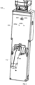
- FIG. 6 is a partially exploded view of the example digital X-ray detector 106 of FIG. 1 .
- FIG. 7 is a perspective view of the example digital X-ray detector 106 of FIG. 1 .
- the X-ray detector 106 includes a detector housing 602, a scintillation screen 604, and a reflector 606.
- the scintillation screen 604 and the reflector 606 are held within the housing 602 and are illustrated in FIG. 6 to show the relationship between the shape of the housing 602 and the geometries of the scintillation screen 604 and the reflector 606.
- the detector housing 602 may be constructed using carbon fiber, aluminum, and/or any other material and/or combination of materials.
- the example detector housing 602 may function as a soft X-ray filter to reduce undesired X-ray radiation at the scintillation screen 604, thereby reducing noise in the resulting digital image.
- the scintillation screen 604 and/or the reflector 606 may be attached to the detector housing 602 using adhesive (e.g., epoxy, glue, etc.) and/or any other attachment technique.
- the detector housing 602 is lined with a layer of lead or another backscatter shielding material to lower the dose to the operator in a handheld system.
- FIG. 8 is a side view of the example digital detector housing, the scintillator, and the reflector.
- FIG. 9 is a side view of the example digital X-ray detector 106 of FIG. 1 , illustrating imaging of incident X-rays by the digital X-ray detector. As illustrated in FIG. 9 , a digital imaging sensor 612 is oriented to capture light generated by the scintillation screen 604 in response to incident X-ray radiation.
- the scintillation screen 604 converts incident X-rays 608 to visible light 610.
- An example scintillation screen 604 that may be used in a handheld X-ray scanner has a surface area of 4 inches by 6 inches.
- the size and material of the scintillation screen 604 at least partially determines the size, brightness, and/or resolution of the resulting digital images.
- the example scintillation screen is Gadox (Gadolinium oxysulphide) doped with Terbium, which emits a peak visible light at a wavelength of substantially 560nm.
- the example reflector 606 is a mirror that reflects visible light generated by the scintillation screen 604 to the digital imaging sensor 612 (e.g., via a lens 614).
- the example reflector 606 has the same surface area (e.g., 4 inches by 6 inches) as the scintillation screen 604, and is oriented at an angle 616 to direct the visible light 610 to the digital imaging sensor 612 and/or the lens 614.
- An example angle 616 is 30 degrees, which enables a 4 inch by 6 inch scintillation screen and a 4 inch by 6 inch reflector 606 to fit within a housing having a thickness 618 of less than 2.5 inches. In other examples, the angle 616 is an angle less than 45 degrees.
- the digital X-ray detector 106 may include optics such as prisms to direct the visible light 610 to the digital imaging sensor 612.
- the example digital imaging sensor 612 is a solid state sensor such as a CMOS camera.
- the digital imaging sensor 612 has a field of view of 143 degrees to capture light from substantially the entirety of the reflector 606.
- the digital imaging sensor 612 is coupled to an imager bracket 620 via a mounting brackets 622.
- the detector housing 602 is also coupled to the imager bracket 620.
- the imager bracket 620 couples both the detector housing 602 and the digital imaging sensor 612 to the frame 102 of the handheld X-ray imaging system 100.
- the mounting brackets 622 includes slots 624 to which an imaging bracket 626 is adjustably coupled.
- the digital imaging sensor 612 is attached to the imaging bracket 626 (e.g., via a printed circuit board).
- the imaging bracket 626 may be adjusted and secured along the length of the slots 624 to adjust an angle of the digital imaging sensor 612 relative to the reflector 606.
- the field of view of the digital imaging sensor 612 is oriented substantially perpendicularly to the scintillation screen, within the angular limits permitted using the slots 624 and the imaging bracket 626.
- the example imager bracket 620 may include a data connector 628 ( FIG. 8 ) to enable sufficient data throughput from the digital imaging sensor 612 to a computing device or other image display and/or image storage devices.
- An example data connector 628 may be a USB 3.0 connector to connect a USB 3.0 bus between the digital imaging sensor 612 and the receiving device.
- the USB 3.0 bus provides sufficient bandwidth between the digital imaging device 608 and the receiving device for high-definition video or better resolution.
- CMOS panel produces digital images based on visible light generated by the scintillator, and outputs the digital images to the computing device 304.
- FIG. 10 is a side view of the handheld X-ray imaging system of FIG. 1 , illustrating scanning of an object 1002 under test by directing X-rays 1004 from the X-ray tube 308 to the X-ray detector 106.
- the collimator 310 reduces X-ray radiation that is not directed at the X-ray detector 106, so the concentration of the X-ray radiation 1004 that is not scattered by the object 1002 is incident on the X-ray detector 106.
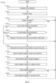
- FIG. 11 is a flowchart representative of example machine readable instructions 1100 which may be executed by the example computing device 208 of FIG. 2 to perform digital X-ray imaging.
- the example machine readable instructions 1100 of FIG. 11 are described below with reference to the digital X-ray imaging system 200 of FIG. 2 , but may be performed by the digital X-ray imaging system 100 of FIG. 1 .
- the example computing device 208 initializes the X-ray detector 206. For example, the computing device 208 may verify that the X-ray detector 206 is in communication with the computing device 208 and/or is configured to capture digital images of X-ray radiation.
- an operator of the digital X-ray imaging system 200 may position the frame 202 adjacent on object under test, such that the object under test is located between the X-ray detector 206 and the X-ray tube 218.
- the computing device 208 determines whether a trigger is activated. For example, the computing device 208 may activate the X-ray tube 218 in response to activation of a trigger (e.g., a physical trigger, a button, a switch, etc.) by an operator. If the trigger has not been activated (block 1104), control returns to block 1104 to await activation of the trigger.
- a trigger e.g., a physical trigger, a button, a switch, etc.
- the computing device 208 determines whether the X-ray tube voltage is at least a threshold voltage.
- the X-ray tube voltage may be configured to be between 70kV and 120kV, in which case the computing device 208 requires the backscatter shielding device 224 to be detected (e.g., via the shield switch 222).
- the computing device 208 determines whether a backscatter shield is detected. For example, the computing device 208 may determine whether the backscatter shield (e.g., the backscatter shielding device 224, the backscatter shield 300, the backscatter shield 600) is installed using the shield switch 222. If the backscatter shield is not detected (block 1106), at block 1108 the computing device 208 disables the X-ray tube 218 and outputs a backscatter shield alert (e.g., via a visual and/or audible alarm, via the display device 212, etc.). Control then returns to block 1104.
- the backscatter shield e.g., the backscatter shielding device 224, the backscatter shield 300, the backscatter shield 600
- the X-ray tube 218 If the backscatter shield is detected (block 1106), or if the X-ray tube voltage is less than the threshold (block 1105), at block 1110 the X-ray tube 218 generates and outputs X-ray radiation.
- the X-ray detector 106 e.g., via the scintillation screen 228, the reflector 230, and the digital imaging sensor 232, and/or via a solid state panel coupled to a scintillator
- captures digital image(s) e.g., digital still images and/or digital video.
- the X-ray detector 106 provides the captured digital image(s) to the computing device 208.
- the computing device 208 adds the auxiliary data to the digital image(s).
- Example auxiliary data includes a timestamp, a date stamp, geographic data, and/or an inclination of the frame 202, the X-ray detector 206, the X-ray tube 218, and/or any other component of the digital X-ray imaging system 200.
- the computing device 208 outputs the digital image(s) to the display device(s) 218 (e.g., via a wired and/or wireless connection).
- the computing device 208 outputs the digital image(s) to an external computing device such as a laptop, a smartphone, a server, a tablet computer, a personal computer, and/or any other type of external computing device.
- the computing device 208 determines whether the digital image(s) are to be stored (e.g., in a storage device). If the digital image(s) are to be stored (block 1118), at block 1120 the example computing device 208 stores the image(s).
- the example computing device 208 may be configured to store the digital image(s) in one or more available storage devices, such as a removable storage device.
- blocks 1110-1120 may be iterated substantially continuously until the trigger is deactivated.
- FIG. 12 is a block diagram of an example computing system 1200 that may be used to implement the computing device 208 of FIG. 2 .
- the example computing system 1200 may be implemented using a personal computer, a server, a smartphone, a laptop computer, a workstation, a tablet computer, and/or any other type of computing device.
- the example computing system 1200 of FIG. 12 includes a processor 1202.
- the example processor 1202 may be any general purpose central processing unit (CPU) from any manufacturer.
- the processor 1202 may include one or more specialized processing units, such as RISC processors with an ARM core, graphic processing units, digital signal processors, and/or system-on-chips (SoC).
- the processor 1202 executes machine readable instructions 1204 that may be stored locally at the processor (e.g., in an included cache or SoC), in a random access memory 1206 (or other volatile memory), in a read only memory 1208 (or other non-volatile memory such as FLASH memory), and/or in a mass storage device 1210.
- the example mass storage device 1210 may be a hard drive, a solid state storage drive, a hybrid drive, a RAID array, and/or any other mass data storage device.
- a bus 1212 enables communications between the processor 1202, the RAM 1206, the ROM 1208, the mass storage device 1210, a network interface 1214, and/or an input/output interface 1216.
- the example network interface 1214 includes hardware, firmware, and/or software to connect the computing system 1200 to a communications network 1218 such as the Internet.
- the network interface 1214 may include IEEE 1202.X-compliant wireless and/or wired communications hardware for transmitting and/or receiving communications.
- the example I/O interface 1216 of FIG. 12 includes hardware, firmware, and/or software to connect one or more input/output devices 1220 to the processor 1202 for providing input to the processor 1202 and/or providing output from the processor 1202.
- the I/O interface 1216 may include a graphics processing unit for interfacing with a display device, a universal serial bus port for interfacing with one or more USB-compliant devices, a FireWire, a field bus, and/or any other type of interface.
- Example I/O device(s) 1220 may include a keyboard, a keypad, a mouse, a trackball, a pointing device, a microphone, an audio speaker, an optical media drive, a multi-touch touch screen, a gesture recognition interface, a display device (e.g., the display device(s) 118, 212) a magnetic media drive, and/or any other type of input and/or output device.
- a keyboard e.g., a keypad, a mouse, a trackball, a pointing device, a microphone, an audio speaker, an optical media drive, a multi-touch touch screen, a gesture recognition interface, a display device (e.g., the display device(s) 118, 212) a magnetic media drive, and/or any other type of input and/or output device.
- the example computing system 1200 may access a non-transitory machine readable medium 1222 via the I/O interface 1216 and/or the I/O device(s) 1220.
- machine readable medium 1222 of FIG. 12 include optical discs (e.g., compact discs (CDs), digital versatile/video discs (DVDs), Blu-ray discs, etc.), magnetic media (e.g., floppy disks), portable storage media (e.g., portable flash drives, secure digital (SD) cards, etc.), and/or any other type of removable and/or installed machine readable media.
- optical discs e.g., compact discs (CDs), digital versatile/video discs (DVDs), Blu-ray discs, etc.
- magnetic media e.g., floppy disks
- portable storage media e.g., portable flash drives, secure digital (SD) cards, etc.
- SD secure digital
- Example wireless interfaces, protocols, and/or standards that may be supported and/or used by the network interface(s) 1214 and/or the I/O interface(s) 1216, such as to communicate with the display device(s) 212 include wireless personal area network (WPAN) protocols, such as Bluetooth (IEEE 802.15); near field communication (NFC) standards; wireless local area network (WLAN) protocols, such as WiFi (IEEE 802.11); cellular standards, such as 2G/2G+ (e.g., GSM/GPRS/EDGE, and IS-95 or cdmaOne) and/or 2G/2G+ (e.g., CDMA2000, UMTS, and HSPA); 4G standards, such as WiMAX (IEEE 802.16) and LTE; Ultra-Wideband (UWB); etc.
- WPAN wireless personal area network
- NFC near field communication
- WLAN wireless local area network
- WiFi IEEE 802.11
- cellular standards such as 2G/2G+ (e.g., GSM/GPRS
- Example wired interfaces, protocols, and/or standards that may be supported and/or used by the network interface(s) 1214 and/or the I/O interface(s) 1216, such as to communicate with the display device(s) 212 include comprise Ethernet (IEEE 802.3), Fiber Distributed Data Interface (FDDI), Integrated Services Digital Network (ISDN), cable television and/or internet (ATSC, DVB-C, DOCSIS), Universal Serial Bus (USB) based interfaces, etc.
- the processor 202, the network interface(s) 1214, and/or the I/O interface(s) 1216, and/or the display device 212 may perform signal processing operations such as, for example, filtering, amplification, analog-to-digital conversion and/or digital-to-analog conversion, up-conversion/down-conversion of baseband signals, encoding/decoding, encryption/decryption, modulation/demodulation, and/or any other appropriate signal processing.
- signal processing operations such as, for example, filtering, amplification, analog-to-digital conversion and/or digital-to-analog conversion, up-conversion/down-conversion of baseband signals, encoding/decoding, encryption/decryption, modulation/demodulation, and/or any other appropriate signal processing.
- the computing device 208 and/or the display device 212 may use one or more antennas for wireless communications and/or one or more wired port(s) for wired communications.
- the antenna(s) may be any type of antenna (e.g., directional antennas, omnidirectional antennas, multi-input multi-output (MIMO) antennas, etc.) suited for the frequencies, power levels, diversity, and/or other parameters required for the wireless interfaces and/or protocols used to communicate.
- the port(s) may include any type of connectors suited for the communications over wired interfaces/protocols supported by the computing device 208 and/or the display device 212.
- the port(s) may include an Ethernet over twisted pair port, a USB port, an HDMI port, a passive optical network (PON) port, and/or any other suitable port for interfacing with a wired or optical cable.
- PON passive optical network
- the present methods and systems may be realized in hardware, software, and/or a combination of hardware and software.
- the present methods and/or systems may be realized in a centralized fashion in at least one computing system, or in a distributed fashion where different elements are spread across several interconnected computing systems. Any kind of computing system or other apparatus adapted for carrying out the methods described herein is suited.
- a typical combination of hardware and software may include a general-purpose computing system with a program or other code that, when being loaded and executed, controls the computing system such that it carries out the methods described herein.
- Another typical implementation may comprise an application specific integrated circuit or chip.
- Some implementations may comprise a non-transitory machine-readable (e.g., computer readable) medium (e.g., FLASH drive, optical disk, magnetic storage disk, or the like) having stored thereon one or more lines of code executable by a machine, thereby causing the machine to perform processes as described herein.
- a non-transitory machine-readable medium e.g., FLASH drive, optical disk, magnetic storage disk, or the like
- non-transitory machine-readable medium is defined to include all types of machine readable storage media and to exclude propagating signals.
- circuits and circuitry refer to physical electronic components (i.e. hardware) and any software and/or firmware ("code") which may configure the hardware, be executed by the hardware, and or otherwise be associated with the hardware.
- code software and/or firmware
- a particular processor and memory may comprise a first "circuit” when executing a first one or more lines of code and may comprise a second "circuit” when executing a second one or more lines of code.
- and/or means any one or more of the items in the list joined by “and/or”.
- x and/or y means any element of the three-element set ⁇ (x), (y), (x, y) ⁇ .
- x and/or y means “one or both of x and y”.
- x, y, and/or z means any element of the seven-element set ⁇ (x), (y), (z), (x, y), (x, z), (y, z), (x, y, z) ⁇ .
- x, y and/or z means “one or more of x, y and z”.
- exemplary means serving as a non-limiting example, instance, or illustration.
- the terms "e.g.,” and “for example” set off lists of one or more non-limiting examples, instances, or illustrations.
- circuitry is "operable" to perform a function whenever the circuitry comprises the necessary hardware and code (if any is necessary) to perform the function, regardless of whether performance of the function is disabled or not enabled (e.g., by a user-configurable setting, factory trim, etc.).
Landscapes
- Life Sciences & Earth Sciences (AREA)
- Health & Medical Sciences (AREA)
- Engineering & Computer Science (AREA)
- Medical Informatics (AREA)
- Physics & Mathematics (AREA)
- High Energy & Nuclear Physics (AREA)
- Molecular Biology (AREA)
- Biomedical Technology (AREA)
- Animal Behavior & Ethology (AREA)
- Veterinary Medicine (AREA)
- Nuclear Medicine, Radiotherapy & Molecular Imaging (AREA)
- Optics & Photonics (AREA)
- Pathology (AREA)
- Radiology & Medical Imaging (AREA)
- Public Health (AREA)
- Heart & Thoracic Surgery (AREA)
- General Health & Medical Sciences (AREA)
- Surgery (AREA)
- Biophysics (AREA)
- General Physics & Mathematics (AREA)
- Spectroscopy & Molecular Physics (AREA)
- Metallurgy (AREA)
- Ceramic Engineering (AREA)
- General Engineering & Computer Science (AREA)
- Multimedia (AREA)
- Signal Processing (AREA)
- Human Computer Interaction (AREA)
- Computer Networks & Wireless Communication (AREA)
- Apparatus For Radiation Diagnosis (AREA)
- Measurement Of Radiation (AREA)
- Analysing Materials By The Use Of Radiation (AREA)
Description
- This patent claims priority to
U.S. Patent Application Serial No. 16/269,459, filed February 6, 2019 U.S. Provisional Patent Application Serial No. 62/627,473, filed February 7, 2018 U.S. Provisional Patent Application Serial No. 62/627,469, filed February 7, 2018 U.S. Provisional Patent Application Serial No. 62/627,464, filed February 7, 2018 U.S. Provisional Patent Application Serial No. 62/627,466, filed February 7, 2018 - This disclosure relates generally to radiography and, more particularly, to systems and methods for digital X-ray imaging.
WO2016172611A1 discloses a portable X-ray device with a C-shaped support arm with an X-ray source on one end and an X-ray detector on the other end.WO2014022217A1 discloses a hand-held imaging device with a radiation source and detector fixed by a frame.WO2005081956A2 discloses an X-ray device with a housing containing an X-ray tube, power system and an X-ray sensor.US2012148031A1 discloses a fluoroscopic imaging system with a support carrying an X-ray source and an X-ray detector. - Systems for digital X-ray imaging are disclosed, substantially as illustrated by and described in connection with at least one of the figures, as set forth more completely in the claims.
- These and other features, aspects, and advantages of the present disclosure will become better understood when the following detailed description is read with reference to the accompanying drawings in which like characters represent like parts throughout the drawings, wherein:
-
FIG. 1 is a perspective view of an example handheld X-ray imaging system to generate and output digital images and/or video based on incident X-rays, in accordance with aspects of this disclosure. -
FIG. 2 is a block diagram of the example handheld X-ray imaging system ofFIG. 1 . -
FIG. 3 is a perspective view of a first portion of the handheld X-ray imaging system ofFIG. 1 , including an X-ray generator, a power supply, an operator control handle. -
FIG. 4 is a more detailed view of the first portion of the handheld X-ray imaging system ofFIG. 3 including the example handle. -
FIGS. 5A and 5B illustrate perspective views of the example handle ofFIG. 3 . -
FIG. 6 is a partially exploded view of the example digital X-ray detector ofFIG. 1 . -
FIG. 7 is a perspective view of a first portion of the handheld X-ray imaging system ofFIG. 1 , including a digital X-ray detector assembly. -
FIG. 8 is a side view of the example digital detector housing, the scintillator, and the reflector. -
FIG. 9 is a side view of the example digital X-ray detector ofFIG. 1 , illustrating imaging of incident X-rays by the digital X-ray detector. -
FIG. 10 is a side view of the handheld X-ray imaging system ofFIG. 1 , illustrating scanning of an object under test by directing X-rays from the X-ray tube to the X-ray detector. -
FIG. 11 is a flowchart representative of example machine readable instructions which may be executed by the example computing device ofFIG. 2 to perform digital X-ray imaging, in accordance with aspects of this disclosure. -
FIG. 12 is a block diagram of an example computing system that may be used to implement the computing device ofFIG. 2 . - The figures are not necessarily to scale. Wherever appropriate, similar or identical reference numerals are used to refer to similar or identical components.
- Disclosed example handheld X-ray imaging systems enable real-time generation and/or display of digital images during X-ray radiography. In contrast with conventional systems, disclosed examples provide an all-in-one X-ray radiography unit that does not require extraneous equipment for power, X-ray generation, radiograph capture, radiograph display, or radiograph storage.
- Disclosed example handheld X-ray imaging systems reduce operator fatigue relative to conventional scanning devices by having a reduced weight, e.g. less than 20 pounds (9 kg), and/or by providing improved weight distribution that concentrates the weight of the handheld X-ray imaging system near the operator's body.
- As used herein, the term "real-time" refers to the actual time elapsed in the performance of a computation by a computing device, the result of the computation being required for the continuation of a physical process (i.e., no significant delays are introduced). For example, real-time display of captured images includes processing captured image data and displaying the resulting output images to create the perception to a user that the images are displayed immediately upon capture. As used herein, the term "portable" includes handheld (e.g., capable of being carried and operated by a single person) and/or wheeled (e.g., capable of being transported and operated while wheels are attached and/or placed on wheels).
-
FIG. 1 is a perspective view of an example handheldX-ray imaging system 100 to generate and output digital images and/or video based on incident X-rays. The example handheldX-ray imaging system 100 may be used to perform non-destructive testing (NDT), medical scanning, security scanning, and/or any other scanning application. - The
system 100 ofFIG. 1 includes aframe 102 that holds anX-ray generator 104 and anX-ray detector 106. In the example ofFIG. 1 , theframe 102 is C-shaped, such that theX-ray generator 104 directs X-ray radiation toward theX-ray detector 106. As described in more detail below, theframe 102 is positionable (e.g., held by an operator, supported by an external support structure and/or manipulated by the operator, etc.) around an object to be scanned with X-rays. Theexample frame 102 is constructed using carbon fiber and/or machined aluminum. - The
X-ray generator 104 is located on afirst section 108 of the C-shapedframe 102 generates and outputs X-ray radiation, which traverses and/or scatters based on the state of the object under test. TheX-ray detector 106 is located on asecond section 110 of the frame 102 (e.g., opposite the first section 108) and receives incident radiation generated by theX-ray generator 104. - The
example frame 102 may be manipulated using one ormore handles handles 114 is adjustable and may be secured to provide the operator with leverage to manipulate theframe 102. The example handle 114 may be oriented with multiple degrees of freedom and/or adjusted along a length of acentral section 116 of theframe 102. A second one of thehandles 112 is an operator control handle, and enables an operator to both mechanically manipulate theframe 102 and control the operation of the handheldX-ray imaging system 100. - During operation, the handheld
X-ray imaging system 100 generates digital images (e.g., digital video and/or digital still images) from the X-ray radiation. The handheldX-ray imaging system 100 may store the digital images on one or more storage devices, display the digital images on adisplay device 118, and/or transmit the digital images to a remote receiver. Theexample display device 118 is attachable to theexample frame 102 and/or may be oriented for viewing by the operator. Thedisplay device 118 may also be detached from theframe 102. When detached, thedisplay device 118 receives the digital images (e.g., still images and/or video) via a wireless data connection. When attached, thedisplay device 118 may receive the digital images via a wired connection and/or a wireless connection. - A
power supply 120, such as a detachable battery, is attached to theframe 102 and provides power to theX-ray generator 104, theX-ray detector 106, and/or other circuitry of the handheldX-ray imaging system 100. Anexample power supply 120 that may be used is a lithium-ion battery pack. Thedisplay device 118 may receive power from thepower supply 120 and/or from another power source such as an internal battery of thedisplay device 118. - The example
central section 116 of theframe 102 is coupled to thefirst section 108 via a joint 122 and to thesecond section 110 via a joint 124. The example joints 122, 124 are hollow to facilitate routing of cabling between thesections joints first section 108 and thesecond section 110 to be folded toward the center section to further improve the compactness of the handheldX-ray imaging system 100 when not in use (e.g., during storage and/or travel). -
FIG. 2 is a block diagram of an example digitalX-ray imaging system 200 that may be used to implement the handheldX-ray imaging system 100 ofFIG. 1 . The example digitalX-ray imaging system 200 ofFIG. 2 includes aframe 202 holding anX-ray generator 204, anX-ray detector 206, acomputing device 208, abattery 210, one or more display device(s) 212, one or more operator input device(s) 214, and one or more handle(s) 216. - The
X-ray generator 204 includes anX-ray tube 218, acollimator 220, and ashield switch 222. TheX-ray tube 218 generates X-rays when energized. In some examples, theX-ray tube 218 operates at voltages between 40kV and 120kV. In combination with a shielding device, X-ray tube voltages between 70kV and 120kV may be used while staying within acceptable X-ray dosage limits for the operator. Other voltage ranges may also be used. - The
collimator 220 filters the X-ray radiation output by theX-ray tube 218 to more narrowly direct the X-ray radiation at theX-ray detector 206 and any intervening objects. Thecollimator 220 reduces the X-ray dose to the operator of thesystem 200, reduces undesired X-ray energies to thedetector 206 resulting from X-ray scattering, and/or improves the resulting digital image generated at theX-ray detector 206. - The
shield switch 222 selectively enables and/or disables theX-ray tube 218 based on whether abackscatter shielding device 224 is attached to the frame. Thebackscatter shielding device 224 reduces the dose to the operator holding theframe 202 by providing shielding between thecollimator 220 and an object under test. The examplebackscatter shielding device 224 includes a switch trigger configured to trigger theshield switch 222 when properly installed. For example, theshield switch 222 may be a reed switch or similar magnetically-triggered switch, and thebackscatter shielding device 224 includes a magnet. The reed switch and magnet are respectively positioned on theframe 202 and thebackscatter shielding device 224 such that the magnet triggers the reed switch when thebackscatter shielding device 224 is attached to theframe 202. Theshield switch 222 may include any type of a capacitive sensor, an inductive sensor, a magnetic sensor, an optical sensor, and/or any other type of proximity sensor. - The
shield switch 222 is configured to disable theX-ray tube 218 when thebackscatter shielding device 224 is not installed. Theshield switch 222 may be implemented using, for example, hardware circuitry and/or via software executed by thecomputing device 208. In some examples, thecomputing device 208 may selectively override theshield switch 222 to permit operation of theX-ray tube 218 when thebackscatter shielding device 224 is not installed. The override may be controlled by an administrator or other authorized user. - The
X-ray detector 206 ofFIG. 2 generates digital images based on incident X-ray radiation (e.g., generated by theX-ray tube 218 and directed toward theX-ray detector 206 by the collimator 220). Theexample X-ray detector 206 includes a detector housing 226, which holds ascintillation screen 228, areflector 230, and adigital imaging sensor 232. Thescintillation screen 228, thereflector 230, and thedigital imaging sensor 232 are components of afluoroscopy detection system 234. The examplefluoroscopy detection system 234 is configured so that the digital imaging sensor 232 (e.g., a camera, a sensor chip, etc.) receives the image indirectly via thescintillation screen 228 and thereflector 230. In other examples, thefluoroscopy detection system 234 includes a sensor panel (e.g., a CCD panel, a CMOS panel, etc.) configured to receive the X-rays directly, and to generate the digital images. An example implementation of theX-ray detector 206 is described below with reference toFIGS. 5-8 . - In some other examples, the
scintillation screen 228, may be replaced with a solid state panel that is coupled to thescintillation screen 228 and has pixels that correspond to portions of thescintillation screen 228. Example solid state panels may include CMOS X-ray panels and/or CCD X-ray panels. - The
computing device 208 controls theX-ray tube 218, receives digital images from the X-ray detector 206 (e.g., from the digital imaging sensor 232), and outputs the digital images to thedisplay device 212. Additionally or alternatively, thecomputing device 208 may store digital images to a storage device. Thecomputing device 208 may output the digital images as digital video to aid in real-time non-destructive testing and/or store digital still images. - As mentioned above, the
computing device 208 may provide the digital images to the display device(s) 212 via a wired connection or a wireless connection. To this end, thecomputing device 208 includes wireless communication circuitry. For example, the display device(s) 212 may be detachable from theframe 202 and held separately from theframe 202 while thecomputing device 208 wirelessly transmits the digital images to the display device(s) 212. The display device(s) 212 may include a smartphone, a tablet computer, a laptop computer, a wireless monitoring device, and/or any other type of display device equipped with wired and/or wireless communications circuitry to communicate with (e.g., receive digital images from) thecomputing device 208. - In some examples, the
computing device 208 adds data to the digital images to assist in subsequent analysis of the digital images. Example data includes a timestamp, a date stamp, geographic data, or a scanner inclination. Theexample computing device 208 adds the data to the images by adding metadata to the digital image file(s) and/or by superimposing a visual representation of the data onto a portion of the digital images. - The operator input device(s) 214 enable the operator to configure and/or control the example digital
X-ray imaging system 200. For example, the operator input device(s) 214 may provide input to thecomputing device 208, which controls operation and/or configures the settings of the digitalX-ray imaging system 200. Example operator input device(s) 214 include a trigger (e.g., for controlling activation of the X-ray tube 218), buttons, switches, analog joysticks, thumbpads, trackballs, and/or any other type of user input device. - The handle(s) 216 are attached to the
frame 202 and enable physical control and manipulation of theframe 202, theX-ray generator 204, and theX-ray detector 206. In some examples, one or more of the operator input device(s) 214 are implemented on the handle(s) 216 to enable a user to both physically manipulate and control operation of the digitalX-ray imaging system 200. -
FIG. 3 is a perspective view of thefirst portion 108 of the handheldX-ray imaging system 100 ofFIG. 1 , including theX-ray generator 104, thepower supply 120, and the operator control handle 112.FIG. 3 is illustrated with a portion of ahousing 302, while a second portion of the housing (shown inFIG. 1 ) is omitted for visibility of other components. - The example
first portion 108 is further coupled to acomputing device 304, such as thecomputing device 208 ofFIG. 2 . Thecomputing device 304 is attached to theframe 102 via a printedcircuit board 306. - An X-ray tube 308 (e.g., the
X-ray tube 218 ofFIG. 2 ) is coupled to a collimator 310 (e.g., thecollimator 220 ofFIG. 2 ) and controlled by thecomputing device 304 and/or by an operator input device on thehandle 112. As shown inFIG. 3 , thehandle 112 may include an X-ray trigger 312 (e.g., one of the operator input device(s) 214 ofFIG. 2 ). When actuated (e.g., by the operator of the handheld X-ray imaging system 100), theX-ray trigger 312 activates theX-ray tube 308 to generate X-ray radiation. TheX-ray trigger 312 may activate theX-ray tube 308 directly and/or via thecomputing device 304. - The
collimator 310 filters X-ray radiation generated by theX-ray tube 308 to reduce the X-ray radiation that is not directed at theX-ray detector 106 and/or to increase the proportion of X-ray radiation that is directed at the X-ray detector 106 (e.g., radiation that ends up being incident on a scintillator of the X-ray detector 106) relative to radiation not directed at theX-ray detector 106. - A targeting
camera 314 is coupled to thecomputing device 304 to enable an operator of the handheldX-ray imaging system 100 to determine a target of generated X-rays. Theexample targeting camera 314 generates and outputs digital images (e.g., digital video, digital still images, etc.) to thecomputing device 304 for display to the operator via thedisplay device 118. The digital images of the target (e.g., an exterior of the target) may be saved in association with the digital images of the X-ray scanning to provide contextual information about the location or object from which digital X-ray images are captured. Additionally or alternatively, a laser may be projected from the location of the targetingcamera 314 toward theX-ray detector 106. The laser illuminates an approximate location on a workpiece that is being scanned by the digitalX-ray imaging system 100 and/or output to thedisplay device 118. -
FIG. 4 is a more detailed view of thefirst portion 108 of the handheld X-ray imaging system ofFIG. 3 including theexample handle 112. To improve the handling of the digitalX-ray imaging system 100, thehandle 112 is capable of attachment to multiple locations on theframe 102. Thehandle 112 is illustrated at a first location 402 on theframe 102 inFIG. 4 . In the example ofFIG. 4 , thehandle 112 is secured to thehousing 302 via multiple screws. - The
handle 112 may be detached from the first location 402 and attached at a second location 404. As illustrated inFIG. 4 , the second location 404 on thehousing 302 includesmultiple screw nuts 406a-406c and adata connector 408, which match screw nuts and a data connector at the first location 402. The example handle 112 may be attached to the second location 404 by connecting a corresponding connector on thehandle 112 to thedata connector 408 and screwing the handle into thescrew nuts 406a-406c. -
FIGS. 5A and 5B illustrate perspective views of the example handle 112 ofFIGS. 1 and3 . As mentioned above, thehandle 112 includes thetrigger 312, which enables and/or activates theX-ray tube 308 to output the X-ray radiation. Thehandle 112 includesadditional input devices 502, 504 (e.g.,operator input devices 214 ofFIG. 2 ). Theinput device 502 is a thumbstick, which can be used to input commands to thecomputing device 304, such as navigating menus, confirming selections, configuring theX-ray tube 308 and/or theX-ray generator 106, changing views and/or any other type of operator input. Theinput device 504 is a push button that may be used by an operator to confirm and/or cancel a selection. Thecomputing device 304 controls theX-ray tube 308, the X-ray detector 106 (e.g., theX-ray generator 206 and/or thedigital imaging sensor 232 ofFIG. 2 ), thedisplay device 118, and/or any other aspect of the digitalX-ray imaging system 100 based on input from thetrigger 312, theinput devices - The
handle 112 includes adata connector 506, which mates to the data connector(s) 408 on thehousing 302. Thedata connectors trigger 312 and/or theinput devices computing device 304 and/or other circuitry. - The
handle 112 includes input guards 508, which protect theinput devices handle 112 adjacent theinput devices input devices - The example handle 112 further includes a
trigger lock 510. Thetrigger lock 510 is a mechanical lock that, when activated, mechanically prevents activation of thetrigger 312. Theexample trigger lock 510 is a push-button safety that locks thetrigger 312 against depression by the operator. -
FIG. 6 is a partially exploded view of the exampledigital X-ray detector 106 ofFIG. 1 .FIG. 7 is a perspective view of the exampledigital X-ray detector 106 ofFIG. 1 . As illustrated inFIG. 6 , theX-ray detector 106 includes adetector housing 602, ascintillation screen 604, and areflector 606. Thescintillation screen 604 and thereflector 606 are held within thehousing 602 and are illustrated inFIG. 6 to show the relationship between the shape of thehousing 602 and the geometries of thescintillation screen 604 and thereflector 606. - The
detector housing 602 may be constructed using carbon fiber, aluminum, and/or any other material and/or combination of materials. Theexample detector housing 602 may function as a soft X-ray filter to reduce undesired X-ray radiation at thescintillation screen 604, thereby reducing noise in the resulting digital image. Thescintillation screen 604 and/or thereflector 606 may be attached to thedetector housing 602 using adhesive (e.g., epoxy, glue, etc.) and/or any other attachment technique. In some examples, thedetector housing 602 is lined with a layer of lead or another backscatter shielding material to lower the dose to the operator in a handheld system. -
FIG. 8 is a side view of the example digital detector housing, the scintillator, and the reflector.FIG. 9 is a side view of the exampledigital X-ray detector 106 ofFIG. 1 , illustrating imaging of incident X-rays by the digital X-ray detector. As illustrated inFIG. 9 , adigital imaging sensor 612 is oriented to capture light generated by thescintillation screen 604 in response to incident X-ray radiation. - The
scintillation screen 604 convertsincident X-rays 608 tovisible light 610. Anexample scintillation screen 604 that may be used in a handheld X-ray scanner has a surface area of 4 inches by 6 inches. The size and material of thescintillation screen 604 at least partially determines the size, brightness, and/or resolution of the resulting digital images. The example scintillation screen is Gadox (Gadolinium oxysulphide) doped with Terbium, which emits a peak visible light at a wavelength of substantially 560nm. - The
example reflector 606 is a mirror that reflects visible light generated by thescintillation screen 604 to the digital imaging sensor 612 (e.g., via a lens 614). Theexample reflector 606 has the same surface area (e.g., 4 inches by 6 inches) as thescintillation screen 604, and is oriented at anangle 616 to direct thevisible light 610 to thedigital imaging sensor 612 and/or thelens 614. Anexample angle 616 is 30 degrees, which enables a 4 inch by 6 inch scintillation screen and a 4 inch by 6inch reflector 606 to fit within a housing having athickness 618 of less than 2.5 inches. In other examples, theangle 616 is an angle less than 45 degrees. Other sizes and/or geometries may be used for thescintillation screen 604 and/or thereflector 606. Additionally or alternatively, thedigital X-ray detector 106 may include optics such as prisms to direct thevisible light 610 to thedigital imaging sensor 612. - The example
digital imaging sensor 612 is a solid state sensor such as a CMOS camera. In the illustrated example using thescintillation screen 604 and thereflector 606, and a6mm lens 614, thedigital imaging sensor 612 has a field of view of 143 degrees to capture light from substantially the entirety of thereflector 606. - The
digital imaging sensor 612 is coupled to animager bracket 620 via a mountingbrackets 622. Thedetector housing 602 is also coupled to theimager bracket 620. Theimager bracket 620 couples both thedetector housing 602 and thedigital imaging sensor 612 to theframe 102 of the handheldX-ray imaging system 100. - The mounting
brackets 622 includesslots 624 to which animaging bracket 626 is adjustably coupled. Thedigital imaging sensor 612 is attached to the imaging bracket 626 (e.g., via a printed circuit board). Theimaging bracket 626 may be adjusted and secured along the length of theslots 624 to adjust an angle of thedigital imaging sensor 612 relative to thereflector 606. The field of view of thedigital imaging sensor 612 is oriented substantially perpendicularly to the scintillation screen, within the angular limits permitted using theslots 624 and theimaging bracket 626. - The
example imager bracket 620 may include a data connector 628 (FIG. 8 ) to enable sufficient data throughput from thedigital imaging sensor 612 to a computing device or other image display and/or image storage devices. Anexample data connector 628 may be a USB 3.0 connector to connect a USB 3.0 bus between thedigital imaging sensor 612 and the receiving device. The USB 3.0 bus provides sufficient bandwidth between thedigital imaging device 608 and the receiving device for high-definition video or better resolution. - While an example implementation of the
X-ray detector 106 is described above, other example implementations of theX-ray detector 106 include using a solid state image sensor, such as a CMOS panel or a CCD panel, coupled directly to a scintillator. The CMOS panel produces digital images based on visible light generated by the scintillator, and outputs the digital images to thecomputing device 304. -
FIG. 10 is a side view of the handheld X-ray imaging system ofFIG. 1 , illustrating scanning of anobject 1002 under test by directingX-rays 1004 from theX-ray tube 308 to theX-ray detector 106. As mentioned above, thecollimator 310 reduces X-ray radiation that is not directed at theX-ray detector 106, so the concentration of theX-ray radiation 1004 that is not scattered by theobject 1002 is incident on theX-ray detector 106. -
FIG. 11 is a flowchart representative of example machinereadable instructions 1100 which may be executed by theexample computing device 208 ofFIG. 2 to perform digital X-ray imaging. The example machinereadable instructions 1100 ofFIG. 11 are described below with reference to the digitalX-ray imaging system 200 ofFIG. 2 , but may be performed by the digitalX-ray imaging system 100 ofFIG. 1 . - At
block 1102, theexample computing device 208 initializes theX-ray detector 206. For example, thecomputing device 208 may verify that theX-ray detector 206 is in communication with thecomputing device 208 and/or is configured to capture digital images of X-ray radiation. Atblock 1103, an operator of the digitalX-ray imaging system 200 may position theframe 202 adjacent on object under test, such that the object under test is located between theX-ray detector 206 and theX-ray tube 218. - At
block 1104, thecomputing device 208 determines whether a trigger is activated. For example, thecomputing device 208 may activate theX-ray tube 218 in response to activation of a trigger (e.g., a physical trigger, a button, a switch, etc.) by an operator. If the trigger has not been activated (block 1104), control returns to block 1104 to await activation of the trigger. - When the trigger is activated (block 1104), at
block 1105 thecomputing device 208 determines whether the X-ray tube voltage is at least a threshold voltage. For example, the X-ray tube voltage may be configured to be between 70kV and 120kV, in which case thecomputing device 208 requires thebackscatter shielding device 224 to be detected (e.g., via the shield switch 222). - If the X-ray tube voltage is at least the threshold (block 1105), at
block 1106 thecomputing device 208 determines whether a backscatter shield is detected. For example, thecomputing device 208 may determine whether the backscatter shield (e.g., thebackscatter shielding device 224, the backscatter shield 300, the backscatter shield 600) is installed using theshield switch 222. If the backscatter shield is not detected (block 1106), atblock 1108 thecomputing device 208 disables theX-ray tube 218 and outputs a backscatter shield alert (e.g., via a visual and/or audible alarm, via thedisplay device 212, etc.). Control then returns to block 1104. - If the backscatter shield is detected (block 1106), or if the X-ray tube voltage is less than the threshold (block 1105), at
block 1110 theX-ray tube 218 generates and outputs X-ray radiation. Atblock 1112, the X-ray detector 106 (e.g., via thescintillation screen 228, thereflector 230, and thedigital imaging sensor 232, and/or via a solid state panel coupled to a scintillator) captures digital image(s) (e.g., digital still images and/or digital video). TheX-ray detector 106 provides the captured digital image(s) to thecomputing device 208. Atblock 1114, thecomputing device 208 adds the auxiliary data to the digital image(s). Example auxiliary data includes a timestamp, a date stamp, geographic data, and/or an inclination of theframe 202, theX-ray detector 206, theX-ray tube 218, and/or any other component of the digitalX-ray imaging system 200. Atblock 1116, thecomputing device 208 outputs the digital image(s) to the display device(s) 218 (e.g., via a wired and/or wireless connection). In some examples, thecomputing device 208 outputs the digital image(s) to an external computing device such as a laptop, a smartphone, a server, a tablet computer, a personal computer, and/or any other type of external computing device. - At
block 1118, thecomputing device 208 determines whether the digital image(s) are to be stored (e.g., in a storage device). If the digital image(s) are to be stored (block 1118), atblock 1120 theexample computing device 208 stores the image(s). Theexample computing device 208 may be configured to store the digital image(s) in one or more available storage devices, such as a removable storage device. - After storing the image(s) (block 1120), or if the digital image(s) are not to be stored (block 1118), control returns to block 1104. In some examples, blocks 1110-1120 may be iterated substantially continuously until the trigger is deactivated.
-
FIG. 12 is a block diagram of anexample computing system 1200 that may be used to implement thecomputing device 208 ofFIG. 2 . Theexample computing system 1200 may be implemented using a personal computer, a server, a smartphone, a laptop computer, a workstation, a tablet computer, and/or any other type of computing device. - The
example computing system 1200 ofFIG. 12 includes aprocessor 1202. Theexample processor 1202 may be any general purpose central processing unit (CPU) from any manufacturer. In some other examples, theprocessor 1202 may include one or more specialized processing units, such as RISC processors with an ARM core, graphic processing units, digital signal processors, and/or system-on-chips (SoC). Theprocessor 1202 executes machinereadable instructions 1204 that may be stored locally at the processor (e.g., in an included cache or SoC), in a random access memory 1206 (or other volatile memory), in a read only memory 1208 (or other non-volatile memory such as FLASH memory), and/or in amass storage device 1210. The examplemass storage device 1210 may be a hard drive, a solid state storage drive, a hybrid drive, a RAID array, and/or any other mass data storage device. - A
bus 1212 enables communications between theprocessor 1202, theRAM 1206, theROM 1208, themass storage device 1210, anetwork interface 1214, and/or an input/output interface 1216. - The
example network interface 1214 includes hardware, firmware, and/or software to connect thecomputing system 1200 to acommunications network 1218 such as the Internet. For example, thenetwork interface 1214 may include IEEE 1202.X-compliant wireless and/or wired communications hardware for transmitting and/or receiving communications. - The example I/
O interface 1216 ofFIG. 12 includes hardware, firmware, and/or software to connect one or more input/output devices 1220 to theprocessor 1202 for providing input to theprocessor 1202 and/or providing output from theprocessor 1202. For example, the I/O interface 1216 may include a graphics processing unit for interfacing with a display device, a universal serial bus port for interfacing with one or more USB-compliant devices, a FireWire, a field bus, and/or any other type of interface. Example I/O device(s) 1220 may include a keyboard, a keypad, a mouse, a trackball, a pointing device, a microphone, an audio speaker, an optical media drive, a multi-touch touch screen, a gesture recognition interface, a display device (e.g., the display device(s) 118, 212) a magnetic media drive, and/or any other type of input and/or output device. - The
example computing system 1200 may access a non-transitory machine readable medium 1222 via the I/O interface 1216 and/or the I/O device(s) 1220. Examples of the machinereadable medium 1222 ofFIG. 12 include optical discs (e.g., compact discs (CDs), digital versatile/video discs (DVDs), Blu-ray discs, etc.), magnetic media (e.g., floppy disks), portable storage media (e.g., portable flash drives, secure digital (SD) cards, etc.), and/or any other type of removable and/or installed machine readable media. - Example wireless interfaces, protocols, and/or standards that may be supported and/or used by the network interface(s) 1214 and/or the I/O interface(s) 1216, such as to communicate with the display device(s) 212, include wireless personal area network (WPAN) protocols, such as Bluetooth (IEEE 802.15); near field communication (NFC) standards; wireless local area network (WLAN) protocols, such as WiFi (IEEE 802.11); cellular standards, such as 2G/2G+ (e.g., GSM/GPRS/EDGE, and IS-95 or cdmaOne) and/or 2G/2G+ (e.g., CDMA2000, UMTS, and HSPA); 4G standards, such as WiMAX (IEEE 802.16) and LTE; Ultra-Wideband (UWB); etc. Example wired interfaces, protocols, and/or standards that may be supported and/or used by the network interface(s) 1214 and/or the I/O interface(s) 1216, such as to communicate with the display device(s) 212, include comprise Ethernet (IEEE 802.3), Fiber Distributed Data Interface (FDDI), Integrated Services Digital Network (ISDN), cable television and/or internet (ATSC, DVB-C, DOCSIS), Universal Serial Bus (USB) based interfaces, etc.
- The
processor 202, the network interface(s) 1214, and/or the I/O interface(s) 1216, and/or thedisplay device 212, may perform signal processing operations such as, for example, filtering, amplification, analog-to-digital conversion and/or digital-to-analog conversion, up-conversion/down-conversion of baseband signals, encoding/decoding, encryption/decryption, modulation/demodulation, and/or any other appropriate signal processing. - The
computing device 208 and/or thedisplay device 212 may use one or more antennas for wireless communications and/or one or more wired port(s) for wired communications. The antenna(s) may be any type of antenna (e.g., directional antennas, omnidirectional antennas, multi-input multi-output (MIMO) antennas, etc.) suited for the frequencies, power levels, diversity, and/or other parameters required for the wireless interfaces and/or protocols used to communicate. The port(s) may include any type of connectors suited for the communications over wired interfaces/protocols supported by thecomputing device 208 and/or thedisplay device 212. For example, the port(s) may include an Ethernet over twisted pair port, a USB port, an HDMI port, a passive optical network (PON) port, and/or any other suitable port for interfacing with a wired or optical cable. - The present methods and systems may be realized in hardware, software, and/or a combination of hardware and software. The present methods and/or systems may be realized in a centralized fashion in at least one computing system, or in a distributed fashion where different elements are spread across several interconnected computing systems. Any kind of computing system or other apparatus adapted for carrying out the methods described herein is suited. A typical combination of hardware and software may include a general-purpose computing system with a program or other code that, when being loaded and executed, controls the computing system such that it carries out the methods described herein. Another typical implementation may comprise an application specific integrated circuit or chip. Some implementations may comprise a non-transitory machine-readable (e.g., computer readable) medium (e.g., FLASH drive, optical disk, magnetic storage disk, or the like) having stored thereon one or more lines of code executable by a machine, thereby causing the machine to perform processes as described herein. As used herein, the term "non-transitory machine-readable medium" is defined to include all types of machine readable storage media and to exclude propagating signals.
- As utilized herein the terms "circuits" and "circuitry" refer to physical electronic components (i.e. hardware) and any software and/or firmware ("code") which may configure the hardware, be executed by the hardware, and or otherwise be associated with the hardware. As used herein, for example, a particular processor and memory may comprise a first "circuit" when executing a first one or more lines of code and may comprise a second "circuit" when executing a second one or more lines of code. As utilized herein, "and/or" means any one or more of the items in the list joined by "and/or". As an example, "x and/or y" means any element of the three-element set {(x), (y), (x, y)}. In other words, "x and/or y" means "one or both of x and y". As another example, "x, y, and/or z" means any element of the seven-element set {(x), (y), (z), (x, y), (x, z), (y, z), (x, y, z)}. In other words, "x, y and/or z" means "one or more of x, y and z". As utilized herein, the term "exemplary" means serving as a non-limiting example, instance, or illustration. As utilized herein, the terms "e.g.," and "for example" set off lists of one or more non-limiting examples, instances, or illustrations. As utilized herein, circuitry is "operable" to perform a function whenever the circuitry comprises the necessary hardware and code (if any is necessary) to perform the function, regardless of whether performance of the function is disabled or not enabled (e.g., by a user-configurable setting, factory trim, etc.).
- The present system will include all implementations falling within the scope of the appended claims.
Claims (14)
- A portable X-ray scanner (100;200), comprising:an X-ray detector (106;206) configured to generate digital images based on incident X-ray radiation;an X-ray tube (104;218) configured to output X-ray radiation;a computing device (208) configured to control the X-ray tube (104;218), receive the digital images from the X-ray detector (106;206), and output the digital images in real-time to a display device (118;212);a battery (210) configured to provide power to the X-ray tube (104;218), the X-ray detector (106;206), and the computing device (208); anda frame (102;202) configured to:hold the X-ray detector (106;206), the computing device (208), and the battery (210);hold the X-ray tube (104;218) such that the X-ray tube (104;218) directs the X-ray radiation to the X-ray detector (106;206); andenable a single user to position the X-ray detector (106;206) and the X-ray tube (104;218) while carrying the frame (102;202) during output of the X-rayradiation; wherein the portable X-ray scanner (100, 200) weighs less than 9,1 kg (20 pounds);wherein the portable X-ray scanner (100;200) further comprises a first handle (114) attached to the frame (102;202), and said portable X-ray scanner (100; 200) being characterized in that said first handle (114) is configured to be attachable to a plurality of locations on the frame (102; 202).
- The portable X-ray scanner (100;200) of claim 1, wherein the battery (210) comprises a detachable battery (210).
- The portable X-ray scanner (100;200) of claim 1, further comprising:
a second handle (112) attached to the frame (102;202) and having a trigger (312) configured to enable a user to activate the X-ray tube (104;218) to output the X-ray radiation, and optionally, wherein the second handle (112) is configured to be attachable to a plurality of locations on the frame (102;202). - The portable X-ray scanner (100;200) of claim 3, wherein the second handle (112) has a second input device (212), the computing device (208) configured to control the X-ray tube (104;218) or a digital imaging sensor (232) based on an input received via the second input device (212).
- The portable X-ray scanner (100;200) of claim 1, wherein the computing device (208) is configured to output the digital images to a data storage device, or wherein the computing device (208) is configured to output digital video.
- The portable X-ray scanner (100;200) of claim 1, further comprising wireless communication circuitry, the computing device (208) configured to output the digital images via the wireless communication circuitry.
- The portable X-ray scanner (100;200) of claim 1, wherein the X-ray detector (106;206) comprises a fluoroscopy detection system (234) comprising:a scintillator (228);a reflector (230); anda digital imaging sensor (232) configured to generate the digital images from light generated by the scintillator (228) and reflected by the reflector (230) to the digital imaging sensor (232).
- The portable X-ray scanner (100;200) of claim 7, wherein the frame (102;202) comprises a C-shaped frame, the X-ray scintillator (228) and digital imaging sensor (232) being on a first end of the C-shaped frame (102;202) and the X-ray tube (104;218) being on a second side of the C-shaped frame (102;202).
- The portable X-ray scanner (100;200) of claim 7, wherein the X-ray tube (104;218), the scintillator (228), and the digital imaging sensor (232) are configured to generate the digital images using X-ray wavelengths for non-destructive testing of iron or aluminum materials.
- The portable X-ray scanner (100;200) of claim 7, further comprising a receiver housing (226) configured to hold the X-ray scintillator (228) and the digital imaging sensor (232), the receiving housing (226) having a thickness of not more than 2.5 inches, and optionally wherein the receiver housing (226) is configured to hold an imager mirror configured to reflect light from the X-ray scintillator (228) to the digital imaging sensor (232).
- The portable X-ray scanner (100;200) of claim 1, wherein the X-ray detector (106;206) comprises a CCD panel, a CMOS panel, or a fluoroscopy detection system (234).
- The portable X-ray scanner (100;200) of claim 1, further comprising a collimator (220) coupled to the X-ray tube (104;218) and configured to filter the X-ray radiation.
- The portable X-ray scanner (100;200) of claim 1, wherein the computing device (208) is configured to add to the digital images at least one of: a timestamp, a date stamp, geographic data, or a scanner inclination to the digital images.
- The portable X-ray scanner (100;200) of claim 1, further comprising the display device (118;212) coupled to the frame (102;202).
Applications Claiming Priority (6)
| Application Number | Priority Date | Filing Date | Title |
|---|---|---|---|
| US201862627466P | 2018-02-07 | 2018-02-07 | |
| US201862627473P | 2018-02-07 | 2018-02-07 | |
| US201862627464P | 2018-02-07 | 2018-02-07 | |
| US201862627469P | 2018-02-07 | 2018-02-07 | |
| US16/269,459 US10874362B2 (en) | 2018-02-07 | 2019-02-06 | Systems and methods for digital x-ray imaging |
| PCT/US2019/017051 WO2019157182A1 (en) | 2018-02-07 | 2019-02-07 | Systems and methods for digital x-ray imaging |
Publications (2)
| Publication Number | Publication Date |
|---|---|
| EP3749985A1 EP3749985A1 (en) | 2020-12-16 |
| EP3749985B1 true EP3749985B1 (en) | 2024-11-20 |
Family
ID=67475029
Family Applications (4)
| Application Number | Title | Priority Date | Filing Date |
|---|---|---|---|
| EP19706218.5A Active EP3749985B1 (en) | 2018-02-07 | 2019-02-07 | Systems and methods for digital x-ray imaging |
| EP19706219.3A Active EP3749980B1 (en) | 2018-02-07 | 2019-02-07 | Systems and methods for digital x-ray imaging |
| EP19706215.1A Active EP3749983B1 (en) | 2018-02-07 | 2019-02-07 | Systems and methods for portable digital x-ray imaging |
| EP19706217.7A Withdrawn EP3749984A1 (en) | 2018-02-07 | 2019-02-07 | Radiography backscatter shields and x-ray imaging systems including backscatter shields |
Family Applications After (3)
| Application Number | Title | Priority Date | Filing Date |
|---|---|---|---|
| EP19706219.3A Active EP3749980B1 (en) | 2018-02-07 | 2019-02-07 | Systems and methods for digital x-ray imaging |
| EP19706215.1A Active EP3749983B1 (en) | 2018-02-07 | 2019-02-07 | Systems and methods for portable digital x-ray imaging |
| EP19706217.7A Withdrawn EP3749984A1 (en) | 2018-02-07 | 2019-02-07 | Radiography backscatter shields and x-ray imaging systems including backscatter shields |
Country Status (5)
| Country | Link |
|---|---|
| US (6) | US11026645B2 (en) |
| EP (4) | EP3749985B1 (en) |
| JP (6) | JP2021513073A (en) |
| CA (4) | CA3090288C (en) |
| WO (4) | WO2019157179A1 (en) |
Families Citing this family (21)
| Publication number | Priority date | Publication date | Assignee | Title |
|---|---|---|---|---|
| US11026645B2 (en) | 2018-02-07 | 2021-06-08 | Illinois Tool Works Inc. | Radiography backscatter shields and X-ray imaging systems including backscatter shields |
| EP4303653A1 (en) * | 2018-04-23 | 2024-01-10 | Corephotonics Ltd. | An optical-path folding-element with an extended two degree of freedom rotation range |
| EP3853639B1 (en) * | 2018-09-21 | 2024-06-12 | Shenzhen Xpectvision Technology Co., Ltd. | An imaging system |
| US11355808B2 (en) * | 2019-12-16 | 2022-06-07 | Turner Imaging Systems, Inc. | Power source for portable medical devices |
| US20220121854A1 (en) * | 2020-10-20 | 2022-04-21 | Illinois Tool Works Inc. | Systems and methods for generating video files of digital x-ray imaging |
| CN112666192A (en) * | 2020-12-11 | 2021-04-16 | 西安增材制造国家研究院有限公司 | Open storehouse formula CT check out test set |
| EP4032476A1 (en) * | 2021-01-22 | 2022-07-27 | XEOS Medical NV | Imaging apparatus for imaging ex-vivo tissue specimens |
| JP7447037B2 (en) * | 2021-03-05 | 2024-03-11 | 東芝エネルギーシステムズ株式会社 | Method for manufacturing luminescent radiation shielding body and resinous shielding part |
| KR102667520B1 (en) * | 2021-06-29 | 2024-05-22 | 주식회사 일렉필드퓨처 | Portable x-ray apparatus |
| CN113514484B (en) * | 2021-07-13 | 2023-12-22 | 中国工程物理研究院激光聚变研究中心 | All-optical framing system for X-ray imaging |
| US12471858B2 (en) * | 2021-07-30 | 2025-11-18 | Qsa Global Inc. | Systems and methods for combining thermal and/or optical imaging with digital radiographic imaging |
| US12270770B2 (en) | 2021-07-30 | 2025-04-08 | Qsa Global Inc. | Systems and methods for monitoring feature sizes in digital X-ray imaging |
| WO2023009793A1 (en) * | 2021-07-30 | 2023-02-02 | Illinois Tool Works Inc. | Systems and methods for monitoring feature sizes in digital x-ray imaging |
| US12478336B2 (en) | 2021-11-30 | 2025-11-25 | Qsa Global Inc. | Systems and methods for compensating magnification and overlaying images in digital radiographic imaging |
| WO2023101980A1 (en) * | 2021-11-30 | 2023-06-08 | Qsa Global Inc. | Systems and methods for compensating magnification and overlaying images in digital radiographic imaging |
| CN119907644A (en) * | 2022-08-12 | 2025-04-29 | 未来电场株式会社 | Portable X-ray Device |
| DE102022210440B3 (en) * | 2022-09-30 | 2024-01-04 | Siemens Healthcare Gmbh | Dose control method for a mobile X-ray detector of a medical X-ray system |
| KR102869512B1 (en) * | 2023-04-18 | 2025-10-14 | 주식회사 일렉필드퓨처 | Portable ultraviolet apparatus |
| CN116953768B (en) * | 2023-07-25 | 2026-04-14 | 上海策溯科技有限公司 | Radiation monitoring method and system based on data processing |
| US12078602B1 (en) * | 2023-10-16 | 2024-09-03 | Ut-Battelle, Llc | Underwater X-ray imaging system |
| US20250372336A1 (en) * | 2024-05-29 | 2025-12-04 | Varex Imaging Corporation | Anode rotation sensing in x-ray tubes |
Family Cites Families (47)
| Publication number | Priority date | Publication date | Assignee | Title |
|---|---|---|---|---|
| JPS555321U (en) * | 1978-06-24 | 1980-01-14 | ||
| DE3782088T2 (en) * | 1986-05-15 | 1993-04-15 | Xi Tech Inc | METHOD FOR PRODUCING FLUOROSCOPIC AND RADIOGRAPHIC X-RAY IMAGES AND A PORTABLE DIAGNOSTIC APPARATUS WORKING THIS METHOD. |
| US4856036A (en) | 1986-05-15 | 1989-08-08 | Xi Tech Inc. | Method for production of fluoroscopic and radiographic x-ray images and hand held diagnostic apparatus incorporating the same |
| JPH067707U (en) * | 1992-07-06 | 1994-02-01 | 福井 鋼 | The whole hanger with X-ray radiation switch for portable X-ray equipment for racehorses |
| US6389105B1 (en) * | 1995-06-23 | 2002-05-14 | Science Applications International Corporation | Design and manufacturing approach to the implementation of a microlens-array based scintillation conversion screen |
| US7289602B1 (en) | 1995-06-23 | 2007-10-30 | Science Applications International Corporation | Portable, digital X-ray apparatus for producing, storing, and displaying electronic radioscopic images |
| JPH09297111A (en) * | 1996-05-08 | 1997-11-18 | Hihakai Kensa Kk | Radiation transmission test equipment |
| US5784434A (en) | 1997-01-16 | 1998-07-21 | Industrial Technology Research Institute | Digital intra-oral imaging system for dental radiography |
| DE19731235C2 (en) | 1997-07-21 | 2001-08-02 | Siemens Ag | X-ray imaging device for digital mammography |
| US6543936B2 (en) | 2001-04-24 | 2003-04-08 | Daniel Uzbelger Feldman | Apparatus for diagnosis and/or treatment in the field of dentistry using fluoroscopic and conventional radiography |
| JP3880855B2 (en) * | 2001-12-28 | 2007-02-14 | 株式会社東芝 | Radiation nondestructive inspection method |
| JP3618723B2 (en) | 2002-03-25 | 2005-02-09 | アンリツ産機システム株式会社 | X-ray foreign object detection device |
| US7010092B2 (en) * | 2003-08-08 | 2006-03-07 | Imaging Dynamics Company Ltd. | Dual energy imaging using optically coupled digital radiography system |
| DK2785150T3 (en) | 2004-02-20 | 2020-06-08 | Aribex Inc | HAND-MADE X-ray device |
| US7289601B2 (en) * | 2004-12-01 | 2007-10-30 | Imascope Inc. | Digital image collector for X-ray systems |
| US20080020332A1 (en) * | 2004-12-30 | 2008-01-24 | David Lavenda | Device, System And Method For Operating A Digital Radiograph |
| US7825382B2 (en) | 2005-12-22 | 2010-11-02 | Eklin Sub Georgia, Inc. | Remote triggered X-ray image capture device with gamma ray detector |
| EP2084713B1 (en) * | 2006-11-11 | 2016-06-01 | Radguard Medical, Inc. | Fluoroscopy operator protection device |
| US8280145B2 (en) | 2007-02-01 | 2012-10-02 | Kovarik James J | System for non-destructively examining degradation of an interior of a device |
| US7912273B2 (en) | 2007-02-01 | 2011-03-22 | Florida Power & Light Company | Radiography test system and method |
| JP5116014B2 (en) * | 2007-06-21 | 2013-01-09 | 株式会社リガク | Small-angle wide-angle X-ray measurement system |
| CN101836129A (en) * | 2007-10-26 | 2010-09-15 | 柯尼卡美能达医疗印刷器材株式会社 | Cassette radiographic image solid-state detector |
| US8041008B2 (en) * | 2009-01-29 | 2011-10-18 | The Invention Science Fund I, Llc | Diagnostic delivery service |
| US9125611B2 (en) | 2010-12-13 | 2015-09-08 | Orthoscan, Inc. | Mobile fluoroscopic imaging system |
| JP5784381B2 (en) * | 2011-01-13 | 2015-09-24 | 株式会社アドバンス | Dental care system |
| US8787523B2 (en) * | 2011-07-01 | 2014-07-22 | Olympus Ndt, Inc. | X-ray analysis apparatus with radiation monitoring feature |
| WO2013065681A1 (en) * | 2011-10-31 | 2013-05-10 | 富士フイルム株式会社 | Radiological imaging system, radiological image processing device, radiological imaging device, radiological video image processing device, and radiological video image processing program |
| US8948338B2 (en) | 2011-11-03 | 2015-02-03 | Medtronic Navigation, Inc. | Dynamically scanned X-ray detector panel |
| CZ29627U1 (en) | 2012-01-27 | 2016-07-12 | American Science & Engineering, Inc. | Hand-held X-ray backscatter imaging device |
| JP5984432B2 (en) * | 2012-03-01 | 2016-09-06 | キヤノン株式会社 | X-ray equipment |
| CN104411244A (en) * | 2012-04-24 | 2015-03-11 | 波特视觉医疗有限责任公司 | Mobile imaging system and method |
| US20130315368A1 (en) * | 2012-05-22 | 2013-11-28 | Aribex, Inc. | Handheld X-Ray System for 3D Scatter Imaging |
| US20140031664A1 (en) * | 2012-07-30 | 2014-01-30 | Mako Surgical Corp. | Radiographic imaging device |
| JP2014155620A (en) * | 2013-02-15 | 2014-08-28 | Canon Inc | Movable x-ray generation apparatus |
| CN105358062B (en) * | 2013-07-03 | 2018-11-02 | 筑波科技株式会社 | Small X-ray imaging device for medical use |
| JP2015131009A (en) * | 2014-01-14 | 2015-07-23 | 株式会社島津製作所 | X-ray equipment |
| US20150196262A1 (en) * | 2014-01-15 | 2015-07-16 | John K. Grady | Non-magnetic mobile c-arm fluoroscopy device |
| US9759818B2 (en) * | 2014-09-05 | 2017-09-12 | General Electric Company | Digital flat panel detector with squircle shape |
| EP3048978B1 (en) * | 2014-05-16 | 2017-03-22 | Koninklijke Philips N.V. | System for controlling an x-ray detector |
| US9572544B2 (en) * | 2014-12-17 | 2017-02-21 | Carestream Health, Inc. | Deployable guard for mobile x-ray system |
| KR20200029063A (en) | 2015-04-23 | 2020-03-17 | 터너 이미징 시스템즈, 아이엔씨. | Compact x-ray imaging devices |
| US9649078B2 (en) * | 2015-07-28 | 2017-05-16 | Dental Imaging Technologies Corporation | Hybrid X-ray system with detachable radiation shield |
| CN108024773B (en) * | 2015-09-08 | 2021-03-30 | 富士胶片株式会社 | Monitor image display method for radiation irradiation device and radiation irradiation device |
| WO2017083437A1 (en) * | 2015-11-09 | 2017-05-18 | Radiaction Ltd. | Radiation shielding apparatuses and applications thereof |
| US10012744B2 (en) * | 2016-02-08 | 2018-07-03 | Varex Imaging Corporation | Imaging device using a close proximity tag to configure a wireless local area network (LAN) transceiver |
| US10842449B2 (en) * | 2017-07-12 | 2020-11-24 | Sociedad Espanola De Electromedicina Y Caldid, Sa | Portable x-ray device and system |
| US11026645B2 (en) | 2018-02-07 | 2021-06-08 | Illinois Tool Works Inc. | Radiography backscatter shields and X-ray imaging systems including backscatter shields |
-
2019
- 2019-02-06 US US16/269,457 patent/US11026645B2/en active Active
- 2019-02-06 US US16/269,453 patent/US20190239836A1/en not_active Abandoned
- 2019-02-06 US US16/269,459 patent/US10874362B2/en active Active
- 2019-02-06 US US16/269,460 patent/US11026646B2/en active Active
- 2019-02-07 WO PCT/US2019/017047 patent/WO2019157179A1/en not_active Ceased
- 2019-02-07 EP EP19706218.5A patent/EP3749985B1/en active Active
- 2019-02-07 CA CA3090288A patent/CA3090288C/en active Active
- 2019-02-07 EP EP19706219.3A patent/EP3749980B1/en active Active
- 2019-02-07 JP JP2020542582A patent/JP2021513073A/en active Pending
- 2019-02-07 CA CA3090289A patent/CA3090289C/en active Active
- 2019-02-07 CA CA3090318A patent/CA3090318C/en active Active
- 2019-02-07 EP EP19706215.1A patent/EP3749983B1/en active Active
- 2019-02-07 JP JP2020542576A patent/JP2021513072A/en active Pending
- 2019-02-07 WO PCT/US2019/017053 patent/WO2019157184A1/en not_active Ceased
- 2019-02-07 WO PCT/US2019/017051 patent/WO2019157182A1/en not_active Ceased
- 2019-02-07 WO PCT/US2019/017041 patent/WO2019157175A1/en not_active Ceased
- 2019-02-07 CA CA3090290A patent/CA3090290C/en active Active
- 2019-02-07 JP JP2020542603A patent/JP7245251B2/en active Active
- 2019-02-07 EP EP19706217.7A patent/EP3749984A1/en not_active Withdrawn
- 2019-02-07 JP JP2020542545A patent/JP2021513071A/en active Pending
-
2020
- 2020-12-29 US US17/136,699 patent/US11596370B2/en active Active
-
2021
- 2021-06-08 US US17/341,999 patent/US11690583B2/en active Active
-
2024
- 2024-03-14 JP JP2024039980A patent/JP2024073566A/en active Pending
- 2024-04-22 JP JP2024069124A patent/JP2024096190A/en active Pending
Also Published As
Similar Documents
| Publication | Publication Date | Title |
|---|---|---|
| US11596370B2 (en) | Systems and methods for digital x-ray imaging | |
| US12270770B2 (en) | Systems and methods for monitoring feature sizes in digital X-ray imaging | |
| WO2022086681A1 (en) | Systems and methods for generating video files of digital x-ray imaging | |
| US20220287675A1 (en) | Imaging systems and methods | |
| US12471858B2 (en) | Systems and methods for combining thermal and/or optical imaging with digital radiographic imaging | |
| WO2023009793A1 (en) | Systems and methods for monitoring feature sizes in digital x-ray imaging | |
| WO2023101980A1 (en) | Systems and methods for compensating magnification and overlaying images in digital radiographic imaging |
Legal Events
| Date | Code | Title | Description |
|---|---|---|---|
| STAA | Information on the status of an ep patent application or granted ep patent |
Free format text: STATUS: UNKNOWN |
|
| STAA | Information on the status of an ep patent application or granted ep patent |
Free format text: STATUS: THE INTERNATIONAL PUBLICATION HAS BEEN MADE |
|
| PUAI | Public reference made under article 153(3) epc to a published international application that has entered the european phase |
Free format text: ORIGINAL CODE: 0009012 |
|
| STAA | Information on the status of an ep patent application or granted ep patent |
Free format text: STATUS: REQUEST FOR EXAMINATION WAS MADE |
|
| 17P | Request for examination filed |
Effective date: 20200731 |
|
| AK | Designated contracting states |
Kind code of ref document: A1 Designated state(s): AL AT BE BG CH CY CZ DE DK EE ES FI FR GB GR HR HU IE IS IT LI LT LU LV MC MK MT NL NO PL PT RO RS SE SI SK SM TR |
|
| AX | Request for extension of the european patent |
Extension state: BA ME |
|
| DAV | Request for validation of the european patent (deleted) | ||
| DAX | Request for extension of the european patent (deleted) | ||
| STAA | Information on the status of an ep patent application or granted ep patent |
Free format text: STATUS: EXAMINATION IS IN PROGRESS |
|
| 17Q | First examination report despatched |
Effective date: 20220830 |
|
| GRAP | Despatch of communication of intention to grant a patent |
Free format text: ORIGINAL CODE: EPIDOSNIGR1 |
|
| STAA | Information on the status of an ep patent application or granted ep patent |
Free format text: STATUS: GRANT OF PATENT IS INTENDED |
|
| INTG | Intention to grant announced |
Effective date: 20240712 |
|
| GRAS | Grant fee paid |
Free format text: ORIGINAL CODE: EPIDOSNIGR3 |
|
| GRAA | (expected) grant |
Free format text: ORIGINAL CODE: 0009210 |
|
| STAA | Information on the status of an ep patent application or granted ep patent |
Free format text: STATUS: THE PATENT HAS BEEN GRANTED |
|
| P01 | Opt-out of the competence of the unified patent court (upc) registered |
Free format text: CASE NUMBER: APP_51626/2024 Effective date: 20240912 |
|
| AK | Designated contracting states |
Kind code of ref document: B1 Designated state(s): AL AT BE BG CH CY CZ DE DK EE ES FI FR GB GR HR HU IE IS IT LI LT LU LV MC MK MT NL NO PL PT RO RS SE SI SK SM TR |
|
| REG | Reference to a national code |
Ref country code: GB Ref legal event code: FG4D |
|
| REG | Reference to a national code |
Ref country code: CH Ref legal event code: EP |
|
| REG | Reference to a national code |
Ref country code: DE Ref legal event code: R096 Ref document number: 602019062187 Country of ref document: DE |
|
| REG | Reference to a national code |
Ref country code: IE Ref legal event code: FG4D |
|
| REG | Reference to a national code |
Ref country code: LT Ref legal event code: MG9D |
|
| REG | Reference to a national code |
Ref country code: NL Ref legal event code: MP Effective date: 20241120 |
|
| PG25 | Lapsed in a contracting state [announced via postgrant information from national office to epo] |
Ref country code: PT Free format text: LAPSE BECAUSE OF FAILURE TO SUBMIT A TRANSLATION OF THE DESCRIPTION OR TO PAY THE FEE WITHIN THE PRESCRIBED TIME-LIMIT Effective date: 20250320 Ref country code: IS Free format text: LAPSE BECAUSE OF FAILURE TO SUBMIT A TRANSLATION OF THE DESCRIPTION OR TO PAY THE FEE WITHIN THE PRESCRIBED TIME-LIMIT Effective date: 20250320 Ref country code: HR Free format text: LAPSE BECAUSE OF FAILURE TO SUBMIT A TRANSLATION OF THE DESCRIPTION OR TO PAY THE FEE WITHIN THE PRESCRIBED TIME-LIMIT Effective date: 20241120 |
|
| PG25 | Lapsed in a contracting state [announced via postgrant information from national office to epo] |
Ref country code: NL Free format text: LAPSE BECAUSE OF FAILURE TO SUBMIT A TRANSLATION OF THE DESCRIPTION OR TO PAY THE FEE WITHIN THE PRESCRIBED TIME-LIMIT Effective date: 20241120 Ref country code: FI Free format text: LAPSE BECAUSE OF FAILURE TO SUBMIT A TRANSLATION OF THE DESCRIPTION OR TO PAY THE FEE WITHIN THE PRESCRIBED TIME-LIMIT Effective date: 20241120 |
|
| REG | Reference to a national code |
Ref country code: AT Ref legal event code: MK05 Ref document number: 1744066 Country of ref document: AT Kind code of ref document: T Effective date: 20241120 |
|
| PG25 | Lapsed in a contracting state [announced via postgrant information from national office to epo] |
Ref country code: BG Free format text: LAPSE BECAUSE OF FAILURE TO SUBMIT A TRANSLATION OF THE DESCRIPTION OR TO PAY THE FEE WITHIN THE PRESCRIBED TIME-LIMIT Effective date: 20241120 |
|
| PG25 | Lapsed in a contracting state [announced via postgrant information from national office to epo] |
Ref country code: ES Free format text: LAPSE BECAUSE OF FAILURE TO SUBMIT A TRANSLATION OF THE DESCRIPTION OR TO PAY THE FEE WITHIN THE PRESCRIBED TIME-LIMIT Effective date: 20241120 |
|
| PG25 | Lapsed in a contracting state [announced via postgrant information from national office to epo] |
Ref country code: NO Free format text: LAPSE BECAUSE OF FAILURE TO SUBMIT A TRANSLATION OF THE DESCRIPTION OR TO PAY THE FEE WITHIN THE PRESCRIBED TIME-LIMIT Effective date: 20250220 |
|
| PG25 | Lapsed in a contracting state [announced via postgrant information from national office to epo] |
Ref country code: AT Free format text: LAPSE BECAUSE OF FAILURE TO SUBMIT A TRANSLATION OF THE DESCRIPTION OR TO PAY THE FEE WITHIN THE PRESCRIBED TIME-LIMIT Effective date: 20241120 Ref country code: LV Free format text: LAPSE BECAUSE OF FAILURE TO SUBMIT A TRANSLATION OF THE DESCRIPTION OR TO PAY THE FEE WITHIN THE PRESCRIBED TIME-LIMIT Effective date: 20241120 Ref country code: GR Free format text: LAPSE BECAUSE OF FAILURE TO SUBMIT A TRANSLATION OF THE DESCRIPTION OR TO PAY THE FEE WITHIN THE PRESCRIBED TIME-LIMIT Effective date: 20250221 |
|
| PG25 | Lapsed in a contracting state [announced via postgrant information from national office to epo] |
Ref country code: PL Free format text: LAPSE BECAUSE OF FAILURE TO SUBMIT A TRANSLATION OF THE DESCRIPTION OR TO PAY THE FEE WITHIN THE PRESCRIBED TIME-LIMIT Effective date: 20241120 |
|
| PG25 | Lapsed in a contracting state [announced via postgrant information from national office to epo] |
Ref country code: RS Free format text: LAPSE BECAUSE OF FAILURE TO SUBMIT A TRANSLATION OF THE DESCRIPTION OR TO PAY THE FEE WITHIN THE PRESCRIBED TIME-LIMIT Effective date: 20250220 |
|
| PG25 | Lapsed in a contracting state [announced via postgrant information from national office to epo] |
Ref country code: SM Free format text: LAPSE BECAUSE OF FAILURE TO SUBMIT A TRANSLATION OF THE DESCRIPTION OR TO PAY THE FEE WITHIN THE PRESCRIBED TIME-LIMIT Effective date: 20241120 |
|
| PG25 | Lapsed in a contracting state [announced via postgrant information from national office to epo] |
Ref country code: DK Free format text: LAPSE BECAUSE OF FAILURE TO SUBMIT A TRANSLATION OF THE DESCRIPTION OR TO PAY THE FEE WITHIN THE PRESCRIBED TIME-LIMIT Effective date: 20241120 |
|
| PG25 | Lapsed in a contracting state [announced via postgrant information from national office to epo] |
Ref country code: EE Free format text: LAPSE BECAUSE OF FAILURE TO SUBMIT A TRANSLATION OF THE DESCRIPTION OR TO PAY THE FEE WITHIN THE PRESCRIBED TIME-LIMIT Effective date: 20241120 |
|
| PG25 | Lapsed in a contracting state [announced via postgrant information from national office to epo] |
Ref country code: RO Free format text: LAPSE BECAUSE OF FAILURE TO SUBMIT A TRANSLATION OF THE DESCRIPTION OR TO PAY THE FEE WITHIN THE PRESCRIBED TIME-LIMIT Effective date: 20241120 |
|
| PG25 | Lapsed in a contracting state [announced via postgrant information from national office to epo] |
Ref country code: SK Free format text: LAPSE BECAUSE OF FAILURE TO SUBMIT A TRANSLATION OF THE DESCRIPTION OR TO PAY THE FEE WITHIN THE PRESCRIBED TIME-LIMIT Effective date: 20241120 |
|
| PG25 | Lapsed in a contracting state [announced via postgrant information from national office to epo] |
Ref country code: CZ Free format text: LAPSE BECAUSE OF FAILURE TO SUBMIT A TRANSLATION OF THE DESCRIPTION OR TO PAY THE FEE WITHIN THE PRESCRIBED TIME-LIMIT Effective date: 20241120 |
|
| PG25 | Lapsed in a contracting state [announced via postgrant information from national office to epo] |
Ref country code: IT Free format text: LAPSE BECAUSE OF FAILURE TO SUBMIT A TRANSLATION OF THE DESCRIPTION OR TO PAY THE FEE WITHIN THE PRESCRIBED TIME-LIMIT Effective date: 20241120 |
|
| REG | Reference to a national code |
Ref country code: DE Ref legal event code: R097 Ref document number: 602019062187 Country of ref document: DE |
|
| PG25 | Lapsed in a contracting state [announced via postgrant information from national office to epo] |
Ref country code: SE Free format text: LAPSE BECAUSE OF FAILURE TO SUBMIT A TRANSLATION OF THE DESCRIPTION OR TO PAY THE FEE WITHIN THE PRESCRIBED TIME-LIMIT Effective date: 20241120 |
|
| PG25 | Lapsed in a contracting state [announced via postgrant information from national office to epo] |
Ref country code: MC Free format text: LAPSE BECAUSE OF FAILURE TO SUBMIT A TRANSLATION OF THE DESCRIPTION OR TO PAY THE FEE WITHIN THE PRESCRIBED TIME-LIMIT Effective date: 20241120 |
|
| PLBE | No opposition filed within time limit |
Free format text: ORIGINAL CODE: 0009261 |
|
| STAA | Information on the status of an ep patent application or granted ep patent |
Free format text: STATUS: NO OPPOSITION FILED WITHIN TIME LIMIT |
|
| REG | Reference to a national code |
Ref country code: CH Ref legal event code: PL |
|
| PG25 | Lapsed in a contracting state [announced via postgrant information from national office to epo] |
Ref country code: LU Free format text: LAPSE BECAUSE OF NON-PAYMENT OF DUE FEES Effective date: 20250207 |
|
| PG25 | Lapsed in a contracting state [announced via postgrant information from national office to epo] |
Ref country code: CH Free format text: LAPSE BECAUSE OF NON-PAYMENT OF DUE FEES Effective date: 20250228 |
|
| 26N | No opposition filed |
Effective date: 20250821 |
|
| PG25 | Lapsed in a contracting state [announced via postgrant information from national office to epo] |
Ref country code: IE Free format text: LAPSE BECAUSE OF NON-PAYMENT OF DUE FEES Effective date: 20250207 |
|
| PGFP | Annual fee paid to national office [announced via postgrant information from national office to epo] |
Ref country code: GB Payment date: 20260227 Year of fee payment: 8 |
|
| PGFP | Annual fee paid to national office [announced via postgrant information from national office to epo] |
Ref country code: DE Payment date: 20260227 Year of fee payment: 8 |
|
| PGFP | Annual fee paid to national office [announced via postgrant information from national office to epo] |
Ref country code: BE Payment date: 20260227 Year of fee payment: 8 |
|
| PGFP | Annual fee paid to national office [announced via postgrant information from national office to epo] |
Ref country code: FR Payment date: 20260225 Year of fee payment: 8 |
|
| PG25 | Lapsed in a contracting state [announced via postgrant information from national office to epo] |
Ref country code: CY Free format text: LAPSE BECAUSE OF FAILURE TO SUBMIT A TRANSLATION OF THE DESCRIPTION OR TO PAY THE FEE WITHIN THE PRESCRIBED TIME-LIMIT Effective date: 20241120 |
|
| PG25 | Lapsed in a contracting state [announced via postgrant information from national office to epo] |
Ref country code: TR Free format text: LAPSE BECAUSE OF FAILURE TO SUBMIT A TRANSLATION OF THE DESCRIPTION OR TO PAY THE FEE WITHIN THE PRESCRIBED TIME-LIMIT Effective date: 20241120 |
|
| PG25 | Lapsed in a contracting state [announced via postgrant information from national office to epo] |
Ref country code: LT Free format text: LAPSE BECAUSE OF FAILURE TO SUBMIT A TRANSLATION OF THE DESCRIPTION OR TO PAY THE FEE WITHIN THE PRESCRIBED TIME-LIMIT Effective date: 20241120 |