EP3749907B1 - Closed loop energy production from producing geothermal wells - Google Patents
Closed loop energy production from producing geothermal wells Download PDFInfo
- Publication number
- EP3749907B1 EP3749907B1 EP19750830.2A EP19750830A EP3749907B1 EP 3749907 B1 EP3749907 B1 EP 3749907B1 EP 19750830 A EP19750830 A EP 19750830A EP 3749907 B1 EP3749907 B1 EP 3749907B1
- Authority
- EP
- European Patent Office
- Prior art keywords
- heat exchange
- conduit
- working fluid
- steam
- exchange conduit
- Prior art date
- Legal status (The legal status is an assumption and is not a legal conclusion. Google has not performed a legal analysis and makes no representation as to the accuracy of the status listed.)
- Active
Links
Images





Classifications
-
- F—MECHANICAL ENGINEERING; LIGHTING; HEATING; WEAPONS; BLASTING
- F24—HEATING; RANGES; VENTILATING
- F24T—GEOTHERMAL COLLECTORS; GEOTHERMAL SYSTEMS
- F24T10/00—Geothermal collectors
- F24T10/10—Geothermal collectors with circulation of working fluids through underground channels, the working fluids not coming into direct contact with the ground
- F24T10/13—Geothermal collectors with circulation of working fluids through underground channels, the working fluids not coming into direct contact with the ground using tube assemblies suitable for insertion into boreholes in the ground, e.g. geothermal probes
- F24T10/17—Geothermal collectors with circulation of working fluids through underground channels, the working fluids not coming into direct contact with the ground using tube assemblies suitable for insertion into boreholes in the ground, e.g. geothermal probes using tubes closed at one end, i.e. return-type tubes
-
- F—MECHANICAL ENGINEERING; LIGHTING; HEATING; WEAPONS; BLASTING
- F01—MACHINES OR ENGINES IN GENERAL; ENGINE PLANTS IN GENERAL; STEAM ENGINES
- F01K—STEAM ENGINE PLANTS; STEAM ACCUMULATORS; ENGINE PLANTS NOT OTHERWISE PROVIDED FOR; ENGINES USING SPECIAL WORKING FLUIDS OR CYCLES
- F01K23/00—Plants characterised by more than one engine delivering power external to the plant, the engines being driven by different fluids
- F01K23/02—Plants characterised by more than one engine delivering power external to the plant, the engines being driven by different fluids the engine cycles being thermally coupled
-
- F—MECHANICAL ENGINEERING; LIGHTING; HEATING; WEAPONS; BLASTING
- F03—MACHINES OR ENGINES FOR LIQUIDS; WIND, SPRING, OR WEIGHT MOTORS; PRODUCING MECHANICAL POWER OR A REACTIVE PROPULSIVE THRUST, NOT OTHERWISE PROVIDED FOR
- F03G—SPRING, WEIGHT, INERTIA OR LIKE MOTORS; MECHANICAL-POWER PRODUCING DEVICES OR MECHANISMS, NOT OTHERWISE PROVIDED FOR OR USING ENERGY SOURCES NOT OTHERWISE PROVIDED FOR
- F03G4/00—Devices for producing mechanical power from geothermal energy
- F03G4/001—Binary cycle plants where the source fluid from the geothermal collector heats the working fluid via a heat exchanger
-
- F—MECHANICAL ENGINEERING; LIGHTING; HEATING; WEAPONS; BLASTING
- F03—MACHINES OR ENGINES FOR LIQUIDS; WIND, SPRING, OR WEIGHT MOTORS; PRODUCING MECHANICAL POWER OR A REACTIVE PROPULSIVE THRUST, NOT OTHERWISE PROVIDED FOR
- F03G—SPRING, WEIGHT, INERTIA OR LIKE MOTORS; MECHANICAL-POWER PRODUCING DEVICES OR MECHANISMS, NOT OTHERWISE PROVIDED FOR OR USING ENERGY SOURCES NOT OTHERWISE PROVIDED FOR
- F03G4/00—Devices for producing mechanical power from geothermal energy
- F03G4/023—Devices for producing mechanical power from geothermal energy characterised by the geothermal collectors
- F03G4/029—Devices for producing mechanical power from geothermal energy characterised by the geothermal collectors closed loop geothermal collectors, i.e. the fluid is pumped through a closed loop in heat exchange with the geothermal source, e.g. via a heat exchanger
-
- F—MECHANICAL ENGINEERING; LIGHTING; HEATING; WEAPONS; BLASTING
- F03—MACHINES OR ENGINES FOR LIQUIDS; WIND, SPRING, OR WEIGHT MOTORS; PRODUCING MECHANICAL POWER OR A REACTIVE PROPULSIVE THRUST, NOT OTHERWISE PROVIDED FOR
- F03G—SPRING, WEIGHT, INERTIA OR LIKE MOTORS; MECHANICAL-POWER PRODUCING DEVICES OR MECHANISMS, NOT OTHERWISE PROVIDED FOR OR USING ENERGY SOURCES NOT OTHERWISE PROVIDED FOR
- F03G4/00—Devices for producing mechanical power from geothermal energy
- F03G4/031—Devices for producing mechanical power from geothermal energy using waste heat from a primary power cycle to produce mechanical power in a second cycle
-
- F—MECHANICAL ENGINEERING; LIGHTING; HEATING; WEAPONS; BLASTING
- F03—MACHINES OR ENGINES FOR LIQUIDS; WIND, SPRING, OR WEIGHT MOTORS; PRODUCING MECHANICAL POWER OR A REACTIVE PROPULSIVE THRUST, NOT OTHERWISE PROVIDED FOR
- F03G—SPRING, WEIGHT, INERTIA OR LIKE MOTORS; MECHANICAL-POWER PRODUCING DEVICES OR MECHANISMS, NOT OTHERWISE PROVIDED FOR OR USING ENERGY SOURCES NOT OTHERWISE PROVIDED FOR
- F03G7/00—Mechanical-power-producing mechanisms, not otherwise provided for or using energy sources not otherwise provided for
- F03G7/04—Mechanical-power-producing mechanisms, not otherwise provided for or using energy sources not otherwise provided for using pressure differences or thermal differences occurring in nature
-
- F—MECHANICAL ENGINEERING; LIGHTING; HEATING; WEAPONS; BLASTING
- F03—MACHINES OR ENGINES FOR LIQUIDS; WIND, SPRING, OR WEIGHT MOTORS; PRODUCING MECHANICAL POWER OR A REACTIVE PROPULSIVE THRUST, NOT OTHERWISE PROVIDED FOR
- F03G—SPRING, WEIGHT, INERTIA OR LIKE MOTORS; MECHANICAL-POWER PRODUCING DEVICES OR MECHANISMS, NOT OTHERWISE PROVIDED FOR OR USING ENERGY SOURCES NOT OTHERWISE PROVIDED FOR
- F03G7/00—Mechanical-power-producing mechanisms, not otherwise provided for or using energy sources not otherwise provided for
- F03G7/04—Mechanical-power-producing mechanisms, not otherwise provided for or using energy sources not otherwise provided for using pressure differences or thermal differences occurring in nature
- F03G7/045—Environmental heat plants or OTEC plants using an Organic Rankine Cycle [ORC] or a Kalina Cycle
-
- F—MECHANICAL ENGINEERING; LIGHTING; HEATING; WEAPONS; BLASTING
- F24—HEATING; RANGES; VENTILATING
- F24T—GEOTHERMAL COLLECTORS; GEOTHERMAL SYSTEMS
- F24T10/00—Geothermal collectors
-
- F—MECHANICAL ENGINEERING; LIGHTING; HEATING; WEAPONS; BLASTING
- F24—HEATING; RANGES; VENTILATING
- F24T—GEOTHERMAL COLLECTORS; GEOTHERMAL SYSTEMS
- F24T10/00—Geothermal collectors
- F24T10/20—Geothermal collectors using underground water as working fluid; using working fluid injected directly into the ground, e.g. using injection wells and recovery wells
-
- F—MECHANICAL ENGINEERING; LIGHTING; HEATING; WEAPONS; BLASTING
- F28—HEAT EXCHANGE IN GENERAL
- F28D—HEAT-EXCHANGE APPARATUS, NOT PROVIDED FOR IN ANOTHER SUBCLASS, IN WHICH THE HEAT-EXCHANGE MEDIA DO NOT COME INTO DIRECT CONTACT
- F28D20/00—Heat storage plants or apparatus in general; Regenerative heat-exchange apparatus not covered by groups F28D17/00 or F28D19/00
-
- F—MECHANICAL ENGINEERING; LIGHTING; HEATING; WEAPONS; BLASTING
- F28—HEAT EXCHANGE IN GENERAL
- F28D—HEAT-EXCHANGE APPARATUS, NOT PROVIDED FOR IN ANOTHER SUBCLASS, IN WHICH THE HEAT-EXCHANGE MEDIA DO NOT COME INTO DIRECT CONTACT
- F28D20/00—Heat storage plants or apparatus in general; Regenerative heat-exchange apparatus not covered by groups F28D17/00 or F28D19/00
- F28D20/0052—Heat storage plants or apparatus in general; Regenerative heat-exchange apparatus not covered by groups F28D17/00 or F28D19/00 using the ground body or aquifers as heat storage medium
-
- Y—GENERAL TAGGING OF NEW TECHNOLOGICAL DEVELOPMENTS; GENERAL TAGGING OF CROSS-SECTIONAL TECHNOLOGIES SPANNING OVER SEVERAL SECTIONS OF THE IPC; TECHNICAL SUBJECTS COVERED BY FORMER USPC CROSS-REFERENCE ART COLLECTIONS [XRACs] AND DIGESTS
- Y02—TECHNOLOGIES OR APPLICATIONS FOR MITIGATION OR ADAPTATION AGAINST CLIMATE CHANGE
- Y02E—REDUCTION OF GREENHOUSE GAS [GHG] EMISSIONS, RELATED TO ENERGY GENERATION, TRANSMISSION OR DISTRIBUTION
- Y02E10/00—Energy generation through renewable energy sources
- Y02E10/10—Geothermal energy
-
- Y—GENERAL TAGGING OF NEW TECHNOLOGICAL DEVELOPMENTS; GENERAL TAGGING OF CROSS-SECTIONAL TECHNOLOGIES SPANNING OVER SEVERAL SECTIONS OF THE IPC; TECHNICAL SUBJECTS COVERED BY FORMER USPC CROSS-REFERENCE ART COLLECTIONS [XRACs] AND DIGESTS
- Y02—TECHNOLOGIES OR APPLICATIONS FOR MITIGATION OR ADAPTATION AGAINST CLIMATE CHANGE
- Y02E—REDUCTION OF GREENHOUSE GAS [GHG] EMISSIONS, RELATED TO ENERGY GENERATION, TRANSMISSION OR DISTRIBUTION
- Y02E60/00—Enabling technologies; Technologies with a potential or indirect contribution to GHG emissions mitigation
- Y02E60/14—Thermal energy storage
Definitions
- the present invention relates generally to apparatus and methods for recovering energy from geothermal reservoirs. More specifically, the present invention relates to apparatus and methods for increasing the productivity of nonproducing geothermal wells, marginally producing geothermal wells, or even productive geothermal wells.
- Existing geothermal power systems include flashing geothermal brine to maximize the quantity and enthalpy of dry steam that can be used in a steam turbine to generate power directly. Similarly, if a geothermal well produces dry steam, all of the steam can be used in a steam turbine to generate power directly.
- the heat from the brine or flashed liquid portion of the brine can be used to generate power by transferring the heat to a separate working fluid at the surface operating in a closed loop, which is often referred to as a binary power plant using an Organic Rankine Cycle (ORC).
- ORC Organic Rankine Cycle
- geothermal steam and/or brine is produced from the well, which is then used to either produce power directly or to transfer heat to a second working fluid to produce power indirectly. Sometimes both methods are used.
- the produced geothermal brine needs to be of sufficiently high pressure so that it can be used for power production, and typically all wells in a field should produce at the same pressure; i.e., the system pressure.
- the system pressure i.e., the system pressure.
- a limitation on the required produced pressure is equally a limitation on the amount of fluid that can be produced.
- the lack of sufficient pressure from a geothermal well, or equivalently, a low mass flow at an acceptable pressure is a severe restriction to producing geothermal power.
- the ability to produce power from lower pressure, higher flow geothermal fluids is desirable.
- a second limitation of the above methods is that as geothermal brine and steam expands in its rise to the surface, it loses pressure and temperature due to expansion. There is commonly additional heat loss to the surrounding rock as the fluid approaches the surface. A power system that takes advantage of higher temperatures and pressures lower in the well relative to the surface is desirable.
- geothermal brine often contains high concentrations of leached chemicals, which can cause corrosion or scale to downstream equipment, requiring expensive maintenance or chemical treatment.
- the ability to isolate the produced brine from downstream power producing equipment is desirable.
- a further limitation of the above methods is that some geothermal resources may be sufficiently hot to produce dry steam, but the steam may not be easily useable to produce power due to corrosive, toxic, or other elements in the steam.
- a system that can extract heat from dry steam that is isolated from corrosive or toxic elements is desirable.
- Systems and methods for producing working fluid and generating thermal or electrical power from a geothermal reservoir containing steam are known from JP 2014 084857 A and US 6 073 448 A .
- a measurement and control system provides for controlling the rate of flow of the working fluid in the heat exchanger configured to result in steam condensing into water at or near the surface of the outer heat exchange conduit causing a significant density difference resulting in the condensed steam flowing deeper into the reservoir, thereby causing steam to flow from deeper in the geothermal resource towards the conduit adding advection heating to the conduction heating.
- this flow of condensed steam to deeper in the reservoir and adding advection heating will set up a convection loop of water circulating up in the resource and down in the production conduit surrounding the heat exchanger.
- a system of one or more plugs or other barriers is disposed in the annulus between the well and the outer heat exchange conduit configured to prevent steam from rising up the annulus around the outer heat exchange conduit rather than condensing into water at or near the surface of the outer heat exchange conduit below the one or more plugs or barriers.
- the system comprises an energy utilization or conversion system for using or converting energy contained in the heated working fluid recovered from the heat exchanger at the surface for thermal or electrical power.
- a system of gas, insulation or other fill material may be installed between the casing of the well or open borehole and the outer heat exchange conduit above the one or more plugs or other barriers.
- a tube may be inserted between the casing of the well or open borehole and the outer heat exchange conduit and pass through such one or more plugs or other barriers to transport any collected NCGs to the surface.
- embodiments herein relate to a process for producing working fluid and generating thermal or electrical power from a geothermal reservoir containing steam.
- the process comprises disposing a heat exchanger within an outer production conduit comprised of a lined well or hole open to the reservoir, the heat exchanger comprising an outer heat exchange conduit and an inner conduit.
- a working fluid is circulated through the outer heat exchange conduit and into the inner heat exchange conduit or vice versa.
- the rate of flow of the working fluid in the heat exchanger is controlled such that steam condenses into water at the surface of the outer conduit of the heat exchanger, causing a significant density difference resulting in the condensed steam flowing deeper into the reservoir causing steam to flow from deeper in the geothermal resource towards the conduit adding advection heating to the conduction heating.
- One or more plugs or other barriers in the annulus are disposed between the well and the outer heat exchange conduit of, thereby preventing steam from rising up the annulus around the outer heat exchange conduit rather than condensing into water at the surface of the outer heat exchange conduit below the one or more plugs or other barriers.
- the process also comprises using or converting energy contained in the heated working fluid recovered from the heat exchanger at the surface for thermal or electrical power.
- the process also comprises installing gas, insulation or other fill material between the casing of the well or open borehole and outer heat exchange conduit above the one or more plugs or other barriers.
- the hot fluids are generally under tremendous pressure, the source of this pressure being the rock overburden (lithostatic pressure), the water table (hydrostatic pressure), or some combination of the two.
- geothermal fluid comprised of steam and/or brine is produced from a geothermal reservoir via a well, it undergoes a reduction in pressure. Indeed, this pressure difference is what propels the geothermal steam or brine to the surface.
- it may expand or flash to a vapor as it rises up the well. While this does not adversely affect the enthalpy of the produced fluid, it does result in a decreased temperature of the produced mixture of steam and brine.
- a heat exchanger only at the surface is used to transfer this heat into a separate working fluid, as is typically used in binary systems, the working fluid cannot be made hotter than the brine and steam temperature at the surface. This limits how much power can be produced.
- DHX downhole heat exchanger
- a method for producing a higher-pressure flow of the heated geothermal production fluid from the well comprises: (a) gas lifting the geothermal production fluid around the outside of the DHX installed into the well; (b) pumping a separate high-pressure working fluid to circulate inside the DHX; (c) transferring heat from the geothermal production fluid, as it is produced, to the circulating working fluid inside the DHX; and (d) using the high-pressure working fluid from inside the DHX to produce power.
- coproduction The simultaneous production of the production fluid, circulation of the working fluid in the DHX, and the heat transfer from the production fluid to the working fluid in the DHX.
- the system may make use of a SHX more efficient or practical in integrating with an existing surface power production plant system.
- the SHX may be used to pre-heat, or add supplemental heat to, the working fluid provided to the DHX.
- the coproduced fluid such as steam
- the coproduced fluid is not produced to the surface but, instead, is blocked from reaching the surface and the steam is condensed on the cooler DHX at depth with the liquid condensate flowing down to return to the geothermal resource after transferring heat to the working fluid in the DHX.
- the method of this embodiment comprises: (a) one or more plugs or barriers around the outside of a DHX at depth to prevent steam from rising to the surface in the annulus around the outer conduit of the DHX; (b) steam from the geothermal resource penetrating the well through a slotted liner and condensing on the cooler outer conduit of the DHX with the resulting liquid brine flowing downward to replenish the resource, induce advective steam flow into the well and, where applicable, establish a convective loop of fluid circulating downward in the conduit surrounding the DHX and upward in the geothermal resource to re-enter the conduit surrounding the DHX after having been reheated by the resource; and (c) transferring heat from the steam production fluid and condensate to the circulating working fluid inside the DHX; and (d) using the working fluid from inside the DHX to produce thermal or electrical power.
- the produced fluid may be produced to the surface using a gas lift. It has been found that the produced fluid delivered to the surface, when using a gas lift to continuously stimulate flow from the well, may have sufficient pressure to match or exceed the plant system pressure. However, whether or not the plant system pressure is matched or exceeded, a surface heat exchanger (SHX) may be used in addition to or in lieu of a DHX to capture heat from the coproduced fluid.
- SHX may transfer heat from the produced geothermal brine or production fluid to a working fluid, and thereafter may use the working fluid from the SHX to produce thermal or electric power.
- the gas used for the gas lift may be a variety of gases, including, without limitation, NCGs that have been recovered from the geothermal brine produced to the surface. Additionally, the gas lift gas may be conditioned by adding water or other fluids to add mass and force to the lift process and reduce the parasitic load of power required to pressurize the gas to optimally lift the co-produced fluid.
- the gas lift may deliver higher temperature and pressure production fluid to the SHX, allowing the system to make use of a SHX to extract the energy from the produced fluid, allowing a SHX to be used in addition to or in lieu of a DHX in various embodiments. In this manner, the SHX may isolate the lift gas or other NCGs in the produced fluid, so that such do not interact with the turbine.
- the present invention includes novel apparatus and methods of bringing a working fluid to the surface with a higher temperature than the steam or brine comprising the production fluid that is superior to existing geothermal technologies.
- Various combinations of a SHX and/or DHX inserted into wells that circulate appropriate working fluids in a closed loop together with various production fluid lift methods and/or recirculation methods may be used to substantially increase the production of thermal or electrical power.
- the working fluid is water, which can be flashed to a precise lower pressure upon leaving the DHX. Once flashed, usually the resulting stream is a mixture of both steam and liquid, which are separated in a flash vessel.
- the steam portion is directed into the steam delivery and power generation systems of a geothermal power plant, with the steam delivery pressure matched to the requirements of the plant.
- the liquid portion is combined with fresh makeup water and recycled back into the DHX.
- the working fluid is the produced brine.
- the brine can be pressurized and directed to the DHX. When it exits the DHX it can be flashed, with the steam portion delivered to the existing geothermal power plant at the required system pressure. The liquid portion is recycled back into the DHX.
- the working fluid can be an organic hydrocarbon, refrigerant, or an inorganic fluid, and power can be produced directly from the working fluid as it exits the DHX and expands through a turbine or expander, before being cooled and reinjected into the DHX.
- the well drilled into the geological formation 10 may include a well casing 12 for producing fluids 14 from the geothermal formation.
- a heat exchanger 16 for indirectly heating a working fluid with the hot produced fluids.
- Such a DHX may be used to produce thermal or electrical power from the geothermal formation.
- Embodiments of such systems are illustrated in Figures 2-8 , where like numerals represent like parts.
- a wellbore 30 may be drilled into a geothermal reservoir 32, and may include one or more sections of a production conduit or casing 34.
- a downhole heat exchanger 40 may be disposed within the production conduit 34, and may include an outer heat exchange conduit 44 and an inner conduit 46, similar to the tube-in-tube heat exchanger described with respect to Figure 1 .
- the DHX may extend from the wellhead assembly 42 through the casing 34 to a desired depth, such as above, proximate, or into the geothermal reservoir 32.
- Working fluid 52 is circulated into the DHX via inlet 53, through the annulus, between the outer heat exchange conduit 44 and the inner conduit 46, to a terminal or capped end 54 of the outer heat exchange conduit 44 and thence into an open end 56 of the inner conduit 46.
- the working fluid is heated by indirect heat exchange with the hot geothermal fluids being produced from the formation and traversing upward through the production conduit 34.
- the direction of the working fluid may also be reversed.
- the produced fluids are correspondingly cooled via the indirect heat exchange and recovered via a produced fluids outlet 58.
- the working fluid is gradually heated as it traverses downhole, and a heated working fluid 59 may then enter and traverse through the inner conduit 46, which may be insulated, and be recovered via heated working fluid outlet 60.
- Energy transferred to the working fluid in the form of heat may then be utilized by an energy conversion system or may be converted via an energy conversion system, which may include a turbine 62, for example, to produce power or electricity 64.
- the expanded working fluid 66 may then be cooled, such as via indirect heat exchange within one or more of a feed / effluent exchanger 68, cooling towers 70, or other direct or indirect heat exchange mechanisms (not shown).
- Circulation of the working fluid may be provided via a working fluid circulation system.
- the working fluid circulation system may include a pump 72, valves (not illustrated), associated piping, and other components (temperature and pressure sensors, for example; not shown).
- the working fluid circulation system does not include or require a pump. Rather, the diameters of the DHX and associated components may be configured such that the selected working fluid circulates through the system via a thermosiphon effect.
- reservoir characteristics may be such that the cooling of the produced fluids, as it (a) rises to the surface and (b) heats the working fluid, may result in decreased flow or may effectively stop production of fluids from the reservoir due to changes in temperature, pressure and density of the produced fluids.
- systems for producing thermal or electrical power from geothermal reservoirs may include an artificial lift mechanism to aid in the transport of the hot produced fluids from the geothermal reservoir across the DHX and to the surface.
- the artificial lift mechanism may include a gas lift.
- a lift gas 80 may be introduced via gas lift injector pipe 82.
- the gas lift pipe may extend within the wellbore to a depth equivalent to or below the lower end 54 of DHX 40, the lift gas exiting the terminal end 84 of the gas lift injector pipe 82, thereby enhancing the flow of produced fluids from the geothermal reservoir to the surface, and increasing the heat transferred to the working fluid within DHX 40.
- the lift gas may be introduced via one or more gas distributors, which may be disposed at one or more elevations within the wellbore.
- the gas lift injector pipe 90 may traverse downhole within the annulus formed between the DHX 40 and the casing 34.
- Alternative means for injecting a lift gas into the wellbore may also be used.
- Gas lift is commonly used in geothermal systems to "kick off,” or start a non-flowing well. However, as soon as hot water and steam get to the surface, the column of water is light enough to continue the flow without gas assist. In contrast, systems disclosed herein may use a continuous, or intermittent as needed, gas lift to aid in the transport of the hot produced fluids from the geothermal reservoir to the surface to maintain flow of the coproduced geothermal fluid and avoiding the possibility of "killing" the well as previously described.
- the produced fluids may be further processed, if desired, and/or injected into the reservoir. It has been found that when using a gas lift, such as described above with respect to Figures 3 and 3A , the produced fluid delivered to the surface may have sufficient pressure to match or exceed the system plant pressure, and may contain sufficient residual energy for it to be extracted from the produced fluids and converted into power or electricity, such as via a second energy conversion system (not illustrated).
- the second energy conversion system may include heat exchangers, turbines and other associated equipment for recovering the residual energy contained in the produced fluids.
- the artificial lift mechanism may include a submerged pump 90.
- the submerged pump 90 may be disposed within the wellbore at a depth below the lower end 54 of DHX 40, pumping produced fluids toward the surface, and thereby enhancing the flow of produced fluids from the geothermal reservoir to the surface, and increasing the heat transferred to the working fluid within DHX 40.
- the working fluid comprises water.
- the working fluid may be a light hydrocarbon or refrigerant.
- the working fluid may be carbon dioxide.
- the working fluid may comprise the produced fluid or a portion thereof.
- the working fluid may be in various or mixed phases.
- the working fluid may be partially or completely vaporized due the heat exchange within the DHX.
- the working fluid may remain pressurized sufficiently such that the working fluid remains as a liquid or in its supercritical phase when recovered at the surface.
- the heated working fluid 59 may be passed through a vessel 108, such as a flash vessel or separator, to produce the vapors 110 that may be used to rotate a turbine or similarly used at a power plant 112.
- the non-vaporized liquids 114 may then be drawn from the vessel 108 and recirculated through the DHX via pump 72.
- additional working fluid 116 may be added to form the working fluid 52 injected into the DHX 40.
- the working fluid may include produced fluids.
- a produced fluid such as a produced brine
- additional working fluid 116 or makeup water or brine where the working fluid is a brine
- the loss in energy normally associated with the production of the produced fluid may be enhanced by the DHX to advantageously produce energy from the produced fluid.
- Produced fluids often contain dissolved gases that may separate from the liquids in the produced fluids at the lower surface pressures.
- gases may separate from the liquids in the produced fluids at the lower surface pressures.
- it may be desirable to separate the dissolved gases from the produced fluids prior to feeding the produced fluids to the DHX.
- the produced fluids may be fed via flow line 120 to a separator 130 to separate the dissolved gases 132 from the liquids 134 in the produced fluids.
- the recovered gases 132 may be vented or otherwise processed, as needed or required.
- the liquids 134 may then be fed to the DHX, along with any makeup water or brine 116, for heating in the DHX. Similar to the embodiment of Figure 6 , in this manner, the loss in energy normally associated with the production of the produced fluid may be enhanced by the DHX to advantageously produce energy from the produced fluid.
- the annular region around a portion of the DHX may be blocked or otherwise restrict flow of produced steam.
- the blocked region may allow the produced steam to collect and condense as it transfers heat to the DHX.
- the liquid condensate may then descend down the annular region surrounding the DHX for return to the geothermal formation.
- the system includes an outer production conduit 34, which includes a lined well or hole open to the reservoir, as well as a DHX 40 disposed within the outer production conduit 34.
- the DHX includes an outer heat exchange conduit 44 and an inner conduit 46.
- a working fluid circulation system (72, 52, etc.) for circulating a working fluid through the outer heat exchange conduit 44 and into the inner conduit 46 (or in the opposite direction) is also provided.
- DHX 40 Steam produced from geothermal reservoir 32 may be collected within production conduit 34, and then come into contact with DHX 40.
- a system of one or more plugs 150 or other barriers is disposed in the annulus between the well 34 and the outer conduit 44 of DHX 40.
- the plugs 150 prevent steam from rising up the annulus around the outer conduit 44 in zone 152. Rather, heat is efficiently extracted via DHX 40 proximate the lower end thereof, condensing water at the surface of the outer conduit 44 of the heat exchanger.
- steam produced from geothermal reservoir 32 may be collected within the annulus between a slotted liner 154 and the DHX, and then come into contact with DHX 40.
- a system of one or more plugs 150 or other barriers are disposed in the annulus between the well casing 34 and the outer conduit 44 of DHX 40.
- the plugs 150 prevent steam from rising up the annulus around the outer conduit 44 in zone 152. Rather, heat is efficiently extracted via DHX 40 proximate the lower end thereof, condensing water at the surface of the outer conduit 44 of the heat exchanger. Condensate will descend downwards and will escape to the reservoir.
- this flow of condensed steam to deeper in the reservoir and adding advection heating will set up a convection loop of water circulating up in the resource and down in the conduit, such as a slotted liner 154, surrounding the heat exchanger, as illustrated in Figure 8 .
- a system for controlling the flow rate of the working fluid in the heat exchanger may also be provided.
- the controller is configured to maintain the flow rate of the working fluid within a range that produces a desired amount of energy to an energy conversion or utilization system, such as a turbine 72, while also resulting in steam condensing into water at the surface of outer conduit 44 of the heat exchanger, causing a significant density difference and resulting in the condensed steam flowing deeper into the reservoir, thereby causing steam to flow from deeper in the geothermal resource towards the conduit, adding advection heating to the conduction heating.
- the condensed steam will flow back into the geothermal reservoir.
- the energy utilization or conversion system, such as turbine 62 may be used for using or converting energy contained in the heated working fluid recovered from DHX 40 at the surface for thermal or electrical power, for example.
- embodiments disclosed herein relate to a process for producing working fluid and generating thermal or electrical power from a geothermal reservoir containing steam.
- the processes may include steps for operating the systems as illustrated and described with respect to Figures 1-8 ; of which Figure 8 shows an embodiment in accordance with the claimed subject-matter.
- Processes herein also include disposing a heat exchanger within an outer production conduit, such as a lined well or hole open to the reservoir.
- a heat exchanger within an outer production conduit, such as a lined well or hole open to the reservoir.
- one or more plugs or other barriers are disposed in the annulus between the well and the outer conduit of the heat exchanger.
- installing gas, insulation or other fill material may be disposed or installed between the casing of the well or open borehole and the outer conduit of the heat exchanger above the plugs of other barriers.
- the heat exchanger includes an outer heat exchange conduit and an inner conduit.
- the process of generating power includes circulating a working fluid through the outer heat exchange conduit and into the inner conduit, or vice versa (through the inner conduit into the outer conduit).
- the rate of flow of the working fluid in the heat exchanger is controlled, such that steam condenses into water at the surface of the outer conduit of the heat exchanger, thereby causing a significant density difference resulting in the condensed steam flowing deeper into the reservoir causing steam to flow from deeper in the geothermal resource towards the conduit adding advection heating to the conduction heating.
- the one or more plugs disposed in the annulus between the well and the outer conduit of the heat exchanger prevent steam from rising up the annulus around the outer conduit of the heat exchanger, rather than condensing into water at the surface of the outer conduit of the heat exchanger.
- the installed gas, insulation or other fill material between the casing of the well or open borehole and outer conduit of the heat exchanger above the plugs of other barriers may prevent steam from rising to the surface, may insulate the heat exchanger from the geothermal resource, and/or may reduce the potential for steam from the geothermal resource to condense against the heat exchanger above such plugs or other barriers and becoming acidic.
- the condensing steam provides heat to the working fluid circulating within the heat exchanger.
- the process may then utilize or convert the energy contained in the heated working fluid recovered from the heat exchanger at the surface to thermal or electrical power
- Systems for producing fluid and generating power or electricity or other conversion technology from a geothermal reservoir containing dry steam include a heat exchanger disposed within the outer production conduit, and include a cased or open hole into the reservoir.
- the heat exchanger includes, similar to embodiments above, an outer heat exchange conduit and an inner conduit.
- a working fluid circulation system is provided for circulating a working fluid through the outer heat exchange conduit and into the inner conduit.
- the system includes a controller that controls the working fluid circulation rate at a rate that results in steam condensing into water at the surface of the outer heat exchanger conduit, causing a significant density difference resulting in the condensed steam flowing deeper into the reservoir causing steam to flow towards the conduit.
- the system further includes an energy conversion system for converting energy, contained in the heated working fluid recovered from the inner conduit, to power or electricity.
- a gas or other fill material between the casing and outer conduit may be used to reduce the potential of steam condensing and becoming acidic due to the reactions of chloride in the superheated steam with condensed steam, resulting in HCl.
- the terms “comprising,” “comprises,” and “comprise” are open-ended transition terms used to transition from a subject recited before the term to one or more elements recited after the term, where the element or elements listed after the transition term are not necessarily the only elements that make up the subject.
- the term "and / or,” when used in a list of two or more items, means that any one of the listed items can be employed by itself or any combination of two or more of the listed items can be employed
- the composition can contain A alone; B alone; C alone; A and B in combination; A and C in combination; B and C in combination; or A, B, and C in combination.
Landscapes
- Engineering & Computer Science (AREA)
- Chemical & Material Sciences (AREA)
- Combustion & Propulsion (AREA)
- Life Sciences & Earth Sciences (AREA)
- Mechanical Engineering (AREA)
- General Engineering & Computer Science (AREA)
- Sustainable Energy (AREA)
- Sustainable Development (AREA)
- Hydrology & Water Resources (AREA)
- Physics & Mathematics (AREA)
- Thermal Sciences (AREA)
- General Life Sciences & Earth Sciences (AREA)
- Health & Medical Sciences (AREA)
- Toxicology (AREA)
- Engine Equipment That Uses Special Cycles (AREA)
Description
- The present invention relates generally to apparatus and methods for recovering energy from geothermal reservoirs. More specifically, the present invention relates to apparatus and methods for increasing the productivity of nonproducing geothermal wells, marginally producing geothermal wells, or even productive geothermal wells.
- As the effects of greenhouse gases become more apparent, more emphasis has been placed on the further development of renewable energy resources. Power from solar and wind is intermittent and poses problems for the electrical grid, which require expensive storage solutions to address. In contrast, power produced from geothermal energy is baseload power that can be flexibly dispatched. Nevertheless, geothermal power is underutilized. A principal reason for this underutilization is the high expense of locating appropriate hydrothermal resources and drilling successful hydrothermal wells. Many wells drilled into such resources are only marginally successful, have too much non-condensable gases, are simply not powerful enough to be connected to power conversion systems, or, if initially successful, they lose substantial power generation capacity over time.
- Existing geothermal power systems include flashing geothermal brine to maximize the quantity and enthalpy of dry steam that can be used in a steam turbine to generate power directly. Similarly, if a geothermal well produces dry steam, all of the steam can be used in a steam turbine to generate power directly. Alternatively, the heat from the brine or flashed liquid portion of the brine can be used to generate power by transferring the heat to a separate working fluid at the surface operating in a closed loop, which is often referred to as a binary power plant using an Organic Rankine Cycle (ORC). In each case, geothermal steam and/or brine is produced from the well, which is then used to either produce power directly or to transfer heat to a second working fluid to produce power indirectly. Sometimes both methods are used.
- Some limitations arise from using the above methods. First, the produced geothermal brine needs to be of sufficiently high pressure so that it can be used for power production, and typically all wells in a field should produce at the same pressure; i.e., the system pressure. As most wells exhibit a monotonically-decreasing relationship between pressure and flow, a limitation on the required produced pressure is equally a limitation on the amount of fluid that can be produced. The lack of sufficient pressure from a geothermal well, or equivalently, a low mass flow at an acceptable pressure, is a severe restriction to producing geothermal power. The ability to produce power from lower pressure, higher flow geothermal fluids is desirable.
- A second limitation of the above methods is that as geothermal brine and steam expands in its rise to the surface, it loses pressure and temperature due to expansion. There is commonly additional heat loss to the surrounding rock as the fluid approaches the surface. A power system that takes advantage of higher temperatures and pressures lower in the well relative to the surface is desirable.
- A third limitation of the above methods is that geothermal brine often contains high concentrations of leached chemicals, which can cause corrosion or scale to downstream equipment, requiring expensive maintenance or chemical treatment. The ability to isolate the produced brine from downstream power producing equipment is desirable.
- A fourth limitation of the above methods is that geothermal steam and brine will commonly contain non-condensable gases (NCGs). NCGs cannot be easily separated from the water or steam before producing power, and they often do not contribute significantly to power that is produced. Further, at significant expense, they must be separated from the water in the condenser after the turbine. An abundance of NCGs mixed with a produced geothermal brine is a severe restriction to producing geothermal power. The ability to isolate NCGs from downstream power producing equipment is desirable.
- A further limitation of the above methods is that some geothermal resources may be sufficiently hot to produce dry steam, but the steam may not be easily useable to produce power due to corrosive, toxic, or other elements in the steam. A system that can extract heat from dry steam that is isolated from corrosive or toxic elements is desirable. Systems and methods for producing working fluid and generating thermal or electrical power from a geothermal reservoir containing steam are known from
JP 2014 084857 A US 6 073 448 A . - In one aspect, embodiments disclosed herein relate to a system for producing working fluid and generating thermal or electrical power from a geothermal reservoir containing steam. The system comprises an outer production conduit comprised of a lined well or hole open to the reservoir, a heat exchanger disposed within the outer production conduit, the heat exchanger comprising an outer heat exchange conduit and an inner conduit. A working fluid circulation system is used for circulating a working fluid (a) through the outer heat exchange conduit and into the inner heat exchange conduit or (b) through the inner heat exchange conduit and into the outer heat exchange conduit. A measurement and control system provides for controlling the rate of flow of the working fluid in the heat exchanger configured to result in steam condensing into water at or near the surface of the outer heat exchange conduit causing a significant density difference resulting in the condensed steam flowing deeper into the reservoir, thereby causing steam to flow from deeper in the geothermal resource towards the conduit adding advection heating to the conduction heating. In some embodiments, this flow of condensed steam to deeper in the reservoir and adding advection heating will set up a convection loop of water circulating up in the resource and down in the production conduit surrounding the heat exchanger. A system of one or more plugs or other barriers is disposed in the annulus between the well and the outer heat exchange conduit configured to prevent steam from rising up the annulus around the outer heat exchange conduit rather than condensing into water at or near the surface of the outer heat exchange conduit below the one or more plugs or barriers. Further, the system comprises an energy utilization or conversion system for using or converting energy contained in the heated working fluid recovered from the heat exchanger at the surface for thermal or electrical power. In some embodiments, a system of gas, insulation or other fill material may be installed between the casing of the well or open borehole and the outer heat exchange conduit above the one or more plugs or other barriers. In some embodiments, a tube may be inserted between the casing of the well or open borehole and the outer heat exchange conduit and pass through such one or more plugs or other barriers to transport any collected NCGs to the surface.
- In another aspect, embodiments herein relate to a process for producing working fluid and generating thermal or electrical power from a geothermal reservoir containing steam. The process comprises disposing a heat exchanger within an outer production conduit comprised of a lined well or hole open to the reservoir, the heat exchanger comprising an outer heat exchange conduit and an inner conduit. A working fluid is circulated through the outer heat exchange conduit and into the inner heat exchange conduit or vice versa. The rate of flow of the working fluid in the heat exchanger is controlled such that steam condenses into water at the surface of the outer conduit of the heat exchanger, causing a significant density difference resulting in the condensed steam flowing deeper into the reservoir causing steam to flow from deeper in the geothermal resource towards the conduit adding advection heating to the conduction heating. One or more plugs or other barriers in the annulus are disposed between the well and the outer heat exchange conduit of, thereby preventing steam from rising up the annulus around the outer heat exchange conduit rather than condensing into water at the surface of the outer heat exchange conduit below the one or more plugs or other barriers. The process also comprises using or converting energy contained in the heated working fluid recovered from the heat exchanger at the surface for thermal or electrical power. The process also comprises installing gas, insulation or other fill material between the casing of the well or open borehole and outer heat exchange conduit above the one or more plugs or other barriers.
- Other aspects and advantages will be apparent from the following description and the appended claims.
-
-
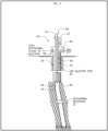
Figure 1 is an illustration of a downhole heat exchanger which may be used in a system according to embodiments herein. -
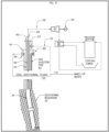
Figure 2 is a process flow diagram of a system for producing thermal or electrical power from a geothermal reservoir according to embodiments herein not making part of the claimed subject-matter. -
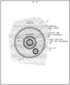
Figure 3 is a process flow diagram of a system for producing thermal or electrical power from a geothermal reservoir according to embodiments herein not making part of the claimed subject-matter.Figure 3A is a cross section of the wellbore and downhole heat exchanger ofFigure 3 including a gas injection pipe. -
Figure 4 is a process flow diagram of a system for producing power or electricity from a geothermal reservoir according to embodiments herein not making part of the claimed subject-matter. -
Figure 5 is a process flow diagram of a system for producing power or electricity from a geothermal reservoir according to embodiments herein not making part of the claimed subject-matter. -
Figure 6 is a process flow diagram of a system for producing power or electricity from a geothermal reservoir according to embodiments herein not making part of the claimed subject-matter. -
Figure 7 is a process flow diagram of a system for producing power or electricity from a geothermal reservoir according to embodiments herein not making part of the claimed subject-matter. -
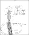
Figure 8 is an illustration of a well including a blocked annular region for efficient use of steam collected from a geothermal reservoir by a system and process for producing working fluid and generating thermal or electrical power from a geothermal reservoir containing steam according to embodiments herein. - In a geothermal reservoir, the hot fluids are generally under tremendous pressure, the source of this pressure being the rock overburden (lithostatic pressure), the water table (hydrostatic pressure), or some combination of the two. As geothermal fluid comprised of steam and/or brine is produced from a geothermal reservoir via a well, it undergoes a reduction in pressure. Indeed, this pressure difference is what propels the geothermal steam or brine to the surface. Depending on the pressure and the enthalpy of the steam or brine, it may expand or flash to a vapor as it rises up the well. While this does not adversely affect the enthalpy of the produced fluid, it does result in a decreased temperature of the produced mixture of steam and brine. If a heat exchanger only at the surface is used to transfer this heat into a separate working fluid, as is typically used in binary systems, the working fluid cannot be made hotter than the brine and steam temperature at the surface. This limits how much power can be produced.
- By inserting a downhole heat exchanger (DHX) into a geothermal well, higher geothermal steam and brine temperatures at depth can be accessed by the heat exchanger. This allows the working fluid circulating in the DHX to be able to produce more power than if the heat exchanger was located at the surface.
- While accessing higher temperatures with a DHX that exists downhole is required in some embodiments of this invention, a consequence of inserting the DHX is that the produced brine will not flash, or will not flash as much, as it ascends toward the surface. The transfer of heat to the DHX will cause the production fluid in the well to become cooler and denser, causing a heavier column weight, potentially stopping (or killing) the upward flow of fluid in the well. To prevent or reverse this, such wells can be stimulated, either continuously or as needed, by either gas lifting, through the use of submersible pumps, or a combination of these mechanisms.
- In one embodiment not making part of the present invention, there is provided a method for producing a higher-pressure flow of the heated geothermal production fluid from the well. The method of this embodiment comprises: (a) gas lifting the geothermal production fluid around the outside of the DHX installed into the well; (b) pumping a separate high-pressure working fluid to circulate inside the DHX; (c) transferring heat from the geothermal production fluid, as it is produced, to the circulating working fluid inside the DHX; and (d) using the high-pressure working fluid from inside the DHX to produce power. The simultaneous production of the production fluid, circulation of the working fluid in the DHX, and the heat transfer from the production fluid to the working fluid in the DHX is referred to herein as "coproduction."
- In another embodiment not making part of the present invention, there is provided a method for coproducing a flow of production and working fluids such that NCGs in the geothermal steam and brine do not come into contact with equipment on the surface that would be negatively affected by such NCGs. The method of this embodiment comprises: (a) gas lifting the geothermal production fluid containing NCGs around the outside of a DHX installed into the well; (b) pumping a separate high-pressure working fluid inside the DHX; (c) transferring heat from the geothermal production fluid, as it is produced, to the circulating working fluid inside the DHX; and (d) using the high-pressure working fluid from inside the DHX to produce thermal or electrical power.
- In another embodiment not making part of the present invention, there is provided a method for utilizing NCGs preexisting in the geothermal production fluid brought to the surface or adding NCGs to the geothermal production fluid to further enhance the flow of the geothermal production fluid produced by the well. The method of this embodiment comprises: (a) gas lifting the geothermal production fluid; (b) removing NCGs from the geothermal production fluid brought to the surface; and (c) adding all or a portion of the removed NCGs to the system used to gas lift the geothermal production fluid such that all or a portion of such NCGs are recycled to assist in the gas lift.
- In yet another embodiment not making part of the present invention, there is provided a system to extract enthalpy from a geothermal production fluid using a second fluid as the working fluid circulating in a DHX. The DHX system of this embodiment comprises: (a) a tube-in-tube heat exchanger, having (i) an outer tube that is plugged at the bottom and (ii) an insulated tube that is inserted inside the outer tube to return the working fluid to the surface; (b) a pump to provide flow to the circulating working fluid; (c) a flash-tank collector to provide phase separation of the working fluid at the surface (if needed); (d) an offtake system to deliver the gas portion of the working fluid to a turbine to make thermal or electrical power; and (e) a liquid supply of makeup working fluid.
- In some embodiments, the coproduced fluid is produced to the surface. For example, the coproduced fluid delivered to the surface may have sufficient pressure to match or exceed the plant system pressure even after heat transfer to a DHX, if present. However, whether or not the plant system pressure is matched or exceeded, a surface heat exchanger (SHX) may be used to capture additional heat from the coproduced fluid in the working fluid that will not contain NCGs, simultaneously separating out the NCGs that often limit power production. The SHX may transfer heat from the coproduced geothermal brine or production fluid to the same working fluids as contemplated for the DHX, such as water, a hydrocarbon, or a refrigerant, and thereafter may use the working fluid from the SHX to produce thermal or electric power. As a gas lift, for example, may be used to deliver higher temperature and pressure production fluid to the SHX, the system may make use of a SHX more efficient or practical in integrating with an existing surface power production plant system. In some embodiments, the SHX may be used to pre-heat, or add supplemental heat to, the working fluid provided to the DHX.
- In embodiments of the present invention, the coproduced fluid, such as steam, is not produced to the surface but, instead, is blocked from reaching the surface and the steam is condensed on the cooler DHX at depth with the liquid condensate flowing down to return to the geothermal resource after transferring heat to the working fluid in the DHX. The method of this embodiment comprises: (a) one or more plugs or barriers around the outside of a DHX at depth to prevent steam from rising to the surface in the annulus around the outer conduit of the DHX; (b) steam from the geothermal resource penetrating the well through a slotted liner and condensing on the cooler outer conduit of the DHX with the resulting liquid brine flowing downward to replenish the resource, induce advective steam flow into the well and, where applicable, establish a convective loop of fluid circulating downward in the conduit surrounding the DHX and upward in the geothermal resource to re-enter the conduit surrounding the DHX after having been reheated by the resource; and (c) transferring heat from the steam production fluid and condensate to the circulating working fluid inside the DHX; and (d) using the working fluid from inside the DHX to produce thermal or electrical power.
- In still other embodiments not making part of the invention, the produced fluid may be produced to the surface using a gas lift. It has been found that the produced fluid delivered to the surface, when using a gas lift to continuously stimulate flow from the well, may have sufficient pressure to match or exceed the plant system pressure. However, whether or not the plant system pressure is matched or exceeded, a surface heat exchanger (SHX) may be used in addition to or in lieu of a DHX to capture heat from the coproduced fluid. The SHX may transfer heat from the produced geothermal brine or production fluid to a working fluid, and thereafter may use the working fluid from the SHX to produce thermal or electric power. The gas used for the gas lift may be a variety of gases, including, without limitation, NCGs that have been recovered from the geothermal brine produced to the surface. Additionally, the gas lift gas may be conditioned by adding water or other fluids to add mass and force to the lift process and reduce the parasitic load of power required to pressurize the gas to optimally lift the co-produced fluid. The gas lift may deliver higher temperature and pressure production fluid to the SHX, allowing the system to make use of a SHX to extract the energy from the produced fluid, allowing a SHX to be used in addition to or in lieu of a DHX in various embodiments. In this manner, the SHX may isolate the lift gas or other NCGs in the produced fluid, so that such do not interact with the turbine.
- In sum, the present invention includes novel apparatus and methods of bringing a working fluid to the surface with a higher temperature than the steam or brine comprising the production fluid that is superior to existing geothermal technologies. Various combinations of a SHX and/or DHX inserted into wells that circulate appropriate working fluids in a closed loop together with various production fluid lift methods and/or recirculation methods may be used to substantially increase the production of thermal or electrical power.
- In some examples, the working fluid is water, which can be flashed to a precise lower pressure upon leaving the DHX. Once flashed, usually the resulting stream is a mixture of both steam and liquid, which are separated in a flash vessel. The steam portion is directed into the steam delivery and power generation systems of a geothermal power plant, with the steam delivery pressure matched to the requirements of the plant. The liquid portion is combined with fresh makeup water and recycled back into the DHX.
- In another example, the working fluid is the produced brine. After deaerating the produced brine to remove NCGs or other undesirable components, the brine can be pressurized and directed to the DHX. When it exits the DHX it can be flashed, with the steam portion delivered to the existing geothermal power plant at the required system pressure. The liquid portion is recycled back into the DHX.
- In another example, the working fluid is water. When the water exits the DHX, the heat is transferred to a power generation system through a second heat exchanger at the surface. The heat exchanger at the surface may be part of an organic Rankine cycle power system, many of which are available commercially or already present and at geothermal power plants.
- In still another example, the working fluid can be an organic hydrocarbon, refrigerant, or an inorganic fluid, and power can be produced directly from the working fluid as it exits the DHX and expands through a turbine or expander, before being cooled and reinjected into the DHX.
- Referring now to
Figure 1 , a schematic illustration of the DHX is illustrated. The well drilled into the geological formation 10 (geothermal formation 10) may include a well casing 12 for producingfluids 14 from the geothermal formation. Within thewell casing 12 is disposed aheat exchanger 16 for indirectly heating a working fluid with the hot produced fluids. - The heat exchanger in some embodiments is a tube-in-tube heat exchanger, and may include an outer
heat exchange conduit 18 and aninner conduit 20. Cool workingfluid 22 is circulated through the annulus, between the outerheat exchange conduit 18 and theinner conduit 20, to a terminal or capped end (not shown) of the outer heat exchange conduit and thence into an open end (not shown) of theinner conduit 20. During circulation through the outer heat exchange conduit, the working fluid is heated by indirect heat exchange with thefluids 14 being produced from the formation. A heated workingfluid 24 may then be recovered via the inner conduit. The direction of the working fluid may also be reversed. - Such a DHX may be used to produce thermal or electrical power from the geothermal formation. Embodiments of such systems are illustrated in
Figures 2-8 , where like numerals represent like parts. - Referring now to
Figure 2 , a system for producing thermal or electrical power from a geothermal reservoir is illustrated. Awellbore 30 may be drilled into ageothermal reservoir 32, and may include one or more sections of a production conduit orcasing 34. Adownhole heat exchanger 40 may be disposed within theproduction conduit 34, and may include an outerheat exchange conduit 44 and aninner conduit 46, similar to the tube-in-tube heat exchanger described with respect toFigure 1 . The DHX may extend from thewellhead assembly 42 through thecasing 34 to a desired depth, such as above, proximate, or into thegeothermal reservoir 32. - Working
fluid 52 is circulated into the DHX viainlet 53, through the annulus, between the outerheat exchange conduit 44 and theinner conduit 46, to a terminal or cappedend 54 of the outerheat exchange conduit 44 and thence into anopen end 56 of theinner conduit 46. During circulation through the outerheat exchange conduit 44, the working fluid is heated by indirect heat exchange with the hot geothermal fluids being produced from the formation and traversing upward through theproduction conduit 34. The direction of the working fluid may also be reversed. The produced fluids are correspondingly cooled via the indirect heat exchange and recovered via a producedfluids outlet 58. - The produced fluids may be further processed, if desired, and/or injected into the reservoir. In some embodiments, such as where the produced fluid contains sufficient residual energy, additional energy may be extracted from the produced fluids and converted into power or electricity, such as via a second energy conversion system (not illustrated), which may include heat exchangers, turbines and other associated equipment for recovering the residual energy contained in the produced fluids.
- The working fluid is gradually heated as it traverses downhole, and a heated working
fluid 59 may then enter and traverse through theinner conduit 46, which may be insulated, and be recovered via heated workingfluid outlet 60. - Energy transferred to the working fluid in the form of heat may then be utilized by an energy conversion system or may be converted via an energy conversion system, which may include a
turbine 62, for example, to produce power orelectricity 64. The expanded workingfluid 66 may then be cooled, such as via indirect heat exchange within one or more of a feed /effluent exchanger 68,cooling towers 70, or other direct or indirect heat exchange mechanisms (not shown). - Circulation of the working fluid may be provided via a working fluid circulation system. The working fluid circulation system may include a
pump 72, valves (not illustrated), associated piping, and other components (temperature and pressure sensors, for example; not shown). - In some embodiments, the working fluid circulation system does not include or require a pump. Rather, the diameters of the DHX and associated components may be configured such that the selected working fluid circulates through the system via a thermosiphon effect.
- As noted above, the ability to produce thermal or electrical power, from lower pressure, higher flow geothermal fluids, is desirable. Further, reservoir characteristics may be such that the cooling of the produced fluids, as it (a) rises to the surface and (b) heats the working fluid, may result in decreased flow or may effectively stop production of fluids from the reservoir due to changes in temperature, pressure and density of the produced fluids.
- In some embodiments, systems for producing thermal or electrical power from geothermal reservoirs may include an artificial lift mechanism to aid in the transport of the hot produced fluids from the geothermal reservoir across the DHX and to the surface.
- As illustrated in
Figure 3 , the artificial lift mechanism may include a gas lift. Alift gas 80 may be introduced via gaslift injector pipe 82. The gas lift pipe may extend within the wellbore to a depth equivalent to or below thelower end 54 ofDHX 40, the lift gas exiting theterminal end 84 of the gaslift injector pipe 82, thereby enhancing the flow of produced fluids from the geothermal reservoir to the surface, and increasing the heat transferred to the working fluid withinDHX 40. The lift gas may be introduced via one or more gas distributors, which may be disposed at one or more elevations within the wellbore. - As illustrated in
Figure 3A , the gaslift injector pipe 90 may traverse downhole within the annulus formed between theDHX 40 and thecasing 34. Alternative means for injecting a lift gas into the wellbore may also be used. - Gas lift is commonly used in geothermal systems to "kick off," or start a non-flowing well. However, as soon as hot water and steam get to the surface, the column of water is light enough to continue the flow without gas assist. In contrast, systems disclosed herein may use a continuous, or intermittent as needed, gas lift to aid in the transport of the hot produced fluids from the geothermal reservoir to the surface to maintain flow of the coproduced geothermal fluid and avoiding the possibility of "killing" the well as previously described.
- As noted above, the produced fluids may be further processed, if desired, and/or injected into the reservoir. It has been found that when using a gas lift, such as described above with respect to
Figures 3 and3A , the produced fluid delivered to the surface may have sufficient pressure to match or exceed the system plant pressure, and may contain sufficient residual energy for it to be extracted from the produced fluids and converted into power or electricity, such as via a second energy conversion system (not illustrated). The second energy conversion system may include heat exchangers, turbines and other associated equipment for recovering the residual energy contained in the produced fluids. - Alternatively, or additionally, as illustrated in
Figure 4 , the artificial lift mechanism may include a submergedpump 90. The submergedpump 90 may be disposed within the wellbore at a depth below thelower end 54 ofDHX 40, pumping produced fluids toward the surface, and thereby enhancing the flow of produced fluids from the geothermal reservoir to the surface, and increasing the heat transferred to the working fluid withinDHX 40. - In some embodiments, the working fluid comprises water. In other embodiments, the working fluid may be a light hydrocarbon or refrigerant. In yet other embodiments, the working fluid may be carbon dioxide. In other embodiments, the working fluid may comprise the produced fluid or a portion thereof.
- In each case, the working fluid may be in various or mixed phases. The working fluid may be partially or completely vaporized due the heat exchange within the DHX. In other embodiments, the working fluid may remain pressurized sufficiently such that the working fluid remains as a liquid or in its supercritical phase when recovered at the surface. As shown in
Figure 5 , prior to passing the working fluid across a turbine, for example, the heated workingfluid 59 may be passed through avessel 108, such as a flash vessel or separator, to produce thevapors 110 that may be used to rotate a turbine or similarly used at apower plant 112. Thenon-vaporized liquids 114 may then be drawn from thevessel 108 and recirculated through the DHX viapump 72. As needed, additional workingfluid 116 may be added to form the workingfluid 52 injected into theDHX 40. - As noted above, in some embodiments the working fluid may include produced fluids. As illustrated in
Figure 6 , a produced fluid, such as a produced brine, may be circulated into the DHX viaflow line 120. As needed, additional workingfluid 116, or makeup water or brine where the working fluid is a brine, may be added to form the workingfluid 52 injected into theDHX 40. In this manner, the loss in energy normally associated with the production of the produced fluid may be enhanced by the DHX to advantageously produce energy from the produced fluid. - Produced fluids often contain dissolved gases that may separate from the liquids in the produced fluids at the lower surface pressures. In such embodiments, depending upon the composition and usefulness of such gases to produce energy via heating in the DHX, it may be desirable to separate the dissolved gases from the produced fluids prior to feeding the produced fluids to the DHX.
- As illustrated in
Figure 7 , the produced fluids may be fed viaflow line 120 to aseparator 130 to separate the dissolvedgases 132 from theliquids 134 in the produced fluids. The recoveredgases 132 may be vented or otherwise processed, as needed or required. Theliquids 134 may then be fed to the DHX, along with any makeup water orbrine 116, for heating in the DHX. Similar to the embodiment ofFigure 6 , in this manner, the loss in energy normally associated with the production of the produced fluid may be enhanced by the DHX to advantageously produce energy from the produced fluid. - In other embodiments, the annular region around a portion of the DHX may be blocked or otherwise restrict flow of produced steam. The blocked region may allow the produced steam to collect and condense as it transfers heat to the DHX. The liquid condensate may then descend down the annular region surrounding the DHX for return to the geothermal formation.
- Referring now to
Figure 8 , a system for producing working fluid and generating thermal or electrical power from a geothermal reservoir containing steam, where the system includes one or more plugs or barriers to create such a blocked annular region surrounding the DHX, is illustrated, in accordance with embodiments of the claimed subject-matter. Similar toFigure 2 , the system includes anouter production conduit 34, which includes a lined well or hole open to the reservoir, as well as aDHX 40 disposed within theouter production conduit 34. The DHX includes an outerheat exchange conduit 44 and aninner conduit 46. A working fluid circulation system (72, 52, etc.) for circulating a working fluid through the outerheat exchange conduit 44 and into the inner conduit 46 (or in the opposite direction) is also provided. - Steam produced from
geothermal reservoir 32 may be collected withinproduction conduit 34, and then come into contact withDHX 40. A system of one ormore plugs 150 or other barriers is disposed in the annulus between the well 34 and theouter conduit 44 ofDHX 40. Theplugs 150 prevent steam from rising up the annulus around theouter conduit 44 inzone 152. Rather, heat is efficiently extracted viaDHX 40 proximate the lower end thereof, condensing water at the surface of theouter conduit 44 of the heat exchanger. - Similarly, steam produced from
geothermal reservoir 32 may be collected within the annulus between a slotted liner 154 and the DHX, and then come into contact withDHX 40. A system of one ormore plugs 150 or other barriers are disposed in the annulus between thewell casing 34 and theouter conduit 44 ofDHX 40. Theplugs 150 prevent steam from rising up the annulus around theouter conduit 44 inzone 152. Rather, heat is efficiently extracted viaDHX 40 proximate the lower end thereof, condensing water at the surface of theouter conduit 44 of the heat exchanger. Condensate will descend downwards and will escape to the reservoir. In some embodiments, this flow of condensed steam to deeper in the reservoir and adding advection heating will set up a convection loop of water circulating up in the resource and down in the conduit, such as a slotted liner 154, surrounding the heat exchanger, as illustrated inFigure 8 . - A system for controlling the flow rate of the working fluid in the heat exchanger may also be provided. The controller is configured to maintain the flow rate of the working fluid within a range that produces a desired amount of energy to an energy conversion or utilization system, such as a
turbine 72, while also resulting in steam condensing into water at the surface ofouter conduit 44 of the heat exchanger, causing a significant density difference and resulting in the condensed steam flowing deeper into the reservoir, thereby causing steam to flow from deeper in the geothermal resource towards the conduit, adding advection heating to the conduction heating. The condensed steam will flow back into the geothermal reservoir. The energy utilization or conversion system, such asturbine 62, may be used for using or converting energy contained in the heated working fluid recovered fromDHX 40 at the surface for thermal or electrical power, for example. - The area above plugs or
barriers 150, withinzone 152, may be empty, or in some embodiments, may be a system of gas, insulation or other fill material (not shown) installed within the annular region between the casing 34 of the well or open borehole andouter conduit 44 of theDXH 40. The plugs orbarriers 150 prevent steam from rising to the surface, and the fill material may insulate the heat exchanger from the geothermal resource and/or may be used to reduce the potential for steam from the geothermal resource to condense against the heat exchanger above such plugs or other barriers and becoming corrosive due to chemical reactions of superheated steam with condensed steam. - In other aspects, embodiments disclosed herein relate to a process for producing working fluid and generating thermal or electrical power from a geothermal reservoir containing steam. In some embodiments, the processes may include steps for operating the systems as illustrated and described with respect to
Figures 1-8 ; of whichFigure 8 shows an embodiment in accordance with the claimed subject-matter. - Processes herein also include disposing a heat exchanger within an outer production conduit, such as a lined well or hole open to the reservoir. According to the present disclosure, one or more plugs or other barriers are disposed in the annulus between the well and the outer conduit of the heat exchanger. Additionally, installing gas, insulation or other fill material may be disposed or installed between the casing of the well or open borehole and the outer conduit of the heat exchanger above the plugs of other barriers. The heat exchanger includes an outer heat exchange conduit and an inner conduit.
- The process of generating power includes circulating a working fluid through the outer heat exchange conduit and into the inner conduit, or vice versa (through the inner conduit into the outer conduit). The rate of flow of the working fluid in the heat exchanger is controlled, such that steam condenses into water at the surface of the outer conduit of the heat exchanger, thereby causing a significant density difference resulting in the condensed steam flowing deeper into the reservoir causing steam to flow from deeper in the geothermal resource towards the conduit adding advection heating to the conduction heating.
- The one or more plugs disposed in the annulus between the well and the outer conduit of the heat exchanger prevent steam from rising up the annulus around the outer conduit of the heat exchanger, rather than condensing into water at the surface of the outer conduit of the heat exchanger. The installed gas, insulation or other fill material between the casing of the well or open borehole and outer conduit of the heat exchanger above the plugs of other barriers may prevent steam from rising to the surface, may insulate the heat exchanger from the geothermal resource, and/or may reduce the potential for steam from the geothermal resource to condense against the heat exchanger above such plugs or other barriers and becoming acidic.
- The condensing steam provides heat to the working fluid circulating within the heat exchanger. The process may then utilize or convert the energy contained in the heated working fluid recovered from the heat exchanger at the surface to thermal or electrical power
- Systems for producing fluid and generating power or electricity or other conversion technology from a geothermal reservoir containing dry steam according to embodiments herein include a heat exchanger disposed within the outer production conduit, and include a cased or open hole into the reservoir. The heat exchanger includes, similar to embodiments above, an outer heat exchange conduit and an inner conduit. A working fluid circulation system is provided for circulating a working fluid through the outer heat exchange conduit and into the inner conduit. The system includes a controller that controls the working fluid circulation rate at a rate that results in steam condensing into water at the surface of the outer heat exchanger conduit, causing a significant density difference resulting in the condensed steam flowing deeper into the reservoir causing steam to flow towards the conduit. Such condensation and flow of condensate adds advection heating to the conduction heating in the system, and significantly increases the heat transfer and establishes as convection loop of water and steam circulating from the outer heat exchange conduit into the resource and back again. The system further includes an energy conversion system for converting energy, contained in the heated working fluid recovered from the inner conduit, to power or electricity. In some embodiments, a gas or other fill material between the casing and outer conduit may be used to reduce the potential of steam condensing and becoming acidic due to the reactions of chloride in the superheated steam with condensed steam, resulting in HCl.
- The present description uses numerical ranges to quantify certain parameters relating to the invention. It should be understood that when numerical ranges are provided, such ranges are to be construed as providing literal support for claim limitations that only recite the lower value of the range as well as claims limitation that only recite the upper value of the range. For example, a disclosed numerical range of 10 to 100 provides literal support for a claim reciting "greater than 10" (with no upper bounds) and a claim reciting "less than 100" (with no lower bounds).
- As used herein, the terms "comprising," "comprises," and "comprise" are open-ended transition terms used to transition from a subject recited before the term to one or more elements recited after the term, where the element or elements listed after the transition term are not necessarily the only elements that make up the subject.
- As used herein, the terms "including," "includes, " and "include" have the same open-ended meaning as "comprising, " "comprises, " and "comprise. "
- As used herein, the terms "having," "has, " and "have" have the same open-ended meaning as "comprising, " "comprises," and "comprise. "
- As used herein, the terms "containing," "contains," and "contain" have the same open-ended meaning as "comprising, " "comprises, " and "comprise. "
- As used herein, the terms "a," "an," "the, " and "said" mean one or more.
- As used herein, the term "and/or," when used in a list of two or more items, means that any one of the listed items can be employed by itself or any combination of two or more of the listed items can be employed For example, if a composition is described as containing components A, B, and/or C, the composition can contain A alone; B alone; C alone; A and B in combination; A and C in combination; B and C in combination; or A, B, and C in combination.
- The preferred forms of the invention described above are to be used as illustration only, and should not be used in a limiting sense to interpret the scope of the present invention. Obvious modifications to the exemplary embodiments, set forth above, could be readily made by those skilled in the art without departing from the spirit of the present invention.
- While the disclosure includes a limited number of embodiments, those skilled in the art, having benefit of this disclosure, will appreciate that other embodiments may be devised which do not depart from the scope of the present disclosure. Accordingly, the scope should be limited only by the attached claims.
Claims (5)
- A system for producing working fluid and generating thermal or electrical power from a geothermal reservoir (32) containing steam, the system comprising:an outer production conduit comprised of a lined well (34) or hole open to the reservoir (32);a heat exchanger (40) disposed within the outer production conduit, the heat exchanger (40) comprising an outer heat exchange conduit (44) and an inner heat exchange conduit (46);a working fluid circulation system for circulating a working fluid (52) (a) through the outer heat exchange conduit (44) and into the inner heat exchange conduit (46) or (b) through the inner heat exchange conduit (46) and into the outer heat exchange conduit (44); andan energy utilization or conversion system for using or converting energy contained in the heated working fluid (52) recovered from the heat exchanger (40) at the surface for thermal or electrical power;characterised in that the system further comprisesa measurement and control system for controlling the rate of flow of the working fluid (52) in the heat exchanger (40) configured to result in steam condensing into water at the surface of the outer heat exchange conduit (44) causing a significant density difference resulting in the condensed steam flowing deeper into the reservoir (32) causing steam to flow from deeper in the geothermal resource towards the conduit adding advection heating to the conduction heating;a system of one or more plugs (150) or other barriers disposed in the annulus between the well (34) and the outer heat exchange conduit (44) configured to prevent steam from rising up the annulus around the outer heat exchange conduit (44) rather than condensing into water at the surface of the outer heat exchange conduit (44) below the one or more plugs (150) or barriers.
- The system of claim 1, further comprising a system of gas, insulation or other fill material installed between the casing (12) of the well (34) or open borehole and the outer heat exchange conduit (44) above the one or more plugs (150) or other barriers.
- The system of claim 1, wherein the condensed steam flowing deeper in the reservoir and adding advection heating set up a convection loop of water circulating up in the geothermal resource and down in the outer production conduit.
- The system of claim 1, further comprising a tube inserted between the casing of the well (34) or hole open to the reservoir (32) and the outer heat exchange conduit (44) and pass through the one or more plugs (150) or other barriers to transport any collected non-condensable gases to the surface.
- A process for producing working fluid and generating thermal or electrical power from a geothermal reservoir (32) containing steam, the process comprising:disposing a heat exchanger (40) within an outer production conduit comprised of a lined well (34) or hole open to the reservoir (32), the heat exchanger (40) comprising an outer heat exchange conduit (44) and an inner heat exchange conduit (46);circulating a working fluid (52) through the outer heat exchange conduit (44) and into the inner heat exchange conduit (46) or vice versa;controlling the rate of flow of the working fluid (52) in the heat exchanger (40) such that steam condenses into water at the surface of the outer conduit of the heat exchanger causing a significant density difference resulting in the condensed steam flowing deeper into the reservoir (32) causing steam to flow from deeper in the geothermal resource towards the conduit adding advection heating to the conduction heating;disposing one or more plugs (150) or other barriers in the annulus between the well (34) and the outer heat exchange conduit (44) thereby preventing steam from rising up the annulus around the outer heat exchange conduit (44) rather than condensing into water at the surface of the outer heat exchange conduit (44) of the heat exchanger below the one or more plugs (150) or other barriers;using or converting energy contained in the heated working fluid (52) recovered from the heat exchanger (40) at the surface for thermal or electrical power; andinstalling gas, insulation or other fill material between the casing of the well or open borehole and outer heat exchange conduit (44) above the one or more plugs (150) or other barriers.
Applications Claiming Priority (2)
| Application Number | Priority Date | Filing Date | Title |
|---|---|---|---|
| US201862627809P | 2018-02-08 | 2018-02-08 | |
| PCT/US2019/017296 WO2019157341A1 (en) | 2018-02-08 | 2019-02-08 | Closed loop energy production from producing geothermal wells |
Publications (3)
| Publication Number | Publication Date |
|---|---|
| EP3749907A1 EP3749907A1 (en) | 2020-12-16 |
| EP3749907A4 EP3749907A4 (en) | 2021-10-13 |
| EP3749907B1 true EP3749907B1 (en) | 2025-04-09 |
Family
ID=67548489
Family Applications (1)
| Application Number | Title | Priority Date | Filing Date |
|---|---|---|---|
| EP19750830.2A Active EP3749907B1 (en) | 2018-02-08 | 2019-02-08 | Closed loop energy production from producing geothermal wells |
Country Status (6)
| Country | Link |
|---|---|
| US (1) | US11255576B2 (en) |
| EP (1) | EP3749907B1 (en) |
| JP (1) | JP7135094B2 (en) |
| MX (1) | MX2020008322A (en) |
| PH (1) | PH12020551174A1 (en) |
| WO (1) | WO2019157341A1 (en) |
Families Citing this family (36)
| Publication number | Priority date | Publication date | Assignee | Title |
|---|---|---|---|---|
| CA3044153C (en) | 2018-07-04 | 2020-09-15 | Eavor Technologies Inc. | Method for forming high efficiency geothermal wellbores |
| CA3167574C (en) | 2018-08-12 | 2026-03-17 | Eavor Technologies Inc. | Method for thermal profile control and energy recovery in geothermal wells |
| CA3144627A1 (en) | 2019-06-27 | 2020-12-27 | Eavor Technologies Inc. | Operational protocol for harvesting a thermally productive formation |
| CA3100013C (en) | 2020-04-21 | 2023-03-14 | Eavor Technologies Inc. | Method for forming high efficiency geothermal wellbores using phase change materials |
| WO2022029699A1 (en) | 2020-08-05 | 2022-02-10 | Eavor Technologies Inc. | Generating geothermal energy using multiple working fluids |
| WO2022043947A1 (en) | 2020-08-28 | 2022-03-03 | Eavor Technologies Inc. | Cooling for geothermal well drilling |
| CN113027713A (en) * | 2021-03-25 | 2021-06-25 | 中国科学院广州能源研究所 | Combined geothermal development and utilization system and energy distribution and management method |
| US11592009B2 (en) | 2021-04-02 | 2023-02-28 | Ice Thermal Harvesting, Llc | Systems and methods for generation of electrical power at a drilling rig |
| US11280322B1 (en) | 2021-04-02 | 2022-03-22 | Ice Thermal Harvesting, Llc | Systems for generating geothermal power in an organic Rankine cycle operation during hydrocarbon production based on wellhead fluid temperature |
| US12312981B2 (en) | 2021-04-02 | 2025-05-27 | Ice Thermal Harvesting, Llc | Systems and methods utilizing gas temperature as a power source |
| US11644015B2 (en) | 2021-04-02 | 2023-05-09 | Ice Thermal Harvesting, Llc | Systems and methods for generation of electrical power at a drilling rig |
| WO2022213107A1 (en) * | 2021-04-02 | 2022-10-06 | Ice Thermal Harvesting, Llc | Systems and methods utilizing gas temperature as a power source |
| US11293414B1 (en) | 2021-04-02 | 2022-04-05 | Ice Thermal Harvesting, Llc | Systems and methods for generation of electrical power in an organic rankine cycle operation |
| US11486370B2 (en) | 2021-04-02 | 2022-11-01 | Ice Thermal Harvesting, Llc | Modular mobile heat generation unit for generation of geothermal power in organic Rankine cycle operations |
| US11480074B1 (en) | 2021-04-02 | 2022-10-25 | Ice Thermal Harvesting, Llc | Systems and methods utilizing gas temperature as a power source |
| US11421663B1 (en) | 2021-04-02 | 2022-08-23 | Ice Thermal Harvesting, Llc | Systems and methods for generation of electrical power in an organic Rankine cycle operation |
| US11493029B2 (en) | 2021-04-02 | 2022-11-08 | Ice Thermal Harvesting, Llc | Systems and methods for generation of electrical power at a drilling rig |
| US11326550B1 (en) | 2021-04-02 | 2022-05-10 | Ice Thermal Harvesting, Llc | Systems and methods utilizing gas temperature as a power source |
| WO2022269305A1 (en) * | 2021-06-22 | 2022-12-29 | Totalenergies Onetech | Process for producing energy in a hydrocarbon production installation and related hydrocarbon production installation |
| CN113639477A (en) * | 2021-09-15 | 2021-11-12 | 中核坤华能源发展有限公司 | Medium-low temperature geothermal water recharging system and method |
| WO2023049454A1 (en) * | 2021-09-27 | 2023-03-30 | Sage Geosystems Inc. | Downhole heat exchanger for geothermal power systems |
| CN114412416B (en) * | 2022-03-09 | 2025-06-27 | 山东省鲁南地质工程勘察院(山东省地质矿产勘查开发局第二地质大队) | A geothermal heat reservoir and transmission pipeline non-pump descaling device and use method |
| CZ2022179A3 (en) * | 2022-05-03 | 2023-05-17 | Jiří MÁLEK | Cryogenic geothermal engine |
| CN114689647A (en) * | 2022-05-27 | 2022-07-01 | 山东省地质矿产勘查开发局八〇一水文地质工程地质大队(山东省地矿工程勘察院) | Heat convection type geothermal field development and protection simulation system and simulation method |
| CN115711496A (en) * | 2022-11-17 | 2023-02-24 | 天津大学 | Direct-expansion type underground heat exchanger for reinforced heat exchange of geothermal single well and heat exchange system |
| US12158138B2 (en) * | 2022-12-05 | 2024-12-03 | Mark H. Taylor | Renewable geothermal energy harvesting systems and methods |
| CN115961906B (en) * | 2022-12-15 | 2024-02-27 | 江苏雄越石油机械设备制造有限公司 | Extra-high voltage wellhead device |
| US12534990B2 (en) | 2022-12-29 | 2026-01-27 | Ice Thermal Harvesting, Llc | Power generation assemblies for hydraulic fracturing systems and methods |
| US12180861B1 (en) | 2022-12-30 | 2024-12-31 | Ice Thermal Harvesting, Llc | Systems and methods to utilize heat carriers in conversion of thermal energy |
| FR3139380B1 (en) * | 2023-08-01 | 2025-09-05 | Cgg Services Sas | SYSTEM AND METHOD FOR THE EXTRACTION OF ENERGY AND RESOURCES WITH REDUCED EMISSIONS |
| WO2025074160A1 (en) * | 2023-10-06 | 2025-04-10 | Stoic Transitional Resources, Inc. | Geothermal energy system |
| CN117267968B (en) * | 2023-10-16 | 2024-08-06 | 天津大学 | A dry hot rock single well open forced circulation high efficiency heat extraction system |
| WO2025101967A1 (en) * | 2023-11-08 | 2025-05-15 | Greenfire Energy Inc. | Methods and systems for installing tubulars in wells |
| GB2636831A (en) | 2023-12-22 | 2025-07-02 | Micro Thermal Energy Ltd | Heat exchanger |
| US20250297785A1 (en) * | 2024-03-25 | 2025-09-25 | Greenfire Energy Inc. | Methods and systems for heat transfer using formation fluids |
| US12516850B1 (en) | 2024-08-14 | 2026-01-06 | Mark H. Taylor | Renewable geothermal energy harvesting from offshore wells and methods |
Family Cites Families (17)
| Publication number | Priority date | Publication date | Assignee | Title |
|---|---|---|---|---|
| US4364232A (en) * | 1979-12-03 | 1982-12-21 | Itzhak Sheinbaum | Flowing geothermal wells and heat recovery systems |
| US4328673A (en) * | 1980-08-25 | 1982-05-11 | Sperry Corporation | Geothermal pump dual cycle system |
| JPS57124078A (en) * | 1981-01-27 | 1982-08-02 | Hitachi Ltd | Heat generator |
| US6073448A (en) * | 1998-08-27 | 2000-06-13 | Lozada; Vince M. | Method and apparatus for steam generation from isothermal geothermal reservoirs |
| US7347059B2 (en) | 2005-03-09 | 2008-03-25 | Kelix Heat Transfer Systems, Llc | Coaxial-flow heat transfer system employing a coaxial-flow heat transfer structure having a helically-arranged fin structure disposed along an outer flow channel for constantly rotating an aqueous-based heat transfer fluid flowing therewithin so as to improve heat transfer with geological environments |
| WO2009072364A1 (en) | 2007-12-06 | 2009-06-11 | Hachiyo Engineering Co., Ltd. | Geothermal apparatus |
| US8985221B2 (en) | 2007-12-10 | 2015-03-24 | Ngsip, Llc | System and method for production of reservoir fluids |
| US20120018120A1 (en) * | 2009-05-14 | 2012-01-26 | Danko George L | Geothermal energy extraction system and method |
| US20110232858A1 (en) | 2010-03-25 | 2011-09-29 | Hiroaki Hara | Geothermal well using graphite as solid conductor |
| EP2632616A2 (en) * | 2010-10-25 | 2013-09-04 | TPS Technologies | Devices and methods for soil remediation |
| EP2649311B1 (en) | 2010-12-10 | 2018-04-18 | Schwarck Structure, LLC | Passive heat extraction and power generation |
| US20140206912A1 (en) * | 2011-05-03 | 2014-07-24 | The Administrators Of The Tulane Educational Fund | Underground reactor system |
| US9006297B2 (en) | 2012-06-16 | 2015-04-14 | Robert P. Herrmann | Fischer tropsch method for offshore production risers for oil and gas wells |
| US9388797B2 (en) * | 2012-09-14 | 2016-07-12 | Ormat Technologies, Inc. | Method and apparatus for producing power from geothermal fluid |
| JP2014084857A (en) | 2012-10-28 | 2014-05-12 | Yasuharu Kawabata | Binary power generation system |
| WO2015066764A1 (en) * | 2013-11-06 | 2015-05-14 | Controlled Thermal Technologies Pty Ltd | Geothermal loop in-ground heat exchanger for energy extraction |
| US20150330670A1 (en) | 2014-05-16 | 2015-11-19 | Richard L. Wynn, Jr. | System and method for utilizing oil and gas wells for geothermal power generation |
-
2019
- 2019-02-08 JP JP2020542892A patent/JP7135094B2/en active Active
- 2019-02-08 WO PCT/US2019/017296 patent/WO2019157341A1/en not_active Ceased
- 2019-02-08 US US16/968,370 patent/US11255576B2/en active Active
- 2019-02-08 EP EP19750830.2A patent/EP3749907B1/en active Active
- 2019-02-08 MX MX2020008322A patent/MX2020008322A/en unknown
-
2020
- 2020-08-03 PH PH12020551174A patent/PH12020551174A1/en unknown
Also Published As
| Publication number | Publication date |
|---|---|
| EP3749907A4 (en) | 2021-10-13 |
| WO2019157341A1 (en) | 2019-08-15 |
| US20210062682A1 (en) | 2021-03-04 |
| JP2021513620A (en) | 2021-05-27 |
| PH12020551174A1 (en) | 2021-05-31 |
| US11255576B2 (en) | 2022-02-22 |
| JP7135094B2 (en) | 2022-09-12 |
| EP3749907A1 (en) | 2020-12-16 |
| MX2020008322A (en) | 2020-09-21 |
Similar Documents
| Publication | Publication Date | Title |
|---|---|---|
| US11255576B2 (en) | Closed loop energy production from producing geothermal wells | |
| JP7516306B2 (en) | Process and method for generating geothermal heat | |
| US4364232A (en) | Flowing geothermal wells and heat recovery systems | |
| US4054176A (en) | Multiple-completion geothermal energy production systems | |
| US5515679A (en) | Geothermal heat mining and utilization | |
| US3957108A (en) | Multiple-completion geothermal energy production systems | |
| US4044830A (en) | Multiple-completion geothermal energy production systems | |
| US4201060A (en) | Geothermal power plant | |
| US8430166B2 (en) | Geothermal energy extraction system and method | |
| US8650875B2 (en) | Direct exchange geothermal refrigerant power advanced generating system | |
| US9394771B2 (en) | Single well, self-flowing, geothermal system for energy extraction | |
| US8201409B1 (en) | Closed loop, hot dry rock heat recovery fluid | |
| US20150330670A1 (en) | System and method for utilizing oil and gas wells for geothermal power generation | |
| US4512155A (en) | Flowing geothermal wells and heat recovery systems | |
| US20120018120A1 (en) | Geothermal energy extraction system and method | |
| JPS6042358B2 (en) | Geothermal energy recovery method and device | |
| EP2612028B1 (en) | A power generation system | |
| HUP0301960A2 (en) | Method and system for exchanging earth energy between earthly bodies and an energy exchanger, especially to produce an electric current | |
| US4051677A (en) | Multiple-completion geothermal energy production systems | |
| US20050205260A1 (en) | Wellbore rig with heat transfer loop apparatus | |
| JP5839531B1 (en) | Geothermal exchanger and geothermal power generator | |
| JP2016164395A (en) | Geothermal power generation system and geothermal power generation method | |
| US8418465B2 (en) | Geothermal heat transfer and intensification system and method | |
| WO2024123376A1 (en) | Renewable geothermal energy harvesting systems and methods | |
| RU2375559C1 (en) | Oil production method |
Legal Events
| Date | Code | Title | Description |
|---|---|---|---|
| STAA | Information on the status of an ep patent application or granted ep patent |
Free format text: STATUS: THE INTERNATIONAL PUBLICATION HAS BEEN MADE |
|
| PUAI | Public reference made under article 153(3) epc to a published international application that has entered the european phase |
Free format text: ORIGINAL CODE: 0009012 |
|
| STAA | Information on the status of an ep patent application or granted ep patent |
Free format text: STATUS: REQUEST FOR EXAMINATION WAS MADE |
|
| 17P | Request for examination filed |
Effective date: 20200828 |
|
| AK | Designated contracting states |
Kind code of ref document: A1 Designated state(s): AL AT BE BG CH CY CZ DE DK EE ES FI FR GB GR HR HU IE IS IT LI LT LU LV MC MK MT NL NO PL PT RO RS SE SI SK SM TR |
|
| AX | Request for extension of the european patent |
Extension state: BA ME |
|
| DAV | Request for validation of the european patent (deleted) | ||
| DAX | Request for extension of the european patent (deleted) | ||
| A4 | Supplementary search report drawn up and despatched |
Effective date: 20210914 |
|
| RIC1 | Information provided on ipc code assigned before grant |
Ipc: F24T 10/00 20180101ALI20210908BHEP Ipc: F01K 23/02 20060101ALI20210908BHEP Ipc: F24T 10/20 20180101ALI20210908BHEP Ipc: F28D 20/00 20060101AFI20210908BHEP |
|
| GRAP | Despatch of communication of intention to grant a patent |
Free format text: ORIGINAL CODE: EPIDOSNIGR1 |
|
| STAA | Information on the status of an ep patent application or granted ep patent |
Free format text: STATUS: GRANT OF PATENT IS INTENDED |
|
| INTG | Intention to grant announced |
Effective date: 20241217 |
|
| GRAS | Grant fee paid |
Free format text: ORIGINAL CODE: EPIDOSNIGR3 |
|
| GRAA | (expected) grant |
Free format text: ORIGINAL CODE: 0009210 |
|
| STAA | Information on the status of an ep patent application or granted ep patent |
Free format text: STATUS: THE PATENT HAS BEEN GRANTED |
|
| AK | Designated contracting states |
Kind code of ref document: B1 Designated state(s): AL AT BE BG CH CY CZ DE DK EE ES FI FR GB GR HR HU IE IS IT LI LT LU LV MC MK MT NL NO PL PT RO RS SE SI SK SM TR |
|
| REG | Reference to a national code |
Ref country code: GB Ref legal event code: FG4D |
|
| REG | Reference to a national code |
Ref country code: CH Ref legal event code: EP |
|
| REG | Reference to a national code |
Ref country code: DE Ref legal event code: R096 Ref document number: 602019068415 Country of ref document: DE |
|
| REG | Reference to a national code |
Ref country code: IE Ref legal event code: FG4D |
|
| REG | Reference to a national code |
Ref country code: NL Ref legal event code: MP Effective date: 20250409 |
|
| PG25 | Lapsed in a contracting state [announced via postgrant information from national office to epo] |
Ref country code: NL Free format text: LAPSE BECAUSE OF FAILURE TO SUBMIT A TRANSLATION OF THE DESCRIPTION OR TO PAY THE FEE WITHIN THE PRESCRIBED TIME-LIMIT Effective date: 20250409 |
|
| REG | Reference to a national code |
Ref country code: AT Ref legal event code: MK05 Ref document number: 1783849 Country of ref document: AT Kind code of ref document: T Effective date: 20250409 |
|
| PG25 | Lapsed in a contracting state [announced via postgrant information from national office to epo] |
Ref country code: FI Free format text: LAPSE BECAUSE OF FAILURE TO SUBMIT A TRANSLATION OF THE DESCRIPTION OR TO PAY THE FEE WITHIN THE PRESCRIBED TIME-LIMIT Effective date: 20250409 Ref country code: PT Free format text: LAPSE BECAUSE OF FAILURE TO SUBMIT A TRANSLATION OF THE DESCRIPTION OR TO PAY THE FEE WITHIN THE PRESCRIBED TIME-LIMIT Effective date: 20250811 Ref country code: ES Free format text: LAPSE BECAUSE OF FAILURE TO SUBMIT A TRANSLATION OF THE DESCRIPTION OR TO PAY THE FEE WITHIN THE PRESCRIBED TIME-LIMIT Effective date: 20250409 |
|
| REG | Reference to a national code |
Ref country code: LT Ref legal event code: MG9D |
|
| PG25 | Lapsed in a contracting state [announced via postgrant information from national office to epo] |
Ref country code: NO Free format text: LAPSE BECAUSE OF FAILURE TO SUBMIT A TRANSLATION OF THE DESCRIPTION OR TO PAY THE FEE WITHIN THE PRESCRIBED TIME-LIMIT Effective date: 20250709 Ref country code: GR Free format text: LAPSE BECAUSE OF FAILURE TO SUBMIT A TRANSLATION OF THE DESCRIPTION OR TO PAY THE FEE WITHIN THE PRESCRIBED TIME-LIMIT Effective date: 20250710 |
|
| PG25 | Lapsed in a contracting state [announced via postgrant information from national office to epo] |
Ref country code: PL Free format text: LAPSE BECAUSE OF FAILURE TO SUBMIT A TRANSLATION OF THE DESCRIPTION OR TO PAY THE FEE WITHIN THE PRESCRIBED TIME-LIMIT Effective date: 20250409 |
|
| PG25 | Lapsed in a contracting state [announced via postgrant information from national office to epo] |
Ref country code: BG Free format text: LAPSE BECAUSE OF FAILURE TO SUBMIT A TRANSLATION OF THE DESCRIPTION OR TO PAY THE FEE WITHIN THE PRESCRIBED TIME-LIMIT Effective date: 20250409 |
|
| PG25 | Lapsed in a contracting state [announced via postgrant information from national office to epo] |
Ref country code: HR Free format text: LAPSE BECAUSE OF FAILURE TO SUBMIT A TRANSLATION OF THE DESCRIPTION OR TO PAY THE FEE WITHIN THE PRESCRIBED TIME-LIMIT Effective date: 20250409 |
|
| PG25 | Lapsed in a contracting state [announced via postgrant information from national office to epo] |
Ref country code: AT Free format text: LAPSE BECAUSE OF FAILURE TO SUBMIT A TRANSLATION OF THE DESCRIPTION OR TO PAY THE FEE WITHIN THE PRESCRIBED TIME-LIMIT Effective date: 20250409 |
|
| PG25 | Lapsed in a contracting state [announced via postgrant information from national office to epo] |
Ref country code: RS Free format text: LAPSE BECAUSE OF FAILURE TO SUBMIT A TRANSLATION OF THE DESCRIPTION OR TO PAY THE FEE WITHIN THE PRESCRIBED TIME-LIMIT Effective date: 20250709 |
|
| PG25 | Lapsed in a contracting state [announced via postgrant information from national office to epo] |
Ref country code: IS Free format text: LAPSE BECAUSE OF FAILURE TO SUBMIT A TRANSLATION OF THE DESCRIPTION OR TO PAY THE FEE WITHIN THE PRESCRIBED TIME-LIMIT Effective date: 20250809 |
|
| PG25 | Lapsed in a contracting state [announced via postgrant information from national office to epo] |
Ref country code: LV Free format text: LAPSE BECAUSE OF FAILURE TO SUBMIT A TRANSLATION OF THE DESCRIPTION OR TO PAY THE FEE WITHIN THE PRESCRIBED TIME-LIMIT Effective date: 20250409 |
|
| REG | Reference to a national code |
Ref country code: DE Ref legal event code: R097 Ref document number: 602019068415 Country of ref document: DE |
|
| PG25 | Lapsed in a contracting state [announced via postgrant information from national office to epo] |
Ref country code: DK Free format text: LAPSE BECAUSE OF FAILURE TO SUBMIT A TRANSLATION OF THE DESCRIPTION OR TO PAY THE FEE WITHIN THE PRESCRIBED TIME-LIMIT Effective date: 20250409 Ref country code: SM Free format text: LAPSE BECAUSE OF FAILURE TO SUBMIT A TRANSLATION OF THE DESCRIPTION OR TO PAY THE FEE WITHIN THE PRESCRIBED TIME-LIMIT Effective date: 20250409 |
|
| PG25 | Lapsed in a contracting state [announced via postgrant information from national office to epo] |
Ref country code: CZ Free format text: LAPSE BECAUSE OF FAILURE TO SUBMIT A TRANSLATION OF THE DESCRIPTION OR TO PAY THE FEE WITHIN THE PRESCRIBED TIME-LIMIT Effective date: 20250409 |
|
| PG25 | Lapsed in a contracting state [announced via postgrant information from national office to epo] |
Ref country code: EE Free format text: LAPSE BECAUSE OF FAILURE TO SUBMIT A TRANSLATION OF THE DESCRIPTION OR TO PAY THE FEE WITHIN THE PRESCRIBED TIME-LIMIT Effective date: 20250409 |
|
| PG25 | Lapsed in a contracting state [announced via postgrant information from national office to epo] |
Ref country code: RO Free format text: LAPSE BECAUSE OF FAILURE TO SUBMIT A TRANSLATION OF THE DESCRIPTION OR TO PAY THE FEE WITHIN THE PRESCRIBED TIME-LIMIT Effective date: 20250409 Ref country code: SK Free format text: LAPSE BECAUSE OF FAILURE TO SUBMIT A TRANSLATION OF THE DESCRIPTION OR TO PAY THE FEE WITHIN THE PRESCRIBED TIME-LIMIT Effective date: 20250409 |
|
| PG25 | Lapsed in a contracting state [announced via postgrant information from national office to epo] |
Ref country code: IT Free format text: LAPSE BECAUSE OF FAILURE TO SUBMIT A TRANSLATION OF THE DESCRIPTION OR TO PAY THE FEE WITHIN THE PRESCRIBED TIME-LIMIT Effective date: 20250409 |
|
| PLBE | No opposition filed within time limit |
Free format text: ORIGINAL CODE: 0009261 |
|
| STAA | Information on the status of an ep patent application or granted ep patent |
Free format text: STATUS: NO OPPOSITION FILED WITHIN TIME LIMIT |
|
| REG | Reference to a national code |
Ref country code: CH Ref legal event code: L10 Free format text: ST27 STATUS EVENT CODE: U-0-0-L10-L00 (AS PROVIDED BY THE NATIONAL OFFICE) Effective date: 20260218 |
|
| 26N | No opposition filed |
Effective date: 20260112 |