EP3749884B1 - Axial flow slam-shut valve - Google Patents
Axial flow slam-shut valve Download PDFInfo
- Publication number
- EP3749884B1 EP3749884B1 EP19750559.7A EP19750559A EP3749884B1 EP 3749884 B1 EP3749884 B1 EP 3749884B1 EP 19750559 A EP19750559 A EP 19750559A EP 3749884 B1 EP3749884 B1 EP 3749884B1
- Authority
- EP
- European Patent Office
- Prior art keywords
- transmission shaft
- gear
- valve
- slam
- axial flow
- Prior art date
- Legal status (The legal status is an assumption and is not a legal conclusion. Google has not performed a legal analysis and makes no representation as to the accuracy of the status listed.)
- Active
Links
Images


Classifications
-
- F—MECHANICAL ENGINEERING; LIGHTING; HEATING; WEAPONS; BLASTING
- F16—ENGINEERING ELEMENTS AND UNITS; GENERAL MEASURES FOR PRODUCING AND MAINTAINING EFFECTIVE FUNCTIONING OF MACHINES OR INSTALLATIONS; THERMAL INSULATION IN GENERAL
- F16K—VALVES; TAPS; COCKS; ACTUATING-FLOATS; DEVICES FOR VENTING OR AERATING
- F16K31/00—Actuating devices; Operating means; Releasing devices
- F16K31/44—Mechanical actuating means
- F16K31/53—Mechanical actuating means with toothed gearing
-
- F—MECHANICAL ENGINEERING; LIGHTING; HEATING; WEAPONS; BLASTING
- F16—ENGINEERING ELEMENTS AND UNITS; GENERAL MEASURES FOR PRODUCING AND MAINTAINING EFFECTIVE FUNCTIONING OF MACHINES OR INSTALLATIONS; THERMAL INSULATION IN GENERAL
- F16K—VALVES; TAPS; COCKS; ACTUATING-FLOATS; DEVICES FOR VENTING OR AERATING
- F16K31/00—Actuating devices; Operating means; Releasing devices
- F16K31/44—Mechanical actuating means
- F16K31/60—Handles
- F16K31/602—Pivoting levers, e.g. single-sided
-
- F—MECHANICAL ENGINEERING; LIGHTING; HEATING; WEAPONS; BLASTING
- F16—ENGINEERING ELEMENTS AND UNITS; GENERAL MEASURES FOR PRODUCING AND MAINTAINING EFFECTIVE FUNCTIONING OF MACHINES OR INSTALLATIONS; THERMAL INSULATION IN GENERAL
- F16K—VALVES; TAPS; COCKS; ACTUATING-FLOATS; DEVICES FOR VENTING OR AERATING
- F16K1/00—Lift valves or globe valves, i.e. cut-off apparatus with closure members having at least a component of their opening and closing motion perpendicular to the closing faces
- F16K1/32—Details
- F16K1/34—Cutting-off parts, e.g. valve members, seats
- F16K1/42—Valve seats
-
- F—MECHANICAL ENGINEERING; LIGHTING; HEATING; WEAPONS; BLASTING
- F16—ENGINEERING ELEMENTS AND UNITS; GENERAL MEASURES FOR PRODUCING AND MAINTAINING EFFECTIVE FUNCTIONING OF MACHINES OR INSTALLATIONS; THERMAL INSULATION IN GENERAL
- F16K—VALVES; TAPS; COCKS; ACTUATING-FLOATS; DEVICES FOR VENTING OR AERATING
- F16K17/00—Safety valves; Equalising valves, e.g. pressure relief valves
- F16K17/02—Safety valves; Equalising valves, e.g. pressure relief valves opening on surplus pressure on one side; closing on insufficient pressure on one side
- F16K17/168—Safety valves; Equalising valves, e.g. pressure relief valves opening on surplus pressure on one side; closing on insufficient pressure on one side combined with manually-controlled valves, e.g. a valve combined with a safety valve
-
- F—MECHANICAL ENGINEERING; LIGHTING; HEATING; WEAPONS; BLASTING
- F16—ENGINEERING ELEMENTS AND UNITS; GENERAL MEASURES FOR PRODUCING AND MAINTAINING EFFECTIVE FUNCTIONING OF MACHINES OR INSTALLATIONS; THERMAL INSULATION IN GENERAL
- F16K—VALVES; TAPS; COCKS; ACTUATING-FLOATS; DEVICES FOR VENTING OR AERATING
- F16K25/00—Details relating to contact between valve members and seats
- F16K25/005—Particular materials for seats or closure elements
-
- F—MECHANICAL ENGINEERING; LIGHTING; HEATING; WEAPONS; BLASTING
- F16—ENGINEERING ELEMENTS AND UNITS; GENERAL MEASURES FOR PRODUCING AND MAINTAINING EFFECTIVE FUNCTIONING OF MACHINES OR INSTALLATIONS; THERMAL INSULATION IN GENERAL
- F16K—VALVES; TAPS; COCKS; ACTUATING-FLOATS; DEVICES FOR VENTING OR AERATING
- F16K31/00—Actuating devices; Operating means; Releasing devices
- F16K31/44—Mechanical actuating means
- F16K31/52—Mechanical actuating means with crank, eccentric, or cam
- F16K31/528—Mechanical actuating means with crank, eccentric, or cam with pin and slot
- F16K31/5286—Mechanical actuating means with crank, eccentric, or cam with pin and slot comprising a sliding valve
-
- F—MECHANICAL ENGINEERING; LIGHTING; HEATING; WEAPONS; BLASTING
- F16—ENGINEERING ELEMENTS AND UNITS; GENERAL MEASURES FOR PRODUCING AND MAINTAINING EFFECTIVE FUNCTIONING OF MACHINES OR INSTALLATIONS; THERMAL INSULATION IN GENERAL
- F16K—VALVES; TAPS; COCKS; ACTUATING-FLOATS; DEVICES FOR VENTING OR AERATING
- F16K31/00—Actuating devices; Operating means; Releasing devices
- F16K31/44—Mechanical actuating means
- F16K31/56—Mechanical actuating means without stable intermediate position, e.g. with snap action
-
- F—MECHANICAL ENGINEERING; LIGHTING; HEATING; WEAPONS; BLASTING
- F16—ENGINEERING ELEMENTS AND UNITS; GENERAL MEASURES FOR PRODUCING AND MAINTAINING EFFECTIVE FUNCTIONING OF MACHINES OR INSTALLATIONS; THERMAL INSULATION IN GENERAL
- F16K—VALVES; TAPS; COCKS; ACTUATING-FLOATS; DEVICES FOR VENTING OR AERATING
- F16K31/00—Actuating devices; Operating means; Releasing devices
- F16K31/44—Mechanical actuating means
- F16K31/60—Handles
Definitions
- the present disclosure relates to an axial flow slam-shut valve.
- a slam-shut valve is a type of valve that quickly actuates in the event of a detected process condition.
- a slam-shut valve is composed of a valve and a slam-shut trigger mechanism, which can drive a control element to quickly shut off the flow passage of the valve when the pressure at certain control points within the valve reaches a fixed set value.
- the slam-shut valve effectively shuts off the fluid to protect the downstream components in the system when the certain fixed set values are met.
- the shut-off element is a component that is arranged inside the valve body, and therefore the shut-off element cannot typically be directly or easily opened.
- an axial flow slam-shut valve in accordance with the invention, includes a body having an inlet, an outlet, and a fluid flow path between the inlet and the outlet.
- the valve includes a seat and a control element that is coupled to a stem.
- the control element and the stem are movable along a first axis and may be biased toward a closed position in which the control element engages the seat.
- the valve includes an actuator assembly.
- the actuator assembly includes a Scotch yoke mechanism, a trigger mechanism, and a shaft that is operatively coupled to the stem via the Scotch yoke mechanism such that rotation of the shaft in a first rotational direction causes movement of the stem and the control element along the first axis in a first translational direction.
- the trigger mechanism is responsive to fluid pressure, and prevents rotation of the shaft in a second rotational direction in a first mode of operation and releases the shaft to allow rotation of the shaft in the second rotational direction in a second mode of operation.
- an actuator assembly may include a first portion disposed inside of the valve body and a second portion disposed outside of the valve body.
- the first portion may include a first shaft that is operatively coupled to the valve assembly and to a second shaft of the second portion.
- a rotational motion of the first shaft in a first rotational direction may cause movement of the stem and the control element in a first translational direction.
- the actuator assembly may include a first portion disposed inside the valve body and a second portion that may be accessible outside the valve body.
- the first portion may include a first shaft that may be operatively coupled to the stem of the valve assembly and to a second shaft of the second portion. A rotational motion of the first shaft in a first rotational direction may cause movement of the stem and the control element in a first translational direction.
- the actuator assembly may include a handle that is positioned outside of the body.
- the handle may be operatively coupled to the shaft and may be configured to facilitate rotation of the shaft in the first rotational direction to move the control element along the first axis in the first translational direction from the closed position to an open position in which the control element is spaced away from the seat.
- the first axis may be a longitudinal axis of the body.
- the longitudinal axis may extend between the inlet and the outlet of the body.
- the shaft may be operatively coupled to a first gear.
- the handle may be operatively coupleable, via a second shaft, to a second gear that is engaged with the first gear.
- the shaft is operatively coupled to the stem via a Scotch yoke mechanism.
- a trigger mechanism is responsive to fluid pressure.
- the trigger mechanism prevents rotation of the shaft in a second rotational direction in a first mode of operation.
- the trigger mechanism releases the shaft to allow rotation of the shaft in the second rotational direction in a second mode of operation.
- the Scotch yoke mechanism may include a plate, a bolt, a bushing and a handle.
- the plate may be arranged on the valve stem, the bolt may be mounted on the handle, and the bushing may be movably arranged on the bolt.
- the bushing may connect to the side surface of the plate.
- the handle may be connected to the first transmission shaft.
- the plate and the valve stem may be linearly driven by the rotary motion of the handle.
- the plate may be integrally formed with the valve stem.
- the plate may be a separate part arranged at one end of the valve stem.
- the second gear may be coaxial with the first transmission shaft.
- the first transmission shaft may include a first transmission portion and a second transmission portion that are coaxially arranged.
- one end of the first transmission portion may be connected to the handle of the Scotch yoke mechanism, and the other end may be connected to the second transmission portion.
- one end of the second transmission portion may be connected to the first transmission portion, and the other end may be connected to the first gear of the transmission mechanism.
- the actuator assembly includes a second transmission shaft.
- one end of the second transmission shaft may be connected to the first gear, and the other end may be connected to a handle of the fluid control device.
- the first gear may include a gear set, and the output radius of the gear set may be smaller than the radius of the second gear.
- the second gear may be smaller than the first gear.
- any one or more of these aspects may be considered separately and/or combined with each other in any functionally appropriate manner.
- any one or more of these aspects may further include and/or be implemented in any one or more of the optional exemplary arrangements and/or features described hereinafter.
- An actuator assembly 1 for an axial flow slam-shut valve is provided with a Scotch yoke mechanism 11 to change the direction of movement (or the mode of transmission) to a shut-off control element for the valve.
- Fig. 1 illustrates the actuator assembly 1 for a slam-shut valve and is constructed in accordance with the teachings of the present disclosure.
- the actuator assembly 1 includes a first exemplary Scotch yoke mechanism 11, a transmission mechanism 12, a first transmission shaft 13, and a second transmission shaft 14.
- the Scotch yoke mechanism 11 is connected to a valve stem 15 of an axial flow slam-shut valve (as shown in Figs. 4 and 5 ) and transmits rotational motion of the actuator assembly 1 to linear motion of the valve stem 15 to open and close the valve.
- a Scotch yoke mechanism is a mechanism that includes a pin that couples a sliding component to a rotating component.
- the transmission mechanism 12 includes a first gear 121 and a second gear 122 engaged with the first gear 121.
- a radius R1 of the first gear 121 is smaller than a radius R2 of the second gear 122.
- a first end 16 of the first transmission shaft 13 is operatively coupled to the Scotch yoke mechanism 11, and an opposite second end 17 of the first transmission shaft 13 is operatively coupled to the second gear 122 of the transmission mechanism 12.
- a first end 18 of the second transmission shaft 14 is operatively coupled to the first gear 121, and an opposite second end 19 of the second transmission shaft 14 is operatively coupled to a handle 3 of the actuator assembly 1.
- the radius R1 of the first gear 121 is smaller than the radius R2 of the second gear 122 to achieve a certain movement of the valve stem 15 when a particular torque is applied to the handle 3 of the actuator assembly 1.
- the torque required to move the valve stem 15 can be changed by altering the ratio of the radius R1 of the first gear 121 to the radius R2 of the second gear 122.
- the torque to operate the actuator assembly 1 can be increased by changing the gear radius ratio of the transmission mechanism 12 to a torque required for opening the actuator assembly 1 ( i.e., moving the valve stem 15).
- the radius R1 of the first gear 121 is larger than the radius R2 of the second gear 122.
- the Scotch yoke mechanism 11 and the transmission mechanism 12 cooperate with each other to increase the torque achieved by rotating the handle 3, accordingly.
- the first gear 121 comprises a gear set (e.g., two or more planetary gears), and the output radius of the gear set 121 is less than the radius R2 of the second gear 122.
- a suitable number of gears for the gear set 121 and a suitable size of the gear set may be selected by a skilled person in the art according to a specific application environment and to achieve the purpose of amplifying the torque by changing a radius ratio R1 :R2 of the gears 121, 122.
- first transmission shaft 13 and a second transmission shaft 14 are arranged so that the axis of the second gear 122 is aligned with the axis of the first transmission shaft 13.
- the first gear 121 is rotatably driven by an external force (i.e., the handle 3 rotates to move the second transmission shaft 14), the second gear 122 is rotated to rotate the first transmission shaft 13, and the Scotch yoke mechanism 11, which is operatively coupled to the first transmission shaft 13, converts the rotary motion provided by the second gear 122 to a linear motion to move the valve stem 15, as will be described further below.
- the handle 3 is rotated about a longitudinal axis A of the second transmission shaft 14 to rotate the first gear 121 about the longitudinal axis A.
- the rotational motion of the first gear 121 drives the second gear 122 and the first transmission shaft 13 to rotate about a longitudinal axis B of the first transmission shaft 13 in a direction opposite that of the first gear 121.
- the rotational motion of the second gear 122 and the first transmission shaft 13 is transmitted to the Scotch yoke mechanism 11.
- the first transmission shaft 13 includes a first transmission portion 131 and a second transmission portion 132 that are axially aligned about the B axis.
- the second transmission portion 132 is operatively coupled to the handle 114 of the Scotch yoke mechanism 11, and the first transmission portion 131 is connected to the second gear 122 of the transmission mechanism 12.
- the first transmission portion 131 may be operatively coupled to a trigger mechanism for a slam-shut functionality.
- the first transmission portion 131 may be integrally formed with the second transmission portion 132.
- first transmission portion 131 and the second transmission portion 132 are two separate components connected to each other by a suitable fastening means such that the first transmission portion 131 and the second transmission portion 132 move together as a unitary component.
- the structure of the transmission shaft 13 may be determined according to specific application requirements.
- the handle 3 is rotated in a Q direction about the longitudinal axis A of the second transmission shaft 14 to rotate the second transmission shaft 14 and the first gear 121 in the Q direction about the longitudinal axis A.
- the rotational motion of the first gear 121 is transmitted to the second gear 122, causing the second gear 122 to rotate in an S direction, opposite the Q direction, about the longitudinal axis B of the first transmission shaft 13.
- the second gear 122 rotates the first transmission shaft 13 in the S direction, which in turn transmits the rotational motion about the longitudinal axis B to the Scotch yoke mechanism 11.
- the Scotch yoke mechanism 11 converts rotational motion transmitted from the first transmission shaft 13 to linear motion along the longitudinal axis C of the valve stem 15.
- a rotational motion S of the first shaft 13 causes the valve stem 15 to move linearly in the direction K
- a rotational motion T of the first shaft 13 causes the valve stem 15 to move linearly in the direction J.
- the valve stem 15 is in a first position.
- the plate 111 is arranged on a first end 20 of the valve stem 15, the bolt 112 is mounted to the handle 114, and the handle 114 is connected to the second end 16 of the first transmission shaft 13.
- the bushing 113 is movably arranged on the bolt 112, and the bushing 113 is operatively coupled to the side surface of the plate 111.
- the plate 111 is a separate part arranged at the first end 20 of the valve stem 15 and is secured to the plate 111 via the bushing 113.
- the plate 111 is additionally secured to the valve stem 15 via a fastening member 115 As shown in Fig. 3 , the valve stem 15 is in a second position.
- the bushing 113 (arranged on the bolt 112) will drive the plate 111 linearly, thereby causing the plate 111 to move the valve stem 15 in the J or K directions.
- a second exemplary Scotch yoke mechanism 11 is constructed according to the teachings of the present disclosure.
- the plate 111 is integrally formed with the valve stem 15 to facilitate installation and to reduce costs associated with assembly and manufacturing.
- the fluid control device 2 is an axial flow slam-shut valve 2 and is operatively coupled to an actuator assembly 1, such as the actuator assembly 1 of Figs. 1 and 3 .
- the axial flow slam-shut valve 2 includes a valve body 21 and a valve assembly 22 arranged in the valve body 21.
- the valve body 21 includes an inlet 25, an outlet 26, and a fluid flow path 27 between the inlet 25 and the outlet 26.
- the valve body 21 includes a longitudinal axis that is coaxially aligned with the longitudinal axis C of the valve stem 15.
- the flow path 27 is arranged outside the valve assembly 22 so that the flow path 27 is no longer limited by the size of the valve assembly 22 and can provide greater flow.
- the valve assembly 22 includes the valve stem 15, a control element 223 coupled to a second end 31 of the stem 15, a spring 222, and a trigger mechanism 23.
- the valve stem 15 and control element 223 of the valve assembly 22 are movable along the longitudinal axis C.
- the control element 223 is biased by the spring 222 toward a closed position in which the control element 223 engages a seat 28 to prevent fluid flow between the inlet 25 and the outlet 26.
- the valve assembly 22 is arranged inside a valve cage 24 and the flow path 27 is primarily disposed outside the valve assembly 22.
- the first end 20 of the valve stem 15, opposite the second end 31, is connected to the plate 111 of the actuator assembly 1.
- the control element 223 moves linearly with the valve stem 15 in the K direction to open the valve 2 or in the J direction to engage the valve seat 28 to close the valve 2.
- the trigger mechanism 23 is responsive to fluid pressure and is arranged on the outside of the valve body 21.
- the trigger mechanism 23 is operatively coupled to the first transmission portion 131 of the first transmission shaft 13 of the actuator assembly 1.
- the second transmission portion 132 of the first transmission shaft 13 is operatively coupled to the valve stem 15 via the Scotch yoke mechanism 11.
- the trigger mechanism 23 is configured to prevent rotation, against the biasing force applied by the spring 222 through the Scotch yoke mechanism 11, of the first transmission shaft 13 in the rotational direction T in a first mode of operation, and releases the first transmission shaft 13 to allow rotation of the first transmission shaft 13, under the biasing force applied by the spring 222 through the Scotch yoke mechanism 11, in the rotational direction T in a second mode of operation.
- the slam-shut valve 2 is in a closed position such that the control element 223 engages the seat 28 to close the valve 2.
- the handle 3 which is removable from the second transmission shaft 14 and is so removed during normal operation of the valve 2, may be connected to the second transmission shaft 14 and rotated in a first direction Q about the longitudinal axis A of the second transmission shaft 14.
- the second transmission shaft 14 of the transmission mechanism 12 causes the first transmission shaft 13 to rotate in a rotational direction S (via first and second gears 121, 122).
- Rotational motion of the first transmission shaft 13 in the rotational direction S is converted to linear motion by the Scotch yoke mechanism 11, thereby moving the valve stem 15 and the control element 223 in a translational direction K along the longitudinal axis C.
- the control element 223 moves away from the valve seat 28, opening the valve 2, as shown in Fig. 5 .
- the valve 2 is maintained in this open position by the trigger mechanism 23, which prevents rotation of the first transmission shaft 13 when no over-pressure or under-pressure condition for which the trigger mechanism 23 has been configured is present (i.e., in a first, normal mode of operation).
- a relatively small torque applied via the handle 3 is multiplied via the gear ratio between the first and second gears 121 and 122 into a significantly larger torque, thus making the resetting operation to open the valve 2 much less cumbersome than in known slam-shut valves.
- the axial flow slam-shut valve 2 is in an open position.
- the valve 2 When the valve 2 is open, fluid can flow through the openings in the cage 24 and into the flow pathway 27, and the valve 2 will be maintained in this open position absent any over-pressure or under-pressure condition for which the trigger mechanism 23 has been configured.
- the trigger mechanism 23 When an over-pressure or under-pressure condition is detected by the trigger mechanism 23, the trigger mechanism 23 facilitates the shaft 13 to rotate in the rotational direction T. By facilitating the shaft 13 to rotate, the trigger mechanism 23 thus enables the shaft 15 and the control element 221 to move in the direction J under the biasing force provided by the spring 222 until the control element 221 engages the seat 28. In this closed position, fluid is prevented from flowing between the inlet 25 and the outlet 26.
- the valve 2 can be reset (i.e., opened) via the handle 3 as described above.
- the actuator assembly 1 is disposed outside of the valve body 21 of the axial valve 2.
- the range of the shut-off point of the axial flow slam-shut valve 2 is not limited by the range of the Scotch yoke mechanism 11.
- the size of the Scotch yoke mechanism 11 may remain the same, and the transmission mechanism 12 may be modified to satisfy the torque requirement (e.g., the gear ratio between gears 121 and 122 may be adjusted).
- the transmission mechanism 12 may be easily modified without replacing the handle 3 with a longer handle or requiring an increase in the manual force applied to the handle 3. As such, all modifications may take place outside of the valve body 21, and do not require disassembling the axial flow valve 2.
- the actuator assembly 1, the transmission mechanism 12, and Scotch yoke mechanism 11 adopt a modular design, which is easy to install and maintain. Standardized, generalized or serialized components can be used in the transmission mechanism 12 and Scotch yoke mechanism 11, which are easy to produce with a lower cost.
Landscapes
- Engineering & Computer Science (AREA)
- General Engineering & Computer Science (AREA)
- Mechanical Engineering (AREA)
- Mechanically-Actuated Valves (AREA)
Description
- The present disclosure relates to an axial flow slam-shut valve.
- A slam-shut valve is a type of valve that quickly actuates in the event of a detected process condition. Generally, a slam-shut valve is composed of a valve and a slam-shut trigger mechanism, which can drive a control element to quickly shut off the flow passage of the valve when the pressure at certain control points within the valve reaches a fixed set value. The slam-shut valve effectively shuts off the fluid to protect the downstream components in the system when the certain fixed set values are met. When the trip condition clears, it is necessary to manually open the valve to reset the system. However, the shut-off element is a component that is arranged inside the valve body, and therefore the shut-off element cannot typically be directly or easily opened.
- An axial flow slam-shut valve according to the preamble of
claim 1 is disclosed in documentUS 4,457,334 . - In accordance with the invention, an axial flow slam-shut valve includes a body having an inlet, an outlet, and a fluid flow path between the inlet and the outlet. The valve includes a seat and a control element that is coupled to a stem. The control element and the stem are movable along a first axis and may be biased toward a closed position in which the control element engages the seat. The valve includes an actuator assembly. The actuator assembly includes a Scotch yoke mechanism, a trigger mechanism, and a shaft that is operatively coupled to the stem via the Scotch yoke mechanism such that rotation of the shaft in a first rotational direction causes movement of the stem and the control element along the first axis in a first translational direction. The trigger mechanism is responsive to fluid pressure, and prevents rotation of the shaft in a second rotational direction in a first mode of operation and releases the shaft to allow rotation of the shaft in the second rotational direction in a second mode of operation.
- In accordance with a second exemplary aspect, an actuator assembly may include a first portion disposed inside of the valve body and a second portion disposed outside of the valve body. The first portion may include a first shaft that is operatively coupled to the valve assembly and to a second shaft of the second portion. A rotational motion of the first shaft in a first rotational direction may cause movement of the stem and the control element in a first translational direction.
- In accordance with a third exemplary aspect, the actuator assembly may include a first portion disposed inside the valve body and a second portion that may be accessible outside the valve body. The first portion may include a first shaft that may be operatively coupled to the stem of the valve assembly and to a second shaft of the second portion. A rotational motion of the first shaft in a first rotational direction may cause movement of the stem and the control element in a first translational direction.
- In a preferred form, the actuator assembly may include a handle that is positioned outside of the body.
- In a preferred form, the handle may be operatively coupled to the shaft and may be configured to facilitate rotation of the shaft in the first rotational direction to move the control element along the first axis in the first translational direction from the closed position to an open position in which the control element is spaced away from the seat.
- In a preferred form, the first axis may be a longitudinal axis of the body.
- In a preferred form, the longitudinal axis may extend between the inlet and the outlet of the body.
- In a preferred form, the shaft may be operatively coupled to a first gear.
- In a preferred form, the handle may be operatively coupleable, via a second shaft, to a second gear that is engaged with the first gear.
- According to the invention, the shaft is operatively coupled to the stem via a Scotch yoke mechanism.
- According o the invention, a trigger mechanism is responsive to fluid pressure.
- According to the invention, the trigger mechanism prevents rotation of the shaft in a second rotational direction in a first mode of operation.
- According to the invention, the trigger mechanism releases the shaft to allow rotation of the shaft in the second rotational direction in a second mode of operation.
- In a preferred form, the Scotch yoke mechanism may include a plate, a bolt, a bushing and a handle.
- In a preferred form, the plate may be arranged on the valve stem, the bolt may be mounted on the handle, and the bushing may be movably arranged on the bolt.
- In a preferred form, the bushing may connect to the side surface of the plate.
- In a preferred form, the handle may be connected to the first transmission shaft.
- In a preferred form, the plate and the valve stem may be linearly driven by the rotary motion of the handle.
- In a preferred form, the plate may be integrally formed with the valve stem.
- In a preferred form, the plate may be a separate part arranged at one end of the valve stem.
- In a preferred form, the second gear may be coaxial with the first transmission shaft.
- In a preferred form, the first transmission shaft may include a first transmission portion and a second transmission portion that are coaxially arranged.
- In a preferred form, one end of the first transmission portion may be connected to the handle of the Scotch yoke mechanism, and the other end may be connected to the second transmission portion.
- In a preferred form, one end of the second transmission portion may be connected to the first transmission portion, and the other end may be connected to the first gear of the transmission mechanism.
- According to the invention, the actuator assembly includes a second transmission shaft.
- In a preferred form, one end of the second transmission shaft may be connected to the first gear, and the other end may be connected to a handle of the fluid control device.
- In a preferred form, the first gear may include a gear set, and the output radius of the gear set may be smaller than the radius of the second gear.
- In a preferred form, the second gear may be smaller than the first gear.
- Any one or more of these aspects may be considered separately and/or combined with each other in any functionally appropriate manner. In addition, any one or more of these aspects may further include and/or be implemented in any one or more of the optional exemplary arrangements and/or features described hereinafter. These and other aspects, arrangements, features, and/or technical effects will become apparent upon detailed inspection of the figures and the following description.
-
-
Fig. 1 is a side view of an actuator assembly having a first exemplary Scotch yoke mechanism for an axial flow slam-shut valve assembled in accordance with the teachings of the present disclosure and showing the Scotch yoke mechanism in a first position; -
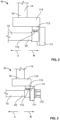
Fig. 2 is partial side view of a second exemplary Scotch yoke mechanism assembled in accordance with the teachings of the present disclosure and showing the Scotch yoke mechanism in a second position; -
Fig. 3 is a partial side view of the first exemplary Scotch yoke mechanism ofFig. 1 and showing the Scotch yoke mechanism in a second position; -
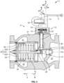
Fig. 4 is a cross-sectional side view of an axial flow slam-shut valve and Scotch yoke mechanism ofFig. 1 assembled in accordance with the teachings of the present disclosure and showing the axial flow slam-shut valve in a closed position and the Scotch yoke mechanism in the first position; -
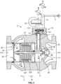
Fig. 5 is a cross-sectional side view of the axial flow slam-shut valve ofFig. 4 in an open position and the Scotch yoke mechanism in the second position; and -
Fig. 6 is side view of a second exemplary actuator assembly for a control valve and including the second exemplary Scotch yoke mechanism ofFig. 2 assembled in accordance with the teachings of the present disclosure and showing the Scotch yoke mechanism in the first position. - An
actuator assembly 1 for an axial flow slam-shut valve is provided with aScotch yoke mechanism 11 to change the direction of movement (or the mode of transmission) to a shut-off control element for the valve. -
Fig. 1 illustrates theactuator assembly 1 for a slam-shut valve and is constructed in accordance with the teachings of the present disclosure. Theactuator assembly 1 includes a first exemplary Scotchyoke mechanism 11, atransmission mechanism 12, afirst transmission shaft 13, and asecond transmission shaft 14. The Scotchyoke mechanism 11 is connected to avalve stem 15 of an axial flow slam-shut valve (as shown inFigs. 4 and5 ) and transmits rotational motion of theactuator assembly 1 to linear motion of thevalve stem 15 to open and close the valve. The Scotchyoke mechanism 11 ofFig. 1 includes aplate 111, abolt 112, abushing 113, and ahandle 114, and will be described in more detail below. As used herein, a Scotch yoke mechanism is a mechanism that includes a pin that couples a sliding component to a rotating component. - The
transmission mechanism 12 includes afirst gear 121 and asecond gear 122 engaged with thefirst gear 121. A radius R1 of thefirst gear 121 is smaller than a radius R2 of thesecond gear 122. Afirst end 16 of thefirst transmission shaft 13 is operatively coupled to theScotch yoke mechanism 11, and an oppositesecond end 17 of thefirst transmission shaft 13 is operatively coupled to thesecond gear 122 of thetransmission mechanism 12. Afirst end 18 of thesecond transmission shaft 14 is operatively coupled to thefirst gear 121, and an oppositesecond end 19 of thesecond transmission shaft 14 is operatively coupled to ahandle 3 of theactuator assembly 1. - In the illustrated example, the radius R1 of the
first gear 121 is smaller than the radius R2 of thesecond gear 122 to achieve a certain movement of thevalve stem 15 when a particular torque is applied to thehandle 3 of theactuator assembly 1. However, the torque required to move thevalve stem 15 can be changed by altering the ratio of the radius R1 of thefirst gear 121 to the radius R2 of thesecond gear 122. As such, the torque to operate theactuator assembly 1 can be increased by changing the gear radius ratio of thetransmission mechanism 12 to a torque required for opening the actuator assembly 1 (i.e., moving the valve stem 15). In another example, the radius R1 of thefirst gear 121 is larger than the radius R2 of thesecond gear 122. - In applications where a large torque is required to move the
valve stem 15 along a C axis, theScotch yoke mechanism 11 and thetransmission mechanism 12 cooperate with each other to increase the torque achieved by rotating thehandle 3, accordingly. In one example, thefirst gear 121 comprises a gear set (e.g., two or more planetary gears), and the output radius of the gear set 121 is less than the radius R2 of thesecond gear 122. A suitable number of gears for the gear set 121 and a suitable size of the gear set may be selected by a skilled person in the art according to a specific application environment and to achieve the purpose of amplifying the torque by changing a radius ratio R1 :R2 of thegears - In the illustrated example, the
first transmission shaft 13 and asecond transmission shaft 14 are arranged so that the axis of thesecond gear 122 is aligned with the axis of thefirst transmission shaft 13. - When the
transmission mechanism 12 is activated, thefirst gear 121 is rotatably driven by an external force (i.e., thehandle 3 rotates to move the second transmission shaft 14), thesecond gear 122 is rotated to rotate thefirst transmission shaft 13, and theScotch yoke mechanism 11, which is operatively coupled to thefirst transmission shaft 13, converts the rotary motion provided by thesecond gear 122 to a linear motion to move thevalve stem 15, as will be described further below. Specifically, thehandle 3 is rotated about a longitudinal axis A of thesecond transmission shaft 14 to rotate thefirst gear 121 about the longitudinal axis A. The rotational motion of thefirst gear 121 drives thesecond gear 122 and thefirst transmission shaft 13 to rotate about a longitudinal axis B of thefirst transmission shaft 13 in a direction opposite that of thefirst gear 121. The rotational motion of thesecond gear 122 and thefirst transmission shaft 13 is transmitted to theScotch yoke mechanism 11. - The
first transmission shaft 13 includes afirst transmission portion 131 and asecond transmission portion 132 that are axially aligned about the B axis. Thesecond transmission portion 132 is operatively coupled to thehandle 114 of theScotch yoke mechanism 11, and thefirst transmission portion 131 is connected to thesecond gear 122 of thetransmission mechanism 12. As will be described further below, thefirst transmission portion 131 may be operatively coupled to a trigger mechanism for a slam-shut functionality. Thefirst transmission portion 131 may be integrally formed with thesecond transmission portion 132. However, in another example, thefirst transmission portion 131 and thesecond transmission portion 132 are two separate components connected to each other by a suitable fastening means such that thefirst transmission portion 131 and thesecond transmission portion 132 move together as a unitary component. The structure of thetransmission shaft 13 may be determined according to specific application requirements. - To operate the
actuator assembly 1, thehandle 3 is rotated in a Q direction about the longitudinal axis A of thesecond transmission shaft 14 to rotate thesecond transmission shaft 14 and thefirst gear 121 in the Q direction about the longitudinal axis A. The rotational motion of thefirst gear 121 is transmitted to thesecond gear 122, causing thesecond gear 122 to rotate in an S direction, opposite the Q direction, about the longitudinal axis B of thefirst transmission shaft 13. Thesecond gear 122 rotates thefirst transmission shaft 13 in the S direction, which in turn transmits the rotational motion about the longitudinal axis B to theScotch yoke mechanism 11. TheScotch yoke mechanism 11 converts rotational motion transmitted from thefirst transmission shaft 13 to linear motion along the longitudinal axis C of thevalve stem 15. In this example, a rotational motion S of thefirst shaft 13 causes thevalve stem 15 to move linearly in the direction K, and a rotational motion T of thefirst shaft 13 causes thevalve stem 15 to move linearly in the direction J. As shown inFig. 1 , thevalve stem 15 is in a first position. - In the first exemplary
Scotch yoke mechanism 11 ofFigs. 1 and3 , theplate 111 is arranged on afirst end 20 of thevalve stem 15, thebolt 112 is mounted to thehandle 114, and thehandle 114 is connected to thesecond end 16 of thefirst transmission shaft 13. Thebushing 113 is movably arranged on thebolt 112, and thebushing 113 is operatively coupled to the side surface of theplate 111. In the first exemplaryScotch yoke mechanism 11, theplate 111 is a separate part arranged at thefirst end 20 of thevalve stem 15 and is secured to theplate 111 via thebushing 113. In some cases, theplate 111 is additionally secured to thevalve stem 15 via afastening member 115 As shown inFig. 3 , thevalve stem 15 is in a second position. - When the
first transmission shaft 13 drives thehandle 114 to rotate, the bushing 113 (arranged on the bolt 112) will drive theplate 111 linearly, thereby causing theplate 111 to move thevalve stem 15 in the J or K directions. - In
Fig. 2 , a second exemplaryScotch yoke mechanism 11 is constructed according to the teachings of the present disclosure. In this example, theplate 111 is integrally formed with thevalve stem 15 to facilitate installation and to reduce costs associated with assembly and manufacturing. - Turning to
Figs. 4 and5 , an exemplaryfluid control device 2 is constructed according to the teachings of the present disclosure. Thefluid control device 2 is an axial flow slam-shutvalve 2 and is operatively coupled to anactuator assembly 1, such as theactuator assembly 1 ofFigs. 1 and3 . The axial flow slam-shutvalve 2 includes avalve body 21 and avalve assembly 22 arranged in thevalve body 21. Thevalve body 21 includes aninlet 25, anoutlet 26, and afluid flow path 27 between theinlet 25 and theoutlet 26. Thevalve body 21 includes a longitudinal axis that is coaxially aligned with the longitudinal axis C of thevalve stem 15. Theflow path 27 is arranged outside thevalve assembly 22 so that theflow path 27 is no longer limited by the size of thevalve assembly 22 and can provide greater flow. - The
valve assembly 22 includes thevalve stem 15, a control element 223 coupled to a second end 31 of thestem 15, aspring 222, and atrigger mechanism 23. Thevalve stem 15 and control element 223 of thevalve assembly 22 are movable along the longitudinal axis C. The control element 223 is biased by thespring 222 toward a closed position in which the control element 223 engages aseat 28 to prevent fluid flow between theinlet 25 and theoutlet 26. In the illustrated example, thevalve assembly 22 is arranged inside avalve cage 24 and theflow path 27 is primarily disposed outside thevalve assembly 22. Thefirst end 20 of thevalve stem 15, opposite the second end 31, is connected to theplate 111 of theactuator assembly 1. The control element 223 moves linearly with thevalve stem 15 in the K direction to open thevalve 2 or in the J direction to engage thevalve seat 28 to close thevalve 2. - The
trigger mechanism 23 is responsive to fluid pressure and is arranged on the outside of thevalve body 21. Thetrigger mechanism 23 is operatively coupled to thefirst transmission portion 131 of thefirst transmission shaft 13 of theactuator assembly 1. Thesecond transmission portion 132 of thefirst transmission shaft 13 is operatively coupled to thevalve stem 15 via theScotch yoke mechanism 11. Thetrigger mechanism 23 is configured to prevent rotation, against the biasing force applied by thespring 222 through theScotch yoke mechanism 11, of thefirst transmission shaft 13 in the rotational direction T in a first mode of operation, and releases thefirst transmission shaft 13 to allow rotation of thefirst transmission shaft 13, under the biasing force applied by thespring 222 through theScotch yoke mechanism 11, in the rotational direction T in a second mode of operation. - As shown in
Figs. 4 and6 , the slam-shutvalve 2 is in a closed position such that the control element 223 engages theseat 28 to close thevalve 2. To open thevalve 2 from this closed position, thehandle 3, which is removable from thesecond transmission shaft 14 and is so removed during normal operation of thevalve 2, may be connected to thesecond transmission shaft 14 and rotated in a first direction Q about the longitudinal axis A of thesecond transmission shaft 14. Thesecond transmission shaft 14 of thetransmission mechanism 12 causes thefirst transmission shaft 13 to rotate in a rotational direction S (via first andsecond gears 121, 122). Rotational motion of thefirst transmission shaft 13 in the rotational direction S is converted to linear motion by theScotch yoke mechanism 11, thereby moving thevalve stem 15 and the control element 223 in a translational direction K along the longitudinal axis C. As such, the control element 223 moves away from thevalve seat 28, opening thevalve 2, as shown inFig. 5 . Thevalve 2 is maintained in this open position by thetrigger mechanism 23, which prevents rotation of thefirst transmission shaft 13 when no over-pressure or under-pressure condition for which thetrigger mechanism 23 has been configured is present (i.e., in a first, normal mode of operation). A relatively small torque applied via thehandle 3 is multiplied via the gear ratio between the first andsecond gears valve 2 much less cumbersome than in known slam-shut valves. - In
Fig. 5 , the axial flow slam-shutvalve 2 is in an open position. When thevalve 2 is open, fluid can flow through the openings in thecage 24 and into theflow pathway 27, and thevalve 2 will be maintained in this open position absent any over-pressure or under-pressure condition for which thetrigger mechanism 23 has been configured. When an over-pressure or under-pressure condition is detected by thetrigger mechanism 23, thetrigger mechanism 23 facilitates theshaft 13 to rotate in the rotational direction T. By facilitating theshaft 13 to rotate, thetrigger mechanism 23 thus enables theshaft 15 and thecontrol element 221 to move in the direction J under the biasing force provided by thespring 222 until thecontrol element 221 engages theseat 28. In this closed position, fluid is prevented from flowing between theinlet 25 and theoutlet 26. When the over-pressure or under-pressure condition is cleared, thevalve 2 can be reset (i.e., opened) via thehandle 3 as described above. - According to the invention, the
actuator assembly 1 is disposed outside of thevalve body 21 of theaxial valve 2. As such, the range of the shut-off point of the axial flow slam-shutvalve 2 is not limited by the range of theScotch yoke mechanism 11. When the torque requirement for actuating thevalve assembly 22 is greater, the size of theScotch yoke mechanism 11 may remain the same, and thetransmission mechanism 12 may be modified to satisfy the torque requirement (e.g., the gear ratio betweengears transmission mechanism 12 may be easily modified without replacing thehandle 3 with a longer handle or requiring an increase in the manual force applied to thehandle 3. As such, all modifications may take place outside of thevalve body 21, and do not require disassembling theaxial flow valve 2. - In the present disclosure, the
actuator assembly 1, thetransmission mechanism 12, andScotch yoke mechanism 11 adopt a modular design, which is easy to install and maintain. Standardized, generalized or serialized components can be used in thetransmission mechanism 12 andScotch yoke mechanism 11, which are easy to produce with a lower cost. - The figures and description provided herein depict and describe preferred embodiments of an axial regulator for purposes of illustration only. One skilled in the art will readily recognize from the foregoing discussion that alternative embodiments of the components illustrated herein may be employed without departing from the principles of the invention which are defined by the appended claims. Thus, upon reading this disclosure, those of skill in the art will appreciate still additional alternative structural and functional designs for the axial regulator. Thus, while particular embodiments and applications have been illustrated and described, it is to be understood that the disclosed embodiments are not limited to the precise construction and components disclosed herein. Various modifications, changes and variations, which will be apparent to those skilled in the art, may be made in the arrangement, operation and details of the methods and components disclosed herein without departing from the scope defined in the appended claims.
Claims (14)
- An axial flow slam-shut valve (2), comprising:a valve body (21);a valve assembly (22) arranged in the valve body and having a stem (15), a control element (223) that is coupled to the stem (15), and a spring (222);the valve body having an inlet (25), an outlet (26), and a fluid flow path (27) that is between the inlet and the outlet and is positioned outside of the valve assembly;a seat (28), wherein the control element and the stem are movable along a longitudinal axis (C) and biased by the spring (222) toward a closed position, in which the control element engages the seat;an actuator assembly (1) disposed outside of the valve body and including a first transmission shaft (13) that is operatively coupled to the stem via a Scotch yoke mechanism (11); anda trigger mechanism (23) that is responsive to fluid pressure,wherein rotational motion of the first transmission shaft in a first rotational direction (S) causes movement of the stem and the control element in a first translational direction (K) to separate the control element from the seat; andwherein the trigger mechanism prevents rotation of the first transmission shaft in a second rotational direction (T) in a first mode of operation and releases the first transmission shaft to allow rotation of the first transmission shaft in the second rotational direction in a second mode of operation,characterized in thatthe actuator assembly further comprises a second transmission shaft (14) and a transmission mechanism (12).
- The axial flow slam-shut valve (2) of claim 1, wherein the first transmission shaft (13) is operatively coupled to the stem (15) via the Scotch yoke mechanism such that the rotational motion of the first transmission shaft in the first rotational direction (S) causes movement of the stem and the control element (223) along the longitudinal axis (C) in the first translational direction (K).
- The axial flow slam-shut valve (2) of claim 2, wherein the actuator assembly (1) further comprises a handle (3) that is positioned outside of the valve body (21), and wherein the handle is operatively coupleable to the first transmission shaft (13) and is configured to facilitate rotation of the first transmission shaft in the first rotational direction (S) to move the control element (223) along the longitudinal axis (C) in the first translational direction (K) from the closed position to an open position, in which the control element is separated from the seat (28).
- The axial flow slam-shut valve (2) of claim 2, wherein the longitudinal axis (C) is the longitudinal axis of the valve body (21) , wherein said longitudinal axis (C) extends between the inlet (25) and the outlet (26) of the body
- The axial flow slam-shut valve (2) of claim 2, wherein the first transmission shaft (13) is operatively coupled to a first gear (121).
- The axial flow slam-shut valve (2) of claim 5, wherein a handle (3) is operatively coupleable, via the second transmission shaft (14), to a second gear (122) that is engaged with the first gear (121).
- The axial flow slam-shut valve (2) of claim 6, wherein the second gear (122) is smaller than the first gear (121).
- The axial flow slam-shut valve (2) of claim 1, wherein the actuator assembly (1) further comprises a handle (3) that is positioned outside of the valve body (21), and wherein the handle is operatively coupleable to the first transmission shaft (13) and is configured to facilitate rotation of the first transmission shaft in the first rotational direction (S) to move the control element (223) in the first translational direction (K) from the closed position to an open position in which the control element is separated from the seat (28).
- The axial flow slam-shut valve (2) of claim 8, wherein the first transmission shaft (13) is operatively coupled to a first gear (121).
- The axial flow slam-shut valve (2) of claim 9, wherein the handle (3) is operatively coupleable to a second gear (122) that is engaged with the first gear (121).
- The axial flow slam-shut valve (2) of claim 10, wherein the second gear (122) is smaller than the first gear.
- The axial flow slam-shut valve (2) of claim 1, wherein the Scotch yoke mechanism includes a plate (111), a bolt (112), a bushing (113), and a Scotch yoke handle (114)
- The axial flow slam-shut valve (2) of claim 12, wherein the plate (111) is arranged on a first end (20) of the stem (15), the bolt (112) is mounted to the Scotch yoke handle (114), and the Scotch yoke handle is connected to an end (16) of the first transmission shaft (13), wherein the bushing (113) is movably arranged on the bolt, and wherein the bushing is operatively coupled to a side surface of the plate.
- The axial flow slam shut valve of claim 1, wherein the transmission mechanism (12) includes a first gear (121) and a second gear (122) engaged with the first gear.
Applications Claiming Priority (2)
| Application Number | Priority Date | Filing Date | Title |
|---|---|---|---|
| CN201820263324 | 2018-02-10 | ||
| PCT/CN2019/074750 WO2019154404A1 (en) | 2018-02-10 | 2019-02-10 | An actuator assembly for a fluid control device |
Publications (3)
| Publication Number | Publication Date |
|---|---|
| EP3749884A1 EP3749884A1 (en) | 2020-12-16 |
| EP3749884A4 EP3749884A4 (en) | 2021-11-03 |
| EP3749884B1 true EP3749884B1 (en) | 2023-09-06 |
Family
ID=67548761
Family Applications (1)
| Application Number | Title | Priority Date | Filing Date |
|---|---|---|---|
| EP19750559.7A Active EP3749884B1 (en) | 2018-02-10 | 2019-02-10 | Axial flow slam-shut valve |
Country Status (3)
| Country | Link |
|---|---|
| US (1) | US11692640B2 (en) |
| EP (1) | EP3749884B1 (en) |
| WO (1) | WO2019154404A1 (en) |
Families Citing this family (5)
| Publication number | Priority date | Publication date | Assignee | Title |
|---|---|---|---|---|
| US11326713B2 (en) * | 2019-06-28 | 2022-05-10 | Fisher Jeon Gas Equipment (Chengdu) Co., Ltd. | Actuator assembly for a fluid control device |
| CN112539290B (en) * | 2019-09-23 | 2025-05-16 | 费希尔久安输配设备(成都)有限公司 | Mechanical stop bleed for fluid control equipment |
| US11920688B2 (en) | 2019-09-25 | 2024-03-05 | Fisher Jeon Gas Equipment (Chengdu) Co., Ltd. | Modular valve system |
| CN112555481A (en) * | 2019-09-25 | 2021-03-26 | 费希尔久安输配设备(成都)有限公司 | Modular valve system |
| CN113775800B (en) * | 2021-09-30 | 2023-11-28 | 建安消防设备(浙江)有限公司 | Valve body structure for fire control |
Citations (1)
| Publication number | Priority date | Publication date | Assignee | Title |
|---|---|---|---|---|
| US5178185A (en) * | 1991-03-06 | 1993-01-12 | Hydra-Shield Manufacturing Inc. | Suction inlet valve for fire truck pumpers |
Family Cites Families (14)
| Publication number | Priority date | Publication date | Assignee | Title |
|---|---|---|---|---|
| US4457334A (en) | 1982-09-24 | 1984-07-03 | The United States Of America As Represented By The Secretary Of The Navy | Pressure sensitive valve actuator |
| US4580596A (en) * | 1983-01-18 | 1986-04-08 | Stehling Henry J | Check valve with dual locking mechanism |
| US5622201A (en) * | 1996-02-28 | 1997-04-22 | Chang; King | Bucket valve with removable handle |
| US7040339B2 (en) * | 2004-03-31 | 2006-05-09 | Hydra-Shield Manufacturing, Inc. | Suction inlet valve for fire truck pumpers |
| JP2008151293A (en) * | 2006-12-19 | 2008-07-03 | Yamatake Corp | Electric control valve and electric actuator |
| US9745901B2 (en) | 2009-06-17 | 2017-08-29 | Valeo Systemes De Controle Moteur | Valve comprising a movement transformation device |
| CN101696667A (en) * | 2009-10-29 | 2010-04-21 | 奇瑞汽车股份有限公司 | EGR valve of engine |
| JP2012219903A (en) * | 2011-04-07 | 2012-11-12 | Denso Corp | Valve device |
| JP2017057814A (en) * | 2015-09-17 | 2017-03-23 | 大豊工業株式会社 | Actuator valve mechanism |
| GB2542841B (en) * | 2015-10-01 | 2017-10-18 | Goodwin Plc | Valve |
| JP2017155846A (en) * | 2016-03-02 | 2017-09-07 | ミネベアミツミ株式会社 | Rotor, cylindrical cam mechanism, and valve unit |
| US10473232B2 (en) * | 2017-01-13 | 2019-11-12 | Borgwarner Inc. | Split linkage mechanism for valve assembly |
| RO134311A2 (en) | 2018-10-10 | 2020-07-30 | Emerson Process Management Regulator Technologies Inc. | Slam shut-off safety assembly for providing redundant safety switch-off |
| US11326713B2 (en) * | 2019-06-28 | 2022-05-10 | Fisher Jeon Gas Equipment (Chengdu) Co., Ltd. | Actuator assembly for a fluid control device |
-
2019
- 2019-02-10 EP EP19750559.7A patent/EP3749884B1/en active Active
- 2019-02-10 US US16/968,864 patent/US11692640B2/en active Active
- 2019-02-10 WO PCT/CN2019/074750 patent/WO2019154404A1/en not_active Ceased
Patent Citations (1)
| Publication number | Priority date | Publication date | Assignee | Title |
|---|---|---|---|---|
| US5178185A (en) * | 1991-03-06 | 1993-01-12 | Hydra-Shield Manufacturing Inc. | Suction inlet valve for fire truck pumpers |
Also Published As
| Publication number | Publication date |
|---|---|
| US20210048119A1 (en) | 2021-02-18 |
| WO2019154404A1 (en) | 2019-08-15 |
| US11692640B2 (en) | 2023-07-04 |
| EP3749884A4 (en) | 2021-11-03 |
| EP3749884A1 (en) | 2020-12-16 |
Similar Documents
| Publication | Publication Date | Title |
|---|---|---|
| US11692640B2 (en) | Actuator assembly for a fluid control device | |
| US20140346380A1 (en) | Electrically Operated Valve Assembly | |
| EP2394082B1 (en) | Manual override apparatus for linear actuators | |
| CN102369376B (en) | Pressure independent control valve | |
| EP2499410B1 (en) | Coupling apparatus for use with electric actuators | |
| JP5322953B2 (en) | Throttle valve | |
| JP5744896B2 (en) | Electric actuator with internal load device | |
| US20080217569A1 (en) | Low Torque Gate Valve Mechanism | |
| US9714722B2 (en) | Pilot valve and/or proportional valve | |
| EP2215390B1 (en) | Rotary valve lever apparatus having interchangeable shaft adaptor inserts | |
| US7334773B2 (en) | Outflow valve having a cable operated closure mechanism | |
| US11326713B2 (en) | Actuator assembly for a fluid control device | |
| WO2024223664A1 (en) | A valve arrangement with improved balancing functionality | |
| CN212107065U (en) | Manual actuating assembly, actuator assembly and fluid control equipment | |
| CN211117837U (en) | Fluid Control Equipment and Emergency Shutoff Valves | |
| CN112145761B (en) | Manual actuator assemblies for fluid control equipment and fluid control equipment having the same. | |
| IL284806A (en) | Safety valve | |
| EP2320166B1 (en) | Expansion valve | |
| CN112539290B (en) | Mechanical stop bleed for fluid control equipment | |
| EP1850042A3 (en) | Angled poppet valve manual override mechanism | |
| RU109811U1 (en) | PNEUMATIC DRIVE | |
| CN114635972A (en) | Stop valve structure and tap |
Legal Events
| Date | Code | Title | Description |
|---|---|---|---|
| STAA | Information on the status of an ep patent application or granted ep patent |
Free format text: STATUS: THE INTERNATIONAL PUBLICATION HAS BEEN MADE |
|
| PUAI | Public reference made under article 153(3) epc to a published international application that has entered the european phase |
Free format text: ORIGINAL CODE: 0009012 |
|
| STAA | Information on the status of an ep patent application or granted ep patent |
Free format text: STATUS: REQUEST FOR EXAMINATION WAS MADE |
|
| 17P | Request for examination filed |
Effective date: 20200831 |
|
| AK | Designated contracting states |
Kind code of ref document: A1 Designated state(s): AL AT BE BG CH CY CZ DE DK EE ES FI FR GB GR HR HU IE IS IT LI LT LU LV MC MK MT NL NO PL PT RO RS SE SI SK SM TR |
|
| AX | Request for extension of the european patent |
Extension state: BA ME |
|
| DAV | Request for validation of the european patent (deleted) | ||
| DAX | Request for extension of the european patent (deleted) | ||
| A4 | Supplementary search report drawn up and despatched |
Effective date: 20211006 |
|
| RIC1 | Information provided on ipc code assigned before grant |
Ipc: F16K 1/12 20060101ALI20210930BHEP Ipc: F16K 17/168 20060101ALI20210930BHEP Ipc: F16K 31/56 20060101ALI20210930BHEP Ipc: F16K 17/00 20060101ALI20210930BHEP Ipc: F16K 3/24 20060101ALI20210930BHEP Ipc: F16K 31/528 20060101ALI20210930BHEP Ipc: F16K 31/60 20060101ALI20210930BHEP Ipc: F16K 31/53 20060101AFI20210930BHEP |
|
| STAA | Information on the status of an ep patent application or granted ep patent |
Free format text: STATUS: EXAMINATION IS IN PROGRESS |
|
| 17Q | First examination report despatched |
Effective date: 20220906 |
|
| GRAP | Despatch of communication of intention to grant a patent |
Free format text: ORIGINAL CODE: EPIDOSNIGR1 |
|
| STAA | Information on the status of an ep patent application or granted ep patent |
Free format text: STATUS: GRANT OF PATENT IS INTENDED |
|
| INTG | Intention to grant announced |
Effective date: 20230406 |
|
| GRAS | Grant fee paid |
Free format text: ORIGINAL CODE: EPIDOSNIGR3 |
|
| GRAA | (expected) grant |
Free format text: ORIGINAL CODE: 0009210 |
|
| STAA | Information on the status of an ep patent application or granted ep patent |
Free format text: STATUS: THE PATENT HAS BEEN GRANTED |
|
| AK | Designated contracting states |
Kind code of ref document: B1 Designated state(s): AL AT BE BG CH CY CZ DE DK EE ES FI FR GB GR HR HU IE IS IT LI LT LU LV MC MK MT NL NO PL PT RO RS SE SI SK SM TR |
|
| P01 | Opt-out of the competence of the unified patent court (upc) registered |
Effective date: 20230802 |
|
| REG | Reference to a national code |
Ref country code: GB Ref legal event code: FG4D |
|
| REG | Reference to a national code |
Ref country code: CH Ref legal event code: EP |
|
| REG | Reference to a national code |
Ref country code: DE Ref legal event code: R096 Ref document number: 602019036838 Country of ref document: DE |
|
| REG | Reference to a national code |
Ref country code: IE Ref legal event code: FG4D |
|
| REG | Reference to a national code |
Ref country code: LT Ref legal event code: MG9D |
|
| REG | Reference to a national code |
Ref country code: NL Ref legal event code: MP Effective date: 20230906 |
|
| PG25 | Lapsed in a contracting state [announced via postgrant information from national office to epo] |
Ref country code: GR Free format text: LAPSE BECAUSE OF FAILURE TO SUBMIT A TRANSLATION OF THE DESCRIPTION OR TO PAY THE FEE WITHIN THE PRESCRIBED TIME-LIMIT Effective date: 20231207 |
|
| PG25 | Lapsed in a contracting state [announced via postgrant information from national office to epo] |
Ref country code: SE Free format text: LAPSE BECAUSE OF FAILURE TO SUBMIT A TRANSLATION OF THE DESCRIPTION OR TO PAY THE FEE WITHIN THE PRESCRIBED TIME-LIMIT Effective date: 20230906 Ref country code: RS Free format text: LAPSE BECAUSE OF FAILURE TO SUBMIT A TRANSLATION OF THE DESCRIPTION OR TO PAY THE FEE WITHIN THE PRESCRIBED TIME-LIMIT Effective date: 20230906 Ref country code: NO Free format text: LAPSE BECAUSE OF FAILURE TO SUBMIT A TRANSLATION OF THE DESCRIPTION OR TO PAY THE FEE WITHIN THE PRESCRIBED TIME-LIMIT Effective date: 20231206 Ref country code: LV Free format text: LAPSE BECAUSE OF FAILURE TO SUBMIT A TRANSLATION OF THE DESCRIPTION OR TO PAY THE FEE WITHIN THE PRESCRIBED TIME-LIMIT Effective date: 20230906 Ref country code: LT Free format text: LAPSE BECAUSE OF FAILURE TO SUBMIT A TRANSLATION OF THE DESCRIPTION OR TO PAY THE FEE WITHIN THE PRESCRIBED TIME-LIMIT Effective date: 20230906 Ref country code: HR Free format text: LAPSE BECAUSE OF FAILURE TO SUBMIT A TRANSLATION OF THE DESCRIPTION OR TO PAY THE FEE WITHIN THE PRESCRIBED TIME-LIMIT Effective date: 20230906 Ref country code: GR Free format text: LAPSE BECAUSE OF FAILURE TO SUBMIT A TRANSLATION OF THE DESCRIPTION OR TO PAY THE FEE WITHIN THE PRESCRIBED TIME-LIMIT Effective date: 20231207 Ref country code: FI Free format text: LAPSE BECAUSE OF FAILURE TO SUBMIT A TRANSLATION OF THE DESCRIPTION OR TO PAY THE FEE WITHIN THE PRESCRIBED TIME-LIMIT Effective date: 20230906 |
|
| REG | Reference to a national code |
Ref country code: AT Ref legal event code: MK05 Ref document number: 1608950 Country of ref document: AT Kind code of ref document: T Effective date: 20230906 |
|
| PG25 | Lapsed in a contracting state [announced via postgrant information from national office to epo] |
Ref country code: NL Free format text: LAPSE BECAUSE OF FAILURE TO SUBMIT A TRANSLATION OF THE DESCRIPTION OR TO PAY THE FEE WITHIN THE PRESCRIBED TIME-LIMIT Effective date: 20230906 |
|
| PG25 | Lapsed in a contracting state [announced via postgrant information from national office to epo] |
Ref country code: IS Free format text: LAPSE BECAUSE OF FAILURE TO SUBMIT A TRANSLATION OF THE DESCRIPTION OR TO PAY THE FEE WITHIN THE PRESCRIBED TIME-LIMIT Effective date: 20240106 |
|
| PG25 | Lapsed in a contracting state [announced via postgrant information from national office to epo] |
Ref country code: AT Free format text: LAPSE BECAUSE OF FAILURE TO SUBMIT A TRANSLATION OF THE DESCRIPTION OR TO PAY THE FEE WITHIN THE PRESCRIBED TIME-LIMIT Effective date: 20230906 |
|
| PG25 | Lapsed in a contracting state [announced via postgrant information from national office to epo] |
Ref country code: ES Free format text: LAPSE BECAUSE OF FAILURE TO SUBMIT A TRANSLATION OF THE DESCRIPTION OR TO PAY THE FEE WITHIN THE PRESCRIBED TIME-LIMIT Effective date: 20230906 |
|
| PG25 | Lapsed in a contracting state [announced via postgrant information from national office to epo] |
Ref country code: SM Free format text: LAPSE BECAUSE OF FAILURE TO SUBMIT A TRANSLATION OF THE DESCRIPTION OR TO PAY THE FEE WITHIN THE PRESCRIBED TIME-LIMIT Effective date: 20230906 Ref country code: RO Free format text: LAPSE BECAUSE OF FAILURE TO SUBMIT A TRANSLATION OF THE DESCRIPTION OR TO PAY THE FEE WITHIN THE PRESCRIBED TIME-LIMIT Effective date: 20230906 Ref country code: IS Free format text: LAPSE BECAUSE OF FAILURE TO SUBMIT A TRANSLATION OF THE DESCRIPTION OR TO PAY THE FEE WITHIN THE PRESCRIBED TIME-LIMIT Effective date: 20240106 Ref country code: ES Free format text: LAPSE BECAUSE OF FAILURE TO SUBMIT A TRANSLATION OF THE DESCRIPTION OR TO PAY THE FEE WITHIN THE PRESCRIBED TIME-LIMIT Effective date: 20230906 Ref country code: EE Free format text: LAPSE BECAUSE OF FAILURE TO SUBMIT A TRANSLATION OF THE DESCRIPTION OR TO PAY THE FEE WITHIN THE PRESCRIBED TIME-LIMIT Effective date: 20230906 Ref country code: CZ Free format text: LAPSE BECAUSE OF FAILURE TO SUBMIT A TRANSLATION OF THE DESCRIPTION OR TO PAY THE FEE WITHIN THE PRESCRIBED TIME-LIMIT Effective date: 20230906 Ref country code: AT Free format text: LAPSE BECAUSE OF FAILURE TO SUBMIT A TRANSLATION OF THE DESCRIPTION OR TO PAY THE FEE WITHIN THE PRESCRIBED TIME-LIMIT Effective date: 20230906 Ref country code: SK Free format text: LAPSE BECAUSE OF FAILURE TO SUBMIT A TRANSLATION OF THE DESCRIPTION OR TO PAY THE FEE WITHIN THE PRESCRIBED TIME-LIMIT Effective date: 20230906 Ref country code: PT Free format text: LAPSE BECAUSE OF FAILURE TO SUBMIT A TRANSLATION OF THE DESCRIPTION OR TO PAY THE FEE WITHIN THE PRESCRIBED TIME-LIMIT Effective date: 20240108 |
|
| PG25 | Lapsed in a contracting state [announced via postgrant information from national office to epo] |
Ref country code: PL Free format text: LAPSE BECAUSE OF FAILURE TO SUBMIT A TRANSLATION OF THE DESCRIPTION OR TO PAY THE FEE WITHIN THE PRESCRIBED TIME-LIMIT Effective date: 20230906 |
|
| REG | Reference to a national code |
Ref country code: DE Ref legal event code: R097 Ref document number: 602019036838 Country of ref document: DE |
|
| PG25 | Lapsed in a contracting state [announced via postgrant information from national office to epo] |
Ref country code: DK Free format text: LAPSE BECAUSE OF FAILURE TO SUBMIT A TRANSLATION OF THE DESCRIPTION OR TO PAY THE FEE WITHIN THE PRESCRIBED TIME-LIMIT Effective date: 20230906 |
|
| PLBE | No opposition filed within time limit |
Free format text: ORIGINAL CODE: 0009261 |
|
| STAA | Information on the status of an ep patent application or granted ep patent |
Free format text: STATUS: NO OPPOSITION FILED WITHIN TIME LIMIT |
|
| PG25 | Lapsed in a contracting state [announced via postgrant information from national office to epo] |
Ref country code: DK Free format text: LAPSE BECAUSE OF FAILURE TO SUBMIT A TRANSLATION OF THE DESCRIPTION OR TO PAY THE FEE WITHIN THE PRESCRIBED TIME-LIMIT Effective date: 20230906 Ref country code: SI Free format text: LAPSE BECAUSE OF FAILURE TO SUBMIT A TRANSLATION OF THE DESCRIPTION OR TO PAY THE FEE WITHIN THE PRESCRIBED TIME-LIMIT Effective date: 20230906 |
|
| 26N | No opposition filed |
Effective date: 20240607 |
|
| REG | Reference to a national code |
Ref country code: DE Ref legal event code: R119 Ref document number: 602019036838 Country of ref document: DE |
|
| PG25 | Lapsed in a contracting state [announced via postgrant information from national office to epo] |
Ref country code: MC Free format text: LAPSE BECAUSE OF FAILURE TO SUBMIT A TRANSLATION OF THE DESCRIPTION OR TO PAY THE FEE WITHIN THE PRESCRIBED TIME-LIMIT Effective date: 20230906 |
|
| REG | Reference to a national code |
Ref country code: CH Ref legal event code: PL |
|
| PG25 | Lapsed in a contracting state [announced via postgrant information from national office to epo] |
Ref country code: LU Free format text: LAPSE BECAUSE OF NON-PAYMENT OF DUE FEES Effective date: 20240210 |
|
| PG25 | Lapsed in a contracting state [announced via postgrant information from national office to epo] |
Ref country code: CH Free format text: LAPSE BECAUSE OF NON-PAYMENT OF DUE FEES Effective date: 20240229 |
|
| GBPC | Gb: european patent ceased through non-payment of renewal fee |
Effective date: 20240210 |
|
| PG25 | Lapsed in a contracting state [announced via postgrant information from national office to epo] |
Ref country code: LU Free format text: LAPSE BECAUSE OF NON-PAYMENT OF DUE FEES Effective date: 20240210 Ref country code: CH Free format text: LAPSE BECAUSE OF NON-PAYMENT OF DUE FEES Effective date: 20240229 |
|
| PG25 | Lapsed in a contracting state [announced via postgrant information from national office to epo] |
Ref country code: BG Free format text: LAPSE BECAUSE OF FAILURE TO SUBMIT A TRANSLATION OF THE DESCRIPTION OR TO PAY THE FEE WITHIN THE PRESCRIBED TIME-LIMIT Effective date: 20230906 |
|
| PG25 | Lapsed in a contracting state [announced via postgrant information from national office to epo] |
Ref country code: BG Free format text: LAPSE BECAUSE OF FAILURE TO SUBMIT A TRANSLATION OF THE DESCRIPTION OR TO PAY THE FEE WITHIN THE PRESCRIBED TIME-LIMIT Effective date: 20230906 |
|
| REG | Reference to a national code |
Ref country code: BE Ref legal event code: MM Effective date: 20240229 |
|
| PG25 | Lapsed in a contracting state [announced via postgrant information from national office to epo] |
Ref country code: DE Free format text: LAPSE BECAUSE OF NON-PAYMENT OF DUE FEES Effective date: 20240903 |
|
| PG25 | Lapsed in a contracting state [announced via postgrant information from national office to epo] |
Ref country code: BE Free format text: LAPSE BECAUSE OF NON-PAYMENT OF DUE FEES Effective date: 20240229 |
|
| PG25 | Lapsed in a contracting state [announced via postgrant information from national office to epo] |
Ref country code: GB Free format text: LAPSE BECAUSE OF NON-PAYMENT OF DUE FEES Effective date: 20240210 |
|
| PG25 | Lapsed in a contracting state [announced via postgrant information from national office to epo] |
Ref country code: IE Free format text: LAPSE BECAUSE OF NON-PAYMENT OF DUE FEES Effective date: 20240210 |
|
| PG25 | Lapsed in a contracting state [announced via postgrant information from national office to epo] |
Ref country code: IE Free format text: LAPSE BECAUSE OF NON-PAYMENT OF DUE FEES Effective date: 20240210 Ref country code: GB Free format text: LAPSE BECAUSE OF NON-PAYMENT OF DUE FEES Effective date: 20240210 Ref country code: DE Free format text: LAPSE BECAUSE OF NON-PAYMENT OF DUE FEES Effective date: 20240903 Ref country code: BE Free format text: LAPSE BECAUSE OF NON-PAYMENT OF DUE FEES Effective date: 20240229 |
|
| PG25 | Lapsed in a contracting state [announced via postgrant information from national office to epo] |
Ref country code: CY Free format text: LAPSE BECAUSE OF FAILURE TO SUBMIT A TRANSLATION OF THE DESCRIPTION OR TO PAY THE FEE WITHIN THE PRESCRIBED TIME-LIMIT; INVALID AB INITIO Effective date: 20190210 |
|
| PG25 | Lapsed in a contracting state [announced via postgrant information from national office to epo] |
Ref country code: HU Free format text: LAPSE BECAUSE OF FAILURE TO SUBMIT A TRANSLATION OF THE DESCRIPTION OR TO PAY THE FEE WITHIN THE PRESCRIBED TIME-LIMIT; INVALID AB INITIO Effective date: 20190210 |
|
| PG25 | Lapsed in a contracting state [announced via postgrant information from national office to epo] |
Ref country code: TR Free format text: LAPSE BECAUSE OF FAILURE TO SUBMIT A TRANSLATION OF THE DESCRIPTION OR TO PAY THE FEE WITHIN THE PRESCRIBED TIME-LIMIT Effective date: 20230906 |
|
| PGFP | Annual fee paid to national office [announced via postgrant information from national office to epo] |
Ref country code: IT Payment date: 20260121 Year of fee payment: 8 |
|
| PGFP | Annual fee paid to national office [announced via postgrant information from national office to epo] |
Ref country code: FR Payment date: 20260121 Year of fee payment: 8 |