EP3749866B1 - Self-drilling wall plug - Google Patents
Self-drilling wall plug Download PDFInfo
- Publication number
- EP3749866B1 EP3749866B1 EP18705113.1A EP18705113A EP3749866B1 EP 3749866 B1 EP3749866 B1 EP 3749866B1 EP 18705113 A EP18705113 A EP 18705113A EP 3749866 B1 EP3749866 B1 EP 3749866B1
- Authority
- EP
- European Patent Office
- Prior art keywords
- wall
- plug
- wall plug
- cup
- rotational axis
- Prior art date
- Legal status (The legal status is an assumption and is not a legal conclusion. Google has not performed a legal analysis and makes no representation as to the accuracy of the status listed.)
- Active
Links
- 238000005553 drilling Methods 0.000 title claims description 21
- 238000005520 cutting process Methods 0.000 claims description 46
- 230000000149 penetrating effect Effects 0.000 claims description 18
- 230000036346 tooth eruption Effects 0.000 claims description 14
- 239000004566 building material Substances 0.000 claims description 6
- 238000004873 anchoring Methods 0.000 claims description 4
- 239000011505 plaster Substances 0.000 claims description 4
- 238000003801 milling Methods 0.000 claims description 3
- 239000000428 dust Substances 0.000 description 2
- 229910052602 gypsum Inorganic materials 0.000 description 1
- 239000010440 gypsum Substances 0.000 description 1
- 238000003780 insertion Methods 0.000 description 1
- 230000037431 insertion Effects 0.000 description 1
- 238000005259 measurement Methods 0.000 description 1
Images


Classifications
-
- F—MECHANICAL ENGINEERING; LIGHTING; HEATING; WEAPONS; BLASTING
- F16—ENGINEERING ELEMENTS AND UNITS; GENERAL MEASURES FOR PRODUCING AND MAINTAINING EFFECTIVE FUNCTIONING OF MACHINES OR INSTALLATIONS; THERMAL INSULATION IN GENERAL
- F16B—DEVICES FOR FASTENING OR SECURING CONSTRUCTIONAL ELEMENTS OR MACHINE PARTS TOGETHER, e.g. NAILS, BOLTS, CIRCLIPS, CLAMPS, CLIPS OR WEDGES; JOINTS OR JOINTING
- F16B13/00—Dowels or other devices fastened in walls or the like by inserting them in holes made therein for that purpose
- F16B13/002—Dowels or other devices fastened in walls or the like by inserting them in holes made therein for that purpose self-cutting
-
- F—MECHANICAL ENGINEERING; LIGHTING; HEATING; WEAPONS; BLASTING
- F16—ENGINEERING ELEMENTS AND UNITS; GENERAL MEASURES FOR PRODUCING AND MAINTAINING EFFECTIVE FUNCTIONING OF MACHINES OR INSTALLATIONS; THERMAL INSULATION IN GENERAL
- F16B—DEVICES FOR FASTENING OR SECURING CONSTRUCTIONAL ELEMENTS OR MACHINE PARTS TOGETHER, e.g. NAILS, BOLTS, CIRCLIPS, CLAMPS, CLIPS OR WEDGES; JOINTS OR JOINTING
- F16B13/00—Dowels or other devices fastened in walls or the like by inserting them in holes made therein for that purpose
- F16B13/12—Separate metal or non-separate or non-metal dowel sleeves fastened by inserting the screw, nail or the like
- F16B13/124—Separate metal or non-separate or non-metal dowel sleeves fastened by inserting the screw, nail or the like fastened by inserting a threaded element, e.g. screw or bolt
-
- F—MECHANICAL ENGINEERING; LIGHTING; HEATING; WEAPONS; BLASTING
- F16—ENGINEERING ELEMENTS AND UNITS; GENERAL MEASURES FOR PRODUCING AND MAINTAINING EFFECTIVE FUNCTIONING OF MACHINES OR INSTALLATIONS; THERMAL INSULATION IN GENERAL
- F16B—DEVICES FOR FASTENING OR SECURING CONSTRUCTIONAL ELEMENTS OR MACHINE PARTS TOGETHER, e.g. NAILS, BOLTS, CIRCLIPS, CLAMPS, CLIPS OR WEDGES; JOINTS OR JOINTING
- F16B13/00—Dowels or other devices fastened in walls or the like by inserting them in holes made therein for that purpose
- F16B13/001—Dowels or other devices fastened in walls or the like by inserting them in holes made therein for that purpose with means for preventing rotation of the dowel
-
- F—MECHANICAL ENGINEERING; LIGHTING; HEATING; WEAPONS; BLASTING
- F16—ENGINEERING ELEMENTS AND UNITS; GENERAL MEASURES FOR PRODUCING AND MAINTAINING EFFECTIVE FUNCTIONING OF MACHINES OR INSTALLATIONS; THERMAL INSULATION IN GENERAL
- F16B—DEVICES FOR FASTENING OR SECURING CONSTRUCTIONAL ELEMENTS OR MACHINE PARTS TOGETHER, e.g. NAILS, BOLTS, CIRCLIPS, CLAMPS, CLIPS OR WEDGES; JOINTS OR JOINTING
- F16B25/00—Screws that cut thread in the body into which they are screwed, e.g. wood screws
- F16B25/001—Screws that cut thread in the body into which they are screwed, e.g. wood screws characterised by the material of the body into which the screw is screwed
- F16B25/0026—Screws that cut thread in the body into which they are screwed, e.g. wood screws characterised by the material of the body into which the screw is screwed the material being a hard non-organic material, e.g. stone, concrete or drywall
-
- F—MECHANICAL ENGINEERING; LIGHTING; HEATING; WEAPONS; BLASTING
- F16—ENGINEERING ELEMENTS AND UNITS; GENERAL MEASURES FOR PRODUCING AND MAINTAINING EFFECTIVE FUNCTIONING OF MACHINES OR INSTALLATIONS; THERMAL INSULATION IN GENERAL
- F16B—DEVICES FOR FASTENING OR SECURING CONSTRUCTIONAL ELEMENTS OR MACHINE PARTS TOGETHER, e.g. NAILS, BOLTS, CIRCLIPS, CLAMPS, CLIPS OR WEDGES; JOINTS OR JOINTING
- F16B37/00—Nuts or like thread-engaging members
- F16B37/12—Nuts or like thread-engaging members with thread-engaging surfaces formed by inserted coil-springs, discs, or the like; Independent pieces of wound wire used as nuts; Threaded inserts for holes
- F16B37/122—Threaded inserts, e.g. "rampa bolts"
- F16B37/125—Threaded inserts, e.g. "rampa bolts" the external surface of the insert being threaded
- F16B37/127—Threaded inserts, e.g. "rampa bolts" the external surface of the insert being threaded and self-tapping
Definitions
- the invention relates to a self-drilling wall plug for screwing in, according to the preamble of claim 1.
- Such self-drilling wall plugs are known from the prior art.
- Publications EP 0 575 295 A , EP 0 874 165 A , EP 0 965 767 A , EP 0 165 674 A , EP 1 669 615 A and EP 1 298 331 A show such self-drilling wall plugs for screwing into lightweight building materials.
- the object of the invention is to provide a self-drilling wall plug of the kind initially specified, which is an improvement on self-drilling wall plugs of the known kind.
- the cup disposed according to the invention in the tip region of the self-drilling wall plug, for receiving the front end of a fixing element penetrating the wall plug, allows the front end of the fixing element penetrating the wall plug, for example the front end of a screw which is screwed into the wall plug, to be guided in a specific manner for the first time ever.
- a preferred embodiment of the invention is one in which the cup is substantially cone-shaped.
- Another preferred embodiment of the invention is one in which substantially only one half of the cup is substantially cone-shaped.
- Yet another preferred embodiment of the invention is one in which the cup is designed such that it resists a fixing element penetrating the wall plug with a greater cut-through resistance on a first side, in particular on a first half, than on a second side, in particular on the second half. It is possible in this way to specify systematically on which side a fixing element penetrating the wall plug, for example a screw screwed into it, cuts through the wall of the cup and is thus guided in a targeted manner onto a specific side or half of the cup which has a lower cut-through resistance.
- a preferred embodiment of the invention is one in which the greater cut-through resistance is provided on the one side by a greater wall thickness of the cup compared to the other side.
- This also achieves the advantage that a fixing element penetrating the wall plug, for example a screw, breaks out of the cup, or breaks through the wall of the cup, on the side with the smaller wall thickness, when the front end of the fixing element penetrates the cup.
- the fixing element penetrating the cup is steered to a particular side, in this case to the side with the thinner wall thickness.
- a rotational axis of the cup is non-coaxial with a rotational axis of the wall plug. Due to the rotational axis of the cup being arranged non-coaxially, the overall orientation of the cup advantageously ensures that a front end of a fixing element screwed into the wall plug and penetrating the cup exits the wall plug to one side of the front tip of the wall plug.
- the rotational axis of the cup is arranged at an angle of preferably 5 to 10 degrees, even more preferably of approximately 6.5 degrees to the rotational axis of the wall plug.
- the aforementioned angular ranges have proved to be an optimal range within which it is possible to systematically deflect a front end of a fixing element penetrating the wall plug, while simultaneously ensuring that not too much resistance is given to the front end of the fixing element penetrating the wall plug.
- a preferred embodiment of the invention is one in which the cup has at least two preferably non-rotationally symmetric areas on its inner surface.
- the front end of a fixing element penetrating the cup can be deflected in a particular direction, for example to prevent the front end of a fixing element penetrating the cup from striking from behind a pre-drilling element which is arranged on the front end of the wall plug.
- a preferred embodiment of the invention is one in which at least two preferably substantially symmetrically arranged cutting teeth like milling tools are provided in the region of the front end comprising the tip. Improved cutting of board, for example of a plasterboard wall, is achieved with the help of such cutting teeth.
- Another preferred embodiment of the invention is one in which the at least one cutting tooth has an outer surface which is substantially flush with an outer surface of the plug body, which does not have the thread. In this way, the capacity of the wall plug to cut through board, for example of a plasterboard wall, is systematically improved.
- a preferred embodiment of the invention is one in which the at least one cutting tooth has a land which is offset. This provides more space for the borehole debris or plaster dust that is produced in that region, so that the borehole debris or plaster dust can be conveyed more easily into the rear region of the wall plug. This also results in the tip of the wall plug breaking off less easily.
- a preferred embodiment of the invention is one in which one end of the longitudinal ribs of the inner profile, facing the tip, is arranged at a distance from the tip which is substantially equal to the distance to an end of the cutting thread facing the tip.
- a preferred embodiment of the invention is one in which pivotable wall portions are provided in wall openings in the plug body, which have a region which projects into an interior space provided inside the inner wall of the plug body, such that the wall portions can be pressed outwards into an anchoring position by a fixing element penetrating the wall plug. This provides additional anchorage of the wall plug in the lightweight building material.
- a preferred embodiment of the invention is one in which the wall portion, on at least the side facing the front end of the wall plug, has a linear notch running substantially circumferentially.
- a preferred embodiment of the invention is one in which the linear notch forms a hinge-like connection, between the wall portion and the plug body, for an at least outwardly directed hinging motion of the wall portion.
- Fig. 1 shows a perspective view of a wall plug 1 according to a first embodiment of the invention.
- the wall plug 1 in Fig. 1 is a self-drilling wall plug 1 for screwing into lightweight building materials, such as plaster walls or the like.
- Wall plug 1 has a sleeve-shaped plug body 4 surrounded by a cutting thread 2.
- wall plug 1 On its rear side, i.e. at its rear end shown on the right in the Figure, wall plug 1 has a flange 6 by means of which the wall plug 1 screwed substantially completely into a wall of the aforementioned kind supports itself at the surface of such a wall.
- an outer surface or circumferential surface 8 of plug body 4 tapers slightly in a conical shape.
- Cutting thread 2 extends with approximately three turns over the larger part of the length of plug body 4 and ends at the front end, shown on the left in Fig. 1 , a significant distance A from a front end 10 of wall plug 1, having a tip 12.
- Wall plug 1 thus has a front leading portion 14 of length A and free of cutting thread, by means of which wall plug 1 is guided in a hole which is prepared, in particular, by the front end 10 of wall plug 1 having tip 12.
- the flank angle of outer cutting thread 2 is relatively sharp, and the pitch angle is relatively small.
- Cutting thread 2 also has recesses 16 which open towards the circumferential surface 8 of plug body 4, and which serve, inter alia, as a means for conveying the borehole debris that is produced.
- the wall plug 2 has two cutting teeth 18 and 20. Improved cutting of board, for example of a plasterboard wall, is achieved with the help of such cutting teeth 18, 20.
- the two cutting teeth 18, 20 are preferably arranged substantially mirror-symmetrically to each other in relation to the rotational axis X of wall plug 1.
- Each of the two cutting teeth 18, 20 also has an outer side 18a, 20a, each of which is preferably substantially flush with the outer or circumferential surface 8 of plug body 4 which does not have the thread.
- cutting teeth 18, 20 are also preferably arranged at a radial distance from rotational axis X, which is substantially equal to their radial extension perpendicular to rotational axis X.
- cutting teeth 18, 20 as shown in Fig. 1 , Fig. 7 and Figs. 8 preferably have a land consisting of sloping sections 19a and 19c, which preferably merge with straight sections 19b and 19d, i.e. with sections with extend parallel to rotational axis X.
- the first sloping section 19a of the land preferably lies immediately adjacent to cutting edge 18b, 20b of cutting tooth 18, 20. It is preferably adjoined immediately, looking towards flange 6, by the straight section 19b of the land, i.e. the section extending parallel to rotational axis X.
- section 19c preferably extends from immediately before straight section 19b - viewed from flange 6 - beyond section 19a, viewed from flange 6 along rotational axis X, towards the tip of wall plug 12, as can be seen well from Figs. 1 and 7 .
- Straight section 19b preferably adjoins once again then, on the side of section 19c facing away from tip 12, i.e. on the side of section 19c facing towards flange 6.
- a stepped pre-drilling element 22 is provided at the front end 10 of hollow plug body 4.
- the stepping in pre-drilling element 22 is provided by two different sharp angles, with a smaller sharp angle of approximately 17 degrees relative to rotational axis X at the foremost part of pre-drilling element 22 and with a larger sharp angle of approximately 30 degrees relative to rotational axis X at the rear part of pre-drilling element 22.
- the part of the sloping section 19c of the land which extends from the cutting edge 18b, 20b towards tip 12 preferably forms the rear part of pre-drilling element 22, whereas the final, rotationally symmetric portion 12a of wall plug 1, ending at tip 12, preferably forms the foremost part of pre-drilling element 22.
- the borehole debris which is produced can be advantageously conveyed backwards into the interior of the hollow plug body 4. It has proved particularly advantageous and it is therefore preferred when the second ledge 19d of land 19a, 19b, 19c, 19d is formed not only straight, i.e. parallel to rotational axis X, but is also formed, even more preferably, such that its surface is mutually parallel with land section 19b which is closer to cutting edge 18b, 20b. This is because the borehole debris can be conveyed particularly efficiently in this way towards flange 6.
- plug body 4 In order that the borehole debris or the borehole cuttings that ensue can enter the interior of plug body 4, the latter is designed to be open not only to the front end 10, but additionally has openings 24 in its wall. To further improve the transportation of the borehole debris into openings 24, the outer or circumferential surface 8 of plug body 4 is also provided with a conveying thread 26 which conveys the borehole debris from left to right in Fig. 1 when the inventive wall plug 1 is screwed in.
- An outer diameter of cutting thread 2 is preferably twice as large as that of plug body 4, thus resulting in good anchoring of wall plug 1 in a soft building material, for example in a gypsum wall. Cutting thread 2 also supports the driving force when drilling into building material.
- pivotable wall portions 25 are provided which have a region which projects into an interior space 27 provided inside the inner wall 30 of plug body 4, such that wall portions 25 can be pressed outwards into an anchoring position by a fixing element penetrating wall plug 1.
- Wall portions 25 are preferably in a region which extends from flange 6, measured along rotational axis X towards tip 12, between about 20% and about 30% of the plug length, more preferably between about 22% and about 26%, or between about 28% and about 38% of the plug length, and even more preferably between about 30% and about 34% of the plug length.
- one wall portion 25 is arranged on one side of the wall plug at a position which lies at about 22% to about 26% of the plug length, whereas a wall portion 25 arranged on the opposite side of the wall plug is arranged at a position which lies at about 30% to about 34% of the plug length.
- the longitudinal extension of wall elements 25, measured in the direction of rotational axis X of wall plug 1, preferably amounts to approximately 6% to approximately 8% of the total length of the wall plug.
- the width of wall elements 25, measured in the circumferential direction of the wall plug is preferably about 4% to about 7% of the total length of the wall plug.
- Wall portion 25, on at least its side facing the front end 10 of wall plug 1, has a linear notch 25a running substantially circumferentially.
- Linear notch 25a forms a hinge-like connection between wall portion 25 and plug body 4, for an at least outwardly directed hinging motion of wall portion 25.
- wall plug 1 has a recess 28 for engaging a driving tool.
- recess 28 is cross-slotted so that bit driving tools can be used that are well-known on the market.
- all other kinds of recess 28 for receiving matching driving tools are also conceivable.
- Plug body 4 also has an inner profile formed by a plurality of longitudinal ribs 32 along its inner wall 30, into which the thread of a fixing element to be inserted into wall plug 1 can cut.
- wall plug 1 In the region of front end 10, preferably directly behind pre-drilling element 22, wall plug 1 according to the invention has a cup 28 for receiving a front end or a tip of a fixing element which penetrates wall plug 1. It is preferable that cup 38 is substantially cone-shaped. It is further preferred that substantially only one half of cup 38 is substantially cone-shaped. Cup 38 is also preferably designed such that it resists a fixing element penetrating wall plug 1 with a greater cut-through resistance on a first side, in particular on a first half, than on a second side, in particular on a second half. This greater cut-through resistance is preferably provided by cup 38 having a thicker wall thickness on the one side, preferably on its one half, than on the other side, preferably the other half.
- a rotational axis 44 of cup 38 is not coaxial with a rotational axis X of wall plug 1. Instead, and as shown in Fig. 3 , the rotational axis 44 of cup 38 is arranged at an angle ( ⁇ ) of preferably 5 to 10 degrees, even more preferably of approximately 6.5 degrees to the rotational axis of wall plug 1. Due to the rotational axis 44 of cup 38 being slightly tilted relative to the rotational axis X of wall plug 1, a screw penetrating with its tip into cup 38 of wall plug 1 is guided to one side in a targeted manner, then guided outwards, preferably in a targeted manner, through the side with the thinner wall, by the tip of the screw then breaking through this thinner wall on the respective side.
- cup 38 according to the invention can have a plurality of areas 40a, 40b, 40c, 40d on its inner surface 40, as shown in Fig. 6 . These areas 40a - 40d are preferably not rotationally symmetric.
- Fig. 2 shows a cross-section through wall plug 1 of Fig. 1 , the sectional plane being chosen such that the cutting tooth 18 that can be seen on the upper side in Fig. 2 lies behind the sectional plane and thus remains visible, whereas cutting tooth 20 on the lower side in Fig. 1 lies in front of the sectional plane and is therefore no longer visible.
- Fig. 3 shows an enlarged view of the cross-section shown in Fig. 2 . It shows the angle ⁇ by which the rotational axis 44 of cup 38 is tilted relative to the rotational axis X of wall plug 1.
- Fig. 4 shows a side view of the wall plug shown in Figs. 1 - 3 .
- Fig. 5 shows a partial section through a front section of the side view in Fig. 4 , where the upper cutting tooth 18 shown in Fig. 4 is in front of the sectional plane and therefore remains invisible.
- Fig. 6 shows a perspective view of the cup of wall plug 1 shown in Figs. 1 - 5 ; in which areas 40a - 40d of the inner surface 40 of cup 38 can be seen well.
- Fig. 7 shows a perspective view of the wall plug 1 shown in Figs. 1 - 6 , viewed from an angle from the front, onto a front section 14 of the wall plug compared to a corresponding view of a prior art wall plug, shown on the right.
- the lower section 19d of the land of wall plug 1 according to the invention shown on the left, differs from the land 46 of the prior art wall plug, shown on the right, in that section 19d in wall plug 1 according to the invention has a surface which is oriented parallel to the surface of section 19b of the land of cutting tooth 18 that lies further up, whereas the surface 46 of the land of the wall plug shown on the right is not parallel to the corresponding surface 48.
- Fig. 8a shows a top view onto the front end of wall plug 1, with tip 12, as shown in Figs. 1 - 6 . More particularly, Fig. 8a shows that the ledges or sections 19b and 19d extending perpendicularly to the plane of the paper in Fig. 8a , preferably have surfaces which are oriented mutually parallel to each other. Fig. 8a also shows the preferred position of land 19a offset from tip 12 and directly adjoining cutting edge 18b. Land 19a is preferably separated from cone of rotation 12a by the sloping land 19c that extends as far as the cone of rotation 12a underneath tip 12.
- Fig. 8a also shows the distance a of the lowermost section 19d of the land from cutting edge 18b and the distance b of the lowermost ledge or section 19d of the land from the greatest outer periphery of wall plug 1 as defined by flange 6, likewise measured perpendicularly to cutting edge 18b.
- the sum of "a+b" is the radius of the largest outer diameter of wall plug 1, as measured at flange 6.
- the distance of the ledge or section 19b from cutting edge 18b is preferably about half of a.
- the opening angle ⁇ 1 viewed from the tip, between a line drawn from tip 12 or rotational axis X through cutting edge 18b, and a line drawn from tip 12 or rotational axis X through the most distant corner of land 19a is preferably between about 15 degrees and about 20 degrees, even more preferably about 18 degrees.
- Angle ⁇ between a line drawn from rotational axis X through cutting edge 18b, and the edge of the lowermost ledge or section 19d most distant from rotational axis X is preferably about 30 degrees to about 40 degrees, even more preferably about 37 degrees.
- Fig. 8b shows a side view of the wall plug in Figs. 1 - 6 , showing preferred dimensions and ratios of lengths.
- Fig. 8b shows that the end of cup 38 closest to the tip 12 of wall plug 1 is preferably positioned at a distance c from tip 12, said distance c preferably being about 8% to about 10% of plug length G, measured from the tip 12.
- Fig. 8b also shows that the end of cup 38 closest to the end or flange 6 of wall plug 1 is preferably positioned at a distance d, said distance d being approximately 15% to about 18% of plug length G, measured from the tip 12.
- Fig. 8b also shows that length e along rotational axis X is preferably about 6% to about 9% of the total length G of wall plug 1.
- Fig. 8b also shows that the total length f of the lowermost ledge or section 19d of the land of cutting teeth 18, 20, measured along rotational axis X, is preferably about 7% to about 10% of the total length G of wall plug 1.
- Fig. 8b also shows that length f is preferably approximately equal to length e, and that length f is even more preferably 1.1 to 1.2 times length e.
- Fig. 8b also shows that it is preferred that distance g between the bottom edge of the lowermost section 19d of the land, facing flange 6, and the tip of cutting edge 18b closest along rotational axis X is preferably equal to about 1.5 to 2 times distance f.
- Fig. 8c shows a partial view of the wall plug in Figs. 1 - 6 for showing preferred dimensioning.
- the length h of cutting edges 18b and 20b of cutting teeth 18 and 20 is equal to approximately 28% to 32% of the diameter i of the wall plug, measured in the front region A of wall plug 1.
- the angle ⁇ between cutting edge 18b and the slope of the lower edge 50 of the land, facing away from the tip 12 of wall plug 1 is between about 100 degrees and about 115 degrees.
- Figs. 8d - 8g show perspective partial views onto the front end of the wall plug in Figs. 1 - 6 , with tip 12.
- Fig. 8d shows that the relative angle B1 between the slope of that part of section 19c lying between ledges 19b and 19d of the land of cutting tooth 18, and rotational axis X, is about 35 degrees.
- Fig. 8e shows that the angle B2 by which the upper part of section 19c of the land of cutting tooth 18 is inclined relative to section 19a of the land is approximately 130 degrees.
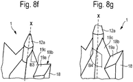
- Fig. 8f shows that the uppermost edge of the sloping section 19c of the land of cutting tooth 18 connecting the cutting edge 18b of cutting tooth 18 to the portion below cone 12a of wall plug 1 forms an angle B3 of approximately 30 degrees with rotational axis X.
- Fig. 8g shows that the upper part of section 19c of the land of cutting tooth 18 is inclined by an angle B4 of approximately 130 degrees relative to the rotational axis X of wall plug 1.
Description
- The invention relates to a self-drilling wall plug for screwing in, according to the preamble of
claim 1. - Such self-drilling wall plugs are known from the prior art.
Publications EP 0 575 295 A ,EP 0 874 165 A ,EP 0 965 767 A ,EP 0 165 674 A ,EP 1 669 615 AEP 1 298 331 A - The object of the invention is to provide a self-drilling wall plug of the kind initially specified, which is an improvement on self-drilling wall plugs of the known kind.
- This object is achieved by a self-drilling wall plug according to
independent claim 1. - The cup disposed according to the invention in the tip region of the self-drilling wall plug, for receiving the front end of a fixing element penetrating the wall plug, allows the front end of the fixing element penetrating the wall plug, for example the front end of a screw which is screwed into the wall plug, to be guided in a specific manner for the first time ever.
- A preferred embodiment of the invention is one in which the cup is substantially cone-shaped.
- Another preferred embodiment of the invention is one in which substantially only one half of the cup is substantially cone-shaped.
- Yet another preferred embodiment of the invention is one in which the cup is designed such that it resists a fixing element penetrating the wall plug with a greater cut-through resistance on a first side, in particular on a first half, than on a second side, in particular on the second half. It is possible in this way to specify systematically on which side a fixing element penetrating the wall plug, for example a screw screwed into it, cuts through the wall of the cup and is thus guided in a targeted manner onto a specific side or half of the cup which has a lower cut-through resistance.
- A preferred embodiment of the invention is one in which the greater cut-through resistance is provided on the one side by a greater wall thickness of the cup compared to the other side. This also achieves the advantage that a fixing element penetrating the wall plug, for example a screw, breaks out of the cup, or breaks through the wall of the cup, on the side with the smaller wall thickness, when the front end of the fixing element penetrates the cup. In this way, the fixing element penetrating the cup is steered to a particular side, in this case to the side with the thinner wall thickness.
- According to the invention a rotational axis of the cup is non-coaxial with a rotational axis of the wall plug. Due to the rotational axis of the cup being arranged non-coaxially, the overall orientation of the cup advantageously ensures that a front end of a fixing element screwed into the wall plug and penetrating the cup exits the wall plug to one side of the front tip of the wall plug.
- According to the invention the rotational axis of the cup is arranged at an angle of preferably 5 to 10 degrees, even more preferably of approximately 6.5 degrees to the rotational axis of the wall plug. The aforementioned angular ranges have proved to be an optimal range within which it is possible to systematically deflect a front end of a fixing element penetrating the wall plug, while simultaneously ensuring that not too much resistance is given to the front end of the fixing element penetrating the wall plug.
- A preferred embodiment of the invention is one in which the cup has at least two preferably non-rotationally symmetric areas on its inner surface. As a result of this inventive design of the inner surface of the cup, the front end of a fixing element penetrating the cup can be deflected in a particular direction, for example to prevent the front end of a fixing element penetrating the cup from striking from behind a pre-drilling element which is arranged on the front end of the wall plug.
- A preferred embodiment of the invention is one in which at least two preferably substantially symmetrically arranged cutting teeth like milling tools are provided in the region of the front end comprising the tip. Improved cutting of board, for example of a plasterboard wall, is achieved with the help of such cutting teeth.
- Another preferred embodiment of the invention is one in which the at least one cutting tooth has an outer surface which is substantially flush with an outer surface of the plug body, which does not have the thread. In this way, the capacity of the wall plug to cut through board, for example of a plasterboard wall, is systematically improved.
- A preferred embodiment of the invention is one in which the at least one cutting tooth has a land which is offset. This provides more space for the borehole debris or plaster dust that is produced in that region, so that the borehole debris or plaster dust can be conveyed more easily into the rear region of the wall plug. This also results in the tip of the wall plug breaking off less easily.
- A preferred embodiment of the invention is one in which one end of the longitudinal ribs of the inner profile, facing the tip, is arranged at a distance from the tip which is substantially equal to the distance to an end of the cutting thread facing the tip. The advantageous result of this positioning of the front end of the longitudinal ribs of the inner profile is that the insertion torque for a screw to be screwed into the wall plug is not too great, thus preventing any slippage of the wall plug. Compared to the longitudinal ribs known from the prior art, this positioning of the front end of the longitudinal ribs of the inner profile in accordance with the invention equates to offsetting the front end forwards towards the tip of the wall plug.
- A preferred embodiment of the invention is one in which pivotable wall portions are provided in wall openings in the plug body, which have a region which projects into an interior space provided inside the inner wall of the plug body, such that the wall portions can be pressed outwards into an anchoring position by a fixing element penetrating the wall plug. This provides additional anchorage of the wall plug in the lightweight building material.
- A preferred embodiment of the invention is one in which the wall portion, on at least the side facing the front end of the wall plug, has a linear notch running substantially circumferentially.
- A preferred embodiment of the invention is one in which the linear notch forms a hinge-like connection, between the wall portion and the plug body, for an at least outwardly directed hinging motion of the wall portion.
- Special embodiments of the invention shall now be described by way of example and with reference to the attached Figures, in which identical or functionally identical parts are marked with the same reference signs, and in which:
- Fig. 1
- shows an overall perspective view of an embodiment of a wall plug according to the invention;
- Fig. 2
- shows a cross-section through the wall plug of
Fig. 1 , the sectional plane being chosen such that the cutting tooth that can be seen on the upper side of the Figure lies behind the sectional plane and thus remains visible, whereas the cutting tooth on the lower side inFig. 1 lies in front of the sectional plane and is therefore no longer visible; - Fig. 3
- shows an enlarged view of the cross-section shown in
Fig. 2 ; - Fig. 4
- shows a side view of the wall plug shown in
Figs. 1 - 3 ; - Fig. 5
- shows a partial section through a front section of the side view in
Fig. 4 , where the upper cutting tooth shown inFig. 4 is in front of the sectional plane and is therefore invisible; - Fig. 6
- shows a perspective view of the cup of the wall plug shown in
Figs. 1 - 5 ; - Fig. 7
- shows a perspective view of the wall plug shown in
Figs. 1 - 6 , viewed from an angle from the front, onto a front section of the wall plug compared to a corresponding view of a prior art wall plug, shown on the right; - Fig. 8a
- shows a top view onto the front end of
wall plug 1 as shown inFigs. 1 - 6 , withtip 12; - Fig. 8b
- shows a side view of the wall plug in
Figs. 1 - 6 , showing preferred dimensions and ratios of lengths; - Fig. 8c
- shows a partial view of the wall plug in
Figs. 1 - 6 for showing preferred dimensioning; and - Figs. 8d - 8g
- show perspective partial views onto the front end of the wall plug in
Figs. 1 - 6 , withtip 12. -
Fig. 1 shows a perspective view of awall plug 1 according to a first embodiment of the invention. Thewall plug 1 inFig. 1 is a self-drilling wall plug 1 for screwing into lightweight building materials, such as plaster walls or the like.Wall plug 1 has a sleeve-shaped plug body 4 surrounded by acutting thread 2. On its rear side, i.e. at its rear end shown on the right in the Figure,wall plug 1 has aflange 6 by means of which thewall plug 1 screwed substantially completely into a wall of the aforementioned kind supports itself at the surface of such a wall. - Viewed from right to left in
Fig. 1 , an outer surface or circumferential surface 8 ofplug body 4 tapers slightly in a conical shape. Cuttingthread 2 extends with approximately three turns over the larger part of the length ofplug body 4 and ends at the front end, shown on the left inFig. 1 , a significant distance A from afront end 10 ofwall plug 1, having atip 12.Wall plug 1 thus has a front leadingportion 14 of length A and free of cutting thread, by means of whichwall plug 1 is guided in a hole which is prepared, in particular, by thefront end 10 ofwall plug 1 havingtip 12. The flank angle ofouter cutting thread 2 is relatively sharp, and the pitch angle is relatively small. Cuttingthread 2 also hasrecesses 16 which open towards the circumferential surface 8 ofplug body 4, and which serve, inter alia, as a means for conveying the borehole debris that is produced. - In the region of the
front end 10 havingtip 12, thewall plug 2 has two cuttingteeth teeth Figs. 1 ,4 and from the partial view shown on the left inFig. 7 , the two cuttingteeth wall plug 1. Each of the two cuttingteeth outer side plug body 4 which does not have the thread. - As can be seen from
Fig. 1 and fromFigs. 8 , cuttingteeth - In addition, cutting
teeth Fig. 1 ,Fig. 7 andFigs. 8 preferably have a land consisting of slopingsections straight sections sloping section 19a of the land preferably lies immediately adjacent to cuttingedge tooth flange 6, by thestraight section 19b of the land, i.e. the section extending parallel to rotational axis X. Laterally fromsections sections section 19c of the land. However,section 19c preferably extends from immediately beforestraight section 19b - viewed from flange 6 - beyondsection 19a, viewed fromflange 6 along rotational axis X, towards the tip ofwall plug 12, as can be seen well fromFigs. 1 and7 .Straight section 19b preferably adjoins once again then, on the side ofsection 19c facing away fromtip 12, i.e. on the side ofsection 19c facing towardsflange 6. - The land of cutting
teeth sections straight sections - Other preferred geometrical relationships in the region of cutting
teeth lands Figs. 8 . - To enable
wall plug 1 according to the invention to be drilled or screwed directly into a wall of the kind initially specified, without previous use of a drilling tool, i.e. without having to pre-drill a hole, a steppedpre-drilling element 22 is provided at thefront end 10 ofhollow plug body 4. The stepping inpre-drilling element 22 is provided by two different sharp angles, with a smaller sharp angle of approximately 17 degrees relative to rotational axis X at the foremost part ofpre-drilling element 22 and with a larger sharp angle of approximately 30 degrees relative to rotational axis X at the rear part ofpre-drilling element 22. The part of thesloping section 19c of the land which extends from thecutting edge tip 12 preferably forms the rear part ofpre-drilling element 22, whereas the final, rotationallysymmetric portion 12a ofwall plug 1, ending attip 12, preferably forms the foremost part ofpre-drilling element 22. - With the help of
pre-drilling element 22 andlateral cutting teeth hollow plug body 4. It has proved particularly advantageous and it is therefore preferred when thesecond ledge 19d ofland land section 19b which is closer to cuttingedge flange 6. - In order that the borehole debris or the borehole cuttings that ensue can enter the interior of
plug body 4, the latter is designed to be open not only to thefront end 10, but additionally hasopenings 24 in its wall. To further improve the transportation of the borehole debris intoopenings 24, the outer or circumferential surface 8 ofplug body 4 is also provided with a conveyingthread 26 which conveys the borehole debris from left to right inFig. 1 when theinventive wall plug 1 is screwed in. - An outer diameter of cutting
thread 2 is preferably twice as large as that ofplug body 4, thus resulting in good anchoring ofwall plug 1 in a soft building material, for example in a gypsum wall. Cuttingthread 2 also supports the driving force when drilling into building material. - In
wall openings 24 provided in thewall 23 ofplug body 4,pivotable wall portions 25 are provided which have a region which projects into aninterior space 27 provided inside theinner wall 30 ofplug body 4, such thatwall portions 25 can be pressed outwards into an anchoring position by a fixing element penetratingwall plug 1.Wall portions 25 are preferably in a region which extends fromflange 6, measured along rotational axis X towardstip 12, between about 20% and about 30% of the plug length, more preferably between about 22% and about 26%, or between about 28% and about 38% of the plug length, and even more preferably between about 30% and about 34% of the plug length. In the preferred embodiment shown inFig. 1 , onewall portion 25 is arranged on one side of the wall plug at a position which lies at about 22% to about 26% of the plug length, whereas awall portion 25 arranged on the opposite side of the wall plug is arranged at a position which lies at about 30% to about 34% of the plug length. The longitudinal extension ofwall elements 25, measured in the direction of rotational axis X ofwall plug 1, preferably amounts to approximately 6% to approximately 8% of the total length of the wall plug. The width ofwall elements 25, measured in the circumferential direction of the wall plug, is preferably about 4% to about 7% of the total length of the wall plug. -
Wall portion 25, on at least its side facing thefront end 10 ofwall plug 1, has alinear notch 25a running substantially circumferentially. -
Linear notch 25a forms a hinge-like connection betweenwall portion 25 and plugbody 4, for an at least outwardly directed hinging motion ofwall portion 25. - In its
flange 6,wall plug 1 has arecess 28 for engaging a driving tool. In the embodiment shown inFig. 1 ,recess 28 is cross-slotted so that bit driving tools can be used that are well-known on the market. However, all other kinds ofrecess 28 for receiving matching driving tools are also conceivable. -
Plug body 4 also has an inner profile formed by a plurality oflongitudinal ribs 32 along itsinner wall 30, into which the thread of a fixing element to be inserted intowall plug 1 can cut. - In the region of
front end 10, preferably directly behindpre-drilling element 22,wall plug 1 according to the invention has acup 28 for receiving a front end or a tip of a fixing element which penetrateswall plug 1. It is preferable thatcup 38 is substantially cone-shaped. It is further preferred that substantially only one half ofcup 38 is substantially cone-shaped.Cup 38 is also preferably designed such that it resists a fixing element penetratingwall plug 1 with a greater cut-through resistance on a first side, in particular on a first half, than on a second side, in particular on a second half. This greater cut-through resistance is preferably provided bycup 38 having a thicker wall thickness on the one side, preferably on its one half, than on the other side, preferably the other half. - A
rotational axis 44 ofcup 38 is not coaxial with a rotational axis X ofwall plug 1. Instead, and as shown inFig. 3 , therotational axis 44 ofcup 38 is arranged at an angle (α) of preferably 5 to 10 degrees, even more preferably of approximately 6.5 degrees to the rotational axis ofwall plug 1. Due to therotational axis 44 ofcup 38 being slightly tilted relative to the rotational axis X ofwall plug 1, a screw penetrating with its tip intocup 38 ofwall plug 1 is guided to one side in a targeted manner, then guided outwards, preferably in a targeted manner, through the side with the thinner wall, by the tip of the screw then breaking through this thinner wall on the respective side. - It is also preferable that
cup 38 according to the invention can have a plurality ofareas inner surface 40, as shown inFig. 6 . Theseareas 40a - 40d are preferably not rotationally symmetric. -
Fig. 2 shows a cross-section throughwall plug 1 ofFig. 1 , the sectional plane being chosen such that the cuttingtooth 18 that can be seen on the upper side inFig. 2 lies behind the sectional plane and thus remains visible, whereas cuttingtooth 20 on the lower side inFig. 1 lies in front of the sectional plane and is therefore no longer visible. -
Fig. 3 shows an enlarged view of the cross-section shown inFig. 2 . It shows the angle α by which therotational axis 44 ofcup 38 is tilted relative to the rotational axis X ofwall plug 1. -
Fig. 4 shows a side view of the wall plug shown inFigs. 1 - 3 . -
Fig. 5 shows a partial section through a front section of the side view inFig. 4 , where theupper cutting tooth 18 shown inFig. 4 is in front of the sectional plane and therefore remains invisible. -
Fig. 6 shows a perspective view of the cup ofwall plug 1 shown inFigs. 1 - 5 ; in whichareas 40a - 40d of theinner surface 40 ofcup 38 can be seen well. -
Fig. 7 shows a perspective view of thewall plug 1 shown inFigs. 1 - 6 , viewed from an angle from the front, onto afront section 14 of the wall plug compared to a corresponding view of a prior art wall plug, shown on the right. It is clear from this view that thelower section 19d of the land ofwall plug 1 according to the invention, shown on the left, differs from theland 46 of the prior art wall plug, shown on the right, in thatsection 19d inwall plug 1 according to the invention has a surface which is oriented parallel to the surface ofsection 19b of the land of cuttingtooth 18 that lies further up, whereas thesurface 46 of the land of the wall plug shown on the right is not parallel to thecorresponding surface 48. -
Fig. 8a shows a top view onto the front end ofwall plug 1, withtip 12, as shown inFigs. 1 - 6 . More particularly,Fig. 8a shows that the ledges orsections Fig. 8a , preferably have surfaces which are oriented mutually parallel to each other.Fig. 8a also shows the preferred position ofland 19a offset fromtip 12 and directly adjoiningcutting edge 18b.Land 19a is preferably separated from cone ofrotation 12a by the slopingland 19c that extends as far as the cone ofrotation 12a underneathtip 12. -
Fig. 8a also shows the distance a of thelowermost section 19d of the land from cuttingedge 18b and the distance b of the lowermost ledge orsection 19d of the land from the greatest outer periphery ofwall plug 1 as defined byflange 6, likewise measured perpendicularly to cuttingedge 18b. The sum of "a+b" is the radius of the largest outer diameter ofwall plug 1, as measured atflange 6. The value for distance a is preferably between 20 and 30% of radius r=a+b. The value for b is preferably between about 70 and about 80% of radius r=a+b. The distance of the ledge orsection 19b from cuttingedge 18b is preferably about half of a. The opening angle α1, viewed from the tip, between a line drawn fromtip 12 or rotational axis X through cuttingedge 18b, and a line drawn fromtip 12 or rotational axis X through the most distant corner ofland 19a is preferably between about 15 degrees and about 20 degrees, even more preferably about 18 degrees. Angle β between a line drawn from rotational axis X through cuttingedge 18b, and the edge of the lowermost ledge orsection 19d most distant from rotational axis X is preferably about 30 degrees to about 40 degrees, even more preferably about 37 degrees. - Similar measurements and dimensioning are likewise preferred, in mirror-symmetrical form relative to rotational axis X, for the design of cutting
tooth 20 withcutting edge 20b andlands -
Fig. 8b shows a side view of the wall plug inFigs. 1 - 6 , showing preferred dimensions and ratios of lengths.Fig. 8b shows that the end ofcup 38 closest to thetip 12 ofwall plug 1 is preferably positioned at a distance c fromtip 12, said distance c preferably being about 8% to about 10% of plug length G, measured from thetip 12. -
Fig. 8b also shows that the end ofcup 38 closest to the end orflange 6 ofwall plug 1 is preferably positioned at a distance d, said distance d being approximately 15% to about 18% of plug length G, measured from thetip 12. -
Fig. 8b also shows that length e along rotational axis X is preferably about 6% to about 9% of the total length G ofwall plug 1. -
Fig. 8b also shows that the total length f of the lowermost ledge orsection 19d of the land of cuttingteeth wall plug 1. -
Fig. 8b also shows that length f is preferably approximately equal to length e, and that length f is even more preferably 1.1 to 1.2 times length e. -
Fig. 8b also shows that it is preferred that distance g between the bottom edge of thelowermost section 19d of the land, facingflange 6, and the tip of cuttingedge 18b closest along rotational axis X is preferably equal to about 1.5 to 2 times distance f. -
Fig. 8c shows a partial view of the wall plug inFigs. 1 - 6 for showing preferred dimensioning. According toFig. 8c , it is preferred that the length h of cuttingedges teeth wall plug 1. According toFig. 8c , it is further preferred that the angle γ betweencutting edge 18b and the slope of thelower edge 50 of the land, facing away from thetip 12 ofwall plug 1, is between about 100 degrees and about 115 degrees. -
Figs. 8d - 8g show perspective partial views onto the front end of the wall plug inFigs. 1 - 6 , withtip 12.Fig. 8d shows that the relative angle B1 between the slope of that part ofsection 19c lying betweenledges tooth 18, and rotational axis X, is about 35 degrees. -
Fig. 8e shows that the angle B2 by which the upper part ofsection 19c of the land of cuttingtooth 18 is inclined relative tosection 19a of the land is approximately 130 degrees. -
Fig. 8f shows that the uppermost edge of thesloping section 19c of the land of cuttingtooth 18 connecting thecutting edge 18b of cuttingtooth 18 to the portion belowcone 12a ofwall plug 1 forms an angle B3 of approximately 30 degrees with rotational axis X. -
Fig. 8g shows that the upper part ofsection 19c of the land of cuttingtooth 18 is inclined by an angle B4 of approximately 130 degrees relative to the rotational axis X ofwall plug 1.
Claims (14)
- A self-drilling wall plug (1) for screwing into lightweight building materials, in particular into plaster walls, having a sleeve-shaped plug body (4) surrounded by a cutting thread (2), a flange (6) on the rear side, at least one cutting tooth (18, 20) like a milling tool in the region of its front end (10) comprising a tip (12), an inner profile formed along an inner wall (30) by a plurality of longitudinal ribs (32), into which the thread of a fixing element cuts, and in its flange (6) a recess (28) for engaging a driving tool,
comprising a cup (38) for receiving the front end of a fixing element penetrating the wall plug (1) and which is provided in the region of the front end of the latter, characterised in that a rotational axis (44) of the cup (38) is non-coaxial with a rotational axis (X) of the wall plug, wherein the rotational axis (44) of the cup (38) is arranged at an angle (α) to the rotational axis (X) of the wall plug (1). - The wall plug (1) according to claim 1,
wherein the cup (38) is substantially cone-shaped. - The wall plug (1) according to any one of the preceding claims,
wherein substantially only one half of the cup (38) is substantially cone-shaped. - The wall plug (1) according to any one of the preceding claims,
wherein the cup (38) is designed such that it resists a fixing element penetrating the wall plug (1) with a greater cut-through resistance on a first side, in particular on a first half, than on a second side, in particular on the second half. - The wall plug (1) according to the preceding claim,
wherein the greater cut-through resistance is provided on the one side by a greater wall thickness of the cup (38) compared to the other side. - The wall plug (1) according to the preceding claim,
wherein the rotational axis (44) of the cup (38) is arranged at an angle (α) of 5 to 10 degrees, preferably of approximately 6.5 degrees to the rotational axis (X) of the wall plug (1). - The wall plug (1) according to any one of the preceding claims,
wherein the cup (38) has at least two preferably non-rotationally symmetric areas (40a, 40b, 40c, 40d) on its inner surface. - The wall plug (1) according to any one of the preceding claims,
wherein at least two preferably substantially symmetrically arranged cutting teeth (18, 20) like milling tools are provided in the region of its front end (10) comprising the tip (12). - The wall plug (1) according to any one of the preceding claims,
wherein the at least one cutting tooth (18, 20) has an outer surface (18a, 20a) which is substantially flush with an outer surface (8) of the plug body (4), which does not have the thread. - The wall plug (1) according to any one of the preceding claims,
wherein the at least one cutting tooth (18, 20) has a land (19a, 19b, 19c, 19d) consisting of at least four sections (19a, 19b, 19c, 19d), wherein at least two of said sections (19a, 19b, 19c, 19d) have surfaces which lie in planes parallel to each other. - The wall plug (1) according to any one of the preceding claims,
wherein one end of the longitudinal ribs (32) of the inner profile, facing the tip (12), is arranged at a distance from the tip (12) which is substantially equal to the distance to an end of the cutting thread (2) facing the tip (12). - The wall plug (1) according to any one of the preceding claims,
wherein pivotable wall portions (25) are provided in wall openings (24) in the plug body (4), which have a region which projects into an interior space (27) provided inside the inner wall (30) of the plug body (4), such that the wall portions (25) can be pressed outwards into an anchoring position by a fixing element penetrating the wall plug (1). - The wall plug (1) according to the preceding claim,
wherein the wall portion (25), on at least the side facing the front end (10) of the wall plug (1), has a linear notch (25a) running substantially circumferentially. - The wall plug (1) according to the preceding claim,
wherein the linear notch (25a) forms a hinge-like connection, between the wall portion (25) and the plug body (4), for an at least outwardly directed hinging motion of the wall portion (25).
Priority Applications (2)
| Application Number | Priority Date | Filing Date | Title |
|---|---|---|---|
| PL18705113.1T PL3749866T3 (en) | 2018-02-07 | 2018-02-07 | Self-drilling wall plug |
| SI201830801T SI3749866T1 (en) | 2018-02-07 | 2018-02-07 | Self-drilling wall plug |
Applications Claiming Priority (1)
| Application Number | Priority Date | Filing Date | Title |
|---|---|---|---|
| PCT/EP2018/053036 WO2019154485A1 (en) | 2018-02-07 | 2018-02-07 | Self-drilling wall plug |
Publications (2)
| Publication Number | Publication Date |
|---|---|
| EP3749866A1 EP3749866A1 (en) | 2020-12-16 |
| EP3749866B1 true EP3749866B1 (en) | 2022-08-10 |
Family
ID=61223891
Family Applications (1)
| Application Number | Title | Priority Date | Filing Date |
|---|---|---|---|
| EP18705113.1A Active EP3749866B1 (en) | 2018-02-07 | 2018-02-07 | Self-drilling wall plug |
Country Status (7)
| Country | Link |
|---|---|
| US (1) | US20210040971A1 (en) |
| EP (1) | EP3749866B1 (en) |
| JP (1) | JP2021513033A (en) |
| ES (1) | ES2932275T3 (en) |
| PL (1) | PL3749866T3 (en) |
| SI (1) | SI3749866T1 (en) |
| WO (1) | WO2019154485A1 (en) |
Families Citing this family (4)
| Publication number | Priority date | Publication date | Assignee | Title |
|---|---|---|---|---|
| US20200173482A1 (en) * | 2018-11-29 | 2020-06-04 | The Hillman Group, Inc. | Wallboard anchor |
| US11209037B2 (en) * | 2019-07-03 | 2021-12-28 | David Adams | Screw and anchor assembly |
| AU2020200215B1 (en) * | 2020-01-10 | 2021-04-15 | Taiwan Shan Yin International Co., Ltd. | Self-Drilling Screw |
| USD985421S1 (en) * | 2021-05-07 | 2023-05-09 | Classic Home & Garden, LLC | Plug |
Family Cites Families (15)
| Publication number | Priority date | Publication date | Assignee | Title |
|---|---|---|---|---|
| US4601625A (en) * | 1984-05-11 | 1986-07-22 | Illinois Tool Works Inc. | Self drilling threaded insert for drywall |
| US5267423A (en) * | 1987-08-03 | 1993-12-07 | Giannuzzi Louis | Self-drilling anchor and bearing plate assembly |
| US5234299A (en) * | 1987-08-03 | 1993-08-10 | Giannuzzi Louis | Self-drilling anchor |
| JPH0547847Y2 (en) * | 1988-09-26 | 1993-12-17 | ||
| FR2673251B1 (en) * | 1991-02-25 | 1994-07-08 | Legrand Sa | SCREWS, PARTICULARLY HOLLOW FUT SCREWS OF THE ANKLE SCREW TYPE FOR SOFT MATERIAL. |
| CH686637A5 (en) | 1992-06-18 | 1996-05-15 | Mungo Befestigungstech Ag | Schraubhulse. |
| DE19717420A1 (en) | 1997-04-25 | 1998-10-29 | Mungo Befestigungstech Ag | Fixing device |
| DK79098A (en) | 1998-06-15 | 1999-12-16 | Tillegreen Poul | Self-drilling dove |
| US6382892B1 (en) * | 2001-01-16 | 2002-05-07 | Dave C. Hempfling | Wall anchor with improved drilling tip |
| ATE329163T1 (en) | 2001-10-01 | 2006-06-15 | Mungo Befestigungstech Ag | SCREW DOWEL |
| US7934895B2 (en) * | 2003-10-10 | 2011-05-03 | Illinois Tool Works Inc. | Self-drilling anchor |
| US20050084360A1 (en) * | 2003-10-10 | 2005-04-21 | Panasik Cheryl L. | Self-drilling anchor |
| JP2005179913A (en) * | 2003-12-16 | 2005-07-07 | Mungo Befestigungstechnik Ag | Screw-in sleeve |
| US20060165506A1 (en) * | 2004-02-05 | 2006-07-27 | Panasik Cheryl L | Anchor |
| CH697361B1 (en) * | 2004-12-10 | 2008-08-29 | Mungo Befestigungstech Ag | A threaded insert. |
-
2018
- 2018-02-07 ES ES18705113T patent/ES2932275T3/en active Active
- 2018-02-07 US US16/966,828 patent/US20210040971A1/en not_active Abandoned
- 2018-02-07 WO PCT/EP2018/053036 patent/WO2019154485A1/en unknown
- 2018-02-07 PL PL18705113.1T patent/PL3749866T3/en unknown
- 2018-02-07 SI SI201830801T patent/SI3749866T1/en unknown
- 2018-02-07 JP JP2020535573A patent/JP2021513033A/en active Pending
- 2018-02-07 EP EP18705113.1A patent/EP3749866B1/en active Active
Also Published As
| Publication number | Publication date |
|---|---|
| JP2021513033A (en) | 2021-05-20 |
| SI3749866T1 (en) | 2023-02-28 |
| PL3749866T3 (en) | 2023-02-20 |
| EP3749866A1 (en) | 2020-12-16 |
| US20210040971A1 (en) | 2021-02-11 |
| ES2932275T3 (en) | 2023-01-17 |
| WO2019154485A1 (en) | 2019-08-15 |
Similar Documents
| Publication | Publication Date | Title |
|---|---|---|
| EP3749866B1 (en) | Self-drilling wall plug | |
| US5160225A (en) | Structure of a self-drilling threaded insert for use on drywall | |
| CA2631156C (en) | Anchor | |
| US10605289B2 (en) | Screw with cutting teeth | |
| EP1727990B1 (en) | Self-drilling anchor | |
| US7290972B2 (en) | Screw anchor for friable material | |
| CA2364076C (en) | Wall anchor with improved drilling tip | |
| US20060285940A1 (en) | Screw For Use In Concrete | |
| JP2008537989A (en) | Tapping concrete screw | |
| US20060127199A1 (en) | Screwed insert | |
| US10954987B2 (en) | Plug screw | |
| ES2702153T3 (en) | Screw for wood with intermediate sections of thread that are narrowed towards the front | |
| EP0469290B1 (en) | Threaded insert for use on a drywall | |
| US20040052606A1 (en) | Dowell for lightweight building materials and use of a screw driver bit for screwing in such dowels | |
| EP1493929B1 (en) | Wall plug | |
| EP2039845B1 (en) | Mounting element for attaching insulation boards to a substructure | |
| EP3855026A1 (en) | Screw | |
| TW202028621A (en) | Wallboard anchor | |
| AU669986B2 (en) | Improved self-drilling wall anchor | |
| JP2002039134A (en) | Tapping screw | |
| US11293475B2 (en) | Screw | |
| US20030138306A1 (en) | Self-drilling insert | |
| JP2005179913A (en) | Screw-in sleeve | |
| GB2564450A (en) | A fastener |
Legal Events
| Date | Code | Title | Description |
|---|---|---|---|
| STAA | Information on the status of an ep patent application or granted ep patent |
Free format text: STATUS: UNKNOWN |
|
| STAA | Information on the status of an ep patent application or granted ep patent |
Free format text: STATUS: THE INTERNATIONAL PUBLICATION HAS BEEN MADE |
|
| PUAI | Public reference made under article 153(3) epc to a published international application that has entered the european phase |
Free format text: ORIGINAL CODE: 0009012 |
|
| STAA | Information on the status of an ep patent application or granted ep patent |
Free format text: STATUS: REQUEST FOR EXAMINATION WAS MADE |
|
| 17P | Request for examination filed |
Effective date: 20200907 |
|
| AK | Designated contracting states |
Kind code of ref document: A1 Designated state(s): AL AT BE BG CH CY CZ DE DK EE ES FI FR GB GR HR HU IE IS IT LI LT LU LV MC MK MT NL NO PL PT RO RS SE SI SK SM TR |
|
| AX | Request for extension of the european patent |
Extension state: BA ME |
|
| RIN1 | Information on inventor provided before grant (corrected) |
Inventor name: PIROZZI, MASSIMO |
|
| DAV | Request for validation of the european patent (deleted) | ||
| DAX | Request for extension of the european patent (deleted) | ||
| GRAP | Despatch of communication of intention to grant a patent |
Free format text: ORIGINAL CODE: EPIDOSNIGR1 |
|
| STAA | Information on the status of an ep patent application or granted ep patent |
Free format text: STATUS: GRANT OF PATENT IS INTENDED |
|
| INTG | Intention to grant announced |
Effective date: 20220221 |
|
| GRAS | Grant fee paid |
Free format text: ORIGINAL CODE: EPIDOSNIGR3 |
|
| GRAA | (expected) grant |
Free format text: ORIGINAL CODE: 0009210 |
|
| STAA | Information on the status of an ep patent application or granted ep patent |
Free format text: STATUS: THE PATENT HAS BEEN GRANTED |
|
| AK | Designated contracting states |
Kind code of ref document: B1 Designated state(s): AL AT BE BG CH CY CZ DE DK EE ES FI FR GB GR HR HU IE IS IT LI LT LU LV MC MK MT NL NO PL PT RO RS SE SI SK SM TR |
|
| REG | Reference to a national code |
Ref country code: AT Ref legal event code: REF Ref document number: 1510742 Country of ref document: AT Kind code of ref document: T Effective date: 20220815 Ref country code: CH Ref legal event code: EP |
|
| REG | Reference to a national code |
Ref country code: DE Ref legal event code: R096 Ref document number: 602018039048 Country of ref document: DE |
|
| REG | Reference to a national code |
Ref country code: IE Ref legal event code: FG4D |
|
| REG | Reference to a national code |
Ref country code: NL Ref legal event code: FP |
|
| REG | Reference to a national code |
Ref country code: LT Ref legal event code: MG9D |
|
| REG | Reference to a national code |
Ref country code: ES Ref legal event code: FG2A Ref document number: 2932275 Country of ref document: ES Kind code of ref document: T3 Effective date: 20230117 |
|
| PG25 | Lapsed in a contracting state [announced via postgrant information from national office to epo] |
Ref country code: SE Free format text: LAPSE BECAUSE OF FAILURE TO SUBMIT A TRANSLATION OF THE DESCRIPTION OR TO PAY THE FEE WITHIN THE PRESCRIBED TIME-LIMIT Effective date: 20220810 Ref country code: RS Free format text: LAPSE BECAUSE OF FAILURE TO SUBMIT A TRANSLATION OF THE DESCRIPTION OR TO PAY THE FEE WITHIN THE PRESCRIBED TIME-LIMIT Effective date: 20220810 Ref country code: PT Free format text: LAPSE BECAUSE OF FAILURE TO SUBMIT A TRANSLATION OF THE DESCRIPTION OR TO PAY THE FEE WITHIN THE PRESCRIBED TIME-LIMIT Effective date: 20221212 Ref country code: NO Free format text: LAPSE BECAUSE OF FAILURE TO SUBMIT A TRANSLATION OF THE DESCRIPTION OR TO PAY THE FEE WITHIN THE PRESCRIBED TIME-LIMIT Effective date: 20221110 Ref country code: LV Free format text: LAPSE BECAUSE OF FAILURE TO SUBMIT A TRANSLATION OF THE DESCRIPTION OR TO PAY THE FEE WITHIN THE PRESCRIBED TIME-LIMIT Effective date: 20220810 Ref country code: LT Free format text: LAPSE BECAUSE OF FAILURE TO SUBMIT A TRANSLATION OF THE DESCRIPTION OR TO PAY THE FEE WITHIN THE PRESCRIBED TIME-LIMIT Effective date: 20220810 Ref country code: FI Free format text: LAPSE BECAUSE OF FAILURE TO SUBMIT A TRANSLATION OF THE DESCRIPTION OR TO PAY THE FEE WITHIN THE PRESCRIBED TIME-LIMIT Effective date: 20220810 |
|
| REG | Reference to a national code |
Ref country code: AT Ref legal event code: MK05 Ref document number: 1510742 Country of ref document: AT Kind code of ref document: T Effective date: 20220810 |
|
| PG25 | Lapsed in a contracting state [announced via postgrant information from national office to epo] |
Ref country code: IS Free format text: LAPSE BECAUSE OF FAILURE TO SUBMIT A TRANSLATION OF THE DESCRIPTION OR TO PAY THE FEE WITHIN THE PRESCRIBED TIME-LIMIT Effective date: 20221210 Ref country code: HR Free format text: LAPSE BECAUSE OF FAILURE TO SUBMIT A TRANSLATION OF THE DESCRIPTION OR TO PAY THE FEE WITHIN THE PRESCRIBED TIME-LIMIT Effective date: 20220810 Ref country code: GR Free format text: LAPSE BECAUSE OF FAILURE TO SUBMIT A TRANSLATION OF THE DESCRIPTION OR TO PAY THE FEE WITHIN THE PRESCRIBED TIME-LIMIT Effective date: 20221111 |
|
| PGFP | Annual fee paid to national office [announced via postgrant information from national office to epo] |
Ref country code: NL Payment date: 20230220 Year of fee payment: 6 |
|
| PG25 | Lapsed in a contracting state [announced via postgrant information from national office to epo] |
Ref country code: SM Free format text: LAPSE BECAUSE OF FAILURE TO SUBMIT A TRANSLATION OF THE DESCRIPTION OR TO PAY THE FEE WITHIN THE PRESCRIBED TIME-LIMIT Effective date: 20220810 Ref country code: RO Free format text: LAPSE BECAUSE OF FAILURE TO SUBMIT A TRANSLATION OF THE DESCRIPTION OR TO PAY THE FEE WITHIN THE PRESCRIBED TIME-LIMIT Effective date: 20220810 Ref country code: DK Free format text: LAPSE BECAUSE OF FAILURE TO SUBMIT A TRANSLATION OF THE DESCRIPTION OR TO PAY THE FEE WITHIN THE PRESCRIBED TIME-LIMIT Effective date: 20220810 Ref country code: AT Free format text: LAPSE BECAUSE OF FAILURE TO SUBMIT A TRANSLATION OF THE DESCRIPTION OR TO PAY THE FEE WITHIN THE PRESCRIBED TIME-LIMIT Effective date: 20220810 |
|
| PGFP | Annual fee paid to national office [announced via postgrant information from national office to epo] |
Ref country code: FR Payment date: 20230217 Year of fee payment: 6 Ref country code: ES Payment date: 20230317 Year of fee payment: 6 Ref country code: CZ Payment date: 20230206 Year of fee payment: 6 Ref country code: CH Payment date: 20230307 Year of fee payment: 6 |
|
| REG | Reference to a national code |
Ref country code: DE Ref legal event code: R097 Ref document number: 602018039048 Country of ref document: DE |
|
| PG25 | Lapsed in a contracting state [announced via postgrant information from national office to epo] |
Ref country code: SK Free format text: LAPSE BECAUSE OF FAILURE TO SUBMIT A TRANSLATION OF THE DESCRIPTION OR TO PAY THE FEE WITHIN THE PRESCRIBED TIME-LIMIT Effective date: 20220810 Ref country code: EE Free format text: LAPSE BECAUSE OF FAILURE TO SUBMIT A TRANSLATION OF THE DESCRIPTION OR TO PAY THE FEE WITHIN THE PRESCRIBED TIME-LIMIT Effective date: 20220810 |
|
| PGFP | Annual fee paid to national office [announced via postgrant information from national office to epo] |
Ref country code: TR Payment date: 20230301 Year of fee payment: 6 Ref country code: SI Payment date: 20230206 Year of fee payment: 6 Ref country code: PL Payment date: 20230206 Year of fee payment: 6 Ref country code: IT Payment date: 20230228 Year of fee payment: 6 Ref country code: DE Payment date: 20230308 Year of fee payment: 6 |
|
| PLBE | No opposition filed within time limit |
Free format text: ORIGINAL CODE: 0009261 |
|
| STAA | Information on the status of an ep patent application or granted ep patent |
Free format text: STATUS: NO OPPOSITION FILED WITHIN TIME LIMIT |
|
| PG25 | Lapsed in a contracting state [announced via postgrant information from national office to epo] |
Ref country code: AL Free format text: LAPSE BECAUSE OF FAILURE TO SUBMIT A TRANSLATION OF THE DESCRIPTION OR TO PAY THE FEE WITHIN THE PRESCRIBED TIME-LIMIT Effective date: 20220810 |
|
| 26N | No opposition filed |
Effective date: 20230511 |
|
| PG25 | Lapsed in a contracting state [announced via postgrant information from national office to epo] |
Ref country code: MC Free format text: LAPSE BECAUSE OF FAILURE TO SUBMIT A TRANSLATION OF THE DESCRIPTION OR TO PAY THE FEE WITHIN THE PRESCRIBED TIME-LIMIT Effective date: 20220810 |
|
| REG | Reference to a national code |
Ref country code: BE Ref legal event code: MM Effective date: 20230228 |
|
| GBPC | Gb: european patent ceased through non-payment of renewal fee |
Effective date: 20230207 |
|
| PG25 | Lapsed in a contracting state [announced via postgrant information from national office to epo] |
Ref country code: LU Free format text: LAPSE BECAUSE OF NON-PAYMENT OF DUE FEES Effective date: 20230207 |
|
| REG | Reference to a national code |
Ref country code: IE Ref legal event code: MM4A |
|
| PG25 | Lapsed in a contracting state [announced via postgrant information from national office to epo] |
Ref country code: GB Free format text: LAPSE BECAUSE OF NON-PAYMENT OF DUE FEES Effective date: 20230207 |
|
| PG25 | Lapsed in a contracting state [announced via postgrant information from national office to epo] |
Ref country code: IE Free format text: LAPSE BECAUSE OF NON-PAYMENT OF DUE FEES Effective date: 20230207 Ref country code: GB Free format text: LAPSE BECAUSE OF NON-PAYMENT OF DUE FEES Effective date: 20230207 |
|
| PG25 | Lapsed in a contracting state [announced via postgrant information from national office to epo] |
Ref country code: BE Free format text: LAPSE BECAUSE OF NON-PAYMENT OF DUE FEES Effective date: 20230228 |
|
| PGFP | Annual fee paid to national office [announced via postgrant information from national office to epo] |
Ref country code: ES Payment date: 20240319 Year of fee payment: 7 Ref country code: NL Payment date: 20240228 Year of fee payment: 7 |