EP3749850B1 - Method and system for controlling a wind turbine to manage edgewise blade vibrations - Google Patents
Method and system for controlling a wind turbine to manage edgewise blade vibrations Download PDFInfo
- Publication number
- EP3749850B1 EP3749850B1 EP19704186.6A EP19704186A EP3749850B1 EP 3749850 B1 EP3749850 B1 EP 3749850B1 EP 19704186 A EP19704186 A EP 19704186A EP 3749850 B1 EP3749850 B1 EP 3749850B1
- Authority
- EP
- European Patent Office
- Prior art keywords
- frequency
- whirling mode
- wind turbine
- rotor blade
- threshold value
- Prior art date
- Legal status (The legal status is an assumption and is not a legal conclusion. Google has not performed a legal analysis and makes no representation as to the accuracy of the status listed.)
- Active
Links
- 238000000034 method Methods 0.000 title claims description 88
- 230000033001 locomotion Effects 0.000 claims description 28
- 230000006870 function Effects 0.000 claims description 10
- 230000001133 acceleration Effects 0.000 claims description 7
- 238000001228 spectrum Methods 0.000 claims description 7
- 230000003247 decreasing effect Effects 0.000 claims description 5
- 238000004891 communication Methods 0.000 claims description 3
- 238000004590 computer program Methods 0.000 claims description 2
- 230000010355 oscillation Effects 0.000 description 11
- 238000005259 measurement Methods 0.000 description 9
- 230000009467 reduction Effects 0.000 description 8
- 239000013598 vector Substances 0.000 description 7
- 238000013461 design Methods 0.000 description 5
- 230000007423 decrease Effects 0.000 description 4
- 238000004519 manufacturing process Methods 0.000 description 4
- 238000012544 monitoring process Methods 0.000 description 4
- 238000013459 approach Methods 0.000 description 3
- 230000006399 behavior Effects 0.000 description 3
- 230000005540 biological transmission Effects 0.000 description 3
- 238000013507 mapping Methods 0.000 description 3
- 238000010248 power generation Methods 0.000 description 3
- 238000012935 Averaging Methods 0.000 description 2
- 230000009286 beneficial effect Effects 0.000 description 2
- 238000010586 diagram Methods 0.000 description 2
- 230000000694 effects Effects 0.000 description 2
- 230000000116 mitigating effect Effects 0.000 description 2
- 230000000750 progressive effect Effects 0.000 description 2
- 230000001373 regressive effect Effects 0.000 description 2
- 238000005070 sampling Methods 0.000 description 2
- 238000004088 simulation Methods 0.000 description 2
- OKTJSMMVPCPJKN-UHFFFAOYSA-N Carbon Chemical compound [C] OKTJSMMVPCPJKN-UHFFFAOYSA-N 0.000 description 1
- 229910052799 carbon Inorganic materials 0.000 description 1
- 238000006243 chemical reaction Methods 0.000 description 1
- 238000013154 diagnostic monitoring Methods 0.000 description 1
- 230000006698 induction Effects 0.000 description 1
- 230000003287 optical effect Effects 0.000 description 1
- 230000003534 oscillatory effect Effects 0.000 description 1
- 238000005096 rolling process Methods 0.000 description 1
- 230000003595 spectral effect Effects 0.000 description 1
- 238000012956 testing procedure Methods 0.000 description 1
Images


Classifications
-
- F—MECHANICAL ENGINEERING; LIGHTING; HEATING; WEAPONS; BLASTING
- F03—MACHINES OR ENGINES FOR LIQUIDS; WIND, SPRING, OR WEIGHT MOTORS; PRODUCING MECHANICAL POWER OR A REACTIVE PROPULSIVE THRUST, NOT OTHERWISE PROVIDED FOR
- F03D—WIND MOTORS
- F03D7/00—Controlling wind motors
- F03D7/02—Controlling wind motors the wind motors having rotation axis substantially parallel to the air flow entering the rotor
- F03D7/0296—Controlling wind motors the wind motors having rotation axis substantially parallel to the air flow entering the rotor to prevent, counteract or reduce noise emissions
-
- F—MECHANICAL ENGINEERING; LIGHTING; HEATING; WEAPONS; BLASTING
- F03—MACHINES OR ENGINES FOR LIQUIDS; WIND, SPRING, OR WEIGHT MOTORS; PRODUCING MECHANICAL POWER OR A REACTIVE PROPULSIVE THRUST, NOT OTHERWISE PROVIDED FOR
- F03D—WIND MOTORS
- F03D7/00—Controlling wind motors
- F03D7/02—Controlling wind motors the wind motors having rotation axis substantially parallel to the air flow entering the rotor
- F03D7/0204—Controlling wind motors the wind motors having rotation axis substantially parallel to the air flow entering the rotor for orientation in relation to wind direction
-
- F—MECHANICAL ENGINEERING; LIGHTING; HEATING; WEAPONS; BLASTING
- F03—MACHINES OR ENGINES FOR LIQUIDS; WIND, SPRING, OR WEIGHT MOTORS; PRODUCING MECHANICAL POWER OR A REACTIVE PROPULSIVE THRUST, NOT OTHERWISE PROVIDED FOR
- F03D—WIND MOTORS
- F03D7/00—Controlling wind motors
- F03D7/02—Controlling wind motors the wind motors having rotation axis substantially parallel to the air flow entering the rotor
- F03D7/022—Adjusting aerodynamic properties of the blades
- F03D7/0224—Adjusting blade pitch
-
- F—MECHANICAL ENGINEERING; LIGHTING; HEATING; WEAPONS; BLASTING
- F03—MACHINES OR ENGINES FOR LIQUIDS; WIND, SPRING, OR WEIGHT MOTORS; PRODUCING MECHANICAL POWER OR A REACTIVE PROPULSIVE THRUST, NOT OTHERWISE PROVIDED FOR
- F03D—WIND MOTORS
- F03D7/00—Controlling wind motors
- F03D7/02—Controlling wind motors the wind motors having rotation axis substantially parallel to the air flow entering the rotor
- F03D7/0244—Controlling wind motors the wind motors having rotation axis substantially parallel to the air flow entering the rotor for braking
-
- F—MECHANICAL ENGINEERING; LIGHTING; HEATING; WEAPONS; BLASTING
- F03—MACHINES OR ENGINES FOR LIQUIDS; WIND, SPRING, OR WEIGHT MOTORS; PRODUCING MECHANICAL POWER OR A REACTIVE PROPULSIVE THRUST, NOT OTHERWISE PROVIDED FOR
- F03D—WIND MOTORS
- F03D7/00—Controlling wind motors
- F03D7/02—Controlling wind motors the wind motors having rotation axis substantially parallel to the air flow entering the rotor
- F03D7/0276—Controlling wind motors the wind motors having rotation axis substantially parallel to the air flow entering the rotor controlling rotor speed, e.g. variable speed
-
- F—MECHANICAL ENGINEERING; LIGHTING; HEATING; WEAPONS; BLASTING
- F05—INDEXING SCHEMES RELATING TO ENGINES OR PUMPS IN VARIOUS SUBCLASSES OF CLASSES F01-F04
- F05B—INDEXING SCHEME RELATING TO WIND, SPRING, WEIGHT, INERTIA OR LIKE MOTORS, TO MACHINES OR ENGINES FOR LIQUIDS COVERED BY SUBCLASSES F03B, F03D AND F03G
- F05B2220/00—Application
- F05B2220/30—Application in turbines
-
- F—MECHANICAL ENGINEERING; LIGHTING; HEATING; WEAPONS; BLASTING
- F05—INDEXING SCHEMES RELATING TO ENGINES OR PUMPS IN VARIOUS SUBCLASSES OF CLASSES F01-F04
- F05B—INDEXING SCHEME RELATING TO WIND, SPRING, WEIGHT, INERTIA OR LIKE MOTORS, TO MACHINES OR ENGINES FOR LIQUIDS COVERED BY SUBCLASSES F03B, F03D AND F03G
- F05B2270/00—Control
- F05B2270/10—Purpose of the control system
- F05B2270/101—Purpose of the control system to control rotational speed (n)
-
- F—MECHANICAL ENGINEERING; LIGHTING; HEATING; WEAPONS; BLASTING
- F05—INDEXING SCHEMES RELATING TO ENGINES OR PUMPS IN VARIOUS SUBCLASSES OF CLASSES F01-F04
- F05B—INDEXING SCHEME RELATING TO WIND, SPRING, WEIGHT, INERTIA OR LIKE MOTORS, TO MACHINES OR ENGINES FOR LIQUIDS COVERED BY SUBCLASSES F03B, F03D AND F03G
- F05B2270/00—Control
- F05B2270/30—Control parameters, e.g. input parameters
- F05B2270/327—Rotor or generator speeds
-
- F—MECHANICAL ENGINEERING; LIGHTING; HEATING; WEAPONS; BLASTING
- F05—INDEXING SCHEMES RELATING TO ENGINES OR PUMPS IN VARIOUS SUBCLASSES OF CLASSES F01-F04
- F05B—INDEXING SCHEME RELATING TO WIND, SPRING, WEIGHT, INERTIA OR LIKE MOTORS, TO MACHINES OR ENGINES FOR LIQUIDS COVERED BY SUBCLASSES F03B, F03D AND F03G
- F05B2270/00—Control
- F05B2270/30—Control parameters, e.g. input parameters
- F05B2270/334—Vibration measurements
-
- F—MECHANICAL ENGINEERING; LIGHTING; HEATING; WEAPONS; BLASTING
- F05—INDEXING SCHEMES RELATING TO ENGINES OR PUMPS IN VARIOUS SUBCLASSES OF CLASSES F01-F04
- F05B—INDEXING SCHEME RELATING TO WIND, SPRING, WEIGHT, INERTIA OR LIKE MOTORS, TO MACHINES OR ENGINES FOR LIQUIDS COVERED BY SUBCLASSES F03B, F03D AND F03G
- F05B2270/00—Control
- F05B2270/80—Devices generating input signals, e.g. transducers, sensors, cameras or strain gauges
- F05B2270/802—Calibration thereof
-
- Y—GENERAL TAGGING OF NEW TECHNOLOGICAL DEVELOPMENTS; GENERAL TAGGING OF CROSS-SECTIONAL TECHNOLOGIES SPANNING OVER SEVERAL SECTIONS OF THE IPC; TECHNICAL SUBJECTS COVERED BY FORMER USPC CROSS-REFERENCE ART COLLECTIONS [XRACs] AND DIGESTS
- Y02—TECHNOLOGIES OR APPLICATIONS FOR MITIGATION OR ADAPTATION AGAINST CLIMATE CHANGE
- Y02E—REDUCTION OF GREENHOUSE GAS [GHG] EMISSIONS, RELATED TO ENERGY GENERATION, TRANSMISSION OR DISTRIBUTION
- Y02E10/00—Energy generation through renewable energy sources
- Y02E10/70—Wind energy
- Y02E10/72—Wind turbines with rotation axis in wind direction
Definitions
- aspects of the invention relate to a method and system for controlling a wind turbine and, more particularly, to identifying and mitigating unacceptable vibrations in the rotor blades of the wind turbine.
- Wind turbines are designed to operate reliably and safely under a wide range of wind conditions. However, despite careful design practices, some operational conditions may result in oscillations of the wind turbine components, particularly the rotor blades. Such oscillations can compromise the reliable operation of the wind turbine, and this is particularly the case if the frequency of the oscillations coincides with resonant frequencies of the wind turbine components.
- One source of oscillation is the vibration of rotor blades in the edgewise direction. Edgewise vibrations at certain amplitudes can cause damage to the blades, but also to other components of the wind turbine.
- the present invention aims to address at least some of the abovementioned issues.
- a method of controlling a wind turbine for the avoidance of edgewise vibrations comprises determining a whirling mode frequency of a rotor blade of the wind turbine; determining a rotational frequency of the rotor blade corresponding to the speed of the rotor blade; determining a frequency threshold value for the whirling mode frequency based on the rotational frequency; and, reducing the speed of the rotor blade if the whirling mode frequency substantially equals or is less than the frequency threshold value. Reducing the speed of the rotor results in a corresponding reduction in the rotational frequency, thereby causing a divergence of the two frequencies. This divergence reduces the likelihood of resonant conditions developing, which could otherwise result in excessive edgewise vibrations of the rotor blade.
- the threshold is determined as a function of the rotational frequency and ambient wind conditions.
- the ambient wind conditions may be measured directly using one or more sensors, such as a wind speed sensor.
- the ambient wind conditions could be determined indirectly by measuring something, such as the dynamics of the rotor blade, which correlates with the ambient wind conditions, and using the correlation to determine characteristics of the ambient wind conditions, such as, for example, wind speed and wind turbulence.
- the speed of the rotor blade is reduced until the whirling mode frequency is greater than the threshold value.
- the onset of resonant conditions is avoided.
- the whirling mode frequency is one or more of a forward whirling mode or a backward whirling mode. It is particularly advantageous to be able to determine the forward and backward whirling mode frequency independently, as well as simultaneously, as this provides flexibility of control and allows tailoring of the determination according to wind conditions.
- the whirling mode frequency is determined as function of the rotational frequency and a predetermined edgewise vibration frequency of the rotor blade.
- the method further comprises measuring a signal indicative of a vibrational movement of the rotor blade; determining a frequency spectrum of the measured signal in the proximity of the whirling mode frequency; obtaining a central frequency from the frequency spectrum; and, adjusting the whirling mode frequency with respect to the central frequency.
- This method identifies the frequency content in the movement of the rotor blade that can be considered attributable to the edgewise vibration of the blades and then calibrates the determined whirling mode frequency to assure its accuracy.
- the whirling mode frequency is adjusted to equal the central frequency.
- the method further comprises measuring a signal indicative of a vibrational movement of the rotor blade; and, increasing the threshold value relative to the rotational frequency if the signal indicates that the rotor blade is moving; or, decreasing the threshold value relative to the rotational frequency if the signal indicates that the rotor blade is not moving.
- the signal is indicative of an edgewise vibration of the rotor blade.
- the signal is an acceleration signal indicative of the movement of the tower top of the wind turbine.
- the whirling mode frequency is greater than the rotational frequency.
- the wind turbine is operated in full load operation mode, meaning that the wind speed is at or above a rated wind speed.
- the method may also be used for a wind turbine operating in partial load operation mode, where the wind speed is below a rated wind speed, as well as in full load operation mode.
- the method may advantageously be used for a wind turbine, the design of which carries a risk that the whirling mode frequency will approach the rotational frequency to an extent that gives rise to resonant conditions when operated in the full load operation mode.
- controller for a wind turbine control system comprising a processor and a memory module, wherein the memory module comprises a set of program code instructions which when executed by the processor implement a method according to the first aspect of the invention.
- a wind turbine comprising the controller according to the second aspect of the invention.
- a computer program product downloadable from a communication network and / or stored on a machine readable medium comprising program code instructions for implementing a method according to the first aspect of the invention.
- Figure 1 shows a wind turbine 10 comprising a tower 12 supporting a nacelle 14 to which a rotor 16 is mounted.
- the rotor 16 comprises a plurality of wind turbine blades 18, wherein each blade 18 of the plurality of wind turbine blades 18 extends radially from a central hub 20.
- the rotor 16 comprises three blades 18, although it will be apparent to those skilled in the art that other configurations are possible.
- the wind turbine 10 further comprises a gearbox 22 and a power generation system 24 including a generator 26 and a power converter system 28.
- the gearbox 22 gears up the rotational speed of the rotor 16 and drives the generator 26, which in turn feeds generated power to a converter system 28.
- a converter system 28 usually such a system will be based on three-phase electrical power, although this is not essential.
- Other wind turbine designs are known, such as 'gearless' types, also known as 'direct drive', as well as 'belt drive' transmission types.
- the generator 26 and converter system 28 may, as examples, be based on a full-scale converter (FSC) architecture or a doubly-fed induction generator (DFIG) architecture, although other architectures would be known to the skilled person.
- FSC full-scale converter
- DFIG doubly-fed induction generator
- the power output of the converter system 28 of the wind turbine 10 is transmitted to a load, which is shown here as an electrical grid 30.
- a load which is shown here as an electrical grid 30.
- the skilled person would be aware that different power conversion and transmission options exist.
- the wind turbine 10 further comprises a control means 32 that is operable to monitor the operation of the wind turbine 10 and to issue commands thereto to achieve a set of control objectives.
- the control means 32 is shown in Figure 2 as a simplified, schematic overview of a plurality of control units and modules, and also in Figure 3 , as a more detailed example of how specific units and modules may be arranged in order to facilitate data exchange between them.
- the control means 32 comprises a processor 34 configured to execute instructions that are stored in and read from a memory module 36 and / or an external data store that forms part of an external network 38. Measurement data may also be stored in the memory module 36, and recalled in order to execute processes according to the instructions being carried out by the processor 34.
- Instructions and data may also be received from external controllers or sensors that form part of the external network 38, and recorded data and / or alerts may be issued over the external network 38 to be stored / displayed at an external source for analysis and remote monitoring.
- the processor 34 is in communication with a plurality of sensors 40 that are disposed within the wind turbine 10.
- the plurality of sensors 40 may comprise a tower accelerometer 42, a rotor speed sensor 44, a blade pitch angle sensor 46, a nacelle yaw angle sensor 48, and a wind speed sensor 49.
- the control means 32 of the wind turbine 10 also includes at least one control unit 50.
- control units 50 are included, namely: (i) a blade pitch angle control unit 52 for altering the blade pitch angle of the rotor blades 18; (ii) a nacelle yaw angle control unit 54 for altering the yaw angle of the nacelle 14; and, (iii) a speed control unit 56 that is used to alter the rotor speed of the wind turbine 10 using a brake, for example.
- the control means 32 includes a production controller (not shown), which controls the rotor speed of the wind turbine 10 through converter control and pitch control, depending on the specific control setup, thereby removing the need for a dedicated speed control unit 56.
- wind turbine 10 would include more control units 50, and that Figure 3 is provided only to illustrate an example of a system architecture in which the invention may be implemented.
- control means 32 A principal function of the control means 32 is to control power generation of the wind turbine 10 so that it optimises power production under current ambient wind conditions and in accordance with demanded power generation by a transmission grid operator.
- the control means 32 may be operable to perform a suite of safety and diagnostic monitoring functions and solutions. In the embodiments of the invention, one of these functions is to assess the conditions giving rise to unacceptable blade edgewise vibrations, and to control the wind turbine 10 accordingly. The identification of blade edgewise vibrations is important, as it may aid in preventing damage to the wind turbine 10 due to unwanted oscillation of the rotor 16 during operation. Additionally, monitoring should be undertaken to ensure that dangerous levels of vibration are not reached.
- Edgewise vibrations of rotor blades occur along the length of the blade in the edgewise direction, which is one of two main directions in which the blade principally vibrates and oscillates.
- the other main direction of oscillation is in a "flapwise" direction.
- oscillations in the edgewise direction cause the blade 18 to move along an edgewise axis 64 which extends generally through the leading and trailing edges 66, 68 of the blade 18.
- the edgewise axis 64 is therefore substantially perpendicular to the longitudinal axis 69 of the blade 18.
- oscillations in the flapwise direction cause the blade to move relative to a flapwise axis 70 which extends through the upper and lower surfaces 72, 74 of the blade 18 and is substantially perpendicular to both the longitudinal axis 69 and the edgewise axis 64 of the blade 18.
- a blade may oscillate in both flapwise and edgewise directions simultaneously.
- the seemingly complex pattern of motion of the rotor 16 is the result of two circularly rotating force vectors that are generated by the combined oscillatory behaviour of the blades 18.
- a first force vector rotates in the same rotational direction as the rotor 16 but at a higher frequency (progressive force vector) and a second force vector that rotates in a direction opposite to that of the rotor and at a lower frequency (regressive force vector).
- the result of the progressive and regressive force vectors is a force vector that traces an elliptical path, when viewed in a rotating reference frame aligned with the rotor 16.
- the phase difference between the edgewise oscillations of the blades determines whether whirling occurs in the same direction as the rotor rotation, which is generally known as forward whirl or 'forward whirling mode', or whether whirling occurs in a direction opposite to that of the rotor rotation, which is generally known as backward whirl or 'backward whirling mode'.
- whirling of the rotor shaft imparts lateral forces to the nacelle 14 via the rotor 16 and therefore causes it to sway from side to side.
- This motion may be detectable by monitoring the behaviour of the nacelle 14 or the upper portion of the tower 12, and motion at a whirling frequency above a certain level can be considered to be indicative of the blades 18 oscillating unacceptably in the edgewise direction. It is this movement that the inventor has appreciated can be used to identify blade edgewise vibrations and to take mitigating action.
- Figures 6 to 8 are flow diagrams of processes according to embodiments of the invention.
- Figures 6 and 7 both show flowcharts of processes 100, 200 by which the frequency of the forward and backward whirling modes may be calculated.
- Figure 8 is a flowchart of a process 300 for controlling a wind turbine 10, based on identification of the whirling mode frequencies. These processes may be implemented using the system architectures outlined in Figures 2 and 3 .
- the process 100 of Figure 6 initiates at step 102, and at the second step 104, the rotor speed is measured by the rotor speed sensor 44.
- a rotational frequency is calculated 108.
- the process moves to the next step 110, where, by using a predetermined edgewise frequency value 112 and the rotational frequency 108, the whirling mode frequencies can be mapped 110.
- the edgewise frequency 112 is the frequency at which the rotor blades 18 vibrate in the edgewise direction, and is a known parameter of the rotor blades 18 that is stored and recalled from the memory module 36.
- the edgewise frequency value 112 may be calculated using a number of techniques, for example it may be calculated based on structural models of the specific blade type used on the wind turbine 10 or it may be determined by way of subjecting that specific blade type to a testing procedure designed to identify the natural edgewise frequency (eigenfrequency) of the blade.
- the mapping 110 of the edgewise frequency to forward and backward whirling mode frequencies is envisaged to be a subtraction and addition of the two component frequencies, i.e. the backward whirling mode frequency is calculated by subtracting the rotational frequency 108 from the edgewise frequency 112, and the forward whirling mode frequency is calculated by the addition of the rotational frequency 108 and the edgewise frequency 112.
- the mapping of higher order modes is also envisaged.
- whirling mode frequencies which correspond to a forward whirling mode and a backward whirling mode, are obtained. These whirling mode frequencies are then stored 114, 116 in the memory module 36 for subsequent use, before the process terminates at step 118. It is envisaged that the process repeats continually so as to re-calculate the whirling mode frequencies to ensure they are accurate. It will be appreciated by those skilled in the art that the various whirling mode frequencies of the wind turbine 10 could also be determined during the design of the blade 18 and / or modelling of the rotor 16.
- the process 200 initiates at step 202, which may be when the wind turbine 10 has been started but prior to reaching a power generating state or during a production state.
- a whirling mode frequency is received 206.
- the whirling mode frequency is calculated according to the process 100 shown in Figure 6 , and recalled from the memory module 36 by the processor 34.
- the whirling mode frequency may be a parameter stored within the memory module 36 that has been calculated or predetermined in some other way, for example determined during the design of the blade 18 and / or modelling of the rotor system.
- both of the whirling mode frequencies calculated using the process 100 or otherwise determined may be used in the process 200 by implementing two of the processes 200 simultaneously. However, for ease of understanding the following discussion will be based on analysing data relating to a single whirling mode frequency.
- the processor 34 Having received the whirling mode frequency, the processor 34 implements, at step 208, a band-pass filter having a centre frequency set as equal to the whirling mode frequency.
- a bandwidth for the filter may be a set bandwidth for each whirling mode frequency, or it may vary according to the frequency and / or speed of the rotor. It is envisaged, however, that the bandwidth of the filter would be in the range 0.1Hz to 0.5Hz, although it is possible that smaller or greater bandwidths could be used depending on the intended outcome.
- a signal indicative of the edgewise vibrational movement of the blades 18 is measured.
- the signal may include a component of tower acceleration in a direction parallel to the rotor plane, i.e. transverse to a longitudinal axis of the nacelle.
- the tower acceleration is measured using a sensor, such as the accelerometer 42, either mounted within the nacelle 14 or located towards the top of the tower 12.
- the processor 34 receives an acceleration measurement time series over a respective period of time. The period over which measurements are made may vary according to the speed of the rotor 16 or may be set at a single value.
- Measurements are made continuously by the accelerometer using a series of overlapping sampling windows, also referred to as a 'rolling average' or other methods.
- a typical window length would be between 1 and 5 seconds, with a sampling frequency of at least 10Hz. It will be appreciated by those skilled in the art that other averaging techniques may be used such as an exponential averaging technique.
- the signal measured at step 212 could be obtained from a sensor (not shown) suitable for measuring the edgewise vibrational movement of the blades 18, such as an optical sensor, an accelerometer, a gyrosensor, a load sensor or a strain sensor placed in the root of each of the blades 18 or at other positions in the blades 18.
- a sensor suitable for measuring the edgewise vibrational movement of the blades 18, such as an optical sensor, an accelerometer, a gyrosensor, a load sensor or a strain sensor placed in the root of each of the blades 18 or at other positions in the blades 18.
- the signal measured at step 212 is then filtered, at step 214, using the band-pass filter. Some operational vibration and other frequency content is filtered out by the band-pass filter, leaving a signal that is substantially composed of vibration in the region of the whirling mode frequency that is caused by the edgewise vibrations of the blades 18.
- the process determines, obtains, or calculates a frequency spectrum in the time domain of the measured edgewise vibrational movement of the blades 18 in the proximity of the determined whirling mode frequency. In effect, this process narrows the scope of the measured acceleration or other signals indicating the edgewise vibrational movement of the blades 18 to consider only the region of the whirling mode frequency.
- a central frequency is determined from the frequency spectrum obtained in step 214 as the frequency component with the largest peak in the frequency spectrum or with the highest power spectral density.
- the central frequency signal is then compared, at step 218, to the whirling mode frequency obtained from process 100 or otherwise determined.
- step 224 the process 200 terminates.
- the process 200 progresses to step 222 where the determined whirling mode frequency is adjusted, for example, so as to be the same as the central frequency.
- the process 200 then progresses to step 223 where the adjusted whirling mode frequency is stored in the memory module 36 for subsequent use, before the process 200 terminates at step 224. It is envisaged that the process 200 could repeat continually to adjust the determined whirling mode frequency to ensure its accuracy.
- a further process 300 is used to decide how the wind turbine 10 should be controlled in view of the determined whirling mode frequency.
- the process 300 initiates at step 302, which can be any time during which the wind turbine 10 is operating, and in the second step 304, the whirling mode frequency is received having been recalled from the memory module 36 by the processor 34.
- a rotational frequency is then calculated at the next step 306 of the process 300 based on the rotational speed of the rotor 16.
- a threshold value for the whirling mode frequency, based on the rotational frequency, is then determined at step 308.
- the threshold value defines a buffer zone extending from the rotational frequency, and is used during the control of the wind turbine 10 to prevent the whirling mode frequency and the rotational frequency from converging to the extent that leads to resonant conditions giving rise to excessive edgewise vibrations of the blades 18.
- the threshold value can be calculated as a function of the determined rotational frequency. For example, the threshold value may be calculated as a percentage of the rotational frequency. That is, if the determined rotational frequency is 2Hz, the threshold value, calculated as 10% of the determined rotational frequency, would be 2.2Hz.
- the threshold value defines a buffer zone extending from the rotational frequency having a width of 0.2Hz.
- the threshold value may be determined based on a numerical simulation of the wind turbine 10. In this case, the operation of the wind turbine 10 is simulated to identify the rotor speeds that give rise to excessive edgewise vibrational movement of the blades 18. Once identified, the rotor speeds are converted to the frequency domain to be used as a baseline for establishing the threshold value. That is, the threshold value may be the same as or, alternatively, determined as a function of the rotational frequencies that correspond to the rotor speeds identified in the numerical simulation.
- the whirling mode frequency is then compared, at step 314, to the threshold value obtained at step 308. If the whirling mode frequency substantially equals or is lower than the threshold value, the process 300 progresses to step 316 where the rotor speed is reduced. Reducing the rotor speed results in a corresponding reduction in the rotational frequency to maintain the buffer zone between the two frequencies and prevent resonant conditions from developing. In one embodiment, the rotor speed is reduced until the whirling mode frequency is greater than the threshold value. In the case where the whirling mode frequency relates to a backward whirl, reducing the rotational frequency produces a corresponding increase in the whirling mode frequency, causing a divergence of the two frequencies.
- This divergent movement of the frequencies is beneficial when re-establishing the buffer zone as it allows the reduction in the rotational frequency, and so the rotor speed, to be minimised.
- the whirling mode frequency relates to a forward whirl
- reducing the rotational frequency produces a corresponding decrease in the whirling mode frequency.
- the respective decreases in the whirling mode frequency and the rotational frequency are not proportional, and so a reduction in the rotational frequency still has the effect of causing a divergence of the two frequencies.
- step 314 If, at step 314, it is determined that the whirling mode frequency is greater than the threshold value, the process 300 progresses to step 318 where no action is taken and the rotor speed is maintained.
- the process 300 terminates at step 320 following the execution of steps 316, 318. However, it is envisaged that the process 300 could repeat continually to control the rotor speed in accordance with the threshold value and its relationship with the whirling mode frequency. In that case, the process 300 could be continued from the initial step 302 or from step 314.
- the threshold value sets a limit, based on the rotational frequency, which defines a buffer zone extending from the rotational frequency. Resonant conditions can develop if the whirling mode frequency is within the buffer zone. That is, resonant conditions, which can lead to excessive edgewise vibrations of the blades 18, can develop if the whirling mode frequency substantially equals or is lower than the limit defined by the threshold value.
- Figure 9 shows a process 400 for altering the threshold value determined in process 300 according to whether or not resonant conditions are observed when the whirling mode frequency substantially equals or is lower than the threshold value.
- the process 400 initiates at step 402, which could be after the process 300 has been executed or, in the event that the process 300 is repeated continuously, between consecutive processes 300.
- a signal indicative of an edgewise vibrational movement of the blades 18 is measured.
- This signal is the same as the signal measured at step 212 of the process 200. Accordingly, the signal can relate to an indirect measurement of the movement, such as measuring a component of tower acceleration, or a direct measurement, such as a measurement from a sensor placed in the root of each of the blades 18 or at other positions in the blades 18.
- the whirling mode frequency is then compared, at step 406, to the threshold value. If it is determined that the whirling mode frequency is greater than the threshold value, the process 400 moves to step 408 where the signal is analysed to determine if the blades 18 are experiencing an edgewise vibrational movement. If the presence of an edgewise vibrational movement is determined, the process 400 moves to step 412 where the threshold value is increased with respect to the rotational frequency, thereby increasing the buffer zone extending from the rotational frequency. Conversely, if, at step 408, the presence of an edgewise vibrational movement is not observed, the process 400 proceeds to step 414 where the current threshold value is maintained.
- step 406 if it is determined that the whirling mode frequency substantially equals or is lower than the threshold value, the process 400 moves to step 410 where, again, the signal is analysed to determine if the blades 18 are experiencing an edgewise vibrational movement. If the presence of an edgewise vibrational movement is established, the process 400 moves to step 414 where the threshold value is maintained. However, if, at step 410, the presence of an edgewise vibrational movement is not observed, the process 400 proceeds to step 416 where the current threshold value is decreased with respect to the rotational frequency, resulting in a corresponding decrease in the buffer zone between the rotational frequency and the whirling mode frequency.
- Minimising the size of the buffer zone is beneficial as it avoids unnecessary reductions in the rotational frequency, and so the rotational speed of the rotor 16, when avoiding the onset of resonant conditions.
- a reduction in the speed of the rotor 16 is, in some instances, accompanied by a reduction in the power outputted from the generator 26. This is done to avoid damaging the gearbox 22 due to the increase in the torque that would be required if the power outputted from the generator 26 remained the same while the speed of the rotor 16 is decreased. Accordingly, it is preferable to keep the speed of the rotor 16 as high is possible to avoid power losses and any associated damage to the gearbox 22.
- the process 400 terminates at step 418 following the execution of steps 412, 414 or 416.
- Figure 10 shows graphs 500, 501, illustrating the corrective action carried out by the process 300.
- Graphs 500, 501 show curves relating to the rotational frequency 502 and the whirling mode frequency 504 over a wind speed range.
- the whirling mode frequency 504 shown in this example is illustrative of a 3P rotational frequency and backward whirling mode, and although other modes, such as a 6P rotational frequency and backward whirling mode, behave in a similar manner, there may exist whirling modes that behave differently with respect to wind speed. Therefore, the examples shown in the graphs 500, 501 are only appropriate for whirling modes that exhibit the same general behaviour as a 3P backward whirling mode.
- the buffer zone 506, which is a function of the rotational frequency 502, extends from the rotational frequency 502 and has an upper limit defined by the threshold value 508.
- the rotational frequency 502 increases up to a maximum, when the wind turbine 10 is operating in a full load operation mode, and the whirling mode frequency 504 decreases. That is, the rotational frequency 502 and the whirling mode frequency 504 tend to converge with increasing wind speed.
- the whirling mode frequency 504 falls below the threshold value 504 and enters the buffer zone 506 at the high end of the wind speed range. If this situation is left unchecked, the proximity of the rotational frequency 502 and the whirling mode frequency 504 within the buffer zone 506 could give rise to resonant conditions, causing the blades 18 to undergo excessive edgewise vibrational movements.
- the process 300 addresses this situation by decreasing the speed of the rotor 16, and so the rotational frequency 502, as illustrated in graph 501. This causes a corresponding reduction in the threshold value 508 and an increase in the whirling mode frequency 504, which causes the two frequencies 502, 504 to diverge. This divergence serves to maintain a distance between the two frequencies 502, 504, defined by the buffer zone 506, preventing the onset resonant conditions.
- the speed of the rotor 16 may be controlled in any appropriate way.
- the adjustment of the speed of the rotor 16 to a given value may be obtained by adjusting the speed in accordance with a rotor speed set point.
- the speed of the rotor 16 may also be adjusted by other means, such as use of a rotor torque set point or output power set point.
Description
- Aspects of the invention relate to a method and system for controlling a wind turbine and, more particularly, to identifying and mitigating unacceptable vibrations in the rotor blades of the wind turbine.
- Wind turbines are designed to operate reliably and safely under a wide range of wind conditions. However, despite careful design practices, some operational conditions may result in oscillations of the wind turbine components, particularly the rotor blades. Such oscillations can compromise the reliable operation of the wind turbine, and this is particularly the case if the frequency of the oscillations coincides with resonant frequencies of the wind turbine components.
- One source of oscillation is the vibration of rotor blades in the edgewise direction. Edgewise vibrations at certain amplitudes can cause damage to the blades, but also to other components of the wind turbine.
- It is known to strengthen and stiffen the blades with carbon fibres in order to modify the structural frequencies of the blades to avoid resonant edgewise vibrations at certain frequencies. However, this approach significantly adds to the overall cost of manufacturing the blades. Documents
WO 2017/174094 A1 andWO 2017/092773 A1 show ways to control and reduce edgewise vibrations in wind turbines. - The present invention aims to address at least some of the abovementioned issues.
- According to a first aspect of the invention, there is provided a method of controlling a wind turbine for the avoidance of edgewise vibrations. The method comprises determining a whirling mode frequency of a rotor blade of the wind turbine; determining a rotational frequency of the rotor blade corresponding to the speed of the rotor blade; determining a frequency threshold value for the whirling mode frequency based on the rotational frequency; and, reducing the speed of the rotor blade if the whirling mode frequency substantially equals or is less than the frequency threshold value. Reducing the speed of the rotor results in a corresponding reduction in the rotational frequency, thereby causing a divergence of the two frequencies. This divergence reduces the likelihood of resonant conditions developing, which could otherwise result in excessive edgewise vibrations of the rotor blade.
- Preferably, the threshold is determined as a function of the rotational frequency and ambient wind conditions. The ambient wind conditions may be measured directly using one or more sensors, such as a wind speed sensor. Alternatively, the ambient wind conditions could be determined indirectly by measuring something, such as the dynamics of the rotor blade, which correlates with the ambient wind conditions, and using the correlation to determine characteristics of the ambient wind conditions, such as, for example, wind speed and wind turbulence.
- Preferably, the speed of the rotor blade is reduced until the whirling mode frequency is greater than the threshold value. By taking corrective action that results in the whirling mode frequency being greater than the threshold value, the onset of resonant conditions is avoided.
- Preferably, the whirling mode frequency is one or more of a forward whirling mode or a backward whirling mode. It is particularly advantageous to be able to determine the forward and backward whirling mode frequency independently, as well as simultaneously, as this provides flexibility of control and allows tailoring of the determination according to wind conditions.
- Preferably, the whirling mode frequency is determined as function of the rotational frequency and a predetermined edgewise vibration frequency of the rotor blade.
- Preferably, the method further comprises measuring a signal indicative of a vibrational movement of the rotor blade; determining a frequency spectrum of the measured signal in the proximity of the whirling mode frequency; obtaining a central frequency from the frequency spectrum; and, adjusting the whirling mode frequency with respect to the central frequency. This method identifies the frequency content in the movement of the rotor blade that can be considered attributable to the edgewise vibration of the blades and then calibrates the determined whirling mode frequency to assure its accuracy. Preferably, the whirling mode frequency is adjusted to equal the central frequency.
- Preferably, the method further comprises measuring a signal indicative of a vibrational movement of the rotor blade; and, increasing the threshold value relative to the rotational frequency if the signal indicates that the rotor blade is moving; or, decreasing the threshold value relative to the rotational frequency if the signal indicates that the rotor blade is not moving.
- Preferably, the signal is indicative of an edgewise vibration of the rotor blade.
- Preferably, the signal is an acceleration signal indicative of the movement of the tower top of the wind turbine.
- Preferably, the whirling mode frequency is greater than the rotational frequency.
- Preferably, the wind turbine is operated in full load operation mode, meaning that the wind speed is at or above a rated wind speed. The method may also be used for a wind turbine operating in partial load operation mode, where the wind speed is below a rated wind speed, as well as in full load operation mode. However, in particular, the method may advantageously be used for a wind turbine, the design of which carries a risk that the whirling mode frequency will approach the rotational frequency to an extent that gives rise to resonant conditions when operated in the full load operation mode.
- According to a second aspect of the invention, there is provided controller for a wind turbine control system comprising a processor and a memory module, wherein the memory module comprises a set of program code instructions which when executed by the processor implement a method according to the first aspect of the invention.
- According to a third aspect of the invention, there is provided a wind turbine comprising the controller according to the second aspect of the invention.
- According to a fourth aspect of the invention, there is provided a computer program product downloadable from a communication network and / or stored on a machine readable medium comprising program code instructions for implementing a method according to the first aspect of the invention.
- The above and other aspects of the invention will now be described, by way of example only, with reference to the accompanying drawings, in which:
-
Figure 1 is a schematic view of a wind turbine according to an embodiment of the present invention; -
Figure 2 is a schematic systems view of the wind turbine inFigure 1 ; -
Figure 3 is a detailed schematic systems view of a monitoring and control system of the wind turbine system ofFigure 2 ; -
Figure 4 is a diagram illustrating a schematic cross section of a wind turbine rotor blade; -
Figure 5 is a side view of the wind turbine rotor blade ofFigure 4 ; -
Figure 6 is a flow chart that illustrates a process by which the forward and backward whirling mode frequencies of the wind turbine ofFigure 1 may be calculated; -
Figure 7 is a flow chart that illustrates an additional process by which the forward and backward whirling mode frequencies of the wind turbine ofFigure 1 may be calculated; -
Figure 8 is a flow chart that illustrates a process for controlling the wind turbine ofFigure 1 ; and, -
Figure 9 is a flow chart that illustrates a process for altering the threshold value determined in the process shown inFigure 8 ; and, -
Figure 10 shows graphs illustrating the process shown inFigure 8 , - In the drawings, like features are denoted by like reference numerals.
-
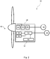
Figure 1 shows awind turbine 10 comprising atower 12 supporting anacelle 14 to which arotor 16 is mounted. Therotor 16 comprises a plurality ofwind turbine blades 18, wherein eachblade 18 of the plurality ofwind turbine blades 18 extends radially from acentral hub 20. In this example, therotor 16 comprises threeblades 18, although it will be apparent to those skilled in the art that other configurations are possible. - With reference also to
Figure 2 , which is a schematic illustration of thewind turbine 10 at a systems level, thewind turbine 10 further comprises agearbox 22 and apower generation system 24 including agenerator 26 and apower converter system 28. As is known, thegearbox 22 gears up the rotational speed of therotor 16 and drives thegenerator 26, which in turn feeds generated power to aconverter system 28. Usually such a system will be based on three-phase electrical power, although this is not essential. Other wind turbine designs are known, such as 'gearless' types, also known as 'direct drive', as well as 'belt drive' transmission types. - The
generator 26 andconverter system 28 may, as examples, be based on a full-scale converter (FSC) architecture or a doubly-fed induction generator (DFIG) architecture, although other architectures would be known to the skilled person. - In the illustrated embodiment, the power output of the
converter system 28 of thewind turbine 10 is transmitted to a load, which is shown here as anelectrical grid 30. The skilled person would be aware that different power conversion and transmission options exist. - The
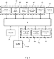
wind turbine 10 further comprises a control means 32 that is operable to monitor the operation of thewind turbine 10 and to issue commands thereto to achieve a set of control objectives. The control means 32 is shown inFigure 2 as a simplified, schematic overview of a plurality of control units and modules, and also inFigure 3 , as a more detailed example of how specific units and modules may be arranged in order to facilitate data exchange between them. - The control means 32 comprises a
processor 34 configured to execute instructions that are stored in and read from amemory module 36 and / or an external data store that forms part of anexternal network 38. Measurement data may also be stored in thememory module 36, and recalled in order to execute processes according to the instructions being carried out by theprocessor 34. - Instructions and data may also be received from external controllers or sensors that form part of the
external network 38, and recorded data and / or alerts may be issued over theexternal network 38 to be stored / displayed at an external source for analysis and remote monitoring. - In addition, the
processor 34 is in communication with a plurality ofsensors 40 that are disposed within thewind turbine 10. For example, as shown inFigure 3 , the plurality ofsensors 40 may comprise atower accelerometer 42, arotor speed sensor 44, a bladepitch angle sensor 46, a nacelleyaw angle sensor 48, and awind speed sensor 49. - The control means 32 of the
wind turbine 10 also includes at least onecontrol unit 50. - In the configuration shown in
Figure 3 , threecontrol units 50 are included, namely: (i) a blade pitchangle control unit 52 for altering the blade pitch angle of therotor blades 18; (ii) a nacelle yawangle control unit 54 for altering the yaw angle of thenacelle 14; and, (iii) aspeed control unit 56 that is used to alter the rotor speed of thewind turbine 10 using a brake, for example. In an alternative embodiment, the control means 32 includes a production controller (not shown), which controls the rotor speed of thewind turbine 10 through converter control and pitch control, depending on the specific control setup, thereby removing the need for a dedicatedspeed control unit 56. - It should be appreciated that the
wind turbine 10 would includemore control units 50, and thatFigure 3 is provided only to illustrate an example of a system architecture in which the invention may be implemented. - A principal function of the control means 32 is to control power generation of the
wind turbine 10 so that it optimises power production under current ambient wind conditions and in accordance with demanded power generation by a transmission grid operator. However, in addition to its main power control tasks, the control means 32 may be operable to perform a suite of safety and diagnostic monitoring functions and solutions. In the embodiments of the invention, one of these functions is to assess the conditions giving rise to unacceptable blade edgewise vibrations, and to control thewind turbine 10 accordingly. The identification of blade edgewise vibrations is important, as it may aid in preventing damage to thewind turbine 10 due to unwanted oscillation of therotor 16 during operation. Additionally, monitoring should be undertaken to ensure that dangerous levels of vibration are not reached. - Edgewise vibrations of rotor blades occur along the length of the blade in the edgewise direction, which is one of two main directions in which the blade principally vibrates and oscillates. The other main direction of oscillation is in a "flapwise" direction. Referring to
Figures 4 and5 , when considering arotor blade 18 having anoutboard blade section 60, indicated by dotted lines inFigure 4 , and acircular blade root 62, oscillations in the edgewise direction cause theblade 18 to move along anedgewise axis 64 which extends generally through the leading and trailingedges blade 18. Theedgewise axis 64 is therefore substantially perpendicular to thelongitudinal axis 69 of theblade 18. Similarly, oscillations in the flapwise direction cause the blade to move relative to aflapwise axis 70 which extends through the upper andlower surfaces blade 18 and is substantially perpendicular to both thelongitudinal axis 69 and theedgewise axis 64 of theblade 18. A blade may oscillate in both flapwise and edgewise directions simultaneously. - When the
rotor 16 is turning, oscillations of theblades 18 along their edgewise axes can cause movement of theblade 18 in the same plane as the plane of rotation of therotor 16. Since edgewise oscillation of theblades 18 excites therotor 16 with a force that is transverse to its longitudinal axis, in resonant conditions this may result in the rotational axis of the rotor shaft describing an erratic pattern of motion. This phenomenon is known as 'whirling'. - The seemingly complex pattern of motion of the
rotor 16 is the result of two circularly rotating force vectors that are generated by the combined oscillatory behaviour of theblades 18. A first force vector rotates in the same rotational direction as therotor 16 but at a higher frequency (progressive force vector) and a second force vector that rotates in a direction opposite to that of the rotor and at a lower frequency (regressive force vector). The result of the progressive and regressive force vectors is a force vector that traces an elliptical path, when viewed in a rotating reference frame aligned with therotor 16. - The phase difference between the edgewise oscillations of the blades determines whether whirling occurs in the same direction as the rotor rotation, which is generally known as forward whirl or 'forward whirling mode', or whether whirling occurs in a direction opposite to that of the rotor rotation, which is generally known as backward whirl or 'backward whirling mode'.
- As will be appreciated, whirling of the rotor shaft imparts lateral forces to the
nacelle 14 via therotor 16 and therefore causes it to sway from side to side. This motion may be detectable by monitoring the behaviour of thenacelle 14 or the upper portion of thetower 12, and motion at a whirling frequency above a certain level can be considered to be indicative of theblades 18 oscillating unacceptably in the edgewise direction. It is this movement that the inventor has appreciated can be used to identify blade edgewise vibrations and to take mitigating action. -
Figures 6 to 8 are flow diagrams of processes according to embodiments of the invention.Figures 6 and7 both show flowcharts ofprocesses Figure 8 is a flowchart of aprocess 300 for controlling awind turbine 10, based on identification of the whirling mode frequencies. These processes may be implemented using the system architectures outlined inFigures 2 and3 . - The
process 100 ofFigure 6 initiates atstep 102, and at thesecond step 104, the rotor speed is measured by therotor speed sensor 44. A time series of the rotor speed, measured over a predetermined measurement period by therotor speed sensor 44, is created and at the next step of theprocess 106, a low pass filter is applied to the rotor speed time series measurement. By applying a low pass filter, an average rotor speed signal is obtained. - From the average rotor speed, a rotational frequency is calculated 108. The process moves to the
next step 110, where, by using a predeterminededgewise frequency value 112 and the rotational frequency 108, the whirling mode frequencies can be mapped 110. Theedgewise frequency 112 is the frequency at which therotor blades 18 vibrate in the edgewise direction, and is a known parameter of therotor blades 18 that is stored and recalled from thememory module 36. Theedgewise frequency value 112 may be calculated using a number of techniques, for example it may be calculated based on structural models of the specific blade type used on thewind turbine 10 or it may be determined by way of subjecting that specific blade type to a testing procedure designed to identify the natural edgewise frequency (eigenfrequency) of the blade. - In one embodiment, the
mapping 110 of the edgewise frequency to forward and backward whirling mode frequencies is envisaged to be a subtraction and addition of the two component frequencies, i.e. the backward whirling mode frequency is calculated by subtracting the rotational frequency 108 from theedgewise frequency 112, and the forward whirling mode frequency is calculated by the addition of the rotational frequency 108 and theedgewise frequency 112. The mapping of higher order modes is also envisaged. - Following the
mapping step 110, whirling mode frequencies, which correspond to a forward whirling mode and a backward whirling mode, are obtained. These whirling mode frequencies are then stored 114, 116 in thememory module 36 for subsequent use, before the process terminates atstep 118. It is envisaged that the process repeats continually so as to re-calculate the whirling mode frequencies to ensure they are accurate. It will be appreciated by those skilled in the art that the various whirling mode frequencies of thewind turbine 10 could also be determined during the design of theblade 18 and / or modelling of therotor 16. - Once the whirling mode frequencies have been calculated, a
further process 200, as illustrated inFigure 7 , may be used to calibrate the determined whirling mode frequencies, as will now be described. - The
process 200 initiates atstep 202, which may be when thewind turbine 10 has been started but prior to reaching a power generating state or during a production state. - Initially, the
process 200 proceeds along two branches simultaneously. At afirst branch 204, a whirling mode frequency is received 206. The whirling mode frequency is calculated according to theprocess 100 shown inFigure 6 , and recalled from thememory module 36 by theprocessor 34. In another embodiment of the invention, the whirling mode frequency may be a parameter stored within thememory module 36 that has been calculated or predetermined in some other way, for example determined during the design of theblade 18 and / or modelling of the rotor system. - It will be appreciated that both of the whirling mode frequencies calculated using the
process 100 or otherwise determined may be used in theprocess 200 by implementing two of theprocesses 200 simultaneously. However, for ease of understanding the following discussion will be based on analysing data relating to a single whirling mode frequency. - Having received the whirling mode frequency, the
processor 34 implements, atstep 208, a band-pass filter having a centre frequency set as equal to the whirling mode frequency. A bandwidth for the filter may be a set bandwidth for each whirling mode frequency, or it may vary according to the frequency and / or speed of the rotor. It is envisaged, however, that the bandwidth of the filter would be in the range 0.1Hz to 0.5Hz, although it is possible that smaller or greater bandwidths could be used depending on the intended outcome. - In a second
initial branch 210 of theprocess 200, atstep 212, a signal indicative of the edgewise vibrational movement of theblades 18 is measured. The signal may include a component of tower acceleration in a direction parallel to the rotor plane, i.e. transverse to a longitudinal axis of the nacelle. The tower acceleration is measured using a sensor, such as theaccelerometer 42, either mounted within thenacelle 14 or located towards the top of thetower 12. Theprocessor 34 receives an acceleration measurement time series over a respective period of time. The period over which measurements are made may vary according to the speed of therotor 16 or may be set at a single value. Measurements are made continuously by the accelerometer using a series of overlapping sampling windows, also referred to as a 'rolling average' or other methods. A typical window length would be between 1 and 5 seconds, with a sampling frequency of at least 10Hz. It will be appreciated by those skilled in the art that other averaging techniques may be used such as an exponential averaging technique. - Alternatively, the signal measured at
step 212 could be obtained from a sensor (not shown) suitable for measuring the edgewise vibrational movement of theblades 18, such as an optical sensor, an accelerometer, a gyrosensor, a load sensor or a strain sensor placed in the root of each of theblades 18 or at other positions in theblades 18. - The signal measured at
step 212 is then filtered, atstep 214, using the band-pass filter. Some operational vibration and other frequency content is filtered out by the band-pass filter, leaving a signal that is substantially composed of vibration in the region of the whirling mode frequency that is caused by the edgewise vibrations of theblades 18. In this way, the process determines, obtains, or calculates a frequency spectrum in the time domain of the measured edgewise vibrational movement of theblades 18 in the proximity of the determined whirling mode frequency. In effect, this process narrows the scope of the measured acceleration or other signals indicating the edgewise vibrational movement of theblades 18 to consider only the region of the whirling mode frequency. - At
step 216, a central frequency is determined from the frequency spectrum obtained instep 214 as the frequency component with the largest peak in the frequency spectrum or with the highest power spectral density. - The central frequency signal is then compared, at
step 218, to the whirling mode frequency obtained fromprocess 100 or otherwise determined. - If the central frequency is the same as the determined whirling mode frequency, the
process 200 progresses to step 224, where theprocess 200 terminates. However, if the central frequency differs from the determined whirling mode frequency, theprocess 200 progresses to step 222 where the determined whirling mode frequency is adjusted, for example, so as to be the same as the central frequency. Theprocess 200 then progresses to step 223 where the adjusted whirling mode frequency is stored in thememory module 36 for subsequent use, before theprocess 200 terminates atstep 224. It is envisaged that theprocess 200 could repeat continually to adjust the determined whirling mode frequency to ensure its accuracy. - Once the whirling mode frequency has been determined using
process 100 and / orprocess 200, afurther process 300, as illustrated inFigure 8 , is used to decide how thewind turbine 10 should be controlled in view of the determined whirling mode frequency. - The
process 300 initiates atstep 302, which can be any time during which thewind turbine 10 is operating, and in thesecond step 304, the whirling mode frequency is received having been recalled from thememory module 36 by theprocessor 34. A rotational frequency is then calculated at thenext step 306 of theprocess 300 based on the rotational speed of therotor 16. - A threshold value for the whirling mode frequency, based on the rotational frequency, is then determined at
step 308. The threshold value defines a buffer zone extending from the rotational frequency, and is used during the control of thewind turbine 10 to prevent the whirling mode frequency and the rotational frequency from converging to the extent that leads to resonant conditions giving rise to excessive edgewise vibrations of theblades 18. The threshold value can be calculated as a function of the determined rotational frequency. For example, the threshold value may be calculated as a percentage of the rotational frequency. That is, if the determined rotational frequency is 2Hz, the threshold value, calculated as 10% of the determined rotational frequency, would be 2.2Hz. In this example, the threshold value defines a buffer zone extending from the rotational frequency having a width of 0.2Hz. Alternatively, the threshold value may be determined based on a numerical simulation of thewind turbine 10. In this case, the operation of thewind turbine 10 is simulated to identify the rotor speeds that give rise to excessive edgewise vibrational movement of theblades 18. Once identified, the rotor speeds are converted to the frequency domain to be used as a baseline for establishing the threshold value. That is, the threshold value may be the same as or, alternatively, determined as a function of the rotational frequencies that correspond to the rotor speeds identified in the numerical simulation. - The whirling mode frequency is then compared, at
step 314, to the threshold value obtained atstep 308. If the whirling mode frequency substantially equals or is lower than the threshold value, theprocess 300 progresses to step 316 where the rotor speed is reduced. Reducing the rotor speed results in a corresponding reduction in the rotational frequency to maintain the buffer zone between the two frequencies and prevent resonant conditions from developing. In one embodiment, the rotor speed is reduced until the whirling mode frequency is greater than the threshold value. In the case where the whirling mode frequency relates to a backward whirl, reducing the rotational frequency produces a corresponding increase in the whirling mode frequency, causing a divergence of the two frequencies. This divergent movement of the frequencies is beneficial when re-establishing the buffer zone as it allows the reduction in the rotational frequency, and so the rotor speed, to be minimised. On the other hand, where the whirling mode frequency relates to a forward whirl, reducing the rotational frequency produces a corresponding decrease in the whirling mode frequency. However, the respective decreases in the whirling mode frequency and the rotational frequency are not proportional, and so a reduction in the rotational frequency still has the effect of causing a divergence of the two frequencies. - If, at
step 314, it is determined that the whirling mode frequency is greater than the threshold value, theprocess 300 progresses to step 318 where no action is taken and the rotor speed is maintained. - The
process 300 terminates atstep 320 following the execution ofsteps process 300 could repeat continually to control the rotor speed in accordance with the threshold value and its relationship with the whirling mode frequency. In that case, theprocess 300 could be continued from theinitial step 302 or fromstep 314. - As mentioned above, the threshold value sets a limit, based on the rotational frequency, which defines a buffer zone extending from the rotational frequency. Resonant conditions can develop if the whirling mode frequency is within the buffer zone. That is, resonant conditions, which can lead to excessive edgewise vibrations of the
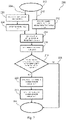
blades 18, can develop if the whirling mode frequency substantially equals or is lower than the limit defined by the threshold value.Figure 9 shows aprocess 400 for altering the threshold value determined inprocess 300 according to whether or not resonant conditions are observed when the whirling mode frequency substantially equals or is lower than the threshold value. - The
process 400 initiates atstep 402, which could be after theprocess 300 has been executed or, in the event that theprocess 300 is repeated continuously, betweenconsecutive processes 300. Atstep 404, a signal indicative of an edgewise vibrational movement of theblades 18 is measured. This signal is the same as the signal measured atstep 212 of theprocess 200. Accordingly, the signal can relate to an indirect measurement of the movement, such as measuring a component of tower acceleration, or a direct measurement, such as a measurement from a sensor placed in the root of each of theblades 18 or at other positions in theblades 18. - The whirling mode frequency is then compared, at
step 406, to the threshold value. If it is determined that the whirling mode frequency is greater than the threshold value, theprocess 400 moves to step 408 where the signal is analysed to determine if theblades 18 are experiencing an edgewise vibrational movement. If the presence of an edgewise vibrational movement is determined, theprocess 400 moves to step 412 where the threshold value is increased with respect to the rotational frequency, thereby increasing the buffer zone extending from the rotational frequency. Conversely, if, atstep 408, the presence of an edgewise vibrational movement is not observed, theprocess 400 proceeds to step 414 where the current threshold value is maintained. - Turning back to step 406, if it is determined that the whirling mode frequency substantially equals or is lower than the threshold value, the
process 400 moves to step 410 where, again, the signal is analysed to determine if theblades 18 are experiencing an edgewise vibrational movement. If the presence of an edgewise vibrational movement is established, theprocess 400 moves to step 414 where the threshold value is maintained. However, if, atstep 410, the presence of an edgewise vibrational movement is not observed, theprocess 400 proceeds to step 416 where the current threshold value is decreased with respect to the rotational frequency, resulting in a corresponding decrease in the buffer zone between the rotational frequency and the whirling mode frequency. Minimising the size of the buffer zone is beneficial as it avoids unnecessary reductions in the rotational frequency, and so the rotational speed of therotor 16, when avoiding the onset of resonant conditions. Specifically, a reduction in the speed of therotor 16 is, in some instances, accompanied by a reduction in the power outputted from thegenerator 26. This is done to avoid damaging thegearbox 22 due to the increase in the torque that would be required if the power outputted from thegenerator 26 remained the same while the speed of therotor 16 is decreased. Accordingly, it is preferable to keep the speed of therotor 16 as high is possible to avoid power losses and any associated damage to thegearbox 22. - The
process 400 terminates atstep 418 following the execution ofsteps -
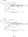
Figure 10 showsgraphs process 300.Graphs rotational frequency 502 and the whirlingmode frequency 504 over a wind speed range. Specifically, the whirlingmode frequency 504 shown in this example is illustrative of a 3P rotational frequency and backward whirling mode, and although other modes, such as a 6P rotational frequency and backward whirling mode, behave in a similar manner, there may exist whirling modes that behave differently with respect to wind speed. Therefore, the examples shown in thegraphs buffer zone 506, which is a function of therotational frequency 502, extends from therotational frequency 502 and has an upper limit defined by thethreshold value 508. - Turning to graph 500, it can be seen that, with respect to wind speed, the
rotational frequency 502 increases up to a maximum, when thewind turbine 10 is operating in a full load operation mode, and the whirlingmode frequency 504 decreases. That is, therotational frequency 502 and the whirlingmode frequency 504 tend to converge with increasing wind speed. In this example, the whirlingmode frequency 504 falls below thethreshold value 504 and enters thebuffer zone 506 at the high end of the wind speed range. If this situation is left unchecked, the proximity of therotational frequency 502 and the whirlingmode frequency 504 within thebuffer zone 506 could give rise to resonant conditions, causing theblades 18 to undergo excessive edgewise vibrational movements. - The
process 300 addresses this situation by decreasing the speed of therotor 16, and so therotational frequency 502, as illustrated ingraph 501. This causes a corresponding reduction in thethreshold value 508 and an increase in thewhirling mode frequency 504, which causes the twofrequencies frequencies buffer zone 506, preventing the onset resonant conditions. - In general, the speed of the
rotor 16 may be controlled in any appropriate way. The adjustment of the speed of therotor 16 to a given value may be obtained by adjusting the speed in accordance with a rotor speed set point. However, the speed of therotor 16 may also be adjusted by other means, such as use of a rotor torque set point or output power set point. It will be appreciated by those skilled in the art that the invention has been described by way of example only, and that a variety of alternative approaches may be adopted without departing from the scope of the invention, as defined by the appended claims.
Claims (14)
- A method of controlling a wind turbine for the avoidance of edgewise vibrations, the method comprising:determining a whirling mode frequency of a rotor blade of the wind turbine;determining a rotational frequency of the rotor blade corresponding to the speed of the rotor blade;characterized by determining a frequency threshold value for the whirling mode frequency based on the rotational frequency; and,reducing the speed of the rotor blade if the whirling mode frequency substantially equals or is less than the frequency threshold value.
- A method according to claim 1, wherein the frequency threshold value is determined as a function of the rotational frequency and ambient wind conditions.
- A method according to claim 1 or 2, further comprising reducing the speed of the rotor blade until the whirling mode frequency is greater than the frequency threshold value.
- A method according to any preceding claim, wherein the whirling mode frequency is one or more of a forward whirling mode or a backward whirling mode.
- A method according to any preceding claim, wherein the whirling mode frequency is determined as function of the rotational frequency and a predetermined edgewise vibration frequency of the rotor blade.
- A method according to any preceding claim, further comprising:measuring a signal indicative of a vibrational movement of the rotor blade;determining a frequency spectrum of the measured signal in the proximity of the whirling mode frequency;obtaining a central frequency from the frequency spectrum; and,adjusting the whirling mode frequency with respect to the central frequency.
- A method according to claim 6, wherein the whirling mode frequency is adjusted to equal the central frequency.
- A method according to any one of claims 1 to 5, further comprising:measuring a signal indicative of a vibrational movement of the rotor blade; and,increasing the frequency threshold value relative to the rotational frequency if the signal indicates that the rotor blade is moving; or,decreasing the frequency threshold value relative to the rotational frequency if the signal indicates that the rotor blade is not moving.
- A method according to any one of claims 6 to 8, wherein the signal is indicative of an edgewise vibration of the rotor blade.
- A method according to any one of claims 6 to 8, wherein the signal is an acceleration signal indicative of the movement of the tower top of the wind turbine.
- A method according to any preceding claim, wherein the wind turbine is operated in full load operation mode.
- A controller for a wind turbine control system comprising a processor and a memory module, wherein the memory module comprises a set of program code instructions which when executed by the processor implement a method according to any one of claims 1 to 11.
- A wind turbine comprising the controller of claim 12.
- A computer program product downloadable from a communication network and / or stored on a machine readable medium comprising program code instructions which, when the program is executed by a computer, cause the computer to implement a method according to any one of claims 1 to 11.
Applications Claiming Priority (2)
| Application Number | Priority Date | Filing Date | Title |
|---|---|---|---|
| DKPA201870082 | 2018-02-09 | ||
| PCT/DK2019/050042 WO2019154470A1 (en) | 2018-02-09 | 2019-02-04 | Method and system for controlling a wind turbine to manage edgewise blade vibrations |
Publications (2)
| Publication Number | Publication Date |
|---|---|
| EP3749850A1 EP3749850A1 (en) | 2020-12-16 |
| EP3749850B1 true EP3749850B1 (en) | 2022-11-30 |
Family
ID=65363025
Family Applications (1)
| Application Number | Title | Priority Date | Filing Date |
|---|---|---|---|
| EP19704186.6A Active EP3749850B1 (en) | 2018-02-09 | 2019-02-04 | Method and system for controlling a wind turbine to manage edgewise blade vibrations |
Country Status (5)
| Country | Link |
|---|---|
| US (1) | US11525431B2 (en) |
| EP (1) | EP3749850B1 (en) |
| CN (1) | CN111836957B (en) |
| ES (1) | ES2932881T3 (en) |
| WO (1) | WO2019154470A1 (en) |
Families Citing this family (2)
| Publication number | Priority date | Publication date | Assignee | Title |
|---|---|---|---|---|
| US11525431B2 (en) | 2018-02-09 | 2022-12-13 | Vestas Wind Systems A/S | Method and system for controlling a wind turbine to manage edgewise blade vibrations |
| CN113358307B (en) * | 2021-06-02 | 2023-03-21 | 西安西热节能技术有限公司 | Judgment method for determining rotor whirling direction according to shaft vibration signal |
Family Cites Families (12)
| Publication number | Priority date | Publication date | Assignee | Title |
|---|---|---|---|---|
| DE10016912C1 (en) | 2000-04-05 | 2001-12-13 | Aerodyn Eng Gmbh | Operation of offshore wind turbines dependent on the natural frequency of the tower |
| DK179081B1 (en) * | 2007-06-25 | 2017-10-16 | Siemens Wind Power As | Monitoring of a wind turbine's wing frequencies |
| CN101999039B (en) * | 2007-11-30 | 2012-12-19 | 维斯塔斯风力系统有限公司 | A wind turbine, a method for controlling a wind turbine and use thereof |
| EP2531724B1 (en) * | 2010-04-12 | 2018-12-26 | Siemens Aktiengesellschaft | Method and system for determining a mass change on a rotating blade of a wind turbine |
| US20120257967A1 (en) | 2011-04-05 | 2012-10-11 | Per Egedal | Method and controller for generating a blade pitch angle control signal and wind turbine comprising the controller |
| US9803621B2 (en) * | 2012-06-08 | 2017-10-31 | Vestas Wind Systems A/S | Wind turbine control |
| EP3080444B1 (en) * | 2013-12-09 | 2022-03-30 | General Electric Company | System and method for reducing oscillation loads of wind turbine |
| DK201470481A1 (en) | 2014-08-13 | 2015-08-17 | Vestas Wind Sys As | Improvements relating to wind turbine operation |
| DK3384154T3 (en) * | 2015-12-04 | 2021-01-25 | Envision Energy Denmark Aps | A wind turbine and a method of controlling a wind turbine to reduce angular oscillations |
| US10738762B2 (en) * | 2016-04-08 | 2020-08-11 | Vestas Wind Systems A/S | Method and system for controlling a wind turbine to manage edgewise blade vibrations |
| CN106224162B (en) * | 2016-07-29 | 2018-10-16 | 电子科技大学 | The load model method for building up and load controlled method of Wind turbines |
| US11525431B2 (en) | 2018-02-09 | 2022-12-13 | Vestas Wind Systems A/S | Method and system for controlling a wind turbine to manage edgewise blade vibrations |
-
2019
- 2019-02-04 US US16/968,860 patent/US11525431B2/en active Active
- 2019-02-04 CN CN201980018339.5A patent/CN111836957B/en active Active
- 2019-02-04 EP EP19704186.6A patent/EP3749850B1/en active Active
- 2019-02-04 ES ES19704186T patent/ES2932881T3/en active Active
- 2019-02-04 WO PCT/DK2019/050042 patent/WO2019154470A1/en unknown
Also Published As
| Publication number | Publication date |
|---|---|
| ES2932881T3 (en) | 2023-01-27 |
| US11525431B2 (en) | 2022-12-13 |
| WO2019154470A1 (en) | 2019-08-15 |
| CN111836957A (en) | 2020-10-27 |
| US20210010457A1 (en) | 2021-01-14 |
| EP3749850A1 (en) | 2020-12-16 |
| CN111836957B (en) | 2023-09-26 |
Similar Documents
| Publication | Publication Date | Title |
|---|---|---|
| EP3440348B1 (en) | Method and system for controlling a wind turbine to manage edgewise blade vibrations | |
| EP3707375B1 (en) | Method and system for controlling a wind turbine to manage edgewise blade vibrations | |
| US8803351B2 (en) | Control method for a wind turbine | |
| CN107850050B (en) | Wind turbine and method of operating a wind turbine with reduced edgewise vibrations | |
| US10107261B2 (en) | System and method for reducing oscillation loads of wind turbine | |
| CN110446853B (en) | System and method for managing torsional oscillations of a wind turbine tower | |
| US11572865B2 (en) | Method and system for controlling a wind turbine to reduce nacelle vibration | |
| CN108026895B (en) | The operation method of wind turbine and the wind turbine with red band | |
| EP3056726B1 (en) | System and method for operating a wind turbine based on rotor blade margin | |
| EP3794230B1 (en) | Method and system for controlling a wind turbine to reduce nacelle vibration | |
| EP3749850B1 (en) | Method and system for controlling a wind turbine to manage edgewise blade vibrations | |
| WO2023088432A1 (en) | Controller for a wind turbine | |
| KR20230129930A (en) | Vibrations in wind turbines | |
| CN113795666A (en) | Wind driven generator and method for operating same |
Legal Events
| Date | Code | Title | Description |
|---|---|---|---|
| STAA | Information on the status of an ep patent application or granted ep patent |
Free format text: STATUS: UNKNOWN |
|
| STAA | Information on the status of an ep patent application or granted ep patent |
Free format text: STATUS: THE INTERNATIONAL PUBLICATION HAS BEEN MADE |
|
| PUAI | Public reference made under article 153(3) epc to a published international application that has entered the european phase |
Free format text: ORIGINAL CODE: 0009012 |
|
| STAA | Information on the status of an ep patent application or granted ep patent |
Free format text: STATUS: REQUEST FOR EXAMINATION WAS MADE |
|
| 17P | Request for examination filed |
Effective date: 20200804 |
|
| AK | Designated contracting states |
Kind code of ref document: A1 Designated state(s): AL AT BE BG CH CY CZ DE DK EE ES FI FR GB GR HR HU IE IS IT LI LT LU LV MC MK MT NL NO PL PT RO RS SE SI SK SM TR |
|
| AX | Request for extension of the european patent |
Extension state: BA ME |
|
| DAV | Request for validation of the european patent (deleted) | ||
| DAX | Request for extension of the european patent (deleted) | ||
| GRAP | Despatch of communication of intention to grant a patent |
Free format text: ORIGINAL CODE: EPIDOSNIGR1 |
|
| STAA | Information on the status of an ep patent application or granted ep patent |
Free format text: STATUS: GRANT OF PATENT IS INTENDED |
|
| INTG | Intention to grant announced |
Effective date: 20220915 |
|
| GRAS | Grant fee paid |
Free format text: ORIGINAL CODE: EPIDOSNIGR3 |
|
| GRAA | (expected) grant |
Free format text: ORIGINAL CODE: 0009210 |
|
| STAA | Information on the status of an ep patent application or granted ep patent |
Free format text: STATUS: THE PATENT HAS BEEN GRANTED |
|
| AK | Designated contracting states |
Kind code of ref document: B1 Designated state(s): AL AT BE BG CH CY CZ DE DK EE ES FI FR GB GR HR HU IE IS IT LI LT LU LV MC MK MT NL NO PL PT RO RS SE SI SK SM TR |
|
| REG | Reference to a national code |
Ref country code: CH Ref legal event code: EP Ref country code: GB Ref legal event code: FG4D |
|
| REG | Reference to a national code |
Ref country code: AT Ref legal event code: REF Ref document number: 1534880 Country of ref document: AT Kind code of ref document: T Effective date: 20221215 Ref country code: DE Ref legal event code: R096 Ref document number: 602019022512 Country of ref document: DE |
|
| REG | Reference to a national code |
Ref country code: IE Ref legal event code: FG4D |
|
| REG | Reference to a national code |
Ref country code: ES Ref legal event code: FG2A Ref document number: 2932881 Country of ref document: ES Kind code of ref document: T3 Effective date: 20230127 |
|
| REG | Reference to a national code |
Ref country code: LT Ref legal event code: MG9D |
|
| REG | Reference to a national code |
Ref country code: NL Ref legal event code: MP Effective date: 20221130 |
|
| PG25 | Lapsed in a contracting state [announced via postgrant information from national office to epo] |
Ref country code: SE Free format text: LAPSE BECAUSE OF FAILURE TO SUBMIT A TRANSLATION OF THE DESCRIPTION OR TO PAY THE FEE WITHIN THE PRESCRIBED TIME-LIMIT Effective date: 20221130 Ref country code: PT Free format text: LAPSE BECAUSE OF FAILURE TO SUBMIT A TRANSLATION OF THE DESCRIPTION OR TO PAY THE FEE WITHIN THE PRESCRIBED TIME-LIMIT Effective date: 20230331 Ref country code: NO Free format text: LAPSE BECAUSE OF FAILURE TO SUBMIT A TRANSLATION OF THE DESCRIPTION OR TO PAY THE FEE WITHIN THE PRESCRIBED TIME-LIMIT Effective date: 20230228 Ref country code: LT Free format text: LAPSE BECAUSE OF FAILURE TO SUBMIT A TRANSLATION OF THE DESCRIPTION OR TO PAY THE FEE WITHIN THE PRESCRIBED TIME-LIMIT Effective date: 20221130 Ref country code: FI Free format text: LAPSE BECAUSE OF FAILURE TO SUBMIT A TRANSLATION OF THE DESCRIPTION OR TO PAY THE FEE WITHIN THE PRESCRIBED TIME-LIMIT Effective date: 20221130 |
|
| PGFP | Annual fee paid to national office [announced via postgrant information from national office to epo] |
Ref country code: FR Payment date: 20230223 Year of fee payment: 5 Ref country code: ES Payment date: 20230323 Year of fee payment: 5 |
|
| REG | Reference to a national code |
Ref country code: AT Ref legal event code: MK05 Ref document number: 1534880 Country of ref document: AT Kind code of ref document: T Effective date: 20221130 |
|
| PG25 | Lapsed in a contracting state [announced via postgrant information from national office to epo] |
Ref country code: RS Free format text: LAPSE BECAUSE OF FAILURE TO SUBMIT A TRANSLATION OF THE DESCRIPTION OR TO PAY THE FEE WITHIN THE PRESCRIBED TIME-LIMIT Effective date: 20221130 Ref country code: PL Free format text: LAPSE BECAUSE OF FAILURE TO SUBMIT A TRANSLATION OF THE DESCRIPTION OR TO PAY THE FEE WITHIN THE PRESCRIBED TIME-LIMIT Effective date: 20221130 Ref country code: LV Free format text: LAPSE BECAUSE OF FAILURE TO SUBMIT A TRANSLATION OF THE DESCRIPTION OR TO PAY THE FEE WITHIN THE PRESCRIBED TIME-LIMIT Effective date: 20221130 Ref country code: IS Free format text: LAPSE BECAUSE OF FAILURE TO SUBMIT A TRANSLATION OF THE DESCRIPTION OR TO PAY THE FEE WITHIN THE PRESCRIBED TIME-LIMIT Effective date: 20230330 Ref country code: HR Free format text: LAPSE BECAUSE OF FAILURE TO SUBMIT A TRANSLATION OF THE DESCRIPTION OR TO PAY THE FEE WITHIN THE PRESCRIBED TIME-LIMIT Effective date: 20221130 Ref country code: GR Free format text: LAPSE BECAUSE OF FAILURE TO SUBMIT A TRANSLATION OF THE DESCRIPTION OR TO PAY THE FEE WITHIN THE PRESCRIBED TIME-LIMIT Effective date: 20230301 |
|
| PGFP | Annual fee paid to national office [announced via postgrant information from national office to epo] |
Ref country code: GB Payment date: 20230214 Year of fee payment: 5 Ref country code: DE Payment date: 20230227 Year of fee payment: 5 |
|
| P01 | Opt-out of the competence of the unified patent court (upc) registered |
Effective date: 20230521 |
|
| PG25 | Lapsed in a contracting state [announced via postgrant information from national office to epo] |
Ref country code: NL Free format text: LAPSE BECAUSE OF FAILURE TO SUBMIT A TRANSLATION OF THE DESCRIPTION OR TO PAY THE FEE WITHIN THE PRESCRIBED TIME-LIMIT Effective date: 20221130 |
|
| PG25 | Lapsed in a contracting state [announced via postgrant information from national office to epo] |
Ref country code: SM Free format text: LAPSE BECAUSE OF FAILURE TO SUBMIT A TRANSLATION OF THE DESCRIPTION OR TO PAY THE FEE WITHIN THE PRESCRIBED TIME-LIMIT Effective date: 20221130 Ref country code: RO Free format text: LAPSE BECAUSE OF FAILURE TO SUBMIT A TRANSLATION OF THE DESCRIPTION OR TO PAY THE FEE WITHIN THE PRESCRIBED TIME-LIMIT Effective date: 20221130 Ref country code: EE Free format text: LAPSE BECAUSE OF FAILURE TO SUBMIT A TRANSLATION OF THE DESCRIPTION OR TO PAY THE FEE WITHIN THE PRESCRIBED TIME-LIMIT Effective date: 20221130 Ref country code: DK Free format text: LAPSE BECAUSE OF FAILURE TO SUBMIT A TRANSLATION OF THE DESCRIPTION OR TO PAY THE FEE WITHIN THE PRESCRIBED TIME-LIMIT Effective date: 20221130 Ref country code: CZ Free format text: LAPSE BECAUSE OF FAILURE TO SUBMIT A TRANSLATION OF THE DESCRIPTION OR TO PAY THE FEE WITHIN THE PRESCRIBED TIME-LIMIT Effective date: 20221130 Ref country code: AT Free format text: LAPSE BECAUSE OF FAILURE TO SUBMIT A TRANSLATION OF THE DESCRIPTION OR TO PAY THE FEE WITHIN THE PRESCRIBED TIME-LIMIT Effective date: 20221130 |
|
| PG25 | Lapsed in a contracting state [announced via postgrant information from national office to epo] |
Ref country code: SK Free format text: LAPSE BECAUSE OF FAILURE TO SUBMIT A TRANSLATION OF THE DESCRIPTION OR TO PAY THE FEE WITHIN THE PRESCRIBED TIME-LIMIT Effective date: 20221130 Ref country code: AL Free format text: LAPSE BECAUSE OF FAILURE TO SUBMIT A TRANSLATION OF THE DESCRIPTION OR TO PAY THE FEE WITHIN THE PRESCRIBED TIME-LIMIT Effective date: 20221130 |
|
| REG | Reference to a national code |
Ref country code: DE Ref legal event code: R097 Ref document number: 602019022512 Country of ref document: DE |
|
| PG25 | Lapsed in a contracting state [announced via postgrant information from national office to epo] |
Ref country code: MC Free format text: LAPSE BECAUSE OF FAILURE TO SUBMIT A TRANSLATION OF THE DESCRIPTION OR TO PAY THE FEE WITHIN THE PRESCRIBED TIME-LIMIT Effective date: 20221130 |
|
| REG | Reference to a national code |
Ref country code: CH Ref legal event code: PL |
|
| PLBE | No opposition filed within time limit |
Free format text: ORIGINAL CODE: 0009261 |
|
| STAA | Information on the status of an ep patent application or granted ep patent |
Free format text: STATUS: NO OPPOSITION FILED WITHIN TIME LIMIT |
|
| REG | Reference to a national code |
Ref country code: BE Ref legal event code: MM Effective date: 20230228 |
|
| PG25 | Lapsed in a contracting state [announced via postgrant information from national office to epo] |
Ref country code: LU Free format text: LAPSE BECAUSE OF NON-PAYMENT OF DUE FEES Effective date: 20230204 Ref country code: LI Free format text: LAPSE BECAUSE OF NON-PAYMENT OF DUE FEES Effective date: 20230228 Ref country code: CH Free format text: LAPSE BECAUSE OF NON-PAYMENT OF DUE FEES Effective date: 20230228 |
|
| 26N | No opposition filed |
Effective date: 20230831 |
|
| PG25 | Lapsed in a contracting state [announced via postgrant information from national office to epo] |
Ref country code: SI Free format text: LAPSE BECAUSE OF FAILURE TO SUBMIT A TRANSLATION OF THE DESCRIPTION OR TO PAY THE FEE WITHIN THE PRESCRIBED TIME-LIMIT Effective date: 20221130 |
|
| REG | Reference to a national code |
Ref country code: IE Ref legal event code: MM4A |
|
| PG25 | Lapsed in a contracting state [announced via postgrant information from national office to epo] |
Ref country code: IE Free format text: LAPSE BECAUSE OF NON-PAYMENT OF DUE FEES Effective date: 20230204 |
|
| PG25 | Lapsed in a contracting state [announced via postgrant information from national office to epo] |
Ref country code: BE Free format text: LAPSE BECAUSE OF NON-PAYMENT OF DUE FEES Effective date: 20230228 |
|
| PGFP | Annual fee paid to national office [announced via postgrant information from national office to epo] |
Ref country code: ES Payment date: 20240308 Year of fee payment: 6 |