EP3749846B1 - Système d'injection de solution aqueuse pour véhicule - Google Patents
Système d'injection de solution aqueuse pour véhicule Download PDFInfo
- Publication number
- EP3749846B1 EP3749846B1 EP19705129.5A EP19705129A EP3749846B1 EP 3749846 B1 EP3749846 B1 EP 3749846B1 EP 19705129 A EP19705129 A EP 19705129A EP 3749846 B1 EP3749846 B1 EP 3749846B1
- Authority
- EP
- European Patent Office
- Prior art keywords
- metal
- aqueous solution
- injection system
- injection
- fitting
- Prior art date
- Legal status (The legal status is an assumption and is not a legal conclusion. Google has not performed a legal analysis and makes no representation as to the accuracy of the status listed.)
- Active
Links
Images

Classifications
-
- F—MECHANICAL ENGINEERING; LIGHTING; HEATING; WEAPONS; BLASTING
- F02—COMBUSTION ENGINES; HOT-GAS OR COMBUSTION-PRODUCT ENGINE PLANTS
- F02M—SUPPLYING COMBUSTION ENGINES IN GENERAL WITH COMBUSTIBLE MIXTURES OR CONSTITUENTS THEREOF
- F02M25/00—Engine-pertinent apparatus for adding non-fuel substances or small quantities of secondary fuel to combustion-air, main fuel or fuel-air mixture
- F02M25/022—Adding fuel and water emulsion, water or steam
- F02M25/0221—Details of the water supply system, e.g. pumps or arrangement of valves
- F02M25/0224—Water treatment or cleaning
-
- C—CHEMISTRY; METALLURGY
- C02—TREATMENT OF WATER, WASTE WATER, SEWAGE, OR SLUDGE
- C02F—TREATMENT OF WATER, WASTE WATER, SEWAGE, OR SLUDGE
- C02F1/00—Treatment of water, waste water, or sewage
- C02F1/50—Treatment of water, waste water, or sewage by addition or application of a germicide or by oligodynamic treatment
- C02F1/505—Treatment of water, waste water, or sewage by addition or application of a germicide or by oligodynamic treatment by oligodynamic treatment
-
- F—MECHANICAL ENGINEERING; LIGHTING; HEATING; WEAPONS; BLASTING
- F02—COMBUSTION ENGINES; HOT-GAS OR COMBUSTION-PRODUCT ENGINE PLANTS
- F02M—SUPPLYING COMBUSTION ENGINES IN GENERAL WITH COMBUSTIBLE MIXTURES OR CONSTITUENTS THEREOF
- F02M25/00—Engine-pertinent apparatus for adding non-fuel substances or small quantities of secondary fuel to combustion-air, main fuel or fuel-air mixture
- F02M25/022—Adding fuel and water emulsion, water or steam
- F02M25/025—Adding water
-
- A—HUMAN NECESSITIES
- A61—MEDICAL OR VETERINARY SCIENCE; HYGIENE
- A61L—METHODS OR APPARATUS FOR STERILISING MATERIALS OR OBJECTS IN GENERAL; DISINFECTION, STERILISATION OR DEODORISATION OF AIR; CHEMICAL ASPECTS OF BANDAGES, DRESSINGS, ABSORBENT PADS OR SURGICAL ARTICLES; MATERIALS FOR BANDAGES, DRESSINGS, ABSORBENT PADS OR SURGICAL ARTICLES
- A61L2/00—Disinfection or sterilisation of materials or objects, in general; Accessories therefor
- A61L2/16—Disinfection or sterilisation of materials or objects, in general; Accessories therefor using chemical substances
- A61L2/23—Solid materials, e.g. granules, powders, blocks or tablets
- A61L2/238—Metals or alloys, e.g. oligodynamic metals
-
- Y—GENERAL TAGGING OF NEW TECHNOLOGICAL DEVELOPMENTS; GENERAL TAGGING OF CROSS-SECTIONAL TECHNOLOGIES SPANNING OVER SEVERAL SECTIONS OF THE IPC; TECHNICAL SUBJECTS COVERED BY FORMER USPC CROSS-REFERENCE ART COLLECTIONS [XRACs] AND DIGESTS
- Y02—TECHNOLOGIES OR APPLICATIONS FOR MITIGATION OR ADAPTATION AGAINST CLIMATE CHANGE
- Y02T—CLIMATE CHANGE MITIGATION TECHNOLOGIES RELATED TO TRANSPORTATION
- Y02T10/00—Road transport of goods or passengers
- Y02T10/10—Internal combustion engine [ICE] based vehicles
- Y02T10/12—Improving ICE efficiencies
Definitions
- the invention relates to aqueous solution injection systems for vehicles.
- Vehicle water injection systems typically include a water tank, a pump, and an injection line leading to an ejector from which water is ejected. After the water injection system has ejected water via the ejector, the water remaining in the injection line is purged and returned to the tank. However, at least some of this water has been in contact with air that has entered the injection line after ejection. This air is particularly likely to contain organic compounds or microorganisms such as bacteria. There is a risk that the microorganisms thus introduced will proliferate, which is not desirable. Indeed, certain microorganisms such as bacteria, fungi or algae are known to be able to adhere to a surface and, from there, proliferate and secrete an adhesive and protective matrix thus forming a biofilm.
- the proliferation of microorganisms and the formation of a biofilm are likely to reduce at least partially the internal space of a pipeline. This reduction can be the cause of malfunctions of the system by influencing in particular the pressure and the flow rate with which a liquid flows in the pipeline.
- the proliferation of microorganisms present in the biofilm can be such that the biofilm can end up completely obstructing the pipeline so as to render the system inoperable and cause a significant risk of deterioration of the elements composing it.
- the document EP 2 419 611 describes an aqueous solution injection system for a vehicle according to the preamble of claim 1.
- One aim of the invention is therefore to improve aqueous solution injection systems for vehicles.
- the metal may be an alloy of copper and tin (bronze) or copper and zinc (brass).
- the alloy may also be an alloy of iron and chromium (stainless steel).
- the inner face of the connector may be covered with the metal or the material comprising the metal by any means known to those skilled in the art.
- the selected metals all have biocidal properties. These biocidal properties are notably due to the oligodynamic effect. In this way, when the aqueous solution passes through the connector and is in contact with at least a portion of its inner surface, the microorganisms present in this aqueous solution, for example bacteria, fungi or algae, which attempt to adhere to the inner face of the connector made of or covered with the metal or the material comprising the metal are destroyed and therefore cannot adhere thereto.
- aqueous solution may remain present and stagnate in the injection line after the ejection of aqueous solution has taken place since not all of the aqueous solution is necessarily purged after ejection.
- air comes into contact with the aqueous solution present in the injection line, this air generally comprising microorganisms such as bacteria, but also other elements such as organic molecules.
- This contaminated residual aqueous solution forms an environment conducive to the development of microorganisms such as bacteria, algae or fungi.
- the connector is a key passage in the aqueous solution injection system for several reasons.
- the internal space delimited by it is generally one of the smallest in the injection system and is therefore the one that will tend to become clogged most easily and most quickly in the event of the formation of a biofilm.
- the connector is located at a location in the system where the aqueous solution can stagnate after the ejection and purge have taken place, this stagnant aqueous solution being conducive to the development of microorganisms.
- the system according to the invention prevents more than 20% of an internal volume delimited by the connector from being obstructed by a biofilm. This risk can even be reduced to 10% or 5% of the internal volume, or even completely eliminated.
- the fact that it is the connector which has an internal face made of or covered with a metal or a material comprising a metal as described above is particularly effective in preventing the formation of a biofilm and therefore an obstruction of the system.
- biocidal activity it is understood that at least 50% of the microorganisms, in particular bacteria, brought into contact with the internal surface of the connector are destroyed, for example at least 60%, preferably at least 70%, more preferably at least 80%, or even at least 90%.
- microorganisms sensitive to the metal or to the material comprising a metal according to the invention there are in particular Gram-negative bacteria such as Pseudomonas aeruginosa or Escherichia coli, as well as Gram-positive bacteria such as Staphylococcus aureus.
- Yeasts such as Saccharomyces cerevisiae, and algae of the genus Chlorella or Stichococcus, such as for example Chlorella protothecoides , are also sensitive to the metal or to the material comprising a metal according to the invention.
- Other types of microorganisms for example fungi, are also sensitive to the metal or to the material comprising a metal according to the invention. The microorganisms thus destroyed are no longer able to adhere to the internal surface of the fitting and therefore cannot form a biofilm and obstruct an internal volume of the fitting.
- aqueous solution includes in particular water. This water is demineralized or not. It also includes microorganisms such as bacteria or not. This expression also includes mixtures of water and ethanol, for example mixtures comprising water and between 10% and 55% by volume of ethanol, preferably between 20% and 40% by volume of ethanol. Such proportions of ethanol prevent the water present in the aqueous solution from freezing. It can be provided that the expression "aqueous solution” does not include aqueous solutions comprising urea, such as for example AdBlue ® solutions. Indeed, the presence of metals in systems using aqueous urea solutions (for example systems using the selective catalytic reduction (SCR) technique) is not desired because the latter have a corrosive effect on metals.
- SCR selective catalytic reduction
- the injection system can be heated. This heating is particularly necessary when the temperature is too low and there is a risk of freezing.
- the metal or the material comprising the metal are thermal conductors so that if an element of the device is heated, the metal or the material comprising the metal transfers heat by conduction from the element which is heated to the outlet connection.
- the element which is heated is an element of the device spatially close to the outlet connection.
- the injection line or the purge line can be heated.
- the portion of the internal surface is made of or covered with a material made of 100% metal.
- the inner surface portion is made of or coated with a material made of 100% copper, 100% silver, 100% zinc, 100% aluminum, 100% nickel, 100% gold, 100% barium, 100% lead, 100% tin, 100% boron, 100% thallium, 100% antimony, 100% cobalt, 100% zirconium, 100% molybdenum, 100% titanium, 100% iron, 100% chromium, or 100% an alloy of two or more of these metals, for example, an alloy of copper and zinc (brass) or an alloy of copper and tin (bronze).
- the metal is selected from copper, silver and zinc.
- the entire internal face of the fitting is made of the metal or the material comprising the metal.
- a sleeve made of metal or of the material comprising the metal is inserted into the fitting and forms the portion or the entire internal face of the fitting.
- the sleeve is preferably circular in shape and of a diameter slightly smaller than the internal diameter of the fitting so that it can be easily and stably housed inside the latter.
- a wall of the fitting comprises at least two materials, one of these materials being the metal or the material comprising the metal which covers the portion or the entire internal face of the fitting and which forms a layer with a thickness of between 1 ⁇ m and 10 cm.
- a layer with a thickness that allows almost the entire internal diameter of the connection to be filled can be provided.
- the fitting comprises a body made of a second metal, the body being covered on at least a portion of an internal face thereof by the first metal, the first metal forming at least a portion of the internal face of the fitting.
- the body which is made of the second metal also forms a portion of the internal face of the fitting.
- the second metal is selected from copper, silver, zinc, aluminum, nickel, gold, barium, lead, tin, boron, thallium, antimony, cobalt, zirconium, molybdenum, titanium, iron, chromium, and an alloy of at least two of them, for example an alloy of copper and zinc (brass) or an alloy of copper and tin (bronze).
- the first and second metals each forming a portion of the internal face of the connector are two different metals which have different biocidal properties, preferably complementary biocidal properties.
- the body is made of a metal alloy, an alloy comprising steel, an alloy comprising stainless steel or an alloy comprising aluminum.
- the body is made of stainless steel and that the first metal covering the body is an alloy of copper and silver.
- this alloy of copper and silver comprises 10% by weight of silver.
- the fitting forms a nipple or a sleeve.
- the material comprising a metal comprises 60% to 95% by weight of copper, 3% to 45% by weight of zinc, or 90% to 99% by weight of silver.
- the material comprising the metal has a thermal conductivity greater than 0.5 Wm -1 .K -1 at 20°C.
- the material comprising a metal has a thermal conductivity greater than 20 Wm -1 .K -1 at 20°C, preferably greater than 40 Wm -1 .K -1 at 20°C, or even greater than 60 Wm -1 .K -1 at 20°C.
- a high thermal conductivity value allows better conduction of heat from a heated element to the connection. Better conduction of heat in particular allows savings to be made in terms of energy consumed.
- the material comprising a metal comprises a polymeric matrix in which the metal is dispersed as a filler.
- the material is thus lighter and less expensive to produce than a material made solely of metal.
- the polymer matrix can be made of high-density polyethylene (HDPE).
- the material comprising a metal comprises a stainless steel or an alloy comprising a stainless steel.
- Stainless steel is known to have antimicrobial activity as for example shown in the document WO1999064640 A1 .
- the metal-comprising material comprises a stainless steel comprising 2.5% to 4.5% by weight copper, 0.04% to 0.06% by weight silver, or equal to or greater than 0.0005% by weight of a silver oxide.
- the material comprising a metal comprises an alloy metallic, an alloy comprising steel, or an alloy comprising aluminum.
- the aqueous solution is water.
- the invention also relates to a vehicle comprising an aqueous solution injection system as described above.
- the aqueous solution injection system may be configured to inject the aqueous solution onto a component or system of the vehicle present between the air intake point of the engine and the combustion chamber (including the combustion chamber itself).
- the aqueous solution injection system is configured to inject the aqueous solution into the fuel supply system, between the suction point of the fuel tank to the injection point in the engine.
- the metal may be an alloy of copper and tin (bronze) or copper and zinc (brass).
- the alloy may also be an alloy of iron and chromium (stainless steel).
- the invention is implemented in a vehicle operating with a heat engine, for example a gasoline engine.
- a heat engine for example a gasoline engine.
- other types of vehicles can be envisaged.
- a water injection system 1 comprises a water tank 2 made of plastic, an injection pump 3, an ejector 4, an injection line 5, a purge line 6 and an outlet connector 7 (see Figures 1 to 3 ).
- the outlet connector 7 is a nipple. It is of course possible to provide that the outlet connector 7 is another part, for example a sleeve.
- the connector 7 is arranged between the injection pump 3 and the injection line 5. It is also arranged between the injection line 5 and the purge line 6.
- the connector 7 has a generally hollow circular cylindrical shape.
- a metal sleeve 8 is present inside the connector 7.
- the sleeve 8 has a hollow circular cylindrical general shape. It has an external diameter slightly smaller than the internal diameter of the connector 7 so that it can be easily inserted therein in a stable manner.
- the sleeve 8 is made of copper.
- the sleeve is made of another metal, in particular a metal selected from silver, zinc, aluminum, nickel, gold, barium, lead, tin, boron, thallium, antimony, cobalt, zirconium, molybdenum, titanium, iron, chromium, and an alloy of at least two of them, for example an alloy of copper and zinc (brass) or an alloy of copper and tin (bronze).
- the sleeve may be provided to be made of a material comprising metal and another material, for example a polymeric matrix (e.g. high density polyethylene or HDPE) in which the metal (e.g. zinc) is dispersed as a filler.
- a polymeric matrix e.g. high density polyethylene or HDPE
- the injection pump 3 is capable of pumping the water present in the water tank and injecting it into the injection line 5 via the connector 7.
- the injection line 5 has two ends, one connected to the connector 7 and one connected to the ejector 4.
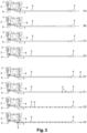
- step 3 The different stages of operation of the water injection system 1 are shown in figure 3 (steps A to H).
- pump 3 and injection line 5 are empty (A).
- the gases that were present in the injection line 5 exit from it at the level of the ejector 4. Once the water reaches the level of the ejector 4, it is ejected out of the injection line 5 by it (C, D).
- pump 3 is stopped and the water is no longer ejected from injection line 5 (E).
- the water remaining in the injection line 5 then begins to be purged.
- This air includes contaminants 9 such as bacteria or organic molecules.
- the water is conducted from the injection line 5 to the purge line 6 via the connector 7 and therefore via the sleeve 8.
- this sleeve 8 is made of copper.
- the sleeve 8 thus has a biocidal activity.
- contaminants can in particular be microorganisms such as bacteria, fungi or algae.
- the biocidal activity of the copper of the sleeve 8 prevents the microorganisms from forming a biofilm on the internal surface 8 of the sleeve.
- the biocidal activity of the copper of the sleeve 8 means that, even if the microorganisms manage to adhere to the internal surface of the sleeve 8, they do not have time to proliferate or secrete a matrix subsequently forming a biofilm before being destroyed by the copper. The obstruction of the device is thus avoided.
- the water which passes through the connector 7 and therefore through the sleeve 8 is thus decontaminated at least in part from the contaminants 9 which were contained in the air and which have spread and developed in the water (G, H). In this way, the water which returns to the tank 2 contains little or no microorganisms, for example bacteria, still capable of developing and potentially damaging the system.
- the device according to the invention for an aqueous solution other than water, for example for an aqueous solution comprising a mixture of water and ethanol.
Landscapes
- Engineering & Computer Science (AREA)
- Water Supply & Treatment (AREA)
- Chemical & Material Sciences (AREA)
- Combustion & Propulsion (AREA)
- General Engineering & Computer Science (AREA)
- Mechanical Engineering (AREA)
- Environmental & Geological Engineering (AREA)
- Organic Chemistry (AREA)
- Life Sciences & Earth Sciences (AREA)
- Hydrology & Water Resources (AREA)
- Health & Medical Sciences (AREA)
- Public Health (AREA)
- Apparatus For Disinfection Or Sterilisation (AREA)
- Agricultural Chemicals And Associated Chemicals (AREA)
- Jet Pumps And Other Pumps (AREA)
Description
- L'invention concerne les systèmes d'injection de solution aqueuse pour véhicule.
- Les systèmes d'injection d'eau pour véhicule comprennent généralement un réservoir d'eau, une pompe et une ligne d'injection menant à un éjecteur depuis lequel l'eau est éjectée. Après que le système d'injection d'eau a éjecté de l'eau via l'éjecteur, l'eau restant dans la ligne d'injection est purgée et retourne au réservoir. Cependant, au moins une partie de cette eau a été en contact avec de l'air qui est entrée dans la ligne d'injection après l'éjection. Cet air est notamment susceptible de contenir des composés organiques ou des micro-organismes tels que des bactéries. Il existe un risque que les micro-organismes ainsi introduits prolifèrent, ce qui n'est pas souhaitable. En effet, certains micro-organismes tels que des bactéries, des champignons ou des algues sont connus pour être capable d'adhérer à une surface et, à partir de celle-ci, proliférer et sécréter une matrice adhésive et protectrice formant ainsi un biofilm. La prolifération des micro-organismes et la formation d'un biofilm sont susceptibles de réduire au moins partiellement l'espace intérieur d'une conduite. Cette réduction peut être la cause de dysfonctionnements du système en influant notamment sur la pression et le débit avec lequel un liquide s'écoule dans la conduite. La prolifération des micro-organismes présents dans le biofilm peut être telle que le biofilm peut finir par obstruer complètement la conduite de manière à rendre le système inopérant et entraîner un risque important de détérioration des éléments le composant.
- Le document
EP 2 419 611 décrit un système d'injection de solution aqueuse pour véhicule conforme au préambule de la revendication 1. - Par ailleurs, lorsque la température est très basse, par exemple en hiver, il est important d'éviter que l'eau ne gèle afin de réduire le risque d'endommagement du dispositif. Une manière d'éviter que l'eau ne gèle consiste à chauffer au moins une partie du dispositif. On est alors confronté à deux problèmes, à savoir faire des économies d'énergie et chauffer des parties du dispositif où il n'est pas aisé d'intégrer un système de chauffage.
- Un but de l'invention est donc d'améliorer les systèmes d'injection de solution aqueuse pour véhicule.
- A cet effet, on prévoit selon l'invention un système d'injection de solution aqueuse de véhicule, comprenant :
- un réservoir de solution aqueuse en matière plastique,
- une pompe d'injection,
- un éjecteur de solution aqueuse,
- une ligne d'injection située entre la pompe et l'éjecteur,
- une ligne de purge située entre la ligne d'injection et le réservoir de solution aqueuse, et
- un raccord de sortie situé entre la ligne d'injection et la ligne de purge, le raccord présentant une face externe et une face interne, caractérisé en ce que le raccord forme un dispositif anti-obstruction apte à limiter ou empêcher la formation d'un biofilm, au moins une portion de la face interne du raccord étant faite ou recouverte d'un métal ou d'un matériau comprenant un métal, le métal étant sélectionné parmi le cuivre, l'argent, le zinc, l'aluminium, le nickel, l'or, le baryum, le plomb, l'étain, le bore, le thallium, l'antimoine, le cobalt, le zirconium, le molybdène, le titane, le fer, le chrome, et un alliage d'au moins deux d'entre eux, dans lequel un manchon réalisé dans le métal ou dans le matériau comprenant le métal est inséré dans le raccord et forme la portion ou toute la face interne du raccord.
- On peut par exemple prévoir que le métal est un alliage de cuivre et d'étain (bronze) ou de cuivre et de zinc (laiton). On peut également prévoir que l'alliage comprend du fer et du chrome (acier inoxydable).
- La face interne du raccord peut être recouverte du métal ou du matériau comprenant le métal par tout moyen connu de l'homme du métier. Les métaux sélectionnés présentent tous des propriétés biocides. Ces propriétés biocides sont notamment dues à l'effet oligodynamique. De cette façon, lorsque la solution aqueuse passe dans le raccord et est au contact d'au moins une portion de sa surface interne, les micro-organismes présents dans cette solution aqueuse, par exemple des bactéries, des champignons ou des algues, qui tentent d'adhérer à la face interne du raccord faite ou recouverte du métal ou du matériau comprenant le métal sont détruits et ne peuvent donc pas y adhérer. Cette propriété est notamment intéressante car de la solution aqueuse peut rester présente et stagner dans la ligne d'injection après que l'éjection de solution aqueuse a eu lieu puisque la totalité de la solution aqueuse n'est pas forcément purgée après l'éjection. Or, après l'éjection de la solution aqueuse, de l'air entre en contact avec la solution aqueuse présente dans la ligne d'injection, cet air comprenant généralement des micro-organismes tels que des bactéries, mais également d'autres éléments tels que des molécules organiques. Cette solution aqueuse résiduelle contaminée forme un milieu propice au développement de micro-organismes tels que des bactéries, des algues ou des champignons. En empêchant ces micro-organismes d'adhérer à la surface interne du raccord, la formation d'un biofilm est empêchée et, par conséquent, le risque d'obstruction du raccord, qu'elle soit partielle ou totale, est limité voire évité. Le raccord est un passage clé du système d'injection de solution aqueuse pour plusieurs raisons. Tout d'abord, l'espace interne délimité par celui-ci est généralement un des plus petits du système d'injection et est donc celui qui aura tendance à se boucher le plus facilement et le plus rapidement en cas de formation d'un biofilm. De plus, comme indiqué précédemment, le raccord est situé à un endroit du système où la solution aqueuse peut stagner après que l'éjection et la purge aient eu lieu, cette solution aqueuse stagnante étant propice au développement de micro-organismes. Le système selon l'invention permet d'éviter que plus de 20% d'un volume interne délimité par le raccord soit obstrué par un biofilm. On peut même réduire ce risque à 10% ou 5% du volume interne, voire supprimer totalement ce risque. Ainsi, pour les raisons évoquées ci-dessus, le fait que ce soit le raccord qui présente une face interne faite ou recouverte d'un métal ou d'un matériau comprenant un métal tel que décrit précédemment est particulièrement efficace pour éviter la formation d'un biofilm et donc une obstruction du système.
- Par « activité biocide », on comprend qu'au moins 50 % des micro-organismes, notamment des bactéries, mis en contact avec la surface interne du raccord sont détruits, par exemple au moins 60 %, de préférence au moins 70 %, de préférence encore au moins 80 %, voire au moins 90 %. Parmi les micro-organismes sensibles au métal ou au matériau comprenant un métal selon l'invention on trouve notamment des bactéries à Gram négatif telles que Pseudomonas aeruginosa ou Escherichia coli, ainsi que des bactéries à Gram positif telles que Staphylococcus aureus. Des levures telles que Saccharomyces cerevisiae, et des algues du genre Chlorella ou Stichococcus, telle que par exemple Chlorella protothecoides, sont également sensibles au métal ou au matériau comprenant un métal selon l'invention. D'autres types de micro-organismes, par exemple des champignons, sont également sensibles au métal ou au matériau comprenant un métal selon l'invention. Les micro-organismes ainsi détruits ne sont plus capables d'adhérer à la surface interne du raccord et ne peuvent donc pas former de biofilm et obstruer un volume interne du raccord.
- L'expression « solution aqueuse » comprend notamment de l'eau. Cette eau est déminéralisée ou non. Elle comprend également des micro-organismes tels que des bactéries ou non. Cette expression comprend également des mélanges d'eau et d'éthanol, par exemple des mélanges comprenant de l'eau et entre 10% et 55% en volume d'éthanol, de préférence entre 20% et 40% en volume d'éthanol. De telles proportions d'éthanol évitent que l'eau présente dans la solution aqueuse ne gèle. On peut prévoir que l'expression « solution aqueuse » ne comprend pas des solutions aqueuses comprenant de l'urée, comme par exemple des solutions d'AdBlue®. En effet, la présence de métaux dans des systèmes utilisant des solutions aqueuses d'urée (par exemple des systèmes utilisant la technique de réduction catalytique sélective (SCR)) n'est pas souhaitée car ces dernières ont un effet corrosif sur les métaux.
- Par ailleurs, au moins une partie du système d'injection peut être chauffée. Ce chauffage est notamment nécessaire lorsque la température est trop basse et qu'un risque de gel existe. Dans le cas présent, le métal ou le matériau comprenant le métal sont des conducteurs thermiques de sorte que si un élément du dispositif est chauffé, le métal ou le matériau comprenant le métal transfère par conduction la chaleur depuis l'élément qui est chauffé vers le raccord de sortie. De préférence, l'élément qui est chauffé est un élément du dispositif spatialement proche du raccord de sortie. On peut par exemple prévoir que la ligne d'injection ou la ligne de purge est chauffée. L'avantage de cette caractéristique réside aussi dans l'économie d'énergie qui est réalisée puisqu'on réutilise l'énergie déjà utilisée pour chauffer le premier élément afin de chauffer le raccord.
- Par l'expression « faite ou recouverte d'un métal » on comprend que la portion de la surface interne est faite ou recouverte d'un matériau fait à 100 % du métal. Par exemple, la portion de la surface interne est faite ou recouverte d'un matériau fait à 100% de cuivre, à 100 % d'argent, à 100 % de zinc, à 100 % d'aluminium, à 100 % de nickel, à 100 % d'or, à 100 % de baryum, à 100 % de plomb, à 100 d'étain, à 100% de bore, à 100 % de thallium, à 100 % d'antimoine, à 100 % de cobalt, à 100 % de zirconium, à 100 % de molybdène, à 100 % de titane, à 100 % de fer, à 100% de chrome ou à 100 % d'un alliage d'au moins deux de ces métaux, par exemple d'un alliage de cuivre et de zinc (laiton) ou d'un alliage de cuivre et d'étain (bronze).
- De préférence, le métal est sélectionné parmi le cuivre, l'argent et le zinc.
- De manière préférée, toute la face interne du raccord est faite du métal ou du matériau comprenant le métal.
- On augmente ainsi la surface sur laquelle les micro-organismes ne peuvent pas adhérer pour former de biofilms et donc on réduit encore le risque d'obstruction, même partielle, d'un volume interne délimité par le raccord.
- Selon l'invention, un manchon réalisé dans le métal ou dans le matériau comprenant le métal est inséré dans le raccord et forme la portion ou toute la face interne du raccord.
- Le manchon est de préférence de forme circulaire et d'un diamètre légèrement inférieur à celui du diamètre interne du raccord de façon à pouvoir être logé aisément et de façon stable à l'intérieur de celui-ci.
- On peut prévoir qu'une paroi du raccord comprend au moins deux matériaux, un de ces matériaux étant le métal ou le matériau comprenant le métal qui recouvre la portion ou toute la face interne du raccord et qui forme une couche d'une épaisseur comprise entre 1 µm et 10 cm.
- On peut par exemple prévoir une couche ayant une épaisseur permettant de remplir presque en totalité un diamètre interne du raccord.
- De manière avantageuse, le métal étant un premier métal, le raccord comprend un corps fait en un second métal, le corps étant recouvert sur au moins une portion d'une face interne de celui-ci par le premier métal, le premier métal formant au moins une portion de la face interne du raccord.
- On peut prévoir que le corps qui est fait dans le second métal forme également une portion de la face interne du raccord. On peut également prévoir que le second métal est choisi parmi le cuivre, l'argent, le zinc, l'aluminium, le nickel, l'or, le baryum, le plomb, l'étain, le bore, le thallium, l'antimoine, le cobalt, le zirconium, le molybdène, le titane, le fer, le chrome, et un alliage d'au moins deux d'entre eux, par exemple un alliage de cuivre et de zinc (laiton) ou un alliage de cuivre et d'étain (bronze). On peut aussi prévoir que les premier et second métaux formant chacun une portion de la face interne du raccord sont deux métaux différents qui présentent des propriétés biocides différentes, de préférence des propriétés biocides complémentaires.
- On peut également prévoir que le corps est fait d'un alliage métallique, d'un alliage comprenant un acier, d'un alliage comprenant un acier inoxydable ou d'un alliage comprenant de l'aluminium.
- On peut par exemple prévoir que le corps est en acier inoxydable et que le premier métal recouvrant le corps est un alliage de cuivre et d'argent. De préférence, cet alliage de cuivre et d'argent comprend 10 % en poids d'argent.
- De manière préférée, le raccord forme un mamelon ou un manchon.
- Avantageusement, le matériau comprenant un métal comprend 60 % à 95 % en poids de cuivre, 3 % à 45 % en poids de Zinc, ou 90 % à 99 % en poids d'argent.
- De préférence, le matériau comprenant le métal a une conductivité thermique supérieure à 0,5 W.m-1.K-1 à 20°C.
- On peut par exemple prévoir que le matériau comprenant un métal a une conductivité thermique supérieure à 20 W.m-1.K-1 à 20°C, de préférence supérieure à 40 W.m-1.K-1 à 20°C, voire supérieure à 60 W.m-1.K-1 à 20°C. Une grande valeur de conductivité thermique permet une meilleure conduction de la chaleur depuis un élément chauffé jusqu'au raccord. Une meilleure conduction de la chaleur permet notamment de faire des économies en termes d'énergie consommée.
- De manière avantageuse, le matériau comprenant un métal comprend une matrice polymérique dans laquelle le métal est dispersé sous forme de charge.
- Le matériau est de cette façon plus léger et moins coûteux à produire qu'un matériau fait uniquement de métal. On peut par exemple prévoir que la matrice polymérique est du polyéthylène haute densité (HDPE).
- Avantageusement, le matériau comprenant un métal comprend un acier inoxydable ou un alliage comprenant un acier inoxydable.
- L'acier inoxydable est connu pour avoir une activité antimicrobienne comme cela est par exemple montré dans le document
WO1999064640 A1 . - Dans un mode de réalisation, le matériau comprenant un métal comprend un acier inoxydable comprenant 2,5 % à 4,5 % en poids de cuivre, 0,04 % à 0,06 % en poids d'argent, ou une quantité égale ou supérieure à 0,0005 % en poids d'un oxyde d'argent.
- On peut également prévoir que le matériau comprenant un métal comprend un alliage métallique, un alliage comprenant un acier, ou un alliage comprenant de l'aluminium.
- Dans un mode de réalisation préférée, la solution aqueuse est de l'eau.
- L'invention concerne également un véhicule comprenant un système d'injection de solution aqueuse tel que décrit précédemment.
- On peut prévoir que le système d'injection de solution aqueuse est configuré pour injecter la solution aqueuse sur un composant ou un système du véhicule présent entre le point d'aspiration d'air du moteur et la chambre de combustion (y compris la chambre de combustion elle-même).
- On peut également prévoir que le système d'injection de solution aqueuse est configuré pour injecter la solution aqueuse dans le système d'alimentation en carburant, entre le point d'aspiration du réservoir à carburant jusqu'au point d'injection dans le moteur.
- On décrit également un procédé de bio-décontamination d'un système d'injection de solution aqueuse de véhicule, dans lequel :
- de la solution aqueuse est pompée depuis un réservoir en matière plastique vers un éjecteur à travers une ligne d'injection,
- la solution aqueuse pompée est éjectée par l'éjecteur,
- après l'éjection, on purge la solution aqueuse restée dans la ligne d'injection, au cours de la purge, la solution aqueuse est mise en contact avec au moins une surface en métal ou en matériau comprenant au moins un métal, le métal étant sélectionné parmi le cuivre, l'argent, le zinc, l'aluminium, le nickel, l'or, le baryum, le plomb, l'étain, le bore, le thallium, l'antimoine, le cobalt, le zirconium, le molybdène, le titane, le fer, le chrome, et un alliage d'au moins deux d'entre eux.
- On peut par exemple prévoir que le métal est un alliage de cuivre et d'étain (bronze) ou de cuivre et de zinc (laiton). On peut également prévoir que l'alliage comprend du fer et du chrome (acier inoxydable).
- Nous allons maintenant présenter un mode de réalisation de l'invention donné à titre d'exemple non limitatif et à l'appui des figures annexées sur lesquelles :
- la
figure 1 est une vue en coupe longitudinale d'un système d'injection de solution aqueuse selon l'invention ; - la
figure 2 est une représentation schématique du système d'injection de solution aqueuse de lafigure 1 ; et - la
figure 3 est une vue en coupe longitudinale du système d'injection de solution aqueuse de lafigure 1 à différentes étape d'un procédé de bio-décontamination selon l'invention. - Nous allons présenter un mode de réalisation du système d'injection d'eau montrant les avantages de l'invention.
- Dans le cas présent, on met en oeuvre l'invention dans un véhicule fonctionnant avec un moteur thermique, par exemple un moteur à essence. Bien entendu, d'autres types de véhicules peuvent être envisagés.
- Un système d'injection d'eau 1 selon l'invention comprend un réservoir d'eau 2 en matière plastique, une pompe d'injection 3, un éjecteur 4, une ligne d'injection 5, une ligne de purge 6 et un raccord de sortie 7 (voir
figures 1 à 3 ). - Dans le cas présent, le raccord de sortie 7 est un mamelon. On peut bien entendu prévoir que le raccord de sortie 7 est une autre pièce, par exemple un manchon. Le raccord 7 est disposé entre la pompe d'injection 3 et la ligne d'injection 5. Il est également disposé entre la ligne d'injection 5 et la ligne de purge 6. Le raccord 7 a une forme générale cylindrique circulaire creuse.
- Un manchon 8 en métal est présent à l'intérieur du raccord 7. Le manchon 8 a une forme générale cylindrique circulaire creuse. Il a un diamètre externe légèrement inférieur au diamètre interne du raccord 7 de sorte qu'il peut être facilement inséré dans celui-ci de façon stable. Dans le cas présent, le manchon 8 est en cuivre. Bien entendu, on peut prévoir que le manchon est fait d'un autre métal, notamment d'un métal sélectionné parmi l'argent, le zinc, l'aluminium, le nickel, l'or, le baryum, le plomb, l'étain, le bore, le thallium, l'antimoine, le cobalt, le zirconium, le molybdène, le titane, le fer, le chrome, et un alliage d'au moins deux d'entre eux, par exemple un alliage de cuivre et de zinc (laiton) ou d'un alliage de cuivre et d'étain (bronze). Dans un mode de réalisation alternatif, on peut prévoir que le manchon est fait d'une matière comprenant du métal et une autre matière, par exemple une matrice polymérique (par exemple du polyéthylène haute densité ou HDPE) dans laquelle le métal (par exemple le zinc) est dispersé sous forme de charge.
- La pompe d'injection 3 est apte à pomper l'eau présente dans le réservoir d'eau et à l'injecter dans la ligne d'injection 5 en passant par le raccord 7.
- La ligne d'injection 5 présente deux extrémités, une raccordée au raccord 7 et une raccordée à l'éjecteur 4.
- Les différentes étapes du fonctionnement du système d'injection d'eau 1 sont représentées à la
figure 3 (étapes A à H). - Dans un premier temps, la pompe 3 et la ligne d'injection 5 sont vides (A).
- Ensuite, la pompe 3 est mise en marche et elle, ainsi que la ligne d'injection 5, se remplissent d'eau pompée dans le réservoir 2 (B).
- Les gaz qui étaient présents dans la ligne d'injection 5 sortent de celle-ci au niveau de l'éjecteur 4. Une fois que l'eau arrive au niveau de l'éjecteur 4, elle est éjectée hors de la ligne d'injection 5 par celui-ci (C, D).
- Une fois que la quantité d'eau désirée a été éjectée, la pompe 3 est arrêtée et l'eau n'est plus éjectée de la ligne d'injection 5 (E).
- L'eau restant dans la ligne de d'injection 5 commence alors à être purgée. Lors de la purge, de l'air entre dans la ligne d'injection 5 (F). Cet air comprend des contaminants 9 tels que des bactéries ou des molécules organiques. Au cours de la purge, l'eau est conduite depuis la ligne d'injection 5 vers la ligne de purge 6 en passant par le raccord 7 et donc par le manchon 8. Comme indiqué précédemment, dans le cas présent, ce manchon 8 est en cuivre. Le manchon 8 présente ainsi une activité biocide. A la fin de la purge, il reste de l'eau qui a été contaminée par des contaminants 9 qui stagne dans le raccord 7 et donc dans le manchon 8. Ces contaminants peuvent notamment être des micro-organismes tels que des bactéries, des champignons ou des algues. L'activité biocide du cuivre du manchon 8 empêche les micro-organismes de former un biofilm sur la surface interne 8 du manchon. En effet, l'activité biocide du cuivre du manchon 8 fait que, même si les micro-organismes arrivent à adhérer à la surface interne du manchon 8, ils n'ont pas le temps de proliférer ou de secréter une matrice formant par la suite un biofilm avant d'être détruits par le cuivre. L'obstruction du dispositif est ainsi évitée. Par ailleurs, on peut noter que l'eau qui passe par le raccord 7 et donc par le manchon 8 est ainsi décontaminée au moins en partie des contaminants 9 qui étaient contenus dans l'air et qui se sont répandus et développés dans l'eau (G, H). De cette façon, l'eau qui retourne dans le réservoir 2 ne contient pas ou peu de micro-organismes, par exemple des bactéries, encore capables de se développer et de potentiellement endommager le système.
- Il est possible d'utiliser le dispositif selon l'invention pour une solution aqueuse autre que de l'eau, par exemple pour une solution aqueuse comprenant un mélange d'eau et d'éthanol.
Claims (11)
- Système d'injection de solution aqueuse (1) de véhicule, comprenant- un réservoir de solution aqueuse (2) en matière plastique,- une pompe d'injection (3),- un éjecteur de solution aqueuse (4),- une ligne d'injection (5) située entre la pompe et l'éjecteur,- une ligne de purge (6) située entre la ligne d'injection et le réservoir de solution aqueuse, et- un raccord (7) de sortie situé entre la ligne d'injection (5) et la ligne de purge (6), le raccord présentant une face externe et une face interne et formant un dispositif anti-obstruction apte à limiter ou empêcher la formation d'un biofilm, au moins une portion de la face interne du raccord étant faite ou recouverte d'un métal ou d'un matériau comprenant un métal, le métal étant sélectionné parmi le cuivre, l'argent, le zinc, l'aluminium, le nickel, l'or, le baryum, le plomb, l'étain, le bore, le thallium, l'antimoine, le cobalt, le zirconium, le molybdène, le titane, le fer, le chrome, et un alliage d'au moins deux d'entre eux,le système étant caractérisé par un manchon (8) réalisé dans le métal ou dans le matériau comprenant le métal inséré dans le raccord (7) et formant la portion ou toute la face interne du raccord.
- Système d'injection de solution aqueuse (1) de véhicule selon la revendication 1, dans lequel le métal est sélectionné parmi le cuivre, l'argent et le zinc.
- Système d'injection de solution aqueuse (1) de véhicule selon l'une quelconque des revendications précédentes, dans lequel toute la face interne du raccord (7) est faite du métal ou du matériau comprenant le métal.
- Système d'injection de solution aqueuse (1) de véhicule selon l'une quelconque des revendications précédentes, dans lequel le métal étant un premier métal, le raccord (7) comprend un corps fait en un second métal, le corps étant recouvert sur au moins une portion d'une face interne de celui-ci par le premier métal, le premier métal formant au moins une portion de la face interne du raccord.
- Système d'injection de solution aqueuse (1) de véhicule selon l'une quelconque des revendications précédentes, dans lequel le raccord (7) forme un mamelon ou un manchon.
- Système d'injection de solution aqueuse (1) de véhicule selon l'une quelconque des revendications précédentes dans lequel le matériau comprenant un métal comprend 60 % à 95 % en poids de cuivre, 3 % à 45 % en poids de Zinc, ou 90 % à 99 % en poids d'argent.
- Système d'injection de solution aqueuse (1) de véhicule selon l'une quelconque des revendications précédentes, dans lequel le matériau comprenant un métal a une conductivité thermique supérieure à 0,5 W.m-1.K-1 à 20°C.
- Système d'injection de solution aqueuse (1) de véhicule selon l'une quelconque des revendications précédentes, dans lequel le matériau comprenant un métal comprend une matrice polymérique dans laquelle le métal est dispersé sous forme de charge.
- Système d'injection de solution aqueuse (1) de véhicule selon l'une quelconque des revendications précédentes, dans lequel le matériau comprenant un métal comprend un acier inoxydable ou un alliage comprenant un acier inoxydable.
- Système d'injection de solution aqueuse (1) de véhicule selon l'une quelconque des revendications précédentes, dans lequel la solution aqueuse est de l'eau.
- Véhicule comprenant un système d'injection de solution aqueuse (1) selon l'une quelconque des revendications 1 à 10.
Applications Claiming Priority (2)
| Application Number | Priority Date | Filing Date | Title |
|---|---|---|---|
| FR1850932A FR3077602B1 (fr) | 2018-02-05 | 2018-02-05 | Systeme d'injection de solution aqueuse pour vehicule |
| PCT/EP2019/052754 WO2019149956A1 (fr) | 2018-02-05 | 2019-02-05 | Système d'injection de solution aqueuse pour véhicule |
Publications (3)
| Publication Number | Publication Date |
|---|---|
| EP3749846A1 EP3749846A1 (fr) | 2020-12-16 |
| EP3749846B1 true EP3749846B1 (fr) | 2024-10-16 |
| EP3749846C0 EP3749846C0 (fr) | 2024-10-16 |
Family
ID=61802195
Family Applications (1)
| Application Number | Title | Priority Date | Filing Date |
|---|---|---|---|
| EP19705129.5A Active EP3749846B1 (fr) | 2018-02-05 | 2019-02-05 | Système d'injection de solution aqueuse pour véhicule |
Country Status (3)
| Country | Link |
|---|---|
| EP (1) | EP3749846B1 (fr) |
| FR (1) | FR3077602B1 (fr) |
| WO (1) | WO2019149956A1 (fr) |
Family Cites Families (7)
| Publication number | Priority date | Publication date | Assignee | Title |
|---|---|---|---|---|
| TW444060B (en) | 1998-06-05 | 2001-07-01 | Kawasaki Steel Co | Stainless steel product having excellent antimicrobial activity and method for production thereof |
| DE10217649A1 (de) * | 2002-04-19 | 2004-01-08 | Stadelmann, Heinz W., Dr. | Entkeimungssystem, insbesondere zur Entkeimung von Trink- und Brauchwasser sowie Herstellung und Verwendung des Entkeimungssystems |
| US20080110812A1 (en) * | 2006-11-13 | 2008-05-15 | Mahle Tennex Industries, Inc. | Separated water treatment system for diesel fuel engine |
| WO2010119116A2 (fr) * | 2009-04-16 | 2010-10-21 | Inergy Automotive Systems Research (Société Anonyme) | Système et procédé de stockage d'un additif et d'injection de celui-ci dans les gaz d'échappement d'un moteur |
| US9404449B2 (en) * | 2011-11-25 | 2016-08-02 | NOX—Reducts Technology SA | Apparatus for treating a mixture of fossil fuel and water prior to combustion in combustion engines |
| US20130327419A1 (en) * | 2012-02-22 | 2013-12-12 | Applied Silver, Inc. | Antimicrobial device |
| DE102015208477A1 (de) * | 2015-05-07 | 2016-11-10 | Robert Bosch Gmbh | Vorrichtung und Verfahren zur Einspritzung von Wasser einer Brennkraftmaschine |
-
2018
- 2018-02-05 FR FR1850932A patent/FR3077602B1/fr active Active
-
2019
- 2019-02-05 WO PCT/EP2019/052754 patent/WO2019149956A1/fr not_active Ceased
- 2019-02-05 EP EP19705129.5A patent/EP3749846B1/fr active Active
Also Published As
| Publication number | Publication date |
|---|---|
| WO2019149956A1 (fr) | 2019-08-08 |
| FR3077602B1 (fr) | 2021-01-15 |
| EP3749846A1 (fr) | 2020-12-16 |
| EP3749846C0 (fr) | 2024-10-16 |
| FR3077602A1 (fr) | 2019-08-09 |
Similar Documents
| Publication | Publication Date | Title |
|---|---|---|
| CA2515023C (fr) | Manchon a insert pour la reparation d'une canalisation de transport de fluide a haute pression. | |
| BE1005554A3 (fr) | Procede de fabrication d'un tube a paroi multiple. | |
| EP2717987B1 (fr) | Filtre à liquide et sous-ensemble de moteur formant support de montage pour une cartouche filtrante | |
| FR2921455A1 (fr) | Systeme pour engrenage avec lubrification. | |
| WO2021233964A1 (fr) | Dispositif et procédé de transfert de fluide cryogénique | |
| EP3079791B1 (fr) | Filtre à carburant et cartouche pour un tel filtre avec réservoir d'additif embarqué. | |
| FR2701895A1 (fr) | Plaque de busette et son procédé de traitement de surface. | |
| EP3079792A1 (fr) | Filtre à carburant avec dispositif de libération d'additif | |
| EP3749846B1 (fr) | Système d'injection de solution aqueuse pour véhicule | |
| CA2647160A1 (fr) | Accessoire sertissable de raccordement pour canalisations | |
| FR3080733A1 (fr) | Dispositif anti-ballottement chauffant pour reservoir de produits aqueux | |
| FR3057644A1 (fr) | Procede et dispositif de remplissage d'un reservoir de gaz sous pression | |
| EP0843124B1 (fr) | Procédé de transport d'un fluide dans une conduite comportant une structure poreuse | |
| FR2726329A1 (fr) | Appareil pour refouler du carburant d'un reservoir dans un moteur a combustion interne | |
| WO2011124770A1 (fr) | Réservoir de fluide avec système de mise à l'air | |
| FR2888289A1 (fr) | Dispositif d'injection d'additif liquide dans le circuit d'alimentation en carburant d'un moteur a combustion interne de vehicule automobile | |
| EP3094916A1 (fr) | Système de protection thermique pour un réservoir cryogénique d'engin spatial | |
| FR2974778A1 (fr) | Circuit de distribution de liquide lave-glace pour vehicule automobile et procede de protection d'un tel circuit. | |
| FR3065273A1 (fr) | Procede de fixation d'un element d'ancrage sur un element d'armure d'une conduite flexible, conduite et methode de montage associees | |
| EP0015193A1 (fr) | Réservoir perfectionné à liquide | |
| EP2213858B1 (fr) | Dispositif de rechauffage du liquide de lave-glace d'un vehicule automobile | |
| FR2901599A1 (fr) | Echangeur de chaleur, notamment pour le refroidissement des gaz d'echappement d'un vehicule | |
| EP3149320B1 (fr) | Boîtier de décantation par gravité pour un circuit de circulation de liquide | |
| EP3803074B1 (fr) | Système de stockage d'une solution aqueuse pour véhicule automobile | |
| CA3255982A1 (fr) | Cryogenic fluid storage and distribution process and facility |
Legal Events
| Date | Code | Title | Description |
|---|---|---|---|
| STAA | Information on the status of an ep patent application or granted ep patent |
Free format text: STATUS: UNKNOWN |
|
| STAA | Information on the status of an ep patent application or granted ep patent |
Free format text: STATUS: THE INTERNATIONAL PUBLICATION HAS BEEN MADE |
|
| PUAI | Public reference made under article 153(3) epc to a published international application that has entered the european phase |
Free format text: ORIGINAL CODE: 0009012 |
|
| STAA | Information on the status of an ep patent application or granted ep patent |
Free format text: STATUS: REQUEST FOR EXAMINATION WAS MADE |
|
| 17P | Request for examination filed |
Effective date: 20200905 |
|
| AK | Designated contracting states |
Kind code of ref document: A1 Designated state(s): AL AT BE BG CH CY CZ DE DK EE ES FI FR GB GR HR HU IE IS IT LI LT LU LV MC MK MT NL NO PL PT RO RS SE SI SK SM TR |
|
| AX | Request for extension of the european patent |
Extension state: BA ME |
|
| DAV | Request for validation of the european patent (deleted) | ||
| DAX | Request for extension of the european patent (deleted) | ||
| STAA | Information on the status of an ep patent application or granted ep patent |
Free format text: STATUS: EXAMINATION IS IN PROGRESS |
|
| 17Q | First examination report despatched |
Effective date: 20221108 |
|
| P01 | Opt-out of the competence of the unified patent court (upc) registered |
Effective date: 20230515 |
|
| GRAP | Despatch of communication of intention to grant a patent |
Free format text: ORIGINAL CODE: EPIDOSNIGR1 |
|
| STAA | Information on the status of an ep patent application or granted ep patent |
Free format text: STATUS: GRANT OF PATENT IS INTENDED |
|
| INTG | Intention to grant announced |
Effective date: 20240527 |
|
| GRAS | Grant fee paid |
Free format text: ORIGINAL CODE: EPIDOSNIGR3 |
|
| GRAA | (expected) grant |
Free format text: ORIGINAL CODE: 0009210 |
|
| STAA | Information on the status of an ep patent application or granted ep patent |
Free format text: STATUS: THE PATENT HAS BEEN GRANTED |
|
| AK | Designated contracting states |
Kind code of ref document: B1 Designated state(s): AL AT BE BG CH CY CZ DE DK EE ES FI FR GB GR HR HU IE IS IT LI LT LU LV MC MK MT NL NO PL PT RO RS SE SI SK SM TR |
|
| REG | Reference to a national code |
Ref country code: GB Ref legal event code: FG4D Free format text: NOT ENGLISH |
|
| REG | Reference to a national code |
Ref country code: CH Ref legal event code: EP |
|
| REG | Reference to a national code |
Ref country code: IE Ref legal event code: FG4D Free format text: LANGUAGE OF EP DOCUMENT: FRENCH |
|
| REG | Reference to a national code |
Ref country code: DE Ref legal event code: R096 Ref document number: 602019060432 Country of ref document: DE |
|
| U01 | Request for unitary effect filed |
Effective date: 20241114 |
|
| P04 | Withdrawal of opt-out of the competence of the unified patent court (upc) registered |
Free format text: CASE NUMBER: APP_66591/2024 Effective date: 20241216 |
|
| U07 | Unitary effect registered |
Designated state(s): AT BE BG DE DK EE FI FR IT LT LU LV MT NL PT RO SE SI Effective date: 20241219 |
|
| U20 | Renewal fee for the european patent with unitary effect paid |
Year of fee payment: 7 Effective date: 20250227 |
|
| PG25 | Lapsed in a contracting state [announced via postgrant information from national office to epo] |
Ref country code: HR Free format text: LAPSE BECAUSE OF FAILURE TO SUBMIT A TRANSLATION OF THE DESCRIPTION OR TO PAY THE FEE WITHIN THE PRESCRIBED TIME-LIMIT Effective date: 20241016 Ref country code: IS Free format text: LAPSE BECAUSE OF FAILURE TO SUBMIT A TRANSLATION OF THE DESCRIPTION OR TO PAY THE FEE WITHIN THE PRESCRIBED TIME-LIMIT Effective date: 20250216 |
|
| PG25 | Lapsed in a contracting state [announced via postgrant information from national office to epo] |
Ref country code: ES Free format text: LAPSE BECAUSE OF FAILURE TO SUBMIT A TRANSLATION OF THE DESCRIPTION OR TO PAY THE FEE WITHIN THE PRESCRIBED TIME-LIMIT Effective date: 20241016 |
|
| PG25 | Lapsed in a contracting state [announced via postgrant information from national office to epo] |
Ref country code: NO Free format text: LAPSE BECAUSE OF FAILURE TO SUBMIT A TRANSLATION OF THE DESCRIPTION OR TO PAY THE FEE WITHIN THE PRESCRIBED TIME-LIMIT Effective date: 20250116 |
|
| PG25 | Lapsed in a contracting state [announced via postgrant information from national office to epo] |
Ref country code: GR Free format text: LAPSE BECAUSE OF FAILURE TO SUBMIT A TRANSLATION OF THE DESCRIPTION OR TO PAY THE FEE WITHIN THE PRESCRIBED TIME-LIMIT Effective date: 20250117 |
|
| PG25 | Lapsed in a contracting state [announced via postgrant information from national office to epo] |
Ref country code: PL Free format text: LAPSE BECAUSE OF FAILURE TO SUBMIT A TRANSLATION OF THE DESCRIPTION OR TO PAY THE FEE WITHIN THE PRESCRIBED TIME-LIMIT Effective date: 20241016 |
|
| PG25 | Lapsed in a contracting state [announced via postgrant information from national office to epo] |
Ref country code: RS Free format text: LAPSE BECAUSE OF FAILURE TO SUBMIT A TRANSLATION OF THE DESCRIPTION OR TO PAY THE FEE WITHIN THE PRESCRIBED TIME-LIMIT Effective date: 20250116 |
|
| PG25 | Lapsed in a contracting state [announced via postgrant information from national office to epo] |
Ref country code: SM Free format text: LAPSE BECAUSE OF FAILURE TO SUBMIT A TRANSLATION OF THE DESCRIPTION OR TO PAY THE FEE WITHIN THE PRESCRIBED TIME-LIMIT Effective date: 20241016 |
|
| RAP4 | Party data changed (patent owner data changed or rights of a patent transferred) |
Owner name: OPMOBILITY C-POWER BELGIUM RESEARCH |
|
| U1H | Name or address of the proprietor changed after the registration of the unitary effect |
Owner name: OPMOBILITY C-POWER BELGIUM RESEARCH; BE |
|
| PG25 | Lapsed in a contracting state [announced via postgrant information from national office to epo] |
Ref country code: SK Free format text: LAPSE BECAUSE OF FAILURE TO SUBMIT A TRANSLATION OF THE DESCRIPTION OR TO PAY THE FEE WITHIN THE PRESCRIBED TIME-LIMIT Effective date: 20241016 |
|
| PG25 | Lapsed in a contracting state [announced via postgrant information from national office to epo] |
Ref country code: CZ Free format text: LAPSE BECAUSE OF FAILURE TO SUBMIT A TRANSLATION OF THE DESCRIPTION OR TO PAY THE FEE WITHIN THE PRESCRIBED TIME-LIMIT Effective date: 20241016 |
|
| PLBE | No opposition filed within time limit |
Free format text: ORIGINAL CODE: 0009261 |
|
| STAA | Information on the status of an ep patent application or granted ep patent |
Free format text: STATUS: NO OPPOSITION FILED WITHIN TIME LIMIT |
|
| PG25 | Lapsed in a contracting state [announced via postgrant information from national office to epo] |
Ref country code: MC Free format text: LAPSE BECAUSE OF FAILURE TO SUBMIT A TRANSLATION OF THE DESCRIPTION OR TO PAY THE FEE WITHIN THE PRESCRIBED TIME-LIMIT Effective date: 20241016 |
|
| 26N | No opposition filed |
Effective date: 20250717 |
|
| REG | Reference to a national code |
Ref country code: CH Ref legal event code: PL |
|
| PG25 | Lapsed in a contracting state [announced via postgrant information from national office to epo] |
Ref country code: CH Free format text: LAPSE BECAUSE OF NON-PAYMENT OF DUE FEES Effective date: 20250228 |
|
| GBPC | Gb: european patent ceased through non-payment of renewal fee |
Effective date: 20250205 |
|
| PG25 | Lapsed in a contracting state [announced via postgrant information from national office to epo] |
Ref country code: GB Free format text: LAPSE BECAUSE OF NON-PAYMENT OF DUE FEES Effective date: 20250205 |
|
| PG25 | Lapsed in a contracting state [announced via postgrant information from national office to epo] |
Ref country code: IE Free format text: LAPSE BECAUSE OF NON-PAYMENT OF DUE FEES Effective date: 20250205 |
|
| U20 | Renewal fee for the european patent with unitary effect paid |
Year of fee payment: 8 Effective date: 20260227 |