EP3749835B1 - Downhole system with sliding sleeve - Google Patents
Downhole system with sliding sleeve Download PDFInfo
- Publication number
- EP3749835B1 EP3749835B1 EP19704306.0A EP19704306A EP3749835B1 EP 3749835 B1 EP3749835 B1 EP 3749835B1 EP 19704306 A EP19704306 A EP 19704306A EP 3749835 B1 EP3749835 B1 EP 3749835B1
- Authority
- EP
- European Patent Office
- Prior art keywords
- sliding sleeve
- sealing element
- metal structure
- opening
- pressure
- Prior art date
- Legal status (The legal status is an assumption and is not a legal conclusion. Google has not performed a legal analysis and makes no representation as to the accuracy of the status listed.)
- Active
Links
- 238000007789 sealing Methods 0.000 claims description 126
- 239000002184 metal Substances 0.000 claims description 77
- 239000012530 fluid Substances 0.000 claims description 31
- 238000007373 indentation Methods 0.000 claims description 15
- 230000004888 barrier function Effects 0.000 claims description 8
- 239000000463 material Substances 0.000 claims description 4
- 230000000149 penetrating effect Effects 0.000 claims description 3
- 239000003921 oil Substances 0.000 description 9
- 238000004519 manufacturing process Methods 0.000 description 8
- 239000007789 gas Substances 0.000 description 5
- VNWKTOKETHGBQD-UHFFFAOYSA-N methane Chemical compound C VNWKTOKETHGBQD-UHFFFAOYSA-N 0.000 description 4
- 229920002530 polyetherether ketone Polymers 0.000 description 3
- XLYOFNOQVPJJNP-UHFFFAOYSA-N water Substances O XLYOFNOQVPJJNP-UHFFFAOYSA-N 0.000 description 3
- 230000006835 compression Effects 0.000 description 2
- 238000007906 compression Methods 0.000 description 2
- 239000010779 crude oil Substances 0.000 description 2
- 239000003345 natural gas Substances 0.000 description 2
- 230000003247 decreasing effect Effects 0.000 description 1
- 230000000694 effects Effects 0.000 description 1
- 230000002708 enhancing effect Effects 0.000 description 1
- 239000011499 joint compound Substances 0.000 description 1
- 238000012986 modification Methods 0.000 description 1
- 230000004048 modification Effects 0.000 description 1
- 229920000642 polymer Polymers 0.000 description 1
- 230000002035 prolonged effect Effects 0.000 description 1
- 239000000126 substance Substances 0.000 description 1
- 238000013022 venting Methods 0.000 description 1
Images


Classifications
-
- E—FIXED CONSTRUCTIONS
- E21—EARTH DRILLING; MINING
- E21B—EARTH DRILLING, e.g. DEEP DRILLING; OBTAINING OIL, GAS, WATER, SOLUBLE OR MELTABLE MATERIALS OR A SLURRY OF MINERALS FROM WELLS
- E21B33/00—Sealing or packing boreholes or wells
- E21B33/10—Sealing or packing boreholes or wells in the borehole
- E21B33/12—Packers; Plugs
- E21B33/128—Packers; Plugs with a member expanded radially by axial pressure
- E21B33/1285—Packers; Plugs with a member expanded radially by axial pressure by fluid pressure
-
- E—FIXED CONSTRUCTIONS
- E21—EARTH DRILLING; MINING
- E21B—EARTH DRILLING, e.g. DEEP DRILLING; OBTAINING OIL, GAS, WATER, SOLUBLE OR MELTABLE MATERIALS OR A SLURRY OF MINERALS FROM WELLS
- E21B34/00—Valve arrangements for boreholes or wells
- E21B34/06—Valve arrangements for boreholes or wells in wells
- E21B34/10—Valve arrangements for boreholes or wells in wells operated by control fluid supplied from outside the borehole
- E21B34/101—Valve arrangements for boreholes or wells in wells operated by control fluid supplied from outside the borehole with means for equalizing fluid pressure above and below the valve
-
- E—FIXED CONSTRUCTIONS
- E21—EARTH DRILLING; MINING
- E21B—EARTH DRILLING, e.g. DEEP DRILLING; OBTAINING OIL, GAS, WATER, SOLUBLE OR MELTABLE MATERIALS OR A SLURRY OF MINERALS FROM WELLS
- E21B34/00—Valve arrangements for boreholes or wells
- E21B34/06—Valve arrangements for boreholes or wells in wells
- E21B34/14—Valve arrangements for boreholes or wells in wells operated by movement of tools, e.g. sleeve valves operated by pistons or wire line tools
-
- E—FIXED CONSTRUCTIONS
- E21—EARTH DRILLING; MINING
- E21B—EARTH DRILLING, e.g. DEEP DRILLING; OBTAINING OIL, GAS, WATER, SOLUBLE OR MELTABLE MATERIALS OR A SLURRY OF MINERALS FROM WELLS
- E21B2200/00—Special features related to earth drilling for obtaining oil, gas or water
- E21B2200/06—Sleeve valves
Definitions
- the present invention relates to a downhole system for completing a well, comprising a well tubular metal structure arranged in a borehole having a borehole pressure, the well tubular metal structure comprising an inside having an inside pressure, an opening and an axial extension, and a sliding sleeve movable along the axial extension between a first position in which the sliding sleeve seals off the opening and a second position in which fluid communication between the borehole and the inside of the well tubular metal structure is allowed, the sliding sleeve comprising a first sealing element arranged on one side of the opening and a second sealing element arranged on the other side of the opening in the first position.
- openings in the tubing may be properly sealed off either during the completion of the well or during the production.
- This closure is often performed by having a sliding sleeve in front of the opening, where the sliding sleeve comprises several sealing elements for enhancing the sealing property. Due to the harsh environment, the sealing elements are exposed to high temperatures and largely varying pressures as well as great pressure differences over the sealing elements.
- the sealing elements When moving the sliding sleeve a number of times between a first position in which the sliding sleeve seals off the opening and a second position in which fluid communication with the borehole is allowed, the sealing elements have been experienced to loose their sealing capabilities, whereby the openings may not be properly sealed off.
- Document EP1550789 A1 discloses an apparatus for sealing a tool for use in a wellbore, where the seal is configured to be disposed in a tool comprising a ported sliding sleeve and a ported housing, where the tool may be actuable between a closed and an open position.
- a downhole system for completing a well comprising:
- the pressure-reducing mechanism comprising a labyrinth seal
- the high pressure is reduced before acting on the first sealing element, and thus the first sealing element is not exposed to the high pressure difference when opening the sliding sleeve, i.e. moving from the first position to the second position.
- the sealing elements move along with the sliding sleeve and are not left behind exposed to the risk of falling radially inwards or being ripped off by the well fluid during production.
- the sealing elements are arranged between the inner face of the well tubular metal structure and the outer face of the sliding sleeve during production or fracking and not exposed to the "dirty" well fluid and high pressure.
- the sealing elements when arranged around the sliding sleeve, are provided with a slight pre-tension enabling the sealing elements to be maintained in the predetermined position and not as in prior art solutions to bulge inwards to a groove in the sliding sleeve, resulting in an unintended off-set position where the sealing elements are in the stationary well tubular metal structure.
- the sliding sleeve may have the outer face having at least two grooves and facing the inner face of the well tubular metal structure, the first sealing element being arranged in one of the grooves, and the second sealing element being arranged in the other of the grooves.
- a distance between the outer face of the sliding sleeve and the inner face of the well tubular metal structure may be less than a distance from which the sealing element projects radially from the outer face of the sliding sleeve.
- an inner diameter of the sealing elements may be less than an outer diameter of a part of the outer face of the sliding sleeve so as to provide the sealing elements with a pre-tension when arranged on that part of the outer face.
- the sloping part may form part of an indentation or groove in the well tubular metal structure.
- the indentation may end in the opening.
- the indentation may have a tapering part furthest away from the opening.
- the inside pressure may be substantially larger than the borehole pressure.
- the pressure-reducing mechanism may reduce the inside pressure exerted on the first sealing element.
- first sealing element and the second sealing element may be arranged on the same side of the opening in the second position.
- the well tubular metal structure may have a recess in which the sliding sleeve moves between the first position and the second position.
- the pressure-reducing mechanism may be arranged between the opening and the first sealing element in the first position.
- At least the first sealing element may comprise a first element part and a second element part, where the second element part is made of a material more rigid than that of the first element part.
- At least the first sealing element may further comprise a third element part arranged in a groove in the first element part facing the outer face so that the third element part may energise the first element part.
- the sliding sleeve may comprise a second labyrinth seal.
- the pressure-reducing mechanism may be at least one slit penetrating the well tubular metal structure and extending in the axial extension from the opening towards the first sealing element in the first position.
- the slit may form part of the opening.
- the pressure-reducing mechanism may comprise a check valve arranged in a through-bore of the sliding sleeve, and a sloping part may be provided in the well tubular metal structure and be in fluid communication with the opening so that the check valve moves from a closed position to an open position when the check valve is opposite the sloping part, allowing fluid from the inside to the borehole.
- the first sealing element may be arranged between the pressure-reducing mechanism and the opening in the first position, which creates an annular volume between the well tubular metal structure, the sliding sleeve, the first sealing element and the pressure-reducing mechanism.
- the pressure-reducing mechanism may be a labyrinth seal.
- the well tubular metal structure may comprise more than one opening provided around the circumference of the well tubular metal structure.
- the well tubular metal structure may comprise more than one opening provided at a distance from each other along the axial extension, a sliding sleeve moving opposite each opening.
- the downhole system may further comprise an engaging element for engaging a profile in the sliding sleeve and for moving the sliding sleeve between the first and the second position, the engaging elements being parts of an intervention tool or an inner well tubular metal structure.
- the downhole system may further comprise a third sealing element arranged between the pressure-reducing mechanism and the opening in the first position.
- the first sealing element and the second sealing element may be chevron seals.
- the downhole system may further comprise an annular barrier having a tubular part to be mounted as part of the well tubular metal structure, the tubular part being surrounded by an expandable metal sleeve, and the expandable metal sleeve being configured to be expanded by means of pressurised fluid from the inside of the well tubular metal structure through a valve assembly into an annular space between the tubular part and the expandable metal sleeve.
- first annular barrier and a second annular barrier may together isolate a production zone between them.
- a plurality of annular barriers may be configured to isolate a plurality of zones along the axial extension.
- the opening and the sliding sleeve may be arranged opposite the production zone.
- the downhole system may further comprise a plurality of openings arranged at a distance along the axial extension and a plurality of sliding sleeves, each sliding sleeve arranged opposite one of the openings.
- Fig. 1 shows a downhole system 100 for completing a well 2 having a top 51 and a borehole 3 having a borehole pressure P B .
- the downhole system 100 comprises a well tubular metal structure 1 comprising an inside 4 having an inside pressure P I , an opening 5 and an axial extension 6.
- the downhole system 100 further comprises a sliding sleeve 7 movable along the axial extension.
- the sliding sleeve 7 is movable between a first position in which the sliding sleeve 7 seals off the opening, as shown in Fig. 2A , and a second position in which fluid communication between the borehole 3 and the inside of the well tubular metal structure 1 is allowed, as shown in Fig. 2B .
- the sliding sleeve 7 has an outer face 43 (shown in Fig. 6 ) and comprises a first sealing element 8 arranged on the outer face on one side of the opening 5 and a second sealing element 9 arranged on the outer face on the other side of the opening 5 in the first position, as shown in Fig. 2A .
- the first sealing element 8 and the second sealing element thus move along with the sliding sleeve when moving between the first and the second position along the inner face 45 (shown in Fig. 6 ) of the well tubular metal structure.
- the downhole system 100 further comprises a pressure-reducing mechanism 10, which is arranged adjacent the first sealing element 8 for reducing a pressure exerted on the first sealing element 8 while moving the sliding sleeve 7 from the first position to the second position.
- the first sealing element 8 is the sealing element moving past the opening.
- the second sealing element may not have the pressure-reducing mechanism.
- the downhole system 100 is especially useful when the inside pressure is substantially larger than the borehole pressure, such as when there is a risk of reaching/running through a very low pressure zone, also called experiencing loss of pressure.
- a very low pressure zone also called experiencing loss of pressure.
- the pressure in the borehole is so low, then the pressure difference across the seals of the sliding sleeve is very high.
- the sealing element passing the opening is damaged. This is especially the case when the pressure difference is very high as the sealing element is then very energised, i.e. being pushed radially outwards.
- the inside pressure which is very high in relation to the borehole pressure, presses the first sealing element out into the opening, and when the first sealing element then reaches the edge on the other side of the opening, the sealing element is squeezed and damaged.
- the sliding sleeve 7 is moved at a high speed because of the compression force inherent in the inner string pushing from the top of the well, and as the sliding sleeve 7 starts to move, the inner string starts to un-compress, increasing the speed of the movement.
- An inner string may be compressed, e.g.
- the pressure-reducing mechanism 10 is arranged between the opening 5 and the first sealing element 8 in the first position.
- the pressure-reducing mechanism 10 is at least one slit 12 penetrating the well tubular metal structure 1 and extending in the axial extension 6 from the opening towards the first sealing element 8 in the first position.
- the pressure-reducing mechanism 10 reduces the inside pressure exerted on the first sealing element 8 when the sliding sleeve 7 moves from the first position to the second position since when the first sealing element 8 passes the slit, the pressure in the well tubular metal structure 1 is equalised with the pressure in the borehole 3 in a venting manner, and as more of the slit is exposed to the inside pressure, the equalising increases.
- the slit forms part of the opening as a "tail", but may also be separate from the opening 5.
- the well tubular metal structure 1 has a recess 11 in which the sliding sleeve 7 moves between the first position and the second position.
- the recess 11 is formed by two well tubular metal structure parts 25A, 25B which are screwed together into one well tubular metal structure 1.
- the pressure-reducing mechanism 10 comprises a check valve 14 arranged in a through-bore 26 of the sliding sleeve.
- the pressure-reducing mechanism further comprises a sloping part 15, as shown in the enlarged view Fig. 3A , the sloping part 15 being provided in the well tubular metal structure 1 and in fluid communication with the opening 5.
- the check valve 14 moves from a closed position to an open position when reaching the sloping part 15, and when the sliding sleeve and the check valve move further, the check valve is opened, allowing fluid from the inside to the borehole.
- the check valve 14 is shown in its closed position in Fig. 3A . As can be seen in Fig.
- the sloping part forms part of an indentation 16 or may also form part of a groove in the well tubular metal structure 1.
- the sliding sleeve 7 has a third sealing element 22 arranged between the pressure-reducing mechanism 10 and the opening in the first position, but in another embodiment shown in Fig. 4 , the sliding sleeve does not have the third sealing element 22.
- the third sealing element 22 of Fig. 3A shows the relaxed condition of a sealing element which is not at risk of being damaged when passing an opposing edge 27 (shown in Fig. 3 ) of the opening 5.
- the sealing elements are disclosed as chevron seals, but may also be other suitable sealing elements.
- the first sealing element 8 is arranged between the pressure-reducing mechanism 10 and the opening 5 when the sliding sleeve 7 is in the first position, which arrangement creates an annular volume V between the well tubular metal structure 1, the sliding sleeve 7, the first sealing element 8 and the pressure-reducing mechanism 10.
- the pressure-reducing mechanism 10 is a labyrinth seal 17, which prevents the inside pressure P I in freely equalising with the pressure Pv inside the annular volume V since the fluid has to pass through the labyrinth.
- the volume pressure Pv presses slightly onto the other side of the first sealing element 8, and the volume increases, but since the volume V is not directly equalised with the inside pressure, the volume pressure drops as a result of the increasing volume, and the pressure exerting onto the first sealing element is reduced accordingly to be significantly smaller than the inside pressure before the first sealing element passes the opening 5.
- the first sealing element 8 is held in place by means of snap rings 36.
- Fig. 6 shows a cross-sectional view of part of the downhole system in Fig. 1 where the sliding sleeve 7 is movable inside the well tubular metal structure and along the axial extension between a first position, in which the sliding sleeve seals off the opening, and a second position, in which fluid communication between the borehole and the inside of the well tubular metal structure is allowed.
- the sliding sleeve has an outer face 43 having at least one groove 44, and the outer face faces an inner face 45 of the well tubular metal structure, the first sealing element 8 being arranged in the groove on one side of the opening, and the second sealing element 9 being arranged on the other side of the opening in the first position.
- the first sealing element 8 is arranged between the pressure-reducing mechanism 10 and the opening, and the pressure-reducing mechanism 10 is a labyrinth seal 17 for reducing a pressure exerted on the first sealing element while moving the sliding sleeve from the first position to the second position.
- the sealing elements and the pressure-reducing mechanism 10 are arranged on the sliding sleeve and slide along with the sliding sleeve. In this way, the sealing elements are not left behind being exposed to well fluid as they would be in prior art solutions, where the sealing elements are arranged in the well tubular metal structure, and where the sliding sleeve moves and no longer holds them squeezed in place between the sliding sleeve and the well tubular metal structure.
- sealing elements 8, 9 of the present invention are arranged between the sliding sleeve and the well tubular structure also in the second position so that they are not exposed to well fluid during production and are more likely to function properly than the prior art solutions, where the seals are in the stationary well tubular structure.
- the first sealing element 8 of Fig. 6 comprises a first element part 37 and two second element parts 38, where the second element part 38 is made of a material more rigid than that of the first element part 37 so that the second element part is configured to wipe off the inner face of the well tubular structure when the sliding sleeve moves the first sealing element past the opening and into a position between the well tubular metal structure and the sliding sleeve.
- the second element part 38 may be of polyetheretherketon (PEEK), and the first element part 37 may be of a polymer more ductile than that of PEEK.
- the first element part 37 has an element groove 42 facing the outer face 43 of the sliding sleeve and forming a cavity therebetween.
- the first sealing element 8 further comprises a third element part 41 arranged in the element groove 42 configured to spring load or energise the third element part 41.
- the third element part 41 may be an O-ring or a material suitable for providing the spring loading or energising of the third element part 41.
- the second sealing element 9 may have the same configuration as the first sealing element.
- Fig. 7 part of the well tubular metal structure is seen from within, showing the openings 5 and the indentation 16 at the edge of the opening closest to the first sealing element when in the first position.
- the indentation 16 begins with a tapering part 29A and ends in a second part 29B and in between has a broader section 28.
- the tapering part 29 tapers from the middle section 28 away from the opening.
- the sealing element first passes the tapering part 29A so that the pressure equalising occurs more slowly than if the opening was not "prolonged" with the indentation.
- the indentation is arranged on the sloping part, the tapering part 29 tapers from the middle section 28 away from the opening along the sloping part.
- the indentation may also be arranged without the sloping part in the inner face of the well tubular metal structure.
- the first sealing element 8 is not exposed to the full inside pressure and thus not exposed to the full pressure difference between the borehole pressure P B and the inside pressure P I , but the inside pressure P I is restricted by the labyrinth seal.
- the labyrinth seal 17 and arranging the first sealing element between the labyrinth seal 17 and the opening 5 and the indentation the first sealing element is not damaged when opening the sliding sleeve even when there is a high pressure difference between the borehole pressure P B and the inside pressure P I .
- the first sealing element 8 and the labyrinth seal By further having the first sealing element 8 and the labyrinth seal arranged on the outer face of the sliding sleeve and moving along with the sliding sleeve, the first sealing element is arranged to be pressing against the outer face of the sliding sleeve.
- the seals are arranged in the inner face of the well tubular metal structure and when passing a groove in the outer face of the sliding sleeve, the seals bulge unintentionally inwards and are sligthly offset from their indented position and thus get damaged by moving past such groove.
- sealing elements are arranged to be stretching around the outer face of the sliding sleeve, and thus a pre-tension of the sealing elements is provided so that the sealing elements press on the outer face and do not become slightly misplaced when passsing the indentation.
- the first sealing element 8 comprises the first element part 37 and the second element parts 38, and the third element part 41 for energising the first element part 37. Furthermore, the first sealing element 8 comprises two fourth element parts 39 which are C-shaped so as to provide an even better seal, and the fourth element 39 closest to the opening 5 will also provide a wiping effect when the sealing element has passed the opening and is moved along the inner face of the well tubular metal structure on the other side of the opening. In between the other fourth element 39 and one of the second element parts 38, a second labyrinth seal 17 is provided so that the fluid is restricted twice before passing the first element part 37 and the second element parts 38.
- the well tubular metal structure comprises more than one opening provided around the circumference of the well tubular metal structure 1. Even though not shown, the well tubular metal structure 1 comprises more than one opening provided at a distance from each other along the axial extension 11, a sliding sleeve 7 moving opposite each opening.
- the downhole system 100 further comprises an engaging element 18 for engaging a profile 19 (shown in Fig. 3A ) in the sliding sleeve 7 for moving the sliding sleeve 7 between the first position and the second position.
- the engaging elements 18 are parts of an intervention tool 20, but may also be part of an inner well tubular metal structure 21 if that is used to open or close the sliding sleeves.
- the downhole system 100 further comprises three annular barriers 30, each having a tubular part 31 mounted as part of the well tubular metal structure 1.
- the tubular part 31 is surrounded by an expandable metal sleeve 32, which is expanded by means of pressurised fluid from the inside of the well tubular metal structure 1 through a valve assembly 34 into an annular space 35 between the tubular part and the expandable metal sleeve to abut the wall of the borehole as shown in the bottom part of the well tubular metal structure of Fig. 1 , or to abut the upper well tubular metal structure as shown in the top of the well tubular metal structure 1.
- the first annular barrier and a second annular barrier abutting the wall of the borehole together isolate a production zone 101 between them, and when the sliding sleeve is in its second position, the reservoir fluid is allowed to flow into the well tubular metal structure 1 through the opening 5 and past the sliding sleeve and further up the inner string.
- the inner string may extend all the way to the bottom 54 of the well tubular metal structure 1.
- the downhole system may further comprise a plurality of openings 5 arranged at a distance along the axial extension 6 and a plurality of sliding sleeves so that each sliding sleeve is arranged opposite one of the openings.
- the intervention tool may comprise a stroking tool which is a tool providing an axial force.
- the stroking tool comprises an electric motor for driving a pump.
- the pump pumps fluid into a piston housing to move a piston acting therein.
- the piston is arranged on the stroker shaft.
- the pump may pump fluid into the piston housing on one side and simultaneously suck fluid out on the other side of the piston.
- fluid reservoir fluid or well fluid is meant any kind of fluid that may be present in oil or gas wells downhole, such as natural gas, oil, oil mud, crude oil, water, etc.
- gas is meant any kind of gas composition present in a well, completion or open hole
- oil is meant any kind of oil composition, such as crude oil, an oil-containing fluid, etc.
- Gas, oil and water fluids may thus all comprise other elements or substances than gas, oil and/or water, respectively.
- a casing or well tubular metal structure is meant any kind of pipe, tubing, tubular, liner, string, etc., used downhole in relation to oil or natural gas production.
- a downhole tractor can be used to push the tool all the way into position in the well.
- the downhole tractor may have projectable arms having wheels, wherein the wheels contact the inner surface of the casing for propelling the tractor and the tool forwards in the casing.
- a downhole tractor is any kind of driving tool capable of pushing or pulling tools in a well downhole, such as a Well Tractor ® .
Description
- The present invention relates to a downhole system for completing a well, comprising a well tubular metal structure arranged in a borehole having a borehole pressure, the well tubular metal structure comprising an inside having an inside pressure, an opening and an axial extension, and a sliding sleeve movable along the axial extension between a first position in which the sliding sleeve seals off the opening and a second position in which fluid communication between the borehole and the inside of the well tubular metal structure is allowed, the sliding sleeve comprising a first sealing element arranged on one side of the opening and a second sealing element arranged on the other side of the opening in the first position.
- When operating a well, it is important that openings in the tubing may be properly sealed off either during the completion of the well or during the production. This closure is often performed by having a sliding sleeve in front of the opening, where the sliding sleeve comprises several sealing elements for enhancing the sealing property. Due to the harsh environment, the sealing elements are exposed to high temperatures and largely varying pressures as well as great pressure differences over the sealing elements. When moving the sliding sleeve a number of times between a first position in which the sliding sleeve seals off the opening and a second position in which fluid communication with the borehole is allowed, the sealing elements have been experienced to loose their sealing capabilities, whereby the openings may not be properly sealed off. Document
EP1550789 A1 discloses an apparatus for sealing a tool for use in a wellbore, where the seal is configured to be disposed in a tool comprising a ported sliding sleeve and a ported housing, where the tool may be actuable between a closed and an open position. - It is an object of the present invention to wholly or partly overcome the above disadvantages and drawbacks of the prior art. More specifically, it is an object to provide an improved downhole system having a sliding sleeve which may be moved in relation to an opening without jeopardising the sealing capabilities of the sliding sleeve.
- The above objects, together with numerous other objects, advantages and features, which will become evident from the below description, are accomplished by a solution in accordance with the present invention by a downhole system for completing a well, comprising:
- a well tubular metal structure arranged in a borehole having a borehole pressure, the well tubular metal structure comprising an inner face and an inside having an inside pressure, an opening and an axial extension, and
- a sliding sleeve having an outer face and being movable inside the well tubular metal structure and along the axial extension between a first position in which the sliding sleeve seals off the opening and a second position in which fluid communication between the borehole and the inside of the well tubular metal structure is allowed, the sliding sleeve comprising a first sealing element arranged on the outer face on one side of the opening and a second sealing element arranged on the outer face on the other side of the opening in the first position,
- By having the pressure-reducing mechanism comprising a labyrinth seal, the high pressure is reduced before acting on the first sealing element, and thus the first sealing element is not exposed to the high pressure difference when opening the sliding sleeve, i.e. moving from the first position to the second position.
- Furthermore, by having the first sealing element and the second sealing element arranged on the outer face of the sliding sleeve, the sealing elements move along with the sliding sleeve and are not left behind exposed to the risk of falling radially inwards or being ripped off by the well fluid during production. When having the sealing elements moving along with the sliding sleeve, the sealing elements are arranged between the inner face of the well tubular metal structure and the outer face of the sliding sleeve during production or fracking and not exposed to the "dirty" well fluid and high pressure. Also, the sealing elements, when arranged around the sliding sleeve, are provided with a slight pre-tension enabling the sealing elements to be maintained in the predetermined position and not as in prior art solutions to bulge inwards to a groove in the sliding sleeve, resulting in an unintended off-set position where the sealing elements are in the stationary well tubular metal structure.
- Moreover, the sliding sleeve may have the outer face having at least two grooves and facing the inner face of the well tubular metal structure, the first sealing element being arranged in one of the grooves, and the second sealing element being arranged in the other of the grooves.
- In addition, a distance between the outer face of the sliding sleeve and the inner face of the well tubular metal structure may be less than a distance from which the sealing element projects radially from the outer face of the sliding sleeve.
- Furthermore, an inner diameter of the sealing elements may be less than an outer diameter of a part of the outer face of the sliding sleeve so as to provide the sealing elements with a pre-tension when arranged on that part of the outer face.
- Moreover, the sloping part may form part of an indentation or groove in the well tubular metal structure.
- Also, the indentation may end in the opening.
- Furthermore, the indentation may have a tapering part furthest away from the opening.
- In addition, the inside pressure may be substantially larger than the borehole pressure.
- Also, the pressure-reducing mechanism may reduce the inside pressure exerted on the first sealing element.
- Moreover, the first sealing element and the second sealing element may be arranged on the same side of the opening in the second position.
- Furthermore, the well tubular metal structure may have a recess in which the sliding sleeve moves between the first position and the second position.
- Also, the pressure-reducing mechanism may be arranged between the opening and the first sealing element in the first position.
- In addition, at least the first sealing element may comprise a first element part and a second element part, where the second element part is made of a material more rigid than that of the first element part.
- Furthermore, at least the first sealing element may further comprise a third element part arranged in a groove in the first element part facing the outer face so that the third element part may energise the first element part.
- Also, the sliding sleeve may comprise a second labyrinth seal.
- Moreover, the pressure-reducing mechanism may be at least one slit penetrating the well tubular metal structure and extending in the axial extension from the opening towards the first sealing element in the first position.
- In addition, the slit may form part of the opening.
- Also, the pressure-reducing mechanism may comprise a check valve arranged in a through-bore of the sliding sleeve, and a sloping part may be provided in the well tubular metal structure and be in fluid communication with the opening so that the check valve moves from a closed position to an open position when the check valve is opposite the sloping part, allowing fluid from the inside to the borehole.
- Furthermore, the first sealing element may be arranged between the pressure-reducing mechanism and the opening in the first position, which creates an annular volume between the well tubular metal structure, the sliding sleeve, the first sealing element and the pressure-reducing mechanism.
- The pressure-reducing mechanism may be a labyrinth seal.
- Also, the well tubular metal structure may comprise more than one opening provided around the circumference of the well tubular metal structure.
- Moreover, the well tubular metal structure may comprise more than one opening provided at a distance from each other along the axial extension, a sliding sleeve moving opposite each opening.
- In addition, the downhole system may further comprise an engaging element for engaging a profile in the sliding sleeve and for moving the sliding sleeve between the first and the second position, the engaging elements being parts of an intervention tool or an inner well tubular metal structure.
- Furthermore, the downhole system may further comprise a third sealing element arranged between the pressure-reducing mechanism and the opening in the first position.
- The first sealing element and the second sealing element may be chevron seals.
- The downhole system may further comprise an annular barrier having a tubular part to be mounted as part of the well tubular metal structure, the tubular part being surrounded by an expandable metal sleeve, and the expandable metal sleeve being configured to be expanded by means of pressurised fluid from the inside of the well tubular metal structure through a valve assembly into an annular space between the tubular part and the expandable metal sleeve.
- In addition, a first annular barrier and a second annular barrier may together isolate a production zone between them.
- Moreover, a plurality of annular barriers may be configured to isolate a plurality of zones along the axial extension.
- The opening and the sliding sleeve may be arranged opposite the production zone.
- The downhole system may further comprise a plurality of openings arranged at a distance along the axial extension and a plurality of sliding sleeves, each sliding sleeve arranged opposite one of the openings.
- The invention and its many advantages will be described in more detail below with reference to the accompanying schematic drawings, which for the purpose of illustration show some non-limiting embodiments and in which:
-
Fig. 1 shows a partly cross-sectional view of a downhole system, -
Fig. 2A shows a cross-sectional view of a downhole system having a sliding sleeve in its first position, -
Fig. 2B shows the downhole system ofFig. 2A having a sliding sleeve in its second position, -
Fig. 3 shows a cross-sectional view of another downhole system having a sliding sleeve in its first position, -
Fig. 3A shows a cross-sectional view of part of the downhole system ofFig. 3 , -
Fig. 4 shows a cross-sectional view of part of another downhole system, -
Fig. 5 shows a cross-sectional view of part of another downhole system, -
Fig. 6 shows a cross-sectional view of part of another downhole system, -
Fig. 7 shows a part of the well tubular metal structure having openings and sloping parts, and -
Fig. 8 shows a cross-sectional view of part of yet another downhole system. - All the figures are highly schematic and not necessarily to scale, and they show only those parts which are necessary in order to elucidate the invention, other parts being omitted or merely suggested.
-
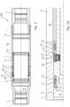
Fig. 1 shows adownhole system 100 for completing awell 2 having atop 51 and a borehole 3 having a borehole pressure PB. Thedownhole system 100 comprises a welltubular metal structure 1 comprising aninside 4 having an inside pressure PI, an opening 5 and anaxial extension 6. Thedownhole system 100 further comprises asliding sleeve 7 movable along the axial extension. Thesliding sleeve 7 is movable between a first position in which thesliding sleeve 7 seals off the opening, as shown inFig. 2A , and a second position in which fluid communication between the borehole 3 and the inside of the welltubular metal structure 1 is allowed, as shown inFig. 2B . The slidingsleeve 7 has an outer face 43 (shown inFig. 6 ) and comprises afirst sealing element 8 arranged on the outer face on one side of theopening 5 and asecond sealing element 9 arranged on the outer face on the other side of theopening 5 in the first position, as shown inFig. 2A . Thefirst sealing element 8 and the second sealing element thus move along with the sliding sleeve when moving between the first and the second position along the inner face 45 (shown inFig. 6 ) of the well tubular metal structure. Thedownhole system 100 further comprises a pressure-reducingmechanism 10, which is arranged adjacent thefirst sealing element 8 for reducing a pressure exerted on thefirst sealing element 8 while moving the slidingsleeve 7 from the first position to the second position. Thefirst sealing element 8 is the sealing element moving past the opening. The second sealing element may not have the pressure-reducing mechanism. - The
downhole system 100 is especially useful when the inside pressure is substantially larger than the borehole pressure, such as when there is a risk of reaching/running through a very low pressure zone, also called experiencing loss of pressure. When the pressure in the borehole is so low, then the pressure difference across the seals of the sliding sleeve is very high. During the movement of the sliding sleeve from the first and closed position to the second and open position, there is a great risk that the sealing element passing the opening is damaged. This is especially the case when the pressure difference is very high as the sealing element is then very energised, i.e. being pushed radially outwards. This is due to the fact that when the first sealing element reaches the opening, the inside pressure, which is very high in relation to the borehole pressure, presses the first sealing element out into the opening, and when the first sealing element then reaches the edge on the other side of the opening, the sealing element is squeezed and damaged. Furthermore, when using an inner string for opening the sliding sleeve, the slidingsleeve 7 is moved at a high speed because of the compression force inherent in the inner string pushing from the top of the well, and as the slidingsleeve 7 starts to move, the inner string starts to un-compress, increasing the speed of the movement. An inner string may be compressed, e.g. 40-50 cm, when pressing onto the slidingsleeve 7, and as the slidingsleeve 7 starts to move, the compression force inherent in the inner string is released, increasing the speed. By having a pressure-reducingmechanism 10, the pressure across thefirst sealing element 8 is reduced before the sealing element reaches the opening, and the pressure exerted on the first sealing element is thus decreased and does not push the sealing element "out of shape", and the first sealing element is de-energised and moves past the opening in its relaxed condition so that the sealing element is not damaged when reaching the edge of the opening. - In
Fig. 2A , the pressure-reducingmechanism 10 is arranged between theopening 5 and thefirst sealing element 8 in the first position. The pressure-reducingmechanism 10 is at least one slit 12 penetrating the welltubular metal structure 1 and extending in theaxial extension 6 from the opening towards thefirst sealing element 8 in the first position. The pressure-reducingmechanism 10 reduces the inside pressure exerted on thefirst sealing element 8 when the slidingsleeve 7 moves from the first position to the second position since when thefirst sealing element 8 passes the slit, the pressure in the welltubular metal structure 1 is equalised with the pressure in the borehole 3 in a venting manner, and as more of the slit is exposed to the inside pressure, the equalising increases. When thefirst sealing element 8 reaches theopening 5, the pressure in the welltubular metal structure 1 is almost equalised with the pressure in the borehole 3, and no force is exerted on the first sealing element, and thefirst sealing element 8 is not damaged due to the pressure difference. The slit forms part of the opening as a "tail", but may also be separate from theopening 5. - In
Fig. 2B , thefirst sealing element 8 and thesecond sealing element 9 are arranged on the same side of theopening 5 in the second position. The welltubular metal structure 1 has arecess 11 in which the slidingsleeve 7 moves between the first position and the second position. Therecess 11 is formed by two well tubularmetal structure parts tubular metal structure 1. - In
Fig. 3 , the pressure-reducingmechanism 10 comprises acheck valve 14 arranged in a through-bore 26 of the sliding sleeve. The pressure-reducing mechanism further comprises asloping part 15, as shown in the enlarged viewFig. 3A , the slopingpart 15 being provided in the welltubular metal structure 1 and in fluid communication with theopening 5. Thecheck valve 14 moves from a closed position to an open position when reaching thesloping part 15, and when the sliding sleeve and the check valve move further, the check valve is opened, allowing fluid from the inside to the borehole. Thecheck valve 14 is shown in its closed position inFig. 3A . As can be seen inFig. 3A , the sloping part forms part of anindentation 16 or may also form part of a groove in the welltubular metal structure 1. The slidingsleeve 7 has athird sealing element 22 arranged between the pressure-reducingmechanism 10 and the opening in the first position, but in another embodiment shown inFig. 4 , the sliding sleeve does not have thethird sealing element 22. Thethird sealing element 22 ofFig. 3A shows the relaxed condition of a sealing element which is not at risk of being damaged when passing an opposing edge 27 (shown inFig. 3 ) of theopening 5. The sealing elements are disclosed as chevron seals, but may also be other suitable sealing elements. - In
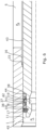
Fig. 5 , thefirst sealing element 8 is arranged between the pressure-reducingmechanism 10 and theopening 5 when the slidingsleeve 7 is in the first position, which arrangement creates an annular volume V between the welltubular metal structure 1, the slidingsleeve 7, thefirst sealing element 8 and the pressure-reducingmechanism 10. The pressure-reducingmechanism 10 is alabyrinth seal 17, which prevents the inside pressure PI in freely equalising with the pressure Pv inside the annular volume V since the fluid has to pass through the labyrinth. As the slidingsleeve 7 moves the first sealing in a position in which the first sealing element partly overlaps the opening, the volume pressure Pv presses slightly onto the other side of thefirst sealing element 8, and the volume increases, but since the volume V is not directly equalised with the inside pressure, the volume pressure drops as a result of the increasing volume, and the pressure exerting onto the first sealing element is reduced accordingly to be significantly smaller than the inside pressure before the first sealing element passes theopening 5. Thefirst sealing element 8 is held in place by means of snap rings 36. -
Fig. 6 shows a cross-sectional view of part of the downhole system inFig. 1 where the slidingsleeve 7 is movable inside the well tubular metal structure and along the axial extension between a first position, in which the sliding sleeve seals off the opening, and a second position, in which fluid communication between the borehole and the inside of the well tubular metal structure is allowed. The sliding sleeve has anouter face 43 having at least onegroove 44, and the outer face faces aninner face 45 of the well tubular metal structure, thefirst sealing element 8 being arranged in the groove on one side of the opening, and thesecond sealing element 9 being arranged on the other side of the opening in the first position. Thefirst sealing element 8 is arranged between the pressure-reducingmechanism 10 and the opening, and the pressure-reducingmechanism 10 is alabyrinth seal 17 for reducing a pressure exerted on the first sealing element while moving the sliding sleeve from the first position to the second position. The sealing elements and the pressure-reducingmechanism 10 are arranged on the sliding sleeve and slide along with the sliding sleeve. In this way, the sealing elements are not left behind being exposed to well fluid as they would be in prior art solutions, where the sealing elements are arranged in the well tubular metal structure, and where the sliding sleeve moves and no longer holds them squeezed in place between the sliding sleeve and the well tubular metal structure. Furthermore, the sealingelements - The
first sealing element 8 ofFig. 6 comprises afirst element part 37 and twosecond element parts 38, where thesecond element part 38 is made of a material more rigid than that of thefirst element part 37 so that the second element part is configured to wipe off the inner face of the well tubular structure when the sliding sleeve moves the first sealing element past the opening and into a position between the well tubular metal structure and the sliding sleeve. - The
second element part 38 may be of polyetheretherketon (PEEK), and thefirst element part 37 may be of a polymer more ductile than that of PEEK. Thefirst element part 37 has anelement groove 42 facing theouter face 43 of the sliding sleeve and forming a cavity therebetween. Thefirst sealing element 8 further comprises athird element part 41 arranged in theelement groove 42 configured to spring load or energise thethird element part 41. Thethird element part 41 may be an O-ring or a material suitable for providing the spring loading or energising of thethird element part 41. - Even though not shown in
Fig. 6 , thesecond sealing element 9 may have the same configuration as the first sealing element. - In
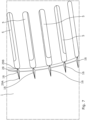
Fig. 7 , part of the well tubular metal structure is seen from within, showing theopenings 5 and theindentation 16 at the edge of the opening closest to the first sealing element when in the first position. Theindentation 16 begins with a taperingpart 29A and ends in asecond part 29B and in between has abroader section 28. The tapering part 29 tapers from themiddle section 28 away from the opening. When the first sealing element slides past theindentation 16, the sealing element first passes the taperingpart 29A so that the pressure equalising occurs more slowly than if the opening was not "prolonged" with the indentation. If the indentation is arranged on the sloping part, the tapering part 29 tapers from themiddle section 28 away from the opening along the sloping part. The indentation may also be arranged without the sloping part in the inner face of the well tubular metal structure. - By having the
labyrinth seal 17, thefirst sealing element 8 is not exposed to the full inside pressure and thus not exposed to the full pressure difference between the borehole pressure PB and the inside pressure PI, but the inside pressure PI is restricted by the labyrinth seal. By having thelabyrinth seal 17 and arranging the first sealing element between thelabyrinth seal 17 and theopening 5 and the indentation, the first sealing element is not damaged when opening the sliding sleeve even when there is a high pressure difference between the borehole pressure PB and the inside pressure PI. By further having thefirst sealing element 8 and the labyrinth seal arranged on the outer face of the sliding sleeve and moving along with the sliding sleeve, the first sealing element is arranged to be pressing against the outer face of the sliding sleeve. In prior art solutions where the seals are arranged in the inner face of the well tubular metal structure and when passing a groove in the outer face of the sliding sleeve, the seals bulge unintentionally inwards and are sligthly offset from their indented position and thus get damaged by moving past such groove. This is not the case with the present invention as the sealing elements are arranged to be stretching around the outer face of the sliding sleeve, and thus a pre-tension of the sealing elements is provided so that the sealing elements press on the outer face and do not become slightly misplaced when passsing the indentation. - In
Fig. 8 , thefirst sealing element 8 comprises thefirst element part 37 and thesecond element parts 38, and thethird element part 41 for energising thefirst element part 37. Furthermore, thefirst sealing element 8 comprises twofourth element parts 39 which are C-shaped so as to provide an even better seal, and thefourth element 39 closest to theopening 5 will also provide a wiping effect when the sealing element has passed the opening and is moved along the inner face of the well tubular metal structure on the other side of the opening. In between the otherfourth element 39 and one of thesecond element parts 38, asecond labyrinth seal 17 is provided so that the fluid is restricted twice before passing thefirst element part 37 and thesecond element parts 38. - As shown in
Fig. 2B , the well tubular metal structure comprises more than one opening provided around the circumference of the welltubular metal structure 1. Even though not shown, the welltubular metal structure 1 comprises more than one opening provided at a distance from each other along theaxial extension 11, a slidingsleeve 7 moving opposite each opening. - In
Fig. 1 , thedownhole system 100 further comprises an engagingelement 18 for engaging a profile 19 (shown inFig. 3A ) in the slidingsleeve 7 for moving the slidingsleeve 7 between the first position and the second position. Theengaging elements 18 are parts of anintervention tool 20, but may also be part of an inner welltubular metal structure 21 if that is used to open or close the sliding sleeves. - The
downhole system 100 further comprises threeannular barriers 30, each having atubular part 31 mounted as part of the welltubular metal structure 1. Thetubular part 31 is surrounded by anexpandable metal sleeve 32, which is expanded by means of pressurised fluid from the inside of the welltubular metal structure 1 through avalve assembly 34 into anannular space 35 between the tubular part and the expandable metal sleeve to abut the wall of the borehole as shown in the bottom part of the well tubular metal structure ofFig. 1 , or to abut the upper well tubular metal structure as shown in the top of the welltubular metal structure 1. The first annular barrier and a second annular barrier abutting the wall of the borehole together isolate aproduction zone 101 between them, and when the sliding sleeve is in its second position, the reservoir fluid is allowed to flow into the welltubular metal structure 1 through theopening 5 and past the sliding sleeve and further up the inner string. The inner string may extend all the way to the bottom 54 of the welltubular metal structure 1. Even though not shown, the downhole system may further comprise a plurality ofopenings 5 arranged at a distance along theaxial extension 6 and a plurality of sliding sleeves so that each sliding sleeve is arranged opposite one of the openings. - The intervention tool may comprise a stroking tool which is a tool providing an axial force. The stroking tool comprises an electric motor for driving a pump. The pump pumps fluid into a piston housing to move a piston acting therein. The piston is arranged on the stroker shaft. The pump may pump fluid into the piston housing on one side and simultaneously suck fluid out on the other side of the piston.
- By fluid, reservoir fluid or well fluid is meant any kind of fluid that may be present in oil or gas wells downhole, such as natural gas, oil, oil mud, crude oil, water, etc. By gas is meant any kind of gas composition present in a well, completion or open hole, and by oil is meant any kind of oil composition, such as crude oil, an oil-containing fluid, etc. Gas, oil and water fluids may thus all comprise other elements or substances than gas, oil and/or water, respectively.
- By a casing or well tubular metal structure is meant any kind of pipe, tubing, tubular, liner, string, etc., used downhole in relation to oil or natural gas production.
- In the event that the intervention tool is not submergible all the way into the casing, a downhole tractor can be used to push the tool all the way into position in the well. The downhole tractor may have projectable arms having wheels, wherein the wheels contact the inner surface of the casing for propelling the tractor and the tool forwards in the casing. A downhole tractor is any kind of driving tool capable of pushing or pulling tools in a well downhole, such as a Well Tractor®.
- Although the invention has been described above in connection with preferred embodiments of the invention, it will be evident to a person skilled in the art that several modifications are conceivable without departing from the invention as defined by the following claims.
Claims (15)
- A downhole system (100) for completing a well (2), comprising:- a well tubular metal structure (1) arranged in a borehole (3) having a borehole pressure (PB), the well tubular metal structure comprising an inner face (45) and an inside (4) having an inside pressure (PI), an opening (5) and an axial extension (6), and- a sliding sleeve (7) having an outer face (43) and being movable inside the well tubular metal structure and along the axial extension between a first position in which the sliding sleeve seals off the opening and a second position in which fluid communication between the borehole and the inside of the well tubular metal structure is allowed, characterised in thatthe sliding sleeve comprises a first sealing element (8) arranged on the outer face on one side of the opening and a second sealing element (9) arranged on the outer face on the other side of the opening in the first position,wherein a pressure-reducing mechanism (10) is arranged in relation to the first sealing element for reducing a pressure exerted on the first sealing element while moving the sliding sleeve from the first position to the second position, and wherein the pressure-reducing mechanism is a labyrinth seal (17).
- A downhole system according to claim 1, wherein the sliding sleeve has the outer face having at least two grooves and facing the inner face of the well tubular metal structure, the first sealing element being arranged in one of the grooves, and the second sealing element being arranged in the other groove.
- A downhole system according to claim 1 or 2, wherein an inner diameter of the sealing elements is less than an outer diameter of a part of the outer face of the sliding sleeve so as to provide the sealing elements with pre-tension when arranged on that part of the outer face.
- A downhole system according to any of the preceding claims, wherein a sloping part forms part of an indentation (16) or a groove in the well tubular metal structure.
- A downhole system according to claim 4, wherein the indentation ends in the opening.
- A downhole system according to claim 5, wherein the indentation has a tapering part (29A) furthest away from the opening.
- A downhole system according to any of the preceding claims, wherein the well tubular metal structure has a recess (11) in which the sliding sleeve moves between the first position and the second position.
- A downhole system according to any of claims 1-3, wherein the pressure-reducing mechanism is arranged between the opening and the first sealing element in the first position.
- A downhole system according to any of the preceding claims, wherein at least the first sealing element comprises a first element part (37) and a second element part (38), where the second element part is made of a material more rigid than that of the first element part.
- A downhole system according to claim 4, wherein the pressure-reducing mechanism is at least one slit (12) penetrating the well tubular metal structure and extending along the axial extension from the opening towards the first sealing element in the first position.
- A downhole system according to claim 4, wherein the pressure-reducing mechanism comprises a check valve (14) arranged in the sliding sleeve and a sloping part (15) being provided in the well tubular metal structure and being in fluid communication with the opening so that the check valve moves from a closed position to an open position when the check valve is opposite the sloping part, allowing fluid to flow from the inside to the borehole.
- A downhole system according to any of claims 1-3, wherein the first sealing element is arranged between the pressure-reducing mechanism and the opening in the first position, which creates an annular volume (V) between the well tubular metal structure, the sliding sleeve, the first sealing element and the pressure-reducing mechanism.
- A downhole system according to any of the preceding claims, further comprising an engaging element (18) for engaging a profile (19) in the sliding sleeve and for moving the sliding sleeve between the first position and the second position, the engaging element being part of an intervention tool (20) or an inner well tubular metal structure (21).
- A downhole system according to any of the preceding claims, further comprising a third sealing element (22) arranged between the pressure-reducing mechanism and the opening in the first position.
- A downhole system according to any of the preceding claims, further comprising an annular barrier (30) having a tubular part (31) to be mounted as part of the well tubular metal structure, the tubular part being surrounded by an expandable metal sleeve (32) configured to be expanded by means of pressurised fluid from the inside of the well tubular metal structure through a valve assembly (34) into an annular space (35) between the tubular part and the expandable metal sleeve.
Applications Claiming Priority (2)
| Application Number | Priority Date | Filing Date | Title |
|---|---|---|---|
| EP18155899.0A EP3524773A1 (en) | 2018-02-08 | 2018-02-08 | Downhole system with sliding sleeve |
| PCT/EP2019/053062 WO2019154940A1 (en) | 2018-02-08 | 2019-02-07 | Downhole system with sliding sleeve |
Publications (2)
| Publication Number | Publication Date |
|---|---|
| EP3749835A1 EP3749835A1 (en) | 2020-12-16 |
| EP3749835B1 true EP3749835B1 (en) | 2024-03-13 |
Family
ID=61189253
Family Applications (2)
| Application Number | Title | Priority Date | Filing Date |
|---|---|---|---|
| EP18155899.0A Withdrawn EP3524773A1 (en) | 2018-02-08 | 2018-02-08 | Downhole system with sliding sleeve |
| EP19704306.0A Active EP3749835B1 (en) | 2018-02-08 | 2019-02-07 | Downhole system with sliding sleeve |
Family Applications Before (1)
| Application Number | Title | Priority Date | Filing Date |
|---|---|---|---|
| EP18155899.0A Withdrawn EP3524773A1 (en) | 2018-02-08 | 2018-02-08 | Downhole system with sliding sleeve |
Country Status (8)
| Country | Link |
|---|---|
| US (1) | US11002103B2 (en) |
| EP (2) | EP3524773A1 (en) |
| CN (1) | CN111655965A (en) |
| AU (1) | AU2019219113B2 (en) |
| BR (1) | BR112020015207A2 (en) |
| CA (1) | CA3090031A1 (en) |
| MX (1) | MX2020007815A (en) |
| WO (1) | WO2019154940A1 (en) |
Families Citing this family (5)
| Publication number | Priority date | Publication date | Assignee | Title |
|---|---|---|---|---|
| GB201909398D0 (en) * | 2019-06-29 | 2019-08-14 | Ackroyd Warren Matthew | Duel isolation bore seal system |
| US11746620B2 (en) * | 2021-06-24 | 2023-09-05 | Baker Hughes Oilfield Operations Llc | Injection valve, system and method |
| GB2621085A (en) * | 2021-07-13 | 2024-01-31 | Halliburton Energy Services Inc | Dampening the actuation speed of a downhole tool |
| US11891866B2 (en) | 2021-07-13 | 2024-02-06 | Halliburton Energy Services, Inc. | Dampening the actuation speed of a downhole tool |
| US11885196B1 (en) | 2022-10-24 | 2024-01-30 | Cnpc Usa Corporation | Retrievable packer with slotted sleeve release |
Family Cites Families (7)
| Publication number | Priority date | Publication date | Assignee | Title |
|---|---|---|---|---|
| US3211232A (en) * | 1961-03-31 | 1965-10-12 | Otis Eng Co | Pressure operated sleeve valve and operator |
| US5156220A (en) * | 1990-08-27 | 1992-10-20 | Baker Hughes Incorporated | Well tool with sealing means |
| US7363981B2 (en) * | 2003-12-30 | 2008-04-29 | Weatherford/Lamb, Inc. | Seal stack for sliding sleeve |
| US7191843B2 (en) * | 2004-06-24 | 2007-03-20 | Petroquip Energy Services, Inc. | Valve apparatus with seal assembly |
| GB0504055D0 (en) * | 2005-02-26 | 2005-04-06 | Red Spider Technology Ltd | Valve |
| BR112016011906B1 (en) * | 2013-12-31 | 2021-07-06 | Halliburton Energy Services, Inc | safety valve, and, method of actuating a safety valve |
| US10041331B2 (en) * | 2015-02-18 | 2018-08-07 | Halliburton Energy Services, Inc. | Shifting tool assembly that facilitates controlled pressure equalization |
-
2018
- 2018-02-08 EP EP18155899.0A patent/EP3524773A1/en not_active Withdrawn
-
2019
- 2019-02-07 US US16/270,035 patent/US11002103B2/en active Active
- 2019-02-07 AU AU2019219113A patent/AU2019219113B2/en active Active
- 2019-02-07 CN CN201980009950.1A patent/CN111655965A/en active Pending
- 2019-02-07 BR BR112020015207-2A patent/BR112020015207A2/en unknown
- 2019-02-07 CA CA3090031A patent/CA3090031A1/en not_active Abandoned
- 2019-02-07 MX MX2020007815A patent/MX2020007815A/en unknown
- 2019-02-07 EP EP19704306.0A patent/EP3749835B1/en active Active
- 2019-02-07 WO PCT/EP2019/053062 patent/WO2019154940A1/en unknown
Also Published As
| Publication number | Publication date |
|---|---|
| RU2020128286A (en) | 2022-03-09 |
| CN111655965A (en) | 2020-09-11 |
| CA3090031A1 (en) | 2019-08-15 |
| US20190242211A1 (en) | 2019-08-08 |
| WO2019154940A1 (en) | 2019-08-15 |
| US11002103B2 (en) | 2021-05-11 |
| EP3749835A1 (en) | 2020-12-16 |
| EP3524773A1 (en) | 2019-08-14 |
| MX2020007815A (en) | 2020-09-25 |
| AU2019219113B2 (en) | 2021-09-09 |
| AU2019219113A1 (en) | 2020-09-17 |
| BR112020015207A2 (en) | 2021-01-26 |
Similar Documents
| Publication | Publication Date | Title |
|---|---|---|
| EP3749835B1 (en) | Downhole system with sliding sleeve | |
| US20100051293A1 (en) | Downhole tool with load diverting system and method | |
| US5611547A (en) | Elongated seal assembly for sealing well tubing-to liner annulus | |
| EP3469184B1 (en) | Downhole straddle assembly | |
| US20160376868A1 (en) | Downhole packer tool | |
| US20030019629A1 (en) | Sand control seal for subsurface safety valve | |
| US7896090B2 (en) | Stroking tool using at least one packer cup | |
| AU2002320274A1 (en) | Sand control seal for subsurface safety valve | |
| RU2804463C2 (en) | Sliding sleeve downhole system | |
| AU2011293599B2 (en) | Pump through circulating and or safety circulating valve | |
| AU2017281259B2 (en) | Method and apparatus to utilize a metal to metal seal | |
| AU2019394726B2 (en) | Downhole tool with a long projecting extension | |
| US8727025B2 (en) | Downhole tool seal arrangement and method of sealing a downhole tubular | |
| CA2486507C (en) | Double acting fluid actuated telescopic cylinder | |
| AU2008200288B2 (en) | Sand control seal for subsurface safety valve | |
| GB2312227A (en) | A seal for a wellbore annulus | |
| GB2283518A (en) | High pressure seal | |
| GB2410968A (en) | Seal assembly for insert safety valve |
Legal Events
| Date | Code | Title | Description |
|---|---|---|---|
| STAA | Information on the status of an ep patent application or granted ep patent |
Free format text: STATUS: UNKNOWN |
|
| STAA | Information on the status of an ep patent application or granted ep patent |
Free format text: STATUS: THE INTERNATIONAL PUBLICATION HAS BEEN MADE |
|
| PUAI | Public reference made under article 153(3) epc to a published international application that has entered the european phase |
Free format text: ORIGINAL CODE: 0009012 |
|
| STAA | Information on the status of an ep patent application or granted ep patent |
Free format text: STATUS: REQUEST FOR EXAMINATION WAS MADE |
|
| 17P | Request for examination filed |
Effective date: 20200826 |
|
| AK | Designated contracting states |
Kind code of ref document: A1 Designated state(s): AL AT BE BG CH CY CZ DE DK EE ES FI FR GB GR HR HU IE IS IT LI LT LU LV MC MK MT NL NO PL PT RO RS SE SI SK SM TR |
|
| AX | Request for extension of the european patent |
Extension state: BA ME |
|
| DAV | Request for validation of the european patent (deleted) | ||
| DAX | Request for extension of the european patent (deleted) | ||
| STAA | Information on the status of an ep patent application or granted ep patent |
Free format text: STATUS: EXAMINATION IS IN PROGRESS |
|
| 17Q | First examination report despatched |
Effective date: 20220928 |
|
| REG | Reference to a national code |
Ref country code: NO Ref legal event code: TC |
|
| GRAP | Despatch of communication of intention to grant a patent |
Free format text: ORIGINAL CODE: EPIDOSNIGR1 |
|
| STAA | Information on the status of an ep patent application or granted ep patent |
Free format text: STATUS: GRANT OF PATENT IS INTENDED |
|
| INTG | Intention to grant announced |
Effective date: 20230511 |
|
| P01 | Opt-out of the competence of the unified patent court (upc) registered |
Effective date: 20230523 |
|
| GRAJ | Information related to disapproval of communication of intention to grant by the applicant or resumption of examination proceedings by the epo deleted |
Free format text: ORIGINAL CODE: EPIDOSDIGR1 |
|
| STAA | Information on the status of an ep patent application or granted ep patent |
Free format text: STATUS: EXAMINATION IS IN PROGRESS |
|
| GRAP | Despatch of communication of intention to grant a patent |
Free format text: ORIGINAL CODE: EPIDOSNIGR1 |
|
| STAA | Information on the status of an ep patent application or granted ep patent |
Free format text: STATUS: GRANT OF PATENT IS INTENDED |
|
| INTC | Intention to grant announced (deleted) | ||
| INTG | Intention to grant announced |
Effective date: 20230922 |
|
| GRAS | Grant fee paid |
Free format text: ORIGINAL CODE: EPIDOSNIGR3 |
|
| GRAA | (expected) grant |
Free format text: ORIGINAL CODE: 0009210 |
|
| STAA | Information on the status of an ep patent application or granted ep patent |
Free format text: STATUS: THE PATENT HAS BEEN GRANTED |
|
| AK | Designated contracting states |
Kind code of ref document: B1 Designated state(s): AL AT BE BG CH CY CZ DE DK EE ES FI FR GB GR HR HU IE IS IT LI LT LU LV MC MK MT NL NO PL PT RO RS SE SI SK SM TR |
|
| REG | Reference to a national code |
Ref country code: GB Ref legal event code: FG4D |
|
| REG | Reference to a national code |
Ref country code: CH Ref legal event code: EP |
|
| REG | Reference to a national code |
Ref country code: DE Ref legal event code: R096 Ref document number: 602019048165 Country of ref document: DE |