EP3749508B1 - Attachment for sealing seams - Google Patents
Attachment for sealing seams Download PDFInfo
- Publication number
- EP3749508B1 EP3749508B1 EP19748424.9A EP19748424A EP3749508B1 EP 3749508 B1 EP3749508 B1 EP 3749508B1 EP 19748424 A EP19748424 A EP 19748424A EP 3749508 B1 EP3749508 B1 EP 3749508B1
- Authority
- EP
- European Patent Office
- Prior art keywords
- rollers
- attachment
- polymer
- fabric members
- seam
- Prior art date
- Legal status (The legal status is an assumption and is not a legal conclusion. Google has not performed a legal analysis and makes no representation as to the accuracy of the status listed.)
- Active
Links
Images




Classifications
-
- D—TEXTILES; PAPER
- D05—SEWING; EMBROIDERING; TUFTING
- D05B—SEWING
- D05B17/00—Sewing machines for concurrently making thread and welded seams
-
- D—TEXTILES; PAPER
- D05—SEWING; EMBROIDERING; TUFTING
- D05B—SEWING
- D05B1/00—General types of sewing apparatus or machines without mechanism for lateral movement of the needle or the work or both
- D05B1/26—General types of sewing apparatus or machines without mechanism for lateral movement of the needle or the work or both for making fluid-tight seams
-
- D—TEXTILES; PAPER
- D05—SEWING; EMBROIDERING; TUFTING
- D05B—SEWING
- D05B19/00—Program-controlled sewing machines
- D05B19/02—Sewing machines having electronic memory or microprocessor control unit
- D05B19/12—Sewing machines having electronic memory or microprocessor control unit characterised by control of operation of machine
- D05B19/16—Control of workpiece movement, e.g. modulation of travel of feed dog
-
- D—TEXTILES; PAPER
- D05—SEWING; EMBROIDERING; TUFTING
- D05B—SEWING
- D05B35/00—Work-feeding or -handling elements not otherwise provided for
- D05B35/06—Work-feeding or -handling elements not otherwise provided for for attaching bands, ribbons, strips, or tapes or for binding
-
- D—TEXTILES; PAPER
- D05—SEWING; EMBROIDERING; TUFTING
- D05D—INDEXING SCHEME ASSOCIATED WITH SUBCLASSES D05B AND D05C, RELATING TO SEWING, EMBROIDERING AND TUFTING
- D05D2209/00—Use of special materials
- D05D2209/10—Particular use of plastics
-
- D—TEXTILES; PAPER
- D05—SEWING; EMBROIDERING; TUFTING
- D05D—INDEXING SCHEME ASSOCIATED WITH SUBCLASSES D05B AND D05C, RELATING TO SEWING, EMBROIDERING AND TUFTING
- D05D2305/00—Operations on the work before or after sewing
- D05D2305/22—Physico-chemical treatments
- D05D2305/26—Heating
Definitions
- This invention relates to an attachment for an existing sewing machine, including an improved mechanism for pulling fabric members to be sewn to one another using thread comprising a thermoplastic polymer, together with a strip of the same or a different thermoplastic polymer, through a sewing machine while applying heat and pressure thereto, so as to sew the seam and melt the polymer to seal the seam in a single operation.
- the most prevalent method of sealing a sewn seam is to apply a wide tape of thermoplastic polymer with an adhesive layer over a previously sewn seam.
- the garment or other object is supplied to a machine provided with a pair of opposed rollers.
- a polymer substrate on the order of one inch wide with adhesive on one side thereof is heated by a stream of hot air, to activate the adhesive, and is then urged against the seam by the rollers so as to be adhered to the fabric members over the seam as the tape cools, covering the seam.
- This method of seam sealing has many drawbacks, perhaps most notably that it requires the seam to be sealed in a separate operation from the sewing of the seam. Clearly if the seam could be sewn and sealed in a single operation substantial economies would be realized in terms of reduced labor requirements, reduced floor space requirements, and reduced equipment costs.
- the application of the polymer tape also stiffens the seam in ways that can be uncomfortable and restrict the wearer's motion in the case of garments, and adds additional weight.
- Ferreiro US patent application 13/594,415 filed August 24, 2012 claiming priority from provisional application 61/575,602, filed August 24, 2011 , and published as publication No. 2013/0048219 , and in copending continuation application 14/999,320, to issue February 13, 2018 as patent 9,889,598 .
- the Ferreiro applications describe a method for forming a waterproof seam while sewing the seam by employing a thread comprising a quantity of thermoplastic polymer and heating the seam while applying pressure, melting the polymer so as to fill the punctures.
- a strip of thermoplastic polymer can also be inserted between the fabric members during the sewing step and be bonded to the fabric members in the same step of applying heat and pressure, sealing the seam between the thread punctures.
- US patent US 5003902 A discloses a liquid proof seam construction.
- a double needle flat-felled seam is constructed having a melt adhesive polymer film disposed within the seam.
- the seam is then passed through a hot air/pressure device which melts the film and compresses the seam.
- This forms a liquid, e.g. waterproof, bond between adjacent layers of material and also fills up any area around the stitching formed by needle holes.
- Japanese patent JP 2004 208824 A discloses a method of producing a waterproof sewn product, wherein a waterproofed cloth is sewn into a flat felled seam.
- the method comprises: the first step of arranging a thermoplastic polyurethane hot melt film at a part which is between the lapped waterproofed clothes and which becomes a margin part for a seam; the second step of sewing up the waterproofed clothes with each other; and the third step of heating/pressurizing the margin part for the seam of the thermoplastic polyurethane hot melt film for thermally fusing the film.
- the present application relates to improvements in the mechanism and process described in the Ferreiro application, essentially taking it from the "proof-of-concept" status described therein to a fully commercialized device that can be attached readily to various commercial sewing machines.
- One particular improvement relates to the means of application of heat and pressure to seal the seam as it is being sewn.
- One aspect of the present invention is to replace the heated roller opposed to a heated plate or to another heated roller of the Ferriero application with a series of driven heated rollers, typically three, opposed to pairs of heated idler rollers, with a belt disposed over the heated idler rollers, such that the belt urges the fabric members to be joined against the heated driven rollers. This ensures that the fabric members are in contact with the heated driven rollers long enough to ensure effective melting of the polymer, and thereby ensuring that the seam is effectively sealed.
- Another improvement provided according to the present invention is driving the downstream roller slightly faster than the upstream rollers, slightly stretching the fabric while heating the seam, to ensure that the seam remains well-formed after the polymer cools and hardens.
- a typical commercial sewing machine 10 comprises an upright column 12, in which runs a drive belt from a motor (not shown) disposed under a table 14, the motor being controlled by a foot switch 20 or the like, a transverse arm 16, a sewing mechanism 18, including a needle 19 and a presser foot 21 (see Fig. 2 ), a lever 13 for lifting the foot 21 out of engagement with fabric members 7 and 9 to be sewn to one another, and a flywheel 22.
- an attachment 24 is attached to the sewing machine 10 by removing a cover plate (not shown) and assembling the attachment 24 in place of the cover plate.
- the details of this replacement of the cover plate by the attachment will of course vary somewhat from machine to machine; in each case, the attachment is designed so that the rollers (discussed further below) are disposed directly behind needle 19.
- a reel 23 dispensing a strip 25 of an adhesive thermoplastic polymer, and a feeder assembly 27 for directing the polymer strip 25 into the seam being sewn.
- the strip employed according to the invention may typically be 1/8 - 1 ⁇ 4 inch wide by 0.010- 0.020 inches thick, 0.014 inches being preferred.
- the feeder assembly 27 may be provided with a hot air duct and nozzle, to preheat the polymer strip 25 and activate its adhesive properties prior to its being sewn into the seam.
- Fig. 8 shows details of the air system used to preheat the polymer strip 25.
- an electronic control unit 26 which may comprise a touch screen 28 for receiving user input concerning the parameters necessary to control the process of sealing the seam, such as the temperature of heated rollers that apply heat and pressure to the seam to melt the polymer and seal the seam, and a microprocessor 29 (indicated as a component of computer device 26 as "MP") for receiving these user inputs and other data, and for providing control signals to the various components of the attachment.
- Fig. 7 shows a block diagram of this circuitry.
- a magnet 30 (see Fig. 6 ), mechanically affixed to the flywheel 22, and a Hall-effect sensor 32, likewise mechanically affixed to the upright column 12.
- the sewing machine 10 advances the fabric members 7 and 9 to be sewn together incrementally, by the desired length of the stitch, and the presser foot 21 then holds them in place, so that the needle 19 can puncture the fabric members while stationary.
- flywheel 22 is rotated intermittently.
- the attachment of the invention comprises heated rollers 40, 42, and 44 (see Fig. 4 ) that are driven to pull the fabric members through the attachment while applying heat and pressure to the seam so as to melt the polymer and seal the seam.
- the driven rollers In order to function properly, the driven rollers must cease pulling on the fabric members during the stitching process.
- HE a signal that is provided to the microprocessor 29 to control two motors 34 and 36 via signals M1 and M2 ( Figs. 1 and 7 ) that drive the rollers.
- Signal HE is thus used to synchronize the operation of the rollers to the remainder of the sewing machine, so as to avoid distorting the fabric.
- the circuitry connecting the microprocessor 29 to the various components providing and receiving the signals noted is not shown in Fig. 1 , for clarity of the drawing, but will be readily understood and easily implemented by those of skill in the art. As above, Fig. 7 shows a schematic diagram of this circuitry.
- operation of the sewing machine is controlled by a foot pedal 20 or the like, such as a knee- or hand-operated switch operated by an operator.
- a control signal SW from foot pedal 20 is provided to microprocessor 29 which in turn provides a control signal AC to an air cylinder 48.
- the assembly of rollers 40, 42, and 44 and of motors 34 and 36 is carried by air cylinder 48 and is withdrawn upwardly, out of engagement with the fabric members, when operation of the sewing machine 10 is stopped by the operator. At the same time the stream of hot air preheating the strip of polymer 25 is shut off.
- the signals provided by microprocessor 29 also include three control signals H1, H2 and H3 provided to rollers 40, 42 and 44 respectively, to control their surface temperature and thereby the amount of heat applied to the seam. Control of the surface temperature of these rollers is clearly important to obtaining adequate melting of the polymer of the thread and strip to provide good sealing without scorching or burning the fabric.
- the surface temperature of the rollers can be measured directly using infrared sensors, if such can be found that are sufficiently durable, or the temperature can be controlled indirectly using a feedback loop.
- the rollers can be heated using internal cartridge heaters 51. See Fig. 5 . Idler rollers 50 (discussed further below) are likewise heated.
- the cartridge heaters 51 in order that electrical connections can be made to the cartridge heaters 51, they must be stationary, while driven rollers 40, 42 and 46 and idler rollers 50 must rotate freely over heaters 51.
- the heaters 51 are designed to expand when current is applied, typically so as to fit snugly into a hole bored in a volume of material to be heated.
- the cartridge heaters can be disposed in sections 53 of steel tubing, while the rollers may be made of aluminum, bored to be a sliding fit over the steel tubes, and assembled with a small quantity of heat-conducting grease there- between.
- the greater coefficient of thermal expansion of aluminum as compared to that of steel will prevent the heating of the cartridge heaters 51 from interfering with rotation of the rollers.
- the temperatures of the surfaces of the rollers can be measured directly using infrared sensors, if suitably durable components can be found.
- thermocouples can be provided to measure the temperatures of the cartridge heaters 51, and this data used in a well-known proportional-integral-derivative (PID) feedback loop to control the temperatures of the surfaces of the rollers.
- PID proportional-integral-derivative
- Fig. 4 shows an end view of the assembly of driven heated rollers 40, 42 and 44, heated idler rollers 50, and belt 52 in detail;
- Figs. 2 , 3 , 5 and 6 show further features provided according to the invention.
- Rollers 50 are carried by a chassis 56 that is assembled to the sewing machine 10, typically by attachment to the hinge (not shown) conventionally provided to allow the sewing machine to be pivoted out of its' “nest” in the sewing machine table 14.
- Fig. 4 is effectively taken from inside chassis 56, so as to show the ends of rollers 50.
- Chassis 56 has an inclined leading surface 56a (see Fig.
- Chassis 56 is preferably spaced from the sewing machine 10 by insulating spacers (not shown) to allow air to pass there between and avoid overheating the sewing machine 10.
- a continuous belt 52 fits over rollers 50 and moves together with the fabric members 7 and 9 to be sewn, which are indicated by a heavy broken line 58 in Fig. 4 .
- Belt 52 rides over a final, unheated roller 60, and is tensioned by springs 54 on either side of the chassis 56, biasing roller 60 (leftwardly in the view of Fig. 4 ) toward the "downstream" end of chassis 56; the degree of tension in belt 52 may be adjusted by provision of differing springs 54, or by adjustment of the preload provided.
- the biasing roller 60 is mounted in a slot 56b in chassis 56, to allow it to move to adjust the tension in belt 52.
- the fabric members 7 and 9 to be bonded to one another are urged by belt 52 into engagement with rollers 40, 42, and 44 along a lower portion of the circumference of each of rollers 40, 42, and 44 between the opposed pairs of idler rollers 50, ensuring good heat transfer between rollers 40, 42, and 46 on the upper side, to the fabric members indicated at 58.
- belt 52 can be made of a composite of fiberglass cloth coated by one or more layers of Teflon ® material.
- the extension of the heat transfer area provided by provision of the belt 52 is highly beneficial in ensuring sufficient heat transfer to effectively melt the polymer materials of the thread 17 and strip 25, and thereby effectively sealing the seam.
- Belt 52 also prevents the fabric members from being tangled in rollers 50.
- the axes of driven rollers 40, 42, and 44 are coplanar, as are those of the idler rollers 50, as illustrated by Fig. 4 .
- the spring tension provided to unheated idler roller 60 by springs 54 will cause roller 60 to move leftwardly, so that belt 52 will take a straight-line path over the upper surfaces of idler rollers 50.
- the driven rollers 40, 42, and 44 are brought back downwardly as sewing resumes, the belt 52 will be forced away from the straight-line path so as to conform to the lower circumferential surfaces of rollers 40, 42, and 44 between the respective pairs of idler rollers 50, taking the form shown in Fig. 4 , while the springs 54 allow the unheated idler roller 60 to move rightwardly in the view of Fig. 4 .
- the heat and pressure provided by the rollers melts the preheated polymer strip 25 and squeezes it laterally, filling the space between the fabric members 7 and 9.
- the practice of the invention will also involve the use of the polymer-laden thread 17 of the Ferriero applications, so that the polymer of the thread 17 is melted at the same time, filling the punctures left by the needle.
- the polymer strip 25 may be avoided and only the thread 17 used.
- the polymers applied to the thread 17 and that of strip 25 may be the same or may differ. As of the filing of this application, experimentation is being performed to identify the optimal materials for these purposes. They may be as disclosed in the Ferreiro application, that is, thermoplastic polyurethane, or possibly materials selected from the group including nylon, polyester, polyolefin and vinyl, and mixtures and combinations thereof. It will be appreciated that these materials have good adhesive properties, so that the seam is strengthened as well as sealed by practice of the invention. The materials used in the prior art seam sealing processes may also be used.
- the polymer is applied to the thread in a bath of molten polymer, so that the polymer is absorbed into the yarns of the thread, followed by passage through a die or the like, squeezing out extra polymer, so the final polymer content of the thread is 2 - 6 % by weight, as in the Ferreiro applications.
- the "upstream" rollers 42 and 44 are driven by motor 36 by way of a first belt 60, while the “downstream” roller 40 is driven separately by motor 34 by way of a second belt 62.
- the motors 34 and 36 are operated responsive to signals M1 and M2 ( Figs. 1 and 7 ) respectively, so that the rollers can be driven at different speeds as desired.
- the downstream roller 40 is driven at a slightly higher speed than the upstream rollers 42 and 44, so as to exert tension on the assembly of fabric members while the polymer is being melted and the seam compressed, ensuring that the seam is properly formed.
- driven rollers 40, 42, and 44 are knurled as illustrated, so as to ensure adequate friction between these surfaces and the fabric members 7 and 9. A coating is applied to produce a non-stick surface.
- An operator-controlled cutter (not shown) may be provided between the rollers 40, 42, and 44 and presser foot 21, to cut the polymer strip 25 at the end of the seam.
- Rollers 40, 42, and 44 are carried by a frame 64 ( Fig. 2 ) that is pivoted transversely at 66 with respect to the moving actuator 68 of air cylinder 48. This pivoting allows the rollers to remain in contact with the fabric members 7 and 9 despite some degree of irregularity in the thickness of the fabric members, such as where several fabric members cross one another.
- the rollers 40, 42, 44 may also be carried on individual suspensions, spring-biased downwardly with respect to frame 64, for similar reasons.
- Fig. 7 is a schematic diagram of the electrical circuitry provided according to the invention.
- an electronic control unit (ECU) 80 which may comprise microprocessor 29 and associated supporting components, including a user interface such as touch screen 26, receives sensor inputs and provides control signals through appropriate interface circuit boards.
- a set of temperature sensors 70 for the lower roller assembly that is, idler rollers 50
- a set of temperature sensors 72 for the driven rollers 40, 42, and 44 and an air process temperature sensor 73 for measuring the temperature of the stream of air preheating the polymer tape 25, each provide temperature data to a sensor input board 74.
- Sensor input board 74 then performs simple operations on the data, for example, analog-to-digital conversion, and provides the results to ECU 80 as indicated at 76.
- the signals responsive to roller temperature may represent direct measurement of the temperature of the rollers or may represent measurement of the temperature of the cartridge heaters 51.
- the temperature measurement signals are used by ECU 80 to generate temperature control signals by way of a well-known proportional-integral-derivative (PID) feedback loop.
- PID proportional-integral-derivative
- These control signals are then provided to a relay control board 82, which uses the control signals from ECU 80 to drive relays on board 82 to control supply of current to the various heating elements, including the lower assembly heating elements 84, that is, the cartridge heaters in idler rollers 50, the upper assembly heating elements 86, that is, the cartridge heaters in driven rollers 40, 42, and 44, and the air process heating element 88, heating the stream of air employed to preheat the polymer tape 25.
- the lower assembly heating elements 84 that is, the cartridge heaters in idler rollers 50
- the upper assembly heating elements 86 that is, the cartridge heaters in driven rollers 40, 42, and 44
- the air process heating element 88 heating the stream of air employed to preheat the polymer tape 25.
- the signal HE from the Hall-effect sensor 32 is provided to the ECU 80 and used to synchronize the operation of drive motors 34 and 36, by way of provision of signals M1 and M2 to a motor control board 84, which directly controls operation of motors 34 and 36.
- These motors may be of any of a variety of types; stepper motors are currently preferred.
- foot switch 20 provides signal SW to ECU 80, thereby indicating that sewing is to start or to stop.
- ECU 80 provides signal AC to relay control board 82, which then operates the air cylinder via solenoid valve(s) 92 to lift the heated driven rollers 40, 42, and 44 out of engagement with the fabric members to be joined, and likewise operates hot air solenoid 90 to cut off the supply of hot air preheating polymer tape 25. While the fabric members 7 and 9 may remain in contact with belt 52 while rollers 40, 42, and 44 are thus withdrawn, out of engagement with fabric members 7 and 9, the fact that no pressure is then being exerted prevents the fabric from being scorched by heat from the idler rollers 50.
- Fig. 8 shows as mentioned a schematic diagram of the pneumatic components employed.
- Compressed air is supplied at 94 and is supplied to a first solenoid valve 90 which controls flow of air for preheating the polymer strip 25.
- the pressure in the supply line is controlled by a regulator 96, and the air is heated by a heater 88.
- the heater is controlled by control unit 80 in response to a signal from sensor 73, as discussed above.
- the hot air impinges on the polymer strip 25 as it exits feeder 27, as illustrated.
- a second stream of air is provided to solenoid valves 92, connected to air cylinder 48 as shown, in order to controllably raise and lower roller assembly 24 as desired.
- the sewing machine 10 is first preferably supplied with the polymer-bearing thread 17 ( Fig. 4 ) according to the Ferreiro application referred to above.
- the polymer strip 25 is placed between the fabric members 7 and 9, and this assemblage is hand-fed under the presser foot 21.
- the foot switch 20 (or equivalent, such as a knee-operated lever switch) is then actuated by the operator, causing the sewing machine to operate as usual.
- rollers 40, 42, and 44 are brought into engagement with the assemblage of fabric members and polymer strip 25, and are driven in synchronism with the operation of the sewing machine 10 to pull the assemblage between rollers 40, 42, and 44 and idler rollers 50, with belt 52 therebetween, so that the assemblage is heated to melt the polymer of tape 25 and that of the thread 17.
- the preheated polymer strip 25 is drawn into the machine between the two fabric members 7 and 9, the fabric members are stitched together, and a final application of heat to raise the polymer above its solid-to-liquid transition temperature is provided from the rollers.
- the rollers also provide pressure, which flattens the seam, and squeezes the polymer in the seam between the needle punctures.
- the application of pressure also provides better heat transfer through the fabric to the polymer, as well as deforming the lower belt to give greater surface area for improved heat transfer efficiency.
- the polymer After exiting the roller assembly, the polymer rapidly cools and is set. At present, no separate cooling step appears necessary, but such is within the invention if needed.
Landscapes
- Engineering & Computer Science (AREA)
- Textile Engineering (AREA)
- Computer Hardware Design (AREA)
- Microelectronics & Electronic Packaging (AREA)
- Sewing Machines And Sewing (AREA)
- Treatment Of Fiber Materials (AREA)
- Lining Or Joining Of Plastics Or The Like (AREA)
Description
- This invention relates to an attachment for an existing sewing machine, including an improved mechanism for pulling fabric members to be sewn to one another using thread comprising a thermoplastic polymer, together with a strip of the same or a different thermoplastic polymer, through a sewing machine while applying heat and pressure thereto, so as to sew the seam and melt the polymer to seal the seam in a single operation.
- Numerous products are made by sewing fabric members to one another, such as garments, tents, sails, backpacks, and the like. In many circumstances, these products are required to be highly water repellent and waterproof. As the needle used to drive thread through the fabric members in the sewing process is necessarily much larger in diameter than the thread, the needle punctures commonly tend to leak unless steps are taken to seal the seam. The spaces in the seam between needle punctures also tend to leak.
- At present, the most prevalent method of sealing a sewn seam is to apply a wide tape of thermoplastic polymer with an adhesive layer over a previously sewn seam. The garment or other object is supplied to a machine provided with a pair of opposed rollers. A polymer substrate on the order of one inch wide with adhesive on one side thereof is heated by a stream of hot air, to activate the adhesive, and is then urged against the seam by the rollers so as to be adhered to the fabric members over the seam as the tape cools, covering the seam. Although this process is referred to in the art as "seam sealing", in fact the seam itself is not literally sealed but is simply covered by the tape.
- This method of seam sealing has many drawbacks, perhaps most notably that it requires the seam to be sealed in a separate operation from the sewing of the seam. Clearly if the seam could be sewn and sealed in a single operation substantial economies would be realized in terms of reduced labor requirements, reduced floor space requirements, and reduced equipment costs. The application of the polymer tape also stiffens the seam in ways that can be uncomfortable and restrict the wearer's motion in the case of garments, and adds additional weight.
- More recently, a new method for sealing seams has been developed, which is described in Ferreiro
US patent application 13/594,415 filed August 24, 201261/575,602, filed August 24, 2011 2013/0048219 , and in copendingcontinuation application 14/999,320, to issue February 13, 2018 9,889,598 - Because the polymer-bearing thread and optional polymer strip are internal to the seam in the Ferreiro method of seam sealing, the practice of heating the polymer using a jet of hot air, as practiced in the prior art seam sealing practice, in which the polymer tape is applied to a previously-sewn seam, cannot be employed in the Ferreiro process. The Ferreiro application teaches that the heat and pressure can be applied to the seam using a heated roller opposed to a heated plate, and that the heated plate could be replaced by a roller. See para. [0031] of the published application. Ferreiro also teaches that a "puller" wheel could be provided to pull the fabric members joined by the seam through the sewing machine. See para. [0033] of the published application.
US patentUS 5003902 A discloses a liquid proof seam construction. A double needle flat-felled seam is constructed having a melt adhesive polymer film disposed within the seam. The seam is then passed through a hot air/pressure device which melts the film and compresses the seam. This forms a liquid, e.g. waterproof, bond between adjacent layers of material and also fills up any area around the stitching formed by needle holes.
Japanese patentJP 2004 208824 A - The present application relates to improvements in the mechanism and process described in the Ferreiro application, essentially taking it from the "proof-of-concept" status described therein to a fully commercialized device that can be attached readily to various commercial sewing machines. One particular improvement relates to the means of application of heat and pressure to seal the seam as it is being sewn.
- One aspect of the present invention is to replace the heated roller opposed to a heated plate or to another heated roller of the Ferriero application with a series of driven heated rollers, typically three, opposed to pairs of heated idler rollers, with a belt disposed over the heated idler rollers, such that the belt urges the fabric members to be joined against the heated driven rollers. This ensures that the fabric members are in contact with the heated driven rollers long enough to ensure effective melting of the polymer, and thereby ensuring that the seam is effectively sealed.
- Another improvement provided according to the present invention is driving the downstream roller slightly faster than the upstream rollers, slightly stretching the fabric while heating the seam, to ensure that the seam remains well-formed after the polymer cools and hardens.
- Further detailed improvements provided by the present invention will be described below in connection with a preferred embodiment of the invention.
- The invention will be better understood by reference to the accompanying drawings, in which:
-
Fig. 1 shows a perspective view of the sewing machine, seen from the operator's side, with the attachment of the invention added thereto, and including a simplified schematic indication of control circuitry provided according to the invention; -
Fig. 2 shows an enlarged perspective view comparable toFig. 1 , illustrating the attachment of the invention in additional detail; -
Fig. 3 shows an enlarged perspective view comparable toFig. 2 , but taken from a point towards the rear of the sewing machine; -
Fig. 4 shows an enlarged elevation of the upper and lower rollers from one side, with the belt passing therebetween; -
Fig. 5 shows an enlarged perspective view comparable toFig. 2 , but of the attachment only, and with one of the rollers in section, showing the cartridge heaters used to heat the rollers; -
Fig. 6 shows a view from the rear of the sewing machine, showing belts used to drive the rollers, and also showing a magnet attached to the flywheel of the sewing machine and a cooperating Hall-effect sensor, used to synchronize operation of the attachment according to the invention to the sewing machine; -
Fig. 7 is a schematic diagram of the electrical circuit provided according to the invention; and -
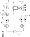
Fig. 8 is a schematic diagram of a compressed air system employed to move the driven rollers into engagement with the fabric members and to preheat the polymer strip. - As indicated above, the invention relates to an attachment for an existing sewing machine that enables a seam to be sewn and sealed in a single operation. As shown by
Fig. 1 , a typicalcommercial sewing machine 10 comprises anupright column 12, in which runs a drive belt from a motor (not shown) disposed under a table 14, the motor being controlled by afoot switch 20 or the like, atransverse arm 16, asewing mechanism 18, including aneedle 19 and a presser foot 21 (seeFig. 2 ), alever 13 for lifting thefoot 21 out of engagement withfabric members 7 and 9 to be sewn to one another, and aflywheel 22. These components are well known, and their functions are not affected by the present invention, although certain of these are used in additional ways according to the invention, as will be detailed below. - According to the invention, an
attachment 24 is attached to thesewing machine 10 by removing a cover plate (not shown) and assembling theattachment 24 in place of the cover plate. The details of this replacement of the cover plate by the attachment will of course vary somewhat from machine to machine; in each case, the attachment is designed so that the rollers (discussed further below) are disposed directly behindneedle 19. Also added is areel 23 dispensing astrip 25 of an adhesive thermoplastic polymer, and afeeder assembly 27 for directing thepolymer strip 25 into the seam being sewn. As compared to the adhesive tape used in prior seam sealing operations, which may be one inch wide by 0.002 - 0.003 inches thick, the strip employed according to the invention may typically be 1/8 - ¼ inch wide by 0.010- 0.020 inches thick, 0.014 inches being preferred. Thefeeder assembly 27 may be provided with a hot air duct and nozzle, to preheat thepolymer strip 25 and activate its adhesive properties prior to its being sewn into the seam.Fig. 8 shows details of the air system used to preheat thepolymer strip 25. - Further provided according to the invention is an
electronic control unit 26, which may comprise atouch screen 28 for receiving user input concerning the parameters necessary to control the process of sealing the seam, such as the temperature of heated rollers that apply heat and pressure to the seam to melt the polymer and seal the seam, and a microprocessor 29 (indicated as a component ofcomputer device 26 as "MP") for receiving these user inputs and other data, and for providing control signals to the various components of the attachment.Fig. 7 shows a block diagram of this circuitry. Also attached to thesewing machine 10 are a magnet 30 (seeFig. 6 ), mechanically affixed to theflywheel 22, and a Hall-effect sensor 32, likewise mechanically affixed to theupright column 12. - More specifically, as is well-known, in the process of sewing a seam, the
sewing machine 10 advances thefabric members 7 and 9 to be sewn together incrementally, by the desired length of the stitch, and thepresser foot 21 then holds them in place, so that theneedle 19 can puncture the fabric members while stationary. In so doingflywheel 22 is rotated intermittently. As will be discussed in detail below, the attachment of the invention comprises heatedrollers Fig. 4 ) that are driven to pull the fabric members through the attachment while applying heat and pressure to the seam so as to melt the polymer and seal the seam. In order to function properly, the driven rollers must cease pulling on the fabric members during the stitching process. In order that the operation of the rollers can be synchronized with that of the sewing machine, when themagnet 30 passes the Hall-effect sensor, the latter provides a signal ("HE" inFigs. 6 and7 ) that is provided to themicroprocessor 29 to control twomotors Figs. 1 and7 ) that drive the rollers. Signal HE is thus used to synchronize the operation of the rollers to the remainder of the sewing machine, so as to avoid distorting the fabric. The circuitry connecting themicroprocessor 29 to the various components providing and receiving the signals noted is not shown inFig. 1 , for clarity of the drawing, but will be readily understood and easily implemented by those of skill in the art. As above,Fig. 7 shows a schematic diagram of this circuitry. - As noted, operation of the sewing machine is controlled by a
foot pedal 20 or the like, such as a knee- or hand-operated switch operated by an operator. When the operator stops a given sewing operation, theheated rollers foot pedal 20 is provided tomicroprocessor 29 which in turn provides a control signal AC to anair cylinder 48. The assembly ofrollers motors air cylinder 48 and is withdrawn upwardly, out of engagement with the fabric members, when operation of thesewing machine 10 is stopped by the operator. At the same time the stream of hot air preheating the strip ofpolymer 25 is shut off. These operations are accordingly reversed when sewing is again initiated by the operator. - The signals provided by
microprocessor 29 also include three control signals H1, H2 and H3 provided torollers internal cartridge heaters 51. SeeFig. 5 . Idler rollers 50 (discussed further below) are likewise heated. - More specifically, in order that electrical connections can be made to the
cartridge heaters 51, they must be stationary, while drivenrollers idler rollers 50 must rotate freely overheaters 51. Theheaters 51 are designed to expand when current is applied, typically so as to fit snugly into a hole bored in a volume of material to be heated. In order that such expansion does not prevent rotation of the rollers, the cartridge heaters can be disposed insections 53 of steel tubing, while the rollers may be made of aluminum, bored to be a sliding fit over the steel tubes, and assembled with a small quantity of heat-conducting grease there- between. The greater coefficient of thermal expansion of aluminum as compared to that of steel will prevent the heating of thecartridge heaters 51 from interfering with rotation of the rollers. - As mentioned, the temperatures of the surfaces of the rollers can be measured directly using infrared sensors, if suitably durable components can be found. Alternatively, thermocouples can be provided to measure the temperatures of the
cartridge heaters 51, and this data used in a well-known proportional-integral-derivative (PID) feedback loop to control the temperatures of the surfaces of the rollers. Experimentation and appropriate testing will be required to determine the optimal parameters for the PID feedback loop, and these will likely vary with differing fabric types to be sewn and sealed to one another according to the invention. Such experimentation and testing to calibrate the feedback loop is within the skill of the art. - Turning now to the detailed mechanical details of the attachment of the invention,
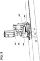
Fig. 4 shows an end view of the assembly of drivenheated rollers heated idler rollers 50, andbelt 52 in detail;Figs. 2 ,3 ,5 and6 show further features provided according to the invention.Rollers 50 are carried by achassis 56 that is assembled to thesewing machine 10, typically by attachment to the hinge (not shown) conventionally provided to allow the sewing machine to be pivoted out of its' "nest" in the sewing machine table 14.Fig. 4 is effectively taken frominside chassis 56, so as to show the ends ofrollers 50.Chassis 56 has an inclined leadingsurface 56a (seeFig. 2 ) that assists in feeding the sewn fabric members from beneathpresser foot 21 to between the drivenrollers idler rollers 50.Fig. 4 also shows thethread 17, which will typically be the polymer-coated thread described in the Ferreiro applications.Chassis 56 is preferably spaced from thesewing machine 10 by insulating spacers (not shown) to allow air to pass there between and avoid overheating thesewing machine 10. - A
continuous belt 52 fits overrollers 50 and moves together with thefabric members 7 and 9 to be sewn, which are indicated by a heavybroken line 58 inFig. 4 .Belt 52 rides over a final,unheated roller 60, and is tensioned bysprings 54 on either side of thechassis 56, biasing roller 60 (leftwardly in the view ofFig. 4 ) toward the "downstream" end ofchassis 56; the degree of tension inbelt 52 may be adjusted by provision ofdiffering springs 54, or by adjustment of the preload provided. As indicated byFig. 3 , the biasingroller 60 is mounted in aslot 56b inchassis 56, to allow it to move to adjust the tension inbelt 52. - As illustrated, the
fabric members 7 and 9 to be bonded to one another are urged bybelt 52 into engagement withrollers rollers idler rollers 50, ensuring good heat transfer betweenrollers belt 52 were omitted, heat transfer would end to take place only along lines at which theidler rollers 50 are juxtaposed to the drivenrollers Belt 52 can be made of a composite of fiberglass cloth coated by one or more layers of Teflon® material. Given that these materials, as well as those of most fabrics, are relatively insulative, the extension of the heat transfer area provided by provision of thebelt 52 is highly beneficial in ensuring sufficient heat transfer to effectively melt the polymer materials of thethread 17 andstrip 25, and thereby effectively sealing the seam.Belt 52 also prevents the fabric members from being tangled inrollers 50. - In the preferred embodiment, the axes of driven
rollers idler rollers 50, as illustrated byFig. 4 . When the driven rollers are withdrawn upwardly, at the end of a sewing operation, the spring tension provided tounheated idler roller 60 bysprings 54 will causeroller 60 to move leftwardly, so thatbelt 52 will take a straight-line path over the upper surfaces ofidler rollers 50. When the drivenrollers belt 52 will be forced away from the straight-line path so as to conform to the lower circumferential surfaces ofrollers idler rollers 50, taking the form shown inFig. 4 , while thesprings 54 allow theunheated idler roller 60 to move rightwardly in the view ofFig. 4 . - More specifically, as the fabric members with the polymer strip therebetween are drawn through the heated rollers, the heat and pressure provided by the rollers melts the
preheated polymer strip 25 and squeezes it laterally, filling the space between thefabric members 7 and 9. Normally the practice of the invention will also involve the use of the polymer-laden thread 17 of the Ferriero applications, so that the polymer of thethread 17 is melted at the same time, filling the punctures left by the needle. However, it may be possible to avoid use of thethread 17 in favor of a plain thread, and simply filling the needle punctures with the polymer from thestrip 25, and such is accordingly also within the scope of the invention. Likewise, in some applications thepolymer strip 25 may be avoided and only thethread 17 used. - The polymers applied to the
thread 17 and that ofstrip 25 may be the same or may differ. As of the filing of this application, experimentation is being performed to identify the optimal materials for these purposes. They may be as disclosed in the Ferreiro application, that is, thermoplastic polyurethane, or possibly materials selected from the group including nylon, polyester, polyolefin and vinyl, and mixtures and combinations thereof. It will be appreciated that these materials have good adhesive properties, so that the seam is strengthened as well as sealed by practice of the invention. The materials used in the prior art seam sealing processes may also be used. Preferably, the polymer is applied to the thread in a bath of molten polymer, so that the polymer is absorbed into the yarns of the thread, followed by passage through a die or the like, squeezing out extra polymer, so the final polymer content of the thread is 2 - 6 % by weight, as in the Ferreiro applications. - As shown in
Fig. 6 , the "upstream"rollers motor 36 by way of afirst belt 60, while the "downstream"roller 40 is driven separately bymotor 34 by way of asecond belt 62. Themotors Figs. 1 and7 ) respectively, so that the rollers can be driven at different speeds as desired. Preferably, thedownstream roller 40 is driven at a slightly higher speed than theupstream rollers - Other preferred aspects of the design include the following:
The surfaces of drivenrollers fabric members 7 and 9. A coating is applied to produce a non-stick surface. - An operator-controlled cutter (not shown) may be provided between the
rollers presser foot 21, to cut thepolymer strip 25 at the end of the seam. -
Rollers Fig. 2 ) that is pivoted transversely at 66 with respect to the movingactuator 68 ofair cylinder 48. This pivoting allows the rollers to remain in contact with thefabric members 7 and 9 despite some degree of irregularity in the thickness of the fabric members, such as where several fabric members cross one another.Therollers - As mentioned above,
Fig. 7 is a schematic diagram of the electrical circuitry provided according to the invention. Where feasible, the components and control signals identified earlier are identified here as well. Thus, an electronic control unit (ECU) 80, which may comprisemicroprocessor 29 and associated supporting components, including a user interface such astouch screen 26, receives sensor inputs and provides control signals through appropriate interface circuit boards. Thus, for example, a set oftemperature sensors 70 for the lower roller assembly, that is,idler rollers 50, a set oftemperature sensors 72 for the drivenrollers process temperature sensor 73 for measuring the temperature of the stream of air preheating thepolymer tape 25, each provide temperature data to asensor input board 74.Sensor input board 74 then performs simple operations on the data, for example, analog-to-digital conversion, and provides the results toECU 80 as indicated at 76. As discussed above, the signals responsive to roller temperature may represent direct measurement of the temperature of the rollers or may represent measurement of the temperature of thecartridge heaters 51. - In either case, the temperature measurement signals are used by
ECU 80 to generate temperature control signals by way of a well-known proportional-integral-derivative (PID) feedback loop. These control signals are then provided to arelay control board 82, which uses the control signals fromECU 80 to drive relays onboard 82 to control supply of current to the various heating elements, including the lowerassembly heating elements 84, that is, the cartridge heaters inidler rollers 50, the upper assembly heating elements 86, that is, the cartridge heaters in drivenrollers process heating element 88, heating the stream of air employed to preheat thepolymer tape 25. - Similarly, the signal HE from the Hall-
effect sensor 32 is provided to theECU 80 and used to synchronize the operation ofdrive motors motor control board 84, which directly controls operation ofmotors - Likewise,
foot switch 20 provides signal SW toECU 80, thereby indicating that sewing is to start or to stop. In response to a stop signal,ECU 80 provides signal AC to relaycontrol board 82, which then operates the air cylinder via solenoid valve(s) 92 to lift the heated drivenrollers hot air solenoid 90 to cut off the supply of hot air preheatingpolymer tape 25. While thefabric members 7 and 9 may remain in contact withbelt 52 whilerollers fabric members 7 and 9, the fact that no pressure is then being exerted prevents the fabric from being scorched by heat from theidler rollers 50. -
Fig. 8 shows as mentioned a schematic diagram of the pneumatic components employed. Compressed air is supplied at 94 and is supplied to afirst solenoid valve 90 which controls flow of air for preheating thepolymer strip 25. The pressure in the supply line is controlled by aregulator 96, and the air is heated by aheater 88. The heater is controlled bycontrol unit 80 in response to a signal fromsensor 73, as discussed above. The hot air impinges on thepolymer strip 25 as it exitsfeeder 27, as illustrated. - A second stream of air is provided to solenoid
valves 92, connected toair cylinder 48 as shown, in order to controllably raise andlower roller assembly 24 as desired. - Thus, in operation of the sewing machine with the attachment according to the invention, the
sewing machine 10 is first preferably supplied with the polymer-bearing thread 17 (Fig. 4 ) according to the Ferreiro application referred to above. Thepolymer strip 25 is placed between thefabric members 7 and 9, and this assemblage is hand-fed under thepresser foot 21. The foot switch 20 (or equivalent, such as a knee-operated lever switch) is then actuated by the operator, causing the sewing machine to operate as usual. At the same time, according to the invention,rollers polymer strip 25, and are driven in synchronism with the operation of thesewing machine 10 to pull the assemblage betweenrollers idler rollers 50, withbelt 52 therebetween, so that the assemblage is heated to melt the polymer oftape 25 and that of thethread 17. - More specifically, the
preheated polymer strip 25 is drawn into the machine between the twofabric members 7 and 9, the fabric members are stitched together, and a final application of heat to raise the polymer above its solid-to-liquid transition temperature is provided from the rollers. At the same time, the rollers also provide pressure, which flattens the seam, and squeezes the polymer in the seam between the needle punctures. The application of pressure also provides better heat transfer through the fabric to the polymer, as well as deforming the lower belt to give greater surface area for improved heat transfer efficiency. After exiting the roller assembly, the polymer rapidly cools and is set. At present, no separate cooling step appears necessary, but such is within the invention if needed. - It will be appreciated that while a single needle sewing a simple seam has been illustrated, other sewing operations, such as double-needle sewing or sewing of more complex seams, such as interlocking "felled" seams, may be readily accommodated. It will also be appreciated that the sewing machine could be used as usual, that is, without employment of the attachment of the invention, while it remains in place; that minimal modification of the sewing machine is needed to employ the attachment of the invention to simultaneously sew and seal seams; and that minimal operator training is needed.
- While a preferred embodiment of the invention has been described in detail, the invention is not to be limited thereto, but only by the following claims.
Claims (17)
- An attachment (24) for being attached to a sewing machine (10) to allow simultaneous sewing and sealing of a seam between fabric members, comprising:a reel (23) for supply of a strip (25) of thermoplastic polymer material;a feeder assembly (27) for feeding the polymer strip (25) between the fabric members;characterized in that said attachment further comprises:a control unit (26) for receiving operational signals from said sewing machine, said signals including a synchronization signal and a signal from an operator-controlled switch for initiating sewing operations;a plurality of driven rollers (40, 42, 44);a pair of idler rollers (50) opposed to each of said driven rollers;a continuous belt (52) disposed over said idler rollers;each of said driven rollers (40, 42, 44) and idler rollers (50) being controllably heated responsive to control signals from said control unit;said driven rollers (40, 42, 44) being driven intermittently by motors controlled by said control unit responsive to said synchronization signal; andsaid driven rollers (40, 42, 44) being brought into engagement with said fabric members in response to said signal from an operator-controlled switch for initiating sewing operations.
- The attachment of claim 1, wherein said driven and idler rollers are heated by cartridge heaters (51) disposed in bores in said rollers,
wherein optionally the temperature of the surfaces of said driven (40, 42, 44) and idler (50) rollers is controlled by said control unit (26) responsive to measurement of the temperature of said cartridge heaters (51), using a calibrated feedback loop. - The attachment of claim 1, further comprising a heater (88) for heating a stream of air, and a nozzle disposed with respect to said feeder assembly (27) so as employ said stream of heated air to preheat the polymer strip prior to its being fed between the fabric members.
- The attachment of claim 1, wherein said driven rollers (40, 42, 44) are mounted on a frame (64), and wherein said frame (64) is supported by an air cylinder (48) controlled by said control unit (26) to bring said driven rollers (40, 42, 44) into engagement with said fabric members, responsive to said signal from an operator-controlled switch (20) for initiating sewing operations.
- The attachment of claim 4, wherein said frame (64) is pivotably mounted with respect to said air cylinder (48).
- The attachment of claim 1, wherein said synchronization signal is provided by attachment of a magnet (30) to a flywheel (22) of said sewing machine, and by attachment of a Hall-effect sensor (32) to said sewing machine so as to be juxtaposed to said magnet (30) when said flywheel (22) rotates in operation of said sewing machine, whereby said Hall-effect sensor (32) provides said synchronization signal to said control unit (26).
- The attachment of claim 1, wherein said plurality of idler rollers (50) are carried by a chassis (56) attached to said sewing machine.
- The attachment of claim 7, wherein said chassis (56) carries a further unheated roller(60) over which said belt passes, the axis of said further unheated roller being movable to control the tension in said belt (52).
- The attachment of claim 8, wherein said unheated roller (60) is spring-biased to control the tension in said belt (52).
- The attachment of claim 9, wherein when said driven rollers (40, 42, 44) are engaged with said fabric members, said belt (52) is deformed so as to urge said fabric members against a portion of the circumference of each of said driven rollers (40, 42, 44).
- A method for forming a waterproof seam between at least two fabric members, comprising the steps of:providing a quantity of thread (17) comprising between about 2% and about 6% by weight of a thermoplastic polymer selected from the group consisting of polyurethane, nylon, polyester, polyolefin, and vinyl;employing a sewing machine (10) to cause a needle (19) to puncture said at least two fabric members at regular intervals and to draw said thread through said punctures, to form a sewn seam;inserting a strip (25) of thermoplastic polymer selected from the group consisting of polyurethane, nylon, polyester, polyolefin, and vinyl between said at least two fabric members while forming said sewn seam;providing a plurality of heated, driven rollers (40, 42, 44);providing a pair of idler rollers (50) opposed to each of said driven rollers (40, 42, 44); providing a continuous belt (52) disposed over said idler rollers (50); passing said at least two fabric members with said strip of polymer therebetween between said heated driven rollers (40, 42, 44) and said pairs of idler rollers (50), wherein said rollers (40, 42, 44, 50) are disposed directly behind the needle (19);urging said heated driven rollers (40, 42, 44) towards said pairs of idler rollers (50), so as to apply heat and pressure to said seam so as to melt said polymer from said thread (17), whereby said polymer from said thread fills said punctures, and so as to melt said polymer from said strip (25),allowing said polymer comprised by said thread (17) to cool and solidify, whereby said punctures are sealed against ingress of water; andallowing said polymer of the strip (25) to cool and solidify, whereby said seam between each puncture hole is sealed against ingress of water.
- The method of claim 11, wherein the thermoplastic polymer materials comprised by said thread (17) and comprised by said strip (25) are the same.
- The method of claim 11, wherein said pairs of idler rollers (50) are carried by a chassis (56) fixed to said sewing machine.
- The method of claim 13, wherein said chassis (56) carries a further unheated roller (60) over which said belt (52) passes, the axis of said further unheated roller(60) being movable to control the tension in said belt (52).
- The method of claim 14, wherein said unheated roller (60) is spring-biased to control the tension in said belt (52).
- The method of claim 15, wherein when said driven rollers (40, 42, 44) are engaged with said fabric members, said belt (52) is deformed so as to urge said fabric members against a portion of the circumference of each of said driven rollers (40, 42, 44).
- The method of claim 11, wherein said plurality of driven rollers (40, 42, 44) comprises at least three rollers, arranged such that their axes are substantially coplanar, as are those of the idler rollers (50), and wherein the downstream roller (40) is driven at higher speed than the upstream rollers (42, 44), such that tension is exerted on the assembly of fabric members as the polymer is melted and the seam compressed.
Applications Claiming Priority (2)
| Application Number | Priority Date | Filing Date | Title |
|---|---|---|---|
| US15/932,105 US10934647B2 (en) | 2018-02-05 | 2018-02-05 | Attachment for sealing seams |
| PCT/US2019/016390 WO2019152867A1 (en) | 2018-02-05 | 2019-02-01 | Attachment for sealing seams |
Publications (4)
| Publication Number | Publication Date |
|---|---|
| EP3749508A1 EP3749508A1 (en) | 2020-12-16 |
| EP3749508A4 EP3749508A4 (en) | 2021-10-20 |
| EP3749508B1 true EP3749508B1 (en) | 2023-08-16 |
| EP3749508C0 EP3749508C0 (en) | 2023-08-16 |
Family
ID=67475967
Family Applications (1)
| Application Number | Title | Priority Date | Filing Date |
|---|---|---|---|
| EP19748424.9A Active EP3749508B1 (en) | 2018-02-05 | 2019-02-01 | Attachment for sealing seams |
Country Status (6)
| Country | Link |
|---|---|
| US (3) | US10934647B2 (en) |
| EP (1) | EP3749508B1 (en) |
| JP (1) | JP2021512766A (en) |
| CN (1) | CN111819068B (en) |
| ES (1) | ES2962759T3 (en) |
| WO (1) | WO2019152867A1 (en) |
Families Citing this family (8)
| Publication number | Priority date | Publication date | Assignee | Title |
|---|---|---|---|---|
| CN110973752A (en) * | 2019-12-06 | 2020-04-10 | 山东舒朗服装服饰股份有限公司 | Apparatus and method for sticking and ironing tapes embedded in clothing fabrics |
| CN113774570B (en) * | 2021-09-23 | 2023-05-16 | 常德远程医疗科技有限公司 | Production equipment for integrated medical personnel protective clothing |
| US11690422B1 (en) * | 2022-04-01 | 2023-07-04 | CreateMe Technologies LLC | Garment assembly system |
| CN115581325B (en) * | 2022-09-08 | 2023-05-09 | 河南省安邦卫材有限公司 | Heat sealing device for producing medical protective clothing |
| TWI854700B (en) * | 2023-06-13 | 2024-09-01 | 高林股份有限公司 | Rotary shuttle electric-controlled heat dissipation apparatus |
| CN117604727B (en) * | 2023-12-07 | 2025-09-23 | 台州市产品质量安全检测研究院 | Automatic sewing machine with shaping mechanism |
| CN117783127B (en) * | 2023-12-26 | 2024-07-02 | 广州宇龙汽车零部件有限公司 | Automatic visual detection workstation of general leak protection welding |
| CN118216736A (en) * | 2024-03-20 | 2024-06-21 | 安踏(中国)有限公司 | A hot-melt thread sewing process and clothing |
Family Cites Families (42)
| Publication number | Priority date | Publication date | Assignee | Title |
|---|---|---|---|---|
| US1560712A (en) | 1921-07-21 | 1925-11-10 | Gem Shirt Company | Seam for garments |
| US2115368A (en) | 1935-08-03 | 1938-04-26 | Lustberg Benjamin Herbert | Seam |
| US2465374A (en) | 1944-03-20 | 1949-03-29 | Warren Featherbone Co | Waterproof fabric seam |
| US2702067A (en) | 1952-09-19 | 1955-02-15 | Metacomet Mfg Company Inc | Machine for making covered apparel belts |
| GB873347A (en) * | 1956-10-24 | 1961-07-26 | Baxter Brothers And Company Lt | Improvements in or relating to plastic coated or impregnated fabrics |
| US3272682A (en) | 1962-08-13 | 1966-09-13 | Cavitron Ultrasonics Inc | Apparatus for joining thermoplastic sheet material with ultrasonic rotary vibrators |
| US3457739A (en) | 1966-03-14 | 1969-07-29 | Minnesota Mining & Mfg | Bonding of fabric with adhesive thread |
| DE2363078C2 (en) * | 1973-12-19 | 1984-08-30 | Heinrich Kuper GmbH & Co KG, 4835 Rietberg | Device for fastening two layers of material |
| US4016822A (en) * | 1975-11-20 | 1977-04-12 | Shap, Inc. | Seam folding and pressing attachment for sewing machines |
| HU180143B (en) * | 1980-05-29 | 1983-02-28 | Csepel Muevek Jarmue | Band furthering automatic sewing machine for making short seam |
| IT1140105B (en) * | 1980-12-19 | 1986-09-24 | Duerkoppwerke | MACHINE TO CYCLE WITH A UPPER AND A LOWER PUSHING PUSH |
| DE3481287D1 (en) | 1983-05-20 | 1990-03-15 | Pfaff Ind Masch | METHOD FOR CONNECTING FABRIC LAYERS COATED ON ONE SIDE WITH THERMOPLASTIC PLASTIC, CONNECTING AFTER THE METHOD AND DEVICE FOR CARRYING OUT THE METHOD. |
| FI73011C (en) | 1983-09-12 | 1987-08-10 | Lasse Liukko | FOERFARANDE FOER TILLVERKNING AV EN SOEM. |
| DE3921010C1 (en) | 1989-06-27 | 1990-06-21 | W.L. Gore & Associates Gmbh, 8011 Putzbrunn, De | |
| US5003902A (en) | 1989-10-13 | 1991-04-02 | Superior Surgical Manufacturing Co. Inc. | Seam having liquid proof threads stichably securing first and second liquid proof materials foldably enclosing a meltable adhesive polymer film and method of manufacture of same |
| US5162149A (en) | 1990-05-15 | 1992-11-10 | W. L. Gore & Associates, Inc. | Non-blocking seam tape |
| DE4215177A1 (en) | 1992-05-08 | 1993-11-11 | Ebert Gerd | Sewing thread with improved adhesion and water tightness - has coating for precursor material which increases in vol. on activation |
| JPH0671079A (en) * | 1992-08-27 | 1994-03-15 | Brother Ind Ltd | Needle stop position controller of sewing machine |
| JP3266736B2 (en) | 1994-05-17 | 2002-03-18 | 三菱電機株式会社 | Magnetic sensor |
| JP3450429B2 (en) * | 1994-05-30 | 2003-09-22 | クインライト電子精工株式会社 | Hot air type heat welding equipment |
| JP3547138B2 (en) | 1994-11-18 | 2004-07-28 | 旭化成せんい株式会社 | Improved joint structure of waterproof fabric |
| US5670577A (en) | 1995-09-29 | 1997-09-23 | H. B. Fuller Licensing & Financing, Inc. | Waterproof hot melt composition for stitched seams |
| US6293080B1 (en) | 1996-06-28 | 2001-09-25 | Teijin Limited | Sewing thread for leather products and leather products produced by using the same |
| US6576078B2 (en) * | 2001-04-11 | 2003-06-10 | Xerox Corporation | Flashless hot melt bonding of adhesives for imageable seamed belts |
| US20030010439A1 (en) * | 2001-07-16 | 2003-01-16 | Fenton Jay Thomas | Seam sealing apparatus and process therefor |
| CN1158950C (en) * | 2001-10-18 | 2004-07-28 | 广东溢达纺织有限公司 | Wrinkle resisting finish process of shirt wormiam bone |
| FR2840327B1 (en) * | 2002-05-29 | 2004-11-05 | Christian Guilhem | METHOD AND MACHINE FOR MAKING A SEWING NOT LIKELY TO RECOVER |
| SI1507910T1 (en) | 2002-05-29 | 2006-10-31 | C Gex Systems C Gex S A R L | Method and machine for production of a non-unravelling seam |
| TW587047B (en) | 2002-08-16 | 2004-05-11 | Primax Electronics Ltd | Hot laminating apparatus having single-side transmitting and hot laminating roller |
| US6789592B2 (en) * | 2002-10-18 | 2004-09-14 | Gore Enterprise Holdings, Inc. | Apparatus and method for guiding the seam allowance in seam sealing |
| JP2004208824A (en) * | 2002-12-27 | 2004-07-29 | Nisshinbo Ind Inc | Waterproof sewing product and manufacturing method thereof |
| US7455743B2 (en) | 2003-05-21 | 2008-11-25 | Mountain Hardwear, Inc. | Adhesively bonded seams and methods of forming seams |
| FR2873545B1 (en) * | 2004-07-29 | 2007-09-28 | Salomon Sa | SPORTSWEAR |
| JP4664096B2 (en) * | 2005-03-04 | 2011-04-06 | 藤倉航装株式会社 | Waterproof seam sealing machine |
| US20120317837A1 (en) * | 2011-06-17 | 2012-12-20 | Columbia Sportswear North America, Inc. | Self sealing vulcanized system for waterproof coupling of uppers to outsoles |
| US20130048219A1 (en) * | 2011-08-24 | 2013-02-28 | Roxanne Ferreiro | Adhesive Thread System |
| US9290870B2 (en) | 2013-02-04 | 2016-03-22 | Geoff McCue | Stitching apparatus and method of use |
| US10750799B2 (en) * | 2013-03-14 | 2020-08-25 | Medline Industries, Inc. | Surgeon gown with sealed sleeves and methods of manufacturing the same |
| CN105593077A (en) | 2013-09-30 | 2016-05-18 | 关键安全体系股份有限公司 | Airbag with sealed seam |
| JP6637699B2 (en) * | 2015-09-02 | 2020-01-29 | ユニ・チャーム株式会社 | Method for producing composite sheet according to absorbent article, apparatus for producing composite sheet according to absorbent article, and composite sheet according to absorbent article |
| JP2017074269A (en) * | 2015-10-16 | 2017-04-20 | Juki株式会社 | sewing machine |
| JP6757914B2 (en) | 2016-04-01 | 2020-09-23 | ヤマトミシン製造株式会社 | High frequency sewing machine |
-
2018
- 2018-02-05 US US15/932,105 patent/US10934647B2/en active Active
-
2019
- 2019-02-01 JP JP2020564029A patent/JP2021512766A/en not_active Ceased
- 2019-02-01 CN CN201980011886.0A patent/CN111819068B/en active Active
- 2019-02-01 ES ES19748424T patent/ES2962759T3/en active Active
- 2019-02-01 EP EP19748424.9A patent/EP3749508B1/en active Active
- 2019-02-01 WO PCT/US2019/016390 patent/WO2019152867A1/en not_active Ceased
-
2021
- 2021-01-08 US US16/974,389 patent/US11591731B2/en active Active
-
2022
- 2022-12-20 US US18/068,618 patent/US11746453B2/en active Active
Also Published As
| Publication number | Publication date |
|---|---|
| CN111819068A (en) | 2020-10-23 |
| JP2021512766A (en) | 2021-05-20 |
| US10934647B2 (en) | 2021-03-02 |
| ES2962759T3 (en) | 2024-03-21 |
| WO2019152867A1 (en) | 2019-08-08 |
| EP3749508A4 (en) | 2021-10-20 |
| US20210130995A1 (en) | 2021-05-06 |
| CN111819068B (en) | 2022-09-30 |
| US20190242044A1 (en) | 2019-08-08 |
| US11591731B2 (en) | 2023-02-28 |
| EP3749508A1 (en) | 2020-12-16 |
| EP3749508C0 (en) | 2023-08-16 |
| US20230141286A1 (en) | 2023-05-11 |
| US11746453B2 (en) | 2023-09-05 |
Similar Documents
| Publication | Publication Date | Title |
|---|---|---|
| US11746453B2 (en) | Attachment for sealing seams | |
| US6471803B1 (en) | Rotary hot air welder and stitchless seaming | |
| US6517651B2 (en) | Apparatus and method for joining fabrics without sewing | |
| KR920007788A (en) | Adjustable window cover | |
| TWI731055B (en) | High frequency sewing machine | |
| CN107618187B (en) | Method for joining at least partially overlapping material layers and automatic joining device for carrying out the method | |
| EP2216162B1 (en) | Cloth bonding apparatus | |
| US20130048219A1 (en) | Adhesive Thread System | |
| ITMI20101270A1 (en) | MACHINE TO JOIN OR TAPE A FABRIC | |
| US2422676A (en) | Means for producing a waterproof seam for polyvinyl resinous coated fabrics | |
| EP4378667A1 (en) | Apparatus and method for taping fabrics or similar articles | |
| Jones | The use of heat sealing, hot air and hot wedge to join textile materials | |
| KR102087190B1 (en) | The manufacuring equipment for a fusible interlining | |
| JP6155096B2 (en) | Bonding device | |
| JP4145522B2 (en) | Method for controlling temperature of plastic film to be bonded, and apparatus for bonding plastic film using temperature-controlled transport roll | |
| KR101815221B1 (en) | Device for seamless join and seamline coating | |
| CN117604727B (en) | Automatic sewing machine with shaping mechanism | |
| US7640879B2 (en) | Presser foot | |
| JP2014058148A (en) | High frequency sewing machine | |
| US4259131A (en) | Method and apparatus for fusing strips | |
| JPS5852113Y2 (en) | Cutting and welding equipment in bag making machines | |
| CN113442479A (en) | Manufacturing process of large-circumference seamless annular conveying belt | |
| Samarasinghe | Design and manufacture of glue elastic making machine | |
| HK1110101B (en) | A fabric-processing device and a method of fusing an article of clothing | |
| HK1118676B (en) | Hemming system and method for hemming a fabric without using seams, by introducing an adhesively processed resilient element into one or two opposite surfaces of the fabric |
Legal Events
| Date | Code | Title | Description |
|---|---|---|---|
| STAA | Information on the status of an ep patent application or granted ep patent |
Free format text: STATUS: THE INTERNATIONAL PUBLICATION HAS BEEN MADE |
|
| PUAI | Public reference made under article 153(3) epc to a published international application that has entered the european phase |
Free format text: ORIGINAL CODE: 0009012 |
|
| STAA | Information on the status of an ep patent application or granted ep patent |
Free format text: STATUS: REQUEST FOR EXAMINATION WAS MADE |
|
| 17P | Request for examination filed |
Effective date: 20200901 |
|
| AK | Designated contracting states |
Kind code of ref document: A1 Designated state(s): AL AT BE BG CH CY CZ DE DK EE ES FI FR GB GR HR HU IE IS IT LI LT LU LV MC MK MT NL NO PL PT RO RS SE SI SK SM TR |
|
| AX | Request for extension of the european patent |
Extension state: BA ME |
|
| DAV | Request for validation of the european patent (deleted) | ||
| DAX | Request for extension of the european patent (deleted) | ||
| A4 | Supplementary search report drawn up and despatched |
Effective date: 20210921 |
|
| RIC1 | Information provided on ipc code assigned before grant |
Ipc: A41H 43/04 20060101ALI20210915BHEP Ipc: D05B 17/00 20060101ALI20210915BHEP Ipc: D05B 1/26 20060101ALI20210915BHEP Ipc: B29C 65/72 20060101AFI20210915BHEP |
|
| GRAP | Despatch of communication of intention to grant a patent |
Free format text: ORIGINAL CODE: EPIDOSNIGR1 |
|
| STAA | Information on the status of an ep patent application or granted ep patent |
Free format text: STATUS: GRANT OF PATENT IS INTENDED |
|
| INTG | Intention to grant announced |
Effective date: 20230301 |
|
| GRAS | Grant fee paid |
Free format text: ORIGINAL CODE: EPIDOSNIGR3 |
|
| GRAA | (expected) grant |
Free format text: ORIGINAL CODE: 0009210 |
|
| STAA | Information on the status of an ep patent application or granted ep patent |
Free format text: STATUS: THE PATENT HAS BEEN GRANTED |
|
| AK | Designated contracting states |
Kind code of ref document: B1 Designated state(s): AL AT BE BG CH CY CZ DE DK EE ES FI FR GB GR HR HU IE IS IT LI LT LU LV MC MK MT NL NO PL PT RO RS SE SI SK SM TR |
|
| REG | Reference to a national code |
Ref country code: CH Ref legal event code: EP Ref country code: DE Ref legal event code: R096 Ref document number: 602019035152 Country of ref document: DE |
|
| REG | Reference to a national code |
Ref country code: IE Ref legal event code: FG4D |
|
| U01 | Request for unitary effect filed |
Effective date: 20230912 |
|
| U07 | Unitary effect registered |
Designated state(s): AT BE BG DE DK EE FI FR IT LT LU LV MT NL PT SE SI Effective date: 20230920 |
|
| REG | Reference to a national code |
Ref country code: NO Ref legal event code: T2 Effective date: 20230816 |
|
| PG25 | Lapsed in a contracting state [announced via postgrant information from national office to epo] |
Ref country code: GR Free format text: LAPSE BECAUSE OF FAILURE TO SUBMIT A TRANSLATION OF THE DESCRIPTION OR TO PAY THE FEE WITHIN THE PRESCRIBED TIME-LIMIT Effective date: 20231117 |
|
| PG25 | Lapsed in a contracting state [announced via postgrant information from national office to epo] |
Ref country code: IS Free format text: LAPSE BECAUSE OF FAILURE TO SUBMIT A TRANSLATION OF THE DESCRIPTION OR TO PAY THE FEE WITHIN THE PRESCRIBED TIME-LIMIT Effective date: 20231216 |
|
| PG25 | Lapsed in a contracting state [announced via postgrant information from national office to epo] |
Ref country code: RS Free format text: LAPSE BECAUSE OF FAILURE TO SUBMIT A TRANSLATION OF THE DESCRIPTION OR TO PAY THE FEE WITHIN THE PRESCRIBED TIME-LIMIT Effective date: 20230816 Ref country code: IS Free format text: LAPSE BECAUSE OF FAILURE TO SUBMIT A TRANSLATION OF THE DESCRIPTION OR TO PAY THE FEE WITHIN THE PRESCRIBED TIME-LIMIT Effective date: 20231216 Ref country code: HR Free format text: LAPSE BECAUSE OF FAILURE TO SUBMIT A TRANSLATION OF THE DESCRIPTION OR TO PAY THE FEE WITHIN THE PRESCRIBED TIME-LIMIT Effective date: 20230816 Ref country code: GR Free format text: LAPSE BECAUSE OF FAILURE TO SUBMIT A TRANSLATION OF THE DESCRIPTION OR TO PAY THE FEE WITHIN THE PRESCRIBED TIME-LIMIT Effective date: 20231117 |
|
| PG25 | Lapsed in a contracting state [announced via postgrant information from national office to epo] |
Ref country code: PL Free format text: LAPSE BECAUSE OF FAILURE TO SUBMIT A TRANSLATION OF THE DESCRIPTION OR TO PAY THE FEE WITHIN THE PRESCRIBED TIME-LIMIT Effective date: 20230816 |
|
| REG | Reference to a national code |
Ref country code: ES Ref legal event code: FG2A Ref document number: 2962759 Country of ref document: ES Kind code of ref document: T3 Effective date: 20240321 |
|
| PG25 | Lapsed in a contracting state [announced via postgrant information from national office to epo] |
Ref country code: SM Free format text: LAPSE BECAUSE OF FAILURE TO SUBMIT A TRANSLATION OF THE DESCRIPTION OR TO PAY THE FEE WITHIN THE PRESCRIBED TIME-LIMIT Effective date: 20230816 Ref country code: RO Free format text: LAPSE BECAUSE OF FAILURE TO SUBMIT A TRANSLATION OF THE DESCRIPTION OR TO PAY THE FEE WITHIN THE PRESCRIBED TIME-LIMIT Effective date: 20230816 Ref country code: SK Free format text: LAPSE BECAUSE OF FAILURE TO SUBMIT A TRANSLATION OF THE DESCRIPTION OR TO PAY THE FEE WITHIN THE PRESCRIBED TIME-LIMIT Effective date: 20230816 |
|
| REG | Reference to a national code |
Ref country code: DE Ref legal event code: R097 Ref document number: 602019035152 Country of ref document: DE |
|
| PLBE | No opposition filed within time limit |
Free format text: ORIGINAL CODE: 0009261 |
|
| STAA | Information on the status of an ep patent application or granted ep patent |
Free format text: STATUS: NO OPPOSITION FILED WITHIN TIME LIMIT |
|
| 26N | No opposition filed |
Effective date: 20240517 |
|
| PG25 | Lapsed in a contracting state [announced via postgrant information from national office to epo] |
Ref country code: MC Free format text: LAPSE BECAUSE OF FAILURE TO SUBMIT A TRANSLATION OF THE DESCRIPTION OR TO PAY THE FEE WITHIN THE PRESCRIBED TIME-LIMIT Effective date: 20230816 |
|
| REG | Reference to a national code |
Ref country code: CH Ref legal event code: PL |
|
| PG25 | Lapsed in a contracting state [announced via postgrant information from national office to epo] |
Ref country code: CH Free format text: LAPSE BECAUSE OF NON-PAYMENT OF DUE FEES Effective date: 20240229 |
|
| GBPC | Gb: european patent ceased through non-payment of renewal fee |
Effective date: 20240201 |
|
| PG25 | Lapsed in a contracting state [announced via postgrant information from national office to epo] |
Ref country code: CZ Free format text: LAPSE BECAUSE OF NON-PAYMENT OF DUE FEES Effective date: 20240201 |
|
| U90 | Renewal fees not paid: noting of loss of rights |
Free format text: RENEWAL FEE NOT PAID FOR YEAR 06 Effective date: 20240926 |
|
| PG25 | Lapsed in a contracting state [announced via postgrant information from national office to epo] |
Ref country code: NO Free format text: LAPSE BECAUSE OF NON-PAYMENT OF DUE FEES Effective date: 20240229 Ref country code: CZ Free format text: LAPSE BECAUSE OF NON-PAYMENT OF DUE FEES Effective date: 20240201 Ref country code: CH Free format text: LAPSE BECAUSE OF NON-PAYMENT OF DUE FEES Effective date: 20240229 |
|
| U93 | Unitary patent lapsed |
Free format text: RENEWAL FEE NOT PAID Effective date: 20240229 |
|
| PG25 | Lapsed in a contracting state [announced via postgrant information from national office to epo] |
Ref country code: GB Free format text: LAPSE BECAUSE OF NON-PAYMENT OF DUE FEES Effective date: 20240201 |
|
| PG25 | Lapsed in a contracting state [announced via postgrant information from national office to epo] |
Ref country code: IE Free format text: LAPSE BECAUSE OF NON-PAYMENT OF DUE FEES Effective date: 20240201 |
|
| PG25 | Lapsed in a contracting state [announced via postgrant information from national office to epo] |
Ref country code: IE Free format text: LAPSE BECAUSE OF NON-PAYMENT OF DUE FEES Effective date: 20240201 Ref country code: GB Free format text: LAPSE BECAUSE OF NON-PAYMENT OF DUE FEES Effective date: 20240201 |
|
| REG | Reference to a national code |
Ref country code: ES Ref legal event code: FD2A Effective date: 20250326 |
|
| PG25 | Lapsed in a contracting state [announced via postgrant information from national office to epo] |
Ref country code: ES Free format text: LAPSE BECAUSE OF NON-PAYMENT OF DUE FEES Effective date: 20240202 |
|
| PG25 | Lapsed in a contracting state [announced via postgrant information from national office to epo] |
Ref country code: CY Free format text: LAPSE BECAUSE OF FAILURE TO SUBMIT A TRANSLATION OF THE DESCRIPTION OR TO PAY THE FEE WITHIN THE PRESCRIBED TIME-LIMIT; INVALID AB INITIO Effective date: 20190201 |
|
| PG25 | Lapsed in a contracting state [announced via postgrant information from national office to epo] |
Ref country code: HU Free format text: LAPSE BECAUSE OF FAILURE TO SUBMIT A TRANSLATION OF THE DESCRIPTION OR TO PAY THE FEE WITHIN THE PRESCRIBED TIME-LIMIT; INVALID AB INITIO Effective date: 20190201 |