EP3749502B1 - Fabrication of objects having different degree of solidification areas - Google Patents
Fabrication of objects having different degree of solidification areas Download PDFInfo
- Publication number
- EP3749502B1 EP3749502B1 EP18917272.9A EP18917272A EP3749502B1 EP 3749502 B1 EP3749502 B1 EP 3749502B1 EP 18917272 A EP18917272 A EP 18917272A EP 3749502 B1 EP3749502 B1 EP 3749502B1
- Authority
- EP
- European Patent Office
- Prior art keywords
- area
- predefined
- particles
- build material
- fabricating system
- Prior art date
- Legal status (The legal status is an assumption and is not a legal conclusion. Google has not performed a legal analysis and makes no representation as to the accuracy of the status listed.)
- Active
Links
- 238000007711 solidification Methods 0.000 title claims description 30
- 230000008023 solidification Effects 0.000 title claims description 30
- 238000004519 manufacturing process Methods 0.000 title claims description 17
- 239000002245 particle Substances 0.000 claims description 96
- 239000000463 material Substances 0.000 claims description 91
- 238000000034 method Methods 0.000 claims description 36
- 238000002844 melting Methods 0.000 claims description 7
- 230000008018 melting Effects 0.000 claims description 7
- 238000005245 sintering Methods 0.000 claims description 4
- 239000003795 chemical substances by application Substances 0.000 description 32
- 238000003860 storage Methods 0.000 description 11
- 239000000843 powder Substances 0.000 description 9
- 238000010586 diagram Methods 0.000 description 8
- 238000010438 heat treatment Methods 0.000 description 5
- 230000003287 optical effect Effects 0.000 description 5
- 230000001902 propagating effect Effects 0.000 description 5
- 238000010521 absorption reaction Methods 0.000 description 4
- 239000011230 binding agent Substances 0.000 description 4
- 230000006870 function Effects 0.000 description 4
- 239000000654 additive Substances 0.000 description 3
- 230000000996 additive effect Effects 0.000 description 3
- 230000015572 biosynthetic process Effects 0.000 description 3
- 230000000644 propagated effect Effects 0.000 description 3
- 238000010146 3D printing Methods 0.000 description 2
- 230000000740 bleeding effect Effects 0.000 description 2
- 238000000151 deposition Methods 0.000 description 2
- 238000007639 printing Methods 0.000 description 2
- 239000000126 substance Substances 0.000 description 2
- 239000004677 Nylon Substances 0.000 description 1
- 239000000919 ceramic Substances 0.000 description 1
- 238000004590 computer program Methods 0.000 description 1
- 239000002826 coolant Substances 0.000 description 1
- 230000001419 dependent effect Effects 0.000 description 1
- 230000000694 effects Effects 0.000 description 1
- 239000000835 fiber Substances 0.000 description 1
- 239000012530 fluid Substances 0.000 description 1
- 239000007788 liquid Substances 0.000 description 1
- 239000002184 metal Substances 0.000 description 1
- 229920001778 nylon Polymers 0.000 description 1
- 239000000049 pigment Substances 0.000 description 1
- 239000004033 plastic Substances 0.000 description 1
- 229920000642 polymer Polymers 0.000 description 1
- 239000004065 semiconductor Substances 0.000 description 1
- 239000007787 solid Substances 0.000 description 1
- 238000001029 thermal curing Methods 0.000 description 1
Images


Classifications
-
- B—PERFORMING OPERATIONS; TRANSPORTING
- B33—ADDITIVE MANUFACTURING TECHNOLOGY
- B33Y—ADDITIVE MANUFACTURING, i.e. MANUFACTURING OF THREE-DIMENSIONAL [3-D] OBJECTS BY ADDITIVE DEPOSITION, ADDITIVE AGGLOMERATION OR ADDITIVE LAYERING, e.g. BY 3-D PRINTING, STEREOLITHOGRAPHY OR SELECTIVE LASER SINTERING
- B33Y50/00—Data acquisition or data processing for additive manufacturing
- B33Y50/02—Data acquisition or data processing for additive manufacturing for controlling or regulating additive manufacturing processes
-
- B—PERFORMING OPERATIONS; TRANSPORTING
- B29—WORKING OF PLASTICS; WORKING OF SUBSTANCES IN A PLASTIC STATE IN GENERAL
- B29C—SHAPING OR JOINING OF PLASTICS; SHAPING OF MATERIAL IN A PLASTIC STATE, NOT OTHERWISE PROVIDED FOR; AFTER-TREATMENT OF THE SHAPED PRODUCTS, e.g. REPAIRING
- B29C64/00—Additive manufacturing, i.e. manufacturing of three-dimensional [3D] objects by additive deposition, additive agglomeration or additive layering, e.g. by 3D printing, stereolithography or selective laser sintering
- B29C64/30—Auxiliary operations or equipment
- B29C64/386—Data acquisition or data processing for additive manufacturing
- B29C64/393—Data acquisition or data processing for additive manufacturing for controlling or regulating additive manufacturing processes
-
- B—PERFORMING OPERATIONS; TRANSPORTING
- B22—CASTING; POWDER METALLURGY
- B22F—WORKING METALLIC POWDER; MANUFACTURE OF ARTICLES FROM METALLIC POWDER; MAKING METALLIC POWDER; APPARATUS OR DEVICES SPECIALLY ADAPTED FOR METALLIC POWDER
- B22F10/00—Additive manufacturing of workpieces or articles from metallic powder
- B22F10/20—Direct sintering or melting
- B22F10/28—Powder bed fusion, e.g. selective laser melting [SLM] or electron beam melting [EBM]
-
- B—PERFORMING OPERATIONS; TRANSPORTING
- B22—CASTING; POWDER METALLURGY
- B22F—WORKING METALLIC POWDER; MANUFACTURE OF ARTICLES FROM METALLIC POWDER; MAKING METALLIC POWDER; APPARATUS OR DEVICES SPECIALLY ADAPTED FOR METALLIC POWDER
- B22F10/00—Additive manufacturing of workpieces or articles from metallic powder
- B22F10/30—Process control
- B22F10/38—Process control to achieve specific product aspects, e.g. surface smoothness, density, porosity or hollow structures
-
- B—PERFORMING OPERATIONS; TRANSPORTING
- B29—WORKING OF PLASTICS; WORKING OF SUBSTANCES IN A PLASTIC STATE IN GENERAL
- B29C—SHAPING OR JOINING OF PLASTICS; SHAPING OF MATERIAL IN A PLASTIC STATE, NOT OTHERWISE PROVIDED FOR; AFTER-TREATMENT OF THE SHAPED PRODUCTS, e.g. REPAIRING
- B29C64/00—Additive manufacturing, i.e. manufacturing of three-dimensional [3D] objects by additive deposition, additive agglomeration or additive layering, e.g. by 3D printing, stereolithography or selective laser sintering
- B29C64/10—Processes of additive manufacturing
- B29C64/141—Processes of additive manufacturing using only solid materials
- B29C64/153—Processes of additive manufacturing using only solid materials using layers of powder being selectively joined, e.g. by selective laser sintering or melting
-
- B—PERFORMING OPERATIONS; TRANSPORTING
- B29—WORKING OF PLASTICS; WORKING OF SUBSTANCES IN A PLASTIC STATE IN GENERAL
- B29C—SHAPING OR JOINING OF PLASTICS; SHAPING OF MATERIAL IN A PLASTIC STATE, NOT OTHERWISE PROVIDED FOR; AFTER-TREATMENT OF THE SHAPED PRODUCTS, e.g. REPAIRING
- B29C64/00—Additive manufacturing, i.e. manufacturing of three-dimensional [3D] objects by additive deposition, additive agglomeration or additive layering, e.g. by 3D printing, stereolithography or selective laser sintering
- B29C64/10—Processes of additive manufacturing
- B29C64/165—Processes of additive manufacturing using a combination of solid and fluid materials, e.g. a powder selectively bound by a liquid binder, catalyst, inhibitor or energy absorber
-
- B—PERFORMING OPERATIONS; TRANSPORTING
- B33—ADDITIVE MANUFACTURING TECHNOLOGY
- B33Y—ADDITIVE MANUFACTURING, i.e. MANUFACTURING OF THREE-DIMENSIONAL [3-D] OBJECTS BY ADDITIVE DEPOSITION, ADDITIVE AGGLOMERATION OR ADDITIVE LAYERING, e.g. BY 3-D PRINTING, STEREOLITHOGRAPHY OR SELECTIVE LASER SINTERING
- B33Y10/00—Processes of additive manufacturing
-
- B—PERFORMING OPERATIONS; TRANSPORTING
- B33—ADDITIVE MANUFACTURING TECHNOLOGY
- B33Y—ADDITIVE MANUFACTURING, i.e. MANUFACTURING OF THREE-DIMENSIONAL [3-D] OBJECTS BY ADDITIVE DEPOSITION, ADDITIVE AGGLOMERATION OR ADDITIVE LAYERING, e.g. BY 3-D PRINTING, STEREOLITHOGRAPHY OR SELECTIVE LASER SINTERING
- B33Y30/00—Apparatus for additive manufacturing; Details thereof or accessories therefor
-
- G—PHYSICS
- G05—CONTROLLING; REGULATING
- G05B—CONTROL OR REGULATING SYSTEMS IN GENERAL; FUNCTIONAL ELEMENTS OF SUCH SYSTEMS; MONITORING OR TESTING ARRANGEMENTS FOR SUCH SYSTEMS OR ELEMENTS
- G05B19/00—Programme-control systems
- G05B19/02—Programme-control systems electric
- G05B19/18—Numerical control [NC], i.e. automatically operating machines, in particular machine tools, e.g. in a manufacturing environment, so as to execute positioning, movement or co-ordinated operations by means of programme data in numerical form
- G05B19/4097—Numerical control [NC], i.e. automatically operating machines, in particular machine tools, e.g. in a manufacturing environment, so as to execute positioning, movement or co-ordinated operations by means of programme data in numerical form characterised by using design data to control NC machines, e.g. CAD/CAM
- G05B19/4099—Surface or curve machining, making 3D objects, e.g. desktop manufacturing
-
- B—PERFORMING OPERATIONS; TRANSPORTING
- B22—CASTING; POWDER METALLURGY
- B22F—WORKING METALLIC POWDER; MANUFACTURE OF ARTICLES FROM METALLIC POWDER; MAKING METALLIC POWDER; APPARATUS OR DEVICES SPECIALLY ADAPTED FOR METALLIC POWDER
- B22F10/00—Additive manufacturing of workpieces or articles from metallic powder
- B22F10/30—Process control
- B22F10/36—Process control of energy beam parameters
-
- B—PERFORMING OPERATIONS; TRANSPORTING
- B22—CASTING; POWDER METALLURGY
- B22F—WORKING METALLIC POWDER; MANUFACTURE OF ARTICLES FROM METALLIC POWDER; MAKING METALLIC POWDER; APPARATUS OR DEVICES SPECIALLY ADAPTED FOR METALLIC POWDER
- B22F2999/00—Aspects linked to processes or compositions used in powder metallurgy
-
- G—PHYSICS
- G05—CONTROLLING; REGULATING
- G05B—CONTROL OR REGULATING SYSTEMS IN GENERAL; FUNCTIONAL ELEMENTS OF SUCH SYSTEMS; MONITORING OR TESTING ARRANGEMENTS FOR SUCH SYSTEMS OR ELEMENTS
- G05B2219/00—Program-control systems
- G05B2219/30—Nc systems
- G05B2219/49—Nc machine tool, till multiple
- G05B2219/49023—3-D printing, layer of powder, add drops of binder in layer, new powder
-
- Y—GENERAL TAGGING OF NEW TECHNOLOGICAL DEVELOPMENTS; GENERAL TAGGING OF CROSS-SECTIONAL TECHNOLOGIES SPANNING OVER SEVERAL SECTIONS OF THE IPC; TECHNICAL SUBJECTS COVERED BY FORMER USPC CROSS-REFERENCE ART COLLECTIONS [XRACs] AND DIGESTS
- Y02—TECHNOLOGIES OR APPLICATIONS FOR MITIGATION OR ADAPTATION AGAINST CLIMATE CHANGE
- Y02P—CLIMATE CHANGE MITIGATION TECHNOLOGIES IN THE PRODUCTION OR PROCESSING OF GOODS
- Y02P10/00—Technologies related to metal processing
- Y02P10/25—Process efficiency
Definitions
- 3D printing an additive printing process is often used to make three-dimensional solid parts from a digital model.
- Some 3D printing techniques are considered additive processes because they involve the application of successive layers or volumes of a build material, such as a powder or powder-like build material, to an existing surface (or previous layer).
- 3D printing often includes solidification of the build material, which for some materials may be accomplished through use of heat and/or a chemical binder.
- WO 2016/189312 A2 discloses a method for forming a three-dimensional object by depositing successive layers of powder onto a surface and selectively bonding the powder to form the three-dimensional object.
- the three-dimensional object is formed such that it has a porous exterior skin and an interior volume of powder, wherein the porous exterior skin has a greater density than the interior volume of powder.
- a similar method is also known from DE 100 42 132 B4 , which discloses the preamble of the independent claims.
- WO 2018/074993 A1 discloses a method of generating a three-dimensional object with an additive manufacturing system, wherein a fusing agent is selectively deposited onto a portion of a build material. Energy from a bulk-fusion energy source is applied to fuse at least a portion of the build material where the fusing agent is deposited. In addition, energy from a focused energy source is applied to one or more localized areas.
- the present invention provides an apparatus according to claim 1, a method according to claim 7 and a non-transitory computer readable medium according to claim 12. Examples thereof are detailed in the dependent claims.
- Disclosed herein are apparatuses and methods that are implemented to fabricate a three-dimensional (3D) object with a first area surrounding a second area, in which the second area is formed of the same build material as the first area and is solidified to a lower degree of solidification than the first area.
- the 3D object is formed through formation of the first area and second area in multiple layers of the build material.
- the 3D object may be fabricated through any of a number of various fabrication processes.
- the second area may be fabricated without being solidified or may be partially solidified.
- unsolidified may be defined herein as being completely unsolidified, being partially solidified, being under-solidified, a fully coagulated state with weaker bonding between particles, or the like.
- the second area may be solidified to a lower degree than the first area through, for instance, incomplete thermal curing, weaker less binding agent, etc.
- the second area has a lower density than the first area
- the second area has a lower fracture toughness than the first area.
- the energy from the hit may be forced to go through the second area.
- the second area may be designed to guide the propagation of energy, e.g., crack formation, to detour directions and dead-ends in the first area.
- the second area may be shaped and may be located strategically within the first area to cause cracks to be propagated to predefined first areas, for instance, that are in interior locations of the object. In this manner, the object may be fabricated with greater impact resistance.
- the apparatuses and methods disclosed herein may fabricate 3D objects with a third area that is encompassed by the first area, in which the third area may be solidified to a lower degree of solidification than the first area and the second area.
- the third area may be outside of the second area or may be encompassed within the second area.
- the third area may have a lower density than the second area and thus, energy from an impact on an object containing the first area, the second area, and the third area may propagate through the third area more readily than the first area or the second area.
- the third area may also be shaped and may be located strategically within the first area (and/or the second area) to cause cracks to be propagated to predefined first areas, for instance, that are in interior locations of the object. In this manner, the object may be fabricated with greater impact resistance.
- the apparatuses and methods disclosed herein may fabricate 3D objects with additional areas that are encompassed by the first area, in which the additional areas may be solidified to lower degrees of solidification than the first area, the second area, and the third area. Accordingly, although particular reference is made herein to a first area and a second area, it should be understood that additional areas having additional degrees of solidification may be formed in the fabricated 3D objects without departing from a scope of the present disclosure.
- the terms “includes” and “including” mean, but is not limited to, “includes” or “including” and “includes at least” or “including at least.”
- the term “based on” means “based on” and “based at least in part on.”
- FIG. 1 shows a block diagram of an example apparatus 100 that is to cause a second area having a lower degree of solidification to be formed in a fabricated object to improve impact resistance of the fabricated object.
- FIG. 2 shows a block diagram of another example apparatus 200, such as a 3D fabrication system, that is also to cause a second area having a lower degree of solidification to be formed in a fabricated object to improve impact resistance of the fabricated object.
- the example apparatuses 100 and 200 depicted in FIGS. 1 and 2 may include additional features and that some of the features described herein may be removed and/or modified without departing from the scopes of the apparatuses 100 and 200.
- the apparatuses 100, 200 depicted in FIGS. 1 and 2 are each a 3D fabricating system.
- the apparatuses 100, 200 may also be termed a 3D printer, a 3D fabricator, or the like.
- the 3D apparatuses 100, 200 are implemented to fabricate 3D objects from build material.
- the build material 202 is a material that is applied in layers and selectively solidified.
- the build material 202 includes particles of material (e.g., in the form of a powder) or a paste material.
- the build material 202 has been shown in FIG. 2 as being partially transparent to enable a first area 204 and a second area 206 to be visible. It should thus be understood that the build material 202 may not be transparent, but instead, may be opaque.
- the particles of build material may include any material suitable for melting and selective solidification, including, but not limited to, a polymer, a plastic, a ceramic, a nylon, a metal, combinations thereof, or the like, and may be in the form of a powder or a powder-like material. Additionally, the particles may be formed to have dimensions, e.g., widths, diameters, or the like, that are generally between about 5 ⁇ m and about 100 ⁇ m. In other examples, the particles may have dimensions that are generally between about 30 ⁇ m and about 60 ⁇ m. The particles may have any of multiple shapes, for instance, as a result of larger particles being ground into smaller particles. In some examples, the powder may be formed from, or may include, short fibers that may, for example, have been cut into short lengths from long strands or threads of material.
- the apparatuses 100, 200 include a processor 102 that respectively controls operations of the apparatuses 100, 200.
- the processor 102 may be a semiconductor-based microprocessor, a central processing unit (CPU), an application specific integrated circuit (ASIC), a field-programmable gate array (FPGA), and/or other suitable hardware device.
- the apparatuses 100, 200 also include a fabricating system 104 that the processor 102 controls in the fabrication of 3D objects.
- the processor 102 controls the fabricating system 104 to selectively solidify a predefined first area 204 of the build material 202 to have a higher degree of solidification than a predefined second area 206 (e.g., less than fully solidified, partially solidified, in powder form, or the like).
- the apparatuses 100, 200 also include a memory 110 that has stored thereon machine readable instructions 112 and 114 (which may also be termed computer readable instructions) that the processor 102 may execute.
- the memory 110 may be an electronic, magnetic, optical, or other physical storage device that contains or stores executable instructions.
- the memory 110 may be, for example, Random Access memory (RAM), an Electrically Erasable Programmable Read-Only Memory (EEPROM), a storage device, an optical disc, and the like.
- RAM Random Access memory
- EEPROM Electrically Erasable Programmable Read-Only Memory
- the memory 110 which may also be referred to as a computer readable storage medium, may be a non-transitory machine-readable storage medium, where the term "non-transitory" does not encompass transitory propagating signals.
- the processor 102 is there to fetch, decode, and execute the instructions 112 to control the fabricating system 104 to spread a layer of build material 202 as part of an object fabrication process.
- the fabricating system104 may include a recoater 208 that may be controlled to spread a layer of build material 202 on a build platform 210, which may be in a build chamber within which 3D objects may be fabricated from the build material 202 provided in respective layers on the build platform 210.
- the build platform 210 may be provided in a build chamber of a 3D fabrication system and may be moved downward as features of a 3D object are formed in successive layers of the build material 202.
- the build material 202 may be supplied between the recoater 208 and the build platform 210 and the recoater 208 may be moved in a direction represented by the arrow 212 across the build platform 210 to spread the build material 202 into a layer.
- the processor 102 is there to fetch, decode, and execute the instructions 114 to control the fabricating system 104 to selectively solidify a first area 204 of the layer to a higher degree of solidification than a predefined second area 206 encompassed by the first area 204.
- the processor 102 accesses a file that includes data identifying the first area 204 and the predefined second area 206.
- the second area 206 is predefined in that the data in the file specifies the dimensions, e.g., shape, and location at which the second area 206 is to be formed within the first area 204.
- the data in the file specifies also the level to which the build material 202 in the second area 206 is to be solidified. For instance, the data specifies that the build material 202 may be completely unsolidified, may be solidified to a certain percentage that is less than 100%, or other levels therebetween.
- the processor 102 may repeat execution of the instructions 112 and 114 to fabricate additional layers of build material 202 having respective first areas 204 and second areas 206 until, for instance, the object is fabricated.
- the second areas 206 in adjacent layers may be connected to each other such that the second areas 206 may form a feature that extends in three dimensions and across multiple layers.
- the processor 102 also controls the fabricating system 104 to form a plurality of second areas 206 in the fabricated object, in which the second areas 206 are positioned within the object to maximize damage reduction to the object caused by impact on the object, e.g., maximize impact resistance.
- the second area 206 is formed of the same build material 202 as the first area 204, but may have greater porosity, may be weaker, etc., than the first area 204.
- the fabricating system 104 may include an energy supplying component for selectively solidifying the build material 202 through application of solidifying energy onto the build material 202.
- the solidifying energy may be in the form of light (visible, infrared, ultraviolet, or the like), in the form of heat, in the form of electromagnetic energy, combinations thereof, or the like.
- the energy supplying component may include a laser beam source, a heating component, or the like.
- the processor 102 may control the energy supplying component to melt or sinter the build material 202 in the first area 204.
- the width of the second area 206 may be sized based on an intended degree of solidification of the particles in the second area 206. For instance, the width of the second area 206 may be of sufficiently large size to enable a portion of the second area 206 to remain unsolidified following receipt of heat through thermal bleed from the particles in the first area 204.
- the width of the second area 206 may be defined based on an amount of heat predicted to occur through thermal bleed and the effects of that heat on the solidification of the particles in the second area 206, e.g., the width of the second area 206 may be optimized to control the degree of solidification occurring on the particles in the second area 206.
- the build material 202 particles in the second area 206 may be solidified to a certain level that is greater than a level that may be achieved through absorption of heat through thermal bleeding of the build material 202 particles in the first area 204.
- the processor 102 may control the energy supplying component to apply a first amount of solidifying energy onto the particles in the first area 204 and to apply a second amount of solidifying energy onto the particles in the second area 206, in which the second amount of solidifying energy is lower than the first amount of solidifying energy.
- the build material 202 in the second area 206 is solidified to a lower degree of solidification than the build material 202 in the first area 204.
- the processor 102 may control the heating component, e.g., a laser beam source, to selectively apply solidifying energy onto the layer, as represented by the arrow 220. That is, the processor 102 may control the heating component to selectively apply solidifying energy onto the build material 202 particles located in the first area 204 of the layer. Additionally, the processor 102 may control the heating component to avoid application of solidifying energy onto the build material 202 particles located in the second area 206 of the layer. However, as the build material 202 particles in the first area 204 are heated, at least some of the particles in the second area 206 may melt or sinter and through receipt of heat from thermal bleed from the particles in the first area 204.
- the heating component e.g., a laser beam source
- the fabricating system 104 includes a solidifying agent delivery component that the processor 102 may control to selectively apply solidifying agent onto the layer, as represented by the arrow 222.
- the solidifying agent may be an ink, a binder, or the like.
- the solidifying agent delivery component may be a fluid delivery device, such as a printhead.
- the solidifying agent may be a chemical binder that may bind particles on which the solidifying agent is deposited to bind together.
- the solidifying agent may be a liquid, such as an ink, a pigment, a dye, or the like, that may enhance absorption of energy.
- the processor 102 may control the solidifying agent delivery component to deliver the solidifying agent in the form of droplets onto selected areas of the layer such that the droplets of solidifying agent may be dispersed on the particles and within interstitial spaces between the particles in the selected areas.
- the fabricating system 104 may also include an energy supply component that may supply energy 220 at a level that is insufficient to cause the particles upon which the solidifying agent has not been deposited to remain below the melting point temperature of the particles.
- the droplets of solidifying agent may be supplied at a sufficient density onto the particles in the first area 204, e.g., contone level, to enhance absorption of sufficient energy to cause the temperature of the particles on which the solidifying agent has been deposited to increase to a level that is above a melting point temperature of the particles.
- the processor 102 may control the solidifying agent delivery component to deliver the solidifying agent onto the build material 202 particles located in the first area 204 without depositing the solidifying agent onto the build material 202 particles located in the second area 206.
- the processor 102 may control the energy supply component to supply energy 220 onto the layer of build material 202 particles, which may cause the particles in the first area 204 to melt or sinter and subsequently fuse together. For instance, after the particles have melted or sintered, the particles may fuse together as the particles are cooled.
- at least some of the build material 202 particles in the second area 206 may melt or sinter through receipt of heat from the build material 202 particles in the first area 204 and subsequently fuse together.
- the build material 202 particles in the second area 206 may be solidified to a certain level that is greater than a level that may be achieved through absorption of heat through thermal bleeding of the build material 202 particles in the first area 204.
- the processor 102 may control the solidifying agent delivery component to deliver solidifying agent onto the build material 202 particles located in the second area 206 in a smaller concentration level than the solidifying agent delivered onto the build material 202 particles located in the first area 204.
- the processor 102 may control the energy supply component to supply energy 220 onto the layer of build material 202 particles, which may cause the particles in the first area 204 to melt or sinter and some of the particles in the second area 206 to melt or sinter. The melted or sintered particles may become solidified with neighboring particles as the melted or sintered particles cool.
- the second area 206 may be partially solidified.
- the fabricating system 104 may include a detailing agent delivery component to selectively deliver a detailing agent onto the build material 202 layer.
- the detailing agent which may also be termed a cooling agent, a defusing agent, or the like, may cool the particles on which the detailing agent has been deposited to reduce a level of melting or sintering of the particles.
- the processor 102 may control the detailing agent delivery component to deliver detailing agent onto particles in the second area 206 to reduce melting or sintering of those particles and to thus, maintain the particles in the second area 206 in an unsolidified or a partially solidified state.
- the processor 102 may control the detailing agent delivery component to deliver detailing agent onto the particles in the second area 206 in instances in which the second area 206 has a sufficiently small dimension that thermal bleed from the first area 204 may cause the particles in the second area 206 to melt or sinter and solidify without the detailing agent. That is, the detailing agent may be applied to cause the particles in the second area 206 to solidify to a lower degree of solidification than the particles in the first area 204.
- the fabricating system 104 may be moved across the build platform 210 as indicated by the arrow 216 to be positioned over multiple areas of the build material 202 layer.
- the fabricating system 104 may selectively solidify multiple areas of the build material 202 layer.
- the fabricating system 104 may be supported on a carriage that is to move in the directions 216.
- the recoater 208 may be provided on the same carriage.
- the apparatus 100, 200 may include hardware logic blocks that may perform functions similar to the instructions 112 and 114.
- the apparatuses 100, 200 may include a combination of instructions and hardware logic blocks to implement or execute functions corresponding to the instructions 112 and 114.
- the processor 102 may implement the hardware logic blocks and/or execute the instructions 112 and 114.
- FIG. 3 depicts a flow diagram of an example method 300 to cause a second area to be formed in a fabricated object to improve impact resistance of the fabricated object. It should be understood that the method 300 depicted in FIG. 3 may include additional operations and that some of the operations described therein may be removed and/or modified without departing from scope of the method 300. The description of the method 300 is made with reference to the features depicted in FIGS. 1 and 2 for purposes of illustration.
- the processor 102 accesses a file of an object to be fabricated, for instance, by the apparatus 100, 200.
- the file includes data identifying a predefined first area 204 and a predefined second area 206 within the first area 204.
- the predefined first area 204 may be an area of the object that is to be fully solidified and the predefined second area 206 is an area of the object that is to be partially solidified or unsolidified.
- the processor 102 controls a fabricating system 104 to selectively solidify build material 202 in the predefined first area 204 to a higher degree of solidification than the build material 202 in the predefined second area 206.
- the processor 102 controls the fabricating system 104 in any of a number of different manners to solidify the build material 202 in the predefined first area 204 to a higher degree of solidification than the build material 202 in the predefined second area 206.
- the processor 102 controls the fabricating system 104 to form the predefined second area 206 to be less solidified, e.g., more porous, than the predefined first area 204.
- the predefined second area 206 has a lower fracture toughness than the predefined first area 204, which causes the predefined second area 206 to propagate a crack in the object more readily than the predefined first area 204.
- the energy from the hit may be forced to go through the predefined second area 206.
- the predefined second area 206 has a lower fracture toughness than the predefined first area 204, the energy may propagate through the predefined second area 206 because propagating through the predefined second area 206 may take less energy than propagating through the predefined first area 204.
- the predefined second area 206 may be designed to guide the propagation of energy, e.g., crack formation, to detour directions and dead-ends in the predefined first area 204.
- the predefined second area 206 may have shapes and may be located strategically within the predefined first area 204 to cause cracks to be propagated to predefined first areas 204 that are in interior locations of the object. In this manner, the object may be able to withstand harder hits without causing external locations of the object to crack.
- the shape and the location of the predefined second area 206 is determined and the predefined second area 206 is formed in the object to maximize damage reduction to the object caused by an impact onto the object.
- the shape and location of the predefined second area 206 is based upon, for instance, the shape of the object, the build material used to fabricate the object, the fabrication process implemented, the intended level of impact resistance, or the like.
- the shape and location of the predefined second area 206 is determined through testing of various shapes and locations and determining a shape and location that results in the maximum damage reduction to the object.
- the determined shape and location of the predefined second area 206 may be stored in the file as data pertaining to the fabrication of the object.
- the operations set forth in the method 300 are included as utilities, programs, or subprograms, in any desired computer accessible medium.
- the method 300 is embodied by computer programs, which may exist in a variety of forms both active and inactive. For example, they exist as machine readable instructions, including source code, object code, executable code or other formats. Any of the above is there to be embodied on a non-transitory computer readable storage medium.
- non-transitory computer readable storage media include computer system RAM, ROM, EPROM, EEPROM, and magnetic or optical disks or tapes. It is therefore to be understood that any electronic device capable of executing the above-described functions may perform those functions enumerated above.
- FIG. 4 there is shown a cross-sectional side view of an example object 400 fabricated to include a predefined first area 204 and predefined second areas 206. It should be understood that the example object 400 depicted in FIG. 4 may include additional features and that some of the features described herein may be removed and/or modified without departing from a scope of the object 400.
- the object 400 is fabricated to include predefined second areas 206 that have any of a plurality of a variety of shapes and are positioned in any of a plurality of locations within the predefined first area 204.
- the predefined second areas 206 may extend horizontally, vertically, or diagonally.
- the predefined second areas 206 may additionally have elongated shapes, X-shapes, Y-shapes, T-shapes, or the like.
- the predefined second areas 206 may form a lattice structure, may be connected to each other, or the like.
- the second areas 206 have shapes and are positioned to maximize damage reduction to the object 400 caused by an impact onto the object.
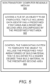
- FIG. 5 there is shown a block diagram of an example non-transitory computer readable medium 500 on which is stored machine readable instructions that are to cause a processor to fabricate an object having a predefined first area 204 and a predefined second area 206 to improve impact resistance of the fabricated object.
- the example non-transitory computer readable medium 500 depicted in FIG. 5 may include additional features and that some of the features described herein may be removed and/or modified without departing from a scope of the object 500.
- the description of the non-transitory computer readable medium 500 is made with reference to FIGS. 1-4 .
- the machine-readable storage medium 500 may be an electronic, magnetic, optical, or other physical storage device that contains or stores executable instructions.
- the machine-readable storage medium 500 may be, for example, Random Access memory (RAM), an Electrically Erasable Programmable Read-Only Memory (EEPROM), a storage device, an optical disc, and the like.
- the non-transitory machine-readable storage medium 500 has stored thereon machine readable instructions 502 and 504 that a processor, e.g., the processor 102, executes.
- the machine readable instructions 502 cause the processor to access a file of an object 400 to be fabricated.
- the file includes data identifying a predefined first area 204 and a predefined second area 206 encompassed by the predefined first area 204 in the object 400.
- the data indicates that the predefined first area 204 is to be solidified to a higher degree of solidification than the predefined second area 206.
- the machine readable instructions 504 cause the processor to control a fabricating system 104 to fabricate the object 400 to include the predefined first area 204 formed of build material that is solidified to a higher degree than build material in the predefined second area 206 through fabrication of layers of build material 202.
- the predefined second area 206 may not be fully solidified, the predefined second area 206 has a lower fracture toughness than the predefined first area 204.
- the predefined second area 206 more readily propagates a crack in the object 400 than the predefined first area 204, which may improve impact resistance of the object 400.
- the predefined second area 206 is shaped and is positioned to maximize damage reduction to the object.
Description
- In three-dimensional (3D) printing, an additive printing process is often used to make three-dimensional solid parts from a digital model. Some 3D printing techniques are considered additive processes because they involve the application of successive layers or volumes of a build material, such as a powder or powder-like build material, to an existing surface (or previous layer). 3D printing often includes solidification of the build material, which for some materials may be accomplished through use of heat and/or a chemical binder.
WO 2016/189312 A2 discloses a method for forming a three-dimensional object by depositing successive layers of powder onto a surface and selectively bonding the powder to form the three-dimensional object. The three-dimensional object is formed such that it has a porous exterior skin and an interior volume of powder, wherein the porous exterior skin has a greater density than the interior volume of powder.
A similar method is also known fromDE 100 42 132 B4 , which discloses the preamble of the independent claims.
WO 2018/074993 A1 discloses a method of generating a three-dimensional object with an additive manufacturing system, wherein a fusing agent is selectively deposited onto a portion of a build material. Energy from a bulk-fusion energy source is applied to fuse at least a portion of the build material where the fusing agent is deposited. In addition, energy from a focused energy source is applied to one or more localized areas. - Features of the present invention are illustrated by way of example and not limited in the following figure(s), in which like numerals indicate like elements, in which:
-
FIG. 1 shows a block diagram of an example apparatus that may cause a second area having a lower degree of solidification to be formed in a fabricated object to improve impact resistance of the fabricated object; -
FIG. 2 shows a block diagram of another example apparatus that may cause a second area having a lower degree of solidification to be formed in a fabricated object to improve impact resistance of the fabricated object; -
FIG. 3 depicts a flow diagram of an example method to cause a second area to be formed in a fabricated object to improve impact resistance of the fabricated object; -
FIG. 4 shows a cross-sectional side view of an example object fabricated to include a predefined first area and predefined second areas; and -
FIG. 5 shows a block diagram of an example non-transitory computer readable medium on which is stored machine readable instructions that are to cause a processor to fabricate an object having a predefined first area and a predefined second area to improve impact resistance of the fabricated object. - The present invention provides an apparatus according to claim 1, a method according to claim 7 and a non-transitory computer readable medium according to claim 12. Examples thereof are detailed in the dependent claims. Disclosed herein are apparatuses and methods that are implemented to fabricate a three-dimensional (3D) object with a first area surrounding a second area, in which the second area is formed of the same build material as the first area and is solidified to a lower degree of solidification than the first area. The 3D object is formed through formation of the first area and second area in multiple layers of the build material. As discussed herein, the 3D object may be fabricated through any of a number of various fabrication processes. In addition, the second area may be fabricated without being solidified or may be partially solidified. In this regard, the term "unsolidified" may be defined herein as being completely unsolidified, being partially solidified, being under-solidified, a fully coagulated state with weaker bonding between particles, or the like. The second area may be solidified to a lower degree than the first area through, for instance, incomplete thermal curing, weaker less binding agent, etc.
- As the second area has a lower density than the first area, the second area has a lower fracture toughness than the first area. As such, in instances in which an object formed of the first area and the second area is hit with a sufficient force to cause a crack to occur in the object, the energy from the hit may be forced to go through the second area. In addition, because the second area has a lower fracture toughness than the first area, the energy from the hit may propagate through the second area more readily because propagating through the second area may take less energy than propagating through the first area. According to examples, the second area may be designed to guide the propagation of energy, e.g., crack formation, to detour directions and dead-ends in the first area. Thus, for instance, the second area may be shaped and may be located strategically within the first area to cause cracks to be propagated to predefined first areas, for instance, that are in interior locations of the object. In this manner, the object may be fabricated with greater impact resistance.
- In some examples, the apparatuses and methods disclosed herein may fabricate 3D objects with a third area that is encompassed by the first area, in which the third area may be solidified to a lower degree of solidification than the first area and the second area. In these examples, the third area may be outside of the second area or may be encompassed within the second area. In any regard, the third area may have a lower density than the second area and thus, energy from an impact on an object containing the first area, the second area, and the third area may propagate through the third area more readily than the first area or the second area. In examples, the third area may also be shaped and may be located strategically within the first area (and/or the second area) to cause cracks to be propagated to predefined first areas, for instance, that are in interior locations of the object. In this manner, the object may be fabricated with greater impact resistance. The apparatuses and methods disclosed herein may fabricate 3D objects with additional areas that are encompassed by the first area, in which the additional areas may be solidified to lower degrees of solidification than the first area, the second area, and the third area. Accordingly, although particular reference is made herein to a first area and a second area, it should be understood that additional areas having additional degrees of solidification may be formed in the fabricated 3D objects without departing from a scope of the present disclosure.
- Before continuing, it is noted that as used herein, the terms "includes" and "including" mean, but is not limited to, "includes" or "including" and "includes at least" or "including at least." The term "based on" means "based on" and "based at least in part on."
- Reference is first made to
FIGS. 1 and2 .FIG. 1 shows a block diagram of an example apparatus 100 that is to cause a second area having a lower degree of solidification to be formed in a fabricated object to improve impact resistance of the fabricated object.FIG. 2 shows a block diagram of another example apparatus 200, such as a 3D fabrication system, that is also to cause a second area having a lower degree of solidification to be formed in a fabricated object to improve impact resistance of the fabricated object. It should be understood that the example apparatuses 100 and 200 depicted inFIGS. 1 and2 may include additional features and that some of the features described herein may be removed and/or modified without departing from the scopes of the apparatuses 100 and 200. - Generally speaking, the apparatuses 100, 200 depicted in
FIGS. 1 and2 are each a 3D fabricating system. The apparatuses 100, 200 may also be termed a 3D printer, a 3D fabricator, or the like. Generally speaking, the 3D apparatuses 100, 200 are implemented to fabricate 3D objects from build material. The build material 202 is a material that is applied in layers and selectively solidified. The build material 202 includes particles of material (e.g., in the form of a powder) or a paste material. The build material 202 has been shown inFIG. 2 as being partially transparent to enable afirst area 204 and asecond area 206 to be visible. It should thus be understood that the build material 202 may not be transparent, but instead, may be opaque. - In instances in which the build material 202 includes particles of material, the particles of build material may include any material suitable for melting and selective solidification, including, but not limited to, a polymer, a plastic, a ceramic, a nylon, a metal, combinations thereof, or the like, and may be in the form of a powder or a powder-like material. Additionally, the particles may be formed to have dimensions, e.g., widths, diameters, or the like, that are generally between about 5 µm and about 100 µm. In other examples, the particles may have dimensions that are generally between about 30 µm and about 60 µm. The particles may have any of multiple shapes, for instance, as a result of larger particles being ground into smaller particles. In some examples, the powder may be formed from, or may include, short fibers that may, for example, have been cut into short lengths from long strands or threads of material.
- The apparatuses 100, 200 include a
processor 102 that respectively controls operations of the apparatuses 100, 200. Theprocessor 102 may be a semiconductor-based microprocessor, a central processing unit (CPU), an application specific integrated circuit (ASIC), a field-programmable gate array (FPGA), and/or other suitable hardware device. The apparatuses 100, 200 also include a fabricatingsystem 104 that theprocessor 102 controls in the fabrication of 3D objects. Theprocessor 102 controls the fabricatingsystem 104 to selectively solidify a predefinedfirst area 204 of the build material 202 to have a higher degree of solidification than a predefined second area 206 (e.g., less than fully solidified, partially solidified, in powder form, or the like). - The apparatuses 100, 200 also include a
memory 110 that has stored thereon machinereadable instructions 112 and 114 (which may also be termed computer readable instructions) that theprocessor 102 may execute. Thememory 110 may be an electronic, magnetic, optical, or other physical storage device that contains or stores executable instructions. Thememory 110 may be, for example, Random Access memory (RAM), an Electrically Erasable Programmable Read-Only Memory (EEPROM), a storage device, an optical disc, and the like. Thememory 110, which may also be referred to as a computer readable storage medium, may be a non-transitory machine-readable storage medium, where the term "non-transitory" does not encompass transitory propagating signals. - The
processor 102 is there to fetch, decode, and execute theinstructions 112 to control the fabricatingsystem 104 to spread a layer of build material 202 as part of an object fabrication process. For instance, the fabricating system104 may include arecoater 208 that may be controlled to spread a layer of build material 202 on abuild platform 210, which may be in a build chamber within which 3D objects may be fabricated from the build material 202 provided in respective layers on thebuild platform 210. Particularly, thebuild platform 210 may be provided in a build chamber of a 3D fabrication system and may be moved downward as features of a 3D object are formed in successive layers of the build material 202. Although not shown, the build material 202 may be supplied between therecoater 208 and thebuild platform 210 and therecoater 208 may be moved in a direction represented by thearrow 212 across thebuild platform 210 to spread the build material 202 into a layer. - The
processor 102 is there to fetch, decode, and execute theinstructions 114 to control the fabricatingsystem 104 to selectively solidify afirst area 204 of the layer to a higher degree of solidification than a predefinedsecond area 206 encompassed by thefirst area 204. For instance, theprocessor 102 accesses a file that includes data identifying thefirst area 204 and the predefinedsecond area 206. Thesecond area 206 is predefined in that the data in the file specifies the dimensions, e.g., shape, and location at which thesecond area 206 is to be formed within thefirst area 204. The data in the file specifies also the level to which the build material 202 in thesecond area 206 is to be solidified. For instance, the data specifies that the build material 202 may be completely unsolidified, may be solidified to a certain percentage that is less than 100%, or other levels therebetween. - The
processor 102 may repeat execution of theinstructions first areas 204 andsecond areas 206 until, for instance, the object is fabricated. In addition, thesecond areas 206 in adjacent layers may be connected to each other such that thesecond areas 206 may form a feature that extends in three dimensions and across multiple layers. Theprocessor 102 also controls the fabricatingsystem 104 to form a plurality ofsecond areas 206 in the fabricated object, in which thesecond areas 206 are positioned within the object to maximize damage reduction to the object caused by impact on the object, e.g., maximize impact resistance. In addition, thesecond area 206 is formed of the same build material 202 as thefirst area 204, but may have greater porosity, may be weaker, etc., than thefirst area 204. - According to examples, the fabricating
system 104 may include an energy supplying component for selectively solidifying the build material 202 through application of solidifying energy onto the build material 202. The solidifying energy may be in the form of light (visible, infrared, ultraviolet, or the like), in the form of heat, in the form of electromagnetic energy, combinations thereof, or the like. By way of example, the energy supplying component may include a laser beam source, a heating component, or the like. In some examples, theprocessor 102 may control the energy supplying component to melt or sinter the build material 202 in thefirst area 204. In addition, as the build material 202 particles in thefirst area 204 are heated, at least some of the particles in thesecond area 206 may melt (or sinter) and fuse together through thermal bleed from the particles in thefirst area 204. In some examples, the width of thesecond area 206 may be sized based on an intended degree of solidification of the particles in thesecond area 206. For instance, the width of thesecond area 206 may be of sufficiently large size to enable a portion of thesecond area 206 to remain unsolidified following receipt of heat through thermal bleed from the particles in thefirst area 204. By way of particular example, the width of thesecond area 206 may be defined based on an amount of heat predicted to occur through thermal bleed and the effects of that heat on the solidification of the particles in thesecond area 206, e.g., the width of thesecond area 206 may be optimized to control the degree of solidification occurring on the particles in thesecond area 206. - However, in other examples, the build material 202 particles in the
second area 206 may be solidified to a certain level that is greater than a level that may be achieved through absorption of heat through thermal bleeding of the build material 202 particles in thefirst area 204. In these examples, theprocessor 102 may control the energy supplying component to apply a first amount of solidifying energy onto the particles in thefirst area 204 and to apply a second amount of solidifying energy onto the particles in thesecond area 206, in which the second amount of solidifying energy is lower than the first amount of solidifying energy. Thus, for instance, the build material 202 in thesecond area 206 is solidified to a lower degree of solidification than the build material 202 in thefirst area 204. - According to examples in which the build material 202 includes particles and the fabricating
system 104 includes a heating component to apply solidifying energy onto the layer of build material 202, theprocessor 102 may control the heating component, e.g., a laser beam source, to selectively apply solidifying energy onto the layer, as represented by thearrow 220. That is, theprocessor 102 may control the heating component to selectively apply solidifying energy onto the build material 202 particles located in thefirst area 204 of the layer. Additionally, theprocessor 102 may control the heating component to avoid application of solidifying energy onto the build material 202 particles located in thesecond area 206 of the layer. However, as the build material 202 particles in thefirst area 204 are heated, at least some of the particles in thesecond area 206 may melt or sinter and through receipt of heat from thermal bleed from the particles in thefirst area 204. - According to examples in which the build material 202 includes particles and the fabricating
system 104 includes a solidifying agent delivery component that theprocessor 102 may control to selectively apply solidifying agent onto the layer, as represented by thearrow 222. The solidifying agent may be an ink, a binder, or the like. The solidifying agent delivery component may be a fluid delivery device, such as a printhead. In some examples, the solidifying agent may be a chemical binder that may bind particles on which the solidifying agent is deposited to bind together. In other examples, the solidifying agent may be a liquid, such as an ink, a pigment, a dye, or the like, that may enhance absorption of energy. In either of these examples, theprocessor 102 may control the solidifying agent delivery component to deliver the solidifying agent in the form of droplets onto selected areas of the layer such that the droplets of solidifying agent may be dispersed on the particles and within interstitial spaces between the particles in the selected areas. - The fabricating
system 104 may also include an energy supply component that may supplyenergy 220 at a level that is insufficient to cause the particles upon which the solidifying agent has not been deposited to remain below the melting point temperature of the particles. In addition, the droplets of solidifying agent may be supplied at a sufficient density onto the particles in thefirst area 204, e.g., contone level, to enhance absorption of sufficient energy to cause the temperature of the particles on which the solidifying agent has been deposited to increase to a level that is above a melting point temperature of the particles. - In examples in which the build material 202 particles in the
second area 206 are to remain completely unsolidified or lightly solidified, theprocessor 102 may control the solidifying agent delivery component to deliver the solidifying agent onto the build material 202 particles located in thefirst area 204 without depositing the solidifying agent onto the build material 202 particles located in thesecond area 206. In addition, theprocessor 102 may control the energy supply component to supplyenergy 220 onto the layer of build material 202 particles, which may cause the particles in thefirst area 204 to melt or sinter and subsequently fuse together. For instance, after the particles have melted or sintered, the particles may fuse together as the particles are cooled. In these examples, at least some of the build material 202 particles in thesecond area 206 may melt or sinter through receipt of heat from the build material 202 particles in thefirst area 204 and subsequently fuse together. - However, in other examples, the build material 202 particles in the
second area 206 may be solidified to a certain level that is greater than a level that may be achieved through absorption of heat through thermal bleeding of the build material 202 particles in thefirst area 204. In these examples, theprocessor 102 may control the solidifying agent delivery component to deliver solidifying agent onto the build material 202 particles located in thesecond area 206 in a smaller concentration level than the solidifying agent delivered onto the build material 202 particles located in thefirst area 204. In addition, theprocessor 102 may control the energy supply component to supplyenergy 220 onto the layer of build material 202 particles, which may cause the particles in thefirst area 204 to melt or sinter and some of the particles in thesecond area 206 to melt or sinter. The melted or sintered particles may become solidified with neighboring particles as the melted or sintered particles cool. Thus, for instance, thesecond area 206 may be partially solidified. - According to examples, the fabricating
system 104 may include a detailing agent delivery component to selectively deliver a detailing agent onto the build material 202 layer. The detailing agent, which may also be termed a cooling agent, a defusing agent, or the like, may cool the particles on which the detailing agent has been deposited to reduce a level of melting or sintering of the particles. Theprocessor 102 may control the detailing agent delivery component to deliver detailing agent onto particles in thesecond area 206 to reduce melting or sintering of those particles and to thus, maintain the particles in thesecond area 206 in an unsolidified or a partially solidified state. By way of particular example, theprocessor 102 may control the detailing agent delivery component to deliver detailing agent onto the particles in thesecond area 206 in instances in which thesecond area 206 has a sufficiently small dimension that thermal bleed from thefirst area 204 may cause the particles in thesecond area 206 to melt or sinter and solidify without the detailing agent. That is, the detailing agent may be applied to cause the particles in thesecond area 206 to solidify to a lower degree of solidification than the particles in thefirst area 204. - According to examples, the fabricating
system 104 may be moved across thebuild platform 210 as indicated by thearrow 216 to be positioned over multiple areas of the build material 202 layer. In this regard, the fabricatingsystem 104 may selectively solidify multiple areas of the build material 202 layer. For instance, the fabricatingsystem 104 may be supported on a carriage that is to move in thedirections 216. In some examples, therecoater 208 may be provided on the same carriage. - In other examples, instead of the
memory 110, the apparatus 100, 200 may include hardware logic blocks that may perform functions similar to theinstructions instructions processor 102 may implement the hardware logic blocks and/or execute theinstructions - Various manners in which the
processor 102 may operate are discussed in greater detail with respect to themethod 300 depicted inFIG. 3 . Particularly,FIG. 3 depicts a flow diagram of anexample method 300 to cause a second area to be formed in a fabricated object to improve impact resistance of the fabricated object. It should be understood that themethod 300 depicted inFIG. 3 may include additional operations and that some of the operations described therein may be removed and/or modified without departing from scope of themethod 300. The description of themethod 300 is made with reference to the features depicted inFIGS. 1 and2 for purposes of illustration. - At
block 302, theprocessor 102 accesses a file of an object to be fabricated, for instance, by the apparatus 100, 200. The file includes data identifying a predefinedfirst area 204 and a predefinedsecond area 206 within thefirst area 204. The predefinedfirst area 204 may be an area of the object that is to be fully solidified and the predefinedsecond area 206 is an area of the object that is to be partially solidified or unsolidified. - At
block 304, theprocessor 102 controls a fabricatingsystem 104 to selectively solidify build material 202 in the predefinedfirst area 204 to a higher degree of solidification than the build material 202 in the predefinedsecond area 206. As discussed herein, theprocessor 102 controls the fabricatingsystem 104 in any of a number of different manners to solidify the build material 202 in the predefinedfirst area 204 to a higher degree of solidification than the build material 202 in the predefinedsecond area 206. In other words, theprocessor 102 controls the fabricatingsystem 104 to form the predefinedsecond area 206 to be less solidified, e.g., more porous, than the predefinedfirst area 204. As a result, the predefinedsecond area 206 has a lower fracture toughness than the predefinedfirst area 204, which causes the predefinedsecond area 206 to propagate a crack in the object more readily than the predefinedfirst area 204. - By way of example, when an object formed of the predefined
first area 204 and the predefinedsecond area 206 is hit with a sufficient force to cause a crack to occur in the object, the energy from the hit may be forced to go through the predefinedsecond area 206. Because the predefinedsecond area 206 has a lower fracture toughness than the predefinedfirst area 204, the energy may propagate through the predefinedsecond area 206 because propagating through the predefinedsecond area 206 may take less energy than propagating through the predefinedfirst area 204. In one regard, the predefinedsecond area 206 may be designed to guide the propagation of energy, e.g., crack formation, to detour directions and dead-ends in the predefinedfirst area 204. Thus, for instance, the predefinedsecond area 206 may have shapes and may be located strategically within the predefinedfirst area 204 to cause cracks to be propagated to predefinedfirst areas 204 that are in interior locations of the object. In this manner, the object may be able to withstand harder hits without causing external locations of the object to crack. - The shape and the location of the predefined
second area 206 is determined and the predefinedsecond area 206 is formed in the object to maximize damage reduction to the object caused by an impact onto the object. The shape and location of the predefinedsecond area 206 is based upon, for instance, the shape of the object, the build material used to fabricate the object, the fabrication process implemented, the intended level of impact resistance, or the like. In addition or in other examples, the shape and location of the predefinedsecond area 206 is determined through testing of various shapes and locations and determining a shape and location that results in the maximum damage reduction to the object. In any regard, the determined shape and location of the predefinedsecond area 206 may be stored in the file as data pertaining to the fabrication of the object. - Some or all of the operations set forth in the
method 300 are included as utilities, programs, or subprograms, in any desired computer accessible medium. In addition, themethod 300 is embodied by computer programs, which may exist in a variety of forms both active and inactive. For example, they exist as machine readable instructions, including source code, object code, executable code or other formats. Any of the above is there to be embodied on a non-transitory computer readable storage medium. - Examples of non-transitory computer readable storage media include computer system RAM, ROM, EPROM, EEPROM, and magnetic or optical disks or tapes. It is therefore to be understood that any electronic device capable of executing the above-described functions may perform those functions enumerated above.
- Turning now to
FIG. 4 , there is shown a cross-sectional side view of anexample object 400 fabricated to include a predefinedfirst area 204 and predefinedsecond areas 206. It should be understood that theexample object 400 depicted inFIG. 4 may include additional features and that some of the features described herein may be removed and/or modified without departing from a scope of theobject 400. - As shown in
FIG. 4 , theobject 400 is fabricated to include predefinedsecond areas 206 that have any of a plurality of a variety of shapes and are positioned in any of a plurality of locations within the predefinedfirst area 204. For instance, the predefinedsecond areas 206 may extend horizontally, vertically, or diagonally. The predefinedsecond areas 206 may additionally have elongated shapes, X-shapes, Y-shapes, T-shapes, or the like. As a further example, the predefinedsecond areas 206 may form a lattice structure, may be connected to each other, or the like. In any regard, thesecond areas 206 have shapes and are positioned to maximize damage reduction to theobject 400 caused by an impact onto the object. - With reference now to
FIG. 5 , there is shown a block diagram of an example non-transitory computerreadable medium 500 on which is stored machine readable instructions that are to cause a processor to fabricate an object having a predefinedfirst area 204 and a predefinedsecond area 206 to improve impact resistance of the fabricated object. It should be understood that the example non-transitory computerreadable medium 500 depicted inFIG. 5 may include additional features and that some of the features described herein may be removed and/or modified without departing from a scope of theobject 500. The description of the non-transitory computerreadable medium 500 is made with reference toFIGS. 1-4 . - The machine-
readable storage medium 500 may be an electronic, magnetic, optical, or other physical storage device that contains or stores executable instructions. The machine-readable storage medium 500 may be, for example, Random Access memory (RAM), an Electrically Erasable Programmable Read-Only Memory (EEPROM), a storage device, an optical disc, and the like. - The non-transitory machine-
readable storage medium 500 has stored thereon machinereadable instructions processor 102, executes. The machinereadable instructions 502 cause the processor to access a file of anobject 400 to be fabricated. The file includes data identifying a predefinedfirst area 204 and a predefinedsecond area 206 encompassed by the predefinedfirst area 204 in theobject 400. In addition, the data indicates that the predefinedfirst area 204 is to be solidified to a higher degree of solidification than the predefinedsecond area 206. - The machine
readable instructions 504 cause the processor to control a fabricatingsystem 104 to fabricate theobject 400 to include the predefinedfirst area 204 formed of build material that is solidified to a higher degree than build material in the predefinedsecond area 206 through fabrication of layers of build material 202. As discussed herein, as the predefinedsecond area 206 may not be fully solidified, the predefinedsecond area 206 has a lower fracture toughness than the predefinedfirst area 204. As a result, the predefinedsecond area 206 more readily propagates a crack in theobject 400 than the predefinedfirst area 204, which may improve impact resistance of theobject 400. As also discussed herein, the predefinedsecond area 206 is shaped and is positioned to maximize damage reduction to the object. - What has been described and illustrated herein is an example of the disclosure along with some of its variations. The terms, descriptions and figures used herein are set forth by way of illustration only and are not meant as limitations. Many variations are possible within the scope of the disclosure, which is defined by the following claims in which all terms are meant in their broadest reasonable sense unless otherwise indicated.
Claims (12)
- An apparatus (100, 200) comprising:a fabricating system (104);a processor (102); anda memory (110) on which are stored machine readable instructions (112, 114) that when executed by the processor (102), cause the processor (102) to:control the fabricating system (104) to spread a first layer of build material (202) as part of an object fabrication process, the build material (202) comprising particles or a paste; andcontrol the fabricating system (104) to selectively solidify a first area (204) of the first layer to a higher degree of solidification than a predefined second area (206) encompassed by the first area (204), wherein the predefined second area (206) has a lower fracture toughness than the first area (204) to propagate a crack in the object (400) more readily than the first area (204),wherein the instructions (112, 114) are further to cause the processor (102) to:control the fabricating system (104) to form a plurality of predefined second areas (206) in the object (400), wherein the plurality of predefined second areas (206) are positioned within the object (400) to maximize damage reduction to the object (400) caused by an impact onto the object (400), characterized in thatthe locations of the predefined second areas (206) are based upon a shape of the object (400), the build material (202) used to fabricate the object (400), a fabrication process implemented and an intended level of impact resistance and/or wherein the locations of the predefined second areas (206) have been determined through testing of various locations and determining locations that result in the maximum damage reduction to the object (400).
- The apparatus (100, 200) of claim 1, wherein the instructions (112, 114) are further to cause the processor (102) to:control the fabricating system (104) to spread a second layer of build material (202); andcontrol the fabricating system (104) to selectively solidify a first area (204) in the second layer of the build material (202) to a higher degree of solidification than a predefined second area (206) within the solidified second layer, the predefined second area (206) in the second layer being connected to the predefined second area (206) in the first layer.
- The apparatus (100, 200) of claim 1, wherein the build material (202) comprises particles, and wherein to control the fabricating system (104) to selectively solidify the first area (204), the instructions (112, 114) are further to cause the processor (102) to:
control the fabricating system (104) to apply solidifying energy (220) onto the first layer, wherein the solidifying energy (220) is to cause the particles in the first area (204) to melt or sinter and subsequently solidify, wherein at least some of the particles in the predefined second area (206) are to melt or sinter through thermal bleed from the particles in the first area (204) and subsequently solidify to a lower degree of solidification than the first area (204). - The apparatus (100, 200) of claim 1, wherein the build material (202) comprises particles, and wherein to control the fabricating system (104) to selectively solidify the first area (204) to a higher degree of solidification than the predefined second area (206) encompassed by the first area (204), the instructions (112, 114) are further to cause the processor (102) to:control the fabricating system (104) to deposit a solidifying agent (222) onto the particles in the first area (204) of the first layer at a first coverage level;control the fabricating system (104) to deposit the solidifying agent (222) onto the particles in the predefined second area (206) of the first layer at a second coverage level, wherein the second coverage level is lower than the first coverage level; andcontrol the fabricating system (104) to apply solidifying energy (220) onto the first layer, wherein the solidifying energy (220) is to cause the particles in the first area (204) to melt or sinter and subsequently solidify and to cause the particles in the predefined second area (206) to melt or sinter and subsequently solidify to a lower degree of solidification than the particles in the first area (204).
- The apparatus (100, 200) of claim 1, wherein the build material (202) comprises particles, and wherein to control the fabricating system (104) to selectively solidify the first area (204), the instructions (112, 114) are further to cause the processor (102) tocontrol the fabricating system (104) to deposit a detailing agent onto the particles in the predefined second area (206); andcontrol the fabricating system (104) to apply solidifying energy (220) onto the first layer, wherein the solidifying energy (220) is to cause the particles in the first area (204) to melt or sinter and wherein the detailing agent is to reduce a level of melting or sintering of the particles in the predefined second area (206) caused through application of the solidifying energy (220) onto the first layer.
- The apparatus (100, 200) of claim 1, wherein instructions (112, 114) are further to cause the processor (102) to:control the fabricating system (104) to apply a first amount of solidifying energy (220) onto the first area (204); andcontrol the fabricating system (104) to apply a second amount of solidifying energy (220) onto the predefined second area (206), the second amount of solidifying energy (220) being lower than the first amount of solidifying energy (220).
- A method (300) comprising:accessing, by a processor (102), a file of an object (400) to be fabricated, the file including data identifying a predefined first area (204) and a predefined second area (206) within the predefined first area (204), the predefined second area (206) to be partially solidified or remain unsolidified; andcontrolling, by the processor (102), a fabricating system (104) to spread a first layer of build material (202) as part of an object fabrication process, the build material (202) comprising particles or a paste; and controlling the fabricating system (104) to selectively solidify build material (202) in the predefined first area (204) to a higher degree of solidification than the build material (202) in the predefined second area (206), the predefined second area (206) having a lower fracture toughness than the predefined first area (204) to more readily propagate a crack in the object (400) than the predefined first area,the method (300) further comprising:
controlling the fabricating system (104) to form a plurality of predefined second areas (206) in the object (400), wherein the plurality of predefined second areas (206) are positioned within the object (400) to maximize damage reduction to the object (400) caused by an impact onto the object (400), characterized in that the locations of the predefined second areas (206) are based upon a shape of the object (400), the build material (202) used to fabricate the object (400), a fabrication process implemented and an intended level of impact resistance and/or wherein the locations of the predefined second areas (206) have been determined through testing of various locations and determining locations that result in the maximum damage reduction to the object (400). - The method (300) of claim 7, wherein the build material (202) comprises particles, the method (300) further comprising:
controlling the fabricating system (104) to apply solidifying energy (220) to cause the particles in the predefined first area (204) to melt or sinter and subsequently solidify, wherein at least some of the particles in the predefined second area (206) are to melt or sinter through thermal bleed from the particles in the predefined first area (204) and subsequently solidify to a lower degree of solidification than the predefined first area (204). - The method (300) of claim 7, wherein the build material (202) comprises particles, the method (300) further comprising:controlling the fabricating system (104) to deposit a solidifying agent (222) onto the particles in the predefined first area (204) at a first coverage level;controlling the fabricating system (104) to deposit the solidifying agent (222) onto the particles in the predefined second area (206) at a second coverage level, wherein the second coverage level is lower than the first coverage level; andcontrolling the fabricating system (104) to apply solidifying energy (220) that is to cause the particles in the predefined first area (204) to melt or sinter and to cause some of the particles in the predefined second area (206) to melt or sinter and subsequently partially solidify to a lower degree of solidification than the particles in the predefined first area (204).
- The method (300) of claim 7, wherein the build material (202) comprises particles, and wherein the method (300) further comprises:controlling the fabricating system (104) to deposit a detailing agent onto the particles in the predefined second area (206); andcontrolling the fabricating system (104) to apply solidifying energy (220) that is to cause the particles in the predefined first area (204) to melt or sinter and wherein the detailing agent is to reduce a level of melting or sintering of the particles in the predefined second area (206) caused through application of the solidifying energy (220) onto the particles in the predefined second area (206).
- The method (300) of claim 7, further comprising:controlling the fabricating system (104) to apply a first amount of solidifying energy (220) to form the predefined first area (204); andcontrolling the fabricating system (104) to apply a second amount of solidifying energy (220) to form the predefined second area (206), the second amount of solidifying energy (220) being lower than the first amount of solidifying energy (220).
- A non-transitory computer readable medium (500) on which is stored machine readable instructions (502, 504) that when executed by a processor (102), cause the processor (102) to:access a file of an object (400) to be fabricated, the file including data identifying a predefined first area (204) and a predefined second area (206) encompassed by the predefined first area (204), the predefined first area (204) to be solidified to a higher degree of solidification than the predefined second area (206); and control a fabricating system (104) to spread a first layer of build material (202) as part of an object fabrication process, the build material (202) comprising particles or a paste; andcontrol the fabricating system (104) to fabricate the object (400) to include the predefined first area (204) formed of build material (202) that is solidified to a higher degree than build material (202) in the predefined second area (206) through fabrication of layers of the build material (202), the predefined second area (206) having a lower fracture toughness than the predefined first area (204) to more readily propagate a crack in the object (400) than the predefined first area (204),wherein the instructions (502, 504) are further to cause the processor (102) to:
control the fabricating system (104) to form a plurality of predefined second areas (206) in the object (400), wherein the plurality of predefined second areas (206) are positioned within the object (400) to maximize damage reduction to the object (400) caused by an impact onto the object (400), characterized in that the locations of the predefined second areas (206) are based upon a shape of the object (400), the build material (202) used to fabricate the object (400), a fabrication process implemented and an intended level of impact resistance and/or wherein the locations of the predefined second areas (206) have been determined through testing of various locations and determining locations that result in the maximum damage reduction to the object (400).
Applications Claiming Priority (1)
| Application Number | Priority Date | Filing Date | Title |
|---|---|---|---|
| PCT/US2018/030297 WO2019212517A1 (en) | 2018-04-30 | 2018-04-30 | Fabrication of objects having different degree of solidification areas |
Publications (3)
| Publication Number | Publication Date |
|---|---|
| EP3749502A1 EP3749502A1 (en) | 2020-12-16 |
| EP3749502A4 EP3749502A4 (en) | 2021-09-01 |
| EP3749502B1 true EP3749502B1 (en) | 2023-03-22 |
Family
ID=68386542
Family Applications (1)
| Application Number | Title | Priority Date | Filing Date |
|---|---|---|---|
| EP18917272.9A Active EP3749502B1 (en) | 2018-04-30 | 2018-04-30 | Fabrication of objects having different degree of solidification areas |
Country Status (4)
| Country | Link |
|---|---|
| US (1) | US11400655B2 (en) |
| EP (1) | EP3749502B1 (en) |
| CN (1) | CN112272607B (en) |
| WO (1) | WO2019212517A1 (en) |
Families Citing this family (1)
| Publication number | Priority date | Publication date | Assignee | Title |
|---|---|---|---|---|
| WO2021118535A1 (en) | 2019-12-10 | 2021-06-17 | Hewlett-Packard Development Company, L.P. | Three-dimensional (3d) printed objects with fracture channels |
Family Cites Families (26)
| Publication number | Priority date | Publication date | Assignee | Title |
|---|---|---|---|---|
| US7300619B2 (en) | 2000-03-13 | 2007-11-27 | Objet Geometries Ltd. | Compositions and methods for use in three dimensional model printing |
| DE10042132B4 (en) | 2000-08-28 | 2012-12-13 | Cl Schutzrechtsverwaltungs Gmbh | Selective surface layer melting |
| US8439998B2 (en) | 2004-12-06 | 2013-05-14 | Sunrex Kogyo Co., Ltd. | Manufacturing method of metal product and metal product |
| DK2052693T4 (en) * | 2007-10-26 | 2021-03-15 | Envisiontec Gmbh | Process and free-form manufacturing system to produce a three-dimensional object |
| US8272816B2 (en) | 2009-05-12 | 2012-09-25 | TDY Industries, LLC | Composite cemented carbide rotary cutting tools and rotary cutting tool blanks |
| EP2763840B1 (en) | 2011-10-07 | 2022-03-23 | Materialise NV | Additive manufacturing of tiled objects |
| FR2987293B1 (en) | 2012-02-27 | 2014-03-07 | Michelin & Cie | METHOD AND APPARATUS FOR REALIZING THREE-DIMENSIONAL OBJECTS WITH IMPROVED PROPERTIES |
| US10081136B2 (en) * | 2013-07-15 | 2018-09-25 | California Institute Of Technology | Systems and methods for additive manufacturing processes that strategically buildup objects |
| WO2015106844A1 (en) * | 2014-01-16 | 2015-07-23 | Hewlett-Packard Development Company L.P. | Build material profile |
| JP6353547B2 (en) | 2014-01-16 | 2018-07-04 | ヒューレット−パッカード デベロップメント カンパニー エル.ピー.Hewlett‐Packard Development Company, L.P. | 3D object generation |
| US9649690B2 (en) * | 2014-02-25 | 2017-05-16 | General Electric Company | System having layered structure and method of making the same |
| US9533485B2 (en) | 2014-03-28 | 2017-01-03 | Pratt & Whitney Canada Corp. | Compressor variable vane assembly |
| CN106716574B (en) | 2014-06-06 | 2020-10-16 | 东北大学 | Additive manufacturing of discontinuous fiber composites using magnetic fields |
| CN107073825B (en) | 2014-10-29 | 2019-08-06 | 惠普发展公司,有限责任合伙企业 | Three-dimensional (3D) Method of printing |
| GB201500607D0 (en) * | 2015-01-14 | 2015-02-25 | Digital Metal Ab | Additive manufacturing method, method of processing object data, data carrier, object data processor and manufactured object |
| GB201508996D0 (en) | 2015-05-26 | 2015-07-08 | Mfg Technology Ct The Ltd | A method for forming a three dimensional object |
| DE102015217469A1 (en) * | 2015-09-11 | 2017-03-16 | Eos Gmbh Electro Optical Systems | Method and device for producing a three-dimensional object |
| US20190039321A1 (en) | 2016-02-05 | 2019-02-07 | Stratasys Ltd. | Digitally-controlled three-dimensional printing using ring-opening metathesis polymerization |
| US20170297100A1 (en) * | 2016-04-14 | 2017-10-19 | Desktop Metal, Inc. | Method for fabricating an interface layer to separate binder jetted objects from support structures |
| CN109476076B (en) | 2016-07-27 | 2021-10-08 | 惠普发展公司,有限责任合伙企业 | Forming three-dimensional (3D) electronic components |
| US10800154B2 (en) * | 2016-10-17 | 2020-10-13 | Hewlett-Packard Development Company, L.P. | Hybrid fusion system |
| US10780528B2 (en) * | 2016-11-29 | 2020-09-22 | Honeywell International Inc. | Methods for residual stress reduction in additive manufacturing processes |
| JP6908705B2 (en) * | 2016-12-06 | 2021-07-28 | マークフォージド,インコーポレーテッド | Addition manufacturing by supplying heat bending material |
| US10589508B2 (en) * | 2016-12-15 | 2020-03-17 | General Electric Company | Additive manufacturing systems and methods |
| US20180257300A1 (en) * | 2017-03-09 | 2018-09-13 | Applied Materials, Inc. | Additive manufacturing with energy delivery system having rotating polygon and adjustment of angle of light path |
| US20200114426A1 (en) * | 2017-06-30 | 2020-04-16 | Siemens Aktiengesellschaft | An Additive Manufacturing Method for Precipitation-Hardened Superalloy Powdered Material |
-
2018
- 2018-04-30 CN CN201880092922.6A patent/CN112272607B/en active Active
- 2018-04-30 EP EP18917272.9A patent/EP3749502B1/en active Active
- 2018-04-30 WO PCT/US2018/030297 patent/WO2019212517A1/en unknown
- 2018-04-30 US US16/605,200 patent/US11400655B2/en active Active
Also Published As
| Publication number | Publication date |
|---|---|
| CN112272607B (en) | 2023-02-03 |
| WO2019212517A9 (en) | 2020-11-05 |
| US11400655B2 (en) | 2022-08-02 |
| CN112272607A (en) | 2021-01-26 |
| US20210323237A1 (en) | 2021-10-21 |
| WO2019212517A1 (en) | 2019-11-07 |
| EP3749502A4 (en) | 2021-09-01 |
| EP3749502A1 (en) | 2020-12-16 |
Similar Documents
| Publication | Publication Date | Title |
|---|---|---|
| KR102223986B1 (en) | Construction material particle lamination | |
| US11607842B2 (en) | Thermal supports for 3D features formed from particles | |
| KR101965519B1 (en) | Generating a three-dimensional object | |
| EP3429824B1 (en) | 3d print definition procedures | |
| US11660823B2 (en) | Unfused thermal support area in 3D fabrication systems | |
| CN109070463B (en) | Three-dimensional (3D) printing | |
| DE102018111517A1 (en) | Method for controlling distortion in 3D printing | |
| EP3749502B1 (en) | Fabrication of objects having different degree of solidification areas | |
| WO2019017886A1 (en) | Build unit for three-dimensional printer | |
| EP3888888B1 (en) | Porous sections with partially-fused build material particles | |
| US11504769B2 (en) | Controlled fiber orientation in additive manufactured parts | |
| EP3245041B1 (en) | Additive manufacturing | |
| TWI752744B (en) | Additive manufacturing system and method, and related non-transitory machine-readable storage medium | |
| US20220097309A1 (en) | Agent composition determination based on thermal values | |
| US20220083023A1 (en) | Orientation based 3d model section thickness determinations | |
| JP6730412B2 (en) | 3D object generation | |
| US20220332053A1 (en) | Management of printer control fluids | |
| CN113165272A (en) | Reagent recipe determination based on surface orientation of 3D model | |
| CN112272609A (en) | Thermal property control in a build material | |
| US20190039136A1 (en) | Fusing of metallic particles |
Legal Events
| Date | Code | Title | Description |
|---|---|---|---|
| STAA | Information on the status of an ep patent application or granted ep patent |
Free format text: STATUS: THE INTERNATIONAL PUBLICATION HAS BEEN MADE |
|
| PUAI | Public reference made under article 153(3) epc to a published international application that has entered the european phase |
Free format text: ORIGINAL CODE: 0009012 |
|
| STAA | Information on the status of an ep patent application or granted ep patent |
Free format text: STATUS: REQUEST FOR EXAMINATION WAS MADE |
|
| 17P | Request for examination filed |
Effective date: 20200911 |
|
| AK | Designated contracting states |
Kind code of ref document: A1 Designated state(s): AL AT BE BG CH CY CZ DE DK EE ES FI FR GB GR HR HU IE IS IT LI LT LU LV MC MK MT NL NO PL PT RO RS SE SI SK SM TR |
|
| AX | Request for extension of the european patent |
Extension state: BA ME |
|
| DAV | Request for validation of the european patent (deleted) | ||
| DAX | Request for extension of the european patent (deleted) | ||
| A4 | Supplementary search report drawn up and despatched |
Effective date: 20210802 |
|
| RIC1 | Information provided on ipc code assigned before grant |
Ipc: B29C 64/165 20170101AFI20210727BHEP Ipc: B29C 64/393 20170101ALI20210727BHEP Ipc: B22F 3/10 20060101ALI20210727BHEP Ipc: B33Y 50/02 20150101ALI20210727BHEP Ipc: B22F 10/20 20210101ALI20210727BHEP Ipc: B22F 10/30 20210101ALI20210727BHEP Ipc: B29C 64/153 20170101ALI20210727BHEP Ipc: B33Y 10/00 20150101ALI20210727BHEP Ipc: B33Y 30/00 20150101ALI20210727BHEP |
|
| STAA | Information on the status of an ep patent application or granted ep patent |
Free format text: STATUS: EXAMINATION IS IN PROGRESS |
|
| 17Q | First examination report despatched |
Effective date: 20220512 |
|
| GRAP | Despatch of communication of intention to grant a patent |
Free format text: ORIGINAL CODE: EPIDOSNIGR1 |
|
| STAA | Information on the status of an ep patent application or granted ep patent |
Free format text: STATUS: GRANT OF PATENT IS INTENDED |
|
| RIC1 | Information provided on ipc code assigned before grant |
Ipc: B22F 10/38 20210101ALI20221117BHEP Ipc: B22F 10/28 20210101ALI20221117BHEP Ipc: B29C 64/393 20170101ALI20221117BHEP Ipc: B22F 3/10 20060101ALI20221117BHEP Ipc: B33Y 50/02 20150101ALI20221117BHEP Ipc: B22F 10/20 20210101ALI20221117BHEP Ipc: B22F 10/30 20210101ALI20221117BHEP Ipc: B29C 64/153 20170101ALI20221117BHEP Ipc: B33Y 10/00 20150101ALI20221117BHEP Ipc: B33Y 30/00 20150101ALI20221117BHEP Ipc: B29C 64/165 20170101AFI20221117BHEP |
|
| INTG | Intention to grant announced |
Effective date: 20221216 |
|
| GRAS | Grant fee paid |
Free format text: ORIGINAL CODE: EPIDOSNIGR3 |
|
| GRAA | (expected) grant |
Free format text: ORIGINAL CODE: 0009210 |
|
| STAA | Information on the status of an ep patent application or granted ep patent |
Free format text: STATUS: THE PATENT HAS BEEN GRANTED |
|
| AK | Designated contracting states |
Kind code of ref document: B1 Designated state(s): AL AT BE BG CH CY CZ DE DK EE ES FI FR GB GR HR HU IE IS IT LI LT LU LV MC MK MT NL NO PL PT RO RS SE SI SK SM TR |
|
| REG | Reference to a national code |
Ref country code: GB Ref legal event code: FG4D |
|
| REG | Reference to a national code |
Ref country code: CH Ref legal event code: EP |
|
| REG | Reference to a national code |
Ref country code: IE Ref legal event code: FG4D |
|
| REG | Reference to a national code |
Ref country code: DE Ref legal event code: R096 Ref document number: 602018047639 Country of ref document: DE |
|
| REG | Reference to a national code |
Ref country code: AT Ref legal event code: REF Ref document number: 1555042 Country of ref document: AT Kind code of ref document: T Effective date: 20230415 |
|
| REG | Reference to a national code |
Ref country code: LT Ref legal event code: MG9D |
|
| REG | Reference to a national code |
Ref country code: NL Ref legal event code: MP Effective date: 20230322 |
|
| PG25 | Lapsed in a contracting state [announced via postgrant information from national office to epo] |
Ref country code: RS Free format text: LAPSE BECAUSE OF FAILURE TO SUBMIT A TRANSLATION OF THE DESCRIPTION OR TO PAY THE FEE WITHIN THE PRESCRIBED TIME-LIMIT Effective date: 20230322 Ref country code: NO Free format text: LAPSE BECAUSE OF FAILURE TO SUBMIT A TRANSLATION OF THE DESCRIPTION OR TO PAY THE FEE WITHIN THE PRESCRIBED TIME-LIMIT Effective date: 20230622 Ref country code: LV Free format text: LAPSE BECAUSE OF FAILURE TO SUBMIT A TRANSLATION OF THE DESCRIPTION OR TO PAY THE FEE WITHIN THE PRESCRIBED TIME-LIMIT Effective date: 20230322 Ref country code: LT Free format text: LAPSE BECAUSE OF FAILURE TO SUBMIT A TRANSLATION OF THE DESCRIPTION OR TO PAY THE FEE WITHIN THE PRESCRIBED TIME-LIMIT Effective date: 20230322 Ref country code: HR Free format text: LAPSE BECAUSE OF FAILURE TO SUBMIT A TRANSLATION OF THE DESCRIPTION OR TO PAY THE FEE WITHIN THE PRESCRIBED TIME-LIMIT Effective date: 20230322 |
|
| PGFP | Annual fee paid to national office [announced via postgrant information from national office to epo] |
Ref country code: DE Payment date: 20230321 Year of fee payment: 6 |
|
| REG | Reference to a national code |
Ref country code: AT Ref legal event code: MK05 Ref document number: 1555042 Country of ref document: AT Kind code of ref document: T Effective date: 20230322 |
|
| PG25 | Lapsed in a contracting state [announced via postgrant information from national office to epo] |
Ref country code: SE Free format text: LAPSE BECAUSE OF FAILURE TO SUBMIT A TRANSLATION OF THE DESCRIPTION OR TO PAY THE FEE WITHIN THE PRESCRIBED TIME-LIMIT Effective date: 20230322 Ref country code: NL Free format text: LAPSE BECAUSE OF FAILURE TO SUBMIT A TRANSLATION OF THE DESCRIPTION OR TO PAY THE FEE WITHIN THE PRESCRIBED TIME-LIMIT Effective date: 20230322 Ref country code: GR Free format text: LAPSE BECAUSE OF FAILURE TO SUBMIT A TRANSLATION OF THE DESCRIPTION OR TO PAY THE FEE WITHIN THE PRESCRIBED TIME-LIMIT Effective date: 20230623 Ref country code: FI Free format text: LAPSE BECAUSE OF FAILURE TO SUBMIT A TRANSLATION OF THE DESCRIPTION OR TO PAY THE FEE WITHIN THE PRESCRIBED TIME-LIMIT Effective date: 20230322 |
|
| PG25 | Lapsed in a contracting state [announced via postgrant information from national office to epo] |
Ref country code: SM Free format text: LAPSE BECAUSE OF FAILURE TO SUBMIT A TRANSLATION OF THE DESCRIPTION OR TO PAY THE FEE WITHIN THE PRESCRIBED TIME-LIMIT Effective date: 20230322 Ref country code: RO Free format text: LAPSE BECAUSE OF FAILURE TO SUBMIT A TRANSLATION OF THE DESCRIPTION OR TO PAY THE FEE WITHIN THE PRESCRIBED TIME-LIMIT Effective date: 20230322 Ref country code: PT Free format text: LAPSE BECAUSE OF FAILURE TO SUBMIT A TRANSLATION OF THE DESCRIPTION OR TO PAY THE FEE WITHIN THE PRESCRIBED TIME-LIMIT Effective date: 20230724 Ref country code: ES Free format text: LAPSE BECAUSE OF FAILURE TO SUBMIT A TRANSLATION OF THE DESCRIPTION OR TO PAY THE FEE WITHIN THE PRESCRIBED TIME-LIMIT Effective date: 20230322 Ref country code: EE Free format text: LAPSE BECAUSE OF FAILURE TO SUBMIT A TRANSLATION OF THE DESCRIPTION OR TO PAY THE FEE WITHIN THE PRESCRIBED TIME-LIMIT Effective date: 20230322 Ref country code: AT Free format text: LAPSE BECAUSE OF FAILURE TO SUBMIT A TRANSLATION OF THE DESCRIPTION OR TO PAY THE FEE WITHIN THE PRESCRIBED TIME-LIMIT Effective date: 20230322 |
|
| PG25 | Lapsed in a contracting state [announced via postgrant information from national office to epo] |
Ref country code: SK Free format text: LAPSE BECAUSE OF FAILURE TO SUBMIT A TRANSLATION OF THE DESCRIPTION OR TO PAY THE FEE WITHIN THE PRESCRIBED TIME-LIMIT Effective date: 20230322 Ref country code: PL Free format text: LAPSE BECAUSE OF FAILURE TO SUBMIT A TRANSLATION OF THE DESCRIPTION OR TO PAY THE FEE WITHIN THE PRESCRIBED TIME-LIMIT Effective date: 20230322 Ref country code: IS Free format text: LAPSE BECAUSE OF FAILURE TO SUBMIT A TRANSLATION OF THE DESCRIPTION OR TO PAY THE FEE WITHIN THE PRESCRIBED TIME-LIMIT Effective date: 20230722 |
|
| REG | Reference to a national code |
Ref country code: CH Ref legal event code: PL |
|
| PG25 | Lapsed in a contracting state [announced via postgrant information from national office to epo] |
Ref country code: LU Free format text: LAPSE BECAUSE OF NON-PAYMENT OF DUE FEES Effective date: 20230430 |
|
| REG | Reference to a national code |
Ref country code: DE Ref legal event code: R097 Ref document number: 602018047639 Country of ref document: DE |
|
| REG | Reference to a national code |
Ref country code: BE Ref legal event code: MM Effective date: 20230430 |
|
| PG25 | Lapsed in a contracting state [announced via postgrant information from national office to epo] |
Ref country code: MC Free format text: LAPSE BECAUSE OF FAILURE TO SUBMIT A TRANSLATION OF THE DESCRIPTION OR TO PAY THE FEE WITHIN THE PRESCRIBED TIME-LIMIT Effective date: 20230322 |
|
| PLBE | No opposition filed within time limit |
Free format text: ORIGINAL CODE: 0009261 |
|
| STAA | Information on the status of an ep patent application or granted ep patent |
Free format text: STATUS: NO OPPOSITION FILED WITHIN TIME LIMIT |
|
| PG25 | Lapsed in a contracting state [announced via postgrant information from national office to epo] |
Ref country code: SI Free format text: LAPSE BECAUSE OF FAILURE TO SUBMIT A TRANSLATION OF THE DESCRIPTION OR TO PAY THE FEE WITHIN THE PRESCRIBED TIME-LIMIT Effective date: 20230322 Ref country code: MC Free format text: LAPSE BECAUSE OF FAILURE TO SUBMIT A TRANSLATION OF THE DESCRIPTION OR TO PAY THE FEE WITHIN THE PRESCRIBED TIME-LIMIT Effective date: 20230322 Ref country code: LI Free format text: LAPSE BECAUSE OF NON-PAYMENT OF DUE FEES Effective date: 20230430 Ref country code: DK Free format text: LAPSE BECAUSE OF FAILURE TO SUBMIT A TRANSLATION OF THE DESCRIPTION OR TO PAY THE FEE WITHIN THE PRESCRIBED TIME-LIMIT Effective date: 20230322 Ref country code: CZ Free format text: LAPSE BECAUSE OF FAILURE TO SUBMIT A TRANSLATION OF THE DESCRIPTION OR TO PAY THE FEE WITHIN THE PRESCRIBED TIME-LIMIT Effective date: 20230322 Ref country code: CH Free format text: LAPSE BECAUSE OF NON-PAYMENT OF DUE FEES Effective date: 20230430 |
|
| REG | Reference to a national code |
Ref country code: IE Ref legal event code: MM4A |
|
| 26N | No opposition filed |
Effective date: 20240102 |
|
| GBPC | Gb: european patent ceased through non-payment of renewal fee |
Effective date: 20230622 |
|
| PG25 | Lapsed in a contracting state [announced via postgrant information from national office to epo] |
Ref country code: BE Free format text: LAPSE BECAUSE OF NON-PAYMENT OF DUE FEES Effective date: 20230430 |