EP3749404B1 - Anal and perianal therapeutic substance delivery device - Google Patents
Anal and perianal therapeutic substance delivery device Download PDFInfo
- Publication number
- EP3749404B1 EP3749404B1 EP19750998.7A EP19750998A EP3749404B1 EP 3749404 B1 EP3749404 B1 EP 3749404B1 EP 19750998 A EP19750998 A EP 19750998A EP 3749404 B1 EP3749404 B1 EP 3749404B1
- Authority
- EP
- European Patent Office
- Prior art keywords
- agent
- anchor
- interior
- shaft
- bumper
- Prior art date
- Legal status (The legal status is an assumption and is not a legal conclusion. Google has not performed a legal analysis and makes no representation as to the accuracy of the status listed.)
- Active
Links
- 230000001225 therapeutic effect Effects 0.000 title description 8
- 239000000126 substance Substances 0.000 title description 6
- 239000003795 chemical substances by application Substances 0.000 claims description 112
- 239000011148 porous material Substances 0.000 claims description 19
- 210000000436 anus Anatomy 0.000 claims description 17
- 239000000945 filler Substances 0.000 claims description 9
- 238000002347 injection Methods 0.000 claims description 9
- 239000007924 injection Substances 0.000 claims description 9
- 230000009969 flowable effect Effects 0.000 claims description 8
- 238000004891 communication Methods 0.000 claims description 5
- 239000012530 fluid Substances 0.000 claims description 4
- 230000005012 migration Effects 0.000 claims description 3
- 238000013508 migration Methods 0.000 claims description 3
- 230000000717 retained effect Effects 0.000 claims description 3
- 238000003860 storage Methods 0.000 description 28
- 210000002255 anal canal Anatomy 0.000 description 15
- 210000001519 tissue Anatomy 0.000 description 14
- 239000012528 membrane Substances 0.000 description 12
- 239000003814 drug Substances 0.000 description 10
- 239000000463 material Substances 0.000 description 9
- 238000003780 insertion Methods 0.000 description 8
- 230000003466 anti-cipated effect Effects 0.000 description 7
- 230000037431 insertion Effects 0.000 description 7
- 230000009885 systemic effect Effects 0.000 description 5
- 229940124597 therapeutic agent Drugs 0.000 description 5
- 238000011282 treatment Methods 0.000 description 5
- 229940079593 drug Drugs 0.000 description 4
- 239000000155 melt Substances 0.000 description 4
- 239000000829 suppository Substances 0.000 description 4
- 208000003443 Unconsciousness Diseases 0.000 description 3
- 239000012867 bioactive agent Substances 0.000 description 3
- 230000000694 effects Effects 0.000 description 3
- 238000000034 method Methods 0.000 description 3
- 235000015097 nutrients Nutrition 0.000 description 3
- 206010002153 Anal fissure Diseases 0.000 description 2
- 208000016583 Anus disease Diseases 0.000 description 2
- 206010010071 Coma Diseases 0.000 description 2
- 208000009531 Fissure in Ano Diseases 0.000 description 2
- 206010037660 Pyrexia Diseases 0.000 description 2
- 238000010521 absorption reaction Methods 0.000 description 2
- 239000000853 adhesive Substances 0.000 description 2
- 230000001070 adhesive effect Effects 0.000 description 2
- 238000004873 anchoring Methods 0.000 description 2
- 229940035674 anesthetics Drugs 0.000 description 2
- 229940121363 anti-inflammatory agent Drugs 0.000 description 2
- 239000002260 anti-inflammatory agent Substances 0.000 description 2
- 239000003638 chemical reducing agent Substances 0.000 description 2
- 235000013305 food Nutrition 0.000 description 2
- 230000006870 function Effects 0.000 description 2
- 239000003193 general anesthetic agent Substances 0.000 description 2
- 208000014617 hemorrhoid Diseases 0.000 description 2
- 230000014759 maintenance of location Effects 0.000 description 2
- 210000004877 mucosa Anatomy 0.000 description 2
- 239000003158 myorelaxant agent Substances 0.000 description 2
- 239000005445 natural material Substances 0.000 description 2
- 239000003921 oil Substances 0.000 description 2
- 230000037361 pathway Effects 0.000 description 2
- 229920001296 polysiloxane Polymers 0.000 description 2
- 239000011347 resin Substances 0.000 description 2
- 229920005989 resin Polymers 0.000 description 2
- 210000005166 vasculature Anatomy 0.000 description 2
- 235000002961 Aloe barbadensis Nutrition 0.000 description 1
- 244000186892 Aloe vera Species 0.000 description 1
- FAPWRFPIFSIZLT-UHFFFAOYSA-M Sodium chloride Chemical compound [Na+].[Cl-] FAPWRFPIFSIZLT-UHFFFAOYSA-M 0.000 description 1
- 230000002745 absorbent Effects 0.000 description 1
- 239000002250 absorbent Substances 0.000 description 1
- 235000011399 aloe vera Nutrition 0.000 description 1
- 230000036760 body temperature Effects 0.000 description 1
- 229930003827 cannabinoid Natural products 0.000 description 1
- 239000003557 cannabinoid Substances 0.000 description 1
- 239000011248 coating agent Substances 0.000 description 1
- 238000000576 coating method Methods 0.000 description 1
- 230000008602 contraction Effects 0.000 description 1
- 239000006071 cream Substances 0.000 description 1
- 208000037265 diseases, disorders, signs and symptoms Diseases 0.000 description 1
- 208000035475 disorder Diseases 0.000 description 1
- 238000004090 dissolution Methods 0.000 description 1
- 239000000284 extract Substances 0.000 description 1
- 239000007943 implant Substances 0.000 description 1
- 238000011065 in-situ storage Methods 0.000 description 1
- 238000001990 intravenous administration Methods 0.000 description 1
- 239000007788 liquid Substances 0.000 description 1
- 238000004519 manufacturing process Methods 0.000 description 1
- 238000002483 medication Methods 0.000 description 1
- 238000002844 melting Methods 0.000 description 1
- 230000008018 melting Effects 0.000 description 1
- 239000002184 metal Substances 0.000 description 1
- 229910001092 metal group alloy Inorganic materials 0.000 description 1
- 238000012986 modification Methods 0.000 description 1
- 230000004048 modification Effects 0.000 description 1
- 231100000344 non-irritating Toxicity 0.000 description 1
- 239000002674 ointment Substances 0.000 description 1
- 229940124641 pain reliever Drugs 0.000 description 1
- 239000004033 plastic Substances 0.000 description 1
- 229920000642 polymer Polymers 0.000 description 1
- 239000006215 rectal suppository Substances 0.000 description 1
- 229940100618 rectal suppository Drugs 0.000 description 1
- 210000000664 rectum Anatomy 0.000 description 1
- 230000004044 response Effects 0.000 description 1
- 229920000260 silastic Polymers 0.000 description 1
- 239000000243 solution Substances 0.000 description 1
- 239000004753 textile Substances 0.000 description 1
Images


Classifications
-
- A—HUMAN NECESSITIES
- A61—MEDICAL OR VETERINARY SCIENCE; HYGIENE
- A61M—DEVICES FOR INTRODUCING MEDIA INTO, OR ONTO, THE BODY; DEVICES FOR TRANSDUCING BODY MEDIA OR FOR TAKING MEDIA FROM THE BODY; DEVICES FOR PRODUCING OR ENDING SLEEP OR STUPOR
- A61M31/00—Devices for introducing or retaining media, e.g. remedies, in cavities of the body
-
- A—HUMAN NECESSITIES
- A61—MEDICAL OR VETERINARY SCIENCE; HYGIENE
- A61M—DEVICES FOR INTRODUCING MEDIA INTO, OR ONTO, THE BODY; DEVICES FOR TRANSDUCING BODY MEDIA OR FOR TAKING MEDIA FROM THE BODY; DEVICES FOR PRODUCING OR ENDING SLEEP OR STUPOR
- A61M2210/00—Anatomical parts of the body
- A61M2210/10—Trunk
- A61M2210/1042—Alimentary tract
- A61M2210/1067—Anus
-
- A—HUMAN NECESSITIES
- A61—MEDICAL OR VETERINARY SCIENCE; HYGIENE
- A61M—DEVICES FOR INTRODUCING MEDIA INTO, OR ONTO, THE BODY; DEVICES FOR TRANSDUCING BODY MEDIA OR FOR TAKING MEDIA FROM THE BODY; DEVICES FOR PRODUCING OR ENDING SLEEP OR STUPOR
- A61M25/00—Catheters; Hollow probes
- A61M25/10—Balloon catheters
- A61M25/1018—Balloon inflating or inflation-control devices
- A61M25/10184—Means for controlling or monitoring inflation or deflation
- A61M25/10185—Valves
- A61M25/10186—One-way valves
Definitions
- the present invention relates to a delivery device for a therapeutic and non-therapeutic agent or substance. More particularly, the invention relates to a device that temporarily delivers one or more of such agents or substances to or through the anal and perianal regions.
- US 2003/153881 describes a medical instrument comprising a tampon-like section for introduction into a body cavity wherein the section comprises an inner part, a first cuff which surrounds the inner part and a second cuff which surrounds at least parts of the first cuff and is permeable for application media.
- the first cuff permits anchoring of the tampon-like section in the body cavity.
- the second cuff permits precise discharge of an application medium from the second cuff in this region.
- US2011/295226 describes a device and method for administering a bioactive agent to internal tissue in a body, by introducing a balloon in a deflated condition into the body, inflating the balloon, introducing the bioactive agent into the balloon at the time of, after, or before the inflation of the balloon, and delivering the bioactive agent from the balloon to the tissue.
- US 2333342 describes a rectal suppository comprising an elongated medical body, an expandible member at one end of said body for preventing expulsion of the suppository from the anal canal, a dissoluble casing for normally holding the expandible member in a relatively compacted condition, a fibrous, absorbent wad at the opposite end of said body, and a textile envelope snugly environing said body, wad, and retaining means.
- US 2014/296832 describes a rectal catheter including: a member that terminates into a rounded tip, a plug mounted about the member, the plug being made of a moldable material, a balloon mounted about the member between the rounded tip and the plug, a conduit that fluidly communicates with the balloon and that extends from the member to enable a pressure source to be operatively connected to the balloon to inflate the balloon, and a pressure relief valve operatively connected to the conduit, the pressure relief valve being configured to open the conduit to atmosphere pressure in response to a pressure in the conduit reaching a predetermined pressure.
- the present disclosure provides a device for delivery of a therapeutic or non-therapeutic agent or substance (collectively "agent”) to the anal and perianal regions as defined in the appended claims.
- the delivery device includes a deployable internal anchor adapted to comfortably anchor the device in the anal canal, a shaft adapted to store and release the agent to the anal canal, and an external bumper adapted to store and release the agent to the perianal tissue and externally anchor the device.
- the device optionally may be provided with a quantity of releasable agent in a suitable form, and an anchor expander.
- the internal anchor is an automatically deployable retention structure.
- the shaft includes an agent storage portion and a system to release the agent into surrounding tissues.
- the storage portion is a reservoir
- the release system includes a porous membrane defining an outer surface of the reservoir.
- the pores of the porous membrane may be filled or covered with a heat-activated material, such as a gel, resin or wax, that melts when the shaft is inserted into the anal canal to allow the agent to be released from the storage portion.
- the porous membrane may be covered with an impermeable sheet that is removed after the storage portion is filled and prior to inserting the device into the anal canal.
- the reservoir is filled after the device is inserted into the anal canal and the agent is permitted to release immediately. In such case, no filler or cover is provided for the porous membrane.
- the storage portion includes surface area of the shaft and the agent is applied to the external surface of the shaft. Strips that are loaded with the agent may be provided, and the strips may be pre-attached to the external surface or provided with, for example, an adhesive backing that attaches the strips to the external surface.
- the external bumper may function substantially the same as the shaft to release the agent at the perianal tissue.
- the bumper may also include an agent storage portion and a system to release the agent into contacting tissues.
- the storage portions in the bumper and shaft may be in communication with each other and the external surface of the bumper may be defined by a common porous membrane defining the outer surface of both the bumper and the shaft, and use similar or dissimilar agent release systems.
- the porous membrane can include any openings suitable to allow an agent to diffuse out of the reservoir to have a desired effect on the patient.
- the size of the porosity can be used to control the release rate of the agent from the reservoir.
- the pores can be relatively large openings to small micropores, which allow the agent to essentially diffuse out of the reservoir.
- the bumper may include an injection port for the injection of the agent.
- the internal storage portion can be divided into multiple compartments, each for receiving a different type of agent or concentration of agent.
- the device can be used to treat anal fissures and/or hemorrhoids.
- the agent can include one or more of a pain relief agent, an anti-inflammatory agent, and a muscle relaxant.
- the device can be used to deliver drugs systemically, particularly where a patient's condition indicates that the anal mucosa and underlying vasculature may be a suitable pathway for delivery of the agent.
- the device can deliver pain relievers, fever reducers, and anesthetics.
- the device can be used to deliver nutrients and herbal remedies.
- any agent currently delivered via suppositories can be delivered by the device described herein. It is also anticipated that the device can be used to deliver systemic therapeutic and non-therapeutic agents to patients that are unconscious, such as those that are in a coma.
- a device 10 for delivery of a flowable agent to the anal and perianal tissues of a patient includes a deployable internal anchor 12 adapted to comfortably anchor the device in the anal canal, a shaft 14 adapted to store and release the agent to the anal canal, and an external bumper 16 adapted to store and release the agent to the perianal tissue and externally anchor the device.
- the device 10 optionally may be in a system 10a provided with a quantity of the agent 17 in a suitable form, such as a syringe 18, and an anchor expander, such as a fluid bulb 20.
- the internal anchor 12 is an inflatable balloon.
- the balloon 12 includes a proximally extending stem 22, and a valve 24 that opens into the stem, described further below.
- the balloon 12 may be compliant or non-compliant, and is preferably adapted to automatically collapse when empty of an inflation medium, and expand to a suitable size that operates to retain the device in the anal canal when inflated.
- the balloon may be made of a biodegradable material. Exemplar expanded sizes for the balloon 12 to anchor the device is 3 to 6 cm; other sizes may also be implemented.
- the inflation medium can be a liquid or gas. By way of example only, the inflation medium can be saline solution or air. When collapsed, a distal end 26 of the internal anchor presents a smooth, rounded, and atraumatic insertion tip 28. When expanded, the balloon 12 is larger in diameter than the shaft 14.
- the shaft 14 is hollow, including an agent storage portion 30 and a system or means by which to release the agent into tissue contact.
- the shaft 14 has a length of 3.5 cm between its proximal and distal ends; i.e., between the internal anchor 12 and the bumper 16, and defines a longitudinal axis along such length and a diameter transverse to its longitudinal axis.
- the storage portion is a reservoir 30 defined by a soft, porous membrane 32 surrounding the stem 22 and defining an outer surface of the reservoir.
- the membrane 32 may be made from silicone or other porous materials.
- the pores 34 of the porous membrane may be pre-filled or pre-covered with a heat-activated material 36, such as a gel, resin or wax, that melts when insertion tip 28 and the shaft 14 are inserted into the anal canal; i.e., at body temperature, to allow the flowable agent to be released from the reservoir 30 and out through the pores 34.
- a heat-activated material 36 such as a gel, resin or wax
- the external bumper 16 is preferably oriented substantially orthogonal to the longitudinal axis of the shaft 14, and joins the shaft at the center of the bumper.
- the bumper 16 may be circular or any other shape that prevents inward migration of the device into anus and preferably provides comfort to the patient.
- the bumper 16 may have a same or different hardness and flexibility than the shaft.
- the bumper 16 is 4 cm in diameter or other largest dimension (each of which is considered a 'diameter' for purposes herein).
- the bumper 16 functions to supply and release agent at the external perianal tissue and also to prevent migration of the device 10 into the rectal vault. Similar to the shaft 14, the bumper 16 includes an agent storage portion 40 and a system to release the agent into contacting tissues.
- the storage portions 30, 40 in the shaft and bumper may be in communication with each other and the external surface of the bumper may be defined by a common porous membrane 32 defining the outer surface of both the bumper and the shaft, and use similar or dissimilar agent release systems.
- a proximal end 42 of the bumper 16, enclosing its storage portion 40 includes an injection port 42 for the injection of the agent into the reservoir.
- the injection port 44 is adapted to snugly receive the tip 46 of the syringe 18 carrying the agent 17 to facilitate filling the storage portions 30, 40.
- the bumper 16 may be constructed to have no storage portion; or even when provided with a storage portion 40, provided with no agent therein or thereon.
- FIG. 7 an example assembly of the balloon 12 with stem 22 (assembled as one piece) is shown relative to the shaft 14 and bumper 16 (a unitary piece).
- the common reservoir of the storage portions 30, 40 is defined as the space around the stem 22 and within the shaft 14 (reservoir 30) and around the stem 22 and within the bumper 16 (reservoir 40).
- the storage portions 30, 40 in the shaft and bumper may be separated into discrete portions such that different agents may be provided for separately dispensing to the anal canal and the perianal tissue.
- separate injection ports may be provided for the separate storage portions.
- the stem 22a is provided with two longitudinal spines 23a that once inserted into and assembled relative to shaft and bumper operate to define two reservoirs about the stem.
- the stem 22b is provided with four spines 23b that once inserted into and assembled relative to shaft and bumper operate to define four reservoirs about the stem.
- the tip of the inflation bulb 20 and the opening 48 are adapted and configured to be snugly fit together so that the inflation medium is effectively transferred under pressure from the inflation bulb 20, through the valve 24 and into the balloon 12.
- a tether 50 extends from the valve 24 and out of the proximal end of the device.
- the tether 50 is attached to a leaflet of the valve 24 and operates to open the valve to release the inflation member from the balloon.
- the tether 50 also operates as a security device for the removal of the device from the patient.
- a deflectable tab 950 may be integrated with bumper 16'. When the free end 952 of the tab 950 is pressed, the tab 950 includes internal structure (not shown) that interacts with the valve 24 (not shown) to open the valve; e.g., by deforming one of the valve leaflets.
- the free end 952 of the tab 950 may include raised ridges 954 so that it can be readily identified by user's touch when the device is inserted into the anus and not viewable.
- porous membrane 32 may be covered with an impermeable sheet 60 that is removed after the storage portion 30, 40 is filled with the agent and prior to inserting the device into the anal canal.
- the reservoir is filled after the device is inserted into the anal canal and the medicine is permitted to release immediately. In such case, no filler or cover is provided for the porous membrane.
- the storage portion is defined by an external surface area 158 of the shaft 116 and the agent is applied to the external surface of the shaft.
- the agent may be loaded in strips 162 that can be attached to the external surface to the shaft and tissue-contacting surface of the bumper prior to insertion of the device.
- the strips may include a diffusible form of the agent, similar to a transdermal patch.
- the strips 162 may include adhesive backing 164 for such application.
- the strips 162 may be provided separately from the device, and applied by the patient to the device prior to insertion, or the strips may be pre-attached to the device.
- the strips 162 may be loaded with one or more therapeutic agents, or strips with different agents can be separately supplied.
- the strips 162 can be applied longitudinally ( Fig.14 ), applied circumferentially (strips 162a in Fig. 15 ), or applied in a helical arrangement (strips 162b in Fig. 16 ).
- the deployable anchor 212 includes a plurality of resilient retainers 270 that are stored or positioned in the shaft 214 during insertion of the device into the anal canal, and then deployed out of the shaft into an expanded state upon full insertion.
- the retainers 270 may be a silicone, a non-irritating polymer, a spring metal, or a heat-activated shape memory.
- the deployment may be effected by user-applied force to longitudinally displace a spring-release hinge 272 of the retainer beyond the distal end of the shaft 214, heat-activation, or other means. Then, when it is necessary to remove the device, an opposing force is applied to collapse the retainers back into the shaft.
- the anchor includes a self-expanding basket 312 that is stored in the shaft 314 and when advanced distally out of the shaft expands into a larger diameter anchoring configuration ( Fig. 20 ).
- the basket may be optionally covered with a sheet material 374, such that it operates as a self-expanding balloon.
- the basket may be made from resilient plastic or a superelastic metal alloy.
- the device does not require an inflation valve.
- the device 410 includes an inflatable anchor 412, a shaft 414, and a bumper 416.
- the shaft 412 includes an interior agent storage volume 430 open to communicate with a primary agent storage volume 431 within the anchor 412.
- the bumper 416 includes an additional storage volume 433 in fluid communication with the agent storage volume 430.
- a one-way valve 424 is provided into the interior volume 430 of the shaft 414, preferably at or adjacent the bumper 416.
- An outer wall 432 of the shaft 414 includes a plurality of pores 434, and a tissue-contacting surface of the bumper also includes pores 439.
- the pores 434, 439 are filled with a meltable, dissolvable, bioabsorable or other releasable material 436 that temporarily prevents release of agent from within storage volumes 430, 431 to outside the device 410.
- the device 410 is inserted into the anus, and a flowable agent 437 is injected through the shaft 414 and into the balloon anchor 412 to sufficiently inflate the anchor 412 to retain the device in the anus.
- the filler material 436 in the pores 434 of the outer wall 432 melts, dissolves or is otherwise removed in situ to permit the agent 437 to be dispensed from the pores over a short period of time.
- Different types of filler materials 436 may be used in different holes of the device in order to open select pores at different rates and times.
- the pores 434 are sufficiently small that even when opened, a measured flow rate of agent from inside the device to outside the device and into the anus is provided.
- the release rate is controlled by the size of the opening of the pore 434, the rate of melting, absorption, or dissolution of the filler material 436, the viscosity of the agent 437, and the contractile force of the balloon anchor 412 on the agent 437, as contraction of the anchor forces the agent 437 through the pores 434.
- FIGs. 23 and 24 another embodiment according to the claimed invention of a device 510 substantially similar to the embodiment shown in Figs. 21 and 22 is provided.
- the device 510 is distinguished from device 410 in that the shaft 514 includes an inner tubular wall 533 within its outer wall 532, and the valve 524 is provided at or adjacent the boundary between the shaft 514 and the anchor 512.
- the device 510 is filled with agent 537 in a manner similar to device 410, with the agent 537 stored in the storage volume 531 of the anchor 512, as well as the ring-shaped space 530 (in cross-sectional shape) defined between the inner and outer tubular walls 532, 533.
- the contractile force of the expanded anchor 512 forces the agent into the toroidal space 530 and out of the pores 534 at a designed rate. Once the anchor 512 is depleted of agent 537 and collapsed, the device 510 is automatically releasable from the anus.
- the device 610 includes a deformable silastic plug 612 and a core element 650.
- the plug 612 forms a shaft 614 and a bumper 616.
- the shaft 614 has an outer surface 630 provided with a coating or other releasable layer 637 of an agent.
- the plug 612 includes an inner bore 640 having a distal first cylindrical portion 642, an ovoid second portion 644 having one end communicating with the first portion, a third cylindrical portion 646 extending from an opposite end of the second portion, and a proximal frustoconical fourth portion 648 extending from the third portion and having its largest diameter opening at the bumper.
- the core element 650 is provided for insertion into the inner bore 640.
- the core element 650 includes a bulbous portion 652 adapted to be inserted within the ovoid portion 644 of the inner bore, a distal first cylindrical tip 654 adapted to enter the first cylindrical portion 642, and a proximal second cylindrical portion 656 adapted to reside within the third and fourth portions 646, 648 of the bore.
- the bulbous portion 652 is preferably larger in diameter than the ovoid portion 644 of the bore such that it is adapted to deformably expand the plug 612 when the core element 650 is inserted into the inner bore 640.
- the plug 612 with agent 637 thereon is inserted into the anus; then the core element 650 is inserted into the inner bore 640 to enlarge the diameter of the plug 612 and provide retention.
- the retained plug 612 is placed in the anus until the agent is 637 released from the surface 630 of the plug 612.
- a tether 660 is preferably coupled to a proximal end of the core element to aid in removal of the core element and subsequent release of the plug.
- a bumper (as shown with respect to the plug) may be integrated with the core element to aid in its removal.
- the core element 650 optionally includes lumen 662 to vent gas while the device is in use.
- the device will be used to treat anal fissures and/or hemorrhoids.
- the agent can include one or more of a pain relief agent, an anti-inflammatory agent, and a muscle relaxant. It is further anticipated that the device can be used to deliver drugs systemically, particularly where a patient's condition indicates that the anal mucosa and underlying vasculature may be a suitable pathway for delivery of the agent.
- agents may include pain relivers, fever reducers, and anesthetics.
- any agent currently delivered via suppositories can be delivered by the device described herein.
- natural substances and nutrients in refined and unrefined forms can be used to treat conditions of the anus and rectum, as well as systemic conditions or needs via trans-anal and rectal absorption.
- aloe vera gel and cannabinoid oils can be delivered.
- the device also can be used to deliver systemic therapeutic and non-therapeutic agents, including natural substances, nutrients, foods, and medications, to patients that are unconscious, such as those that are in a coma, or otherwise unsuitable for oral and/or intravenous administration.
- a device for delivery of an agent to anal and/or perianal tissues of the patient is provided with the agent and inserted into the anus of the patient.
- the agent may be provided loaded into or on the device or in a separate container that can be used to fill the device pre- or post-insertion into the anus.
- a portion of the device is expanded to anchor the device until a dose of the agent has been delivered to the anal and/or perianal tissues. Then the device is removed from the anus of the patient.
Description
- The present invention relates to a delivery device for a therapeutic and non-therapeutic agent or substance. More particularly, the invention relates to a device that temporarily delivers one or more of such agents or substances to or through the anal and perianal regions.
- Most medical and non-therapeutic treatments of anal and perianal ailments and disorders rely on ointments, creams, suppositories or injections that do not provide an appropriate, constant, reliable and predictable release of substances or medicines to achieve a desirable effect. There is a need to provide a local or systemic constant release and application of a substance to achieve desired effects in this area or systemically.
-
US 2003/153881 describes a medical instrument comprising a tampon-like section for introduction into a body cavity wherein the section comprises an inner part, a first cuff which surrounds the inner part and a second cuff which surrounds at least parts of the first cuff and is permeable for application media. The first cuff permits anchoring of the tampon-like section in the body cavity. The second cuff permits precise discharge of an application medium from the second cuff in this region. -
US2011/295226 describes a device and method for administering a bioactive agent to internal tissue in a body, by introducing a balloon in a deflated condition into the body, inflating the balloon, introducing the bioactive agent into the balloon at the time of, after, or before the inflation of the balloon, and delivering the bioactive agent from the balloon to the tissue. -
US 2333342 describes a rectal suppository comprising an elongated medical body, an expandible member at one end of said body for preventing expulsion of the suppository from the anal canal, a dissoluble casing for normally holding the expandible member in a relatively compacted condition, a fibrous, absorbent wad at the opposite end of said body, and a textile envelope snugly environing said body, wad, and retaining means. -
US 2014/296832 describes a rectal catheter including: a member that terminates into a rounded tip, a plug mounted about the member, the plug being made of a moldable material, a balloon mounted about the member between the rounded tip and the plug, a conduit that fluidly communicates with the balloon and that extends from the member to enable a pressure source to be operatively connected to the balloon to inflate the balloon, and a pressure relief valve operatively connected to the conduit, the pressure relief valve being configured to open the conduit to atmosphere pressure in response to a pressure in the conduit reaching a predetermined pressure. - The present disclosure provides a device for delivery of a therapeutic or non-therapeutic agent or substance (collectively "agent") to the anal and perianal regions as defined in the appended claims. The delivery device includes a deployable internal anchor adapted to comfortably anchor the device in the anal canal, a shaft adapted to store and release the agent to the anal canal, and an external bumper adapted to store and release the agent to the perianal tissue and externally anchor the device. The device optionally may be provided with a quantity of releasable agent in a suitable form, and an anchor expander.
- The internal anchor is an automatically deployable retention structure.
- The shaft includes an agent storage portion and a system to release the agent into surrounding tissues. In an embodiment, the storage portion is a reservoir, and the release system includes a porous membrane defining an outer surface of the reservoir. The pores of the porous membrane may be filled or covered with a heat-activated material, such as a gel, resin or wax, that melts when the shaft is inserted into the anal canal to allow the agent to be released from the storage portion. In another embodiment, the porous membrane may be covered with an impermeable sheet that is removed after the storage portion is filled and prior to inserting the device into the anal canal. In another embodiment, the reservoir is filled after the device is inserted into the anal canal and the agent is permitted to release immediately. In such case, no filler or cover is provided for the porous membrane. In another embodiment, the storage portion includes surface area of the shaft and the agent is applied to the external surface of the shaft. Strips that are loaded with the agent may be provided, and the strips may be pre-attached to the external surface or provided with, for example, an adhesive backing that attaches the strips to the external surface.
- The external bumper may function substantially the same as the shaft to release the agent at the perianal tissue. The bumper may also include an agent storage portion and a system to release the agent into contacting tissues. The storage portions in the bumper and shaft may be in communication with each other and the external surface of the bumper may be defined by a common porous membrane defining the outer surface of both the bumper and the shaft, and use similar or dissimilar agent release systems. The porous membrane can include any openings suitable to allow an agent to diffuse out of the reservoir to have a desired effect on the patient. The size of the porosity can be used to control the release rate of the agent from the reservoir. The pores can be relatively large openings to small micropores, which allow the agent to essentially diffuse out of the reservoir.
- The bumper may include an injection port for the injection of the agent. The internal storage portion can be divided into multiple compartments, each for receiving a different type of agent or concentration of agent.
- One anticipated use is for the device to be used to treat anal fissures and/or hemorrhoids. For such treatment, the agent can include one or more of a pain relief agent, an anti-inflammatory agent, and a muscle relaxant. It is further anticipated that the device can be used to deliver drugs systemically, particularly where a patient's condition indicates that the anal mucosa and underlying vasculature may be a suitable pathway for delivery of the agent. For example, the device can deliver pain relievers, fever reducers, and anesthetics. Additionally, the device can be used to deliver nutrients and herbal remedies. Moreover, any agent currently delivered via suppositories can be delivered by the device described herein. It is also anticipated that the device can be used to deliver systemic therapeutic and non-therapeutic agents to patients that are unconscious, such as those that are in a coma.
-
-
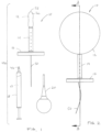
Fig. 1 is a side elevation of a system including an agent delivery device in a non-expanded configuration, an agent, and an inflation device. -
Fig. 2 is a side elevation of the agent delivery device in an expanded configuration. -
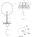
Fig. 3 is a longitudinal section view across line 3-3 inFig. 2 of the agent delivery device in the expanded configuration. -
Fig. 4 is an enlarged section view of a proximal portion of the agent delivery device. -
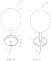
Fig. 5 is a bottom perspective view of the agent delivery device in the expanded configuration. -
Fig. 6 is a top perspective view of the agent delivery device in the expanded configuration. -
Fig. 7 is an exploded view of the agent delivery device in the expanded configuration. -
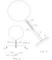
Fig. 8 is an exploded view of a second example of the agent delivery device in the expanded configuration. -
Fig. 9 is a longitudinal section view of the inflation member of the device inFig. 8 . -
Fig. 10 is a section view across line 10-10 inFig. 9 . -
Fig. 11 is an exploded view of a third example of the agent delivery device in the expanded configuration. -
Fig. 12 is a longitudinal section view of the inflation member of the device inFig. 11 . -
Fig. 13 is a section view across line 13-13 inFig. 12 . -
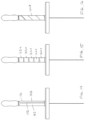
Fig. 14 is a side elevation of an agent delivery device in a collapsed configuration with the agent loaded in strips extending in a first direction about an exterior surface of the device. -
Fig. 15 is a side elevation of an agent delivery device in a collapsed configuration with the agent loaded in strips extending in a second direction about an exterior surface of the device. -
Fig. 16 is a side elevation of an agent delivery device in a collapsed configuration with the agent loaded in strips extending in a third direction about an exterior surface of the device. -
Fig. 17 is a top perspective view of another example of an anchor member of an agent delivery device in a collapsed configuration. -
Fig. 18 is a top perspective view of the anchor member ofFig. 17 in an expanded configuration. -
Fig. 19 is a top perspective view of another example of an anchor member of an agent delivery device in a collapsed configuration. -
Fig. 20 is a top perspective view of the anchor member ofFig. 19 in an expanded configuration. -
Fig. 21 is a side elevation of an embodiment of an agent delivery device according to the claimed invention. -
Fig. 22 is a longitudinal section view of the device ofFig. 21 across line 22-22. -
Fig. 23 is a side elevation of another embodiment of an agent delivery device according to the claimed invention. -
Fig. 24 is a longitudinal section view of the device ofFig. 23 across line 24-24. -
Fig. 25 is an assembly view of another example of an agent delivery device. - Fig. 26 is a bottom perspective view of another example of an agent delivery device.
- Embodiments forming part of the claimed invention are shown in
Figs. 21 to 24 . The examples shown inFigs. 1 to 20 ,25 and 26 do not form part of the claimed invention but are retained as they provide background to the claimed invention. Turning now toFigs. 1 through 4 , adevice 10 for delivery of a flowable agent to the anal and perianal tissues of a patient is provided. Thedelivery device 10 includes a deployableinternal anchor 12 adapted to comfortably anchor the device in the anal canal, ashaft 14 adapted to store and release the agent to the anal canal, and anexternal bumper 16 adapted to store and release the agent to the perianal tissue and externally anchor the device. Thedevice 10 optionally may be in a system 10a provided with a quantity of the agent 17 in a suitable form, such as a syringe 18, and an anchor expander, such as afluid bulb 20. - In an example of the
delivery device 10, theinternal anchor 12 is an inflatable balloon. Theballoon 12 includes aproximally extending stem 22, and avalve 24 that opens into the stem, described further below. Theballoon 12 may be compliant or non-compliant, and is preferably adapted to automatically collapse when empty of an inflation medium, and expand to a suitable size that operates to retain the device in the anal canal when inflated. The balloon may be made of a biodegradable material. Exemplar expanded sizes for theballoon 12 to anchor the device is 3 to 6 cm; other sizes may also be implemented. The inflation medium can be a liquid or gas. By way of example only, the inflation medium can be saline solution or air. When collapsed, a distal end 26 of the internal anchor presents a smooth, rounded, andatraumatic insertion tip 28. When expanded, theballoon 12 is larger in diameter than theshaft 14. - Referring to
Figs. 3 and 4 , theshaft 14 is hollow, including anagent storage portion 30 and a system or means by which to release the agent into tissue contact. In one exemple, theshaft 14 has a length of 3.5 cm between its proximal and distal ends; i.e., between theinternal anchor 12 and thebumper 16, and defines a longitudinal axis along such length and a diameter transverse to its longitudinal axis. As shown inFigs. 3 and 4 , the storage portion is areservoir 30 defined by a soft,porous membrane 32 surrounding thestem 22 and defining an outer surface of the reservoir. Themembrane 32 may be made from silicone or other porous materials. Thepores 34 of the porous membrane may be pre-filled or pre-covered with a heat-activatedmaterial 36, such as a gel, resin or wax, that melts wheninsertion tip 28 and theshaft 14 are inserted into the anal canal; i.e., at body temperature, to allow the flowable agent to be released from thereservoir 30 and out through thepores 34. - The
external bumper 16 is preferably oriented substantially orthogonal to the longitudinal axis of theshaft 14, and joins the shaft at the center of the bumper. Thebumper 16 may be circular or any other shape that prevents inward migration of the device into anus and preferably provides comfort to the patient. Thebumper 16 may have a same or different hardness and flexibility than the shaft. In one exemplar embodiment, thebumper 16 is 4 cm in diameter or other largest dimension (each of which is considered a 'diameter' for purposes herein). In an embodiment, thebumper 16 functions to supply and release agent at the external perianal tissue and also to prevent migration of thedevice 10 into the rectal vault. Similar to theshaft 14, thebumper 16 includes anagent storage portion 40 and a system to release the agent into contacting tissues. Thestorage portions porous membrane 32 defining the outer surface of both the bumper and the shaft, and use similar or dissimilar agent release systems. Aproximal end 42 of thebumper 16, enclosing itsstorage portion 40, includes aninjection port 42 for the injection of the agent into the reservoir. The injection port 44 is adapted to snugly receive thetip 46 of the syringe 18 carrying the agent 17 to facilitate filling thestorage portions bumper 16 may be constructed to have no storage portion; or even when provided with astorage portion 40, provided with no agent therein or thereon. - Referring to
Fig. 7 , an exemple assembly of theballoon 12 with stem 22 (assembled as one piece) is shown relative to theshaft 14 and bumper 16 (a unitary piece). The common reservoir of thestorage portions stem 22 and within the shaft 14 (reservoir 30) and around thestem 22 and within the bumper 16 (reservoir 40). - Alternatively, the
storage portions Figs. 8 through 10 , the stem 22a is provided with two longitudinal spines 23a that once inserted into and assembled relative to shaft and bumper operate to define two reservoirs about the stem. By way of another example, referring toFigs. 11 through 13 , the stem 22b is provided with four spines 23b that once inserted into and assembled relative to shaft and bumper operate to define four reservoirs about the stem. - Turning back to
Figs. 1 through 4 , theproximal valve 24, preferably accessed through an opening 48 in theproximal end 42 of thebumper 16, is adapted to permit injection of an inflation medium for expansion of the balloon. For that purpose, the tip of theinflation bulb 20 and the opening 48 are adapted and configured to be snugly fit together so that the inflation medium is effectively transferred under pressure from theinflation bulb 20, through thevalve 24 and into theballoon 12. - A
tether 50 extends from thevalve 24 and out of the proximal end of the device. Thetether 50 is attached to a leaflet of thevalve 24 and operates to open the valve to release the inflation member from the balloon. Thetether 50 also operates as a security device for the removal of the device from the patient. Referring to Fig. 26, as an alternative to tether 50, adeflectable tab 950 may be integrated with bumper 16'. When thefree end 952 of thetab 950 is pressed, thetab 950 includes internal structure (not shown) that interacts with the valve 24 (not shown) to open the valve; e.g., by deforming one of the valve leaflets. Thefree end 952 of thetab 950 may include raisedridges 954 so that it can be readily identified by user's touch when the device is inserted into the anus and not viewable. - Variations to the above described system are anticipated. Instead of filling the pores prior to implant,
porous membrane 32 may be covered with an impermeable sheet 60 that is removed after thestorage portion - In another example, the reservoir is filled after the device is inserted into the anal canal and the medicine is permitted to release immediately. In such case, no filler or cover is provided for the porous membrane.
- Turning now to
Fig. 15 , in another example, the storage portion is defined by anexternal surface area 158 of theshaft 116 and the agent is applied to the external surface of the shaft. The agent may be loaded instrips 162 that can be attached to the external surface to the shaft and tissue-contacting surface of the bumper prior to insertion of the device. The strips may include a diffusible form of the agent, similar to a transdermal patch. Thestrips 162 may include adhesive backing 164 for such application. Thestrips 162 may be provided separately from the device, and applied by the patient to the device prior to insertion, or the strips may be pre-attached to the device. Thestrips 162 may be loaded with one or more therapeutic agents, or strips with different agents can be separately supplied. Thestrips 162 can be applied longitudinally (Fig.14 ), applied circumferentially (strips 162a inFig. 15 ), or applied in a helical arrangement (strips 162b inFig. 16 ). - Referring now to
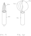
Figs. 17 and 18 , another example of adeployable anchor 212 for the device is shown. Thedeployable anchor 212 includes a plurality ofresilient retainers 270 that are stored or positioned in theshaft 214 during insertion of the device into the anal canal, and then deployed out of the shaft into an expanded state upon full insertion. Theretainers 270 may be a silicone, a non-irritating polymer, a spring metal, or a heat-activated shape memory. The deployment may be effected by user-applied force to longitudinally displace a spring-release hinge 272 of the retainer beyond the distal end of theshaft 214, heat-activation, or other means. Then, when it is necessary to remove the device, an opposing force is applied to collapse the retainers back into the shaft. - Turning now to
Figs. 19 and 20 , yet another exemple of a deployable anchor for the device is shown. The anchor includes a self-expandingbasket 312 that is stored in theshaft 314 and when advanced distally out of the shaft expands into a larger diameter anchoring configuration (Fig. 20 ). The basket may be optionally covered with asheet material 374, such that it operates as a self-expanding balloon. The basket may be made from resilient plastic or a superelastic metal alloy. - In the examples shown in
Figs. 17 through 20 , the device does not require an inflation valve. - Referring now to
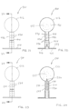
Figs. 21 and 22 , an embodiment forming part of the claimed invention, substantially similar to the device shown inFigs. 1 through 4 , is shown. Thedevice 410 includes aninflatable anchor 412, ashaft 414, and abumper 416. Theshaft 412 includes an interioragent storage volume 430 open to communicate with a primaryagent storage volume 431 within theanchor 412. Thebumper 416 includes an additional storage volume 433 in fluid communication with theagent storage volume 430. A one-way valve 424 is provided into theinterior volume 430 of theshaft 414, preferably at or adjacent thebumper 416. Anouter wall 432 of theshaft 414 includes a plurality of pores 434, and a tissue-contacting surface of the bumper also includespores 439. Thepores 434, 439 are filled with a meltable, dissolvable, bioabsorable or other releasable material 436 that temporarily prevents release of agent from withinstorage volumes device 410. In use, thedevice 410 is inserted into the anus, and aflowable agent 437 is injected through theshaft 414 and into theballoon anchor 412 to sufficiently inflate theanchor 412 to retain the device in the anus. Then, at a determined rate, the filler material 436 in the pores 434 of theouter wall 432 melts, dissolves or is otherwise removed in situ to permit theagent 437 to be dispensed from the pores over a short period of time. Different types of filler materials 436 may be used in different holes of the device in order to open select pores at different rates and times. The pores 434 are sufficiently small that even when opened, a measured flow rate of agent from inside the device to outside the device and into the anus is provided. The release rate is controlled by the size of the opening of the pore 434, the rate of melting, absorption, or dissolution of the filler material 436, the viscosity of theagent 437, and the contractile force of theballoon anchor 412 on theagent 437, as contraction of the anchor forces theagent 437 through the pores 434. Once thestorage portion 431 of theanchor 412 is depleted of agent 435 and collapsed inward, thedevice 410 is automatically releasable from the anus. - Turning now to
Figs. 23 and 24 , another embodiment according to the claimed invention of a device 510 substantially similar to the embodiment shown inFigs. 21 and 22 is provided. The device 510 is distinguished fromdevice 410 in that the shaft 514 includes an innertubular wall 533 within itsouter wall 532, and thevalve 524 is provided at or adjacent the boundary between the shaft 514 and the anchor 512. The device 510 is filled with agent 537 in a manner similar todevice 410, with the agent 537 stored in the storage volume 531 of the anchor 512, as well as the ring-shaped space 530 (in cross-sectional shape) defined between the inner and outertubular walls outer wall 532 melts, dissolves, or is otherwise released, the contractile force of the expanded anchor 512 forces the agent into thetoroidal space 530 and out of thepores 534 at a designed rate. Once the anchor 512 is depleted of agent 537 and collapsed, the device 510 is automatically releasable from the anus. - Referring now to
Fig. 25 , another example of adevice 610 for releasing an agent into the anal and perianal region is shown. Thedevice 610 includes a deformable silastic plug 612 and acore element 650. The plug 612 forms ashaft 614 and abumper 616. Theshaft 614 has anouter surface 630 provided with a coating or otherreleasable layer 637 of an agent. The plug 612 includes aninner bore 640 having a distal firstcylindrical portion 642, an ovoid second portion 644 having one end communicating with the first portion, a third cylindrical portion 646 extending from an opposite end of the second portion, and a proximal frustoconical fourth portion 648 extending from the third portion and having its largest diameter opening at the bumper. Thecore element 650 is provided for insertion into theinner bore 640. Thecore element 650 includes abulbous portion 652 adapted to be inserted within the ovoid portion 644 of the inner bore, a distal firstcylindrical tip 654 adapted to enter the firstcylindrical portion 642, and a proximal second cylindrical portion 656 adapted to reside within the third and fourth portions 646, 648 of the bore. Thebulbous portion 652 is preferably larger in diameter than the ovoid portion 644 of the bore such that it is adapted to deformably expand the plug 612 when thecore element 650 is inserted into theinner bore 640. In use, the plug 612 withagent 637 thereon is inserted into the anus; then thecore element 650 is inserted into theinner bore 640 to enlarge the diameter of the plug 612 and provide retention. The retained plug 612 is placed in the anus until the agent is 637 released from thesurface 630 of the plug 612. A tether 660 is preferably coupled to a proximal end of the core element to aid in removal of the core element and subsequent release of the plug. Alternatively, a bumper (as shown with respect to the plug) may be integrated with the core element to aid in its removal. Thecore element 650 optionally includeslumen 662 to vent gas while the device is in use. - It is anticipated that the device will be used to treat anal fissures and/or hemorrhoids. For such treatment, the agent can include one or more of a pain relief agent, an anti-inflammatory agent, and a muscle relaxant. It is further anticipated that the device can be used to deliver drugs systemically, particularly where a patient's condition indicates that the anal mucosa and underlying vasculature may be a suitable pathway for delivery of the agent. By way of example, such agents may include pain relivers, fever reducers, and anesthetics. Additionally, any agent currently delivered via suppositories can be delivered by the device described herein. Moreover, natural substances and nutrients in refined and unrefined forms (e.g., herbal tinctures, extracts, solutions, oils, and foods) can be used to treat conditions of the anus and rectum, as well as systemic conditions or needs via trans-anal and rectal absorption. By way of example only, aloe vera gel and cannabinoid oils can be delivered. By way of further example, it is anticipated that the device also can be used to deliver systemic therapeutic and non-therapeutic agents, including natural substances, nutrients, foods, and medications, to patients that are unconscious, such as those that are in a coma, or otherwise unsuitable for oral and/or intravenous administration. In one method of delivering a systemic agent to an unconscious patient, a device for delivery of an agent to anal and/or perianal tissues of the patient is provided with the agent and inserted into the anus of the patient. The agent may be provided loaded into or on the device or in a separate container that can be used to fill the device pre- or post-insertion into the anus. A portion of the device is expanded to anchor the device until a dose of the agent has been delivered to the anal and/or perianal tissues. Then the device is removed from the anus of the patient.
- There have been described and illustrated herein several embodiments of an agent delivery device for use in the anal canal and methods of treatment. While particular embodiments of the invention have been described, the scope of the invention is defined by the appended claims. Thus, it is intended that the disclosure include various therapeutic, non-therapeutic or combinations of agents, and different types of anchors, where appropriate. In addition, it is intended that each of the embodiments is also provided with in a dedicated suitable kit form. Further, it is intended that all of the embodiment be provided in any suitable sizes and shapes appropriate to treatment for various adult, child and other mammalian populations. It will therefore be appreciated by those skilled in the art that yet other modifications could be made to the provided invention without deviating from its scope.
Claims (12)
- A device (410; 510) for delivery of a flowable agent to anal and perianal tissue, comprising:a) an elastic anchor (412; 512) having a first interior (431; 531) adapted to be filled with the flowable agent, the anchor (412; 512) is configured to expand from a first configuration to an enlarged second configuration upon being filled with the agent (437; 537);b) a shaft (414; 514) having an outer porous wall (432; 532) at least partly defining a second interior (430; 530) adapted to receive the agent from the first interior (431; 531) of the anchor and release the agent to the anal tissue, the first interior (431; 531) of the anchor in fluid communication with the second interior (430; 530) of the shaft;c) an external bumper (416) that externally anchors the device to prevent uncontrolled inward migration of the device; andd) a one-way valve (424; 524) integrated with the device and through which to inject the agent (437; 537) into the first interior (431; 531) of the anchor, wherein when the anchor (412; 512) is expanded with the agent, a contractile force of the anchor (412; 512) urges the agent into the second interior (430; 530) of the shaft and out of the outer porous wall (432; 532);wherein the elastic anchor (412; 512) is configured to collapse to the first configuration upon depletion of the agent from the first interior (431; 531).
- The device (410; 510) according to claim 1, wherein:
the bumper (416) includes a third interior (433) in fluid communication with the second interior (430; 530), and wherein a tissue-contacting surface of the bumper (416) is porous (439) and is adapted to release the flowable agent (437; 537) from the third interior (433) to the perianal tissue. - The device (410; 510) according to claim 1, wherein:
The outer porous wall (432; 532) of the shaft includes a filler (436) that blocks the pores (434; 534), the filler (436) releasable out of the pores (434; 534) after the shaft (414; 514) is inserted into the anus. - The device (410; 510) according to claim 3, wherein:
the filler (436) is at least one of meltable, dissolvable, or bioabsorable. - The device (410; 510) according to claim 1, wherein:
the valve (424; 524) is located at or adjacent the bumper (416). - The device (410; 510) according to claim 1, wherein:
the valve (424; 524) is located at or adjacent the anchor (412; 512). - The device (410; 510) according to claim 1, wherein:
the shaft (514) includes an inner tubular wall (533), such that the second interior (530) has a ring-shaped cross-section. - The device (410; 510) according to claim 1, wherein:
the shaft (414; 514) and anchor (412; 512) are sized to be received within the anus, and once the anchor (412; 512) is in the second configuration retained within the anus. - The device (410; 510) according to claim 8, wherein:
the device is adapted to be automatically released from the anus when the flowable agent (437; 537) is depleted from the anchor (412; 512). - The device (410; 510) according to claim 1, wherein:
The outer porous wall of the shaft (432; 532) is adapted to release the agent (437; 537) to the anal tissue at a determined rate. - The device (410; 510) according to claim 1, in combination with a quantity of agent (437; 537) in deliverable form to the device for application to the anal and perianal tissues.
- The device (410; 510) according to claim 11, wherein the deliverable form is a flowable agent loaded in a syringe for injection into an interior of the device.
Applications Claiming Priority (2)
| Application Number | Priority Date | Filing Date | Title |
|---|---|---|---|
| US201862628589P | 2018-02-09 | 2018-02-09 | |
| PCT/US2019/016795 WO2019157022A1 (en) | 2018-02-09 | 2019-02-06 | Anal and perianal therapeutic substance delivery device |
Publications (4)
| Publication Number | Publication Date |
|---|---|
| EP3749404A1 EP3749404A1 (en) | 2020-12-16 |
| EP3749404A4 EP3749404A4 (en) | 2021-10-27 |
| EP3749404C0 EP3749404C0 (en) | 2023-07-19 |
| EP3749404B1 true EP3749404B1 (en) | 2023-07-19 |
Family
ID=67542174
Family Applications (1)
| Application Number | Title | Priority Date | Filing Date |
|---|---|---|---|
| EP19750998.7A Active EP3749404B1 (en) | 2018-02-09 | 2019-02-06 | Anal and perianal therapeutic substance delivery device |
Country Status (5)
| Country | Link |
|---|---|
| US (2) | US10987498B2 (en) |
| EP (1) | EP3749404B1 (en) |
| CA (1) | CA3089641A1 (en) |
| ES (1) | ES2956814T3 (en) |
| WO (1) | WO2019157022A1 (en) |
Families Citing this family (1)
| Publication number | Priority date | Publication date | Assignee | Title |
|---|---|---|---|---|
| CN108135736B (en) * | 2015-07-31 | 2021-05-18 | 新加坡科技研究局 | Device for insertion into a body cavity and method for producing the same |
Family Cites Families (41)
| Publication number | Priority date | Publication date | Assignee | Title |
|---|---|---|---|---|
| US1537992A (en) | 1925-05-19 | Medicatob | ||
| US2333342A (en) | 1942-05-18 | 1943-11-02 | Leith H Slocumb | Suppository |
| US3459175A (en) * | 1966-04-08 | 1969-08-05 | Roscoe E Miller | Medical device for control of enemata |
| US3760804A (en) | 1971-01-13 | 1973-09-25 | Alza Corp | Improved osmotic dispenser employing magnesium sulphate and magnesium chloride |
| US3777755A (en) | 1972-03-27 | 1973-12-11 | H Groves | Suppository |
| US3929132A (en) | 1973-04-10 | 1975-12-30 | Alza Corp | Osmotic dispenser |
| US3939842A (en) | 1974-09-05 | 1976-02-24 | Key Pharmaceuticals, Inc. | Hemorrhoidal device |
| EP0137774B1 (en) | 1984-11-01 | 1988-09-28 | Health Products Research, Inc. | Rectal insert |
| US5085650A (en) | 1989-10-20 | 1992-02-04 | Giglio Frank A | Gynecological urethral suppository |
| US5192266A (en) | 1992-02-18 | 1993-03-09 | Wilk Peter J | Device and related method for reducing swelling of hemorrhoidal tissues |
| US5263926A (en) | 1992-02-18 | 1993-11-23 | Wilk Peter J | Device and related method for reducing swelling of hemorrhoidal tissues |
| US5419763B1 (en) | 1994-01-04 | 1997-07-15 | Cor Trak Medical Inc | Prostatic drug-delivery catheter |
| US5637113A (en) * | 1994-12-13 | 1997-06-10 | Advanced Cardiovascular Systems, Inc. | Polymer film for wrapping a stent structure |
| US6364852B1 (en) | 2000-08-17 | 2002-04-02 | Sin Hang Lee | Device for reduction of the anal cushions in the treatment of minor hemorrhoidal disease |
| US7465295B2 (en) | 2000-10-20 | 2008-12-16 | Bergeron Michel G | Applicator for the delivery of topical formulations into mucosal cavities |
| US20020082679A1 (en) * | 2000-12-22 | 2002-06-27 | Avantec Vascular Corporation | Delivery or therapeutic capable agents |
| JP4025648B2 (en) | 2001-01-23 | 2007-12-26 | アビームーア メディカル インコーポレイテッド | Device used in the urethra |
| DE10205631C1 (en) * | 2002-02-12 | 2003-09-25 | Laubscher Max | Medical instrument with a tampon-like section |
| DE10305553B4 (en) | 2003-02-10 | 2005-11-03 | Lothar Dr.med. Göbel | Device for tamponade of body cavities |
| EP1666024A4 (en) | 2003-08-29 | 2009-11-25 | Sato Pharma | Preparation for rectal administration |
| US20050059992A1 (en) | 2003-09-17 | 2005-03-17 | Leiboff Arnold R. | Air introduction device for anastomotic leak testing |
| MX2007003666A (en) | 2004-09-27 | 2007-05-24 | Medical Instill Tech Inc | Laterally-actuated dispenser with one- way valve for storing and dispensing metered amounts of substances. |
| JP2007014475A (en) | 2005-07-06 | 2007-01-25 | Fujinon Corp | Balloon control device for endoscope apparatus |
| US8123760B2 (en) | 2005-08-05 | 2012-02-28 | Plexus Biomedical, Inc. | Method, apparatus and system for preventing or reducing the severity of hemorrhoids |
| EP1971390B1 (en) | 2005-12-30 | 2017-12-13 | RDD Pharma Ltd. | Device for treating the anal sphincter |
| US8500771B2 (en) * | 2007-01-16 | 2013-08-06 | Radiadyne, Llc | Rectal balloon apparatus with pressure relieving lumen and sensors |
| JP2010526635A (en) * | 2007-05-14 | 2010-08-05 | バイオプロテクト リミテッド | Delivery device for delivering biologically active agents to internal tissues of the body |
| US8887731B2 (en) | 2008-02-27 | 2014-11-18 | Ralph Zipper | Pessary device |
| WO2013116670A1 (en) | 2012-02-01 | 2013-08-08 | Hospi Corporation | Valved enteral administration assembly |
| CN201353368Y (en) | 2008-12-23 | 2009-12-02 | 夏兰云 | Recta drug delivery device |
| EP2445481B1 (en) | 2009-06-18 | 2017-03-22 | Rdd Pharma Ltd. | Methods and devices for delivery of pharmaceutical agents within orifices of the body |
| US8500684B2 (en) * | 2009-09-18 | 2013-08-06 | Bruce A. Gardner | Balloon catheter |
| TWI643623B (en) | 2011-10-03 | 2018-12-11 | 菲瑞茵公司 | Composition for the treatment of fistula |
| ITCO20120004A1 (en) | 2012-02-07 | 2013-08-08 | Giuseppe Caccia | APPARATUS FOR VAGINAL AND ANAL DYNAMIC ELECTROPORATION |
| US9005108B2 (en) | 2012-09-27 | 2015-04-14 | Palo Alto Research Center Incorporated | Multiple reservoir drug delivery device and methods |
| US20140155846A1 (en) | 2012-11-30 | 2014-06-05 | Sebastian Jack Choularton | Flatus Transporter |
| US9889280B2 (en) | 2013-04-01 | 2018-02-13 | Indiana University Research And Technology Corporation | Rectal catheter configured for pediatric care |
| GB2519055A (en) | 2013-08-01 | 2015-04-15 | Calla Lily Personal Care Ltd | Drug delivery device |
| US20150126968A1 (en) | 2013-11-05 | 2015-05-07 | Palo Alto Research Center Incorporated | Fluid delivery devices and methods |
| DE102014119576A1 (en) | 2014-12-23 | 2016-06-23 | Ernst-Moritz-Arndt-Universität Greifswald | Pharmaceutical form for administration to mucous membranes |
| EP3103500A1 (en) * | 2015-06-11 | 2016-12-14 | Lohmann & Rauscher GmbH | Balloon catheter with open pores |
-
2019
- 2019-02-06 EP EP19750998.7A patent/EP3749404B1/en active Active
- 2019-02-06 ES ES19750998T patent/ES2956814T3/en active Active
- 2019-02-06 CA CA3089641A patent/CA3089641A1/en active Pending
- 2019-02-06 WO PCT/US2019/016795 patent/WO2019157022A1/en unknown
- 2019-02-08 US US16/270,708 patent/US10987498B2/en active Active
-
2021
- 2021-04-06 US US17/223,967 patent/US20210220629A1/en active Pending
Also Published As
| Publication number | Publication date |
|---|---|
| EP3749404C0 (en) | 2023-07-19 |
| US10987498B2 (en) | 2021-04-27 |
| US20190247632A1 (en) | 2019-08-15 |
| EP3749404A1 (en) | 2020-12-16 |
| WO2019157022A1 (en) | 2019-08-15 |
| EP3749404A4 (en) | 2021-10-27 |
| US20210220629A1 (en) | 2021-07-22 |
| CA3089641A1 (en) | 2019-08-15 |
| ES2956814T3 (en) | 2023-12-28 |
Similar Documents
| Publication | Publication Date | Title |
|---|---|---|
| ES2225991T3 (en) | IRRIGATION DEVICE. | |
| EP0980280B1 (en) | Drug delivery and gene therapy delivery system | |
| US5628784A (en) | Endoprosthesis that can be percutaneously implanted in the body of a patient | |
| US3817248A (en) | Self powered device for delivering beneficial agent | |
| US4286596A (en) | Tampon containing a liquid medicant | |
| US7691079B2 (en) | Device for tamponade of body cavities and mechanical anchoring of a catheter | |
| KR20010032290A (en) | Expandable body device for the gastric cavity and method | |
| US20080086101A1 (en) | Ophthalmic insert | |
| US20210220629A1 (en) | Methods for using anal and perianal therapeutic substance delivery device | |
| US5817124A (en) | Anal dilator with self-expanding element | |
| WO2014129552A1 (en) | Means for controlled release of fluid, and endoscope and endoscopic surgical instrument comprising same | |
| KR101837303B1 (en) | urine drainage catheter | |
| CN116113447A (en) | Device for treating bleeding in body cavities or spaces including epistaxis and methods of making and using the same | |
| CN108135736B (en) | Device for insertion into a body cavity and method for producing the same | |
| EP4199991B1 (en) | A self-retaining enema nozzle and an enema system comprising said enema nozzle | |
| EP3756720A2 (en) | Implantable device for delivering fluid to internal target | |
| JPH10502269A (en) | Urinary incontinence prevention device and incontinence prevention law | |
| WO2023156322A1 (en) | An enema nozzle comprising retention means, and an enema system comprising said enema nozzle | |
| US10226607B1 (en) | Daneshvar special medication pads, suppositories and methods |
Legal Events
| Date | Code | Title | Description |
|---|---|---|---|
| STAA | Information on the status of an ep patent application or granted ep patent |
Free format text: STATUS: THE INTERNATIONAL PUBLICATION HAS BEEN MADE |
|
| PUAI | Public reference made under article 153(3) epc to a published international application that has entered the european phase |
Free format text: ORIGINAL CODE: 0009012 |
|
| STAA | Information on the status of an ep patent application or granted ep patent |
Free format text: STATUS: REQUEST FOR EXAMINATION WAS MADE |
|
| 17P | Request for examination filed |
Effective date: 20200827 |
|
| AK | Designated contracting states |
Kind code of ref document: A1 Designated state(s): AL AT BE BG CH CY CZ DE DK EE ES FI FR GB GR HR HU IE IS IT LI LT LU LV MC MK MT NL NO PL PT RO RS SE SI SK SM TR |
|
| AX | Request for extension of the european patent |
Extension state: BA ME |
|
| DAV | Request for validation of the european patent (deleted) | ||
| DAX | Request for extension of the european patent (deleted) | ||
| A4 | Supplementary search report drawn up and despatched |
Effective date: 20210928 |
|
| RIC1 | Information provided on ipc code assigned before grant |
Ipc: A61M 31/00 20060101ALI20210922BHEP Ipc: A61M 25/10 20130101ALI20210922BHEP Ipc: A61M 25/00 20060101AFI20210922BHEP |
|
| GRAP | Despatch of communication of intention to grant a patent |
Free format text: ORIGINAL CODE: EPIDOSNIGR1 |
|
| STAA | Information on the status of an ep patent application or granted ep patent |
Free format text: STATUS: GRANT OF PATENT IS INTENDED |
|
| INTG | Intention to grant announced |
Effective date: 20230224 |
|
| GRAS | Grant fee paid |
Free format text: ORIGINAL CODE: EPIDOSNIGR3 |
|
| GRAA | (expected) grant |
Free format text: ORIGINAL CODE: 0009210 |
|
| STAA | Information on the status of an ep patent application or granted ep patent |
Free format text: STATUS: THE PATENT HAS BEEN GRANTED |
|
| AK | Designated contracting states |
Kind code of ref document: B1 Designated state(s): AL AT BE BG CH CY CZ DE DK EE ES FI FR GB GR HR HU IE IS IT LI LT LU LV MC MK MT NL NO PL PT RO RS SE SI SK SM TR |
|
| REG | Reference to a national code |
Ref country code: GB Ref legal event code: FG4D |
|
| REG | Reference to a national code |
Ref country code: CH Ref legal event code: EP |
|
| REG | Reference to a national code |
Ref country code: DE Ref legal event code: R096 Ref document number: 602019033079 Country of ref document: DE |
|
| REG | Reference to a national code |
Ref country code: IE Ref legal event code: FG4D |
|
| U01 | Request for unitary effect filed |
Effective date: 20230725 |
|
| U07 | Unitary effect registered |
Designated state(s): AT BE BG DE DK EE FI FR IT LT LU LV MT NL PT SE SI Effective date: 20230731 |
|
| REG | Reference to a national code |
Ref country code: LT Ref legal event code: MG9D |
|
| REG | Reference to a national code |
Ref country code: ES Ref legal event code: FG2A Ref document number: 2956814 Country of ref document: ES Kind code of ref document: T3 Effective date: 20231228 |
|
| PG25 | Lapsed in a contracting state [announced via postgrant information from national office to epo] |
Ref country code: GR Free format text: LAPSE BECAUSE OF FAILURE TO SUBMIT A TRANSLATION OF THE DESCRIPTION OR TO PAY THE FEE WITHIN THE PRESCRIBED TIME-LIMIT Effective date: 20231020 |
|
| PG25 | Lapsed in a contracting state [announced via postgrant information from national office to epo] |
Ref country code: IS Free format text: LAPSE BECAUSE OF FAILURE TO SUBMIT A TRANSLATION OF THE DESCRIPTION OR TO PAY THE FEE WITHIN THE PRESCRIBED TIME-LIMIT Effective date: 20231119 |
|
| PG25 | Lapsed in a contracting state [announced via postgrant information from national office to epo] |
Ref country code: RS Free format text: LAPSE BECAUSE OF FAILURE TO SUBMIT A TRANSLATION OF THE DESCRIPTION OR TO PAY THE FEE WITHIN THE PRESCRIBED TIME-LIMIT Effective date: 20230719 Ref country code: NO Free format text: LAPSE BECAUSE OF FAILURE TO SUBMIT A TRANSLATION OF THE DESCRIPTION OR TO PAY THE FEE WITHIN THE PRESCRIBED TIME-LIMIT Effective date: 20231019 Ref country code: IS Free format text: LAPSE BECAUSE OF FAILURE TO SUBMIT A TRANSLATION OF THE DESCRIPTION OR TO PAY THE FEE WITHIN THE PRESCRIBED TIME-LIMIT Effective date: 20231119 Ref country code: HR Free format text: LAPSE BECAUSE OF FAILURE TO SUBMIT A TRANSLATION OF THE DESCRIPTION OR TO PAY THE FEE WITHIN THE PRESCRIBED TIME-LIMIT Effective date: 20230719 Ref country code: GR Free format text: LAPSE BECAUSE OF FAILURE TO SUBMIT A TRANSLATION OF THE DESCRIPTION OR TO PAY THE FEE WITHIN THE PRESCRIBED TIME-LIMIT Effective date: 20231020 |
|
| PG25 | Lapsed in a contracting state [announced via postgrant information from national office to epo] |
Ref country code: PL Free format text: LAPSE BECAUSE OF FAILURE TO SUBMIT A TRANSLATION OF THE DESCRIPTION OR TO PAY THE FEE WITHIN THE PRESCRIBED TIME-LIMIT Effective date: 20230719 |
|
| U20 | Renewal fee paid [unitary effect] |
Year of fee payment: 6 Effective date: 20240223 |
|
| PGFP | Annual fee paid to national office [announced via postgrant information from national office to epo] |
Ref country code: ES Payment date: 20240305 Year of fee payment: 6 |