EP3749402B1 - Ventilator arrangement - Google Patents
Ventilator arrangement Download PDFInfo
- Publication number
- EP3749402B1 EP3749402B1 EP19705404.2A EP19705404A EP3749402B1 EP 3749402 B1 EP3749402 B1 EP 3749402B1 EP 19705404 A EP19705404 A EP 19705404A EP 3749402 B1 EP3749402 B1 EP 3749402B1
- Authority
- EP
- European Patent Office
- Prior art keywords
- subject
- ventilation
- ventilator arrangement
- manoeuvre
- external
- Prior art date
- Legal status (The legal status is an assumption and is not a legal conclusion. Google has not performed a legal analysis and makes no representation as to the accuracy of the status listed.)
- Active
Links
- 238000009423 ventilation Methods 0.000 claims description 165
- 210000004072 lung Anatomy 0.000 claims description 116
- 244000144985 peep Species 0.000 claims description 102
- 230000029058 respiratory gaseous exchange Effects 0.000 claims description 97
- 230000008859 change Effects 0.000 claims description 52
- 238000004590 computer program Methods 0.000 claims description 20
- 230000009471 action Effects 0.000 claims description 11
- 230000003247 decreasing effect Effects 0.000 claims description 5
- 238000000034 method Methods 0.000 description 121
- 239000007789 gas Substances 0.000 description 17
- 230000003434 inspiratory effect Effects 0.000 description 13
- 230000001276 controlling effect Effects 0.000 description 12
- 238000005259 measurement Methods 0.000 description 12
- 230000001105 regulatory effect Effects 0.000 description 11
- 210000001015 abdomen Anatomy 0.000 description 6
- 230000000630 rising effect Effects 0.000 description 6
- 230000000977 initiatory effect Effects 0.000 description 4
- 208000007123 Pulmonary Atelectasis Diseases 0.000 description 3
- 238000011084 recovery Methods 0.000 description 3
- 230000000241 respiratory effect Effects 0.000 description 3
- 230000006978 adaptation Effects 0.000 description 2
- 238000013461 design Methods 0.000 description 2
- 230000010354 integration Effects 0.000 description 2
- 238000002360 preparation method Methods 0.000 description 2
- 238000003825 pressing Methods 0.000 description 2
- 230000005236 sound signal Effects 0.000 description 2
- 239000003570 air Substances 0.000 description 1
- 239000012080 ambient air Substances 0.000 description 1
- 230000006399 behavior Effects 0.000 description 1
- 230000031018 biological processes and functions Effects 0.000 description 1
- 230000004397 blinking Effects 0.000 description 1
- 230000007423 decrease Effects 0.000 description 1
- 230000001419 dependent effect Effects 0.000 description 1
- 230000000694 effects Effects 0.000 description 1
- 230000006870 function Effects 0.000 description 1
- 230000001435 haemodynamic effect Effects 0.000 description 1
- 230000036541 health Effects 0.000 description 1
- 238000002357 laparoscopic surgery Methods 0.000 description 1
- 238000012544 monitoring process Methods 0.000 description 1
- 230000007115 recruitment Effects 0.000 description 1
- 210000002345 respiratory system Anatomy 0.000 description 1
- 230000004044 response Effects 0.000 description 1
- 230000002000 scavenging effect Effects 0.000 description 1
- 239000000126 substance Substances 0.000 description 1
- 238000001356 surgical procedure Methods 0.000 description 1
- 230000009897 systematic effect Effects 0.000 description 1
- 210000000115 thoracic cavity Anatomy 0.000 description 1
- 210000003437 trachea Anatomy 0.000 description 1
- 238000012546 transfer Methods 0.000 description 1
- 230000000007 visual effect Effects 0.000 description 1
Images

Classifications
-
- A—HUMAN NECESSITIES
- A61—MEDICAL OR VETERINARY SCIENCE; HYGIENE
- A61M—DEVICES FOR INTRODUCING MEDIA INTO, OR ONTO, THE BODY; DEVICES FOR TRANSDUCING BODY MEDIA OR FOR TAKING MEDIA FROM THE BODY; DEVICES FOR PRODUCING OR ENDING SLEEP OR STUPOR
- A61M16/00—Devices for influencing the respiratory system of patients by gas treatment, e.g. mouth-to-mouth respiration; Tracheal tubes
- A61M16/021—Devices for influencing the respiratory system of patients by gas treatment, e.g. mouth-to-mouth respiration; Tracheal tubes operated by electrical means
- A61M16/022—Control means therefor
- A61M16/024—Control means therefor including calculation means, e.g. using a processor
-
- A—HUMAN NECESSITIES
- A61—MEDICAL OR VETERINARY SCIENCE; HYGIENE
- A61B—DIAGNOSIS; SURGERY; IDENTIFICATION
- A61B5/00—Measuring for diagnostic purposes; Identification of persons
- A61B5/08—Detecting, measuring or recording devices for evaluating the respiratory organs
- A61B5/091—Measuring volume of inspired or expired gases, e.g. to determine lung capacity
-
- A—HUMAN NECESSITIES
- A61—MEDICAL OR VETERINARY SCIENCE; HYGIENE
- A61M—DEVICES FOR INTRODUCING MEDIA INTO, OR ONTO, THE BODY; DEVICES FOR TRANSDUCING BODY MEDIA OR FOR TAKING MEDIA FROM THE BODY; DEVICES FOR PRODUCING OR ENDING SLEEP OR STUPOR
- A61M16/00—Devices for influencing the respiratory system of patients by gas treatment, e.g. mouth-to-mouth respiration; Tracheal tubes
- A61M16/10—Preparation of respiratory gases or vapours
- A61M16/12—Preparation of respiratory gases or vapours by mixing different gases
-
- A—HUMAN NECESSITIES
- A61—MEDICAL OR VETERINARY SCIENCE; HYGIENE
- A61M—DEVICES FOR INTRODUCING MEDIA INTO, OR ONTO, THE BODY; DEVICES FOR TRANSDUCING BODY MEDIA OR FOR TAKING MEDIA FROM THE BODY; DEVICES FOR PRODUCING OR ENDING SLEEP OR STUPOR
- A61M16/00—Devices for influencing the respiratory system of patients by gas treatment, e.g. mouth-to-mouth respiration; Tracheal tubes
- A61M16/20—Valves specially adapted to medical respiratory devices
- A61M16/201—Controlled valves
- A61M16/202—Controlled valves electrically actuated
- A61M16/203—Proportional
- A61M16/204—Proportional used for inhalation control
-
- A—HUMAN NECESSITIES
- A61—MEDICAL OR VETERINARY SCIENCE; HYGIENE
- A61M—DEVICES FOR INTRODUCING MEDIA INTO, OR ONTO, THE BODY; DEVICES FOR TRANSDUCING BODY MEDIA OR FOR TAKING MEDIA FROM THE BODY; DEVICES FOR PRODUCING OR ENDING SLEEP OR STUPOR
- A61M16/00—Devices for influencing the respiratory system of patients by gas treatment, e.g. mouth-to-mouth respiration; Tracheal tubes
- A61M16/20—Valves specially adapted to medical respiratory devices
- A61M16/201—Controlled valves
- A61M16/202—Controlled valves electrically actuated
- A61M16/203—Proportional
- A61M16/205—Proportional used for exhalation control
-
- A—HUMAN NECESSITIES
- A61—MEDICAL OR VETERINARY SCIENCE; HYGIENE
- A61M—DEVICES FOR INTRODUCING MEDIA INTO, OR ONTO, THE BODY; DEVICES FOR TRANSDUCING BODY MEDIA OR FOR TAKING MEDIA FROM THE BODY; DEVICES FOR PRODUCING OR ENDING SLEEP OR STUPOR
- A61M16/00—Devices for influencing the respiratory system of patients by gas treatment, e.g. mouth-to-mouth respiration; Tracheal tubes
- A61M16/0003—Accessories therefor, e.g. sensors, vibrators, negative pressure
- A61M2016/0027—Accessories therefor, e.g. sensors, vibrators, negative pressure pressure meter
-
- A—HUMAN NECESSITIES
- A61—MEDICAL OR VETERINARY SCIENCE; HYGIENE
- A61M—DEVICES FOR INTRODUCING MEDIA INTO, OR ONTO, THE BODY; DEVICES FOR TRANSDUCING BODY MEDIA OR FOR TAKING MEDIA FROM THE BODY; DEVICES FOR PRODUCING OR ENDING SLEEP OR STUPOR
- A61M16/00—Devices for influencing the respiratory system of patients by gas treatment, e.g. mouth-to-mouth respiration; Tracheal tubes
- A61M16/0003—Accessories therefor, e.g. sensors, vibrators, negative pressure
- A61M2016/003—Accessories therefor, e.g. sensors, vibrators, negative pressure with a flowmeter
- A61M2016/0033—Accessories therefor, e.g. sensors, vibrators, negative pressure with a flowmeter electrical
- A61M2016/0036—Accessories therefor, e.g. sensors, vibrators, negative pressure with a flowmeter electrical in the breathing tube and used in both inspiratory and expiratory phase
-
- A—HUMAN NECESSITIES
- A61—MEDICAL OR VETERINARY SCIENCE; HYGIENE
- A61M—DEVICES FOR INTRODUCING MEDIA INTO, OR ONTO, THE BODY; DEVICES FOR TRANSDUCING BODY MEDIA OR FOR TAKING MEDIA FROM THE BODY; DEVICES FOR PRODUCING OR ENDING SLEEP OR STUPOR
- A61M16/00—Devices for influencing the respiratory system of patients by gas treatment, e.g. mouth-to-mouth respiration; Tracheal tubes
- A61M16/0003—Accessories therefor, e.g. sensors, vibrators, negative pressure
- A61M2016/003—Accessories therefor, e.g. sensors, vibrators, negative pressure with a flowmeter
- A61M2016/0033—Accessories therefor, e.g. sensors, vibrators, negative pressure with a flowmeter electrical
- A61M2016/0039—Accessories therefor, e.g. sensors, vibrators, negative pressure with a flowmeter electrical in the inspiratory circuit
-
- A—HUMAN NECESSITIES
- A61—MEDICAL OR VETERINARY SCIENCE; HYGIENE
- A61M—DEVICES FOR INTRODUCING MEDIA INTO, OR ONTO, THE BODY; DEVICES FOR TRANSDUCING BODY MEDIA OR FOR TAKING MEDIA FROM THE BODY; DEVICES FOR PRODUCING OR ENDING SLEEP OR STUPOR
- A61M16/00—Devices for influencing the respiratory system of patients by gas treatment, e.g. mouth-to-mouth respiration; Tracheal tubes
- A61M16/0003—Accessories therefor, e.g. sensors, vibrators, negative pressure
- A61M2016/003—Accessories therefor, e.g. sensors, vibrators, negative pressure with a flowmeter
- A61M2016/0033—Accessories therefor, e.g. sensors, vibrators, negative pressure with a flowmeter electrical
- A61M2016/0042—Accessories therefor, e.g. sensors, vibrators, negative pressure with a flowmeter electrical in the expiratory circuit
-
- A—HUMAN NECESSITIES
- A61—MEDICAL OR VETERINARY SCIENCE; HYGIENE
- A61M—DEVICES FOR INTRODUCING MEDIA INTO, OR ONTO, THE BODY; DEVICES FOR TRANSDUCING BODY MEDIA OR FOR TAKING MEDIA FROM THE BODY; DEVICES FOR PRODUCING OR ENDING SLEEP OR STUPOR
- A61M2205/00—General characteristics of the apparatus
- A61M2205/15—Detection of leaks
-
- A—HUMAN NECESSITIES
- A61—MEDICAL OR VETERINARY SCIENCE; HYGIENE
- A61M—DEVICES FOR INTRODUCING MEDIA INTO, OR ONTO, THE BODY; DEVICES FOR TRANSDUCING BODY MEDIA OR FOR TAKING MEDIA FROM THE BODY; DEVICES FOR PRODUCING OR ENDING SLEEP OR STUPOR
- A61M2205/00—General characteristics of the apparatus
- A61M2205/50—General characteristics of the apparatus with microprocessors or computers
- A61M2205/502—User interfaces, e.g. screens or keyboards
- A61M2205/505—Touch-screens; Virtual keyboard or keypads; Virtual buttons; Soft keys; Mouse touches
-
- A—HUMAN NECESSITIES
- A61—MEDICAL OR VETERINARY SCIENCE; HYGIENE
- A61M—DEVICES FOR INTRODUCING MEDIA INTO, OR ONTO, THE BODY; DEVICES FOR TRANSDUCING BODY MEDIA OR FOR TAKING MEDIA FROM THE BODY; DEVICES FOR PRODUCING OR ENDING SLEEP OR STUPOR
- A61M2205/00—General characteristics of the apparatus
- A61M2205/50—General characteristics of the apparatus with microprocessors or computers
- A61M2205/52—General characteristics of the apparatus with microprocessors or computers with memories providing a history of measured variating parameters of apparatus or patient
-
- A—HUMAN NECESSITIES
- A61—MEDICAL OR VETERINARY SCIENCE; HYGIENE
- A61M—DEVICES FOR INTRODUCING MEDIA INTO, OR ONTO, THE BODY; DEVICES FOR TRANSDUCING BODY MEDIA OR FOR TAKING MEDIA FROM THE BODY; DEVICES FOR PRODUCING OR ENDING SLEEP OR STUPOR
- A61M2205/00—General characteristics of the apparatus
- A61M2205/58—Means for facilitating use, e.g. by people with impaired vision
- A61M2205/581—Means for facilitating use, e.g. by people with impaired vision by audible feedback
-
- A—HUMAN NECESSITIES
- A61—MEDICAL OR VETERINARY SCIENCE; HYGIENE
- A61M—DEVICES FOR INTRODUCING MEDIA INTO, OR ONTO, THE BODY; DEVICES FOR TRANSDUCING BODY MEDIA OR FOR TAKING MEDIA FROM THE BODY; DEVICES FOR PRODUCING OR ENDING SLEEP OR STUPOR
- A61M2205/00—General characteristics of the apparatus
- A61M2205/58—Means for facilitating use, e.g. by people with impaired vision
- A61M2205/582—Means for facilitating use, e.g. by people with impaired vision by tactile feedback
-
- A—HUMAN NECESSITIES
- A61—MEDICAL OR VETERINARY SCIENCE; HYGIENE
- A61M—DEVICES FOR INTRODUCING MEDIA INTO, OR ONTO, THE BODY; DEVICES FOR TRANSDUCING BODY MEDIA OR FOR TAKING MEDIA FROM THE BODY; DEVICES FOR PRODUCING OR ENDING SLEEP OR STUPOR
- A61M2205/00—General characteristics of the apparatus
- A61M2205/58—Means for facilitating use, e.g. by people with impaired vision
- A61M2205/583—Means for facilitating use, e.g. by people with impaired vision by visual feedback
-
- A—HUMAN NECESSITIES
- A61—MEDICAL OR VETERINARY SCIENCE; HYGIENE
- A61M—DEVICES FOR INTRODUCING MEDIA INTO, OR ONTO, THE BODY; DEVICES FOR TRANSDUCING BODY MEDIA OR FOR TAKING MEDIA FROM THE BODY; DEVICES FOR PRODUCING OR ENDING SLEEP OR STUPOR
- A61M2230/00—Measuring parameters of the user
- A61M2230/40—Respiratory characteristics
Definitions
- the present disclosure relates to a ventilator arrangement and to a computer program product.
- the ventilator arrangement might provide functionality to apply a set level for positive end-expiratory pressure, PEEP.
- PEEP positive end-expiratory pressure
- US2017/028145 A1 discloses a method of ventilating a patient.
- the method comprises measuring a patient physiological parameter while the patient is in a first position and recording the measured patient physiological parameter as a baseline.
- the method further comprises tilting the patient from the first position to a second position and measuring the patient physiological parameter when the patient is in the second position.
- the method further comprises performing an action based on a change in the measured physiological parameter from the baseline when the patient is in the second position.
- the action is at least one of modifying a ventilation parameter, generating an alert, and providing a recommendation.
- the ventilator arrangement applies a set positive end-expiratory pressure, PEEP, level for performing the ventilation.
- the method comprises the step of performing a ventilation pause in the ongoing ventilation of the subject prior to the external manoeuvre.
- the method further comprises the step of determining a possible change in airway pressure ( ⁇ Paw) of the subject during pausing of the ventilation.
- the method even further comprises the step of resuming the ventilation of the subject after at least parts of the external manoeuvre.
- an updated set level for the PEEP is applied.
- the updated set level basically corresponds to the sum of the set PEEP level prior to pausing the ventilation and the determined possible change in airway pressure ( ⁇ Paw) of the subject.
- the method takes care of potential changes in the pressure to which the lungs are exposed to.
- the EELV is thus maintained.
- the ventilator arrangement can take care of the adaption itself without the need from the personal to change set-values of the ventilator arrangement.
- an adaption of the PEEP-level can be provided without any delay. Thus complexity is reduced. Further, a situation is created which allows performing an external manoeuvre at the subject in a safer way.
- the pausing of the ventilation is initiated by a manual action on an input means of the ventilator arrangement. This allows the personal to reduce the amount of time for which the ventilation is paused, for example by initiation that part of the method only when the subject is ready for the external manoeuvre.
- the resumption of the ventilation starts at a first pre-determined time period after pausing the ventilation. This assures that the ventilation is not paused too long. This helps reducing or avoiding risks to the subject by pausing of the ventilation.
- the method further comprises the step of indicating the resumption of the ventilation a second pre-determined time period prior to resuming the ventilation. This can warn the personal that the external manoeuvre has to come to an end, or at least to a pause. This avoids or reduces the risks to the subject which might be caused by a pause in ventilation and/or the external manoeuvre itself.
- the resumption of the ventilation is initiated by a manual action on an input means of the ventilator arrangement. This allows giving the personal full control of the time when the ventilator arrangement resumes ventilation. Thus a high flexibility is achieved. Further, in case the external manoeuvre is performed faster than expected, the ventilation might be resumed earlier. Thus the pause in ventilation can be reduced to a minimum.
- the ventilation of the subject is paused during an expiration phase. This usually implies that the thoracic pressure is comparably smaller, which can give advantages from a haemodynamic point of view.
- the ventilation can be paused at the end of the expiration phase or at any other time during the expiration phase.
- the ventilation of the subject is paused during an inspiration phase. Since there is usually more air in the lungs during inspiration, especially at the end of an inspiration phase, the subject might tolerate a larger ventilation pause in a safer way.
- the ventilation can be paused at the end of the inspiration phase or at any other time during the inspiration phase.
- the external manoeuvre is divided in several sub-steps with pauses in between the sub-steps.
- the method is repeated for each sub-step of the external manoeuvre. This allows using the method even for external manoeuvres requiring a longer time period.
- the time period of the external manoeuvre might exceed the time period for which the ventilation of the subject safely can be paused
- the division into sub-steps, where each subject has a suitable time length, such as a time length not exceeding the time length for which the ventilation of the subject can be safely paused might allow still using the method although the comparably long manoeuvre.
- the method comprises the step of determining start conditions including at least breathing circuit leakage. This can provide a more accurate method.
- the start conditions also include determining a tidal volume, TV, of the subject. This might be a useful quantity for improving accuracy of the method.
- a ventilator arrangement for maintaining the end expiratory lung volume, EELV, of a subject when an external manoeuvre is performed on the subject ventilated by the ventilator arrangement.
- the ventilator arrangement is arranged to apply a set positive end-expiratory pressure, PEEP, level for performing the ventilation.
- the ventilator arrangement is further arranged to performing a ventilation pause in the ventilation of the subject prior to the external manoeuvre.
- the ventilator arrangement is even further arranged to determining a possible change in airway pressure ( ⁇ Paw) of the subject during pausing of the ventilation.
- the ventilator arrangement is yet even further arranged to resuming the ventilation of the subject after at least parts of the external manoeuvre.
- an updated set level for the PEEP is applied.
- the updated set level basically corresponds to the sum of the set PEEP level prior to pausing the ventilation and the determined possible change in airway pressure ( ⁇ Paw) of the subject.
- the ventilator arrangement is arranged to initiate the pause of the ventilation based on a manual action on an input means of the ventilator arrangement.
- the ventilator arrangement is arranged to resume the ventilation at a first pre-determined time period after pausing the ventilation.
- the ventilator arrangement is arranged to indicate the resumption of the ventilation a second pre-determined time period prior to resuming the ventilation.
- the ventilator arrangement is arranged to initiate the resumption of the ventilation based on a manual action on an input means of the ventilator arrangement.
- the ventilator arrangement is arranged to pause the ventilation of the subject during an expiration phase. In one embodiment, the ventilator arrangement is arranged to pause the ventilation of the subject at the end of an expiration phase.
- the ventilator arrangement is arranged to pause the ventilation of the subject during an inspiration phase. In one embodiment, the ventilator arrangement is arranged to pause the ventilation of the subject at the end of an inspiration phase.
- the ventilator arrangement is arranged to determine start conditions including at least breathing circuit leakage.
- the start conditions also include determining a tidal volume, TV, of the subject.
- a computer program product comprising instructions which, when the program is executed by a computer, cause the computer to carry out the method for controlling a ventilator arrangement for maintaining the end expiratory lung volume, EELV, of a subject according to the present disclosure.
- a computer-readable medium comprising instructions which, when executed by a computer, cause the computer to carry out the method for controlling a ventilator arrangement for maintaining the end expiratory lung volume, EELV, of a subject according to the present disclosure.
- a method for controlling a ventilator arrangement for achieving a desired end expiratory lung volume, EELV, when an external manoeuvre is performed on a subject ventilated by the ventilator arrangement applies a set positive end-expiratory pressure, PEEP, level for performing the ventilation.
- the method comprises the step of determining a difference between inspired and expired tidal lung volume of a breathing cycle of the subject.
- the method further comprises the step of adjusting the PEEP level after the breathing cycle of the subject based on the determined difference so that the desired EELV of the subject is achieved.
- the steps are repeated for several breathing cycles during and/or after the external manoeuvre.
- the steps are repeated for several breathing cycles during the external manoeuvre, and most preferably for basically each breathing cycle during the external manoeuvre.
- the method can be applied even when the ventilator arrangement is used for subjects who cannot safely bear a pausing in the ventilation.
- the desired EELV might be to keep the EELV constant.
- the risk of lung collapses and the need for lung recovery is reduced.
- the ventilator arrangement can take care of the adaption itself without the need from the personnel to find out suitable set-values for the ventilator arrangement. Thus complexity is reduced. Further, a situation is created which allows performing an external manoeuvre at the subject in a safer way.
- the desired EELV is that the EELV is kept basically constant.
- the desired EELV is that the EELV is increased or decreased with a pre-determined amount. This is especially useful in case it is determined that external manoeuvre will require or at least recommend a higher or lower EELV after the performance of the manoeuvre.
- the method further comprises the steps of determining a change in end expiratory lung volume of the subject based on the determined difference between inspired and expired tidal lung volume, and adjusting the PEEP level after the breathing cycle of the subject based on the determined change in end expiratory lung volume.
- the change in end expiratory lung volume may be determined based on the determined difference between inspired and expired tidal lung volume and a determined or assumed offset between inspired and expired lung volume of the subject prior to the external manoeuvre.
- the offset may be assumed to be zero, in which case the change in end expiratory lung volume may be assumed to correspond to the determined difference between inspired and expired tidal lung volume.
- the offset between inspired and expired tidal lung volume may be determined prior to the external manoeuvre.
- the method further comprises the step of determining whether a leakage is present in the breathing circuit prior performing the external manoeuvre and outputting a warning in case the presence of a leakage has been determined. This allows for the personal to be extra careful during the external manoeuvre, to not perform the external manoeuvre, or to first trying decreasing the leakage prior performing the manoeuvre.
- the method further comprises the step of determining a flow of breathing gas to and/or from the subject.
- the inspired and/or expired lung volume is determined based on the determined flow of breathing gas. This provides a practical way for determining the inspired and/or expired breathing gas.
- the repeated steps are repeated for less than about 50 or for less than about 100 breathing cycles. This reduces the risks of potential measurement errors, such as systematic measurement errors. Especially potential measurement errors in determining the difference between inspired and expired tidal lung volume of a breathing cycle of the subject might add up over several breathing cycles. Thus, repeating the method for not too many iterations might increase the safety for the subject.
- a ventilator arrangement is arranged to apply a set positive end-expiratory pressure, PEEP, level for performing a ventilation of a subject.
- the ventilator arrangement is further arranged to determine a difference between inspired and expired tidal lung volume of a breathing cycle of the subject.
- the ventilator arrangement is even further arranged to adjust the PEEP level after the breathing cycle of the subject based on the determined difference so that a desired end expiratory lung volume, EELV, of the patient is achieved.
- the ventilator arrangement is arranged to perform the determining and the adjusting repeatedly for several breathing cycles during and/or after the external manoeuvre. Preferably, the steps are repeated for several breathing cycles during the external manoeuvre, and most preferably for basically each breathing cycle during the external manoeuvre.
- the ventilator arrangement may be arranged to determine a change in end expiratory lung volume of the subject based on the determined difference between inspired and expired tidal lung volume and to adjust the PEEP level after the breathing cycle of the subject based on the determined change in end expiratory lung volume, in accordance with the above described principles.
- the desired EELV is that the lung volume is kept basically constant.
- the desired EELV is that the lung volume is increased or decreased with a pre-determined amount.
- the ventilator arrangement is further arranged to determine an offset between inspired and expired lung volume (VTi-VTE) prior the external manoeuvre.
- the adjusting of the PEEP level is also based on the determined offset.
- the ventilator arrangement is arranged to determine whether a leakage is present in the breathing circuit prior performing the external manoeuvre and to output a warning in case the presence of a leakage has been determined.
- the ventilator arrangement is arranged to determine a flow of breathing gas to and/or from the subject.
- the ventilator arrangement is further arranged to determine the inspired and/or expired lung volume based on the determined flow of breathing gas.
- the ventilator arrangement is arranged to repeat the repeatedly performed steps for less than about 50 or for less than about 100 breathing cycles.
- a computer program product comprising instructions which, when the program is executed by a computer, cause the computer to carry out the method for controlling a ventilator arrangement for achieving a desired end expiratory lung volume, EELV, when an external manoeuvre is performed on a subject ventilated by the ventilator arrangement according to the present disclosure.
- a computer-readable medium comprising instructions which, when executed by a computer, cause the computer to carry out the method for controlling a ventilator arrangement for achieving a desired end expiratory lung volume, EELV, when an external manoeuvre is performed on a subject ventilated by the ventilator arrangement according to the present disclosure.
- the ventilator arrangement, the computer program product and the computer-readable storage medium have corresponding advantages as have been described in connection with the corresponding examples of the corresponding method according to this disclosure. Further advantages of the present invention are described in the following detailed description and/or will arise to a person skilled in the art when performing the invention.
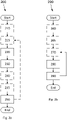
- Fig. 1 shows, in a schematic way, an example of a ventilator arrangement 1 according to the present disclosure.
- Fig. 1 has been chosen to illustrate the principle of the present disclosure. It should be emphasised that Fig. 1 is only one example and that ventilator arrangements can differ greatly. Thus, even ventilator arrangements looking schematically completely different will be within the scope of the present disclosure as long as they contain all the features of the corresponding independent claims.
- the ventilator arrangement 1 is connected to a subject 2, which here is illustrated in the form of a pair of lungs.
- the subject might, for example, be a human or an animal.
- the connection might be to the respiratory tract of the subject, for example via mouth, nose, trachea, or the like.
- the ventilator arrangement 1 can comprises pressure regulating means 3 arranged to apply a pressure to the airways of the patient 2.
- the ventilator arrangement 1 can further comprise at least one pressure and/or flow sensor 4a-4c for obtaining pressure and/or flow measurements.
- the ventilator arrangement 1 can comprise a control unit 5 for monitoring a pressure and/or flow based on the pressure and/or flow measurements obtained by the pressure and/or flow sensors 4a-4c, and/or for controlling the pressure regulating means 3 based on the monitored pressure and/or flow.
- the pressure regulating means 3 comprises a controllable inspiratory valve 3a for regulating the pressure applied to the airways of the subject 2 during inspiration.
- the pressure regulating means 3 comprises a controllable expiratory valve 3b for regulating the pressure of the airways of the subject 2 during expiration. It should be appreciated that the pressure regulating means 3 could be realised in many different ways.
- the inspiratory valve 3a may be exchanged for a blower or any other means capable of controlling the pressure to the airways of a patient.
- control unit 5 can control the inspiratory valve 3a to regulate the pressure applied to the airways of the subject 2 by regulating a flow of breathing gas supplied to the patient via an inspiratory line 6.
- the ventilator arrangement 1 can further comprise gas mixing means 7.
- the gas mixing means 7 can be coupled to one or more internal or external gas sources 8a-8c for the supply of pressurised breathing gas.
- the control unit 5 can control the expiratory valve 3b to regulate the pressure of the airways of the subject 2 by regulating a flow of exhalation gases exhaled by the subject 2 via an expiratory line 9.
- the exhalation gases are then vented out, for example to ambient air or a scavenging system through a vent 10 of the ventilator arrangement 1.
- the setup of pressure and/or flow sensors 4a-4c may vary in dependence of the intended function of the ventilator arrangement 1.
- the ventilator arrangement 1 comprises a pressure sensor 4a arranged in or close to a Y-piece 11, for example to measure a proximal pressure substantially corresponding to the airway pressure of the subject 2.
- the Y-piece 11 can connect the inspiratory line 6 and expiratory line 9 with a subject connector 12, such as a patient interface.
- the inspiratory line 6, the expiratory line 9, and the subject connector can be part of a patient circuit.
- a patient circuit can be part of a breathing circuit.
- the ventilator arrangement 1 comprises a first flow sensor 4b arranged in the inspiratory line 6 to measure the flow of gas inhaled by the subject 2.
- the ventilator arrangement 1 comprises a second flow sensor 4c arranged in the expiratory line 9 to measure the flow of gas exhaled by the subject 2.
- the pressure sensor 4a alternatively or additionally can be a flow sensor. Any of the first and/or second flow sensors 4b-c can alternatively or additionally be a pressure sensor.
- the sensors 4a-4c can be connected to the control unit 5, for example in order for the control unit to control the pressure regulating means 3, for example, based on pressure and/or flow values directly obtainable through the sensors 4a-4c, and/or derivable by the control unit 5 from the measured values.
- the control unit 5 might be configured to detect when the subject 2 wants to go from one respiratory phase to the other, i.e. from inspiration to expiration or vice versa, and to switch respiratory phase accordingly.
- the ventilator arrangement 1 is arranged to apply a set positive end-expiratory pressure, PEEP, level for performing the ventilation.
- the ventilator arrangement 1 may comprise input means 16.
- the input means 16 can be any kind of input means, such as, for example, a button, a keyboard, a switch, a touchscreen, a connection to an external input means, a mouse, a microphone, or the like.
- the input means 16 can comprise several of the aforementioned input means, such as several switches, and/or a combination of one or several of the aforementioned input means, such as switches and a touchscreen.
- the input means 16 can be arranged to receive user input.
- the input means can be arranged to transfer the user input to the control unit 5.
- the control unit can for example be an electronic circuit.
- the control unit can for example be a control computer.
- the control unit 5 can comprise a computer program stored on a memory 13 in the control unit 5.
- the computer program can cause the control unit 5 to perform partly or fully a method according to the present disclosure. Examples of such methods are described in relation to Fig. 2a and 2b .
- a method according to the present disclosure can be performed when executed by a processor 14 of the control unit 5.
- the computer program may also be installed on an external computer which may be connected to the control unit 5 of the ventilator arrangement 1 to make it perform the steps of the method.
- the ventilator arrangement 1 may comprise output means 17.
- the output means 17 can be any kind of output means, such as, for example, a screen, a display, a lamp, a speaker, a printer, a connection to an external output means, a tactile output means, such as a vibrating output means, or the like.
- the output means 17 can comprise several of the aforementioned output means, such as several lamps, and/or a combination of one or several of the aforementioned input means, such as a screen and a speaker.
- the output means 17 can be arranged to give output information to a user.
- the output means can be arranged to receive the output from the control unit 5.
- the ventilator arrangement 1 can be a ventilator arrangement for maintaining the end expiratory lung volume, EELV, of a subject when an external manoeuvre is performed on the subject ventilated by the ventilator arrangement.
- the ventilator arrangement can be arranged to perform any of the methods described in relation to Fig. 2a and 2b .
- the ventilator arrangement 1 can be arranged to determine start conditions.
- the start conditions can include at least breathing circuit leakage.
- the breathing circuit leakage can be determined, for example by the control unit, based on measurement values of the first and/or second flow sensor 4b, 4c. This is described in more detail in relation to Fig. 2a-b .
- the start conditions can comprise determining a tidal volume, TV, of the subject 2.
- the ventilator arrangement 1 can be arranged to performing a ventilation pause in the ventilation of the subject. This is preferably performed prior to the external manoeuvre. In one example, this is achieved by controlling the regulating means 3. In one example, this achieved by closing the inspiratory valve 3a and/or the expiratory valve 3b.
- the control unit 5 can thus be arranged to close the inspiratory valve 3a and/or the expiratory valve 3b for performing a ventilation pause.
- the control unit 5 can be arranged to control the inspiratory valve 3a and the expiratory valve 3b so that the flow through them is balanced for achieving a pause in ventilation.
- the ventilator arrangement 1 can be arranged to initiate the pause of the ventilation based on a user action on the input means 17.
- the ventilation pause might be initiated based on a received press on a button and/or based on a received voice command. Any other user action on any other input means might be used as well for initiating the pause of the ventilation.
- the ventilator arrangement 1 can be arranged to pause the ventilation of the subject during an expiration phase.
- the ventilator arrangement 1 can be arranged to pause the ventilation of the subject during an inspiration phase. More details regarding the pausing of ventilation are described in relation to Fig. 2a .
- the ventilator arrangement 1 can be arranged to determine a possible change in airway pressure, ⁇ Paw, of the subject during pausing of the ventilation. This is further described in relation to Fig. 2a .
- the possible change in airway pressure can be determined by the control unit 5 based on at least two measurement values from the pressure sensor 4a.
- the ventilator arrangement 1 can be arranged to resume the ventilation of the subject after the external manoeuvre.
- an updated set level for the PEEP is applied.
- the updated set level basically corresponds to the sum of the set PEEP level prior to pausing the ventilation and the determined possible change in airway pressure, ⁇ Paw, of the subject.
- the ventilator arrangement can be arranged to do the resumption at a first pre-determined time period after pausing the ventilation, and/or based on a user input, for example a user input on the input means 17. More details regarding the assumption are given in relation to Fig. 2a .
- the updated set level for the PEEP might be applied by the control unit 5.
- the ventilator arrangement 1 can be arranged to indicate the resumption of the ventilation a second pre-determined time period prior to resuming the ventilation. This indication might be performed by the output means 17, for example via a visible signal, a tactile signal and/or an audio signal.
- the ventilator arrangement 1 and/or suitable components thereof can be arranged to perform the method 200 and/or any of the steps described in relation to the method 200.
- the ventilator arrangement 1 and/or suitable components thereof can be arranged to perform the method 299 and/or any of the steps described in relation to the method 299.
- Fig. 2a shows, in a schematic way, a method 200 according to a first example of the present disclosure.
- the method 200 is a method for controlling a ventilator arrangement for maintaining the end expiratory lung volume, EELV, of a subject when an external manoeuvre is performed on the subject ventilated by the ventilator arrangement.
- the ventilator arrangement applies a set positive end-expiratory pressure, PEEP, level for performing the ventilation.
- the method 200 can be applied to control the ventilator arrangement 1 described in relation to Fig. 1 , or any other suitable ventilator arrangement.
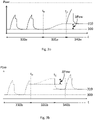
- the method 200 can, for example, partly or fully be performed by a computer program, for example a computer program at the control unit 5. Examples of a first and a second situation in which the method 200 can be used are shown in Fig. 3a and Fig. 3b , respectively.
- the method 200 is especially suitable for handling of external manoeuvres with comparably fast changes of the external pressure, such as changing position of a subject, for example putting a subject into a Trendelenburg position or back.
- the method might be stopped or paused, as will be explained later, in case this is deemed necessary during the manoeuvre, for example for adapting tubes or cables which are connected to the subject and which might need to be rearranged during a manoeuvre.
- the method 200 starts with the optional step 210.
- the optional step 210 comprises determining start conditions including at least breathing circuit leakage. It is known in the art how breathing circuit leakage of a ventilator arrangement can be determined. The practical steps to perform the determination might depend on the design of the breathing circuit. As an example, the breathing circuit leakage can be determined based on measurements from the first flow sensor 4b and the second flow sensor 4c, such as a difference between the measured flow from the first flow sensor 4b and the second flow sensor 4c over one breathing cycle. In one example the leakage is determined via a so-called insp-hold-manoeuvre, for which the inspiration is paused for a pre-determined time period, for example for 10 seconds, and for which a change in pressure is determined, for example via pressure sensor 4a. In case it is determined that the pressure has been dropped more than a pre-determined threshold it might be determined that a leakage is present.
- the first and the second situation depicted in Fig. 3a and Fig. 3b depict the airway pressure, Paw, of a subject evolving over time t.
- the time is denoted on the horizontal axis as indicated by the letter t.
- the airway pressure starts from a first base level 300, rises first during inspiration and then settles shortly on a basically constant level, which is higher than the base level 300, but generally lower than the highest value during inspiration.
- This basically constant level is often denoted inspiratory hold.
- the inspiratory hold can be considered to be part of the inspiration phase.
- the airway pressure then decreases again from the basically constant level to the base level 300 during expiration.
- a first time period 330a in the first situation consists basically of two full breathing cycles and finishes at the end of an expiration phase.
- a first time period 330b in the second situation consists roughly speaking of one and a half breathing cycles and stops at the end of an inspiration phase.
- the ventilator arrangement operates usually in normal operation mode regarding ventilation of the subject.
- the determining of the starting conditions can comprise reading stored values, for example from the memory 13.
- the ventilator arrangement might be arranged to determine the values for the start conditions at other occasions and store these values so that they are present once the method 200 is performed.
- the term "determining" can refer to a read-out procedure where a previously determined value is stored.
- the previously determined value does not necessarily need to be stored in the ventilator arrangement.
- an operator could note any previously determined values and, for example, enter any previously determined value to the ventilator arrangement at a later moment of time if needed, for example via the input means 16.
- the optional step 210 can be performed automatically.
- the optional step 210 can be performed manually.
- the optional step 210 is preferably performed prior the external manoeuvre starts. However, this is not a necessary condition. As an example, in case step 210 comprises a read-out of a stored value, this can be performed even at a later time. Step 210 is preferably performed when the ventilator arrangement is operated in normal operation mode. In the shown situations, step 210 might thus be preferably performed during the first time periods 330a, 330b, or any time earlier. The method continues with the optional step 215.
- the optional step 215 comprises receiving user input.
- the user input might be received via input means of the ventilator arrangement, such as pressing a button or the like.
- User input might be received via any of the input means 16 described in relation to Fig. 1 , or via any other means.
- the optional step 215 can also be performed prior step 210.
- step 210 might be started based on received user input.
- Step 210 might be started directly or some time period after user input is received.
- Step 215 can comprise receiving at least one time period as input, such as a value for any of the time periods described in relation to method 200.
- the method continues with step 220.
- Step 220 comprises performing a ventilation pause in the ongoing ventilation of the subject.
- the ventilation pause is performed prior to the external manoeuvre. In the first and second situation the ventilation pause is performed at a first moment of time t 0 .
- the ventilation pause might be initiated by a manual action on an input means of the ventilator arrangement.
- the ventilation pause might be initiated by receiving user input in step 215.
- the ventilation pause might start directly after user input is received.
- the ventilation pause might start a pre-determined time period after user input has been received.
- the ventilation of the subject can be paused during an expiration phase.
- the ventilation might be paused at a specific point of an expiration phase, such as the end of the expiration phase. This situation is depicted in Fig. 3a and thus part of the first situation.
- the ventilation of the subject can be paused during an inspiration phase.
- the ventilation might be paused at a specific point of an inspiration phase, such as the end of the inspiration phase.
- This situation is depicted in Fig. 3b and thus part of the second situation.
- the end of the inspiration or expiration phase might thus be specific points chosen for initiating a pause in ventilation
- any specific point might be chosen, i.e., for example, even any point in between start and end of an inspiration/expiration phase.
- the pre-determined time-period after which a ventilation pause might start might comprise a specific amount of time, such as a specific number of seconds, for example five seconds.
- the pre-determined time-period after which a ventilation pause might start might comprise a time-period until a certain event occurs, such as a time period until a specific point in the breathing cycle is reached.
- the pre-determined time period is in one example long enough so that the optional step 210 can be performed during the pre-determined time period. In one example, the optional step 210 is performed during the pre-determined time-period.
- the user input might be given when all preparations for the external manoeuvre are finished.
- the pausing of the ventilation might be indicated to a user of the ventilation arrangement, for example via output means.
- the external manoeuvre is intended to be performed after the ventilation is paused, i.e. after t 0 .
- the external manoeuvre is preferably performed during the second time period 335a, 335b.
- the second time period 335a, 335b might in practice be considerably longer than the period shown in the figures.
- the second time period might comprise several ordinary breathing cycles. It should be emphasised that the external manoeuvre generally is not performed during the whole second time period 335a, 335b as it might be impossible to directly start the external manoeuvre. However, the external manoeuvre is preferably started directly or shortly after to. The method continues with step 230.
- Step 230 comprises determining a possible change in airway pressure, ⁇ Paw, of the subject during pausing of the ventilation.
- the airway pressure might, for example, be determined via the pressure sensor 4a described in relation to Fig. 1 .
- a possible change in airway pressure can thus be determined via the difference of at least two different measurements, thus as at least two different measurements of the pressure sensor 4a.
- a first airway pressure is determined when the pausing starts, i.e. at to when referring to Fig. 3a or 3b
- a second airway pressure is determined when the ventilation is resumed, i.e. at t 1 when referring to Fig. 3a or 3b . It is in principal enough to determine the possible change in airway pressure based on these two values.
- intermediate values for ⁇ Paw can also be determined continuously and/or intermittently during the pause of the ventilation.
- the final ⁇ Paw can then be determined as the sum of the intermediate values for ⁇ Paw.
- ⁇ Paw can be positive, negative, or basically zero.
- ⁇ Paw can be positive, negative, or basically zero.
- an external manoeuvre which comprises pressurising the abdomen with CO 2 , or which comprises putting a subject in a Trendelenburg position it is expected that ⁇ Paw will be positive.
- ⁇ Paw will be negative.
- Even a so-called inverse Trendelenburg position might be used, for which the signs of ⁇ Paw will be interchanged compared to the above situation.
- the final value for ⁇ Paw determined in step 230 corresponds to the difference in airway pressure between pausing the ventilation and resuming the ventilation.
- the method continues with the optional step 240.
- the optional step 240 comprises indicating the resumption of the ventilation a second pre-determined time period prior to resuming the ventilation.
- This indication might be performed via any of the output means 17 described in relation to Fig. 1 , or via any other means.
- the indication might be via a sound and/or via a lamp, for example a blinking lamp. This can give a warning that the external manoeuvre should be finished, or at least paused, prior the resumption of the ventilation.
- the pre-determined time period is preferably chosen in such a way that enough time will be left to finish, abort, or pause the manoeuvre. As an example, the pre-determined time period might be around 1, 2, 3, 4, or 5 seconds.
- the method continues with the optional step 245.
- the optional step 245 comprises receiving user input. Anything described in relation to receiving user input in step 215 applies to step 245 as well. As an example, a user of the ventilation arrangement might give user input when the external manoeuvre is finished. The method continues with step 250.
- Step 250 comprises resuming the ventilation of the subject after the external manoeuvre.
- the ventilation is resumed at a second moment of time t 1 .
- the resumption might be initiated based on the received user input from step 245.
- the ventilation is resumed directly after the user input is received, or a pre-determined time-period afterwards. This allows resuming the ventilation as soon as the external manoeuvre is finished, so that no unnecessarily long pause of ventilation is applied to the subject.
- the resumption of the ventilation starts at a first pre-determined time period after pausing the ventilation.
- the pre-determined time period might be chosen in such a way that the subject will tolerate well the pausing of the ventilation. In the shown situations, the pre-determined time period might correspond to the second time period 335a, 335b.
- the first pre-determined time period might be determined by a user of the ventilator arrangement. The first pre-determined time period can, for example, be entered to the ventilator arrangement via input means, such as the input means 16. In one example, the first pre-determined time period might be chosen in an interval of 2-30 seconds.
- the ventilation is resumed based on the first pre-determined time period and the possible receiving of a user input, whichever might cause the earliest resumption.
- unnecessary pauses can be avoided, even if the time for performing the external manoeuvre might not be exactly foreseen.
- the ventilation is preferably resumed at the same state of the breathing cycle as when the ventilation was paused.
- the resumption of the ventilation will continue at the end of the expiration phase. This is usually the most natural choice as it usually will be most safe for the subject.
- the ventilation is resumed in the same phase of the breathing cycle as when the ventilation was paused.
- an updated set level for the PEEP is applied.
- the updated set level for the PEEP, setPEEP new basically corresponds to the sum of the set PEEP level prior to pausing the ventilation, setPEEP old , and the determined possible change in airway pressure, ⁇ Paw, of the subject.
- setPEEP new ⁇ setPEEP old + ⁇ Paw.
- the sign ⁇ is replaced by equality.
- the set PEEP level prior to pausing the ventilation can correspond to the base level 300.
- the updated set level for the PEEP can correspond to an updated base level 310. That setPEEP new and setPEEP old relate to each other as in the above equation is immediately evident in the first situation as the ventilation is paused on the base level 300, i.e. at setPEEP old , and resumed directly at the updated set PEEP level, i.e. the updated base level 310.
- the above relation applies equally well at the second situation, as the difference between the base level 300 and the updated base level corresponds basically to ⁇ Paw.
- the ventilation is then preferably continued in normal operation mode after the resumption, i.e. after t 1 . This is illustrated by the third time period 340a, 340b, where the ventilation is continued in normal operation mode, although with an updated set PEEP level.
- the method 200 ends after step 250. This might be especially suitable in case the external manoeuvre has been finished or aborted.
- the pausing is initiated by pressing a button, for example during step 215.
- the ventilation might then be paused as long as the button is pressed.
- the resumption of the ventilation is initiated by releasing the button, for example during step 245. This combination assures that a user is close to the ventilator arrangement 1 during the pausing at any time.
- the ventilation pause can be aborted, i.e. the ventilation be resumed, at any time at very short notice. This can further increase the safety of the subject as the ventilation might be resumed immediately in case any complications are discovered.
- the external manoeuvre is divided in several sub-steps with pauses in between the sub-steps.
- the method 200 can then be repeated for each sub-step of the external manoeuvre.
- the external manoeuvre might then be divided into sub-steps in such a way that the ventilation might be safely paused for the time period of each sub-step.
- the method 200 can then repeatedly be performed for each sub-step of the external manoeuvre.
- step 210 might be sufficient to perform once at the start of the method and it might thus not be needed to perform that step at every repeated run of the method 200. Even other steps might be skipped during repetition, such as any of the steps relating to receiving user input.
- the method 200 has been described above in a specific order. However, the method can also be performed in any other order and/or at least partly in parallel as long as one step does not necessarily require the finishing of a previous step.
- a ventilator arrangement according to the present disclosure, or a suitable element thereof, can be arranged to perform any of the steps described in relation to method 200.
- Fig. 2b shows, in a schematic way, a method 299 according to a second example of the present disclosure.
- the method 299 is a method for controlling a ventilator arrangement for achieving a desired end expiratory lung volume, EELV, when an external manoeuvre is performed on a subject ventilated by the ventilator arrangement.
- the ventilator arrangement applies a set positive end-expiratory pressure, PEEP, level for performing the ventilation.
- the desired EELV can be that the EELV is kept basically constant.
- the desired EELV can be a lower or a higher EELV than the current EELV.
- the desired EELV can be that the EELV is increased or decreased with a pre-determined amount.
- the desired EELV can be a desired change in the EELV.
- the method 299 is especially suitable for handling of external manoeuvres with comparably slower changes of the external pressure, such as pressurising the abdomen with CO 2 .
- the method 299 starts with the optional step 260.
- the optional step 260 comprises determining whether a leakage is present in the breathing circuit. This is performed prior performing the external manoeuvre. A warning is outputted in case the presence of a leakage has been determined. The warning might be dependent on that the leakage is above a pre-determined threshold. The determination of the leakage can be as described in relation to step 210 of method 200. The warning can be outputted via the output means 217, for example as an audio signal, a visual warning, or a tactile signal. The warning will give a user the possibility to abort the method or to try to reduce and/or to eliminate the leakage. The method continues with the optional step 265.
- the optional step 265 comprises determining an offset between inspired and expired lung volume, VTi-VTe, prior the external manoeuvre. This is in one example performed by the first and/or the second flow sensor 4b, 4c. This is in one example performed by a flow sensor at the position of the pressure sensor 4a.
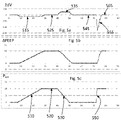
- An example of determining the offset is given in Fig. 6a-b, where different quantities are plotted over one breathing cycle.
- Fig. 6a depicts a measured flow ⁇ , for example at the position of the sensor 4a, over time t. As can be seen, the flow is first positive during a first time period 600. This corresponds to the inspiration phase of a breathing cycle. The flow is then basically constant during a second time period 610. This corresponds to the inspiratory hold period.
- the flow is then negative during a third time period 620. This corresponds to the expiration phase.
- the integration of the flow during the first time period 600, i.e. the first hatched area 630 over the first time period 600, corresponds to the inspired tidal lung volume VTi of a breathing cycle of the subject.
- the integration of the flow during the third time period 620, i.e. the second hatched area 640 over the third time period 620 corresponds to the expired tidal lung volume VTe of a breathing cycle of the subject.
- the summed up ventilation volume V at every given time t is depicted in Fig. 6b , wherein the situation of Fig. 6b corresponds to the same situation as which is depicted in Fig. 6a .
- the summed up ventilation volume V is zero and raises then during the first time period 600 until inspired tidal lung volume VTi is reached, which is indicated by the first arrow 650.
- the height of the V-curve at the first arrow 650 corresponds to the first hatched area 630.
- the summed up tidal lung volume V then falls during the third time period 620, in total with the expired tidal lung volume VTe, which is indicated by the second arrow 660.
- the difference in height of the V-curve as indicated by the second arrow 660 corresponds to the second hatched area 640.
- the inspired and the expired tidal lung volumes are not equal. This might, for example, be caused due to leakage, due to measurement errors, due to chemical or biological processes, or due to any other reasons.
- an offset might be caused by gas exchange in the lungs of the subject. The offset between inspired and expired lung volume will in the following be denoted as (VTi-VTe) offset .
- the method continues with the optional step 270.
- step 265 the external manoeuvre is preferably started after this step.
- Step 270 is also optional and if performed the external manoeuvre is preferably started in the beginning of or during step 270.
- the method will work equally well in case the external manoeuvre is started during or after the first or after several repetitions of the steps 270-290. The repetition of steps 270-290 will be described later.
- method 299 only comprises steps 280 and 290, the manoeuver is preferably started in the beginning of or during step 280. The method will work equally well in case the external manoeuvre is started during or after the first or after several repetitions of the steps 280-290.
- step 270 a flow of breathing gas to and/or from the subject is determined. This might, for example, be performed via the first and/or the second flow sensor 4b, 4c.
- the method continues with step 280.
- Step 280 comprises determining a difference between inspired and expired tidal lung volume of a breathing cycle of the subject. This can be performed in the same way as described in relation to step 265.
- the difference between inspired and expired tidal lung volume will in the following be denoted with (VTi-VTe) or (VTi-VTe) n when the difference refers to a specific run n of the method.
- the offset in step 265 relates to the fact that the external manoeuvre has not yet been started, whereas the difference in step 280 might be determined irrespective of whether the external manoeuvre has already been started or not.
- the inspired and/or expired lung volume can be determined based on the determined flow of breathing gas during step 270.
- the inspired and/or expired lung volume can also be determined in any other way.
- the method continues with step 290.
- Step 290 comprises adjusting the PEEP level after the breathing cycle of the subject based on the determined difference so that the desired EELV of the subject is achieved.
- the adjustment of the PEEP level might also be based on the determined offset.
- the offset between inspired and expired lung volume, (VTi-VTe) offset may be assumed to be zero.
- the determined difference between inspired and expired tidal lung volume of the breathing cycle can be assumed to reflect a change in end expiratory lung volume of the subject during the breathing cycle, caused by the external manoeuvre.
- the desired EELV can be a difference in EELV, set ⁇ EELV, in relation to the current EELV.
- VT denotes the tidal volume.
- Ers is determined together with (VTi-VTe) offset , for example during step 265. It should be emphasised that the above definitions of the control parameters and of Ers only are examples. Many different variations can apply and the specific definitions and the specific determination of these quantities will depend on the specific design of the ventilator arrangement.
- ⁇ VT represents the above mentioned change in end expiratory lung volume of the ventilated subject, which change is hence determined based on a difference (VTi-VTe) between inspired and expired tidal lung volume of a current breathing cycle and a determined or assumed difference ((VTi-VTe) offset ) between inspired and expired tidal lung volume of a breathing cycle prior to the external manoeuvre, herein referred to as the offset between inspired and expired lung volume.
- the offset is a non-manoeuvre induced difference between inspired and expired tidal lung volume of the ventilated subject, which offset may be measured prior to the manoeuvre (step 265) or be assumed to be zero.
- a PEEP adjustment value ⁇ PEEP
- PEEP may be adjusted to a new level, PEEP new , based on the previous PEEP level, PEEP old , and the determined PEEP adjustment value.
- the steps 280 and 290 and, optionally, the step 270 are repeated for several breathing cycles, at least during the external manoeuvre, and preferably for basically each breathing cycle during the external manoeuvre. It might be possible to "jump over" some repetitions of these steps during the external manoeuvre, but in many cases the performance of these steps during each or basically each breathing cycle will give the best results.
- the repeated steps are repeated for less than about 50 or for less than about 100 breathing cycles. This can assure that unknown small measurement errors will not add up to large deviations of the PEEP level compared to the desired behaviour.
- the repeated steps are repeated for less than 10 steps, less than 20 steps, less than 30 steps, less than 40 steps, less than 50 steps, less than 60 steps, less than 70 steps, less than 90 steps, or less than 100 steps.
- the repeated steps are repeated for less than 120 steps, less than 150 steps, less than 170 steps, or less than 200 steps.
- the method 299 ends.
- the desired number of repetitions i.e. the number of breathing cycles for which the method is performed, might be adjusted or determined by a user, for example via input means.
- the method 299 thus adapts the PEEP level after each breathing cycle without the need to pause the ventilation.
- the PEEP level is preferably adapted in such a way that the lung volume of the subject is kept constant. Thus, this method might be applied even in case a pause in ventilation might not be safely applied to the subject.
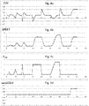
- Fig. 4a-d Examples of situations in which the method 299 can be applied are given in Fig. 4a-d and Fig. 5a- c .
- the horizontal axis denotes the number of breathing cycles.
- the vertical axis denotes a total change in lung volume of the subject in arbitrary units, wherein the change is denoted in respect to the first breathing cycle.
- the vertical axis denotes an adjustment of the PEEP level in arbitrary units. The adjustment of the PEEP level is in relation to the PEEP level of the first breathing cycle.
- the vertical axis denotes an additional pressure on the lungs of the subject in arbitrary units.
- the additional pressure is in relation to the pressure of the first breathing cycle and might originate from the external manoeuvre.
- the vertical axis denotes a desired change in setEELV. Consequently, Fig. 5a- c depict a situation in which no change in the EELV is desired. Fig. 4a-d depict all the same third situation. Fig. 5a- c depict all the same fourth situation.
- the control algorithm will adjust the PEEP level in response to the pressure exhibited to the lungs so as to maintain the EELV.
- the lung volume deviates 515 during the first, slow, rising period of the pressure only slowly from the EELV at the first breathing cycle and the PEEP level basically follows the shape of the curve in Fig. 5c with a slight delay.
- the PEEP level is with some delay kept constant as well and the difference in EELV completely compensated for 525 so that the EELV is on the same level as in the first breathing cycle.
- the falling of the external pressure is, as described above, somewhat faster than the rising.
- the PEEP delay in Fig. 5b appears again and the difference in EELV is now slightly bigger 535 due to the faster change in the pressure.
- the PEEP level gets constant as well and the difference in EELV does eventually appear again 545.
- the second, short, rise of external pressure causes again a delay in adjusting the PEEP level and, due to the faster rising of the pressure, for some breathing cycles a larger difference 555 in EELV before the control algorithm has adapted the PEEP level and the difference in EELV has disappeared again 565.
- the PEEP level is not adapted instantaneously and the EELV is not instantaneously kept constant. This is due to the control algorithm.
- the time of adaptation and/or the difference can depend on the speed of changing the external pressure. However, eventually the adaptation of the PEEP level is performed and the difference in EELV will disappear after a relatively short number of breathing cycles.
- Fig. 4a-d depict a third situation in which the method 299 is used.
- the graphs in these figures behave in the same way as described in relation to the fourth situation.
- the control algorithm might affect the PEEP level and the difference in EELV in case the rising and falling of the external pressure does not only appear at different "speed", but also up to different heights and/or without first remaining on a stable level before falling again.
- a new set level for the EELV is desired, as indicated in Fig. 4d .
- This is without any change in the external pressure as can be seen in Fig. 4c .
- the control algorithm rises the PEEP level although no change in the external pressure appears. Due to rising of the PEEP level and due to the absence of a change in external pressure to the lungs, a deviation in the EELV appears, as can be seen in Fig. 4a , and eventually remains, as desired by the new set level for the EELV in Fig. 4d .
- the method 299 can perform any of the features described in relation to Fig. 4a-d and Fig. 5a- c .
- a ventilator arrangement according to the present disclosure can be arranged to perform any of the steps described in relation to method 299.
- the first method 200 for maintaining the end expiratory lung volume of the ventilated subject by adjusting PEEP based on a change in airway pressure determined during a ventilation paus may be advantageously combined with the second method 299 ( Fig. 2b ) for achieving a desired end expiratory lung volume of the ventilated subject by adjusting PEEP based on a difference between inspired and expired tidal lung volume of a breathing cycle of the subject.
- the first method for trying to maintain the end expiratory lung volume of the subject during the external manoeuvre and to apply the second method during a final phase of the external manoeuvre and/or after the external manoeuvre, after having resumed ventilation of the subject with the updated set level for PEEP determined in accordance with the first method.
- any change in end expiratory lung volume caused by the external manoeuvre and not fully compensated for by the first method, or any retroactive effect on the end expiratory lung volume of the subject caused by the external manoeuvre but occurring after having performed the first method can be detected and compensated for by the second method.
- the second method may serve to ensure that the EELV of the subject is maintained at a substantially constant level after resuming ventilation of the subject with the updated set level for PEEP.
- the second method may also be performed after the first method in order to change, in a controlled manner, the EELV of the subject to a new desired EELV of the subject following the external manoeuvre.
- a method for controlling a ventilator arrangement for achieving a desired EELV of the subject when an external manoeuvre is performed on a subject ventilated by the ventilator arrangement, wherein the ventilator arrangement applies a set PEEP level for performing the ventilation comprising the steps of:
- the desired EELV may be a new desired EELV or an EELV corresponding to the EELV of the subject prior to the external manoeuvre.
- Steps d) and e) are performed, and typically repeatedly performed, after resuming ventilation of the subject in step c).
- steps a)-c) may be performed during the external manoeuvre whereas steps d) and e) are performed, and typically repeatedly performed, after the external manoeuvre.
- steps a)-c) may be performed during a first phase of the external manoeuvre whereas steps d) and e) are performed, and typically repeatedly performed, during a second and final phase of the external manoeuvre and/or after the external manoeuvre.
- Steps a)-c) correspond to method steps of the first method 200 described above with reference to Fig. 2a
- steps d)-e) correspond to method steps of the second method 299 described above with reference to Fig. 2b . It should thus be realised that steps a)-c) may be performed in accordance with any of the teachings described above with reference to Fig. 2a
- steps d)-e) may be performed in accordance with any of the teachings described above with reference to Fig. 2b .
- the method may comprise the steps of determining a change in end expiratory lung volume of the subject based on the determined difference between inspired and expired tidal lung volume, and adjusting the PEEP level after the breathing cycle of the subject based on the determined change in end expiratory lung volume.
- It may also comprise the steps of determining or assuming an offset between inspired and expired lung volume of the subject prior to the external manoeuvre, and determining the change in end-expiratory lung volume of the subject based on the determined difference between inspired and expired tidal lung volume and the determined or assumed offset.
- the step of adjusting the PEEP level may comprise the steps of determining a PEEP adjustment value, ⁇ PEEP, based on the determined change in end expiratory lung volume of the subject and the desired constant EELV of the subject, and adjusting the PEEP level to a new PEEP level based on a previous PEEP level and the PEEP adjustment value.
- a computer program product comprising instructions which, when the program is executed by a computer, cause the computer to carry out the above-described method steps a)-e).
- a computer-readable medium comprising instructions which, when executed by a computer, cause the computer to carry out the above described method steps a)-e).
- the computer may be a computer of the control unit 5 of the ventilator arrangement 1 (see Fig. 1 ) or an external computer which may be connected to the control unit 5.
- a ventilator arrangement 1 for achieving a desired EELV of a subject when an external manoeuvre is performed on the subject ventilated by the ventilator arrangement, the ventilator arrangement being arranged to apply a set PEEP level for performing the ventilation, the ventilator arrangement further being arranged to:
Description
- The present disclosure relates to a ventilator arrangement and to a computer program product.
- When using extrathoracic forces or any other external manoeuvre affecting the abdomen it is important to maintain the end expiratory lung volume of a subject. An example might be the changing of position of a subject from horizontal position to the so-called Trendelenburg position. In this case, the weight of the abdomen will expose extra pressure to the diaphragm and thus the lungs, so that the lung volume might get affected. Another example might be pressurising the abdomen with CO2 during laparoscopic surgery which might affect the lung volume due to the extra pressure from the abdomen which exposes the lungs. During an external manoeuvre, such as those described above, the subject might be connected to a ventilator arrangement, for example in preparation for surgery.
- In case the lung volume is not maintained during external manoeuvres, regions of the lung might collapse which in its turn requires extra resources for recovering the lung. Further, a lung collapse might require a lung recruitment manoeuvre adding unnecessary stress on the lung tissue, and should thus be avoided. There is thus a need to operate a ventilator arrangement in such a way as to assure that the end expiratory lung volume, EELV, of a subject is maintained when an external manoeuvre is performed on the subject, or, in general, that a desired EELV is achieved in this case.
- The ventilator arrangement might provide functionality to apply a set level for positive end-expiratory pressure, PEEP. When using such a ventilator arrangement, it is desirable that the ventilator arrangement is controlled in such a way that the end expiratory lung volume and/or the lung compliance achieved by the PEEP-setting is/are maintained even during and after the external manoeuvre.
-
US2017/028145 A1 discloses a method of ventilating a patient. The method comprises measuring a patient physiological parameter while the patient is in a first position and recording the measured patient physiological parameter as a baseline. The method further comprises tilting the patient from the first position to a second position and measuring the patient physiological parameter when the patient is in the second position. The method further comprises performing an action based on a change in the measured physiological parameter from the baseline when the patient is in the second position. The action is at least one of modifying a ventilation parameter, generating an alert, and providing a recommendation. - It is thus an objective to provide a ventilator arrangement and a computer program product which maintain the end expiratory lung volume, EELV, of a subject when an external manoeuvre is performed on the subject ventilated by the ventilator arrangement.
- It is an objective to provide a ventilator arrangement and a computer program product which achieve a desired end expiratory lung volume, EELV, when an external manoeuvre is performed on a subject ventilated by the ventilator arrangement.
- It is a further objective of the present disclosure to provide an alternative ventilator arrangement and an alternative computer program product.
- It is yet a further objective of the present disclosure to provide a ventilator arrangement and a computer program product which reduces needs and/or time for personal to adjust settings of a ventilator arrangement in connection to performing an external manoeuvre at the subject.
- It is yet a further objective of the present disclosure to provide a ventilator arrangement and a computer program product which reduces potential needs for any recovery measures at the subject when or after performing an external manoeuvre at the subject.
- It is also disclosed a method for controlling a ventilator arrangement for maintaining the end expiratory lung volume, EELV, of a subject when an external manoeuvre is performed on the subject ventilated by the ventilator arrangement. The ventilator arrangement applies a set positive end-expiratory pressure, PEEP, level for performing the ventilation. The method comprises the step of performing a ventilation pause in the ongoing ventilation of the subject prior to the external manoeuvre. The method further comprises the step of determining a possible change in airway pressure (ΔPaw) of the subject during pausing of the ventilation. The method even further comprises the step of resuming the ventilation of the subject after at least parts of the external manoeuvre. Therein an updated set level for the PEEP is applied. The updated set level basically corresponds to the sum of the set PEEP level prior to pausing the ventilation and the determined possible change in airway pressure (ΔPaw) of the subject.
- In this way the method takes care of potential changes in the pressure to which the lungs are exposed to. The EELV is thus maintained. Thus, the risk of lung collapses and the need for lung recovery is reduced. Further, the ventilator arrangement can take care of the adaption itself without the need from the personal to change set-values of the ventilator arrangement. Even further, an adaption of the PEEP-level can be provided without any delay. Thus complexity is reduced. Further, a situation is created which allows performing an external manoeuvre at the subject in a safer way.
- In one example, the pausing of the ventilation is initiated by a manual action on an input means of the ventilator arrangement. This allows the personal to reduce the amount of time for which the ventilation is paused, for example by initiation that part of the method only when the subject is ready for the external manoeuvre.
- In one example, the resumption of the ventilation starts at a first pre-determined time period after pausing the ventilation. This assures that the ventilation is not paused too long. This helps reducing or avoiding risks to the subject by pausing of the ventilation.
- In one example, the method further comprises the step of indicating the resumption of the ventilation a second pre-determined time period prior to resuming the ventilation. This can warn the personal that the external manoeuvre has to come to an end, or at least to a pause. This avoids or reduces the risks to the subject which might be caused by a pause in ventilation and/or the external manoeuvre itself.
- In one example, the resumption of the ventilation is initiated by a manual action on an input means of the ventilator arrangement. This allows giving the personal full control of the time when the ventilator arrangement resumes ventilation. Thus a high flexibility is achieved. Further, in case the external manoeuvre is performed faster than expected, the ventilation might be resumed earlier. Thus the pause in ventilation can be reduced to a minimum.
- In one example, the ventilation of the subject is paused during an expiration phase. This usually implies that the thoracic pressure is comparably smaller, which can give advantages from a haemodynamic point of view. The ventilation can be paused at the end of the expiration phase or at any other time during the expiration phase.
- In one example, the ventilation of the subject is paused during an inspiration phase. Since there is usually more air in the lungs during inspiration, especially at the end of an inspiration phase, the subject might tolerate a larger ventilation pause in a safer way. The ventilation can be paused at the end of the inspiration phase or at any other time during the inspiration phase.
- In one example, the external manoeuvre is divided in several sub-steps with pauses in between the sub-steps. The method is repeated for each sub-step of the external manoeuvre. This allows using the method even for external manoeuvres requiring a longer time period. As an example, in case the time period of the external manoeuvre might exceed the time period for which the ventilation of the subject safely can be paused, the division into sub-steps, where each subject has a suitable time length, such as a time length not exceeding the time length for which the ventilation of the subject can be safely paused, might allow still using the method although the comparably long manoeuvre.
- In one example, the method comprises the step of determining start conditions including at least breathing circuit leakage. This can provide a more accurate method.
- In one example, the start conditions also include determining a tidal volume, TV, of the subject. This might be a useful quantity for improving accuracy of the method.
- At least some of the objectives are also achieved by a ventilator arrangement for maintaining the end expiratory lung volume, EELV, of a subject when an external manoeuvre is performed on the subject ventilated by the ventilator arrangement. The ventilator arrangement is arranged to apply a set positive end-expiratory pressure, PEEP, level for performing the ventilation. The ventilator arrangement is further arranged to performing a ventilation pause in the ventilation of the subject prior to the external manoeuvre. The ventilator arrangement is even further arranged to determining a possible change in airway pressure (ΔPaw) of the subject during pausing of the ventilation. The ventilator arrangement is yet even further arranged to resuming the ventilation of the subject after at least parts of the external manoeuvre. Thereby an updated set level for the PEEP is applied. The updated set level basically corresponds to the sum of the set PEEP level prior to pausing the ventilation and the determined possible change in airway pressure (ΔPaw) of the subject.
- In one embodiment, the ventilator arrangement is arranged to initiate the pause of the ventilation based on a manual action on an input means of the ventilator arrangement.
- In one embodiment, the ventilator arrangement is arranged to resume the ventilation at a first pre-determined time period after pausing the ventilation.
- In one embodiment, the ventilator arrangement is arranged to indicate the resumption of the ventilation a second pre-determined time period prior to resuming the ventilation.
- In one embodiment, the ventilator arrangement is arranged to initiate the resumption of the ventilation based on a manual action on an input means of the ventilator arrangement.
- In one embodiment, the ventilator arrangement is arranged to pause the ventilation of the subject during an expiration phase. In one embodiment, the ventilator arrangement is arranged to pause the ventilation of the subject at the end of an expiration phase.
- In one embodiment, the ventilator arrangement is arranged to pause the ventilation of the subject during an inspiration phase. In one embodiment, the ventilator arrangement is arranged to pause the ventilation of the subject at the end of an inspiration phase.
- In one embodiment, the ventilator arrangement is arranged to determine start conditions including at least breathing circuit leakage.
- In one embodiment, the start conditions also include determining a tidal volume, TV, of the subject.
- At least some of the objectives are also achieved by a computer program product, comprising instructions which, when the program is executed by a computer, cause the computer to carry out the method for controlling a ventilator arrangement for maintaining the end expiratory lung volume, EELV, of a subject according to the present disclosure.
- It is also disclosed a computer-readable medium comprising instructions which, when executed by a computer, cause the computer to carry out the method for controlling a ventilator arrangement for maintaining the end expiratory lung volume, EELV, of a subject according to the present disclosure.
- It is also disclosed a method for controlling a ventilator arrangement for achieving a desired end expiratory lung volume, EELV, when an external manoeuvre is performed on a subject ventilated by the ventilator arrangement. The ventilator arrangement applies a set positive end-expiratory pressure, PEEP, level for performing the ventilation. The method comprises the step of determining a difference between inspired and expired tidal lung volume of a breathing cycle of the subject. The method further comprises the step of adjusting the PEEP level after the breathing cycle of the subject based on the determined difference so that the desired EELV of the subject is achieved. The steps are repeated for several breathing cycles during and/or after the external manoeuvre. Preferably, the steps are repeated for several breathing cycles during the external manoeuvre, and most preferably for basically each breathing cycle during the external manoeuvre.
- This allows achieving a desired EELV without the need to pause the ventilation. Thus, the method can be applied even when the ventilator arrangement is used for subjects who cannot safely bear a pausing in the ventilation. The desired EELV might be to keep the EELV constant. The risk of lung collapses and the need for lung recovery is reduced. Further, the ventilator arrangement can take care of the adaption itself without the need from the personnel to find out suitable set-values for the ventilator arrangement. Thus complexity is reduced. Further, a situation is created which allows performing an external manoeuvre at the subject in a safer way.
- In one example, the desired EELV is that the EELV is kept basically constant.
- In one example, the desired EELV is that the EELV is increased or decreased with a pre-determined amount. This is especially useful in case it is determined that external manoeuvre will require or at least recommend a higher or lower EELV after the performance of the manoeuvre.
- In one example, the method further comprises the steps of determining a change in end expiratory lung volume of the subject based on the determined difference between inspired and expired tidal lung volume, and adjusting the PEEP level after the breathing cycle of the subject based on the determined change in end expiratory lung volume.
- The change in end expiratory lung volume may be determined based on the determined difference between inspired and expired tidal lung volume and a determined or assumed offset between inspired and expired lung volume of the subject prior to the external manoeuvre. The offset may be assumed to be zero, in which case the change in end expiratory lung volume may be assumed to correspond to the determined difference between inspired and expired tidal lung volume. In other situations, the offset between inspired and expired tidal lung volume may be determined prior to the external manoeuvre. By determining the offset prior to the external manoeuvre and adjusting the PEEP level also based on the determined offset, potential leakage in the ventilator arrangement can be compensated for in a relatively easy manner.
- In one example, the method further comprises the step of determining whether a leakage is present in the breathing circuit prior performing the external manoeuvre and outputting a warning in case the presence of a leakage has been determined. This allows for the personal to be extra careful during the external manoeuvre, to not perform the external manoeuvre, or to first trying decreasing the leakage prior performing the manoeuvre.
- In one example, the method further comprises the step of determining a flow of breathing gas to and/or from the subject. The inspired and/or expired lung volume is determined based on the determined flow of breathing gas. This provides a practical way for determining the inspired and/or expired breathing gas.
- In one example, the repeated steps are repeated for less than about 50 or for less than about 100 breathing cycles. This reduces the risks of potential measurement errors, such as systematic measurement errors. Especially potential measurement errors in determining the difference between inspired and expired tidal lung volume of a breathing cycle of the subject might add up over several breathing cycles. Thus, repeating the method for not too many iterations might increase the safety for the subject.
- At least some of the objectives are also achieved by a ventilator arrangement. The ventilator arrangement is arranged to apply a set positive end-expiratory pressure, PEEP, level for performing a ventilation of a subject. The ventilator arrangement is further arranged to determine a difference between inspired and expired tidal lung volume of a breathing cycle of the subject. The ventilator arrangement is even further arranged to adjust the PEEP level after the breathing cycle of the subject based on the determined difference so that a desired end expiratory lung volume, EELV, of the patient is achieved. The ventilator arrangement is arranged to perform the determining and the adjusting repeatedly for several breathing cycles during and/or after the external manoeuvre. Preferably, the steps are repeated for several breathing cycles during the external manoeuvre, and most preferably for basically each breathing cycle during the external manoeuvre.
- The ventilator arrangement may be arranged to determine a change in end expiratory lung volume of the subject based on the determined difference between inspired and expired tidal lung volume and to adjust the PEEP level after the breathing cycle of the subject based on the determined change in end expiratory lung volume, in accordance with the above described principles.
- In one embodiment, the desired EELV is that the lung volume is kept basically constant.
- In one embodiment, the desired EELV is that the lung volume is increased or decreased with a pre-determined amount.
- In one embodiment, the ventilator arrangement is further arranged to determine an offset between inspired and expired lung volume (VTi-VTE) prior the external manoeuvre. The adjusting of the PEEP level is also based on the determined offset.
- In one embodiment, the ventilator arrangement is arranged to determine whether a leakage is present in the breathing circuit prior performing the external manoeuvre and to output a warning in case the presence of a leakage has been determined.
- In one embodiment, the ventilator arrangement is arranged to determine a flow of breathing gas to and/or from the subject. The ventilator arrangement is further arranged to determine the inspired and/or expired lung volume based on the determined flow of breathing gas.
- In one embodiment, the ventilator arrangement is arranged to repeat the repeatedly performed steps for less than about 50 or for less than about 100 breathing cycles.
- At least some of the objectives are also achieved by a computer program product, comprising instructions which, when the program is executed by a computer, cause the computer to carry out the method for controlling a ventilator arrangement for achieving a desired end expiratory lung volume, EELV, when an external manoeuvre is performed on a subject ventilated by the ventilator arrangement according to the present disclosure.
- It is also disclosed a computer-readable medium comprising instructions which, when executed by a computer, cause the computer to carry out the method for controlling a ventilator arrangement for achieving a desired end expiratory lung volume, EELV, when an external manoeuvre is performed on a subject ventilated by the ventilator arrangement according to the present disclosure.
- The ventilator arrangement, the computer program product and the computer-readable storage medium have corresponding advantages as have been described in connection with the corresponding examples of the corresponding method according to this disclosure. Further advantages of the present invention are described in the following detailed description and/or will arise to a person skilled in the art when performing the invention.
- The present invention is defined by the appended claims.
- For a more detailed understanding of the present invention and its objects and advantages, reference is made to the following detailed description which should be read together with the accompanying drawings. Same reference numbers refer to same components in the different figures. In the following,
-
Fig. 1 shows, in a schematic way, an example of a ventilator arrangement; -
Fig. 2a shows, in a schematic way, a method according to a first example of the present disclosure; -
Fig. 2b shows, in a schematic way, a method according to a second example of the present disclosure; and -
Fig. 3a shows, in a schematic way, an example of a first situation in which a method according to the first example of the present disclosure can be used; -
Fig. 3b shows, in a schematic way, an example of a second situation in which a method according to the first example of the present disclosure can be used; -
Fig. 4a-d show, in a schematic way, an example of a third situation in which a method according to the second example of the present disclosure can be used; - Fig. 5a-
c show, in a schematic way, an example of a fourth situation in which a method according to the second example of the present disclosure can be used; and - Fig. 6a-b show, in a schematic way, an example of a how physical quantities can evolve when using a method according to the second example of the present disclosure.
-
Fig. 1 shows, in a schematic way, an example of aventilator arrangement 1 according to the present disclosure.Fig. 1 has been chosen to illustrate the principle of the present disclosure. It should be emphasised thatFig. 1 is only one example and that ventilator arrangements can differ greatly. Thus, even ventilator arrangements looking schematically completely different will be within the scope of the present disclosure as long as they contain all the features of the corresponding independent claims. Theventilator arrangement 1 is connected to asubject 2, which here is illustrated in the form of a pair of lungs. The subject might, for example, be a human or an animal. The connection might be to the respiratory tract of the subject, for example via mouth, nose, trachea, or the like. - The
ventilator arrangement 1 can comprises pressure regulating means 3 arranged to apply a pressure to the airways of thepatient 2. Theventilator arrangement 1 can further comprise at least one pressure and/or flowsensor 4a-4c for obtaining pressure and/or flow measurements. Furthermore, theventilator arrangement 1 can comprise acontrol unit 5 for monitoring a pressure and/or flow based on the pressure and/or flow measurements obtained by the pressure and/orflow sensors 4a-4c, and/or for controlling the pressure regulating means 3 based on the monitored pressure and/or flow. - In one example, the pressure regulating means 3 comprises a controllable
inspiratory valve 3a for regulating the pressure applied to the airways of the subject 2 during inspiration. In one example, the pressure regulating means 3 comprises a controllableexpiratory valve 3b for regulating the pressure of the airways of the subject 2 during expiration. It should be appreciated that the pressure regulating means 3 could be realised in many different ways. For example, theinspiratory valve 3a may be exchanged for a blower or any other means capable of controlling the pressure to the airways of a patient. - During inspiration, the
control unit 5 can control theinspiratory valve 3a to regulate the pressure applied to the airways of the subject 2 by regulating a flow of breathing gas supplied to the patient via aninspiratory line 6. Theventilator arrangement 1 can further comprise gas mixing means 7. The gas mixing means 7 can be coupled to one or more internal orexternal gas sources 8a-8c for the supply of pressurised breathing gas. - During expiration, the
control unit 5 can control theexpiratory valve 3b to regulate the pressure of the airways of the subject 2 by regulating a flow of exhalation gases exhaled by thesubject 2 via anexpiratory line 9. The exhalation gases are then vented out, for example to ambient air or a scavenging system through avent 10 of theventilator arrangement 1. The setup of pressure and/orflow sensors 4a-4c may vary in dependence of the intended function of theventilator arrangement 1. In one embodiment, theventilator arrangement 1 comprises apressure sensor 4a arranged in or close to a Y-piece 11, for example to measure a proximal pressure substantially corresponding to the airway pressure of thesubject 2. The Y-piece 11 can connect theinspiratory line 6 andexpiratory line 9 with asubject connector 12, such as a patient interface. - The
inspiratory line 6, theexpiratory line 9, and the subject connector can be part of a patient circuit. A patient circuit can be part of a breathing circuit. In one embodiment, theventilator arrangement 1 comprises afirst flow sensor 4b arranged in theinspiratory line 6 to measure the flow of gas inhaled by thesubject 2. In one embodiment, theventilator arrangement 1 comprises asecond flow sensor 4c arranged in theexpiratory line 9 to measure the flow of gas exhaled by thesubject 2. It should be emphasised that thepressure sensor 4a alternatively or additionally can be a flow sensor. Any of the first and/orsecond flow sensors 4b-c can alternatively or additionally be a pressure sensor. Although not shown in the drawing it should be appreciated that thesensors 4a-4c can be connected to thecontrol unit 5, for example in order for the control unit to control the pressure regulating means 3, for example, based on pressure and/or flow values directly obtainable through thesensors 4a-4c, and/or derivable by thecontrol unit 5 from the measured values. - The
control unit 5 might be configured to detect when the subject 2 wants to go from one respiratory phase to the other, i.e. from inspiration to expiration or vice versa, and to switch respiratory phase accordingly. - The
ventilator arrangement 1 is arranged to apply a set positive end-expiratory pressure, PEEP, level for performing the ventilation. - The
ventilator arrangement 1 may comprise input means 16. The input means 16 can be any kind of input means, such as, for example, a button, a keyboard, a switch, a touchscreen, a connection to an external input means, a mouse, a microphone, or the like. The input means 16 can comprise several of the aforementioned input means, such as several switches, and/or a combination of one or several of the aforementioned input means, such as switches and a touchscreen. The input means 16 can be arranged to receive user input. The input means can be arranged to transfer the user input to thecontrol unit 5. The control unit can for example be an electronic circuit. The control unit can for example be a control computer. - The
control unit 5 can comprise a computer program stored on amemory 13 in thecontrol unit 5. The computer program can cause thecontrol unit 5 to perform partly or fully a method according to the present disclosure. Examples of such methods are described in relation toFig. 2a and 2b . As an example, a method according to the present disclosure can be performed when executed by aprocessor 14 of thecontrol unit 5. The computer program may also be installed on an external computer which may be connected to thecontrol unit 5 of theventilator arrangement 1 to make it perform the steps of the method. - The
ventilator arrangement 1 may comprise output means 17. The output means 17 can be any kind of output means, such as, for example, a screen, a display, a lamp, a speaker, a printer, a connection to an external output means, a tactile output means, such as a vibrating output means, or the like. The output means 17 can comprise several of the aforementioned output means, such as several lamps, and/or a combination of one or several of the aforementioned input means, such as a screen and a speaker. The output means 17 can be arranged to give output information to a user. The output means can be arranged to receive the output from thecontrol unit 5. - The
ventilator arrangement 1 can be a ventilator arrangement for maintaining the end expiratory lung volume, EELV, of a subject when an external manoeuvre is performed on the subject ventilated by the ventilator arrangement. - The ventilator arrangement can be arranged to perform any of the methods described in relation to
Fig. 2a and 2b . - The
ventilator arrangement 1 can be arranged to determine start conditions. The start conditions can include at least breathing circuit leakage. As an example, the breathing circuit leakage can be determined, for example by the control unit, based on measurement values of the first and/orsecond flow sensor Fig. 2a-b . The start conditions can comprise determining a tidal volume, TV, of thesubject 2. - The
ventilator arrangement 1 can be arranged to performing a ventilation pause in the ventilation of the subject. This is preferably performed prior to the external manoeuvre. In one example, this is achieved by controlling the regulating means 3. In one example, this achieved by closing theinspiratory valve 3a and/or theexpiratory valve 3b. Thecontrol unit 5 can thus be arranged to close theinspiratory valve 3a and/or theexpiratory valve 3b for performing a ventilation pause. Thecontrol unit 5 can be arranged to control theinspiratory valve 3a and theexpiratory valve 3b so that the flow through them is balanced for achieving a pause in ventilation. - The
ventilator arrangement 1 can be arranged to initiate the pause of the ventilation based on a user action on the input means 17. As an example, the ventilation pause might be initiated based on a received press on a button and/or based on a received voice command. Any other user action on any other input means might be used as well for initiating the pause of the ventilation. - The
ventilator arrangement 1 can be arranged to pause the ventilation of the subject during an expiration phase. Theventilator arrangement 1 can be arranged to pause the ventilation of the subject during an inspiration phase. More details regarding the pausing of ventilation are described in relation toFig. 2a . - The
ventilator arrangement 1 can be arranged to determine a possible change in airway pressure, ΔPaw, of the subject during pausing of the ventilation. This is further described in relation toFig. 2a . As an example, the possible change in airway pressure can be determined by thecontrol unit 5 based on at least two measurement values from thepressure sensor 4a. - The
ventilator arrangement 1 can be arranged to resume the ventilation of the subject after the external manoeuvre. When resuming, an updated set level for the PEEP is applied. The updated set level basically corresponds to the sum of the set PEEP level prior to pausing the ventilation and the determined possible change in airway pressure, ΔPaw, of the subject. When resuming the ventilation, the ventilator arrangement can be arranged to do the resumption at a first pre-determined time period after pausing the ventilation, and/or based on a user input, for example a user input on the input means 17. More details regarding the assumption are given in relation toFig. 2a . As an example, the updated set level for the PEEP might be applied by thecontrol unit 5. - The
ventilator arrangement 1 can be arranged to indicate the resumption of the ventilation a second pre-determined time period prior to resuming the ventilation. This indication might be performed by the output means 17, for example via a visible signal, a tactile signal and/or an audio signal. - The
ventilator arrangement 1 and/or suitable components thereof can be arranged to perform themethod 200 and/or any of the steps described in relation to themethod 200. Theventilator arrangement 1 and/or suitable components thereof can be arranged to perform themethod 299 and/or any of the steps described in relation to themethod 299. -
Fig. 2a shows, in a schematic way, amethod 200 according to a first example of the present disclosure. - The
method 200 is a method for controlling a ventilator arrangement for maintaining the end expiratory lung volume, EELV, of a subject when an external manoeuvre is performed on the subject ventilated by the ventilator arrangement. Herein, the ventilator arrangement applies a set positive end-expiratory pressure, PEEP, level for performing the ventilation. Themethod 200 can be applied to control theventilator arrangement 1 described in relation toFig. 1 , or any other suitable ventilator arrangement. Themethod 200 can, for example, partly or fully be performed by a computer program, for example a computer program at thecontrol unit 5. Examples of a first and a second situation in which themethod 200 can be used are shown inFig. 3a and Fig. 3b , respectively. Themethod 200 is especially suitable for handling of external manoeuvres with comparably fast changes of the external pressure, such as changing position of a subject, for example putting a subject into a Trendelenburg position or back. However, the method might be stopped or paused, as will be explained later, in case this is deemed necessary during the manoeuvre, for example for adapting tubes or cables which are connected to the subject and which might need to be rearranged during a manoeuvre. Themethod 200 starts with theoptional step 210. - The
optional step 210 comprises determining start conditions including at least breathing circuit leakage. It is known in the art how breathing circuit leakage of a ventilator arrangement can be determined. The practical steps to perform the determination might depend on the design of the breathing circuit. As an example, the breathing circuit leakage can be determined based on measurements from thefirst flow sensor 4b and thesecond flow sensor 4c, such as a difference between the measured flow from thefirst flow sensor 4b and thesecond flow sensor 4c over one breathing cycle. In one example the leakage is determined via a so-called insp-hold-manoeuvre, for which the inspiration is paused for a pre-determined time period, for example for 10 seconds, and for which a change in pressure is determined, for example viapressure sensor 4a. In case it is determined that the pressure has been dropped more than a pre-determined threshold it might be determined that a leakage is present. - The first and the second situation depicted in
Fig. 3a and Fig. 3b depict the airway pressure, Paw, of a subject evolving over time t. The time is denoted on the horizontal axis as indicated by the letter t. In the shown situations, the airway pressure starts from afirst base level 300, rises first during inspiration and then settles shortly on a basically constant level, which is higher than thebase level 300, but generally lower than the highest value during inspiration. This basically constant level is often denoted inspiratory hold. The inspiratory hold can be considered to be part of the inspiration phase. The airway pressure then decreases again from the basically constant level to thebase level 300 during expiration. Thus, afirst time period 330a in the first situation consists basically of two full breathing cycles and finishes at the end of an expiration phase. Afirst time period 330b in the second situation consists roughly speaking of one and a half breathing cycles and stops at the end of an inspiration phase. During thefirst time periods - The determining of the starting conditions can comprise reading stored values, for example from the
memory 13. As an example, the ventilator arrangement might be arranged to determine the values for the start conditions at other occasions and store these values so that they are present once themethod 200 is performed. Thus, the term "determining" can refer to a read-out procedure where a previously determined value is stored. The previously determined value does not necessarily need to be stored in the ventilator arrangement. As an example, an operator could note any previously determined values and, for example, enter any previously determined value to the ventilator arrangement at a later moment of time if needed, for example via the input means 16. - The
optional step 210 can be performed automatically. Theoptional step 210 can be performed manually. - The
optional step 210 is preferably performed prior the external manoeuvre starts. However, this is not a necessary condition. As an example, incase step 210 comprises a read-out of a stored value, this can be performed even at a later time. Step 210 is preferably performed when the ventilator arrangement is operated in normal operation mode. In the shown situations, step 210 might thus be preferably performed during thefirst time periods optional step 215. - The
optional step 215 comprises receiving user input. The user input might be received via input means of the ventilator arrangement, such as pressing a button or the like. User input might be received via any of the input means 16 described in relation toFig. 1 , or via any other means. Theoptional step 215 can also be performedprior step 210. As an example, step 210 might be started based on received user input. Step 210 might be started directly or some time period after user input is received. Step 215 can comprise receiving at least one time period as input, such as a value for any of the time periods described in relation tomethod 200. The method continues withstep 220. - Step 220 comprises performing a ventilation pause in the ongoing ventilation of the subject. The ventilation pause is performed prior to the external manoeuvre. In the first and second situation the ventilation pause is performed at a first moment of time t0. The ventilation pause might be initiated by a manual action on an input means of the ventilator arrangement. The ventilation pause might be initiated by receiving user input in
step 215. The ventilation pause might start directly after user input is received. The ventilation pause might start a pre-determined time period after user input has been received. - The ventilation of the subject can be paused during an expiration phase. The ventilation might be paused at a specific point of an expiration phase, such as the end of the expiration phase. This situation is depicted in
Fig. 3a and thus part of the first situation. - The ventilation of the subject can be paused during an inspiration phase. The ventilation might be paused at a specific point of an inspiration phase, such as the end of the inspiration phase. This situation is depicted in
Fig. 3b and thus part of the second situation. The end of the inspiration or expiration phase might thus be specific points chosen for initiating a pause in ventilation However, in principle, in case a specific point of a breathing cycle is chosen, any specific point might be chosen, i.e., for example, even any point in between start and end of an inspiration/expiration phase. - The pre-determined time-period after which a ventilation pause might start might comprise a specific amount of time, such as a specific number of seconds, for example five seconds. The pre-determined time-period after which a ventilation pause might start might comprise a time-period until a certain event occurs, such as a time period until a specific point in the breathing cycle is reached. The pre-determined time period is in one example long enough so that the
optional step 210 can be performed during the pre-determined time period. In one example, theoptional step 210 is performed during the pre-determined time-period. - By initiating the pausing by receiving user input, flexibility is achieved. As an example, the user input might be given when all preparations for the external manoeuvre are finished. The pausing of the ventilation might be indicated to a user of the ventilation arrangement, for example via output means.
- The external manoeuvre is intended to be performed after the ventilation is paused, i.e. after t0. In the shown situations, the external manoeuvre is preferably performed during the
second time period second time period second time period step 230. - Step 230 comprises determining a possible change in airway pressure, ΔPaw, of the subject during pausing of the ventilation. The airway pressure might, for example, be determined via the
pressure sensor 4a described in relation toFig. 1 . A possible change in airway pressure can thus be determined via the difference of at least two different measurements, thus as at least two different measurements of thepressure sensor 4a. In one example, a first airway pressure is determined when the pausing starts, i.e. at to when referring toFig. 3a or 3b , and a second airway pressure is determined when the ventilation is resumed, i.e. at t1 when referring toFig. 3a or 3b . It is in principal enough to determine the possible change in airway pressure based on these two values. However, intermediate values for ΔPaw can also be determined continuously and/or intermittently during the pause of the ventilation. The final ΔPaw can then be determined as the sum of the intermediate values for ΔPaw. ΔPaw can be positive, negative, or basically zero. As an example, during an external manoeuvre which comprises pressurising the abdomen with CO2, or which comprises putting a subject in a Trendelenburg position it is expected that ΔPaw will be positive. On the other hand, when putting a subject back into the horizontal position after the Trendelenburg position, it is expected that ΔPaw will be negative. Even a so-called inverse Trendelenburg position might be used, for which the signs of ΔPaw will be interchanged compared to the above situation. It should be emphasised, that the final value for ΔPaw determined instep 230 corresponds to the difference in airway pressure between pausing the ventilation and resuming the ventilation. The method continues with theoptional step 240. - The
optional step 240 comprises indicating the resumption of the ventilation a second pre-determined time period prior to resuming the ventilation. This indication might be performed via any of the output means 17 described in relation toFig. 1 , or via any other means. As an example, the indication might be via a sound and/or via a lamp, for example a blinking lamp. This can give a warning that the external manoeuvre should be finished, or at least paused, prior the resumption of the ventilation. The pre-determined time period is preferably chosen in such a way that enough time will be left to finish, abort, or pause the manoeuvre. As an example, the pre-determined time period might be around 1, 2, 3, 4, or 5 seconds. The method continues with theoptional step 245. - The
optional step 245 comprises receiving user input. Anything described in relation to receiving user input instep 215 applies to step 245 as well. As an example, a user of the ventilation arrangement might give user input when the external manoeuvre is finished. The method continues with step 250. - Step 250 comprises resuming the ventilation of the subject after the external manoeuvre. In the shown situations, the ventilation is resumed at a second moment of time t1. The resumption might be initiated based on the received user input from
step 245. As an example, the ventilation is resumed directly after the user input is received, or a pre-determined time-period afterwards. This allows resuming the ventilation as soon as the external manoeuvre is finished, so that no unnecessarily long pause of ventilation is applied to the subject. - In one example, the resumption of the ventilation starts at a first pre-determined time period after pausing the ventilation. The pre-determined time period might be chosen in such a way that the subject will tolerate well the pausing of the ventilation. In the shown situations, the pre-determined time period might correspond to the
second time period - In one example, the ventilation is resumed based on the first pre-determined time period and the possible receiving of a user input, whichever might cause the earliest resumption. Thus, unnecessary pauses can be avoided, even if the time for performing the external manoeuvre might not be exactly foreseen.
- When resuming, the ventilation is preferably resumed at the same state of the breathing cycle as when the ventilation was paused. As an example, in case the ventilation is paused at the end of the expiration phase, the resumption of the ventilation will continue at the end of the expiration phase. This is usually the most natural choice as it usually will be most safe for the subject. In the depicted first and second situation, i.e.
Fig. 3a and 3b , the ventilation is resumed in the same phase of the breathing cycle as when the ventilation was paused. - When performing step 250, i.e. when resuming the ventilation of the subject after the external manoeuvre, an updated set level for the PEEP is applied. The updated set level for the PEEP, setPEEPnew, basically corresponds to the sum of the set PEEP level prior to pausing the ventilation, setPEEPold, and the determined possible change in airway pressure, ΔPaw, of the subject. In other words, setPEEPnew≈setPEEPold+ ΔPaw. In one example, the sign ≈ is replaced by equality.
- In the first and second situation depicted in
Fig. 3a and 3b , the set PEEP level prior to pausing the ventilation can correspond to thebase level 300. The updated set level for the PEEP can correspond to an updatedbase level 310. That setPEEPnew and setPEEPold relate to each other as in the above equation is immediately evident in the first situation as the ventilation is paused on thebase level 300, i.e. at setPEEPold, and resumed directly at the updated set PEEP level, i.e. the updatedbase level 310. However, the above relation applies equally well at the second situation, as the difference between thebase level 300 and the updated base level corresponds basically to ΔPaw. - The ventilation is then preferably continued in normal operation mode after the resumption, i.e. after t1. This is illustrated by the
third time period - In one example, the
method 200 ends after step 250. This might be especially suitable in case the external manoeuvre has been finished or aborted. - In one example, the pausing is initiated by pressing a button, for example during
step 215. The ventilation might then be paused as long as the button is pressed. In one example, the resumption of the ventilation is initiated by releasing the button, for example duringstep 245. This combination assures that a user is close to theventilator arrangement 1 during the pausing at any time. Thus, it is assured that the ventilation pause can be aborted, i.e. the ventilation be resumed, at any time at very short notice. This can further increase the safety of the subject as the ventilation might be resumed immediately in case any complications are discovered. - In one example, the external manoeuvre is divided in several sub-steps with pauses in between the sub-steps. The
method 200 can then be repeated for each sub-step of the external manoeuvre. As an example, it might be determined that the external manoeuvre will take so much time, that the ventilation might not be continuously paused during that time without endangering the health of the subject. The external manoeuvre might then be divided into sub-steps in such a way that the ventilation might be safely paused for the time period of each sub-step. Themethod 200 can then repeatedly be performed for each sub-step of the external manoeuvre. - When repeating the
method 200, one or several steps can be omitted in the repetition. As an example, step 210 might be sufficient to perform once at the start of the method and it might thus not be needed to perform that step at every repeated run of themethod 200. Even other steps might be skipped during repetition, such as any of the steps relating to receiving user input. - The
method 200 has been described above in a specific order. However, the method can also be performed in any other order and/or at least partly in parallel as long as one step does not necessarily require the finishing of a previous step. - It should also be emphasised that a ventilator arrangement according to the present disclosure, or a suitable element thereof, can be arranged to perform any of the steps described in relation to
method 200. -
Fig. 2b shows, in a schematic way, amethod 299 according to a second example of the present disclosure. - The
method 299 is a method for controlling a ventilator arrangement for achieving a desired end expiratory lung volume, EELV, when an external manoeuvre is performed on a subject ventilated by the ventilator arrangement. The ventilator arrangement applies a set positive end-expiratory pressure, PEEP, level for performing the ventilation. The desired EELV can be that the EELV is kept basically constant. The desired EELV can be a lower or a higher EELV than the current EELV. The desired EELV can be that the EELV is increased or decreased with a pre-determined amount. The desired EELV can be a desired change in the EELV. - The
method 299 is especially suitable for handling of external manoeuvres with comparably slower changes of the external pressure, such as pressurising the abdomen with CO2. Themethod 299 starts with theoptional step 260. - The
optional step 260 comprises determining whether a leakage is present in the breathing circuit. This is performed prior performing the external manoeuvre. A warning is outputted in case the presence of a leakage has been determined. The warning might be dependent on that the leakage is above a pre-determined threshold. The determination of the leakage can be as described in relation to step 210 ofmethod 200. The warning can be outputted via the output means 217, for example as an audio signal, a visual warning, or a tactile signal. The warning will give a user the possibility to abort the method or to try to reduce and/or to eliminate the leakage. The method continues with theoptional step 265. - The
optional step 265 comprises determining an offset between inspired and expired lung volume, VTi-VTe, prior the external manoeuvre. This is in one example performed by the first and/or thesecond flow sensor pressure sensor 4a. An example of determining the offset is given in Fig. 6a-b, where different quantities are plotted over one breathing cycle.Fig. 6a depicts a measured flow φ, for example at the position of thesensor 4a, over time t. As can be seen, the flow is first positive during afirst time period 600. This corresponds to the inspiration phase of a breathing cycle. The flow is then basically constant during asecond time period 610. This corresponds to the inspiratory hold period. The flow is then negative during athird time period 620. This corresponds to the expiration phase. The integration of the flow during thefirst time period 600, i.e. the first hatchedarea 630 over thefirst time period 600, corresponds to the inspired tidal lung volume VTi of a breathing cycle of the subject. The integration of the flow during thethird time period 620, i.e. the second hatchedarea 640 over thethird time period 620, corresponds to the expired tidal lung volume VTe of a breathing cycle of the subject. - The summed up ventilation volume V at every given time t is depicted in
Fig. 6b , wherein the situation ofFig. 6b corresponds to the same situation as which is depicted inFig. 6a . At the start the summed up ventilation volume V is zero and raises then during thefirst time period 600 until inspired tidal lung volume VTi is reached, which is indicated by thefirst arrow 650. The height of the V-curve at thefirst arrow 650 corresponds to the first hatchedarea 630. The summed up tidal lung volume V then falls during thethird time period 620, in total with the expired tidal lung volume VTe, which is indicated by thesecond arrow 660. The difference in height of the V-curve as indicated by thesecond arrow 660 corresponds to the second hatchedarea 640. As can be seen in the shown example, the inspired and the expired tidal lung volumes are not equal. This might, for example, be caused due to leakage, due to measurement errors, due to chemical or biological processes, or due to any other reasons. As an example, an offset might be caused by gas exchange in the lungs of the subject. The offset between inspired and expired lung volume will in the following be denoted as (VTi-VTe)offset. The method continues with theoptional step 270. - If
step 265 is performed, the external manoeuvre is preferably started after this step. Step 270 is also optional and if performed the external manoeuvre is preferably started in the beginning of or duringstep 270. The method will work equally well in case the external manoeuvre is started during or after the first or after several repetitions of the steps 270-290. The repetition of steps 270-290 will be described later. Ifmethod 299 only comprisessteps step 280. The method will work equally well in case the external manoeuvre is started during or after the first or after several repetitions of the steps 280-290. - In the optional step 270 a flow of breathing gas to and/or from the subject is determined. This might, for example, be performed via the first and/or the
second flow sensor step 280. - Step 280 comprises determining a difference between inspired and expired tidal lung volume of a breathing cycle of the subject. This can be performed in the same way as described in relation to step 265. The difference between inspired and expired tidal lung volume will in the following be denoted with (VTi-VTe) or (VTi-VTe)n when the difference refers to a specific run n of the method. It should be emphasised that the offset in
step 265 relates to the fact that the external manoeuvre has not yet been started, whereas the difference instep 280 might be determined irrespective of whether the external manoeuvre has already been started or not. The inspired and/or expired lung volume can be determined based on the determined flow of breathing gas duringstep 270. The inspired and/or expired lung volume can also be determined in any other way. The method continues withstep 290. - Step 290 comprises adjusting the PEEP level after the breathing cycle of the subject based on the determined difference so that the desired EELV of the subject is achieved. The adjustment of the PEEP level might also be based on the determined offset. If
step 265 is not performed, the offset between inspired and expired lung volume, (VTi-VTe)offset, may be assumed to be zero. In this case the determined difference between inspired and expired tidal lung volume of the breathing cycle can be assumed to reflect a change in end expiratory lung volume of the subject during the breathing cycle, caused by the external manoeuvre. The desired EELV can be a difference in EELV, setΔEELV, in relation to the current EELV. Step 290 can in one example be achieved via the following set of equations:


- Herein, K1 and K2 denote control parameters. These control parameters might be defined as K1=κ1·Ers and K2=κ2·Ers, wherein κ1 and κ2 are dimensionless constants, for example in the order of magnitude of 1. In one example, κ1 and κ2 are chosen to be in the range 0.2-2, for example 0.2 and 0.5. They might be chosen to operate a used control circuit in a stable way and might be adjusted according to the used hardware. Ers denotes the respiratory elastance and can in one example be determined as Ers=ΔP/VT over one breathing cycle, wherein ΔP denotes PAWei-PAWee, i.e. the difference between in the PAW between the end of an inspiration phase and the end of an expiration phase, and VT denotes the tidal volume. In one example, Ers is determined together with (VTi-VTe)offset, for example during
step 265. It should be emphasised that the above definitions of the control parameters and of Ers only are examples. Many different variations can apply and the specific definitions and the specific determination of these quantities will depend on the specific design of the ventilator arrangement. - ΔVT represents the above mentioned change in end expiratory lung volume of the ventilated subject, which change is hence determined based on a difference (VTi-VTe) between inspired and expired tidal lung volume of a current breathing cycle and a determined or assumed difference ((VTi-VTe)offset) between inspired and expired tidal lung volume of a breathing cycle prior to the external manoeuvre, herein referred to as the offset between inspired and expired lung volume. As clear from above, the offset is a non-manoeuvre induced difference between inspired and expired tidal lung volume of the ventilated subject, which offset may be measured prior to the manoeuvre (step 265) or be assumed to be zero.
- When the change in end expiratory lung volume, ΔVT, has been determined from the difference between inspired and expired tidal lung volume and the determined or assumed offset, a PEEP adjustment value, ΔPEEP, is determined based on the determined change in end expiratory lung volume and (if any) the desired difference in EELV of the subject, setΔEELV. Once the PEEP adjustment value has been determined, PEEP may be adjusted to a new level, PEEPnew, based on the previous PEEP level, PEEPold, and the determined PEEP adjustment value.
- The
steps step 270, are repeated for several breathing cycles, at least during the external manoeuvre, and preferably for basically each breathing cycle during the external manoeuvre. It might be possible to "jump over" some repetitions of these steps during the external manoeuvre, but in many cases the performance of these steps during each or basically each breathing cycle will give the best results. - When repeating the above named steps, the above set of equations can be adapted to


- In one example, the repeated steps are repeated for less than about 50 or for less than about 100 breathing cycles. This can assure that unknown small measurement errors will not add up to large deviations of the PEEP level compared to the desired behaviour. In one example, the repeated steps are repeated for less than 10 steps, less than 20 steps, less than 30 steps, less than 40 steps, less than 50 steps, less than 60 steps, less than 70 steps, less than 90 steps, or less than 100 steps. In one example, the repeated steps are repeated for less than 120 steps, less than 150 steps, less than 170 steps, or less than 200 steps.
- After the desired number of repetitions the
method 299 ends. In one example the desired number of repetitions, i.e. the number of breathing cycles for which the method is performed, might be adjusted or determined by a user, for example via input means. - The
method 299 thus adapts the PEEP level after each breathing cycle without the need to pause the ventilation. The PEEP level is preferably adapted in such a way that the lung volume of the subject is kept constant. Thus, this method might be applied even in case a pause in ventilation might not be safely applied to the subject. - Examples of situations in which the
method 299 can be applied are given inFig. 4a-d and Fig. 5a-c . In all these figures the horizontal axis denotes the number of breathing cycles. InFig. 4a and Fig. 5a the vertical axis denotes a total change in lung volume of the subject in arbitrary units, wherein the change is denoted in respect to the first breathing cycle. InFig. 4b and5b the vertical axis denotes an adjustment of the PEEP level in arbitrary units. The adjustment of the PEEP level is in relation to the PEEP level of the first breathing cycle. InFig. 4c and5c the vertical axis denotes an additional pressure on the lungs of the subject in arbitrary units. The additional pressure is in relation to the pressure of the first breathing cycle and might originate from the external manoeuvre. InFig. 4d the vertical axis denotes a desired change in setEELV. Consequently, Fig. 5a-c depict a situation in which no change in the EELV is desired.Fig. 4a-d depict all the same third situation. Fig. 5a-c depict all the same fourth situation. - The application of the
method 299 will first be described in relation to the fourth situation, depicted in Fig. 5a-c . When referring toFig. 5c , the external manoeuvre causes a comparablysmall rise 510 of the pressure over 20 breathing cycles. Afterwards, the additional pressure is constant 520 over some breathing cycles and declines 530 then somewhat faster to the level prior the external manoeuvre over 10 breathing cycles. Finally, at the end, an external manoeuvre rises the pressure rapidly 550 over only one breathing cycle. It should be emphasised that the present disclosure is and has been described in relation to an external manoeuvre, but is equally well applicably in relation to any other cause of external pressure on the lungs of the subject. - The control algorithm, for example the set of equations as described in relation to step 290, will adjust the PEEP level in response to the pressure exhibited to the lungs so as to maintain the EELV. As can be seen from Fig. 5a and
Fig. 5b , the lung volume deviates 515 during the first, slow, rising period of the pressure only slowly from the EELV at the first breathing cycle and the PEEP level basically follows the shape of the curve inFig. 5c with a slight delay. After the external pressure remains constant after the rising period, the PEEP level is with some delay kept constant as well and the difference in EELV completely compensated for 525 so that the EELV is on the same level as in the first breathing cycle. - The falling of the external pressure is, as described above, somewhat faster than the rising. The PEEP delay in
Fig. 5b appears again and the difference in EELV is now slightly bigger 535 due to the faster change in the pressure. After the pressure is constant again, the PEEP level gets constant as well and the difference in EELV does eventually appear again 545. The second, short, rise of external pressure causes again a delay in adjusting the PEEP level and, due to the faster rising of the pressure, for some breathing cycles alarger difference 555 in EELV before the control algorithm has adapted the PEEP level and the difference in EELV has disappeared again 565. As can be seen, the PEEP level is not adapted instantaneously and the EELV is not instantaneously kept constant. This is due to the control algorithm. The time of adaptation and/or the difference can depend on the speed of changing the external pressure. However, eventually the adaptation of the PEEP level is performed and the difference in EELV will disappear after a relatively short number of breathing cycles. -
Fig. 4a-d depict a third situation in which themethod 299 is used. The graphs in these figures behave in the same way as described in relation to the fourth situation. In addition, it is depicted in the figures how the control algorithm might affect the PEEP level and the difference in EELV in case the rising and falling of the external pressure does not only appear at different "speed", but also up to different heights and/or without first remaining on a stable level before falling again. - Shortly after the seventieth breathing cycle, a new set level for the EELV is desired, as indicated in
Fig. 4d . This is without any change in the external pressure as can be seen inFig. 4c . Due to the new set level for EELV, the control algorithm rises the PEEP level although no change in the external pressure appears. Due to rising of the PEEP level and due to the absence of a change in external pressure to the lungs, a deviation in the EELV appears, as can be seen inFig. 4a , and eventually remains, as desired by the new set level for the EELV inFig. 4d . - The
method 299 can perform any of the features described in relation toFig. 4a-d and Fig. 5a-c . - It should also be emphasised that a ventilator arrangement according to the present disclosure, or a suitable element thereof, can be arranged to perform any of the steps described in relation to
method 299. - Furthermore, it should be emphasised that the first method 200 (
Fig. 2a ) for maintaining the end expiratory lung volume of the ventilated subject by adjusting PEEP based on a change in airway pressure determined during a ventilation paus may be advantageously combined with the second method 299 (Fig. 2b ) for achieving a desired end expiratory lung volume of the ventilated subject by adjusting PEEP based on a difference between inspired and expired tidal lung volume of a breathing cycle of the subject. - For example, it may be advantageous to apply the first method for trying to maintain the end expiratory lung volume of the subject during the external manoeuvre, and to apply the second method during a final phase of the external manoeuvre and/or after the external manoeuvre, after having resumed ventilation of the subject with the updated set level for PEEP determined in accordance with the first method. In this way, any change in end expiratory lung volume caused by the external manoeuvre and not fully compensated for by the first method, or any retroactive effect on the end expiratory lung volume of the subject caused by the external manoeuvre but occurring after having performed the first method, can be detected and compensated for by the second method. Thereby, the second method may serve to ensure that the EELV of the subject is maintained at a substantially constant level after resuming ventilation of the subject with the updated set level for PEEP. The second method may also be performed after the first method in order to change, in a controlled manner, the EELV of the subject to a new desired EELV of the subject following the external manoeuvre.
- Consequently, according to an aspect of the present disclosure, there is provided a method for controlling a ventilator arrangement for achieving a desired EELV of the subject when an external manoeuvre is performed on a subject ventilated by the ventilator arrangement, wherein the ventilator arrangement applies a set PEEP level for performing the ventilation, the method comprising the steps of:
- a) performing a ventilation pause in the ongoing ventilation of the subject prior to the external manoeuvre;
- b) determining a possible change in airway pressure, ΔPaw, of the subject during pausing of the ventilation;
- c) resuming ventilation of the subject after at least parts of the external manoeuvre, wherein an updated set level for the PEEP is applied, wherein the updated set level basically corresponds to the sum of the set PEEP level prior to pausing the ventilation and the determined ΔPaw,
- d) determining a difference between inspired and expired tidal lung volume of a breathing cycle of the subject, and
- e) adjusting the set PEEP level after the breathing cycle of the subject based on the determined difference so that the desired EELV of the subject is achieved,
- As discussed above, the desired EELV may be a new desired EELV or an EELV corresponding to the EELV of the subject prior to the external manoeuvre.
- Steps d) and e) are performed, and typically repeatedly performed, after resuming ventilation of the subject in step c). In some situations and/or for some types of external manoeuvres, steps a)-c) may be performed during the external manoeuvre whereas steps d) and e) are performed, and typically repeatedly performed, after the external manoeuvre. In other situations and/or for other types of external manoeuvres, steps a)-c) may be performed during a first phase of the external manoeuvre whereas steps d) and e) are performed, and typically repeatedly performed, during a second and final phase of the external manoeuvre and/or after the external manoeuvre.
- Steps a)-c) correspond to method steps of the
first method 200 described above with reference toFig. 2a , whereas steps d)-e) correspond to method steps of thesecond method 299 described above with reference toFig. 2b . It should thus be realised that steps a)-c) may be performed in accordance with any of the teachings described above with reference toFig. 2a , whereas steps d)-e) may be performed in accordance with any of the teachings described above with reference toFig. 2b . - For example, the method may comprise the steps of determining a change in end expiratory lung volume of the subject based on the determined difference between inspired and expired tidal lung volume, and adjusting the PEEP level after the breathing cycle of the subject based on the determined change in end expiratory lung volume.
- It may also comprise the steps of determining or assuming an offset between inspired and expired lung volume of the subject prior to the external manoeuvre, and determining the change in end-expiratory lung volume of the subject based on the determined difference between inspired and expired tidal lung volume and the determined or assumed offset.
- As discussed above, the step of adjusting the PEEP level may comprise the steps of determining a PEEP adjustment value, ΔPEEP, based on the determined change in end expiratory lung volume of the subject and the desired constant EELV of the subject, and adjusting the PEEP level to a new PEEP level based on a previous PEEP level and the PEEP adjustment value.
- According to a another aspect of the disclosure, there is provided a computer program product, comprising instructions which, when the program is executed by a computer, cause the computer to carry out the above-described method steps a)-e).
- According to yet another aspect of the disclosure, there is provided a computer-readable medium comprising instructions which, when executed by a computer, cause the computer to carry out the above described method steps a)-e).
- The computer may be a computer of the
control unit 5 of the ventilator arrangement 1 (seeFig. 1 ) or an external computer which may be connected to thecontrol unit 5. - The method may thus be performed by the
ventilator arrangement 1 described above with reference toFig. 1 . Consequently, according to another aspect of the present disclosure, there is provided aventilator arrangement 1 for achieving a desired EELV of a subject when an external manoeuvre is performed on the subject ventilated by the ventilator arrangement, the ventilator arrangement being arranged to apply a set PEEP level for performing the ventilation, the ventilator arrangement further being arranged to: - a) perform a ventilation pause in the ongoing ventilation of the subject prior to the external manoeuvre;
- b) determine a possible change in airway pressure, ΔPaw, of the subject during pausing of the ventilation;
- c) resume ventilation of the subject after at least parts of the external manoeuvre, wherein an updated set level for the PEEP is applied, wherein the updated set level basically corresponds to the sum of the set PEEP level prior to pausing the ventilation and the determined ΔPaw;
- d) determine a difference between inspired and expired tidal lung volume of a breathing cycle of the subject, and
- e) adjust the set PEEP level after the breathing cycle of the subject based on the determined difference so that the desired EELV of the subject is achieved,
- Consequently, it should be realized that the
method 200 for maintaining the end expiratory lung volume of the ventilated subject by adjusting PEEP based on a change in airway pressure determined during a ventilation paus, described above with reference toFig. 2a , and themethod 299 for achieving a desired end expiratory lung volume of the ventilated subject by adjusting PEEP based on a difference between inspired and expired tidal lung volume of a breathing cycle of the subject, described above with reference toFig. 2b , may be performed separately or in sequence, and that the ventilator arrangement and computer program product for carrying out the method(s) may be adapted accordingly.
Claims (17)
- A ventilator arrangement (1) for maintaining the end expiratory lung volume, EELV, of a subject (2) when an external manoeuvre is performed on the subject ventilated by the ventilator arrangement, the ventilator arrangement being arranged to apply a set positive end-expiratory pressure, PEEP, level for performing the ventilation, the ventilator arrangement further being arranged to:- performing a ventilation pause in the ventilation of the subject prior to the external manoeuvre;- determining a possible change in airway pressure (ΔPaw) of the subject during pausing of the ventilation; and- resuming the ventilation of the subject after at least parts of the external manoeuvre, wherein an updated set level for the PEEP is applied, wherein the updated set level basically corresponds to the sum of the set PEEP level prior to pausing the ventilation and the determined possible change in airway pressure (ΔPaw) of the subject.
- The ventilator arrangement (1) according to claim 1, being arranged to initiate the pause of the ventilation based on a user action on an input means of the ventilator arrangement.
- The ventilator arrangement (1) according to anyone of claims 1-2, being arranged to resume the ventilation at a first pre-determined time period after pausing the ventilation.
- The ventilator arrangement (1) according to claim 3, further being arranged to indicate the resumption of the ventilation a second pre-determined time period prior to resuming the ventilation.
- The ventilator arrangement (1) according to anyone of claims 1-2, further being arranged to initiate the resumption of the ventilation based on a user action on an input means of the ventilator arrangement.
- The ventilator arrangement (1) according to anyone of claims 1-5, further being arranged to pause the ventilation of the subject (2) during an expiration or inspiration phase.
- The ventilator arrangement (1) according to anyone of the claims 1-6, wherein the ventilator arrangement further is arranged to determine start conditions including at least breathing circuit leakage.
- The ventilator arrangement (1) according to the previous claim, wherein the start conditions also include determining a tidal volume, TV, of the subject (2).
- A computer program product for controlling a ventilator arrangement (1) for maintaining the end expiratory lung volume, EELV, of a subject (2) when an external manoeuvre is performed on the subject ventilated by the ventilator arrangement, wherein the ventilator arrangement applies a set positive end-expiratory pressure, PEEP, level for performing the ventilation, the computer program product comprising instructions which, when the program is executed by a control unit (5) of the ventilator arrangement (1), cause the ventilator arrangement (1) to- perform (220) a ventilation pause in the ongoing ventilation of the subject prior to the external manoeuvre;- determine (230) a possible change in airway pressure (ΔPaw) of the subject during pausing of the ventilation; and- resume (250) the ventilation of the subject after at least parts of the external manoeuvre, wherein an updated set level for the PEEP is applied, wherein the updated set level basically corresponds to the sum of the set PEEP level prior to pausing the ventilation and the determined possible change in airway pressure (ΔPaw) of the subject.
- A ventilator arrangement (1) being arranged to apply a set positive end-expiratory pressure, PEEP, level for performing a ventilation of a subject (2), the ventilator arrangement further being arranged to:- determine a difference between inspired and expired tidal lung volume of a breathing cycle of the subject;- adjust the PEEP level after the breathing cycle of the subject based on the determined difference so that a desired end expiratory lung volume, EELV, of the subject is achieved,wherein the ventilator arrangement is arranged to perform the determining and the adjusting repeatedly for several breathing cycles during and/or after an external manoeuvre, and preferably for basically each breathing cycle during the external manoeuvre.
- The ventilator arrangement (1) according to claim 10, further being arranged to:- determine a change in end expiratory lung volume of the subject (2) based on the determined difference between inspired and expired tidal lung volume, and- adjust the PEEP level after the breathing cycle of the subject based on the determined change in expiratory lung volume.
- The ventilator arrangement (1) according to claim 11, further being arranged to:- determine or assume an offset between inspired and expired lung volume (VTi-VTe) of the subject (2) prior to the external manoeuvre, and- determine the change in end-expiratory lung volume of the subject based on the determined difference between inspired and expired tidal lung volume and the determined or assumed offset.
- The ventilator arrangement (1) according to anyone of the claims 11-12, further being arranged to adjust the PEEP level by:- determining a PEEP adjustment value, ΔPEEP, based on the determined change in end expiratory lung volume of the subject (2) and the desired EELV of the subject, and- adjusting the PEEP level to a new PEEP level based on a previous PEEP level and the PEEP adjustment value.
- The ventilator arrangement (1) according to anyone of the claims 10-13, wherein the desired EELV is that the lung volume is kept basically constant or that the lung volume is increased or decreased with a pre-determined amount.
- The ventilator arrangement (1) according to anyone of the claims 10-14, further being arranged to determine whether a leakage is present in the breathing circuit prior performing the external manoeuvre and to output a warning in case the presence of a leakage has been determined.
- The ventilator arrangement (1) according to anyone of the claims 10-15, further being arranged to determine a flow of breathing gas to and/or from the subject (2), and being arranged to determine the inspired and/or expired lung volume based on the determined flow of breathing gas.
- A computer program product for controlling a ventilator arrangement (1) for achieving a desired end expiratory lung volume, EELV, when an external manoeuvre is performed on a subject (2) ventilated by the ventilator arrangement, wherein the ventilator arrangement applies a set positive end-expiratory pressure, PEEP, level for performing the ventilation, the computer program product comprising instructions which, when the program is executed by a control unit (5) of the ventilator arrangement (1), cause the ventilator arrangement (1) to:- determine (280) a difference between inspired and expired tidal lung volume of a breathing cycle of the subject, and- adjust (290) the PEEP level after the breathing cycle of the subject based on the determined difference so that the desired EELV of the subject is achieved,wherein the steps of determining (280) and adjusting (290) are repeated for several breathing cycles during and/or after the external manoeuvre, and preferably for basically each breathing cycle during the external manoeuvre.
Applications Claiming Priority (2)
| Application Number | Priority Date | Filing Date | Title |
|---|---|---|---|
| SE1850135 | 2018-02-06 | ||
| PCT/SE2019/050098 WO2019156616A1 (en) | 2018-02-06 | 2019-02-06 | Ventilator arrangement |
Publications (2)
| Publication Number | Publication Date |
|---|---|
| EP3749402A1 EP3749402A1 (en) | 2020-12-16 |
| EP3749402B1 true EP3749402B1 (en) | 2022-12-21 |
Family
ID=65433710
Family Applications (1)
| Application Number | Title | Priority Date | Filing Date |
|---|---|---|---|
| EP19705404.2A Active EP3749402B1 (en) | 2018-02-06 | 2019-02-06 | Ventilator arrangement |
Country Status (4)
| Country | Link |
|---|---|
| US (1) | US20200384224A1 (en) |
| EP (1) | EP3749402B1 (en) |
| CN (1) | CN111683708B (en) |
| WO (1) | WO2019156616A1 (en) |
Family Cites Families (23)
| Publication number | Priority date | Publication date | Assignee | Title |
|---|---|---|---|---|
| US5884622A (en) * | 1996-12-20 | 1999-03-23 | University Of Manitoba | Automatic determination of passive elastic and resistive properties of the respiratory system during assisted mechanical ventilation |
| WO2005077268A1 (en) * | 2004-02-18 | 2005-08-25 | Maquet Critical Care Ab | Method and device using myoelectrical activity for optimizing a patient’s ventilatory assist |
| US8603006B2 (en) * | 2004-10-20 | 2013-12-10 | Resmed Limited | Method and apparatus for detecting ineffective inspiratory efforts and improving patient-ventilator interaction |
| US20070062532A1 (en) * | 2005-09-21 | 2007-03-22 | Choncholas Gary J | Apparatus and method for identifying optimal PEEP |
| WO2007065475A1 (en) * | 2005-12-06 | 2007-06-14 | Maquet Critical Care Ab | Method and apparatus for end expiratory lung volume estimation |
| WO2008058417A2 (en) * | 2006-11-16 | 2008-05-22 | Hamilton Medical Ag | Method and device for determining the peep during the respiration of a patient |
| EP2257328A2 (en) * | 2008-03-27 | 2010-12-08 | Nellcor Puritan Bennett LLC | Breathing assistance systems with lung recruitment maneuvers |
| US8267085B2 (en) * | 2009-03-20 | 2012-09-18 | Nellcor Puritan Bennett Llc | Leak-compensated proportional assist ventilation |
| US8418691B2 (en) * | 2009-03-20 | 2013-04-16 | Covidien Lp | Leak-compensated pressure regulated volume control ventilation |
| EP2411075B1 (en) * | 2009-03-27 | 2019-02-27 | Maquet Critical Care AB | Peep regulation for a breathing apparatus |
| US20110023878A1 (en) * | 2009-07-31 | 2011-02-03 | Nellcor Puritan Bennett Llc | Method And System For Delivering A Single-Breath, Low Flow Recruitment Maneuver |
| EP2383008B1 (en) * | 2010-04-30 | 2013-11-06 | General Electric Company | Arrangement for maintaining volume of breathing gas in a desired level |
| US20110271960A1 (en) * | 2010-05-07 | 2011-11-10 | Nellcor Puritan Bennett Llc | Ventilator-Initiated Prompt Regarding Auto-PEEP Detection During Volume Ventilation Of Triggering Patient |
| EP2397074B1 (en) * | 2010-06-19 | 2012-10-24 | M Stenqvist AB | A system and computer readable medium for determination of transpulmonary pressure in a patient connected to a breathing apparatus |
| US9713689B2 (en) * | 2010-07-12 | 2017-07-25 | Laurent Brochard | Methods of evaluating a patient for PEEP therapy |
| US8695594B2 (en) * | 2010-12-06 | 2014-04-15 | General Electric Company | System and method of automated lung recruitment maneuvers |
| ES2813411T3 (en) * | 2011-01-25 | 2021-03-23 | Apellis Holdings Llc | Device and methods to help you breathe |
| US20170255756A1 (en) * | 2014-09-12 | 2017-09-07 | Mermaid Care A/S | Mechanical ventilation system for respiration with decision support |
| NL2013551B1 (en) * | 2014-10-01 | 2016-10-03 | Medwear B V | Device and method for assessing respiratory data in a monitored subject. |
| SE538864C2 (en) * | 2015-05-25 | 2017-01-10 | The Lung Barometry Sweden AB | Method System and Software for Protective Ventilation |
| US20170028145A1 (en) * | 2015-07-30 | 2017-02-02 | General Electric Company | Method and system for controlling patient ventilation |
| CN105963835B (en) * | 2016-04-21 | 2018-03-06 | 广州七喜医疗设备有限公司 | A kind of method of VCV leak compensations |
| US20190015614A1 (en) * | 2017-07-13 | 2019-01-17 | Royal Commission Yanbu Colleges & Institutes | Systems, devices, and methodologies to provide protective and personalized ventilation |
-
2019
- 2019-02-06 US US15/733,475 patent/US20200384224A1/en active Pending
- 2019-02-06 CN CN201980011697.3A patent/CN111683708B/en active Active
- 2019-02-06 WO PCT/SE2019/050098 patent/WO2019156616A1/en unknown
- 2019-02-06 EP EP19705404.2A patent/EP3749402B1/en active Active
Also Published As
| Publication number | Publication date |
|---|---|
| WO2019156616A1 (en) | 2019-08-15 |
| US20200384224A1 (en) | 2020-12-10 |
| CN111683708B (en) | 2023-09-22 |
| EP3749402A1 (en) | 2020-12-16 |
| CN111683708A (en) | 2020-09-18 |
Similar Documents
| Publication | Publication Date | Title |
|---|---|---|
| AU2021201728B2 (en) | Breathing control using high flow respiration assistance | |
| JP5995942B2 (en) | Ventilator leak compensation | |
| EP1004325B1 (en) | Breathing gas delivery apparatus | |
| US8408203B2 (en) | System and methods for ventilating a patient | |
| JP3819075B2 (en) | Ventilator and method for controlling a ventilator | |
| US5513631A (en) | Triggering of patient ventilator responsive to a precursor signal | |
| EP4218869A2 (en) | Flow path sensing for flow therapy apparatus | |
| US9468398B2 (en) | Method and apparatus for detecting and quantifying intrinsic positive end-expiratory pressure | |
| EP3656429B1 (en) | Ventilator apparatus | |
| EP2571423B1 (en) | System for estimating upper airway resistance and lung compliance employing induced central apneas | |
| WO2005051280A2 (en) | Method and apparatus for controlling a ventilator | |
| EP3749402B1 (en) | Ventilator arrangement | |
| EP3801716B1 (en) | Ventilation pattern for hemodynamic parameter determination during mechanical ventilation | |
| US20220096765A1 (en) | Ventilation apparatus and ventilation method | |
| US20220096764A1 (en) | Synchronized high-flow system | |
| US20230001126A1 (en) | Ventilator | |
| WO2023050108A1 (en) | Medical ventilation device and ventilation control method | |
| US20230270961A1 (en) | Lung-protective ventilation | |
| WO2023122903A1 (en) | Ventilation control method and device |
Legal Events
| Date | Code | Title | Description |
|---|---|---|---|
| STAA | Information on the status of an ep patent application or granted ep patent |
Free format text: STATUS: UNKNOWN |
|
| STAA | Information on the status of an ep patent application or granted ep patent |
Free format text: STATUS: THE INTERNATIONAL PUBLICATION HAS BEEN MADE |
|
| PUAI | Public reference made under article 153(3) epc to a published international application that has entered the european phase |
Free format text: ORIGINAL CODE: 0009012 |
|
| STAA | Information on the status of an ep patent application or granted ep patent |
Free format text: STATUS: REQUEST FOR EXAMINATION WAS MADE |
|
| 17P | Request for examination filed |
Effective date: 20200821 |
|
| AK | Designated contracting states |
Kind code of ref document: A1 Designated state(s): AL AT BE BG CH CY CZ DE DK EE ES FI FR GB GR HR HU IE IS IT LI LT LU LV MC MK MT NL NO PL PT RO RS SE SI SK SM TR |
|
| AX | Request for extension of the european patent |
Extension state: BA ME |
|
| DAV | Request for validation of the european patent (deleted) | ||
| DAX | Request for extension of the european patent (deleted) | ||
| GRAP | Despatch of communication of intention to grant a patent |
Free format text: ORIGINAL CODE: EPIDOSNIGR1 |
|
| STAA | Information on the status of an ep patent application or granted ep patent |
Free format text: STATUS: GRANT OF PATENT IS INTENDED |
|
| INTG | Intention to grant announced |
Effective date: 20220831 |
|
| GRAS | Grant fee paid |
Free format text: ORIGINAL CODE: EPIDOSNIGR3 |
|
| GRAA | (expected) grant |
Free format text: ORIGINAL CODE: 0009210 |
|
| STAA | Information on the status of an ep patent application or granted ep patent |
Free format text: STATUS: THE PATENT HAS BEEN GRANTED |
|
| AK | Designated contracting states |
Kind code of ref document: B1 Designated state(s): AL AT BE BG CH CY CZ DE DK EE ES FI FR GB GR HR HU IE IS IT LI LT LU LV MC MK MT NL NO PL PT RO RS SE SI SK SM TR |
|
| REG | Reference to a national code |
Ref country code: GB Ref legal event code: FG4D |
|
| REG | Reference to a national code |
Ref country code: CH Ref legal event code: EP |
|
| REG | Reference to a national code |
Ref country code: DE Ref legal event code: R096 Ref document number: 602019023375 Country of ref document: DE |
|
| REG | Reference to a national code |
Ref country code: AT Ref legal event code: REF Ref document number: 1538677 Country of ref document: AT Kind code of ref document: T Effective date: 20230115 |
|
| REG | Reference to a national code |
Ref country code: IE Ref legal event code: FG4D |
|
| REG | Reference to a national code |
Ref country code: LT Ref legal event code: MG9D |
|
| REG | Reference to a national code |
Ref country code: NL Ref legal event code: MP Effective date: 20221221 |
|
| PG25 | Lapsed in a contracting state [announced via postgrant information from national office to epo] |
Ref country code: SE Free format text: LAPSE BECAUSE OF FAILURE TO SUBMIT A TRANSLATION OF THE DESCRIPTION OR TO PAY THE FEE WITHIN THE PRESCRIBED TIME-LIMIT Effective date: 20221221 Ref country code: NO Free format text: LAPSE BECAUSE OF FAILURE TO SUBMIT A TRANSLATION OF THE DESCRIPTION OR TO PAY THE FEE WITHIN THE PRESCRIBED TIME-LIMIT Effective date: 20230321 Ref country code: LT Free format text: LAPSE BECAUSE OF FAILURE TO SUBMIT A TRANSLATION OF THE DESCRIPTION OR TO PAY THE FEE WITHIN THE PRESCRIBED TIME-LIMIT Effective date: 20221221 Ref country code: FI Free format text: LAPSE BECAUSE OF FAILURE TO SUBMIT A TRANSLATION OF THE DESCRIPTION OR TO PAY THE FEE WITHIN THE PRESCRIBED TIME-LIMIT Effective date: 20221221 |
|
| PGFP | Annual fee paid to national office [announced via postgrant information from national office to epo] |
Ref country code: FR Payment date: 20230110 Year of fee payment: 5 |
|
| REG | Reference to a national code |
Ref country code: AT Ref legal event code: MK05 Ref document number: 1538677 Country of ref document: AT Kind code of ref document: T Effective date: 20221221 |
|
| PG25 | Lapsed in a contracting state [announced via postgrant information from national office to epo] |
Ref country code: RS Free format text: LAPSE BECAUSE OF FAILURE TO SUBMIT A TRANSLATION OF THE DESCRIPTION OR TO PAY THE FEE WITHIN THE PRESCRIBED TIME-LIMIT Effective date: 20221221 Ref country code: LV Free format text: LAPSE BECAUSE OF FAILURE TO SUBMIT A TRANSLATION OF THE DESCRIPTION OR TO PAY THE FEE WITHIN THE PRESCRIBED TIME-LIMIT Effective date: 20221221 Ref country code: HR Free format text: LAPSE BECAUSE OF FAILURE TO SUBMIT A TRANSLATION OF THE DESCRIPTION OR TO PAY THE FEE WITHIN THE PRESCRIBED TIME-LIMIT Effective date: 20221221 Ref country code: GR Free format text: LAPSE BECAUSE OF FAILURE TO SUBMIT A TRANSLATION OF THE DESCRIPTION OR TO PAY THE FEE WITHIN THE PRESCRIBED TIME-LIMIT Effective date: 20230322 |
|
| PGFP | Annual fee paid to national office [announced via postgrant information from national office to epo] |
Ref country code: DE Payment date: 20230104 Year of fee payment: 5 |
|
| PG25 | Lapsed in a contracting state [announced via postgrant information from national office to epo] |
Ref country code: NL Free format text: LAPSE BECAUSE OF FAILURE TO SUBMIT A TRANSLATION OF THE DESCRIPTION OR TO PAY THE FEE WITHIN THE PRESCRIBED TIME-LIMIT Effective date: 20221221 |
|
| P01 | Opt-out of the competence of the unified patent court (upc) registered |
Effective date: 20230526 |
|
| PG25 | Lapsed in a contracting state [announced via postgrant information from national office to epo] |
Ref country code: SM Free format text: LAPSE BECAUSE OF FAILURE TO SUBMIT A TRANSLATION OF THE DESCRIPTION OR TO PAY THE FEE WITHIN THE PRESCRIBED TIME-LIMIT Effective date: 20221221 Ref country code: RO Free format text: LAPSE BECAUSE OF FAILURE TO SUBMIT A TRANSLATION OF THE DESCRIPTION OR TO PAY THE FEE WITHIN THE PRESCRIBED TIME-LIMIT Effective date: 20221221 Ref country code: PT Free format text: LAPSE BECAUSE OF FAILURE TO SUBMIT A TRANSLATION OF THE DESCRIPTION OR TO PAY THE FEE WITHIN THE PRESCRIBED TIME-LIMIT Effective date: 20230421 Ref country code: ES Free format text: LAPSE BECAUSE OF FAILURE TO SUBMIT A TRANSLATION OF THE DESCRIPTION OR TO PAY THE FEE WITHIN THE PRESCRIBED TIME-LIMIT Effective date: 20221221 Ref country code: EE Free format text: LAPSE BECAUSE OF FAILURE TO SUBMIT A TRANSLATION OF THE DESCRIPTION OR TO PAY THE FEE WITHIN THE PRESCRIBED TIME-LIMIT Effective date: 20221221 Ref country code: CZ Free format text: LAPSE BECAUSE OF FAILURE TO SUBMIT A TRANSLATION OF THE DESCRIPTION OR TO PAY THE FEE WITHIN THE PRESCRIBED TIME-LIMIT Effective date: 20221221 Ref country code: AT Free format text: LAPSE BECAUSE OF FAILURE TO SUBMIT A TRANSLATION OF THE DESCRIPTION OR TO PAY THE FEE WITHIN THE PRESCRIBED TIME-LIMIT Effective date: 20221221 |
|
| PG25 | Lapsed in a contracting state [announced via postgrant information from national office to epo] |
Ref country code: SK Free format text: LAPSE BECAUSE OF FAILURE TO SUBMIT A TRANSLATION OF THE DESCRIPTION OR TO PAY THE FEE WITHIN THE PRESCRIBED TIME-LIMIT Effective date: 20221221 Ref country code: PL Free format text: LAPSE BECAUSE OF FAILURE TO SUBMIT A TRANSLATION OF THE DESCRIPTION OR TO PAY THE FEE WITHIN THE PRESCRIBED TIME-LIMIT Effective date: 20221221 Ref country code: IS Free format text: LAPSE BECAUSE OF FAILURE TO SUBMIT A TRANSLATION OF THE DESCRIPTION OR TO PAY THE FEE WITHIN THE PRESCRIBED TIME-LIMIT Effective date: 20230421 Ref country code: AL Free format text: LAPSE BECAUSE OF FAILURE TO SUBMIT A TRANSLATION OF THE DESCRIPTION OR TO PAY THE FEE WITHIN THE PRESCRIBED TIME-LIMIT Effective date: 20221221 |
|
| REG | Reference to a national code |
Ref country code: DE Ref legal event code: R097 Ref document number: 602019023375 Country of ref document: DE |
|
| PG25 | Lapsed in a contracting state [announced via postgrant information from national office to epo] |
Ref country code: MC Free format text: LAPSE BECAUSE OF FAILURE TO SUBMIT A TRANSLATION OF THE DESCRIPTION OR TO PAY THE FEE WITHIN THE PRESCRIBED TIME-LIMIT Effective date: 20221221 |
|
| REG | Reference to a national code |
Ref country code: CH Ref legal event code: PL |
|
| REG | Reference to a national code |
Ref country code: BE Ref legal event code: MM Effective date: 20230228 |
|
| PLBE | No opposition filed within time limit |
Free format text: ORIGINAL CODE: 0009261 |
|
| STAA | Information on the status of an ep patent application or granted ep patent |
Free format text: STATUS: NO OPPOSITION FILED WITHIN TIME LIMIT |
|
| PG25 | Lapsed in a contracting state [announced via postgrant information from national office to epo] |
Ref country code: LU Free format text: LAPSE BECAUSE OF NON-PAYMENT OF DUE FEES Effective date: 20230206 Ref country code: LI Free format text: LAPSE BECAUSE OF NON-PAYMENT OF DUE FEES Effective date: 20230228 Ref country code: DK Free format text: LAPSE BECAUSE OF FAILURE TO SUBMIT A TRANSLATION OF THE DESCRIPTION OR TO PAY THE FEE WITHIN THE PRESCRIBED TIME-LIMIT Effective date: 20221221 Ref country code: CH Free format text: LAPSE BECAUSE OF NON-PAYMENT OF DUE FEES Effective date: 20230228 |
|
| 26N | No opposition filed |
Effective date: 20230922 |
|
| GBPC | Gb: european patent ceased through non-payment of renewal fee |
Effective date: 20230321 |
|
| REG | Reference to a national code |
Ref country code: IE Ref legal event code: MM4A |
|
| PG25 | Lapsed in a contracting state [announced via postgrant information from national office to epo] |
Ref country code: GB Free format text: LAPSE BECAUSE OF NON-PAYMENT OF DUE FEES Effective date: 20230321 |
|
| PG25 | Lapsed in a contracting state [announced via postgrant information from national office to epo] |
Ref country code: SI Free format text: LAPSE BECAUSE OF FAILURE TO SUBMIT A TRANSLATION OF THE DESCRIPTION OR TO PAY THE FEE WITHIN THE PRESCRIBED TIME-LIMIT Effective date: 20221221 Ref country code: IE Free format text: LAPSE BECAUSE OF NON-PAYMENT OF DUE FEES Effective date: 20230206 Ref country code: GB Free format text: LAPSE BECAUSE OF NON-PAYMENT OF DUE FEES Effective date: 20230321 |
|
| PG25 | Lapsed in a contracting state [announced via postgrant information from national office to epo] |
Ref country code: BE Free format text: LAPSE BECAUSE OF NON-PAYMENT OF DUE FEES Effective date: 20230228 |