EP3749074A1 - Diversion system for cooling apparatus and cooling system - Google Patents
Diversion system for cooling apparatus and cooling system Download PDFInfo
- Publication number
- EP3749074A1 EP3749074A1 EP19747364.8A EP19747364A EP3749074A1 EP 3749074 A1 EP3749074 A1 EP 3749074A1 EP 19747364 A EP19747364 A EP 19747364A EP 3749074 A1 EP3749074 A1 EP 3749074A1
- Authority
- EP
- European Patent Office
- Prior art keywords
- pipeline
- storage tank
- cooling medium
- pumping apparatus
- diversion system
- Prior art date
- Legal status (The legal status is an assumption and is not a legal conclusion. Google has not performed a legal analysis and makes no representation as to the accuracy of the status listed.)
- Granted
Links
Images






Classifications
-
- H—ELECTRICITY
- H05—ELECTRIC TECHNIQUES NOT OTHERWISE PROVIDED FOR
- H05K—PRINTED CIRCUITS; CASINGS OR CONSTRUCTIONAL DETAILS OF ELECTRIC APPARATUS; MANUFACTURE OF ASSEMBLAGES OF ELECTRICAL COMPONENTS
- H05K7/00—Constructional details common to different types of electric apparatus
- H05K7/20—Modifications to facilitate cooling, ventilating, or heating
- H05K7/20218—Modifications to facilitate cooling, ventilating, or heating using a liquid coolant without phase change in electronic enclosures
- H05K7/20236—Modifications to facilitate cooling, ventilating, or heating using a liquid coolant without phase change in electronic enclosures by immersion
-
- H—ELECTRICITY
- H05—ELECTRIC TECHNIQUES NOT OTHERWISE PROVIDED FOR
- H05K—PRINTED CIRCUITS; CASINGS OR CONSTRUCTIONAL DETAILS OF ELECTRIC APPARATUS; MANUFACTURE OF ASSEMBLAGES OF ELECTRICAL COMPONENTS
- H05K7/00—Constructional details common to different types of electric apparatus
- H05K7/20—Modifications to facilitate cooling, ventilating, or heating
- H05K7/20709—Modifications to facilitate cooling, ventilating, or heating for server racks or cabinets; for data centers, e.g. 19-inch computer racks
- H05K7/20763—Liquid cooling without phase change
-
- B—PERFORMING OPERATIONS; TRANSPORTING
- B01—PHYSICAL OR CHEMICAL PROCESSES OR APPARATUS IN GENERAL
- B01D—SEPARATION
- B01D29/00—Filters with filtering elements stationary during filtration, e.g. pressure or suction filters, not covered by groups B01D24/00 - B01D27/00; Filtering elements therefor
- B01D29/60—Filters with filtering elements stationary during filtration, e.g. pressure or suction filters, not covered by groups B01D24/00 - B01D27/00; Filtering elements therefor integrally combined with devices for controlling the filtration
-
- B—PERFORMING OPERATIONS; TRANSPORTING
- B01—PHYSICAL OR CHEMICAL PROCESSES OR APPARATUS IN GENERAL
- B01D—SEPARATION
- B01D35/00—Filtering devices having features not specifically covered by groups B01D24/00 - B01D33/00, or for applications not specifically covered by groups B01D24/00 - B01D33/00; Auxiliary devices for filtration; Filter housing constructions
- B01D35/02—Filters adapted for location in special places, e.g. pipe-lines, pumps, stop-cocks
- B01D35/027—Filters adapted for location in special places, e.g. pipe-lines, pumps, stop-cocks rigidly mounted in or on tanks or reservoirs
-
- H—ELECTRICITY
- H05—ELECTRIC TECHNIQUES NOT OTHERWISE PROVIDED FOR
- H05K—PRINTED CIRCUITS; CASINGS OR CONSTRUCTIONAL DETAILS OF ELECTRIC APPARATUS; MANUFACTURE OF ASSEMBLAGES OF ELECTRICAL COMPONENTS
- H05K7/00—Constructional details common to different types of electric apparatus
- H05K7/20—Modifications to facilitate cooling, ventilating, or heating
- H05K7/20218—Modifications to facilitate cooling, ventilating, or heating using a liquid coolant without phase change in electronic enclosures
- H05K7/20272—Accessories for moving fluid, for expanding fluid, for connecting fluid conduits, for distributing fluid, for removing gas or for preventing leakage, e.g. pumps, tanks or manifolds
-
- H—ELECTRICITY
- H05—ELECTRIC TECHNIQUES NOT OTHERWISE PROVIDED FOR
- H05K—PRINTED CIRCUITS; CASINGS OR CONSTRUCTIONAL DETAILS OF ELECTRIC APPARATUS; MANUFACTURE OF ASSEMBLAGES OF ELECTRICAL COMPONENTS
- H05K7/00—Constructional details common to different types of electric apparatus
- H05K7/20—Modifications to facilitate cooling, ventilating, or heating
- H05K7/20709—Modifications to facilitate cooling, ventilating, or heating for server racks or cabinets; for data centers, e.g. 19-inch computer racks
- H05K7/20763—Liquid cooling without phase change
- H05K7/2079—Liquid cooling without phase change within rooms for removing heat from cabinets
Definitions
- the present application relates to the technical field of cooling devices, and in particular to a diversion system and a cooling system applicable to a cooling device.
- Cooling devices commonly used in data centers are filled with cooling media.
- a server that needs to be cooled is placed in the cooling device, and the server is cooled by means of the cooling media.
- the cooling device is replenished with cooling media or redundant cooling media in the cooling device are recovered.
- two pipelines are required to complete the cooling medium replenishment and cooling medium recovery.
- the purpose of the present application is to provide a diversion system and a cooling system applicable to a cooling device, so that replenishment and recovery of a cooling medium in the cooling device can be implemented by means of only one pumping apparatus.
- a first aspect of the embodiments of the present application provides a diversion system applicable to a cooling device, the system comprising: a storage tank and a pumping apparatus, the storage tank used for storing a cooling medium, and the pumping apparatus comprising an inlet and an outlet.
- a first pipeline is connected between the cooling device and the outlet of the pumping apparatus, a second pipeline is connected between the storage tank and the outlet of the pumping apparatus, a third pipeline is connected between the cooling device and the inlet of the pumping apparatus, a fourth pipeline is connected between the storage tank and the inlet of the pumping apparatus, and the first pipeline, the second pipeline, the third pipeline, and the fourth pipeline can all selectively be conducting or be closed.
- one of the first or the second pipelines is conducting, and one of the third or the fourth pipelines is conducting; and the pumping apparatus extracts the cooling medium by means of one of the third or the fourth pipelines that is conducting, and then conveys the cooling medium externally by means of one of the first or the second pipelines that is conducting.
- the diversion system comprises a first operating mode and a second operating mode.
- the pumping apparatus extracts the cooling medium from the storage tank by means of the fourth pipeline, and then conveys the cooling medium into the cooling device by means of the first pipeline.
- the pumping apparatus extracts the cooling medium from the cooling device by means of the third pipeline, and then conveys the cooling medium into the storage tank by means of the second pipeline.
- the diversion system further includes a controller for controlling conducting or closing of the first pipeline, the second pipeline, the third pipeline, and the fourth pipeline, and a measuring meter for detecting a volume of the cooling medium in the cooling device, the measuring meter in communicative connection to the controller.
- the controller controls the first pipeline and the fourth pipeline to be conducting and the second pipeline and the third pipeline to be closed, so as to switch the diversion system to the first operating mode.
- the controller controls the second pipeline and the third pipeline to be conducting and the first pipeline and the fourth pipeline to be closed, so as to switch the diversion system to the second operating mode, wherein the second volume is greater than the first volume.
- the diversion system further comprises a first filter provided in communication with the second pipeline or the fourth pipeline.
- the diversion system includes a third operating mode, wherein when the diversion system is in the third operating mode, the second pipeline and the fourth pipeline are conducting, and the first pipeline and the third pipeline are closed; the pumping apparatus extracts the cooling medium from the storage tank by means of the fourth pipeline, and then conveys the cooling medium back to the storage tank by means of the second pipeline; and the first filter filters the cooling medium flowing therethrough.
- the first filter is disposed in the storage tank.
- the diversion system further comprises a controller for controlling conducting or closing of the first pipeline, the second pipeline, the third pipeline, and the fourth pipeline, and a first detector for detecting purity of the cooling medium in the storage tank, the first detector in communicative connection to the controller.
- the controller controls the second pipeline and the fourth pipeline to be conducting and the first pipeline and the third pipeline to be closed, so as to switch the diversion system to the third operating mode.
- the diversion system further comprises a second filter provided in communication with the first pipeline or the third pipeline.
- the diversion system comprises a fourth operating mode, wherein when the diversion system is in the fourth operating mode, the first pipeline and the third pipeline are conducting, and the second pipeline and the fourth pipeline are closed; the pumping apparatus extracts the cooling medium from the cooling device by means of the third pipeline, and then conveys the cooling medium back to the cooling device by means of the first pipeline; and the second filter filters the cooling medium flowing therethrough.
- the diversion system further comprises a controller for controlling conducting or closing of the first pipeline, the second pipeline, the third pipeline, and the fourth pipeline, and a second detector for detecting purity of the cooling medium in the cooling device, the second detector in communicative connection to the controller.
- the controller controls the first pipeline and the third pipeline to be conducting and the second pipeline and the fourth pipeline to be closed, so as to switch the diversion system to the fourth operating mode.
- first pipeline, the second pipeline, the third pipeline, and the fourth pipeline are all provided with a valve; and the valve can be opened or closed so that a corresponding pipeline in the first pipeline, the second pipeline, the third pipeline, and the fourth pipeline can be conducting or closed.
- first pipeline and the second pipeline are connected to a first common pipeline by means of a three-way connector, and both the first pipeline and the second pipeline are connected to the outlet of the pumping apparatus by means of the first common pipeline.
- third pipeline and the fourth pipeline are connected to a second common pipeline by means of a three-way connector, and both the third pipeline and the fourth pipeline are connected to the inlet of the pumping apparatus by means of the second common pipeline.
- first pipeline and the third pipeline are connected to a third common pipeline by means of a three-way connector, and both the first pipeline and the third pipeline are connected to the cooling device by means of the third common pipeline.
- a second aspect of the embodiments of the present application provides a diversion system applicable to a cooling device, the system comprising: a storage tank and a pumping apparatus, the storage tank used for storing a cooling medium, and the pumping apparatus comprising an inlet and an outlet.
- a first pipeline is connected between the cooling device and the outlet of the pumping apparatus, a second pipeline is connected between the storage tank and the outlet of the pumping apparatus, a third pipeline is connected between the cooling device and the inlet of the pumping apparatus, a fourth pipeline is connected between the storage tank and the inlet of the pumping apparatus, and the first pipeline, the second pipeline, the third pipeline, and the fourth pipeline can all selectively be conducting or be closed.
- At least two of the first pipeline, the second pipeline, the third pipeline, and the fourth pipeline are conducting.
- a third aspect of the embodiments of the present application provides a cooling system, wherein the cooling system comprises a first storage tank, a second storage tank, and a pumping apparatus, the first storage tank and the second storage tank are used for storing a cooling medium, the first storage tank is in communication with the second storage tank by means of the pumping apparatus, and the cooling system is configured to operate in a first mode and a second mode.
- the cooling system comprises a first storage tank, a second storage tank, and a pumping apparatus, the first storage tank and the second storage tank are used for storing a cooling medium, the first storage tank is in communication with the second storage tank by means of the pumping apparatus, and the cooling system is configured to operate in a first mode and a second mode.
- the cooling medium in the first storage tank is introduced into the second storage tank by means of the pumping apparatus; in the second mode, the cooling medium in the second storage tank is introduced into the first storage tank by means of the pumping apparatus; and in the first mode and the second mode, directions of the cooling medium flowing through the pumping apparatus are the same.
- one of the first or the second pipelines is conducting, and one of the third or the fourth pipelines is conducting, thereby forming a plurality of circulation paths of different flow directions for the cooling medium to circulate, in which case only one pumping apparatus is required for achieving both conveying of the cooling medium in the cooling device into the storage tank for recovery and conveying of the cooling medium in the storage tank into the cooling device for replenishment, so that the diversion system has various functions, greatly reduces maintenance costs of the cooling device, and improves maintenance efficiency.
- first, second, third, etc. may be used to describe various kinds of information. These kinds of information should not be limited to these terms. These terms are used only to distinguish one piece of information from one another of the same type. For example, without departing from the scope of the present application, first information may also be referred to as second information, and similarly, second information may also be referred to as first information. Depending on the context, the word “if' as used herein can be interpreted as “at the time” or "when” or "in response to the determination".
- the purpose of the present application is to provide a diversion system applicable to a cooling device, so that replenishment and recovery of a cooling medium in the cooling device can be implemented by means of only one pumping apparatus.
- the cooling device of the present application is described in detail below with reference to the drawings. When no conflicts exist, the features of the following embodiments and implementations can be combined with each other.
- the embodiments of the present application provide a diversion system 100 applicable to a cooling device.
- the diversion system 100 includes: a storage tank 10 and a pumping apparatus 20, the storage tank used for storing a cooling medium 11, and the pumping apparatus 20 including an inlet 21 and an outlet 22.
- a pump may be adopted as the pumping apparatus 20.
- the cooling device 90 may be filled with the cooling medium 11, a to-be-cooled apparatus 91 is at least partially immersed in the cooling medium 11, and heat dissipation is performed for the to-be-cooled apparatus 91 by means of the cooling medium 11.
- the to-be-cooled apparatus 91 may be a server of a data center, or may be other heat-producing devices that need to be cooled.
- the cooling medium 80 may be a gaseous medium, a liquid medium, or a solid-liquid mixed medium capable of being configured according to actual needs. In the example shown by the present application, the to-be-cooled apparatus 91 is completely immersed in the cooling medium 11, and the cooling medium 11 is an electronic fluorinated liquid.
- a first pipeline 31 is connected between the cooling device 90 and the outlet 22 of the pumping apparatus 20
- a second pipeline 32 is connected between the storage tank 10 and the outlet 22 of the pumping apparatus 20
- a third pipeline 33 is connected between the cooling device 90 and the inlet 21 of the pumping apparatus 20
- a fourth pipeline 34 is connected between the storage tank 10 and the inlet 21 of the pumping apparatus 20 and the first pipeline 31, the second pipeline 32, the third pipeline 33, and the fourth pipeline 34 can all selectively be conducting or be closed.
- the pumping apparatus 20 may be provided with two outlets 22 connected to the first pipeline 31 and the second pipeline 32 in a one-to-one correspondence.
- the pumping apparatus 20 may be provided with two inlets 21 connected to the third pipeline 33 and the fourth pipeline 34 in a one-to-one correspondence.
- the storage tank 10 and the cooling device 90 may be respectively provided with two connection ports for connecting to the corresponding first pipeline 31, second pipeline 32, third pipeline 33, and fourth pipeline 34.
- the pumping apparatus 20 extracts the cooling medium 11 by means of the third pipeline 33 or the fourth pipeline 34 that is conducting, and then conveys the cooling medium 11 externally by means of the first pipeline 31 or the second pipeline 32 that is conducting.
- one of the first pipeline 31 or the second pipeline 32 is conducting, and one of the third pipeline 33 or the fourth pipeline 34 is conducting, thereby forming a plurality of circulation paths of different flow directions for the cooling medium 11 to circulate, in which case only one pumping apparatus 20 is required for achieving both conveying of the cooling medium 11 in the cooling device 90 into the storage tank 10 for recovery and conveying of the cooling medium 11 in the storage tank 10 into the cooling device 90 for replenishment, so that the diversion system 100 has various functions, greatly reduces maintenance costs of the cooling device 90, and improves maintenance efficiency.
- the first pipeline 31, the second pipeline 32, the third pipeline 33, and the fourth pipeline 34 are all provided with a valve; and conducting or closing of the first pipeline 31, the second pipeline 32, the third pipeline 33, and the fourth pipeline 34 is implemented by opening or closing a corresponding valve.
- the first pipeline 31 is provided with a first valve 401
- the second pipeline 32 is provided with a second valve 402
- the third pipeline 33 is provided a third valve 403
- the fourth pipeline 34 is provided with a fourth valve 404.
- the conducting or closing of the first pipeline 31 is implemented by opening or closing the first valve 401.
- the conducting or closing of the second pipeline 32 is implemented by opening or closing the second valve 402.
- the conducting or closing of the third pipeline 33 is implemented by opening or closing the third valve 403.
- the conducting or closing of the fourth pipeline 34 is implemented by opening or closing the fourth valve 404.
- the conducting or closing of the first pipeline 31, the second pipeline 32, the third pipeline 33, and the fourth pipeline 34 can also be implemented in other manners, which are not limited to the manner of valves described in the present application.
- the diversion system 100 includes a first operating mode and a second operating mode.
- the diversion system 100 may switch to the first operating mode.
- the first pipeline 31 and the fourth pipeline 34 are conducting, and the second pipeline 32 and the third pipeline 33 are closed.
- the pumping apparatus 20 extracts the cooling medium 11 from the storage tank 10 by means of the fourth pipeline 34, and then conveys the cooling medium 11 into the cooling device 90 by means of the first pipeline 31.
- the flow direction of the cooling medium 11 is as shown by the arrow in FIG. 3 , thereby implementing replenishment of the cooling medium 11 in the cooling device 90. That is, the first operating mode of the diversion system 100 can be interpreted as replenishing the cooling device 90 with the cooling medium.
- the diversion system 100 may switch to the second operating mode.
- the second pipeline 32 and the third pipeline 33 are conducting, and the first pipeline 31 and the fourth pipeline 34 are closed.
- the pumping apparatus 20 extracts the cooling medium 11 from the cooling device 90 by means of the third pipeline 33, and then conveys the cooling medium 11 into the storage tank 10 by means of the second pipeline 32.
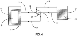
- the flow direction of the cooling medium 11 is as shown by the arrow in FIG. 4 , thereby implementing recovery of the cooling medium 11 in the cooling device 90. That is, the second operating mode of the diversion system 100 can be interpreted as recovering the cooling medium in the cooling device 90.
- the diversion system 100 further includes a first filter 41 provided in communication with the second pipeline 32 or the fourth pipeline 34.
- the first filter 41 can be mounted outside or inside the storage tank 10. Further, when the first filter 41 is disposed outside the storage tank 10, it may be mounted in the second pipeline 32 or the fourth pipeline 34. In the example shown in FIG. 5 , the first filter 41 is disposed inside the storage tank 10.
- the diversion system 100 further includes a third operating mode.
- the diversion system 100 can switch to the third operating mode.
- the second pipeline 32 and the fourth pipeline 34 are conducting, and the first pipeline 31 and the third pipeline 33 are closed.
- the pumping apparatus 20 extracts the cooling medium 11 from the storage tank 10 by means of the fourth pipeline 34, and then conveys the cooling medium 11 back to the storage tank 10 by means of the second pipeline 32.
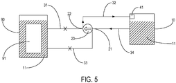
- the first filter 41 can filter the cooling medium 11 flowing therethrough, and the flow direction of the cooling medium 11 is as shown by the arrow in FIG. 5 , thereby implementing circulating filtration of the cooling medium 11 in the storage tank 10. That is, the third operating mode of the diversion system 100 can be interpreted as filtering the cooling medium 11 in the storage tank 10.
- the diversion system 100 further includes a second filter 42 provided in communication with the first pipeline 31 or the third pipeline 33.
- the second filter 42 can be mounted outside or inside the cooling device 90. Further, when the second filter 42 is disposed outside the cooling device 90, it may be mounted in the first pipeline 31 or the third pipeline 33. In the example shown in FIG. 6 , the second filter 42 is disposed inside the cooling device 90.
- the diversion system 100 further includes a fourth operating mode.
- the diversion system 100 can switch to the fourth operating mode.
- the first pipeline 31 and the third pipeline 33 are conducting, and the second pipeline 32 and the fourth pipeline 34 are closed.
- the pumping apparatus 20 extracts the cooling medium 11 from the cooling device 90 by means of the third pipeline 33, and then conveys the cooling medium 11 back to the cooling device 90 by means of the first pipeline 31.
- the second filter 42 can circulating-filter the cooling medium 11 flowing therethrough, and the flow direction of the cooling medium 11 is as shown by the arrow in FIG. 6 , thereby implementing filtration of the cooling medium 11 in the cooling device 90. That is, the fourth operating mode of the diversion system 100 can be interpreted as filtering the cooling medium 11 in the cooling device 90.
- the diversion system 100 further includes a controller for controlling the conducting or closing of the first pipeline 31, the second pipeline 32, the third pipeline 33, and the fourth pipeline 34, and a measuring meter for detecting the volume of the cooling medium 11 in the cooling device 90, the measuring meter in communicative connection to the controller.
- the valve may be a solenoid valve, and the controller can control opening or closing of the valves corresponding to the first pipeline 31, the second pipeline 32, the third pipeline 33, and the fourth pipeline 34, so as to implement the conducting or closing of the first pipeline 31, the second pipeline 32, the third pipeline 33, and the fourth pipeline 34.
- the controller controls the valves corresponding to the first pipeline 31 and the fourth pipeline 34 to open such that the first pipeline 31 and the fourth pipeline 34 are conducting, and controls the valves corresponding to the second pipeline 32 and the third pipeline 33 to close such that the second pipeline 32 and the third pipeline 33 are closed, thereby switching the diversion system 100 to the first operating mode and implementing replenishment of the cooling medium 11 in the cooling device 90.
- the controller controls the valves corresponding to the second pipeline 32 and the third pipeline 33 to open such that the second pipeline 32 and the third pipeline 33 are conducting, and controls the valves corresponding to the first pipeline 31 and the fourth pipeline 34 to close such that the first pipeline 31 and the fourth pipeline 34 are closed, thereby switching the diversion system 100 to the second operating mode and implementing recovery of the cooling medium 11 in the cooling device 90.
- the second volume is greater than the first volume.
- the first volume can be interpreted as the minimum volume allowed for the cooling medium 11 in the cooling device 90.
- the second volume can be interpreted as the maximum volume allowed for the cooling medium 11 in the cooling device 90.
- the diversion system 100 further includes a first detector for detecting purity of the cooling medium 11 in the storage tank 10, the first detector in communicative connection to the controller and capable of being mounted in the storage tank 10.
- the controller controls the valves corresponding to the second pipeline 32 and the fourth pipeline 34 to open such that the second pipeline 32 and the fourth pipeline 34 are conducting, and controls the valves corresponding to the first pipeline 31 and the third pipeline 33 to close such that the first pipeline 31 and the third pipeline 33 are closed, thereby switching the diversion system 100 to the third operating mode and implementing filtration of the cooling medium 11 in the storage tank 10.
- the diversion system 100 further includes a second detector for detecting the purity of the cooling medium 11 in the cooling device 90, the second detector in communicative connection to the controller and capable of being mounted in the cooling device 90.
- the controller controls the valves corresponding to the first pipeline 31 and the third pipeline 33 to open such that the first pipeline 31 and the third pipeline 33 are conducting, and controls the valves corresponding to the second pipeline 32 and the fourth pipeline 34 to close such that the second pipeline 32 and the fourth pipeline 34 are closed, thereby switching the diversion system 100 to the fourth operating mode and implementing filtration of the cooling medium 11 in the cooling device 90.
- the functions of automatic cooling medium replenishment and recovery for the cooling device 90 can be implemented by configuring the controller and the measuring meter.
- the function of automatic cooling medium filtration for the storage tank 10 and the cooling device 90 can be implemented by configuring the first detector and the second detector.
- first pipeline 31 and the second pipeline 32 can be connected to a first common pipeline 61 by means of a three-way connector 50, and both the first pipeline 31 and the second pipeline 32 are connected to the outlet 22 of the pumping apparatus 20 by means of the first common pipeline 61.
- the third pipeline 33 and the fourth pipeline 34 are connected to a second common pipeline 62 by means of a three-way connector 50, and both the third pipeline 33 and the fourth pipeline 34 are connected to the inlet 21 of the pumping apparatus 20 by means of the second common pipeline 62.
- the first common pipeline 61 can be shared by the first pipeline 31 and the second pipeline 32, and the second common pipeline 62 can be shared by the third pipeline 33 and the fourth pipeline 34.
- the pumping apparatus 20 only needs to be provided with one inlet 21 and one outlet 22, and only needs to be connected to the two pipelines of the first common pipeline 61 and the second common pipeline 62, thereby simplifying the device structure and reducing the cost.
- the first pipeline 31 and the third pipeline 33 can be connected to a third common pipeline 63 by means of a three-way connector 50, and both the first pipeline 31 and the third pipeline 33 are connected to the cooling device 90 by means of the third common pipeline 63.
- the cooling device 90 only needs to be provided with one connection port for connecting to the third common pipeline 63, thereby saving perforation costs.
- the third pipeline 33 and the fourth pipeline 34 can be connected to a fourth common pipeline 64 by means of a three-way connector 50, and both the third pipeline 33 and the fourth pipeline 34 are connected to the storage tank 10 by means of the fourth common pipeline 64.
- the storage tank 10 only needs to be provided with one connection port for connecting to the fourth common pipeline 64, thereby saving perforation costs.
- the number and arrangement of the three-way connectors and the common pipelines can be appropriately changed according to actual needs, which are not limited in the present application.
- one of the first pipeline 31 or the second pipeline 32 is configured to be conducting, and one of the third pipeline 33 or the fourth pipeline 34 is configured to be conducting, thereby forming a plurality of circulation paths of different flow directions for the cooling medium 11 to circulate, in which case only one pumping apparatus 20 is required for achieving various functions such as cooling medium replenishment for the cooling device 90, cooling medium recovery for the cooling device 90, filtration of the cooling medium 11 in the cooling device 90, and filtration of the cooling medium 11 in the storage tank 10, greatly reducing maintenance costs of the cooling device 90 and improving maintenance efficiency.
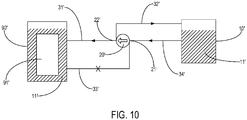
- the embodiments of the present application further provide a diversion system applicable to a cooling device, including: a storage tank 10' and a pumping apparatus 20', the storage tank 10' used for storing a cooling medium 11', and the pumping apparatus 20' including an inlet 21' and an outlet 22'.
- a first pipeline 31' is connected between the cooling device 90' and the outlet 22' of the pumping apparatus 20'
- a second pipeline 32' is connected between the storage tank 10' and the outlet 22' of the pumping apparatus 20'
- a third pipeline 33' is connected between the cooling device 90' and the inlet 21' of the pumping apparatus 20'
- a fourth pipeline 34' is connected between the storage tank 10' and the inlet 21' of the pumping apparatus 20'
- the first pipeline 31', the second pipeline 32', the third pipeline 33', and the fourth pipeline 34' can all selectively be conducting or be closed.
- the pumping apparatus 20' can convey the cooling medium 11' in the storage tank 10' into the cooling device 90' by means of the first pipeline 31' and the fourth pipeline 34', so as to implement cooling medium replenishment for the cooling device 90'.
- the pumping apparatus 20' can also circulate and convey the cooling medium 11' in the storage tank 10' back into the storage tank 10' by means of the second pipeline 32' and the fourth pipeline 34', and a filtration apparatus may be disposed in any one of the second pipeline 32' and the fourth pipeline 34', so as to implement filtration of the cooling medium 1 1' in the storage tank 10'.
- the pumping apparatus 20' can convey the cooling medium 11' in the cooling device 90' into the storage tank 10' by means of the second pipeline 32' and the third pipeline 33', so as to implement cooling medium recovery for the cooling device 90'.
- the pumping apparatus 20' can also circulating-convey the cooling medium 11' in the cooling device 90' back into the cooling device 90' by means of the first pipeline 31' and the third pipeline 33', and a filtration apparatus may be disposed in either of the first pipeline 31' and the third pipeline 33', so as to implement filtration of the cooling medium 11' in the cooling device 90'.
- the first pipeline 31', the second pipeline 32', the third pipeline 33', and the fourth pipeline 34' can form a plurality of circulation paths of different flow directions for the cooling medium 1 1' to circulate, in which case only one pumping apparatus 20' is required for achieving both conveying of the cooling medium 11' in the storage tank 10' into the cooling device 90' for replenishment and conveying of the cooling medium 11' in the cooling device 90' into the storage tank 10' for recovery, as well as filtration of the cooling medium 11' in the storage tank 10' and the cooling device 90', so that the diversion system has various functions, greatly reduces device maintenance costs, and improves maintenance efficiency.
- the embodiments of the present application further provide a cooling system, wherein the cooling system includes a first storage tank, a second storage tank, and a pumping apparatus, the first storage tank and the second storage tank are used for storing a cooling medium, the first storage tank is in communication with the second storage tank by means of the pumping apparatus, and the cooling system is configured to operate in a first mode and a second mode.
- the cooling system is in the first mode, the cooling medium in the first storage tank is introduced into the second storage tank by means of the pumping apparatus.
- the cooling system is in the second mode, the cooling medium in the second storage tank is introduced into the first storage tank by means of the pumping apparatus.
- directions of the cooling medium flowing through the pumping apparatus are the same.
- connection manner between the first storage tank, the second storage tank, and the pumping apparatus can be the same as a connection manner between the storage tank, the cooling device, and the pumping apparatus of the diversion system as described in the above embodiments and implementations.
Landscapes
- Engineering & Computer Science (AREA)
- Microelectronics & Electronic Packaging (AREA)
- Physics & Mathematics (AREA)
- Thermal Sciences (AREA)
- Computer Hardware Design (AREA)
- General Engineering & Computer Science (AREA)
- Chemical & Material Sciences (AREA)
- Chemical Kinetics & Catalysis (AREA)
- Cooling Or The Like Of Electrical Apparatus (AREA)
Abstract
Description
- The present application claims priority to Chinese Patent Application No.
201810107239.7, filed on February 02, 2018 - The present application relates to the technical field of cooling devices, and in particular to a diversion system and a cooling system applicable to a cooling device.
- With the rapid development of cloud computing technology (i.e., large-scale distributed system technology), the requirements for computing performance of servers have become increasingly high. When the performance of servers improves, the power consumption rapidly increases, and the power consumption of cabinets increases in multiples. The data shows that in the recent decade, the power density of data center cabinets has increased by nearly 15 times. In the past, the power consumption of a cabinet was generally 1.5 kW to 2 kW, but now, some cabinets have local power consumption reaching 20 kW to 30 kW.
- Cooling devices commonly used in data centers are filled with cooling media. A server that needs to be cooled is placed in the cooling device, and the server is cooled by means of the cooling media. During use, according to actual needs, the cooling device is replenished with cooling media or redundant cooling media in the cooling device are recovered. Generally, two pipelines are required to complete the cooling medium replenishment and cooling medium recovery.
- The purpose of the present application is to provide a diversion system and a cooling system applicable to a cooling device, so that replenishment and recovery of a cooling medium in the cooling device can be implemented by means of only one pumping apparatus.
- A first aspect of the embodiments of the present application provides a diversion system applicable to a cooling device, the system comprising: a storage tank and a pumping apparatus, the storage tank used for storing a cooling medium, and the pumping apparatus comprising an inlet and an outlet.
- A first pipeline is connected between the cooling device and the outlet of the pumping apparatus, a second pipeline is connected between the storage tank and the outlet of the pumping apparatus, a third pipeline is connected between the cooling device and the inlet of the pumping apparatus, a fourth pipeline is connected between the storage tank and the inlet of the pumping apparatus, and the first pipeline, the second pipeline, the third pipeline, and the fourth pipeline can all selectively be conducting or be closed.
- When the diversion system is operating, one of the first or the second pipelines is conducting, and one of the third or the fourth pipelines is conducting; and the pumping apparatus extracts the cooling medium by means of one of the third or the fourth pipelines that is conducting, and then conveys the cooling medium externally by means of one of the first or the second pipelines that is conducting.
- Further, the diversion system comprises a first operating mode and a second operating mode.
- When the diversion system is in the first operating mode, the first pipeline and the fourth pipeline are conducting, and the second pipeline and the third pipeline are closed; and the pumping apparatus extracts the cooling medium from the storage tank by means of the fourth pipeline, and then conveys the cooling medium into the cooling device by means of the first pipeline.
- When the diversion system is in the second operating mode, the second pipeline and the third pipeline are conducting, and the first pipeline and the fourth pipeline are closed; and the pumping apparatus extracts the cooling medium from the cooling device by means of the third pipeline, and then conveys the cooling medium into the storage tank by means of the second pipeline.
- The diversion system further includes a controller for controlling conducting or closing of the first pipeline, the second pipeline, the third pipeline, and the fourth pipeline, and a measuring meter for detecting a volume of the cooling medium in the cooling device, the measuring meter in communicative connection to the controller.
- When the measuring meter detects the volume of the cooling medium in the cooling device is less than a first volume, the controller controls the first pipeline and the fourth pipeline to be conducting and the second pipeline and the third pipeline to be closed, so as to switch the diversion system to the first operating mode.
- When the measuring meter detects the volume of the cooling medium in the cooling device exceeds a second volume, the controller controls the second pipeline and the third pipeline to be conducting and the first pipeline and the fourth pipeline to be closed, so as to switch the diversion system to the second operating mode, wherein the second volume is greater than the first volume.
- The diversion system further comprises a first filter provided in communication with the second pipeline or the fourth pipeline.
- The diversion system includes a third operating mode, wherein when the diversion system is in the third operating mode, the second pipeline and the fourth pipeline are conducting, and the first pipeline and the third pipeline are closed; the pumping apparatus extracts the cooling medium from the storage tank by means of the fourth pipeline, and then conveys the cooling medium back to the storage tank by means of the second pipeline; and the first filter filters the cooling medium flowing therethrough.
- Further, the first filter is disposed in the storage tank.
- The diversion system further comprises a controller for controlling conducting or closing of the first pipeline, the second pipeline, the third pipeline, and the fourth pipeline, and a first detector for detecting purity of the cooling medium in the storage tank, the first detector in communicative connection to the controller.
- When the first detector detects the purity of the cooling medium in the storage tank is less than a preset value, the controller controls the second pipeline and the fourth pipeline to be conducting and the first pipeline and the third pipeline to be closed, so as to switch the diversion system to the third operating mode.
- The diversion system further comprises a second filter provided in communication with the first pipeline or the third pipeline.
- The diversion system comprises a fourth operating mode, wherein when the diversion system is in the fourth operating mode, the first pipeline and the third pipeline are conducting, and the second pipeline and the fourth pipeline are closed; the pumping apparatus extracts the cooling medium from the cooling device by means of the third pipeline, and then conveys the cooling medium back to the cooling device by means of the first pipeline; and the second filter filters the cooling medium flowing therethrough.
- The diversion system further comprises a controller for controlling conducting or closing of the first pipeline, the second pipeline, the third pipeline, and the fourth pipeline, and a second detector for detecting purity of the cooling medium in the cooling device, the second detector in communicative connection to the controller.
- When the second detector detects the purity of the cooling medium in the cooling device is less than a preset value, the controller controls the first pipeline and the third pipeline to be conducting and the second pipeline and the fourth pipeline to be closed, so as to switch the diversion system to the fourth operating mode.
- Further, the first pipeline, the second pipeline, the third pipeline, and the fourth pipeline are all provided with a valve; and the valve can be opened or closed so that a corresponding pipeline in the first pipeline, the second pipeline, the third pipeline, and the fourth pipeline can be conducting or closed.
- Further, the first pipeline and the second pipeline are connected to a first common pipeline by means of a three-way connector, and both the first pipeline and the second pipeline are connected to the outlet of the pumping apparatus by means of the first common pipeline.
- Further, the third pipeline and the fourth pipeline are connected to a second common pipeline by means of a three-way connector, and both the third pipeline and the fourth pipeline are connected to the inlet of the pumping apparatus by means of the second common pipeline.
- Further, the first pipeline and the third pipeline are connected to a third common pipeline by means of a three-way connector, and both the first pipeline and the third pipeline are connected to the cooling device by means of the third common pipeline.
- A second aspect of the embodiments of the present application provides a diversion system applicable to a cooling device, the system comprising: a storage tank and a pumping apparatus, the storage tank used for storing a cooling medium, and the pumping apparatus comprising an inlet and an outlet.
- A first pipeline is connected between the cooling device and the outlet of the pumping apparatus, a second pipeline is connected between the storage tank and the outlet of the pumping apparatus, a third pipeline is connected between the cooling device and the inlet of the pumping apparatus, a fourth pipeline is connected between the storage tank and the inlet of the pumping apparatus, and the first pipeline, the second pipeline, the third pipeline, and the fourth pipeline can all selectively be conducting or be closed.
- When the diversion system is operating, at least two of the first pipeline, the second pipeline, the third pipeline, and the fourth pipeline are conducting.
- A third aspect of the embodiments of the present application provides a cooling system, wherein the cooling system comprises a first storage tank, a second storage tank, and a pumping apparatus, the first storage tank and the second storage tank are used for storing a cooling medium, the first storage tank is in communication with the second storage tank by means of the pumping apparatus, and the cooling system is configured to operate in a first mode and a second mode.
- In the first mode, the cooling medium in the first storage tank is introduced into the second storage tank by means of the pumping apparatus; in the second mode, the cooling medium in the second storage tank is introduced into the first storage tank by means of the pumping apparatus; and in the first mode and the second mode, directions of the cooling medium flowing through the pumping apparatus are the same.
- As can be seen from the above technical solutions, in the diversion system of the present application, one of the first or the second pipelines is conducting, and one of the third or the fourth pipelines is conducting, thereby forming a plurality of circulation paths of different flow directions for the cooling medium to circulate, in which case only one pumping apparatus is required for achieving both conveying of the cooling medium in the cooling device into the storage tank for recovery and conveying of the cooling medium in the storage tank into the cooling device for replenishment, so that the diversion system has various functions, greatly reduces maintenance costs of the cooling device, and improves maintenance efficiency.
-
-
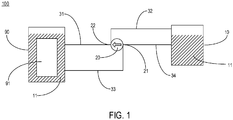
FIG. 1 illustrates a schematic structural diagram of a diversion system according to an exemplary embodiment of the present application; -
FIG. 2 illustrates another schematic structural diagram of the diversion system according to an exemplary embodiment of the present application; -
FIG. 3 illustrates a schematic structural diagram of the diversion system in a first operating mode according to an exemplary embodiment of the present application; -
FIG. 4 illustrates a schematic structural diagram of the diversion system in a second operating mode according to an exemplary embodiment of the present application; -
FIG. 5 illustrates a schematic structural diagram of the diversion system in a third operating mode according to an exemplary embodiment of the present application; -
FIG. 6 illustrates a schematic structural diagram of the diversion system in a fourth operating mode according to an exemplary embodiment of the present application; -
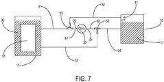
FIG. 7 illustrates yet another schematic structural diagram of the diversion system according to an exemplary embodiment of the present application; -
FIG. 8 illustrates yet another schematic structural diagram of the diversion system according to an exemplary embodiment of the present application; -
FIG. 9 illustrates yet another schematic structural diagram of the diversion system according to an exemplary embodiment of the present application; -
FIG. 10 illustrates yet another schematic structural diagram of the diversion system according to an exemplary embodiment of the present application; and -
FIG. 11 illustrates yet another schematic structural diagram of the diversion system according to an exemplary embodiment of the present application. - The exemplary embodiments will be described in detail herein, examples of which are shown in the drawings. The following description relates to the drawings, unless otherwise indicated, the same number in different drawings represents the same or similar element. The implementations described in the following exemplary embodiments do not represent all the implementations consistent with the present application. Rather, they are merely examples of devices and methods consistent with some aspects of the present application, as detailed in the appended claims.
- The terminologies used in the present application are for the purpose of describing particular embodiments only and are not intended to limit the present application. As used in the present application and in the appended claims, the singular forms "a/an", "said", and "the" are also intended to include the case of plural forms, unless the context clearly indicates other meanings. It should also be understood that the term "and/or" used herein refers to and includes any or all possible combinations of one or a plurality of associated listed items.
- It should be understood that although terms first, second, third, etc. may be used to describe various kinds of information. These kinds of information should not be limited to these terms. These terms are used only to distinguish one piece of information from one another of the same type. For example, without departing from the scope of the present application, first information may also be referred to as second information, and similarly, second information may also be referred to as first information. Depending on the context, the word "if' as used herein can be interpreted as "at the time" or "when" or "in response to the determination".
- The purpose of the present application is to provide a diversion system applicable to a cooling device, so that replenishment and recovery of a cooling medium in the cooling device can be implemented by means of only one pumping apparatus. The cooling device of the present application is described in detail below with reference to the drawings. When no conflicts exist, the features of the following embodiments and implementations can be combined with each other.
- Please refer to
FIG. 1 . The embodiments of the present application provide adiversion system 100 applicable to a cooling device. Thediversion system 100 includes: astorage tank 10 and apumping apparatus 20, the storage tank used for storing a coolingmedium 11, and thepumping apparatus 20 including aninlet 21 and anoutlet 22. Optionally, a pump may be adopted as thepumping apparatus 20. - The
cooling device 90 may be filled with the coolingmedium 11, a to-be-cooled apparatus 91 is at least partially immersed in the coolingmedium 11, and heat dissipation is performed for the to-be-cooled apparatus 91 by means of the coolingmedium 11. The to-be-cooled apparatus 91 may be a server of a data center, or may be other heat-producing devices that need to be cooled. The cooling medium 80 may be a gaseous medium, a liquid medium, or a solid-liquid mixed medium capable of being configured according to actual needs. In the example shown by the present application, the to-be-cooled apparatus 91 is completely immersed in the coolingmedium 11, and the coolingmedium 11 is an electronic fluorinated liquid. - A
first pipeline 31 is connected between the coolingdevice 90 and theoutlet 22 of thepumping apparatus 20, asecond pipeline 32 is connected between thestorage tank 10 and theoutlet 22 of thepumping apparatus 20, athird pipeline 33 is connected between the coolingdevice 90 and theinlet 21 of thepumping apparatus 20, afourth pipeline 34 is connected between thestorage tank 10 and theinlet 21 of thepumping apparatus 20, and thefirst pipeline 31, thesecond pipeline 32, thethird pipeline 33, and thefourth pipeline 34 can all selectively be conducting or be closed. - It can be understood that the
pumping apparatus 20 may be provided with twooutlets 22 connected to thefirst pipeline 31 and thesecond pipeline 32 in a one-to-one correspondence. Thepumping apparatus 20 may be provided with twoinlets 21 connected to thethird pipeline 33 and thefourth pipeline 34 in a one-to-one correspondence. Similarly, thestorage tank 10 and thecooling device 90 may be respectively provided with two connection ports for connecting to the correspondingfirst pipeline 31,second pipeline 32,third pipeline 33, andfourth pipeline 34. - When the
diversion system 100 is operating, one of thefirst pipeline 31 or thesecond pipeline 32 is conducting, and one of thethird pipeline 33 or thefourth pipeline 34 is conducting. Thepumping apparatus 20 extracts the coolingmedium 11 by means of thethird pipeline 33 or thefourth pipeline 34 that is conducting, and then conveys the coolingmedium 11 externally by means of thefirst pipeline 31 or thesecond pipeline 32 that is conducting. - As can be seen from the above technical solutions, in the
diversion system 100 of the present application, one of thefirst pipeline 31 or thesecond pipeline 32 is conducting, and one of thethird pipeline 33 or thefourth pipeline 34 is conducting, thereby forming a plurality of circulation paths of different flow directions for the coolingmedium 11 to circulate, in which case only onepumping apparatus 20 is required for achieving both conveying of the coolingmedium 11 in thecooling device 90 into thestorage tank 10 for recovery and conveying of the coolingmedium 11 in thestorage tank 10 into thecooling device 90 for replenishment, so that thediversion system 100 has various functions, greatly reduces maintenance costs of thecooling device 90, and improves maintenance efficiency. - Referring to
FIG. 2 , in an optional implementation, thefirst pipeline 31, thesecond pipeline 32, thethird pipeline 33, and thefourth pipeline 34 are all provided with a valve; and conducting or closing of thefirst pipeline 31, thesecond pipeline 32, thethird pipeline 33, and thefourth pipeline 34 is implemented by opening or closing a corresponding valve. It can be understood that in the example shown inFIG. 2 , thefirst pipeline 31 is provided with afirst valve 401, thesecond pipeline 32 is provided with asecond valve 402, thethird pipeline 33 is provided athird valve 403, thefourth pipeline 34 is provided with afourth valve 404. The conducting or closing of thefirst pipeline 31 is implemented by opening or closing thefirst valve 401. The conducting or closing of thesecond pipeline 32 is implemented by opening or closing thesecond valve 402. The conducting or closing of thethird pipeline 33 is implemented by opening or closing thethird valve 403. The conducting or closing of thefourth pipeline 34 is implemented by opening or closing thefourth valve 404. Certainly, the conducting or closing of thefirst pipeline 31, thesecond pipeline 32, thethird pipeline 33, and thefourth pipeline 34 can also be implemented in other manners, which are not limited to the manner of valves described in the present application. - In an optional implementation, the
diversion system 100 includes a first operating mode and a second operating mode. - Referring to
FIG. 3 , when the volume of the coolingmedium 11 in thecooling device 90 is insufficient to satisfy the requirements of heat dissipation, thediversion system 100 may switch to the first operating mode. When thediversion system 100 is in the first operating mode, thefirst pipeline 31 and thefourth pipeline 34 are conducting, and thesecond pipeline 32 and thethird pipeline 33 are closed. Thepumping apparatus 20 extracts the cooling medium 11 from thestorage tank 10 by means of thefourth pipeline 34, and then conveys the coolingmedium 11 into thecooling device 90 by means of thefirst pipeline 31. The flow direction of the coolingmedium 11 is as shown by the arrow inFIG. 3 , thereby implementing replenishment of the coolingmedium 11 in thecooling device 90. That is, the first operating mode of thediversion system 100 can be interpreted as replenishing thecooling device 90 with the cooling medium. - Please refer to
FIG. 4 . When the volume of the coolingmedium 11 in thecooling device 90 is excessive and overflowing may occur, thediversion system 100 may switch to the second operating mode. When thediversion system 100 is in the second operating mode, thesecond pipeline 32 and thethird pipeline 33 are conducting, and thefirst pipeline 31 and thefourth pipeline 34 are closed. Thepumping apparatus 20 extracts the cooling medium 11 from the coolingdevice 90 by means of thethird pipeline 33, and then conveys the coolingmedium 11 into thestorage tank 10 by means of thesecond pipeline 32. The flow direction of the coolingmedium 11 is as shown by the arrow inFIG. 4 , thereby implementing recovery of the coolingmedium 11 in thecooling device 90. That is, the second operating mode of thediversion system 100 can be interpreted as recovering the cooling medium in thecooling device 90. - Please refer to
FIG. 5 . In an optional implementation, thediversion system 100 further includes afirst filter 41 provided in communication with thesecond pipeline 32 or thefourth pipeline 34. Thefirst filter 41 can be mounted outside or inside thestorage tank 10. Further, when thefirst filter 41 is disposed outside thestorage tank 10, it may be mounted in thesecond pipeline 32 or thefourth pipeline 34. In the example shown inFIG. 5 , thefirst filter 41 is disposed inside thestorage tank 10. - The
diversion system 100 further includes a third operating mode. When purity of the coolingmedium 11 in thestorage tank 10 cannot satisfy the requirements, thediversion system 100 can switch to the third operating mode. When thediversion system 100 is in the third operating mode, thesecond pipeline 32 and thefourth pipeline 34 are conducting, and thefirst pipeline 31 and thethird pipeline 33 are closed. Thepumping apparatus 20 extracts the cooling medium 11 from thestorage tank 10 by means of thefourth pipeline 34, and then conveys the coolingmedium 11 back to thestorage tank 10 by means of thesecond pipeline 32. Thefirst filter 41 can filter the coolingmedium 11 flowing therethrough, and the flow direction of the coolingmedium 11 is as shown by the arrow inFIG. 5 , thereby implementing circulating filtration of the coolingmedium 11 in thestorage tank 10. That is, the third operating mode of thediversion system 100 can be interpreted as filtering the coolingmedium 11 in thestorage tank 10. - Please refer to
FIG. 6 . In an optional implementation, thediversion system 100 further includes asecond filter 42 provided in communication with thefirst pipeline 31 or thethird pipeline 33. Thesecond filter 42 can be mounted outside or inside the coolingdevice 90. Further, when thesecond filter 42 is disposed outside thecooling device 90, it may be mounted in thefirst pipeline 31 or thethird pipeline 33. In the example shown inFIG. 6 , thesecond filter 42 is disposed inside the coolingdevice 90. - The
diversion system 100 further includes a fourth operating mode. When purity of the coolingmedium 11 in thecooling device 90 cannot satisfy the requirements, thediversion system 100 can switch to the fourth operating mode. When thediversion system 100 is in the fourth operating mode, thefirst pipeline 31 and thethird pipeline 33 are conducting, and thesecond pipeline 32 and thefourth pipeline 34 are closed. Thepumping apparatus 20 extracts the cooling medium 11 from the coolingdevice 90 by means of thethird pipeline 33, and then conveys the coolingmedium 11 back to thecooling device 90 by means of thefirst pipeline 31. Thesecond filter 42 can circulating-filter the coolingmedium 11 flowing therethrough, and the flow direction of the coolingmedium 11 is as shown by the arrow inFIG. 6 , thereby implementing filtration of the coolingmedium 11 in thecooling device 90. That is, the fourth operating mode of thediversion system 100 can be interpreted as filtering the coolingmedium 11 in thecooling device 90. - In an optional implementation, the
diversion system 100 further includes a controller for controlling the conducting or closing of thefirst pipeline 31, thesecond pipeline 32, thethird pipeline 33, and thefourth pipeline 34, and a measuring meter for detecting the volume of the coolingmedium 11 in thecooling device 90, the measuring meter in communicative connection to the controller. It can be understood that the valve may be a solenoid valve, and the controller can control opening or closing of the valves corresponding to thefirst pipeline 31, thesecond pipeline 32, thethird pipeline 33, and thefourth pipeline 34, so as to implement the conducting or closing of thefirst pipeline 31, thesecond pipeline 32, thethird pipeline 33, and thefourth pipeline 34. - When the measuring meter detects the volume of the cooling
medium 11 in thecooling device 90 is less than a first volume, the controller controls the valves corresponding to thefirst pipeline 31 and thefourth pipeline 34 to open such that thefirst pipeline 31 and thefourth pipeline 34 are conducting, and controls the valves corresponding to thesecond pipeline 32 and thethird pipeline 33 to close such that thesecond pipeline 32 and thethird pipeline 33 are closed, thereby switching thediversion system 100 to the first operating mode and implementing replenishment of the coolingmedium 11 in thecooling device 90. - When the measuring meter detects the volume of the cooling
medium 11 in thecooling device 90 exceeds a second volume, the controller controls the valves corresponding to thesecond pipeline 32 and thethird pipeline 33 to open such that thesecond pipeline 32 and thethird pipeline 33 are conducting, and controls the valves corresponding to thefirst pipeline 31 and thefourth pipeline 34 to close such that thefirst pipeline 31 and thefourth pipeline 34 are closed, thereby switching thediversion system 100 to the second operating mode and implementing recovery of the coolingmedium 11 in thecooling device 90. The second volume is greater than the first volume. The first volume can be interpreted as the minimum volume allowed for the coolingmedium 11 in thecooling device 90. The second volume can be interpreted as the maximum volume allowed for the coolingmedium 11 in thecooling device 90. - In an optional implementation, the
diversion system 100 further includes a first detector for detecting purity of the coolingmedium 11 in thestorage tank 10, the first detector in communicative connection to the controller and capable of being mounted in thestorage tank 10. - When the first detector detects the purity of the cooling
medium 11 in thestorage tank 10 is less than a preset value, the controller controls the valves corresponding to thesecond pipeline 32 and thefourth pipeline 34 to open such that thesecond pipeline 32 and thefourth pipeline 34 are conducting, and controls the valves corresponding to thefirst pipeline 31 and thethird pipeline 33 to close such that thefirst pipeline 31 and thethird pipeline 33 are closed, thereby switching thediversion system 100 to the third operating mode and implementing filtration of the coolingmedium 11 in thestorage tank 10. - In an optional implementation, the
diversion system 100 further includes a second detector for detecting the purity of the coolingmedium 11 in thecooling device 90, the second detector in communicative connection to the controller and capable of being mounted in thecooling device 90. - When the second detector detects the purity of the cooling
medium 11 in thecooling device 90 is less than a preset value, the controller controls the valves corresponding to thefirst pipeline 31 and thethird pipeline 33 to open such that thefirst pipeline 31 and thethird pipeline 33 are conducting, and controls the valves corresponding to thesecond pipeline 32 and thefourth pipeline 34 to close such that thesecond pipeline 32 and thefourth pipeline 34 are closed, thereby switching thediversion system 100 to the fourth operating mode and implementing filtration of the coolingmedium 11 in thecooling device 90. - Therefore, the functions of automatic cooling medium replenishment and recovery for the
cooling device 90 can be implemented by configuring the controller and the measuring meter. The function of automatic cooling medium filtration for thestorage tank 10 and thecooling device 90 can be implemented by configuring the first detector and the second detector. - Please refer to
FIG. 7 . In an optional implementation, thefirst pipeline 31 and thesecond pipeline 32 can be connected to a firstcommon pipeline 61 by means of a three-way connector 50, and both thefirst pipeline 31 and thesecond pipeline 32 are connected to theoutlet 22 of thepumping apparatus 20 by means of the firstcommon pipeline 61. Thethird pipeline 33 and thefourth pipeline 34 are connected to a secondcommon pipeline 62 by means of a three-way connector 50, and both thethird pipeline 33 and thefourth pipeline 34 are connected to theinlet 21 of thepumping apparatus 20 by means of the secondcommon pipeline 62. Through the configuration of the three-way connector 50, the firstcommon pipeline 61 can be shared by thefirst pipeline 31 and thesecond pipeline 32, and the secondcommon pipeline 62 can be shared by thethird pipeline 33 and thefourth pipeline 34. In this way, thepumping apparatus 20 only needs to be provided with oneinlet 21 and oneoutlet 22, and only needs to be connected to the two pipelines of the firstcommon pipeline 61 and the secondcommon pipeline 62, thereby simplifying the device structure and reducing the cost. - Please refer to
FIG. 8 . Without considering the function of filtering the coolingmedium 11 in thecooling device 90, thefirst pipeline 31 and thethird pipeline 33 can be connected to a thirdcommon pipeline 63 by means of a three-way connector 50, and both thefirst pipeline 31 and thethird pipeline 33 are connected to thecooling device 90 by means of the thirdcommon pipeline 63. In this way, thecooling device 90 only needs to be provided with one connection port for connecting to the thirdcommon pipeline 63, thereby saving perforation costs. - Further, referring to
FIG. 9 , without considering the function of filtering the coolingmedium 11 in thestorage tank 10, thethird pipeline 33 and thefourth pipeline 34 can be connected to a fourthcommon pipeline 64 by means of a three-way connector 50, and both thethird pipeline 33 and thefourth pipeline 34 are connected to thestorage tank 10 by means of the fourthcommon pipeline 64. In this way, thestorage tank 10 only needs to be provided with one connection port for connecting to the fourthcommon pipeline 64, thereby saving perforation costs. Certainly, the number and arrangement of the three-way connectors and the common pipelines can be appropriately changed according to actual needs, which are not limited in the present application. - In conclusion, in the
diversion system 100 of the present application, one of thefirst pipeline 31 or thesecond pipeline 32 is configured to be conducting, and one of thethird pipeline 33 or thefourth pipeline 34 is configured to be conducting, thereby forming a plurality of circulation paths of different flow directions for the coolingmedium 11 to circulate, in which case only onepumping apparatus 20 is required for achieving various functions such as cooling medium replenishment for thecooling device 90, cooling medium recovery for thecooling device 90, filtration of the coolingmedium 11 in thecooling device 90, and filtration of the coolingmedium 11 in thestorage tank 10, greatly reducing maintenance costs of thecooling device 90 and improving maintenance efficiency. - Please refer to
FIGS. 9 and10 . The embodiments of the present application further provide a diversion system applicable to a cooling device, including: a storage tank 10' and a pumping apparatus 20', the storage tank 10' used for storing a cooling medium 11', and the pumping apparatus 20' including an inlet 21' and an outlet 22'. A first pipeline 31' is connected between the cooling device 90' and the outlet 22' of the pumping apparatus 20', a second pipeline 32' is connected between the storage tank 10' and the outlet 22' of the pumping apparatus 20', a third pipeline 33' is connected between the cooling device 90' and the inlet 21' of the pumping apparatus 20', a fourth pipeline 34' is connected between the storage tank 10' and the inlet 21' of the pumping apparatus 20', and the first pipeline 31', the second pipeline 32', the third pipeline 33', and the fourth pipeline 34' can all selectively be conducting or be closed. When the diversion system is operating, at least two of the first pipeline 31', the second pipeline 32', the third pipeline 33', and the fourth pipeline 34' are conducting. - As shown in
FIG. 10 , when the first pipeline 31', the second pipeline 32', and the fourth pipeline 34' are conducting, the pumping apparatus 20' can convey the cooling medium 11' in the storage tank 10' into the cooling device 90' by means of the first pipeline 31' and the fourth pipeline 34', so as to implement cooling medium replenishment for the cooling device 90'. The pumping apparatus 20' can also circulate and convey the cooling medium 11' in the storage tank 10' back into the storage tank 10' by means of the second pipeline 32' and the fourth pipeline 34', and a filtration apparatus may be disposed in any one of the second pipeline 32' and the fourth pipeline 34', so as to implement filtration of the cooling medium 1 1' in the storage tank 10'. - As shown in
FIG. 11 , when the first pipeline 31', the second pipeline 32', and the third pipeline 33' are conducting, the pumping apparatus 20' can convey the cooling medium 11' in the cooling device 90' into the storage tank 10' by means of the second pipeline 32' and the third pipeline 33', so as to implement cooling medium recovery for the cooling device 90'. The pumping apparatus 20' can also circulating-convey the cooling medium 11' in the cooling device 90' back into the cooling device 90' by means of the first pipeline 31' and the third pipeline 33', and a filtration apparatus may be disposed in either of the first pipeline 31' and the third pipeline 33', so as to implement filtration of the cooling medium 11' in the cooling device 90'. - In the diversion system of the present application, the first pipeline 31', the second pipeline 32', the third pipeline 33', and the fourth pipeline 34' can form a plurality of circulation paths of different flow directions for the cooling medium 1 1' to circulate, in which case only one pumping apparatus 20' is required for achieving both conveying of the cooling medium 11' in the storage tank 10' into the cooling device 90' for replenishment and conveying of the cooling medium 11' in the cooling device 90' into the storage tank 10' for recovery, as well as filtration of the cooling medium 11' in the storage tank 10' and the cooling device 90', so that the diversion system has various functions, greatly reduces device maintenance costs, and improves maintenance efficiency.
- The embodiments of the present application further provide a cooling system, wherein the cooling system includes a first storage tank, a second storage tank, and a pumping apparatus, the first storage tank and the second storage tank are used for storing a cooling medium, the first storage tank is in communication with the second storage tank by means of the pumping apparatus, and the cooling system is configured to operate in a first mode and a second mode. When the cooling system is in the first mode, the cooling medium in the first storage tank is introduced into the second storage tank by means of the pumping apparatus. When the cooling system is in the second mode, the cooling medium in the second storage tank is introduced into the first storage tank by means of the pumping apparatus. In the first mode and the second mode, directions of the cooling medium flowing through the pumping apparatus are the same.
- In this way, only one pumping apparatus is required for implementing circulation of the cooling medium between the two storage tanks, without the need for an extra pumping apparatus, thereby greatly reducing device costs. It should be noted that a connection manner between the first storage tank, the second storage tank, and the pumping apparatus can be the same as a connection manner between the storage tank, the cooling device, and the pumping apparatus of the diversion system as described in the above embodiments and implementations.
- Other embodiments of the present application will be readily conceivable by those skilled in the art after considering the invention disclosed in the specification and practicing herein. The present application is intended to cover any variations, uses, or adaptations of the present application, and the variations, uses, or adaptations are governed by the general principles of the present application and include commonly known knowledge or conventional technical means in the art that are not disclosed in the present application. The specification and embodiments are considered illustrative only and the actual scope and spirit of the present application are indicated by the appended claims.
- It should further be noted that the term "include," "comprise," or any other variation thereof is intended to encompass a non-exclusive inclusion, so that a process, method, commodity, or device that includes a series of elements includes not only those elements but also other elements not explicitly listed, or elements that are inherent to such a process, method, commodity, or device. The element defined by the statement "including one ...," without further limitation, does not preclude the presence of additional identical elements in the process, method, commodity, or device that includes the element.
- The above description is merely a preferred embodiment of the present application and is not intended to limit the present application. Any modifications, equivalent substitutions, improvements, and etc. made within the spirit and principles of the present application should be included within the scope of protection of the present application.
Claims (14)
- A diversion system applicable to a cooling device, the system comprising: a storage tank and a pumping apparatus, the storage tank used for storing a cooling medium, and the pumping apparatus comprising an inlet and an outlet, wherein
a first pipeline is connected between the cooling device and the outlet of the pumping apparatus, a second pipeline is connected between the storage tank and the outlet of the pumping apparatus, a third pipeline is connected between the cooling device and the inlet of the pumping apparatus, a fourth pipeline is connected between the storage tank and the inlet of the pumping apparatus, and the first pipeline, the second pipeline, the third pipeline, and the fourth pipeline can all selectively be conducting or be closed; and
when the diversion system is operating, one of the first or the second pipelines is conducting, and one of the third or the fourth pipelines is conducting; and the pumping apparatus extracts the cooling medium by means of one of the third or the fourth pipelines that is conducting, and then conveys the cooling medium externally by means of one of the first or the second pipelines that is conducting. - The diversion system according to claim 1, wherein the diversion system comprises a first operating mode and a second operating mode;
when the diversion system is in the first operating mode, the first pipeline and the fourth pipeline are conducting, and the second pipeline and the third pipeline are closed; and the pumping apparatus extracts the cooling medium from the storage tank by means of the fourth pipeline, and then conveys the cooling medium into the cooling device by means of the first pipeline; and
when the diversion system is in the second operating mode, the second pipeline and the third pipeline are conducting, and the first pipeline and the fourth pipeline are closed; and the pumping apparatus extracts the cooling medium from the cooling device by means of the third pipeline, and then conveys the cooling medium into the storage tank by means of the second pipeline. - The diversion system according to claim 2, further comprising a controller for controlling conducting or closing of the first pipeline, the second pipeline, the third pipeline, and the fourth pipeline, and a measuring meter for detecting a volume of the cooling medium in the cooling device, the measuring meter in communicative connection to the controller;
when the measuring meter detects the volume of the cooling medium in the cooling device is less than a first volume, the controller controls the first pipeline and the fourth pipeline to be conducting and the second pipeline and the third pipeline to be closed, so as to switch the diversion system to the first operating mode.
when the measuring meter detects the volume of the cooling medium in the cooling device exceeds a second volume, the controller controls the second pipeline and the third pipeline to be conducting and the first pipeline and the fourth pipeline to be closed, so as to switch the diversion system to the second operating mode, wherein the second volume is greater than the first volume. - The diversion system according to claim 1, further comprising a first filter provided in communication with the second pipeline or the fourth pipeline; and
the diversion system comprising a third operating mode, wherein when the diversion system is in the third operating mode, the second pipeline and the fourth pipeline are conducting, and the first pipeline and the third pipeline are closed; the pumping apparatus extracts the cooling medium from the storage tank by means of the fourth pipeline, and then conveys the cooling medium back to the storage tank by means of the second pipeline; and the first filter filters the cooling medium flowing therethrough. - The diversion system according to claim 4, wherein the first filter is disposed in the storage tank.
- The diversion system according to claim 4, further comprising a controller for controlling conducting or closing of the first pipeline, the second pipeline, the third pipeline, and the fourth pipeline, and a first detector for detecting purity of the cooling medium in the storage tank, the first detector in communicative connection to the controller; and
when the first detector detects the purity of the cooling medium in the storage tank is less than a preset value, the controller controls the second pipeline and the fourth pipeline to be conducting and the first pipeline and the third pipeline to be closed, so as to switch the diversion system to the third operating mode. - The diversion system according to claim 1, further comprising a second filter provided in communication with the first pipeline or the third pipeline;
the diversion system comprising a fourth operating mode, wherein when the diversion system is in the fourth operating mode, the first pipeline and the third pipeline are conducting, and the second pipeline and the fourth pipeline are closed; the pumping apparatus extracts the cooling medium from the cooling device by means of the third pipeline, and then conveys the cooling medium back to the cooling device by means of the first pipeline; and the second filter filters the cooling medium flowing therethrough. - The diversion system according to claim 7, further comprising a controller for controlling conducting or closing of the first pipeline, the second pipeline, the third pipeline, and the fourth pipeline, and a second detector for detecting purity of the cooling medium in the cooling device, the second detector in communicative connection to the controller; and
when the second detector detects the purity of the cooling medium in the cooling device is less than a preset value, the controller controls the first pipeline and the third pipeline to be conducting and the second pipeline and the fourth pipeline to be closed, so as to switch the diversion system to the fourth operating mode. - The diversion system according to claim 1, wherein the first pipeline, the second pipeline, the third pipeline, and the fourth pipeline are all provided with a valve; and the valve can be opened or closed so that a corresponding pipeline in the first pipeline, the second pipeline, the third pipeline, and the fourth pipeline can be conducting or closed.
- The diversion system according to claim 1, wherein the first pipeline and the second pipeline are connected to a first common pipeline by means of a three-way connector, and both the first pipeline and the second pipeline are connected to the outlet of the pumping apparatus by means of the first common pipeline.
- The diversion system according to claim 1, wherein the third pipeline and the fourth pipeline are connected to a second common pipeline by means of a three-way connector, and both the third pipeline and the fourth pipeline are connected to the inlet of the pumping apparatus by means of the second common pipeline.
- The diversion system according to claim 1, wherein the first pipeline and the third pipeline are connected to a third common pipeline by means of a three-way connector, and both the first pipeline and the third pipeline are connected to the cooling device by means of the third common pipeline.
- A diversion system applicable to a cooling device, the system comprising: a storage tank and a pumping apparatus, the storage tank used for storing a cooling medium, and the pumping apparatus comprising an inlet and an outlet;
a first pipeline is connected between the cooling device and the outlet of the pumping apparatus, a second pipeline is connected between the storage tank and the outlet of the pumping apparatus, a third pipeline is connected between the cooling device and the inlet of the pumping apparatus, a fourth pipeline is connected between the storage tank and the inlet of the pumping apparatus, and the first pipeline, the second pipeline, the third pipeline, and the fourth pipeline can all selectively be conducting or be closed; and
when the diversion system is operating, at least two of the first pipeline, the second pipeline, the third pipeline, and the fourth pipeline are conducting. - A cooling system, wherein the cooling system comprises a first storage tank, a second storage tank, and a pumping apparatus, the first storage tank and the second storage tank are used for storing a cooling medium, the first storage tank is in communication with the second storage tank by means of the pumping apparatus, and the cooling system is configured to operate in a first mode and a second mode; and
in the first mode, the cooling medium in the first storage tank is introduced into the second storage tank by means of the pumping apparatus; in the second mode, the cooling medium in the second storage tank is introduced into the first storage tank by means of the pumping apparatus; and in the first mode and the second mode, directions of the cooling medium flowing through the pumping apparatus are the same.
Applications Claiming Priority (2)
| Application Number | Priority Date | Filing Date | Title |
|---|---|---|---|
| CN201810107239.7A CN110139531B (en) | 2018-02-02 | 2018-02-02 | Flow guide system suitable for cooling equipment and cooling system |
| PCT/CN2019/072675 WO2019149113A1 (en) | 2018-02-02 | 2019-01-22 | Diversion system for cooling apparatus and cooling system |
Publications (3)
| Publication Number | Publication Date |
|---|---|
| EP3749074A1 true EP3749074A1 (en) | 2020-12-09 |
| EP3749074A4 EP3749074A4 (en) | 2021-11-10 |
| EP3749074B1 EP3749074B1 (en) | 2024-09-04 |
Family
ID=67479145
Family Applications (1)
| Application Number | Title | Priority Date | Filing Date |
|---|---|---|---|
| EP19747364.8A Active EP3749074B1 (en) | 2018-02-02 | 2019-01-22 | Diversion system for cooling apparatus and cooling system |
Country Status (5)
| Country | Link |
|---|---|
| US (1) | US12016160B2 (en) |
| EP (1) | EP3749074B1 (en) |
| JP (1) | JP2021513157A (en) |
| CN (1) | CN110139531B (en) |
| WO (1) | WO2019149113A1 (en) |
Families Citing this family (2)
| Publication number | Priority date | Publication date | Assignee | Title |
|---|---|---|---|---|
| CN117704879A (en) * | 2022-09-07 | 2024-03-15 | 英业达科技有限公司 | Liquid level control device |
| CN117742394A (en) * | 2022-09-13 | 2024-03-22 | 英业达科技有限公司 | Liquid level control device |
Family Cites Families (32)
| Publication number | Priority date | Publication date | Assignee | Title |
|---|---|---|---|---|
| JP2748732B2 (en) * | 1991-07-19 | 1998-05-13 | 日本電気株式会社 | Liquid refrigerant circulation system |
| DE10027002B4 (en) | 1999-06-02 | 2005-02-17 | Advantest Corp. | cooling system |
| JP3987358B2 (en) * | 2002-03-18 | 2007-10-10 | ダイダン株式会社 | Flow control system with split flow measurement |
| GB0207382D0 (en) | 2002-03-28 | 2002-05-08 | Holland Heating Uk Ltd | Computer cabinet |
| US6859366B2 (en) | 2003-03-19 | 2005-02-22 | American Power Conversion | Data center cooling system |
| US7046514B2 (en) | 2003-03-19 | 2006-05-16 | American Power Conversion Corporation | Data center cooling |
| TWI248863B (en) * | 2004-02-12 | 2006-02-11 | Mitsubishi Heavy Ind Ltd | Apparatus and method for mold temperature adjustment, and mold temperature control unit |
| US8009430B2 (en) | 2007-05-17 | 2011-08-30 | International Business Machines Corporation | Techniques for data center cooling |
| US7800900B1 (en) | 2009-04-21 | 2010-09-21 | Yahoo! Inc. | Cold row encapsulation for server farm cooling system |
| US10212858B2 (en) | 2009-04-21 | 2019-02-19 | Excalibur Ip, Llc | Cold row encapsulation for server farm cooling system |
| SG178497A1 (en) | 2009-08-21 | 2012-03-29 | Vigilent Corp | Method and apparatus for efficiently coordinating data center cooling units |
| JP2011117486A (en) * | 2009-12-01 | 2011-06-16 | Ihi Corp | Equipment and method of vaporizing liquefied gas |
| CN105828574B (en) | 2010-08-26 | 2018-09-21 | 阿塞泰克丹麦公司 | Cooling system for computer server chassis |
| US9027360B2 (en) | 2011-05-06 | 2015-05-12 | International Business Machines Corporation | Thermoelectric-enhanced, liquid-based cooling of a multi-component electronic system |
| US9560794B2 (en) | 2011-11-08 | 2017-01-31 | Panasonic Intellectual Property Management Co., Ltd. | Cooling device for cooling rack-type server, and data center provided with same |
| US20140052429A1 (en) | 2012-08-20 | 2014-02-20 | International Business Machines Corporation | Proactive data center cooling |
| US9681589B1 (en) | 2012-09-25 | 2017-06-13 | Amazon Technologies, Inc. | Phase change material-based data center cooling system |
| US9426932B2 (en) | 2013-03-13 | 2016-08-23 | Silicon Graphics International Corp. | Server with heat pipe cooling |
| CN103249284A (en) * | 2013-05-23 | 2013-08-14 | 储敏健 | Oil cooling method for data center |
| JP6287139B2 (en) * | 2013-12-04 | 2018-03-07 | 富士通株式会社 | Electronic system and electronic system control method |
| FR3015645B1 (en) | 2013-12-20 | 2018-04-13 | Stymergy | DEVICE FOR HEATING A LIQUID |
| WO2016036316A1 (en) | 2014-09-03 | 2016-03-10 | Jcs Group Pte Ltd | Server cooling system |
| US9552025B2 (en) | 2014-09-23 | 2017-01-24 | Google Inc. | Cooling electronic devices in a data center |
| DK3241418T3 (en) | 2014-12-30 | 2021-08-02 | Dale Lefebvre | HEAT DRAINAGE SYSTEMS AND DATA CENTER METHODS |
| US9516792B2 (en) * | 2015-03-25 | 2016-12-06 | Intel Corporation | Ultrasound assisted immersion cooling |
| US10448543B2 (en) | 2015-05-04 | 2019-10-15 | Google Llc | Cooling electronic devices in a data center |
| US9872415B2 (en) * | 2015-12-01 | 2018-01-16 | Dell Products, L.P. | Dry power supply assembly for immersion-cooled information handling systems |
| WO2017190037A1 (en) * | 2016-04-28 | 2017-11-02 | Continental Automotive Systems, Inc | Thermal management of a system for transmission active warm up and internal electronics cooling |
| CN205793930U (en) * | 2016-07-04 | 2016-12-07 | 香江科技股份有限公司 | A kind of data center based on waste heat recovery integrative cooling system |
| CN106168156B (en) * | 2016-08-09 | 2018-08-31 | 河南柴油机重工有限责任公司 | A kind of engine coolant feeds recovery system automatically |
| CN106839504A (en) * | 2016-12-26 | 2017-06-13 | 曙光节能技术(北京)股份有限公司 | For the liquid cooling apparatus of blade server |
| CN107588328B (en) * | 2017-10-24 | 2024-01-12 | 合肥天鹅制冷科技有限公司 | Constant pressure, liquid injection and liquid discharge multifunctional integrated device of cooling liquid circulating system |
-
2018
- 2018-02-02 CN CN201810107239.7A patent/CN110139531B/en active Active
-
2019
- 2019-01-22 WO PCT/CN2019/072675 patent/WO2019149113A1/en not_active Ceased
- 2019-01-22 EP EP19747364.8A patent/EP3749074B1/en active Active
- 2019-01-22 US US16/961,585 patent/US12016160B2/en active Active
- 2019-01-22 JP JP2020542118A patent/JP2021513157A/en active Pending
Also Published As
| Publication number | Publication date |
|---|---|
| US12016160B2 (en) | 2024-06-18 |
| CN110139531A (en) | 2019-08-16 |
| EP3749074B1 (en) | 2024-09-04 |
| CN110139531B (en) | 2021-03-05 |
| WO2019149113A1 (en) | 2019-08-08 |
| EP3749074A4 (en) | 2021-11-10 |
| JP2021513157A (en) | 2021-05-20 |
| US20210015000A1 (en) | 2021-01-14 |
Similar Documents
| Publication | Publication Date | Title |
|---|---|---|
| US11602075B2 (en) | Cooling apparatus providing immersion cooling | |
| CN110691490B (en) | Immersion cooling system for data center | |
| US10334763B2 (en) | Method for providing cooling to electronic racks using liquid cooling and air cooling | |
| US9295181B2 (en) | Coolant-conditioning unit with automated control of coolant flow valves | |
| US10660239B2 (en) | Cooling system with integrated fill and drain pump | |
| US10617042B2 (en) | Liquid cooling of rack information handling system with a plurality of liquid flow paths that enable continued cooling of liquid cooled nodes when one flow path is disrupted | |
| US8817474B2 (en) | Multi-rack assembly with shared cooling unit | |
| EP3706523A1 (en) | Cooling cabinet and cooling system | |
| US20170188483A1 (en) | Liquid-assisted bottom air cooling of electronic racks in data centers | |
| US20170156233A1 (en) | Dry power supply assembly for immersion-cooled information handling systems | |
| US12016160B2 (en) | Diversion system and cooling system applicable to cooling device | |
| US20220354026A1 (en) | Computer Cooling | |
| EP4604683A1 (en) | Liquid cooling system, liquid cooling system control system and method | |
| EP4580325A1 (en) | Liquid cooling system and control method therefor | |
| US11956922B2 (en) | Multiple chambers connection module for cooling streams | |
| CN207897291U (en) | Flow guide system and cooling system suitable for cooling equipment | |
| CN116666686A (en) | Fuel cell thermal management system, control method, electronic device, and storage medium | |
| CN111795599B (en) | Cold liquid heat exchange system and liquid cooling system | |
| US11297739B1 (en) | IT enclosure system and in-series configuration | |
| CN223470410U (en) | Cold volume distribution unit and cold volume switch board | |
| US20220404079A1 (en) | Leak mitigation system |
Legal Events
| Date | Code | Title | Description |
|---|---|---|---|
| STAA | Information on the status of an ep patent application or granted ep patent |
Free format text: STATUS: THE INTERNATIONAL PUBLICATION HAS BEEN MADE |
|
| PUAI | Public reference made under article 153(3) epc to a published international application that has entered the european phase |
Free format text: ORIGINAL CODE: 0009012 |
|
| STAA | Information on the status of an ep patent application or granted ep patent |
Free format text: STATUS: REQUEST FOR EXAMINATION WAS MADE |
|
| 17P | Request for examination filed |
Effective date: 20200717 |
|
| AK | Designated contracting states |
Kind code of ref document: A1 Designated state(s): AL AT BE BG CH CY CZ DE DK EE ES FI FR GB GR HR HU IE IS IT LI LT LU LV MC MK MT NL NO PL PT RO RS SE SI SK SM TR |
|
| AX | Request for extension of the european patent |
Extension state: BA ME |
|
| DAV | Request for validation of the european patent (deleted) | ||
| DAX | Request for extension of the european patent (deleted) | ||
| A4 | Supplementary search report drawn up and despatched |
Effective date: 20211007 |
|
| RIC1 | Information provided on ipc code assigned before grant |
Ipc: H05K 7/20 20060101AFI20211002BHEP |
|
| P01 | Opt-out of the competence of the unified patent court (upc) registered |
Effective date: 20230418 |
|
| GRAP | Despatch of communication of intention to grant a patent |
Free format text: ORIGINAL CODE: EPIDOSNIGR1 |
|
| STAA | Information on the status of an ep patent application or granted ep patent |
Free format text: STATUS: GRANT OF PATENT IS INTENDED |
|
| INTG | Intention to grant announced |
Effective date: 20240326 |
|
| GRAS | Grant fee paid |
Free format text: ORIGINAL CODE: EPIDOSNIGR3 |
|
| GRAA | (expected) grant |
Free format text: ORIGINAL CODE: 0009210 |
|
| STAA | Information on the status of an ep patent application or granted ep patent |
Free format text: STATUS: THE PATENT HAS BEEN GRANTED |
|
| AK | Designated contracting states |
Kind code of ref document: B1 Designated state(s): AL AT BE BG CH CY CZ DE DK EE ES FI FR GB GR HR HU IE IS IT LI LT LU LV MC MK MT NL NO PL PT RO RS SE SI SK SM TR |
|
| REG | Reference to a national code |
Ref country code: GB Ref legal event code: FG4D |
|
| REG | Reference to a national code |
Ref country code: CH Ref legal event code: EP |
|
| REG | Reference to a national code |
Ref country code: IE Ref legal event code: FG4D |
|
| REG | Reference to a national code |
Ref country code: DE Ref legal event code: R096 Ref document number: 602019058304 Country of ref document: DE |
|
| REG | Reference to a national code |
Ref country code: LT Ref legal event code: MG9D |
|
| REG | Reference to a national code |
Ref country code: NL Ref legal event code: MP Effective date: 20240904 |
|
| PG25 | Lapsed in a contracting state [announced via postgrant information from national office to epo] |
Ref country code: NO Free format text: LAPSE BECAUSE OF FAILURE TO SUBMIT A TRANSLATION OF THE DESCRIPTION OR TO PAY THE FEE WITHIN THE PRESCRIBED TIME-LIMIT Effective date: 20241204 |
|
| PG25 | Lapsed in a contracting state [announced via postgrant information from national office to epo] |
Ref country code: GR Free format text: LAPSE BECAUSE OF FAILURE TO SUBMIT A TRANSLATION OF THE DESCRIPTION OR TO PAY THE FEE WITHIN THE PRESCRIBED TIME-LIMIT Effective date: 20241205 Ref country code: PL Free format text: LAPSE BECAUSE OF FAILURE TO SUBMIT A TRANSLATION OF THE DESCRIPTION OR TO PAY THE FEE WITHIN THE PRESCRIBED TIME-LIMIT Effective date: 20240904 Ref country code: FI Free format text: LAPSE BECAUSE OF FAILURE TO SUBMIT A TRANSLATION OF THE DESCRIPTION OR TO PAY THE FEE WITHIN THE PRESCRIBED TIME-LIMIT Effective date: 20240904 |
|
| PG25 | Lapsed in a contracting state [announced via postgrant information from national office to epo] |
Ref country code: BG Free format text: LAPSE BECAUSE OF FAILURE TO SUBMIT A TRANSLATION OF THE DESCRIPTION OR TO PAY THE FEE WITHIN THE PRESCRIBED TIME-LIMIT Effective date: 20240904 |
|
| PG25 | Lapsed in a contracting state [announced via postgrant information from national office to epo] |
Ref country code: LV Free format text: LAPSE BECAUSE OF FAILURE TO SUBMIT A TRANSLATION OF THE DESCRIPTION OR TO PAY THE FEE WITHIN THE PRESCRIBED TIME-LIMIT Effective date: 20240904 |
|
| PG25 | Lapsed in a contracting state [announced via postgrant information from national office to epo] |
Ref country code: HR Free format text: LAPSE BECAUSE OF FAILURE TO SUBMIT A TRANSLATION OF THE DESCRIPTION OR TO PAY THE FEE WITHIN THE PRESCRIBED TIME-LIMIT Effective date: 20240904 |
|
| PG25 | Lapsed in a contracting state [announced via postgrant information from national office to epo] |
Ref country code: RS Free format text: LAPSE BECAUSE OF FAILURE TO SUBMIT A TRANSLATION OF THE DESCRIPTION OR TO PAY THE FEE WITHIN THE PRESCRIBED TIME-LIMIT Effective date: 20241204 Ref country code: ES Free format text: LAPSE BECAUSE OF FAILURE TO SUBMIT A TRANSLATION OF THE DESCRIPTION OR TO PAY THE FEE WITHIN THE PRESCRIBED TIME-LIMIT Effective date: 20240904 |
|
| PG25 | Lapsed in a contracting state [announced via postgrant information from national office to epo] |
Ref country code: RS Free format text: LAPSE BECAUSE OF FAILURE TO SUBMIT A TRANSLATION OF THE DESCRIPTION OR TO PAY THE FEE WITHIN THE PRESCRIBED TIME-LIMIT Effective date: 20241204 Ref country code: PL Free format text: LAPSE BECAUSE OF FAILURE TO SUBMIT A TRANSLATION OF THE DESCRIPTION OR TO PAY THE FEE WITHIN THE PRESCRIBED TIME-LIMIT Effective date: 20240904 Ref country code: NO Free format text: LAPSE BECAUSE OF FAILURE TO SUBMIT A TRANSLATION OF THE DESCRIPTION OR TO PAY THE FEE WITHIN THE PRESCRIBED TIME-LIMIT Effective date: 20241204 Ref country code: LV Free format text: LAPSE BECAUSE OF FAILURE TO SUBMIT A TRANSLATION OF THE DESCRIPTION OR TO PAY THE FEE WITHIN THE PRESCRIBED TIME-LIMIT Effective date: 20240904 Ref country code: HR Free format text: LAPSE BECAUSE OF FAILURE TO SUBMIT A TRANSLATION OF THE DESCRIPTION OR TO PAY THE FEE WITHIN THE PRESCRIBED TIME-LIMIT Effective date: 20240904 Ref country code: GR Free format text: LAPSE BECAUSE OF FAILURE TO SUBMIT A TRANSLATION OF THE DESCRIPTION OR TO PAY THE FEE WITHIN THE PRESCRIBED TIME-LIMIT Effective date: 20241205 Ref country code: FI Free format text: LAPSE BECAUSE OF FAILURE TO SUBMIT A TRANSLATION OF THE DESCRIPTION OR TO PAY THE FEE WITHIN THE PRESCRIBED TIME-LIMIT Effective date: 20240904 Ref country code: ES Free format text: LAPSE BECAUSE OF FAILURE TO SUBMIT A TRANSLATION OF THE DESCRIPTION OR TO PAY THE FEE WITHIN THE PRESCRIBED TIME-LIMIT Effective date: 20240904 Ref country code: BG Free format text: LAPSE BECAUSE OF FAILURE TO SUBMIT A TRANSLATION OF THE DESCRIPTION OR TO PAY THE FEE WITHIN THE PRESCRIBED TIME-LIMIT Effective date: 20240904 |
|
| REG | Reference to a national code |
Ref country code: AT Ref legal event code: MK05 Ref document number: 1721773 Country of ref document: AT Kind code of ref document: T Effective date: 20240904 |
|
| PG25 | Lapsed in a contracting state [announced via postgrant information from national office to epo] |
Ref country code: NL Free format text: LAPSE BECAUSE OF FAILURE TO SUBMIT A TRANSLATION OF THE DESCRIPTION OR TO PAY THE FEE WITHIN THE PRESCRIBED TIME-LIMIT Effective date: 20240904 |
|
| PG25 | Lapsed in a contracting state [announced via postgrant information from national office to epo] |
Ref country code: IS Free format text: LAPSE BECAUSE OF FAILURE TO SUBMIT A TRANSLATION OF THE DESCRIPTION OR TO PAY THE FEE WITHIN THE PRESCRIBED TIME-LIMIT Effective date: 20250104 Ref country code: PT Free format text: LAPSE BECAUSE OF FAILURE TO SUBMIT A TRANSLATION OF THE DESCRIPTION OR TO PAY THE FEE WITHIN THE PRESCRIBED TIME-LIMIT Effective date: 20250106 |
|
| PG25 | Lapsed in a contracting state [announced via postgrant information from national office to epo] |
Ref country code: SM Free format text: LAPSE BECAUSE OF FAILURE TO SUBMIT A TRANSLATION OF THE DESCRIPTION OR TO PAY THE FEE WITHIN THE PRESCRIBED TIME-LIMIT Effective date: 20240904 Ref country code: RO Free format text: LAPSE BECAUSE OF FAILURE TO SUBMIT A TRANSLATION OF THE DESCRIPTION OR TO PAY THE FEE WITHIN THE PRESCRIBED TIME-LIMIT Effective date: 20240904 |
|
| PG25 | Lapsed in a contracting state [announced via postgrant information from national office to epo] |
Ref country code: EE Free format text: LAPSE BECAUSE OF FAILURE TO SUBMIT A TRANSLATION OF THE DESCRIPTION OR TO PAY THE FEE WITHIN THE PRESCRIBED TIME-LIMIT Effective date: 20240904 Ref country code: AT Free format text: LAPSE BECAUSE OF FAILURE TO SUBMIT A TRANSLATION OF THE DESCRIPTION OR TO PAY THE FEE WITHIN THE PRESCRIBED TIME-LIMIT Effective date: 20240904 |
|
| PG25 | Lapsed in a contracting state [announced via postgrant information from national office to epo] |
Ref country code: CZ Free format text: LAPSE BECAUSE OF FAILURE TO SUBMIT A TRANSLATION OF THE DESCRIPTION OR TO PAY THE FEE WITHIN THE PRESCRIBED TIME-LIMIT Effective date: 20240904 |
|
| PG25 | Lapsed in a contracting state [announced via postgrant information from national office to epo] |
Ref country code: SK Free format text: LAPSE BECAUSE OF FAILURE TO SUBMIT A TRANSLATION OF THE DESCRIPTION OR TO PAY THE FEE WITHIN THE PRESCRIBED TIME-LIMIT Effective date: 20240904 Ref country code: IT Free format text: LAPSE BECAUSE OF FAILURE TO SUBMIT A TRANSLATION OF THE DESCRIPTION OR TO PAY THE FEE WITHIN THE PRESCRIBED TIME-LIMIT Effective date: 20240904 |
|
| REG | Reference to a national code |
Ref country code: DE Ref legal event code: R097 Ref document number: 602019058304 Country of ref document: DE |
|
| PG25 | Lapsed in a contracting state [announced via postgrant information from national office to epo] |
Ref country code: DK Free format text: LAPSE BECAUSE OF FAILURE TO SUBMIT A TRANSLATION OF THE DESCRIPTION OR TO PAY THE FEE WITHIN THE PRESCRIBED TIME-LIMIT Effective date: 20240904 |
|
| PLBE | No opposition filed within time limit |
Free format text: ORIGINAL CODE: 0009261 |
|
| STAA | Information on the status of an ep patent application or granted ep patent |
Free format text: STATUS: NO OPPOSITION FILED WITHIN TIME LIMIT |
|
| 26N | No opposition filed |
Effective date: 20250605 |
|
| REG | Reference to a national code |
Ref country code: CH Ref legal event code: PL |
|
| PG25 | Lapsed in a contracting state [announced via postgrant information from national office to epo] |
Ref country code: SE Free format text: LAPSE BECAUSE OF FAILURE TO SUBMIT A TRANSLATION OF THE DESCRIPTION OR TO PAY THE FEE WITHIN THE PRESCRIBED TIME-LIMIT Effective date: 20240904 |
|
| PG25 | Lapsed in a contracting state [announced via postgrant information from national office to epo] |
Ref country code: LU Free format text: LAPSE BECAUSE OF NON-PAYMENT OF DUE FEES Effective date: 20250122 Ref country code: MC Free format text: LAPSE BECAUSE OF FAILURE TO SUBMIT A TRANSLATION OF THE DESCRIPTION OR TO PAY THE FEE WITHIN THE PRESCRIBED TIME-LIMIT Effective date: 20240904 |
|
| PG25 | Lapsed in a contracting state [announced via postgrant information from national office to epo] |
Ref country code: BE Free format text: LAPSE BECAUSE OF NON-PAYMENT OF DUE FEES Effective date: 20250131 |
|
| PG25 | Lapsed in a contracting state [announced via postgrant information from national office to epo] |
Ref country code: CH Free format text: LAPSE BECAUSE OF NON-PAYMENT OF DUE FEES Effective date: 20250131 |
|
| REG | Reference to a national code |
Ref country code: BE Ref legal event code: MM Effective date: 20250131 |
|
| PG25 | Lapsed in a contracting state [announced via postgrant information from national office to epo] |
Ref country code: IE Free format text: LAPSE BECAUSE OF NON-PAYMENT OF DUE FEES Effective date: 20250122 |
|
| PGFP | Annual fee paid to national office [announced via postgrant information from national office to epo] |
Ref country code: GB Payment date: 20260123 Year of fee payment: 8 |
|
| PGFP | Annual fee paid to national office [announced via postgrant information from national office to epo] |
Ref country code: DE Payment date: 20260126 Year of fee payment: 8 |
|
| PGFP | Annual fee paid to national office [announced via postgrant information from national office to epo] |
Ref country code: FR Payment date: 20260129 Year of fee payment: 8 |