EP3748898B1 - System und verfahren zum betrieb von pseudozufallsgeneratoren - Google Patents
System und verfahren zum betrieb von pseudozufallsgeneratoren Download PDFInfo
- Publication number
- EP3748898B1 EP3748898B1 EP20173464.7A EP20173464A EP3748898B1 EP 3748898 B1 EP3748898 B1 EP 3748898B1 EP 20173464 A EP20173464 A EP 20173464A EP 3748898 B1 EP3748898 B1 EP 3748898B1
- Authority
- EP
- European Patent Office
- Prior art keywords
- data
- sensor
- representation
- computing device
- output
- Prior art date
- Legal status (The legal status is an assumption and is not a legal conclusion. Google has not performed a legal analysis and makes no representation as to the accuracy of the status listed.)
- Active
Links
Images


Classifications
-
- H—ELECTRICITY
- H04—ELECTRIC COMMUNICATION TECHNIQUE
- H04L—TRANSMISSION OF DIGITAL INFORMATION, e.g. TELEGRAPHIC COMMUNICATION
- H04L9/00—Cryptographic mechanisms or cryptographic arrangements for secret or secure communications; Network security protocols
- H04L9/06—Cryptographic mechanisms or cryptographic arrangements for secret or secure communications; Network security protocols the encryption apparatus using shift registers or memories for block-wise or stream coding, e.g. DES systems or RC4; Hash functions; Pseudorandom sequence generators
- H04L9/065—Encryption by serially and continuously modifying data stream elements, e.g. stream cipher systems, RC4, SEAL or A5/3
- H04L9/0656—Pseudorandom key sequence combined element-for-element with data sequence, e.g. one-time-pad [OTP] or Vernam's cipher
- H04L9/0662—Pseudorandom key sequence combined element-for-element with data sequence, e.g. one-time-pad [OTP] or Vernam's cipher with particular pseudorandom sequence generator
- H04L9/0668—Pseudorandom key sequence combined element-for-element with data sequence, e.g. one-time-pad [OTP] or Vernam's cipher with particular pseudorandom sequence generator producing a non-linear pseudorandom sequence
-
- G—PHYSICS
- G06—COMPUTING OR CALCULATING; COUNTING
- G06F—ELECTRIC DIGITAL DATA PROCESSING
- G06F7/00—Methods or arrangements for processing data by operating upon the order or content of the data handled
- G06F7/58—Random or pseudo-random number generators
-
- G—PHYSICS
- G06—COMPUTING OR CALCULATING; COUNTING
- G06F—ELECTRIC DIGITAL DATA PROCESSING
- G06F7/00—Methods or arrangements for processing data by operating upon the order or content of the data handled
- G06F7/58—Random or pseudo-random number generators
- G06F7/582—Pseudo-random number generators
-
- H—ELECTRICITY
- H03—ELECTRONIC CIRCUITRY
- H03M—CODING; DECODING; CODE CONVERSION IN GENERAL
- H03M7/00—Conversion of a code where information is represented by a given sequence or number of digits to a code where the same, similar or subset of information is represented by a different sequence or number of digits
- H03M7/30—Compression; Expansion; Suppression of unnecessary data, e.g. redundancy reduction
- H03M7/3059—Digital compression and data reduction techniques where the original information is represented by a subset or similar information, e.g. lossy compression
-
- H—ELECTRICITY
- H04—ELECTRIC COMMUNICATION TECHNIQUE
- H04L—TRANSMISSION OF DIGITAL INFORMATION, e.g. TELEGRAPHIC COMMUNICATION
- H04L9/00—Cryptographic mechanisms or cryptographic arrangements for secret or secure communications; Network security protocols
- H04L9/06—Cryptographic mechanisms or cryptographic arrangements for secret or secure communications; Network security protocols the encryption apparatus using shift registers or memories for block-wise or stream coding, e.g. DES systems or RC4; Hash functions; Pseudorandom sequence generators
- H04L9/0643—Hash functions, e.g. MD5, SHA, HMAC or f9 MAC
-
- H—ELECTRICITY
- H04—ELECTRIC COMMUNICATION TECHNIQUE
- H04L—TRANSMISSION OF DIGITAL INFORMATION, e.g. TELEGRAPHIC COMMUNICATION
- H04L9/00—Cryptographic mechanisms or cryptographic arrangements for secret or secure communications; Network security protocols
- H04L9/08—Key distribution or management, e.g. generation, sharing or updating, of cryptographic keys or passwords
- H04L9/0861—Generation of secret information including derivation or calculation of cryptographic keys or passwords
- H04L9/0869—Generation of secret information including derivation or calculation of cryptographic keys or passwords involving random numbers or seeds
-
- H—ELECTRICITY
- H04—ELECTRIC COMMUNICATION TECHNIQUE
- H04W—WIRELESS COMMUNICATION NETWORKS
- H04W12/00—Security arrangements; Authentication; Protecting privacy or anonymity
- H04W12/60—Context-dependent security
Definitions
- the present disclosure relates to cryptography and, in particular, to systems and methods for operating pseudorandom generators on mobile computing devices.
- Cryptographic systems rely on use of secret data that is known only to authorized persons and unpredictable to others. To achieve this unpredictability, randomization is typically employed.
- PRNGs Pseudorandom number generators
- PRNGs Pseudorandom number generators
- the security strength of cryptographic protocols that employ a PRNG depends on the entropy source of the PRNG. In particular, the choice of a good random initial value, or seed, for a PRNG is crucial for performance and security. High entropy is generally desirable for selecting PRNG seed data.
- Generating high quality random data on mobile devices may be challenging.
- Mobile devices may have limited number of entropy sources, and the available sources may be isolated hardware or software components that are easy to locate and observe.
- implementations of pseudorandom generators on mobile devices may suffer from weaker security against cryptanalytic attacks.
- the present disclosure describes a method for operating a pseudorandom number generator on a mobile computing device.
- the method includes: collecting raw sensor data from at least one sensor associated with the mobile computing device; selecting a subset of the raw sensor data; retrieving a first representation of accumulated entropy associated with one or more previously acquired raw sensor data sets for the at least one sensor; and generating a seed for a pseudorandom generator based on combining the first representation and the selected subset of raw sensor data.
- the present disclosure describes a mobile computing device.
- the mobile computing device includes at least one sensor, memory, and a processor coupled with the at least one sensor and the memory.
- the processor is configured to: collect raw sensor data from at least one sensor associated with the mobile computing device; select a subset of the raw sensor data; retrieve a first representation of accumulated entropy associated with one or more previously acquired raw sensor data sets for the at least one sensor; and generate a seed for a pseudorandom generator based on combining the first representation and the selected subset of raw sensor data.
- the present disclosure describes a mechanism for supplying mobile computing devices with useful random data.
- a method for generating pseudorandom numbers on mobile devices is disclosed.
- Raw sensor data is collected from one or more sensors associated with a mobile device.
- the output from a plurality of observations of raw sensor data is processed and accumulated, to be used as a source of random data.
- the resulting "accumulated entropy" data may provide high quality initialization data for pseudorandom generators.
- the operations performed in collecting and processing the raw sensor data are designed to hinder attempts by attackers to obtain useful information on the output of the sensor(s) that produced the accumulated data.
- the accumulated entropy data may be maintained as a representation of the state of entropy associated with the mobile device, the one or more sensors, and/or a pseudorandom generator of the device.
- FIG. 1 illustrates a block diagram of an example computing device 100.
- the computing device 100 may be a mobile communication device.
- the mobile communication device may be configured for two-way communication, having data and optionally voice communication capabilities, and the capability to communicate with other computer systems, e.g. via the internet.
- the computing device 100 may take other forms, such as smartwatches, computers, tablets, laptops, or any other mobile electronic device.
- the computing device 100 of FIG. 1 may include a housing which houses components of the computing device 100. Internal components of the computing device 100 may be constructed on a printed circuit board (PCB).
- the computing device 100 includes a controller including at least one processor 140 (such as a microprocessor) which controls the overall operation of the computing device 100.
- the processor 140 interacts with device subsystems, such as a wireless communication subsystem 111, for exchanging radio frequency signals with a wireless network to perform communication functions.
- the processor 140 interacts with additional device subsystems including one or more input interfaces (which may include, without limitation, any of the following: one or more cameras 180, a keyboard, control buttons, microphones 158, a gesture sensor, and/or a touch-sensitive overlay associated with a touchscreen display), flash memory 144, random access memory (RAM) 146, read only memory (ROM) 148, auxiliary input/output (I/O) subsystems 150, a data port 152 (which may be a serial data port, such as a Universal Serial Bus (USB) data port), one or more output interfaces (such as a display 104), one or more speakers 156, or other output interfaces), a short-range communication subsystem 162, and other device subsystems generally designated as 164.
- input interfaces which may include, without limitation, any of the following: one or more cameras 180, a keyboard, control buttons, microphones 158, a gesture sensor, and/or a touch-sensitive overlay associated with a touchscreen display
- flash memory 144 random access memory (
- the auxiliary input/output (I/O) subsystems 150 may include an external communication link or interface, for example, an Ethernet connection.
- the communication subsystem 111 may include other wireless communication interfaces for communicating with other types of wireless networks, e.g. Wi-Fi networks.
- the computing device 100 also includes a removable memory module 130 (typically including flash memory) and a memory module interface 132.
- Network access may be associated with a subscriber or user of the computing device 100 via the memory module 130, which may be a Subscriber Identity Module (SIM) card for use in a GSM network or other type of memory module for use in the relevant wireless network type.
- SIM Subscriber Identity Module
- the memory module 130 may be inserted in or connected to the memory module interface 132 of the computing device 100.
- the computing device 100 may store data 127 in an erasable persistent memory, which in one example embodiment is the flash memory 144.
- the data 127 may include service data having information required by the computing device 100 to establish and maintain communication with a wireless network.
- the data 127 may also include user application data such as messages (e.g. emails, texts, multimedia messages, etc.), address book and contact information, camera data, calendar and schedule information, notepad documents, image files, and other commonly stored user information stored on the computing device 100 by its users, and other data.
- the data 127 stored in the persistent memory (e.g. flash memory 144) of the computing device 100 may be organized, at least partially, into a number of databases or data stores each containing data items of the same data type or associated with the same application. For example, email messages, contact records, and task items may be stored in individual databases within the computing device 100 memory.
- the short-range communication subsystem 162 is an additional optional component which provides for communication between the computing device 100 and different systems or devices, which need not necessarily be similar devices.
- the short-range communication subsystem 162 may include an infrared device and associated circuits and components, a wireless bus protocol compliant communication mechanism such as a Bluetooth ® communication module to provide for communication with similarly-enabled systems and devices, and/or a near-field communication (NFC) interface.
- a wireless bus protocol compliant communication mechanism such as a Bluetooth ® communication module to provide for communication with similarly-enabled systems and devices
- NFC near-field communication
- the computing device 100 includes one or more cameras 180.
- the cameras 180 are configured to generate camera data, such as images in the form of still photographs and/or video data.
- the camera data may be captured in the form of an electronic signal which is produced by an image sensor associated with the cameras 180. More particularly, the image sensor is configured to produce an electronic signal in dependence on received light.
- the image sensor converts an optical image into an electronic signal, which may be output from the image sensor by way of one or more electrical connectors associated with the image sensor.
- the electronic signal represents electronic image data, which may be referred to as camera data.
- the computing device 100 includes one or more sensors.
- the computing device 100 includes a gyroscope 108, an accelerometer 109, and a magnetometer 110. While FIG. 1 illustrates three separate sensors, in some embodiments, two or more of these sensors may be provided in a common packaging, such as a common electronic chip.
- a single electronic chip may include both an accelerometer 109 and a magnetometer 110.
- Other sensors such as, for example, ambient light sensor, fingerprint sensor, proximity sensor, compass, barometer, and heart rate sensor, may be included in the computing device 100.
- the gyroscope 108 measures rotational velocity of the gyroscope 108.
- the gyroscope 108 includes one or more sensing axes.
- the gyroscope 108 may include three orthogonal sensing axes denoted G x (to represent the gyroscope's x sensing axis), G y (to represent the gyroscope's y sensing axis) and G z (to represent the gyroscope's z sensing axis).
- the gyroscope 108 may produce a gyroscope reading for each of the sensing axes, G x , G y , G z .
- a gyroscope reading may be produced by the gyroscope 108 based on gyroscope measurements associated with the x sensing axis (such as a rotation about the x sensing axis), the y sensing axis (such as a rotation about the y sensing axis), and the z sensing axis (such as a rotation about the z sensing axis).
- These gyroscope readings collectively form the gyroscope output. That is, the gyroscope output is an electronic signal which is representative of the gyroscope readings for the sensing axes G x , G y , G z of the gyroscope 108.
- the accelerometer 109 is a device which generates an output signal in dependence on the acceleration of the accelerometer 109. That is, the accelerometer 109 produces an output which reflects the acceleration of the accelerometer 109. More particularly, the accelerometer 109 may generate an output which specifies the magnitude and/or direction of acceleration. In the embodiment illustrated, since the accelerometer 109 is integrated within the computing device 100, the accelerometer 109 effectively measures the acceleration of the computing device 100.
- the accelerometer 109 includes one or more sensing axes.
- the accelerometer 109 includes three orthogonal sensing axes denoted A x (to represent the accelerometer's x sensing axis), A y (to represent the accelerometer's y sensing axis) and A z (to represent the accelerometer's z sensing axis) Each sensing axis is orthogonal to the other sensing axes.
- the accelerometer 109 may produce an accelerometer reading for each of the sensing axes, A x , A y , and A z .
- an accelerometer reading may be produced by the accelerometer 109 based on accelerometer measurements associated with the x sensing axis (such as an acceleration along the x sensing axis), the y sensing axis (such as an acceleration along the y sensing axis), and the z sensing axis (such as an acceleration along the z sensing axis).
- accelerometer readings collectively form the accelerometer output. That is, the accelerometer output is an electronic signal which is representative of the accelerometer readings for the sensing axes A x , A y , A z of the accelerometer 109.
- the magnetometer 110 (which may also be referred to as a digital compass) is a measuring instrument which is used to measure the strength and/or direction of magnetic fields.
- the magnetometer 110 generates an electronic signal which reflects the direction and/or strength of a magnetic field in the vicinity of the magnetometer 110. Since the magnetometer 110 is mounted within the computing device 100, the magnetometer 110 effectively reflects the direction and/or strength of a magnetic field acting on the computing device 100.
- the magnetometer 110 is, in at least some embodiments, a three axis magnetometer 110 which includes three sensing axes M x , M y , M z .
- the magnetometer 110 includes three orthogonal sensing axes denoted M x (to represent the magnetometer's x sensing axis), M y (to represent the magnetometer's y sensing axis) and M z (to represent the magnetometer's z sensing axis).
- the magnetometer 110 may produce a magnetometer reading for each of the sensing axes, M x , M y , and M z .
- a magnetometer reading m x may be produced by the magnetometer 110 based on magnetometer measurements associated with the x sensing axis (such as a magnetic field along the x sensing axis), the y sensing axis (such as a magnetic field along the y sensing axis), and the z sensing axis (such as a magnetic field along the z sensing axis).
- These magnetometer readings collectively form the magnetometer output. That is, the magnetometer output is an electronic signal which is representative of the magnetometer readings for the sensing axes M x , M y , M z of the magnetometer 110.
- a predetermined set of applications that control basic device operations, including data and possibly voice communication applications, may be installed on the computing device 100 during or after manufacture. Additional applications and/or upgrades to an operating system 122 or software applications 124 may also be loaded onto the computing device 100 through the wireless network, the auxiliary I/O subsystem 150, the data port 152, the short-range communication subsystem 162, or other suitable device subsystems 164.
- the downloaded programs or code modules may be permanently installed; for example, written into the program memory (e.g. the flash memory 144), or written into and executed from the RAM 146 for execution by the processor 140 at runtime.
- the processor 140 operates under stored program control and executes software modules 120 stored in memory such as persistent memory, e.g. in the flash memory 144.
- the software modules 120 may include operating system software 122 and one or more applications 124 or modules such as, for example, a pseudorandom generator 190.
- the pseudorandom generator 190 is illustrated as being implemented as a stand-alone application, but in other example embodiments, the pseudorandom generator 190 may be implemented as part of security operations or services of the operating system 122.
- the software modules 120 on the computing device 100 may also include a range of additional applications including, for example, a camera application 191, a media playback application, and game applications.
- FIG. 2 is a high-level block diagram illustrating component modules of a pseudorandom number generator (PRNG) 190.
- the PRNG 190 is configured to generate sequences of pseudorandom numbers and/or bits. A PRNG-generated sequence is completely determined by an initial value, or seed.
- the PRNG 190 includes a seed generator module 192, a data selection module 193, a data compression module 194, an accumulator module 195, and a sensor data collection module 196.
- the PRNG 190 may include different and/or additional modules. It will be understood that the modules illustrated in FIG. 2 may be implemented on the computing device 100 independently of the PRNG 190.
- the operating system 122 may implement one or more of the modules 192-196 when generating random quantities or when initializing a source for random data, such as a pseudorandom generator.
- a source for random data such as a pseudorandom generator.
- pseudorandom number generators such as shift registers based on linear recurrence (e.g. linear feedback shift registers) may be initialized based on data output by one or more of the modules 192-196.
- the sensor data collection module 196 collects raw sensor data from one or more sensors of the computing device 100.
- the sensor data collection module 196 is configured to receive raw output data directly from sensors (e.g. camera, gyroscope, accelerometer, microphone, etc.) during normal operation or use of the sensors.
- the sensor data collection module 196 may receive sensor output data from one or more sensors before the output data is processed.
- the raw output data from sensors may be communicated to the sensor data collection module 196 prior to being compressed and saved in suitable file formats.
- the sensor data collection module 196 may request to receive raw output data from one or more sensors or access sensors to acquire raw output data.
- the sensor data collection module 196 may use a sensor framework implementation, such as a sensor application programming interface (API), on the computing device 100 to acquire raw sensor data from the sensors of the computing device 100.
- API sensor application programming interface
- Sensors of the computing device 100 may be communicably connected to the sensor data collection module 196, and raw output data from the sensors may be transmitted upon request from the sensor data collection module 196 or automatically (e.g. on a periodic basis, upon detection of sensor events, etc.).
- the sensor data collection module 196 may also retrieve raw output data from data stores associated with one or more sensors. For example, if a sensor is configured to store raw output data temporarily in a data store prior to processing or compressing the data, the sensor data collection module 196 may retrieve all or part of the stored data.
- the collected raw data may be stored in a data store associated with the sensor data collection module 196 or in a separate data storage module (not shown) of the PRNG 196.
- the sensor data collection module 196 may receive only select subsets of raw output data from sensors. For example, the sensor data collection module 196 may request that only those subsets of sensor data (e.g. sensor measurements) which satisfy certain predefined criteria be transmitted to the sensor data collection module 196. The sensor data collection module 196 may communicate the predefined criteria to one or more sensors, and the sensors may identify suitable subsets of sensor data to transmit to the sensor data collection module 196 based on the criteria.
- sensor data collection module 196 may receive only select subsets of raw output data from sensors. For example, the sensor data collection module 196 may request that only those subsets of sensor data (e.g. sensor measurements) which satisfy certain predefined criteria be transmitted to the sensor data collection module 196. The sensor data collection module 196 may communicate the predefined criteria to one or more sensors, and the sensors may identify suitable subsets of sensor data to transmit to the sensor data collection module 196 based on the criteria.
- the data selection module 193 selects subsets of the raw sensor output data that is received at the sensor data collection module 196 from one or more sensors of the computing device 100. More specifically, the data selection module 193 identifies a portion of the collected raw sensor output data that will be used for deriving a source of randomness or for generating pseudorandom quantities on the computing device 100. In at least some embodiments, the data selection module 193 may apply a selection function on the raw output data from the sensors.
- a selection function implements an algorithm or heuristic for selecting subsets of sensor output data. For example, a selection function may select certain bits from a sensor data bit stream for inclusion in a subset of raw sensor data.
- the data compression module 194 is configured to receive subsets of raw sensor data selected by the data selection module 193 and compress the subsets to obtain compressed outputs.
- the data compression module 194 applies a one-way compression function to the output of the data selection module 193.
- the compression function may be a cryptographic hash function, such as, without limitation, MD5, SHA-1, SHA-2, SHA-3, RIPEMD-160, Whirlpool, or BLAKE2.
- the accumulator module 195 maintains representations of the state of entropy associated with previously acquired raw sensor output data from one or more sensors of the computing device 100.
- the accumulator module 195 is configured to iteratively apply an accumulation function on the output of one or more of the data selection module 193 and the data compression module 194. Specifically, the output of a plurality of observations of raw sensor data can be processed through the data selection module 193 and/or the data compression module 194 and accumulated together.
- the resulting accumulation, or "accumulated entropy" data may represent a state of entropy associated with output data from the one or more sensors.
- the accumulated entropy data may be updated as additional sensor data is inputted to the modules 192-196.
- the accumulated entropy data may be used as a source of entropy by the computing device 100. For example, this entropy may be used to seed a pseudorandom generator for the computing device 100.
- the seed generator module 192 generates a seed for the PRNG 190.
- the sequence of values generated by the PRNG 190 is completely determined by the PRNG's seed.
- the seed generator module 192 is connected to other modules of the PRNG 190.
- the seed generator module 192 is configured to receive data that is output by the accumulator module 195.
- the seed generator module 192 may derive a seed for the PRNG 190 based, at least in part, on an accumulated entropy state associated with previously acquired sensor data from one or more sensors of the computing device 100.
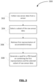
- FIG. 3 shows, in flowchart form, an example process 300 for operating a pseudorandom generator on a mobile computing device.
- the process 300 may be implemented by a mobile computing device, such as the computing device 100 of FIG. 1 .
- the operations of process 300 may be performed by one or more of the modules 192-196 of FIG. 2 .
- the process 300 may be implemented as a set of operations performed by one or more components of the operating system, a standalone software module (e.g. a pseudorandom number generator application), or other software on a mobile device to initialize and operate a pseudorandom generator.
- a standalone software module e.g. a pseudorandom number generator application
- process 300 will be described with reference to an example embodiment in which output data from a single sensor is used. It will be understood, however, that the process 300 may be implemented to incorporate use of output data from a plurality of different sensors on a mobile computing device.
- the mobile device collects raw output data from a sensor of the mobile device.
- the raw output data may, for example, contain data from a single output or multiple outputs from the sensor.
- the device may monitor the sensor, periodically or on a continuous basis, for observation of sensor outputs and associated raw data. For example, various sensor events associated with the sensor may be monitored. A sensor event occurs when a sensor detects a change in the parameters it is measuring. A sensor event may provide, at least, the raw sensor data that triggered the event.
- the device may request to receive raw output data from the sensor. For example, a request may be transmitted to the sensor to provide raw data from one or more future sensor outputs from the sensor.
- the raw data may be pre-processed or minimally processed output data from the sensor that has not been converted to a different format for consumption on the device.
- the raw output data may be data that has not been compressed.
- raw image data from an image sensor of a camera may be collected.
- the image data may be in the form of a raw file.
- the raw file may contain full resolution data as read out from the camera's image sensor pixels.
- raw output data may be saved in a raw file, which is a record of the data captured by the sensor.
- Raw files may contain sensor data (e.g. image pixel intensities, audio frequencies, etc.), sensor metadata, and/or file metadata.
- the format of the raw output data may depend on the type of the sensor.
- the raw output data from the sensor may be converted to a data bit stream.
- the raw output data may be represented in bit streams.
- output data representing pixel intensities and colors at various locations on the image sensor may be represented in bit streams.
- raw, uncompressed audio data from a microphone input may be stored in PCM format.
- the mobile device selects a subset of the collected raw sensor output data.
- the subset may be selected from output data associated with a single output or multiple outputs from the sensor.
- the selected subset may contain bits from the sensor's output data bit stream. For example, bits may be selected for inclusion in the subset according to a predefined selection algorithm or function. That is, the mobile device may implement a selection function in operation 304.
- An objective of the selection function is to identify those portions of the raw sensor data that will not be saved in a final form on the mobile device.
- the mobile device may perform various processing operations (e.g. sharpening, noise reduction, white balancing, compression, etc.) on the acquired sensor data before finally saving in a suitable final format.
- the selection function may be configured to identify subsets of raw sensor data that would be lost or eliminated as a result of the data processing.
- the selection function may interact with a data compression operation for the sensor to specifically select bits that will not be contained in a compressed version of the raw sensor data.
- the selection function may be configured to coordinate with the sensor's compression (e.g. lossy compression) algorithm to identify portions of the raw sensor data which will be discarded in deriving the compressed form of the data.
- Lossy compression may quantize values at lower resolution, or suppress certain component values of a signal in a transform domain.
- the selection function may select bits that will not be preserved in the output of a lossy compression.
- images may be encoded by implementing less resolution for chroma information than for luma information (i.e. chroma subsampling).
- the selection function may be configured to select bits corresponding to the discarded pixels in the chroma components from the raw sensor data representing an image.
- the MPEG-1 standard for audio encoding utilizes psychoacoustics to reduce the data rate required by an audio stream.
- encoded audio may completely discard certain components of the original audio data, either because they are in frequencies where the human ear has limited sensitivity or are masked by other sounds.
- the selection function may be configured to identify bits corresponding to the discarded audio components from raw sensor (e.g. microphone) data.
- raw sensor data may be collected from a time-of-flight (ToF) camera.
- a ToF camera is a camera system that employs time-of-flight techniques to resolve distance between the camera and a subject for each point in an image, by measuring the round trip time of an artificial light signal (e.g. laser, LED).
- a ToF camera may be used for a wide range of applications in, for example, depth measurements, indoor navigation, gesture recognition, motion tracking, and augmented reality.
- a subset of ToF camera sensor data may be selected by the mobile device.
- a selection function may select redundant data associated with various operations being performed on the mobile device. For example, for one or more applications that are running on the mobile device, a selection function may identify subsets of application data (e.g. user-specific data, file data, geolocation data, etc.) which are stored on the mobile device and not currently used by the applications. As another example, if the mobile device includes multiple cameras (e.g. different lenses, such as telephoto lens and monochrome lens) for generating images, a selection function may be configured to identify / select those subsets of raw camera output data that are not currently used in image generation.
- application data e.g. user-specific data, file data, geolocation data, etc.
- a selection function may be configured to identify / select those subsets of raw camera output data that are not currently used in image generation.
- the data which does not make it into the compressed output may be ideal for use in random quantities or as a source of randomness, as it often comprises that part of the output data which contains entropy produced by artifacts of the measurement process (e.g. noise in the low bits of a camera charge coupled device (CCD) sensor or microphone). Importantly, this data also represents part of the output data which will not be recorded or transmitted.
- CCD camera charge coupled device
- the mobile device may be configured to process raw sensor signals from the sensor by, for example, applying noise filters, identifying anomaly/outlier data points, and detecting errors, prior to delivering processed sensor readings for different applications on the mobile device.
- the raw sensor data that is discarded in these processing operations may be included in the sensor data subset selected in operation 304.
- the mobile device may perform compression of the raw sensor data using a compression technique to obtain a compressed output and select bits that are not included in the compressed output for inclusion in the subset.
- a compression technique e.g. lossy compression
- the mobile device may emulate a data encoding method (e.g. lossy compression) that is typically employed by the sensor to identify which bits will not be included in the compressed output.
- the mobile device may perform lossy compression of the raw sensor data and identify bits of the of the sensor data bit stream that are not preserved in the lossy compression output. The identified bits may then be included in the subset of output data obtained in operation 304.
- the mobile device may perform comparisons between collected raw sensor output data and the output of lossy data encoding (e.g. a lossy function) on the mobile device. Such comparison may facilitate identification of raw output data that is not included in compressed output. If a first representation of the raw sensor data and a second representation of the output of the lossy encoding are different (for example, in terms of space domain), a domain transform may be applied to one of the representations, in order to facilitate the comparison of raw sensor data and the output of the lossy encoding. For example, the mobile device may determine a suitable transform function from the first domain associated with the first representation to the second domain associated with the second representation, and apply the determined transform to the first representation. Similarly, a transform function from the domain of the representation of the lossy encoding to the domain of the raw sensor data may be determined.
- lossy data encoding e.g. a lossy function
- the mobile device may select a fixed fraction of a predefined number of low order bits of the sensor data bit stream.
- the mobile device retrieves a first representation of accumulated entropy associated with previously acquired raw sensor data for the sensor.
- the entropy which may be attributed to the output data for those sensor outputs may be captured and stored as numbers or bit representations of numbers.
- the "accumulated entropy" for a sensor represents an accumulation of such numbers or bits associated with the entropy values for previous sensor outputs.
- the first representation may, for example, be a numerical value or a bit string.
- the first representation may be initialized to a static value (e.g. zero) or a value generated using one or more sources of randomness.
- the sensors of the mobile device may have a respective current representation of accumulated entropy. In particular, a unique current representation of accumulated entropy may be maintained for each of one or more sensors.
- the current representations may be stored in a database in association with a respective sensor. Alternatively, each sensor may maintain its own current representation. As new outputs are generated by sensors of the mobile device, the current representations may be updated. In particular, a current representation for a sensor may be combined with a representation of entropy associated with a new sensor output to generate an updated current representation. This current representation, of a function of it, may be used as a source of entropy for the mobile device. Such a source of entropy may, for example, be used to seed, or as a portion of the seed, of a random generator.
- the mobile device In operation 308, the mobile device generates a seed for a pseudorandom number generator based on combining the first representation of accumulated entropy for the sensor and the selected subset of raw sensor output data. That is, the first representation retrieved in operation 306 and the subset of sensor output data selected in operation 304 are combined.
- the seed may comprise an updated version of the first representation, i.e. current representation of accumulated entropy for the sensor.
- the seed may be a numerical value or bit string that is obtained based on the first representation.
- the mobile device may implement an accumulation function which is applied to the first representation and a bit representation of the selected subset of raw output data.
- the accumulation function may employ a combination of operations on bit strings.
- the accumulation function may include at least one of cryptographic hash functions, block ciphers, exclusive or, modular addition or subtraction, or scaling operations to the first representation and the bit representation of the selected subset.
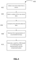
- FIG. 4 shows, in flowchart form, another example process 400 for operating a pseudorandom generator on a mobile computing device. Similar to process 300, the process 400 may be implemented by a mobile computing device, such as the computing device 100 of FIG. 1 . For example, the operations of process 400 may be performed by one or more of the modules 192-196 of FIG. 2 .
- Operations 402, 404, 408 and 410 of process 400 are similar to operations 302, 304, 306 and 308, respectively.
- Raw sensor output data is collected from a sensor, in operation 402.
- the mobile device selects a subset of the collected raw output data for further processing, in operation 404.
- the selected data subset is then compressed to produce a compressed output.
- the mobile device applies a one-way compression function on the selected subset of raw output data, in operation 406.
- the one-way compression function of operation 406 is not intended to be a compression that is used to produce a lower fidelity version of the sensor output. Instead, the compression function is intended to be a one-way cryptographic compression function, typically a secure hash algorithm such as SHA-256.
- the mobile device retrieves a first representation of the accumulated entropy of the sensor in operation 408, and a seed for a pseudorandom number generator is generated based on combining the first representation and the compressed output, in operation 410. That is, the first representation retrieved in operation 408 and the compressed version of the selected output data from operation 406 are combined to produce the seed.
- the seed is generated based on an accumulation function that is applied on the first representation and the compressed output.
- the accumulation function may include a combination of cryptographic hash functions, block ciphers, logical operations (XOR), modular addition or subtraction, or scaling. Various different accumulation functions may be suitable.
- f A C A + SHA ⁇ 256 A mod 2 256 XOR C ⁇ SHA ⁇ 256 C mod 2 256
- A is the first representation of accumulated entropy for the sensor and C denotes the compressed output of operation 406.
- the above function may be static or time-varying.
- the output of f ( A, C ) provides an updated, or current, representation of the accumulated entropy for the sensor, and may serve as a source of entropy (e.g. seed of a PRNG).
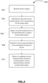
- FIG. 5 shows, in flowchart form, an example process 500 for processing sensor output data that is collected on a mobile computing device.
- the process 500 may be implemented by a mobile computing device, such as the computing device 100 of FIG. 1 .
- the operations of process 500 may be performed by a software module associated with a sensor of the mobile computing device.
- raw sensor output data from the sensor is received by the software module.
- a bit stream representation of the raw output data is obtained.
- the software module identifies bits that will not be preserved by a first compression of the raw output data.
- the first compression may be a default compression algorithm that is applied to output data from the sensor. That is, the software module determines which compression function is typically applied on output data from the sensor and identifies those bits of the current raw output data bit stream that will not be contained in the compressed version.
- a second compression function is applied on the identified bits to obtain a compressed output.
- the second compression function is a one-way cryptographic compression function, such as a secure hash algorithm (e.g. SHA-256).
- the software module retrieves a current representation of accumulated entropy for the sensor, in operation 508.
- the current representation represents an accumulation of entropy values associated with one or more previous sensor outputs from the sensor, and may be stored in association with the sensor in a database on the mobile device.
- an updated current representation is obtained based on combining the current representation as retrieved and the compressed output.
- an accumulation function such as the functions (1) and (2) described above, may be employed to determine the current representation.
- the process 500 may thus provide a way for a sensor and associated software to maintain a current representation of entropy values that are accumulated with new sensor outputs from the sensor.
Landscapes
- Engineering & Computer Science (AREA)
- Theoretical Computer Science (AREA)
- Physics & Mathematics (AREA)
- General Physics & Mathematics (AREA)
- Computer Security & Cryptography (AREA)
- Computer Networks & Wireless Communication (AREA)
- Signal Processing (AREA)
- Computational Mathematics (AREA)
- Mathematical Analysis (AREA)
- Mathematical Optimization (AREA)
- Pure & Applied Mathematics (AREA)
- General Engineering & Computer Science (AREA)
- Power Engineering (AREA)
- Nonlinear Science (AREA)
- Telephone Function (AREA)
Claims (9)
- Ein Verfahren (300, 400, 500) zum Betätigen eines Pseudozufallszahlengenerators auf einer mobilen Rechenvorrichtung, wobei das Verfahren Folgendes beinhaltet:Sammeln (302, 402, 502) von unverarbeiteten Sensordaten von mindestens einem Sensor, der mit der mobilen Rechenvorrichtung assoziiert ist;Auswählen (304, 404) einer Teilmenge der unverarbeiteten Sensordaten basierend auf:Komprimieren (406) der unverarbeiteten Sensordaten unter Verwendung einer Technik verlustbehafteter Kompression, um eine verlustbehaftet komprimierte Sensordatenausgabe zu erhalten; undAuswählen (504), zur Aufnahme in die Teilmenge, von Teilen der unverarbeiteten Sensordaten, die nicht in der verlustbehaftet komprimierten Sensordatenausgabe umfasst sind;Anwenden (506) einer einseitigen kryptographischen Kompression auf die ausgewählte Teilmenge, um eine erste komprimierte Ausgabe zu erhalten;Abrufen (306, 408, 508) einer ersten Darstellung akkumulierter Entropie, die mit einer oder mehreren vorher gewonnenen unverarbeiteten Sensordatenmengen für den mindestens einen Sensor assoziiert ist; undGenerieren (308, 410, 510) eines Seeds für einen Pseudozufallszahlengenerator basierend auf dem Kombinieren der ersten Darstellung und der ersten komprimierten Ausgabe.
- Verfahren (300, 400, 500) gemäß Anspruch 1, wobei die erste Darstellung eine erste Bitfolge beinhaltet und wobei das Generieren (308, 410, 510) des Seeds das Erhalten einer zweiten Bitfolge basierend auf der ersten Bitfolge beinhaltet.
- Verfahren (300, 400, 500) gemäß Anspruch 1, wobei das Anwenden (506) der einseitigen kryptographischen Kompression auf die ausgewählte (504) Teilmenge das Anwenden einer kryptographischen Hash-Funktion auf die ausgewählte Teilmenge beinhaltet.
- Verfahren (300, 400, 500) gemäß Anspruch 3, wobei das Kombinieren der ersten Darstellung und der ersten komprimierten Ausgabe das Anwenden von mindestens einem von "exklusivem Oder", Addition, Subtraktion oder Skalierungsoperationen auf die erste Darstellung und die erste komprimierte Ausgabe beinhaltet.
- Verfahren (300, 400, 500) gemäß einem der vorhergehenden Ansprüche, das ferner das Initialisieren der ersten Darstellung auf einen statischen Wert beinhaltet.
- Verfahren (300, 400, 500) gemäß einem der vorhergehenden Ansprüche, das ferner das Aktualisieren der ersten Darstellung zum Inkorporieren des generierten (510) Seeds beinhaltet.
- Verfahren (300, 400, 500) gemäß einem der vorhergehenden Ansprüche, wobei das Auswählen (304, 404) der Teilmenge der unverarbeiteten Sensordaten das Auswählen eines festgelegten Bruchteils einer vordefinierten Anzahl von niedrigwertigen Bits eines Datenbitstroms, der mit dem mindestens einen Sensor assoziiert ist, beinhaltet.
- Eine mobile Rechenvorrichtung (100), die Folgendes beinhaltet:mindestens einen Sensor (108, 109, 110);einen Speicher (144, 146, 148); undeinen mit dem mindestens einen Sensor und dem Speicher gekoppelten Prozessor (140), wobei der Prozessor konfiguriert ist, um das Verfahren gemäß einem vorhergehenden Anspruch vorzunehmen.
- Ein Computerprogramm, das, wenn es auf einer mobilen Rechenvorrichtung (100) ausgeführt wird, konfiguriert ist, um das Verfahren gemäß einem der Ansprüche 1 bis 7 vorzunehmen.
Applications Claiming Priority (1)
| Application Number | Priority Date | Filing Date | Title |
|---|---|---|---|
| US16/431,845 US11310033B2 (en) | 2019-06-05 | 2019-06-05 | System and method for operating pseudorandom generators |
Publications (3)
| Publication Number | Publication Date |
|---|---|
| EP3748898A1 EP3748898A1 (de) | 2020-12-09 |
| EP3748898B1 true EP3748898B1 (de) | 2024-11-13 |
| EP3748898C0 EP3748898C0 (de) | 2024-11-13 |
Family
ID=70616966
Family Applications (1)
| Application Number | Title | Priority Date | Filing Date |
|---|---|---|---|
| EP20173464.7A Active EP3748898B1 (de) | 2019-06-05 | 2020-05-07 | System und verfahren zum betrieb von pseudozufallsgeneratoren |
Country Status (2)
| Country | Link |
|---|---|
| US (1) | US11310033B2 (de) |
| EP (1) | EP3748898B1 (de) |
Families Citing this family (12)
| Publication number | Priority date | Publication date | Assignee | Title |
|---|---|---|---|---|
| US11277658B1 (en) | 2020-08-21 | 2022-03-15 | Beam, Inc. | Integrating overlaid digital content into displayed data via graphics processing circuitry |
| US20220109995A1 (en) * | 2020-10-05 | 2022-04-07 | John Vermes | Generation and implementation of distinctive event based cryptographic token via machine recognized event |
| US11481933B1 (en) | 2021-04-08 | 2022-10-25 | Mobeus Industries, Inc. | Determining a change in position of displayed digital content in subsequent frames via graphics processing circuitry |
| US11483156B1 (en) | 2021-04-30 | 2022-10-25 | Mobeus Industries, Inc. | Integrating digital content into displayed data on an application layer via processing circuitry of a server |
| US11477020B1 (en) | 2021-04-30 | 2022-10-18 | Mobeus Industries, Inc. | Generating a secure random number by determining a change in parameters of digital content in subsequent frames via graphics processing circuitry |
| US11682101B2 (en) | 2021-04-30 | 2023-06-20 | Mobeus Industries, Inc. | Overlaying displayed digital content transmitted over a communication network via graphics processing circuitry using a frame buffer |
| US11601276B2 (en) | 2021-04-30 | 2023-03-07 | Mobeus Industries, Inc. | Integrating and detecting visual data security token in displayed data via graphics processing circuitry using a frame buffer |
| US11586835B2 (en) | 2021-04-30 | 2023-02-21 | Mobeus Industries, Inc. | Integrating overlaid textual digital content into displayed data via graphics processing circuitry using a frame buffer |
| US11475610B1 (en) | 2021-04-30 | 2022-10-18 | Mobeus Industries, Inc. | Controlling interactivity of digital content overlaid onto displayed data via graphics processing circuitry using a frame buffer |
| US11562153B1 (en) | 2021-07-16 | 2023-01-24 | Mobeus Industries, Inc. | Systems and methods for recognizability of objects in a multi-layer display |
| US12488139B2 (en) * | 2021-09-23 | 2025-12-02 | Intuit Inc. | Data services with privacy preservation and repeatability |
| CN115632782B (zh) * | 2022-12-22 | 2023-03-21 | 湖南密码工程研究中心有限公司 | 基于sm4计数器模式的随机数生成方法、系统及设备 |
Family Cites Families (12)
| Publication number | Priority date | Publication date | Assignee | Title |
|---|---|---|---|---|
| US7571199B1 (en) | 2000-11-15 | 2009-08-04 | Microsoft Corporation | Method and apparatus for generating random numbers |
| US7532765B2 (en) * | 2002-12-30 | 2009-05-12 | Intel Corporation | Run length encoded digital image |
| US8379848B2 (en) | 2011-07-07 | 2013-02-19 | Cape Light Institute, Inc. | Method of providing a portable true random number generator based on the microstructure and noise found in digital images |
| US8787564B2 (en) * | 2011-11-30 | 2014-07-22 | Certicom Corp. | Assessing cryptographic entropy |
| US20150078457A1 (en) * | 2013-09-13 | 2015-03-19 | Qualcomm Incorporated | Representation format signaling in multi-layer video coding |
| US20150117636A1 (en) * | 2013-10-30 | 2015-04-30 | Apriva, Llc | System and method for performing a secure cryptographic operation on a mobile device |
| US9466377B2 (en) * | 2014-02-26 | 2016-10-11 | Infineon Technologies Ag | Method and device for processing an erase counter |
| US9658832B2 (en) * | 2015-05-18 | 2017-05-23 | Red Hat Israel, Ltd. | Multi-factor entropy sourcing for random number generators |
| US10452357B2 (en) * | 2015-12-22 | 2019-10-22 | Intel Corporation | Generation of distinctive value based on true random input |
| EP3185555B1 (de) * | 2015-12-23 | 2023-07-05 | Université de Genève | Bildkompressionsverfahren mit vernachlässigbarem und quantifizierbarem informationsverlust und hoher verdichtungsrate |
| US10778412B2 (en) * | 2017-12-28 | 2020-09-15 | Intel Corporation | Multi-domain convolutional neural network |
| US10728420B2 (en) * | 2018-04-11 | 2020-07-28 | Wind River Systems, Inc. | Lossy compression for images and signals by identifying regions with low density of features |
-
2019
- 2019-06-05 US US16/431,845 patent/US11310033B2/en active Active
-
2020
- 2020-05-07 EP EP20173464.7A patent/EP3748898B1/de active Active
Also Published As
| Publication number | Publication date |
|---|---|
| US20200389293A1 (en) | 2020-12-10 |
| EP3748898A1 (de) | 2020-12-09 |
| US11310033B2 (en) | 2022-04-19 |
| EP3748898C0 (de) | 2024-11-13 |
Similar Documents
| Publication | Publication Date | Title |
|---|---|---|
| EP3748898B1 (de) | System und verfahren zum betrieb von pseudozufallsgeneratoren | |
| US20150117643A1 (en) | System and method for performing a secure cryptographic operation on a mobile device combining data from multiple sensors | |
| CN112040337A (zh) | 视频的水印添加和提取方法、装置、设备及存储介质 | |
| JP6300792B2 (ja) | キャプチャされたデータの強化 | |
| US20240405969A1 (en) | Data processing method and device based on homomorphic encryption | |
| US20200272748A1 (en) | Methods and apparatus for validating media content | |
| KR102827848B1 (ko) | 영상을 처리하는 전자 장치 및 그 영상 처리 방법 | |
| EP3438838A1 (de) | Dienstbereitstellungssystem, dienstempfangssystem, dienstbereitstellungsverfahren und programm | |
| US9148472B2 (en) | Server, electronic device, server control method, and computer-readable medium | |
| CN107733874A (zh) | 信息处理方法、装置、计算机设备和存储介质 | |
| CN115495169B (zh) | 数据获取、页面生成方法、装置、设备及可读存储介质 | |
| CN116743351B (zh) | 密钥管理方法、装置、设备及存储介质 | |
| EP3438837A1 (de) | Dienstbereitstellungssystem, dienstlieferungssystem, dienstbereitstellungsverfahren und programm | |
| US20110064311A1 (en) | Electronic apparatus and image search method | |
| CN114615520A (zh) | 字幕定位方法、装置、计算机设备及介质 | |
| EP3438860B1 (de) | Dienstbereitstellungssystem, dienstaustauschsystem, dienstbereitstellungsverfahren und programm | |
| US10534904B2 (en) | Input processing system, information storage device, information processing device, and input method | |
| CN113204548B (zh) | 数据存储方法、装置、终端及存储介质 | |
| TWI752519B (zh) | 用於多媒體信號識別的電子裝置及其操作方法 | |
| Nixon | Secure and Power-Efficient Computing on Mobile Platforms | |
| KR20220133533A (ko) | 보안 데이터를 탈중앙화 네트워크를 통해 관리하는 전자 장치 및 이의 동작 방법 | |
| CN120956514A (zh) | 图片拦截方法、装置、设备及存储介质 | |
| CN119450049A (zh) | 运动矢量确定方法、芯片、电子设备和可读存储介质 | |
| JP2022183806A (ja) | 画像出力システム、画像出力方法、及びプログラム | |
| HK40034936A (en) | Method and apparatus for adding and extracting video watermak, device and storage medium |
Legal Events
| Date | Code | Title | Description |
|---|---|---|---|
| PUAI | Public reference made under article 153(3) epc to a published international application that has entered the european phase |
Free format text: ORIGINAL CODE: 0009012 |
|
| STAA | Information on the status of an ep patent application or granted ep patent |
Free format text: STATUS: THE APPLICATION HAS BEEN PUBLISHED |
|
| AK | Designated contracting states |
Kind code of ref document: A1 Designated state(s): AL AT BE BG CH CY CZ DE DK EE ES FI FR GB GR HR HU IE IS IT LI LT LU LV MC MK MT NL NO PL PT RO RS SE SI SK SM TR |
|
| AX | Request for extension of the european patent |
Extension state: BA ME |
|
| STAA | Information on the status of an ep patent application or granted ep patent |
Free format text: STATUS: REQUEST FOR EXAMINATION WAS MADE |
|
| 17P | Request for examination filed |
Effective date: 20210609 |
|
| RBV | Designated contracting states (corrected) |
Designated state(s): AL AT BE BG CH CY CZ DE DK EE ES FI FR GB GR HR HU IE IS IT LI LT LU LV MC MK MT NL NO PL PT RO RS SE SI SK SM TR |
|
| STAA | Information on the status of an ep patent application or granted ep patent |
Free format text: STATUS: EXAMINATION IS IN PROGRESS |
|
| 17Q | First examination report despatched |
Effective date: 20220908 |
|
| GRAP | Despatch of communication of intention to grant a patent |
Free format text: ORIGINAL CODE: EPIDOSNIGR1 |
|
| STAA | Information on the status of an ep patent application or granted ep patent |
Free format text: STATUS: GRANT OF PATENT IS INTENDED |
|
| RIC1 | Information provided on ipc code assigned before grant |
Ipc: H04W 12/60 20210101ALI20240517BHEP Ipc: H04L 9/08 20060101ALI20240517BHEP Ipc: G06F 7/58 20060101ALI20240517BHEP Ipc: H04L 9/06 20060101AFI20240517BHEP |
|
| INTG | Intention to grant announced |
Effective date: 20240621 |
|
| RAP1 | Party data changed (applicant data changed or rights of an application transferred) |
Owner name: MALIKIE INNOVATIONS LIMITED |
|
| GRAS | Grant fee paid |
Free format text: ORIGINAL CODE: EPIDOSNIGR3 |
|
| GRAA | (expected) grant |
Free format text: ORIGINAL CODE: 0009210 |
|
| STAA | Information on the status of an ep patent application or granted ep patent |
Free format text: STATUS: THE PATENT HAS BEEN GRANTED |
|
| AK | Designated contracting states |
Kind code of ref document: B1 Designated state(s): AL AT BE BG CH CY CZ DE DK EE ES FI FR GB GR HR HU IE IS IT LI LT LU LV MC MK MT NL NO PL PT RO RS SE SI SK SM TR |
|
| REG | Reference to a national code |
Ref country code: GB Ref legal event code: FG4D |
|
| REG | Reference to a national code |
Ref country code: CH Ref legal event code: EP |
|
| REG | Reference to a national code |
Ref country code: IE Ref legal event code: FG4D |
|
| REG | Reference to a national code |
Ref country code: DE Ref legal event code: R096 Ref document number: 602020041177 Country of ref document: DE |
|
| U01 | Request for unitary effect filed |
Effective date: 20241204 |
|
| U07 | Unitary effect registered |
Designated state(s): AT BE BG DE DK EE FI FR IT LT LU LV MT NL PT RO SE SI Effective date: 20241213 |
|
| PG25 | Lapsed in a contracting state [announced via postgrant information from national office to epo] |
Ref country code: IS Free format text: LAPSE BECAUSE OF FAILURE TO SUBMIT A TRANSLATION OF THE DESCRIPTION OR TO PAY THE FEE WITHIN THE PRESCRIBED TIME-LIMIT Effective date: 20250313 Ref country code: HR Free format text: LAPSE BECAUSE OF FAILURE TO SUBMIT A TRANSLATION OF THE DESCRIPTION OR TO PAY THE FEE WITHIN THE PRESCRIBED TIME-LIMIT Effective date: 20241113 |
|
| PG25 | Lapsed in a contracting state [announced via postgrant information from national office to epo] |
Ref country code: ES Free format text: LAPSE BECAUSE OF FAILURE TO SUBMIT A TRANSLATION OF THE DESCRIPTION OR TO PAY THE FEE WITHIN THE PRESCRIBED TIME-LIMIT Effective date: 20241113 |
|
| PG25 | Lapsed in a contracting state [announced via postgrant information from national office to epo] |
Ref country code: NO Free format text: LAPSE BECAUSE OF FAILURE TO SUBMIT A TRANSLATION OF THE DESCRIPTION OR TO PAY THE FEE WITHIN THE PRESCRIBED TIME-LIMIT Effective date: 20250213 |
|
| PG25 | Lapsed in a contracting state [announced via postgrant information from national office to epo] |
Ref country code: GR Free format text: LAPSE BECAUSE OF FAILURE TO SUBMIT A TRANSLATION OF THE DESCRIPTION OR TO PAY THE FEE WITHIN THE PRESCRIBED TIME-LIMIT Effective date: 20250214 |
|
| PG25 | Lapsed in a contracting state [announced via postgrant information from national office to epo] |
Ref country code: PL Free format text: LAPSE BECAUSE OF FAILURE TO SUBMIT A TRANSLATION OF THE DESCRIPTION OR TO PAY THE FEE WITHIN THE PRESCRIBED TIME-LIMIT Effective date: 20241113 |
|
| PG25 | Lapsed in a contracting state [announced via postgrant information from national office to epo] |
Ref country code: RS Free format text: LAPSE BECAUSE OF FAILURE TO SUBMIT A TRANSLATION OF THE DESCRIPTION OR TO PAY THE FEE WITHIN THE PRESCRIBED TIME-LIMIT Effective date: 20250213 |
|
| U20 | Renewal fee for the european patent with unitary effect paid |
Year of fee payment: 6 Effective date: 20250526 |
|
| PG25 | Lapsed in a contracting state [announced via postgrant information from national office to epo] |
Ref country code: SM Free format text: LAPSE BECAUSE OF FAILURE TO SUBMIT A TRANSLATION OF THE DESCRIPTION OR TO PAY THE FEE WITHIN THE PRESCRIBED TIME-LIMIT Effective date: 20241113 |
|
| PGFP | Annual fee paid to national office [announced via postgrant information from national office to epo] |
Ref country code: GB Payment date: 20250520 Year of fee payment: 6 |
|
| PG25 | Lapsed in a contracting state [announced via postgrant information from national office to epo] |
Ref country code: SK Free format text: LAPSE BECAUSE OF FAILURE TO SUBMIT A TRANSLATION OF THE DESCRIPTION OR TO PAY THE FEE WITHIN THE PRESCRIBED TIME-LIMIT Effective date: 20241113 |
|
| PG25 | Lapsed in a contracting state [announced via postgrant information from national office to epo] |
Ref country code: CZ Free format text: LAPSE BECAUSE OF FAILURE TO SUBMIT A TRANSLATION OF THE DESCRIPTION OR TO PAY THE FEE WITHIN THE PRESCRIBED TIME-LIMIT Effective date: 20241113 |
|
| PLBE | No opposition filed within time limit |
Free format text: ORIGINAL CODE: 0009261 |
|
| STAA | Information on the status of an ep patent application or granted ep patent |
Free format text: STATUS: NO OPPOSITION FILED WITHIN TIME LIMIT |
|
| 26N | No opposition filed |
Effective date: 20250814 |