EP3748839A1 - Dc generator system - Google Patents
Dc generator system Download PDFInfo
- Publication number
- EP3748839A1 EP3748839A1 EP19212675.3A EP19212675A EP3748839A1 EP 3748839 A1 EP3748839 A1 EP 3748839A1 EP 19212675 A EP19212675 A EP 19212675A EP 3748839 A1 EP3748839 A1 EP 3748839A1
- Authority
- EP
- European Patent Office
- Prior art keywords
- generator
- vfg
- alternating current
- gearbox
- rectifier
- Prior art date
- Legal status (The legal status is an assumption and is not a legal conclusion. Google has not performed a legal analysis and makes no representation as to the accuracy of the status listed.)
- Granted
Links
Images
Classifications
-
- H—ELECTRICITY
- H02—GENERATION; CONVERSION OR DISTRIBUTION OF ELECTRIC POWER
- H02P—CONTROL OR REGULATION OF ELECTRIC MOTORS, ELECTRIC GENERATORS OR DYNAMO-ELECTRIC CONVERTERS; CONTROLLING TRANSFORMERS, REACTORS OR CHOKE COILS
- H02P9/00—Arrangements for controlling electric generators for the purpose of obtaining a desired output
-
- H—ELECTRICITY
- H02—GENERATION; CONVERSION OR DISTRIBUTION OF ELECTRIC POWER
- H02P—CONTROL OR REGULATION OF ELECTRIC MOTORS, ELECTRIC GENERATORS OR DYNAMO-ELECTRIC CONVERTERS; CONTROLLING TRANSFORMERS, REACTORS OR CHOKE COILS
- H02P9/00—Arrangements for controlling electric generators for the purpose of obtaining a desired output
- H02P9/10—Control effected upon generator excitation circuit to reduce harmful effects of overloads or transients, e.g. sudden application of load, sudden removal of load, sudden change of load
- H02P9/102—Control effected upon generator excitation circuit to reduce harmful effects of overloads or transients, e.g. sudden application of load, sudden removal of load, sudden change of load for limiting effects of transients
-
- H—ELECTRICITY
- H02—GENERATION; CONVERSION OR DISTRIBUTION OF ELECTRIC POWER
- H02P—CONTROL OR REGULATION OF ELECTRIC MOTORS, ELECTRIC GENERATORS OR DYNAMO-ELECTRIC CONVERTERS; CONTROLLING TRANSFORMERS, REACTORS OR CHOKE COILS
- H02P9/00—Arrangements for controlling electric generators for the purpose of obtaining a desired output
- H02P9/14—Arrangements for controlling electric generators for the purpose of obtaining a desired output by variation of field
- H02P9/26—Arrangements for controlling electric generators for the purpose of obtaining a desired output by variation of field using discharge tubes or semiconductor devices
- H02P9/30—Arrangements for controlling electric generators for the purpose of obtaining a desired output by variation of field using discharge tubes or semiconductor devices using semiconductor devices
- H02P9/305—Arrangements for controlling electric generators for the purpose of obtaining a desired output by variation of field using discharge tubes or semiconductor devices using semiconductor devices controlling voltage
- H02P9/307—Arrangements for controlling electric generators for the purpose of obtaining a desired output by variation of field using discharge tubes or semiconductor devices using semiconductor devices controlling voltage more than one voltage output
-
- B—PERFORMING OPERATIONS; TRANSPORTING
- B64—AIRCRAFT; AVIATION; COSMONAUTICS
- B64D—EQUIPMENT FOR FITTING IN OR TO AIRCRAFT; FLIGHT SUITS; PARACHUTES; ARRANGEMENT OR MOUNTING OF POWER PLANTS OR PROPULSION TRANSMISSIONS IN AIRCRAFT
- B64D2221/00—Electric power distribution systems onboard aircraft
-
- H—ELECTRICITY
- H02—GENERATION; CONVERSION OR DISTRIBUTION OF ELECTRIC POWER
- H02P—CONTROL OR REGULATION OF ELECTRIC MOTORS, ELECTRIC GENERATORS OR DYNAMO-ELECTRIC CONVERTERS; CONTROLLING TRANSFORMERS, REACTORS OR CHOKE COILS
- H02P2101/00—Special adaptation of control arrangements for generators
- H02P2101/25—Special adaptation of control arrangements for generators for combustion engines
-
- H—ELECTRICITY
- H02—GENERATION; CONVERSION OR DISTRIBUTION OF ELECTRIC POWER
- H02P—CONTROL OR REGULATION OF ELECTRIC MOTORS, ELECTRIC GENERATORS OR DYNAMO-ELECTRIC CONVERTERS; CONTROLLING TRANSFORMERS, REACTORS OR CHOKE COILS
- H02P2101/00—Special adaptation of control arrangements for generators
- H02P2101/30—Special adaptation of control arrangements for generators for aircraft
Definitions
- the present disclosure relates to managing electrical system, and more particularly to reducing torque ripple in electrical power generation systems.
- a system configured to control power transfer of an aircraft engine includes a variable frequency generator (VFG) including a generator configured to direct alternating current to a first rectifier configured to convert alternating current from the VFG to direct current and drive it to a High Voltage DC (HVDC) Bus Network and a second variable frequency generator configured to direct alternating current to a second rectifier configured to convert alternating current from the second generator to direct current and direct it to the HVDC Bus Network, a speed correcting gearbox operatively connected to the VFG configured to align generator frequency to the second generator frequency, a VFG control unit operatively connected to the generator and to the electric module configured to control the VFG, and a second generator control unit operatively connected to the second generator and the HVDC Bus Network configured to control the second generator.
- VFG variable frequency generator
- HVDC High Voltage DC
- the first VFG can be operatively connected to a low-pressure spool gearbox spool configured to control an engine of an aircraft and the speed-correcting gearbox can be located between the VFG and the low pressure gearbox.
- the second generator can be operatively connected to a high-pressure gearbox spool configured to control the engine of the aircraft.
- the output of the first rectifier can be 540 volts and the output of the second rectifier can be 540 volts.
- the HVDC Bus Network includes a pair of independent DC busses configured to distribute power.
- a method includes driving alternating current from a first generator connected to a low pressure gearbox spool, driving alternating current from a second generator conencted to a high pressure gearbox spool, and aligning a frequency output of the first generator to a frequency output of the second generator in order to control performance parameters of a direct current system of an aircraft, comprising reducing voltage ripple and reducing load ripple.
- the first generator can direct 540 volts to a first rectifier and the second generator can direct 540 volts to a second rectifier.
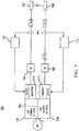
- Fig. 1 is block diagram view of the frequency correcting system.
- Fig. 1 a partial view of an exemplary embodiment of a direct current generation system in accordance with the disclosure is shown in Fig. 1 and is designated generally by reference character 100.
- the methods and systems of the disclosure can be used to decrease the bus voltage ripple, which in turn improves system efficiencies.
- Fig. 1 shows a variable frequency generator (VFG) 102 configured to direct alternating current to a first rectifier 104, which is configured to convert alternating current from a generator 110 to direct current and drive it to an HVDC Bus Network 106 responsible for distributing power to various aircraft components.
- a variable frequency second generator (VFG) 103 is shown including a second generator 111 configured to direct alternating current to a second rectifier 105 configured to convert alternating current from the second generator 111 and also direct it to the HVDC Bus Network 106.
- the HVDC Bus Network 106 includes a pair of independent DC busses 107/108 configured to distribute power to various parts of the aircraft.
- a speed correcting gearbox 130 is operatively connected to the VFG configured to align generator frequency output to the second generator frequency output.
- a VFG control unit 112 is operatively connected to the generator 110 and to the electric module 106 configured to control the VFG 102 and a separate second generator control unit 113 is operatively connected to the second generator 111 and the HVDC Bus Network 106 configured to control the second generator. It is further conceived that speed correction can be located on high spool generator to align the frequency instead of the low spool.
- the VFG 102 is operatively connected to a low-pressure spool gearbox 114 and the speed-correcting gearbox 110 is located between the VFG 102 and the low pressure gearbox 114.
- the second generator 111 is operatively connected to a high-pressure gearbox spool.
- a method for controlling the system discussed above includes driving alternating current from a first generator (VFG) connected to a low pressure gearbox spool resulting in a first frequency output, driving alternating current from a second generator connected to a high pressure gearbox spool resulting in a second frequency output and aligning the frequency output of the first generator to the frequency output of the second generator in order to control performance parameters of a direct current system of an aircraft. Aligning the frequencies is intended to reducing voltage ripple, and load ripple that is caused by misaligned frequency outputs.
Landscapes
- Engineering & Computer Science (AREA)
- Power Engineering (AREA)
- Control Of Eletrric Generators (AREA)
- Aviation & Aerospace Engineering (AREA)
Abstract
Description
- The present disclosure relates to managing electrical system, and more particularly to reducing torque ripple in electrical power generation systems.
- In High Voltage DC, such as 540 volts, parallel applications, DC voltage ripple on the bus produces unacceptable system performance parameters, such as reduced LRU efficiencies, torque ripple, load ripple and contactor control issues, and reduced overall system reliability.
- Conventional methods and systems have generally been considered unsatisfactory for their intended purpose of controlling and reducing torque ripple in the aforementioned systems. There is a need in the art for electrical management systems having reduced torque ripple and reduced load ripple. There also remains a need in the art for such systems that are economically viable. The present disclosure may provide a solution for at least one of these remaining challenges.
- A system configured to control power transfer of an aircraft engine includes a variable frequency generator (VFG) including a generator configured to direct alternating current to a first rectifier configured to convert alternating current from the VFG to direct current and drive it to a High Voltage DC (HVDC) Bus Network and a second variable frequency generator configured to direct alternating current to a second rectifier configured to convert alternating current from the second generator to direct current and direct it to the HVDC Bus Network, a speed correcting gearbox operatively connected to the VFG configured to align generator frequency to the second generator frequency, a VFG control unit operatively connected to the generator and to the electric module configured to control the VFG, and a second generator control unit operatively connected to the second generator and the HVDC Bus Network configured to control the second generator.
- The first VFG can be operatively connected to a low-pressure spool gearbox spool configured to control an engine of an aircraft and the speed-correcting gearbox can be located between the VFG and the low pressure gearbox. The second generator can be operatively connected to a high-pressure gearbox spool configured to control the engine of the aircraft. The output of the first rectifier can be 540 volts and the output of the second rectifier can be 540 volts.
- The HVDC Bus Network includes a pair of independent DC busses configured to distribute power.
- A method includes driving alternating current from a first generator connected to a low pressure gearbox spool, driving alternating current from a second generator conencted to a high pressure gearbox spool, and aligning a frequency output of the first generator to a frequency output of the second generator in order to control performance parameters of a direct current system of an aircraft, comprising reducing voltage ripple and reducing load ripple.
- The first generator (VFG) can direct 540 volts to a first rectifier and the second generator can direct 540 volts to a second rectifier. These and other features of the systems and methods of the subject disclosure will become more readily apparent to those skilled in the art from the following detailed description of the preferred embodiments taken in conjunction with the drawings.
- So that those skilled in the art to which the subject invention appertains will readily understand how to make and use the devices and methods of the subject invention without undue experimentation, preferred embodiments thereof will be described in detail herein below with reference to certain figures, wherein:
Fig. 1 is block diagram view of the frequency correcting system. - Reference will now be made to the drawings wherein like reference numerals identify similar structural features or aspects of the subject invention. For purposes of explanation and illustration, and not limitation, a partial view of an exemplary embodiment of a direct current generation system in accordance with the disclosure is shown in
Fig. 1 and is designated generally byreference character 100. The methods and systems of the disclosure can be used to decrease the bus voltage ripple, which in turn improves system efficiencies. -
Fig. 1 shows a variable frequency generator (VFG) 102 configured to direct alternating current to afirst rectifier 104, which is configured to convert alternating current from agenerator 110 to direct current and drive it to an HVDC Bus Network 106 responsible for distributing power to various aircraft components. A variable frequency second generator (VFG) 103 is shown including asecond generator 111 configured to direct alternating current to asecond rectifier 105 configured to convert alternating current from thesecond generator 111 and also direct it to the HVDC Bus Network 106. The HVDC Bus Network 106 includes a pair ofindependent DC busses 107/108 configured to distribute power to various parts of the aircraft. - Further shown in
Fig. 1 , aspeed correcting gearbox 130 is operatively connected to the VFG configured to align generator frequency output to the second generator frequency output. AVFG control unit 112 is operatively connected to thegenerator 110 and to the electric module 106 configured to control the VFG 102 and a separate secondgenerator control unit 113 is operatively connected to thesecond generator 111 and the HVDC Bus Network 106 configured to control the second generator. It is further conceived that speed correction can be located on high spool generator to align the frequency instead of the low spool. - The VFG 102 is operatively connected to a low-
pressure spool gearbox 114 and the speed-correctinggearbox 110 is located between the VFG 102 and thelow pressure gearbox 114. Thesecond generator 111 is operatively connected to a high-pressure gearbox spool. - A method for controlling the system discussed above is also disclosed. The method includes driving alternating current from a first generator (VFG) connected to a low pressure gearbox spool resulting in a first frequency output, driving alternating current from a second generator connected to a high pressure gearbox spool resulting in a second frequency output and aligning the frequency output of the first generator to the frequency output of the second generator in order to control performance parameters of a direct current system of an aircraft. Aligning the frequencies is intended to reducing voltage ripple, and load ripple that is caused by misaligned frequency outputs.
- The methods and systems of the present disclosure, as described above and shown in the drawings, provide for electrical control system with superior properties including increased reliability and stability, and. While the apparatus and methods of the subject disclosure have been showing and described with reference to embodiments, those skilled in the art will readily appreciate that changes and/or modifications may be made thereto without departing from the spirit and score of the subject disclosure.
Claims (13)
- A system comprising:a variable frequency generator (VFG) (102) including a generator (110) configured to conduct alternating current to a first rectifier (104) configured to convert alternating current from the VFG (102) to direct current and drive it to an HVDC Bus Network (106);a variable frequency second generator (103) including a second generator (111) configured to conduct alternating current to a second rectifier (105) configured to convert alternating current from the second generator (111) to direct current and direct it to the HVDC Bus Network (106);a speed correcting gearbox (130) operatively connected to the first VFG configured to align generator frequency to the second generator frequency;a VFG control unit (112) operatively connected to the generator configured to control the VFG input speed and regulation; anda second generator control unit (113) operatively connected to the second generator and the HVDC Bus Network configured to control the second generator regulation.
- The system of claim 1, wherein the VFG (102) is operatively connected to a low-pressure spool gearbox spool engine of an aircraft.
- The system of claim 2, wherein the speed-correcting gearbox (130) is located between the VFG and the low-pressure gearbox.
- The system of claim 2, wherein the second generator (111) is operatively connected to a high-pressure gearbox spool engine of the aircraft.
- The system of any preceding claim, wherein the output of the first rectifier (104) is 540 volts.
- The system of any preceding claim, wherein the output of the second rectifier (105) is 540 volts.
- The system of any preceding claim, wherein the HVDC Bus Network includes a pair of independent DC busses configured to distribute power.
- The system of any preceding claim, wherein the system is configured to control power transfer of an aircraft engine.
- A method comprising:driving alternating current from a first generator connected to a low pressure gearbox spool;driving alternating current from a second generator connected to a high pressure gearbox spool; andaligning a frequency output of the first generator to a frequency output of the second generator in order to control performance parameters of a direct current system of an aircraft.
- The method of claim 9, further comprising reducing voltage ripple.
- The method of claim 9, further comprising reducing load ripple.
- The method of claim 9, wherein the first generator (VFG) conducts 115/230 volts AC to a first rectifier which converts to 540 Vdc output.
- The method of claim 9, wherein the second generator conducts 115/230 volts AC to a second rectifier which converts to 540 Vdc output.
Applications Claiming Priority (1)
| Application Number | Priority Date | Filing Date | Title |
|---|---|---|---|
| US16/429,953 US10868483B1 (en) | 2019-06-03 | 2019-06-03 | DC generator system |
Publications (2)
| Publication Number | Publication Date |
|---|---|
| EP3748839A1 true EP3748839A1 (en) | 2020-12-09 |
| EP3748839B1 EP3748839B1 (en) | 2022-12-28 |
Family
ID=68762464
Family Applications (1)
| Application Number | Title | Priority Date | Filing Date |
|---|---|---|---|
| EP19212675.3A Active EP3748839B1 (en) | 2019-06-03 | 2019-11-29 | Dc generator system |
Country Status (2)
| Country | Link |
|---|---|
| US (1) | US10868483B1 (en) |
| EP (1) | EP3748839B1 (en) |
Families Citing this family (2)
| Publication number | Priority date | Publication date | Assignee | Title |
|---|---|---|---|---|
| US11355929B1 (en) | 2021-05-24 | 2022-06-07 | Hamilton Sundstrand Corporation | Power sharing coordination of paralleled sources |
| US12057800B2 (en) | 2022-02-11 | 2024-08-06 | Hamilton Sundstrand Corporation | Generator systems |
Citations (3)
| Publication number | Priority date | Publication date | Assignee | Title |
|---|---|---|---|---|
| EP2636873A2 (en) * | 2012-03-07 | 2013-09-11 | GE Aviation Systems LLC | Apparatus for extracting input power from the low pressure spool of a turbine engine |
| US20140167516A1 (en) * | 2012-12-17 | 2014-06-19 | Ge Aviation Systems Llc | Circuit for allocating power among generators |
| WO2016195936A1 (en) * | 2015-06-03 | 2016-12-08 | Northrop Grumman Systems Corporation | Aircraft dc power distribution systems and methods |
Family Cites Families (14)
| Publication number | Priority date | Publication date | Assignee | Title |
|---|---|---|---|---|
| US7405542B1 (en) * | 2006-12-20 | 2008-07-29 | The Boeing Company | Generator synchronization method on a common drive source and apparatus therefor |
| US7936086B2 (en) * | 2008-03-06 | 2011-05-03 | Honeywell International, Inc. | Paralleled HVDC bus electrical power system architecture |
| GB0814621D0 (en) * | 2008-08-12 | 2008-09-17 | Rolls Royce Plc | An electrical power arrangement |
| US8008797B2 (en) * | 2009-02-13 | 2011-08-30 | Bernard Joseph Simon | System for converting wind power to electrcial power with transmission |
| AU2012242763B2 (en) | 2011-04-13 | 2013-12-12 | Visa International Service Association | Message routing using logically independent recipient identifiers |
| US20120327693A1 (en) * | 2011-06-23 | 2012-12-27 | Clipper Windpower, Inc. | High voltage direct current generation and transmission by a wind turbine |
| US8723349B2 (en) * | 2011-10-07 | 2014-05-13 | General Electric Company | Apparatus for generating power from a turbine engine |
| GB201501135D0 (en) * | 2015-01-23 | 2015-03-11 | Rolls Royce Plc | Method and system for damping torsional oscillations |
| EP3116086B1 (en) * | 2015-07-07 | 2019-05-22 | Siemens Gamesa Renewable Energy A/S | Operating a wind turbine being connected to a utility grid both via a hvdc power connection and via an umbilical ac cable with a network bridge controller performing a power and a voltage control |
| US10429154B2 (en) * | 2016-08-29 | 2019-10-01 | Rolls-Royce North American Technologies Inc. | Energy weapon having a fast start turbine for a high power generator |
| US10443504B2 (en) * | 2016-10-21 | 2019-10-15 | Ge Aviation Systems Llc | Method for allocating power in an electrical power system architecture |
| US10224848B2 (en) * | 2017-01-30 | 2019-03-05 | Pratt & Whitney Canada Corp. | Method and system for synchronizing generators |
| US10208675B2 (en) * | 2017-03-15 | 2019-02-19 | The Boeing Company | Hybrid drive system for transferring power from a gas turbine engine of an aircraft |
| US10454278B2 (en) * | 2018-01-09 | 2019-10-22 | The Boeing Company | Independent speed variable frequency based electrified propulsion system architecture |
-
2019
- 2019-06-03 US US16/429,953 patent/US10868483B1/en active Active
- 2019-11-29 EP EP19212675.3A patent/EP3748839B1/en active Active
Patent Citations (3)
| Publication number | Priority date | Publication date | Assignee | Title |
|---|---|---|---|---|
| EP2636873A2 (en) * | 2012-03-07 | 2013-09-11 | GE Aviation Systems LLC | Apparatus for extracting input power from the low pressure spool of a turbine engine |
| US20140167516A1 (en) * | 2012-12-17 | 2014-06-19 | Ge Aviation Systems Llc | Circuit for allocating power among generators |
| WO2016195936A1 (en) * | 2015-06-03 | 2016-12-08 | Northrop Grumman Systems Corporation | Aircraft dc power distribution systems and methods |
Also Published As
| Publication number | Publication date |
|---|---|
| US20200382030A1 (en) | 2020-12-03 |
| US10868483B1 (en) | 2020-12-15 |
| EP3748839B1 (en) | 2022-12-28 |
Similar Documents
| Publication | Publication Date | Title |
|---|---|---|
| US11043905B2 (en) | AC-AC power converter | |
| EP4071993A1 (en) | Power distribution systems | |
| EP2779405B1 (en) | Methods and apparatus for continuous and discontinuous active rectifier boost operation to increase power converter rating | |
| WO2018113388A1 (en) | Motor driving protection device, over-voltage protection method and inverter air conditioner | |
| JP6910218B2 (en) | Electric vehicle charge control method and its system | |
| WO2018077019A1 (en) | Capacitance miniaturized motor driving system, and overvoltage prevention control method and device therefor | |
| US20180076619A1 (en) | Start-up of hvdc networks | |
| EP3748839B1 (en) | Dc generator system | |
| EP4125203A1 (en) | Start-up of hvdc networks | |
| KR20180137056A (en) | Apparatus for controling llc converter | |
| EP1365499B1 (en) | Switching power supply circuit | |
| CN110557042B (en) | Inverter control device | |
| CN103723049A (en) | Method and arrangement for providing an electrical power for an on-board power supply system of a motor vehicle | |
| JP6809247B2 (en) | Frequency conversion system controller | |
| EP2719888A1 (en) | Dual-DC bus starter/generator | |
| CN114696586A (en) | Inverter control method, device and system | |
| DE102017126150A1 (en) | capacity reduction | |
| EP2889178A1 (en) | Synchronous generator control based on flux optimizer | |
| CN106208869B (en) | No electrolytic capacitor motor driven systems and its control method, device | |
| JP2023540699A (en) | Apparatus and method for operating a three-level or multilevel inverter | |
| JP6642014B2 (en) | Power system | |
| CN104210486B (en) | Electric energy control method and electric energy control system for hybrid power engineering machinery vehicle | |
| US11611287B2 (en) | Dual sourced common 3-level VSCF | |
| JP2020114060A (en) | Power supply | |
| JP5972060B2 (en) | Drive system controller |
Legal Events
| Date | Code | Title | Description |
|---|---|---|---|
| PUAI | Public reference made under article 153(3) epc to a published international application that has entered the european phase |
Free format text: ORIGINAL CODE: 0009012 |
|
| STAA | Information on the status of an ep patent application or granted ep patent |
Free format text: STATUS: THE APPLICATION HAS BEEN PUBLISHED |
|
| AK | Designated contracting states |
Kind code of ref document: A1 Designated state(s): AL AT BE BG CH CY CZ DE DK EE ES FI FR GB GR HR HU IE IS IT LI LT LU LV MC MK MT NL NO PL PT RO RS SE SI SK SM TR |
|
| AX | Request for extension of the european patent |
Extension state: BA ME |
|
| STAA | Information on the status of an ep patent application or granted ep patent |
Free format text: STATUS: REQUEST FOR EXAMINATION WAS MADE |
|
| 17P | Request for examination filed |
Effective date: 20210609 |
|
| RBV | Designated contracting states (corrected) |
Designated state(s): AL AT BE BG CH CY CZ DE DK EE ES FI FR GB GR HR HU IE IS IT LI LT LU LV MC MK MT NL NO PL PT RO RS SE SI SK SM TR |
|
| GRAP | Despatch of communication of intention to grant a patent |
Free format text: ORIGINAL CODE: EPIDOSNIGR1 |
|
| STAA | Information on the status of an ep patent application or granted ep patent |
Free format text: STATUS: GRANT OF PATENT IS INTENDED |
|
| INTG | Intention to grant announced |
Effective date: 20220728 |
|
| GRAS | Grant fee paid |
Free format text: ORIGINAL CODE: EPIDOSNIGR3 |
|
| GRAA | (expected) grant |
Free format text: ORIGINAL CODE: 0009210 |
|
| STAA | Information on the status of an ep patent application or granted ep patent |
Free format text: STATUS: THE PATENT HAS BEEN GRANTED |
|
| AK | Designated contracting states |
Kind code of ref document: B1 Designated state(s): AL AT BE BG CH CY CZ DE DK EE ES FI FR GB GR HR HU IE IS IT LI LT LU LV MC MK MT NL NO PL PT RO RS SE SI SK SM TR |
|
| REG | Reference to a national code |
Ref country code: GB Ref legal event code: FG4D |
|
| REG | Reference to a national code |
Ref country code: CH Ref legal event code: EP |
|
| REG | Reference to a national code |
Ref country code: DE Ref legal event code: R096 Ref document number: 602019023647 Country of ref document: DE |
|
| REG | Reference to a national code |
Ref country code: AT Ref legal event code: REF Ref document number: 1541091 Country of ref document: AT Kind code of ref document: T Effective date: 20230115 |
|
| REG | Reference to a national code |
Ref country code: IE Ref legal event code: FG4D |
|
| REG | Reference to a national code |
Ref country code: LT Ref legal event code: MG9D |
|
| PG25 | Lapsed in a contracting state [announced via postgrant information from national office to epo] |
Ref country code: SE Free format text: LAPSE BECAUSE OF FAILURE TO SUBMIT A TRANSLATION OF THE DESCRIPTION OR TO PAY THE FEE WITHIN THE PRESCRIBED TIME-LIMIT Effective date: 20221228 Ref country code: NO Free format text: LAPSE BECAUSE OF FAILURE TO SUBMIT A TRANSLATION OF THE DESCRIPTION OR TO PAY THE FEE WITHIN THE PRESCRIBED TIME-LIMIT Effective date: 20230328 Ref country code: LT Free format text: LAPSE BECAUSE OF FAILURE TO SUBMIT A TRANSLATION OF THE DESCRIPTION OR TO PAY THE FEE WITHIN THE PRESCRIBED TIME-LIMIT Effective date: 20221228 Ref country code: FI Free format text: LAPSE BECAUSE OF FAILURE TO SUBMIT A TRANSLATION OF THE DESCRIPTION OR TO PAY THE FEE WITHIN THE PRESCRIBED TIME-LIMIT Effective date: 20221228 |
|
| REG | Reference to a national code |
Ref country code: NL Ref legal event code: MP Effective date: 20221228 |
|
| REG | Reference to a national code |
Ref country code: AT Ref legal event code: MK05 Ref document number: 1541091 Country of ref document: AT Kind code of ref document: T Effective date: 20221228 |
|
| PG25 | Lapsed in a contracting state [announced via postgrant information from national office to epo] |
Ref country code: RS Free format text: LAPSE BECAUSE OF FAILURE TO SUBMIT A TRANSLATION OF THE DESCRIPTION OR TO PAY THE FEE WITHIN THE PRESCRIBED TIME-LIMIT Effective date: 20221228 Ref country code: LV Free format text: LAPSE BECAUSE OF FAILURE TO SUBMIT A TRANSLATION OF THE DESCRIPTION OR TO PAY THE FEE WITHIN THE PRESCRIBED TIME-LIMIT Effective date: 20221228 Ref country code: HR Free format text: LAPSE BECAUSE OF FAILURE TO SUBMIT A TRANSLATION OF THE DESCRIPTION OR TO PAY THE FEE WITHIN THE PRESCRIBED TIME-LIMIT Effective date: 20221228 Ref country code: GR Free format text: LAPSE BECAUSE OF FAILURE TO SUBMIT A TRANSLATION OF THE DESCRIPTION OR TO PAY THE FEE WITHIN THE PRESCRIBED TIME-LIMIT Effective date: 20230329 |
|
| PG25 | Lapsed in a contracting state [announced via postgrant information from national office to epo] |
Ref country code: NL Free format text: LAPSE BECAUSE OF FAILURE TO SUBMIT A TRANSLATION OF THE DESCRIPTION OR TO PAY THE FEE WITHIN THE PRESCRIBED TIME-LIMIT Effective date: 20221228 |
|
| P01 | Opt-out of the competence of the unified patent court (upc) registered |
Effective date: 20230603 |
|
| PG25 | Lapsed in a contracting state [announced via postgrant information from national office to epo] |
Ref country code: SM Free format text: LAPSE BECAUSE OF FAILURE TO SUBMIT A TRANSLATION OF THE DESCRIPTION OR TO PAY THE FEE WITHIN THE PRESCRIBED TIME-LIMIT Effective date: 20221228 Ref country code: RO Free format text: LAPSE BECAUSE OF FAILURE TO SUBMIT A TRANSLATION OF THE DESCRIPTION OR TO PAY THE FEE WITHIN THE PRESCRIBED TIME-LIMIT Effective date: 20221228 Ref country code: PT Free format text: LAPSE BECAUSE OF FAILURE TO SUBMIT A TRANSLATION OF THE DESCRIPTION OR TO PAY THE FEE WITHIN THE PRESCRIBED TIME-LIMIT Effective date: 20230428 Ref country code: ES Free format text: LAPSE BECAUSE OF FAILURE TO SUBMIT A TRANSLATION OF THE DESCRIPTION OR TO PAY THE FEE WITHIN THE PRESCRIBED TIME-LIMIT Effective date: 20221228 Ref country code: EE Free format text: LAPSE BECAUSE OF FAILURE TO SUBMIT A TRANSLATION OF THE DESCRIPTION OR TO PAY THE FEE WITHIN THE PRESCRIBED TIME-LIMIT Effective date: 20221228 Ref country code: CZ Free format text: LAPSE BECAUSE OF FAILURE TO SUBMIT A TRANSLATION OF THE DESCRIPTION OR TO PAY THE FEE WITHIN THE PRESCRIBED TIME-LIMIT Effective date: 20221228 Ref country code: AT Free format text: LAPSE BECAUSE OF FAILURE TO SUBMIT A TRANSLATION OF THE DESCRIPTION OR TO PAY THE FEE WITHIN THE PRESCRIBED TIME-LIMIT Effective date: 20221228 |
|
| PG25 | Lapsed in a contracting state [announced via postgrant information from national office to epo] |
Ref country code: SK Free format text: LAPSE BECAUSE OF FAILURE TO SUBMIT A TRANSLATION OF THE DESCRIPTION OR TO PAY THE FEE WITHIN THE PRESCRIBED TIME-LIMIT Effective date: 20221228 Ref country code: PL Free format text: LAPSE BECAUSE OF FAILURE TO SUBMIT A TRANSLATION OF THE DESCRIPTION OR TO PAY THE FEE WITHIN THE PRESCRIBED TIME-LIMIT Effective date: 20221228 Ref country code: IS Free format text: LAPSE BECAUSE OF FAILURE TO SUBMIT A TRANSLATION OF THE DESCRIPTION OR TO PAY THE FEE WITHIN THE PRESCRIBED TIME-LIMIT Effective date: 20230428 Ref country code: AL Free format text: LAPSE BECAUSE OF FAILURE TO SUBMIT A TRANSLATION OF THE DESCRIPTION OR TO PAY THE FEE WITHIN THE PRESCRIBED TIME-LIMIT Effective date: 20221228 |
|
| REG | Reference to a national code |
Ref country code: DE Ref legal event code: R097 Ref document number: 602019023647 Country of ref document: DE |
|
| PG25 | Lapsed in a contracting state [announced via postgrant information from national office to epo] |
Ref country code: DK Free format text: LAPSE BECAUSE OF FAILURE TO SUBMIT A TRANSLATION OF THE DESCRIPTION OR TO PAY THE FEE WITHIN THE PRESCRIBED TIME-LIMIT Effective date: 20221228 |
|
| PLBE | No opposition filed within time limit |
Free format text: ORIGINAL CODE: 0009261 |
|
| STAA | Information on the status of an ep patent application or granted ep patent |
Free format text: STATUS: NO OPPOSITION FILED WITHIN TIME LIMIT |
|
| 26N | No opposition filed |
Effective date: 20230929 |
|
| PG25 | Lapsed in a contracting state [announced via postgrant information from national office to epo] |
Ref country code: SI Free format text: LAPSE BECAUSE OF FAILURE TO SUBMIT A TRANSLATION OF THE DESCRIPTION OR TO PAY THE FEE WITHIN THE PRESCRIBED TIME-LIMIT Effective date: 20221228 |
|
| PG25 | Lapsed in a contracting state [announced via postgrant information from national office to epo] |
Ref country code: IT Free format text: LAPSE BECAUSE OF FAILURE TO SUBMIT A TRANSLATION OF THE DESCRIPTION OR TO PAY THE FEE WITHIN THE PRESCRIBED TIME-LIMIT Effective date: 20221228 |
|
| REG | Reference to a national code |
Ref country code: CH Ref legal event code: PL |
|
| PG25 | Lapsed in a contracting state [announced via postgrant information from national office to epo] |
Ref country code: MC Free format text: LAPSE BECAUSE OF FAILURE TO SUBMIT A TRANSLATION OF THE DESCRIPTION OR TO PAY THE FEE WITHIN THE PRESCRIBED TIME-LIMIT Effective date: 20221228 |
|
| PG25 | Lapsed in a contracting state [announced via postgrant information from national office to epo] |
Ref country code: LU Free format text: LAPSE BECAUSE OF NON-PAYMENT OF DUE FEES Effective date: 20231129 |
|
| PG25 | Lapsed in a contracting state [announced via postgrant information from national office to epo] |
Ref country code: CH Free format text: LAPSE BECAUSE OF NON-PAYMENT OF DUE FEES Effective date: 20231130 |
|
| PG25 | Lapsed in a contracting state [announced via postgrant information from national office to epo] |
Ref country code: MC Free format text: LAPSE BECAUSE OF FAILURE TO SUBMIT A TRANSLATION OF THE DESCRIPTION OR TO PAY THE FEE WITHIN THE PRESCRIBED TIME-LIMIT Effective date: 20221228 Ref country code: LU Free format text: LAPSE BECAUSE OF NON-PAYMENT OF DUE FEES Effective date: 20231129 Ref country code: CH Free format text: LAPSE BECAUSE OF NON-PAYMENT OF DUE FEES Effective date: 20231130 |
|
| REG | Reference to a national code |
Ref country code: BE Ref legal event code: MM Effective date: 20231130 |
|
| REG | Reference to a national code |
Ref country code: IE Ref legal event code: MM4A |
|
| PG25 | Lapsed in a contracting state [announced via postgrant information from national office to epo] |
Ref country code: IE Free format text: LAPSE BECAUSE OF NON-PAYMENT OF DUE FEES Effective date: 20231129 |
|
| PG25 | Lapsed in a contracting state [announced via postgrant information from national office to epo] |
Ref country code: BE Free format text: LAPSE BECAUSE OF NON-PAYMENT OF DUE FEES Effective date: 20231130 |
|
| PG25 | Lapsed in a contracting state [announced via postgrant information from national office to epo] |
Ref country code: IE Free format text: LAPSE BECAUSE OF NON-PAYMENT OF DUE FEES Effective date: 20231129 Ref country code: BE Free format text: LAPSE BECAUSE OF NON-PAYMENT OF DUE FEES Effective date: 20231130 |
|
| PG25 | Lapsed in a contracting state [announced via postgrant information from national office to epo] |
Ref country code: BG Free format text: LAPSE BECAUSE OF FAILURE TO SUBMIT A TRANSLATION OF THE DESCRIPTION OR TO PAY THE FEE WITHIN THE PRESCRIBED TIME-LIMIT Effective date: 20221228 |
|
| PG25 | Lapsed in a contracting state [announced via postgrant information from national office to epo] |
Ref country code: BG Free format text: LAPSE BECAUSE OF FAILURE TO SUBMIT A TRANSLATION OF THE DESCRIPTION OR TO PAY THE FEE WITHIN THE PRESCRIBED TIME-LIMIT Effective date: 20221228 |
|
| PG25 | Lapsed in a contracting state [announced via postgrant information from national office to epo] |
Ref country code: CY Free format text: LAPSE BECAUSE OF FAILURE TO SUBMIT A TRANSLATION OF THE DESCRIPTION OR TO PAY THE FEE WITHIN THE PRESCRIBED TIME-LIMIT; INVALID AB INITIO Effective date: 20191129 |
|
| PG25 | Lapsed in a contracting state [announced via postgrant information from national office to epo] |
Ref country code: HU Free format text: LAPSE BECAUSE OF FAILURE TO SUBMIT A TRANSLATION OF THE DESCRIPTION OR TO PAY THE FEE WITHIN THE PRESCRIBED TIME-LIMIT; INVALID AB INITIO Effective date: 20191129 |
|
| PG25 | Lapsed in a contracting state [announced via postgrant information from national office to epo] |
Ref country code: TR Free format text: LAPSE BECAUSE OF FAILURE TO SUBMIT A TRANSLATION OF THE DESCRIPTION OR TO PAY THE FEE WITHIN THE PRESCRIBED TIME-LIMIT Effective date: 20221228 |
|
| PGFP | Annual fee paid to national office [announced via postgrant information from national office to epo] |
Ref country code: DE Payment date: 20251022 Year of fee payment: 7 |
|
| PGFP | Annual fee paid to national office [announced via postgrant information from national office to epo] |
Ref country code: GB Payment date: 20251023 Year of fee payment: 7 |
|
| PGFP | Annual fee paid to national office [announced via postgrant information from national office to epo] |
Ref country code: FR Payment date: 20251022 Year of fee payment: 7 |