EP3748635A1 - Acoustic device and acoustic processing method - Google Patents
Acoustic device and acoustic processing method Download PDFInfo
- Publication number
- EP3748635A1 EP3748635A1 EP20177963.4A EP20177963A EP3748635A1 EP 3748635 A1 EP3748635 A1 EP 3748635A1 EP 20177963 A EP20177963 A EP 20177963A EP 3748635 A1 EP3748635 A1 EP 3748635A1
- Authority
- EP
- European Patent Office
- Prior art keywords
- audio signal
- feature amount
- gain
- noise
- acoustic device
- Prior art date
- Legal status (The legal status is an assumption and is not a legal conclusion. Google has not performed a legal analysis and makes no representation as to the accuracy of the status listed.)
- Granted
Links
Images





Classifications
-
- G—PHYSICS
- G10—MUSICAL INSTRUMENTS; ACOUSTICS
- G10L—SPEECH ANALYSIS TECHNIQUES OR SPEECH SYNTHESIS; SPEECH RECOGNITION; SPEECH OR VOICE PROCESSING TECHNIQUES; SPEECH OR AUDIO CODING OR DECODING
- G10L21/00—Speech or voice signal processing techniques to produce another audible or non-audible signal, e.g. visual or tactile, in order to modify its quality or its intelligibility
- G10L21/02—Speech enhancement, e.g. noise reduction or echo cancellation
- G10L21/0316—Speech enhancement, e.g. noise reduction or echo cancellation by changing the amplitude
- G10L21/0324—Details of processing therefor
- G10L21/034—Automatic adjustment
-
- G—PHYSICS
- G10—MUSICAL INSTRUMENTS; ACOUSTICS
- G10L—SPEECH ANALYSIS TECHNIQUES OR SPEECH SYNTHESIS; SPEECH RECOGNITION; SPEECH OR VOICE PROCESSING TECHNIQUES; SPEECH OR AUDIO CODING OR DECODING
- G10L21/00—Speech or voice signal processing techniques to produce another audible or non-audible signal, e.g. visual or tactile, in order to modify its quality or its intelligibility
- G10L21/02—Speech enhancement, e.g. noise reduction or echo cancellation
- G10L21/0272—Voice signal separating
-
- G—PHYSICS
- G06—COMPUTING OR CALCULATING; COUNTING
- G06F—ELECTRIC DIGITAL DATA PROCESSING
- G06F3/00—Input arrangements for transferring data to be processed into a form capable of being handled by the computer; Output arrangements for transferring data from processing unit to output unit, e.g. interface arrangements
- G06F3/16—Sound input; Sound output
- G06F3/165—Management of the audio stream, e.g. setting of volume, audio stream path
-
- G—PHYSICS
- G10—MUSICAL INSTRUMENTS; ACOUSTICS
- G10L—SPEECH ANALYSIS TECHNIQUES OR SPEECH SYNTHESIS; SPEECH RECOGNITION; SPEECH OR VOICE PROCESSING TECHNIQUES; SPEECH OR AUDIO CODING OR DECODING
- G10L21/00—Speech or voice signal processing techniques to produce another audible or non-audible signal, e.g. visual or tactile, in order to modify its quality or its intelligibility
- G10L21/02—Speech enhancement, e.g. noise reduction or echo cancellation
-
- G—PHYSICS
- G10—MUSICAL INSTRUMENTS; ACOUSTICS
- G10L—SPEECH ANALYSIS TECHNIQUES OR SPEECH SYNTHESIS; SPEECH RECOGNITION; SPEECH OR VOICE PROCESSING TECHNIQUES; SPEECH OR AUDIO CODING OR DECODING
- G10L21/00—Speech or voice signal processing techniques to produce another audible or non-audible signal, e.g. visual or tactile, in order to modify its quality or its intelligibility
- G10L21/02—Speech enhancement, e.g. noise reduction or echo cancellation
- G10L21/0208—Noise filtering
-
- G—PHYSICS
- G10—MUSICAL INSTRUMENTS; ACOUSTICS
- G10L—SPEECH ANALYSIS TECHNIQUES OR SPEECH SYNTHESIS; SPEECH RECOGNITION; SPEECH OR VOICE PROCESSING TECHNIQUES; SPEECH OR AUDIO CODING OR DECODING
- G10L21/00—Speech or voice signal processing techniques to produce another audible or non-audible signal, e.g. visual or tactile, in order to modify its quality or its intelligibility
- G10L21/02—Speech enhancement, e.g. noise reduction or echo cancellation
- G10L21/0208—Noise filtering
- G10L21/0216—Noise filtering characterised by the method used for estimating noise
-
- G—PHYSICS
- G10—MUSICAL INSTRUMENTS; ACOUSTICS
- G10L—SPEECH ANALYSIS TECHNIQUES OR SPEECH SYNTHESIS; SPEECH RECOGNITION; SPEECH OR VOICE PROCESSING TECHNIQUES; SPEECH OR AUDIO CODING OR DECODING
- G10L21/00—Speech or voice signal processing techniques to produce another audible or non-audible signal, e.g. visual or tactile, in order to modify its quality or its intelligibility
- G10L21/02—Speech enhancement, e.g. noise reduction or echo cancellation
- G10L21/0316—Speech enhancement, e.g. noise reduction or echo cancellation by changing the amplitude
-
- G—PHYSICS
- G10—MUSICAL INSTRUMENTS; ACOUSTICS
- G10L—SPEECH ANALYSIS TECHNIQUES OR SPEECH SYNTHESIS; SPEECH RECOGNITION; SPEECH OR VOICE PROCESSING TECHNIQUES; SPEECH OR AUDIO CODING OR DECODING
- G10L21/00—Speech or voice signal processing techniques to produce another audible or non-audible signal, e.g. visual or tactile, in order to modify its quality or its intelligibility
- G10L21/02—Speech enhancement, e.g. noise reduction or echo cancellation
- G10L21/0316—Speech enhancement, e.g. noise reduction or echo cancellation by changing the amplitude
- G10L21/0364—Speech enhancement, e.g. noise reduction or echo cancellation by changing the amplitude for improving intelligibility
-
- G—PHYSICS
- G10—MUSICAL INSTRUMENTS; ACOUSTICS
- G10L—SPEECH ANALYSIS TECHNIQUES OR SPEECH SYNTHESIS; SPEECH RECOGNITION; SPEECH OR VOICE PROCESSING TECHNIQUES; SPEECH OR AUDIO CODING OR DECODING
- G10L25/00—Speech or voice analysis techniques not restricted to a single one of groups G10L15/00 - G10L21/00
- G10L25/03—Speech or voice analysis techniques not restricted to a single one of groups G10L15/00 - G10L21/00 characterised by the type of extracted parameters
- G10L25/24—Speech or voice analysis techniques not restricted to a single one of groups G10L15/00 - G10L21/00 characterised by the type of extracted parameters the extracted parameters being the cepstrum
-
- G—PHYSICS
- G10—MUSICAL INSTRUMENTS; ACOUSTICS
- G10L—SPEECH ANALYSIS TECHNIQUES OR SPEECH SYNTHESIS; SPEECH RECOGNITION; SPEECH OR VOICE PROCESSING TECHNIQUES; SPEECH OR AUDIO CODING OR DECODING
- G10L25/00—Speech or voice analysis techniques not restricted to a single one of groups G10L15/00 - G10L21/00
- G10L25/78—Detection of presence or absence of voice signals
- G10L25/84—Detection of presence or absence of voice signals for discriminating voice from noise
-
- H—ELECTRICITY
- H04—ELECTRIC COMMUNICATION TECHNIQUE
- H04M—TELEPHONIC COMMUNICATION
- H04M9/00—Arrangements for interconnection not involving centralised switching
- H04M9/08—Two-way loud-speaking telephone systems with means for conditioning the signal, e.g. for suppressing echoes for one or both directions of traffic
- H04M9/082—Two-way loud-speaking telephone systems with means for conditioning the signal, e.g. for suppressing echoes for one or both directions of traffic using echo cancellers
-
- G—PHYSICS
- G10—MUSICAL INSTRUMENTS; ACOUSTICS
- G10L—SPEECH ANALYSIS TECHNIQUES OR SPEECH SYNTHESIS; SPEECH RECOGNITION; SPEECH OR VOICE PROCESSING TECHNIQUES; SPEECH OR AUDIO CODING OR DECODING
- G10L21/00—Speech or voice signal processing techniques to produce another audible or non-audible signal, e.g. visual or tactile, in order to modify its quality or its intelligibility
- G10L21/02—Speech enhancement, e.g. noise reduction or echo cancellation
- G10L21/0208—Noise filtering
- G10L2021/02082—Noise filtering the noise being echo, reverberation of the speech
Definitions
- a preferred embodiment of the present invention relates to an acoustic device and an acoustic processing method.
- Japanese Unexamined Patent Application Publication No. 2004-20733 discloses a technique to adjust the level of sound outputted from a speaker, according to the volume of each talker.
- Japanese Utility Model Application Publication No. H07-039114 discloses a technique to adjust the level of sound outputted from a speaker, according to a surrounding noise amount.
- Both of Japanese Unexamined Patent Application Publication No. 2004-20733 and Japanese Unexamined Patent Application Publication No. H07-039114 relate to a technology to simply adjust the level of sound to be outputted from a speaker.
- Neither Japanese Unexamined Patent Application Publication No. 2004-20733 nor Japanese Utility Model Application Publication No. H07-039114 discloses a technology to adjust an audio signal received from a device on a far-end side.
- an object of a preferred embodiment of the present invention is to provide an acoustic device and an acoustic processing method that adjust an audio signal received from a far-end side to an appropriate level.
- An acoustic device includes a microphone, a feature amount extracting portion that extracts a feature amount from a first audio signal representing sound collected by a microphone, an audio signal receiving portion that receives a second audio signal from a different device on a far-end side, a gain determining portion that determines a gain of the second audio signal based on the extracted feature amount, and a gain adjusting portion the second audio signal based on the determined gain of the second audio signal.
- An acoustic device includes a microphone, a voice feature amount extracting portion that extracts a voice feature amount from sound (corresponding to a first audio signal of the present invention) collected by the microphone, an audio signal receiving portion that receives an audio signal (corresponding to a second audio signal of the present invention) from a different device on a far-end side, and a gain determining portion that determines a gain of the audio signal received from the different device on the far-end side, based on the voice feature amount that has been extracted by the voice feature amount extracting portion.
- the voice feature amount includes power level of an audio signal, for example.
- the acoustic device determines a level of voice of a talker on a far-end side, according to voice of a talker on a near-end side.
- the talker on a near-end side talks loudly when a surrounding noise level is high.
- the acoustic device when the level of the voice of the talker on a far-end side is low, a user on a near-end side has difficulty hearing the voice of the talker on a far-end side. Therefore, as an example, the acoustic device, when the level of the voice of the talker on a near-end side is high, causes the level of the voice on a far-end side to be high. Accordingly, the acoustic device is able to output the voice received from the far-end side at an appropriate volume.
- the acoustic device includes a noise feature amount obtaining portion that obtains a noise feature amount from sound collected by a microphone.
- the gain determining portion determines a gain, based on a voice feature amount and a noise feature amount.
- the noise feature amount includes power level of a noise signal, for example.
- the acoustic device determines the level of the voice of a far-end side, further according to the noise on a near-end side. For example, when the volume of noise is low, even if the level of the voice of the talker on a far-end side is reduced, the user on a near-end side has no difficulty hearing. Therefore, the acoustic device reduces the level of the voice of the talker on a far-end side, when the level of the voice of the talker on a near-end side is high and the level of noise is low.
- the acoustic device includes an echo canceller that removes an echo element from the sound collected by the microphone.
- the noise feature amount obtaining portion may obtain a noise feature amount from the sound of which the echo element has been removed by the echo canceller.
- the acoustic device does not erroneously recognize the voice on a far-end side as noise by removing an echo element. Therefore, the acoustic device is able to obtain a noise feature amount with higher accuracy.
- the acoustic device may include a distinguishing portion that distinguishes a voice section, and the gain determining portion may determine a gain in the voice section that the distinguishing portion has distinguished.
- the acoustic device since performing in a limited (in a each of a distinguished) voice section, is able to determine a gain with higher accuracy.
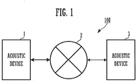
- FIG. 1 is a diagram showing a configuration of an acoustic processing system 100.
- the acoustic processing system 100 includes a plurality (two in FIG. 1 ) of acoustic devices 1 and 3 that are connected to each other through a network 2.
- the acoustic device 1 is set at a first point.
- the acoustic device 3 is set at a second point. In other words, the acoustic device 1 and the acoustic device 3 are set in places remote from each other.
- the acoustic device 1 and the acoustic device 3 are connected to a remote place through the network 2, and are used for a system that performs interactive communication between remote places.
- the acoustic device 1 and the acoustic device 3 are used for a conference system in a remote place.
- the acoustic device 1 for example, sends the voice of a user of the acoustic device 1 to a user of the acoustic device 3 through the network 2.
- the acoustic device 3 for example, sends the voice of the user of the acoustic device 3 to the user of the acoustic device 1 through the network 2.
- the user of the acoustic device 1 is referred to as a user on a near-end side.
- the user of the acoustic device 3 is referred to as a user on a far-end side.
- FIG. 2 is a block diagram showing a main configuration of the acoustic device 1. It is to be noted that the acoustic device 3 has the same configurations and the same functions as the acoustic device 1, so that the description will be omitted.
- the acoustic device 1 includes a communicating portion 11, a CPU 12, a RAM 13, a memory 14, a microphone 15, a speaker 16, and a user interface (I/F) 17.
- the communicating portion 11 configures the audio signal receiving portion of the present invention.
- the CPU 12 reads a program from the memory 14 being a storage medium and temporarily stores the program in the RAM 13, and thus performs various operations.
- the memory 14 includes a flash memory or a hard disk drive (HDD).
- the memory 14 stores programs for operating the CPU 12 as described above.
- the memory 14 stores a feature amount extraction program, a gain determination program, an audio signal reception program, and a gain adjusting program.
- the feature amount extraction program is a program to configure a voice feature amount extracting portion 51 to be described below.
- the gain determination program is a program to configure a gain determining portion 52 to be described below.
- the audio signal reception program is a program to configure an audio signal receiving portion 53 to be described below.
- the gain adjusting program is a program to configure a gain adjusting portion 54 to be described below.
- the microphone 15 obtains surrounding sound as an audio signal.
- the surrounding sound includes voice of a talker and noise.
- the microphone 15 digitally converts the obtained audio signal.
- the microphone 15 outputs the digitally converted audio signal to the CPU 12.
- the CPU 12 performs signal processing on the audio signal inputted from the microphone 15.
- the CPU 12 outputs the audio signal on which the signal processing has been performed, to the communicating portion 11.
- the acoustic device 1 may include a processor (DSP: Digital Signal Processor) exclusively used for the signal processing. In such a case, according to instructions of the CPU 12, the DSP performs signal processing.
- DSP Digital Signal Processor
- the CPU 12 outputs the audio signal on which the signal processing has been performed, to the communicating portion 11.
- the communicating portion 11 is connected to the network 2.
- the communicating portion 11 sends the audio signal to the acoustic device 3 on a far-end side through the network 2.
- the communicating portion 11 receives the audio signal from the acoustic device 3 through the network 2.
- the communicating portion 11 outputs the received audio signal to the CPU 12.
- the CPU 12 performs signal processing on the audio signal inputted from the communicating portion 11.
- the CPU 12 outputs the audio signal on which the signal processing has been performed, to the speaker 16.
- the speaker 16 emits sound based on the audio signal inputted from the CPU 12. It is to be noted that the speaker 16, when receiving an input of a digital signal, emits sound based on the audio signal after performing D/A conversion.
- the user I/F 17 receives an operation from a user.
- the operation by the user includes adjustment of the volume of a speaker, for example.
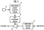
- FIG. 3 is a block diagram showing a functional configuration of the acoustic device 1.
- the acoustic device 1 includes a microphone 15, a voice feature amount extracting portion 51, a gain determining portion 52, an audio signal receiving portion 53, and a gain adjusting portion 54.
- the voice feature amount extracting portion 51, the gain determining portion 52, the gain adjusting portion 54, and the audio signal receiving portion 53 are implemented by programs of the CPU 12.
- the audio signal receiving portion 53 may be configured by the communicating portion 11.
- the voice feature amount extracting portion 51 obtains power level of an inputted audio signal.
- the power level is calculated by the root mean square of an audio signal of a time axis, for example.
- the power level is an example of the voice feature amount.
- the extraction of the voice feature amount may be performed by limiting to a predetermined band (such as an FFT band, an octave band, the Mel band, or the Bark band) .
- the voice feature amount extracting portion 51 calculates power level of 1 kHz to 4 kHz. In this manner, the extraction of the voice feature amount may be extracted in a limited band which is a great number of human voice elements. In addition, the extraction of the voice feature amount may be extracted in a plurality of bands.
- the power level of an audio signal is preferably averaged on the time axis.
- the voice feature amount extracting portion 51 by averaging the power level of an audio signal on the time axis, does not erroneously recognize noise as voice even when high noise sound is suddenly inputted.
- the gain determining portion 52 determines a gain based on the voice feature amount extracted by the voice feature amount extracting portion 51.
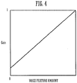
- FIG. 4 is a diagram showing the relationship between the voice feature amount and the gain. As shown in FIG. 4 , the gain determining portion 52 sets the gain higher as the power level of an audio signal is higher. The gain determining portion 52 sets the gain lower as the power level of an audio signal is lower.
- the gain determining portion 52 sets the determined gain to the gain adjusting portion 54.
- the audio signal receiving portion 53 receives an audio signal from a device on a far-end side.
- the gain adjusting portion 54 receives an input of an audio signal from the audio signal receiving portion 53, amplifies the audio signal by the set gain, and outputs the amplified audio signal to the speaker 16. In this manner, the gain determining portion 52 determines the gain of the audio signal received from a different device on a far-end side, based on the voice feature amount extracted by the voice feature amount extracting portion 51.
- the acoustic device 1 when the level of voice of a talker on a near-end side is high, causes the level of voice on a far-end side to be high as well.
- a talker talks quietly in many cases when the surrounding environment is quiet. According to the present preferred embodiment, when a talker talks quietly, sound to be outputted from the speaker 16 is also reduced. Accordingly, only the sound to be outputted from the speaker 16 is not increased. In other words, the talker does not have to manually adjust volume with caring about the surrounding environment.
- the gain determining portion 52 may average the determined gain on a time axis.
- the gain determining portion 52 suppresses a rapid change in volume by averaging a gain on a time axis, and reduces the sense of incongruity that a user feels.
- the acoustic device 1 may detect a voice section, and may adjust a gain only in the detected voice section. For example, the acoustic device 1 does not need to change a gain during a far-end single talk. In such a case, the acoustic device 1 distinguishes a far-end single talk in a case in which the audio signal receiving portion 53 receives an audio signal having a level greater than or equal to a predetermined threshold value and the power level of an audio signal inputted from the microphone 15 is less than a predetermined value.
- the acoustic device 1 may remove an echo element by the echo canceller 501.
- the echo canceller 501 generates a pseudo echo element by filtering the audio signal received from the far-end side by transfer characteristics in the environment in which the acoustic device 1 is set.
- the echo canceller 501 by subtracting the pseudo echo element from the audio signal obtained by the microphone 15, removes the echo element.
- the voice feature amount extracting portion 51 extracts a voice feature amount using the audio signal of which the echo element has been removed by the echo canceller 501. In such a case, the voice feature amount extracting portion 51 may adjust a gain during the far-end single talk.
- the echo canceller 501 may be hardware or may be achieved when the CPU 12 reads an echo cancellation program from the memory 14 and executes the program.
- FIG. 6 is a block diagram showing a functional configuration of an acoustic device 1 according to a modification.
- the same reference numerals are given to components common to the components in FIG. 3 , and the description will be omitted.
- the acoustic device 1 further includes a noise feature amount extracting portion 55.
- the noise feature amount extracting portion 55 is also achieved by the program of the CPU 12.
- the noise feature amount extracting portion 55 extracts a noise feature amount from an inputted audio signal.
- the noise feature amount extracting portion 55 obtains a noise level as an example of the noise feature amount. More specifically, the noise feature amount extracting portion 55 obtains power level of an audio signal according to noise.
- the noise feature amount extracting portion 55 in a case of determining that noise is inputted, obtains a noise level by obtaining the power level of an audio signal.
- the noise feature amount extracting portion 55 determines whether or not noise is inputted, for example, by distinguishing a near-end single talk, a far-end single talk, and a double talk.
- the noise feature amount extracting portion 55 distinguishes a far-end single talk in a case in which the audio signal receiving portion 53 receives an audio signal having a level greater than or equal to a predetermined threshold value and the power level of an audio signal inputted from the microphone 15 is less than or equal to a predetermined value.
- the noise feature amount extracting portion 55 distinguishes a double talk in a case in which the audio signal receiving portion 53 receives an audio signal having a level greater than or equal to a predetermined threshold value and the power level of an audio signal inputted from the microphone 15 is greater than or equal to a predetermined value.
- the noise feature amount extracting portion 55 distinguishes a near-end single talk in a case in which the audio signal receiving portion 53 receives an audio signal having a level less than a predetermined threshold value and the power level of an audio signal inputted from the microphone 15 is greater than or equal to a predetermined value.
- the noise feature amount extracting portion 55 calculates a noise feature amount in a case of no correspondence to a near-end single talk, a far-end single talk, and a double talk. More specifically, the noise feature amount extracting portion 55 obtains the power level of the inputted audio signal as a noise feature amount in a case in which the audio signal receiving portion 53 receives an audio signal having a level less than a predetermined threshold value and the power level of an audio signal inputted from the microphone 15 is less than or equal to a predetermined value.
- the noise feature amount extracting portion 55 in a case of removing an echo element by the echo canceller 501, may set the power level of an audio signal inputted during a far-end single talk as a noise feature amount. It is to be noted that the noise feature amount may be averaged on a time axis.
- the voice feature amount extracting portion 51 may perform noise cancellation processing based on the noise feature amount extracted by the noise feature amount extracting portion 55. For example, the voice feature amount extracting portion 51 subtracts the power level of an audio signal that the noise feature amount extracting portion 55 has obtained, from the voice feature amount. As a result, the voice feature amount extracting portion 51 is able to obtain the power level of an audio signal according to voice with higher accuracy, based on the audio signal of which the noise sound has been removed.
- the gain determining portion 52 determines a gain, based on the voice feature amount and the noise feature amount that have been extracted by the voice feature amount extracting portion 51 and the noise feature amount extracting portion 55.
- FIG. 7 is a diagram showing the relationship between the voice feature amount and the gain. As shown in FIG. 7 , the gain determining portion 52 sets the gain higher as the voice feature amount is higher. The gain determining portion 52 sets the gain lower as the voice feature amount is lower. Furthermore, the gain determining portion 52 sets the gain higher as the noise feature amount is higher. The gain determining portion 52 sets the gain lower as the noise feature amount is lower.
- the acoustic device 1 when the level of voice of a talker on a near-end side is high and the noise level is low, causes the level of voice on a far-end side to be low.
- the acoustic device 1 when the level of the voice of the talker on a near-end side is low and the noise level is high, causes the level of the voice on a far-end side to be high.
- the modification even when the voice of a talker is loud, sound to be outputted from the speaker 16 is reduced when the surrounding environment is quiet. Accordingly, only the sound to be outputted from the speaker 16 is not increased. In other words, the talker does not have to manually adjust the volume with caring about the surrounding environment.
- the noise feature amount extracting portion 55 may further detect distant noise. Accordingly, the acoustic device 1, even when a talker other than a user is in a position away from the acoustic device 1, reduces a possibility of erroneously recognizing the voice of a talker on a near-end side.
- FIG. 8 is a diagram showing a functional configuration of the acoustic device 1 in a case of detecting distant noise.
- the acoustic device 1 further includes a second microphone 15B and a correlation calculating portion 57 in addition to the configuration of FIG. 7 .
- the correlation calculating portion 57 receives an input of an audio signal from the microphone 15 and the microphone 15B.
- the correlation calculating portion 57 calculates a correlation of two audio signals.
- the correlation is calculated, for example, by cross-power level spectrum phase analysis.
- Distant sound includes a large number of indirect sound elements, and is a sound of which an arrival direction is not fixed.
- the microphone 15 has a directivity and the microphone 15B has a non-directivity
- sound collection capability with respect to distant sound is greatly different. Therefore, the correlation is reduced in a case of sound from a distant sound source, and is increased in a case of sound from a sound source near the device.
- the noise feature amount extracting portion 55 when the correlation calculated by the correlation calculating portion 57 is small, distinguishes that sound from the distant sound source has been detected, and sets the power level of the inputted audio signal as a noise feature amount.
- the voice feature amount extracting portion 51 in a case in which the correlation calculated by the correlation calculating portion 57 is large, distinguishes that voice of a talker has been detected, and sets the power level of the inputted audio signal as a voice feature amount. Accordingly, the acoustic device 1 is able to obtain the noise feature amount and the voice feature amount with higher accuracy.
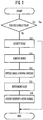
- FIG. 9 is a flow chart showing an operation of an acoustic device 1 according to a first modification.
- the acoustic device 1 first distinguishes a near-end single talk, a far-end single talk, and a double talk. In other words, the acoustic device 1 distinguishes whether or not a far-end single talk is performed (S11).
- the acoustic device 1 in a case of distinguishing a far-end single talk (S11: Yes), ends the processing. In other words, the acoustic device 1 does not change a gain.
- the acoustic device 1 in a case that a far-end single talk is not performed (in a case of a near-end single talk or a double talk) (S11: No), detects background noise from the inputted audio signal (S12).
- the acoustic device 1 obtains power level of an audio signal according to the detected background noise, and reduces a noise element from the audio signal (S13). Subsequently, the acoustic device 1 obtains the power level of the inputted audio signal as a noise feature amount (S14). Finally, the acoustic device 1 determines a gain of the audio signal received from the far-end side, based on a voice feature amount and the noise feature amount (S15) and adjusts a level of the received audio signal by the gain (S16).
- the processing of S11, S12, and S14 is not required in the present invention.
- the acoustic device 1, in S13 may determine a gain, based on the voice feature amount extracted by the voice feature amount extracting portion 51, without using the noise feature amount.
- the acoustic device may determine a gain, based on the noise feature amount extracted by the noise feature amount extracting portion 55, without using the voice feature amount. For example, the acoustic device 1 increases a gain when the power level of a noise signal is high. In other words, the acoustic device according to the first preferred embodiment may extract a feature amount from the sound collected by a microphone, and may determine a gain of an audio signal received from a different device on a far-end side, based on the extracted feature amount.
- An acoustic device includes microphone, a noise level obtaining portion that obtains a noise level from sound collected by the microphone, a storage in which a predetermined noise level is stored, an audio signal receiving portion that receives an audio signal from a different device on a far-end side, and a gain determining portion that determines a gain of the audio signal received from the different device on the far-end side, based on the predetermined noise level and a present noise level obtained by the noise level obtaining portion.
- the acoustic device determines a level of the audio signal on the far-end side, based on a previously stored noise level and the present noise level.
- the volume of a speaker with respect to the noise level as a reference is automatically determined, so that a user on a near-end side has no difficulty hearing.
- the acoustic device reduces the level of the voice on a far-end side, when the present noise level reduces with respect to the noise level as a reference. Accordingly, only the sound to be outputted from the speaker 16 is not increased. In other words, the talker does not have to manually adjust the volume with caring about the surrounding environment.
- the storage stores the noise level obtained by the noise level obtaining portion.
- the gain determining portion determines a gain of the audio signal received from the different device on a far-end side, based on a previous noise level stored in the storage and the present noise level obtained by the noise level obtaining portion.
- the acoustic device obtains noise around the device and determines the volume of a speaker, based on the level of the obtained noise sound. Therefore, the acoustic device is able to adjust the volume of a speaker according to a more nearly actual environment.
- the acoustic device may include a volume adjustment receiving portion that receives volume adjustment from a user.
- the storage may store a noise level when the user adjusts the volume.
- the acoustic device determines the volume of a speaker, on a basis of a ratio between the noise level and the volume of a speaker that the user manually adjusted. Accordingly, the volume of a speaker is automatically adjusted to a volume that the user feels appropriate.
- the acoustic device may include a distinguishing portion that distinguishes a voice section, and the gain determining portion may determine a gain in the voice section that the distinguishing portion has distinguished.
- the acoustic device since performing in a limited(in a each of distinguished) voice section, is able to determine a gain with higher accuracy.
- FIG. 10 is a block diagram showing a functional configuration of the acoustic device 1A.
- the same reference numerals are given to components common to the components of the acoustic device 1 according to the first preferred embodiment in FIG. 6 , and the description will be omitted.
- the acoustic device 1A further includes a volume adjustment receiving portion 71, and a storage 72 that stores a noise feature amount that the noise feature amount extracting portion 55 has extracted.
- the hardware configuration of the acoustic device 1A is the same as the hardware configuration shown in FIG. 2 .
- the storage 72 is configured by the memory 14.
- the volume adjustment receiving portion 71 is configured by the user I/F 17.
- the volume adjustment receiving portion 71 may be implemented when the CPU 12 reads and executes a volume adjustment receive program stored in the memory 14.
- the volume adjustment receiving portion 71 receives an operation of volume adjustment from a user.
- the volume adjustment receiving portion 71 adjusts the gain of the gain adjusting portion 54, based on the operation of the received volume adjustment.
- the noise feature amount extracting portion 55 is an example of the noise level obtaining portion.
- the noise feature amount extracting portion 55 is configured by the feature amount extraction program.
- the noise feature amount extracting portion 55 obtains a noise feature amount.
- the way to obtain the noise feature amount is the same as the way of the first preferred embodiment, and, for example, obtains a noise level.
- the noise feature amount extracting portion 55 outputs a noise level to the storage 72 when the volume adjustment receiving portion 71 receives the operation of volume adjustment.
- the storage 72 stores the noise level when a user adjust the volume.
- the noise feature amount extracting portion 55 outputs the noise level to the gain determining portion 52.
- the gain determining portion 52 determines a gain, based on the previous noise level stored in the storage 72 and the present noise level outputted from the noise feature amount extracting portion 55. For example, the gain determining portion 52, in a case in which the present noise level is higher than the previous noise level, increases the gain. Accordingly, the volume of a speaker with respect to the noise level as a reference is automatically determined.
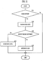
- FIG. 11 is a flow chart showing an operation of the acoustic device 1A.
- the acoustic device 1A first distinguishes whether or not a noise section is present (S101). As shown in FIG. 11 , the acoustic device 1A distinguishes the noise section in a case in which a status is not any of a near-end single talk, a far-end single talk, and a double talk.
- the acoustic device 1A in a case of distinguishing a near-end single talk, a far-end single talk, or a double talk (S101: No), ends the processing. In other words, the acoustic device 1A does not perform a gain adjustment when a noise section is not present.
- the acoustic device 1A in a case of removing an echo element by the echo canceller 501, may distinguish a far-end single talk as a noise section.
- the acoustic device 1A in a case of distinguishing a noise section (S101: Yes), obtains a noise level, for example, as a noise feature amount (S102). Subsequently, the acoustic device 1A determines whether or not volume adjustment has been received from a user (S103). The acoustic device 1A, in a case of receiving the volume adjustment from a user (S103: Yes), stores the obtained noise level (S104). The acoustic device 1A, in a case of receiving no volume adjustment (S103: No), determines a gain, based on the stored previous noise level and the obtained present noise level (S105). For example, the acoustic device 1A, in the case in which the present noise level is higher than the previous noise level, increases the gain. Accordingly, the volume of a speaker with respect to the noise level as a reference is automatically determined.
- a gain adjustment may be performed to all the bands or may be performed in a limiting predetermined band (such as an FFT band, an octave band, the Mel band, or the Bark band).
- the voice feature amount extracting portion 51 may perform a gain adjustment in a band of 1 kHz to 4 kHz that has a significant effect on the sensitivity of voice.
- the acoustic device 1A may perform a gain adjustment, based on the obtained noise feature amount. For example, the acoustic device 1A performs a gain adjustment according to a noise spectrum. The acoustic device 1A sets a gain high in a band in which a noise level is high. Accordingly, surrounding people except a user are less likely to feel noisy about the sound outputted from the speaker 16.
- the acoustic device 1A may perform a gain adjustment according to human auditory characteristics (loudness characteristics). For example, low-frequency and high-frequency gains do not greatly change regardless of a change in noise level.
- the voice feature amount is not limited to power level.
- the acoustic device 1 may calculate the peak of a low frequency element of a cepstrum obtained by further applying the Fourier transform to the spectrum of an audio signal.
- the acoustic device 1 may normalize a peak value of the low frequency element of a cepstrum, may convert the value into a value of 0 to 1, and may extract the value as a voice feature amount.
- the noise feature amount is not limited to power level.
- the storage does not need to be built in the acoustic device 1A.
- the storage may be provided in a server. In such a case, the acoustic device 1A obtains a noise level from the storage of the server.
- the acoustic device 1 or the acoustic device 1A may include a feature amount extraction circuit 51A corresponding to the voice feature amount extracting portion 51 or the noise feature amount extracting portion 55, a gain determination circuit 52A corresponding to the gain determining portion 52, an audio signal reception circuit 53A corresponding to the audio signal receiving portion 53, and a gain adjusting circuit 54A corresponding to the gain adjusting portion 54.
- the configuration of the present invention may be implemented by appropriately combining hardware and software.
Landscapes
- Engineering & Computer Science (AREA)
- Multimedia (AREA)
- Health & Medical Sciences (AREA)
- Audiology, Speech & Language Pathology (AREA)
- Human Computer Interaction (AREA)
- Physics & Mathematics (AREA)
- Signal Processing (AREA)
- Acoustics & Sound (AREA)
- Computational Linguistics (AREA)
- Quality & Reliability (AREA)
- Theoretical Computer Science (AREA)
- General Health & Medical Sciences (AREA)
- General Physics & Mathematics (AREA)
- General Engineering & Computer Science (AREA)
- Circuit For Audible Band Transducer (AREA)
- Telephone Function (AREA)
- Cable Transmission Systems, Equalization Of Radio And Reduction Of Echo (AREA)
Abstract
Description
- A preferred embodiment of the present invention relates to an acoustic device and an acoustic processing method.
- Japanese Unexamined Patent Application Publication No.
2004-20733 - Japanese Utility Model Application Publication No.
H07-039114 - Both of Japanese Unexamined Patent Application Publication No.
2004-20733 H07-039114 2004-20733 H07-039114 - In view of the foregoing, an object of a preferred embodiment of the present invention is to provide an acoustic device and an acoustic processing method that adjust an audio signal received from a far-end side to an appropriate level.
- An acoustic device includes a microphone, a feature amount extracting portion that extracts a feature amount from a first audio signal representing sound collected by a microphone, an audio signal receiving portion that receives a second audio signal from a different device on a far-end side, a gain determining portion that determines a gain of the second audio signal based on the extracted feature amount, and a gain adjusting portion the second audio signal based on the determined gain of the second audio signal.
-
-
FIG. 1 is a block diagram showing a configuration of an acoustic system. -
FIG. 2 is a block diagram showing a main configuration of an acoustic device 1. -
FIG. 3 is a block diagram showing a functional configuration of the acoustic device 1. -
FIG. 4 is a diagram showing the relationship between a voice feature amount and a gain. -
FIG. 5 is a block diagram showing a functional configuration of the acoustic device 1 including an echo canceler. -
FIG. 6 a block diagram showing a functional configuration of an acoustic device 1 according to a modification. -
FIG. 7 is a diagram showing the relationship between a voice feature amount and a gain. -
FIG. 8 is a diagram showing a functional configuration of the acoustic device 1 in a case of detecting distant noise. -
FIG. 9 is a flow chart showing an operation of an acoustic device 1 according to a first modification. -
FIG. 10 is a block diagram showing a functional configuration of anacoustic device 1A. -
FIG. 11 is a flow chart showing an operation of theacoustic device 1A. -
FIG. 12 is a block diagram showing a main configuration of theacoustic device 1, 1A. - An acoustic device according to a first preferred embodiment includes a microphone, a voice feature amount extracting portion that extracts a voice feature amount from sound (corresponding to a first audio signal of the present invention) collected by the microphone, an audio signal receiving portion that receives an audio signal (corresponding to a second audio signal of the present invention) from a different device on a far-end side, and a gain determining portion that determines a gain of the audio signal received from the different device on the far-end side, based on the voice feature amount that has been extracted by the voice feature amount extracting portion.
- The voice feature amount includes power level of an audio signal, for example. The acoustic device according to the first preferred embodiment determines a level of voice of a talker on a far-end side, according to voice of a talker on a near-end side. As an example, the talker on a near-end side talks loudly when a surrounding noise level is high. At this time, when the level of the voice of the talker on a far-end side is low, a user on a near-end side has difficulty hearing the voice of the talker on a far-end side. Therefore, as an example, the acoustic device, when the level of the voice of the talker on a near-end side is high, causes the level of the voice on a far-end side to be high. Accordingly, the acoustic device is able to output the voice received from the far-end side at an appropriate volume.
- The acoustic device according to the first preferred embodiment includes a noise feature amount obtaining portion that obtains a noise feature amount from sound collected by a microphone. The gain determining portion determines a gain, based on a voice feature amount and a noise feature amount.
- The noise feature amount includes power level of a noise signal, for example. In such a case, the acoustic device determines the level of the voice of a far-end side, further according to the noise on a near-end side. For example, when the volume of noise is low, even if the level of the voice of the talker on a far-end side is reduced, the user on a near-end side has no difficulty hearing. Therefore, the acoustic device reduces the level of the voice of the talker on a far-end side, when the level of the voice of the talker on a near-end side is high and the level of noise is low.
- It is to be noted that the acoustic device includes an echo canceller that removes an echo element from the sound collected by the microphone. The noise feature amount obtaining portion may obtain a noise feature amount from the sound of which the echo element has been removed by the echo canceller.
- The acoustic device does not erroneously recognize the voice on a far-end side as noise by removing an echo element. Therefore, the acoustic device is able to obtain a noise feature amount with higher accuracy.
- It is to be noted that the acoustic device may include a distinguishing portion that distinguishes a voice section, and the gain determining portion may determine a gain in the voice section that the distinguishing portion has distinguished. The acoustic device, since performing in a limited (in a each of a distinguished) voice section, is able to determine a gain with higher accuracy.
- Hereinafter, the acoustic device according to the first preferred embodiment will be described in more detail.
FIG. 1 is a diagram showing a configuration of anacoustic processing system 100. Theacoustic processing system 100 includes a plurality (two inFIG. 1 ) ofacoustic devices 1 and 3 that are connected to each other through a network 2. - The acoustic device 1 is set at a first point. The
acoustic device 3 is set at a second point. In other words, the acoustic device 1 and theacoustic device 3 are set in places remote from each other. - The acoustic device 1 and the
acoustic device 3 are connected to a remote place through the network 2, and are used for a system that performs interactive communication between remote places. For example, the acoustic device 1 and theacoustic device 3 are used for a conference system in a remote place. The acoustic device 1, for example, sends the voice of a user of the acoustic device 1 to a user of theacoustic device 3 through the network 2. In addition, theacoustic device 3, for example, sends the voice of the user of theacoustic device 3 to the user of the acoustic device 1 through the network 2. - In the following description, the user of the acoustic device 1 is referred to as a user on a near-end side. In addition, in the following description, the user of the
acoustic device 3 is referred to as a user on a far-end side. -
FIG. 2 is a block diagram showing a main configuration of the acoustic device 1. It is to be noted that theacoustic device 3 has the same configurations and the same functions as the acoustic device 1, so that the description will be omitted. - The acoustic device 1 includes a communicating
portion 11, aCPU 12, aRAM 13, amemory 14, amicrophone 15, aspeaker 16, and a user interface (I/F) 17. The communicatingportion 11 configures the audio signal receiving portion of the present invention. - The
CPU 12 reads a program from thememory 14 being a storage medium and temporarily stores the program in theRAM 13, and thus performs various operations. - The
memory 14 includes a flash memory or a hard disk drive (HDD). Thememory 14 stores programs for operating theCPU 12 as described above. In addition, thememory 14 stores a feature amount extraction program, a gain determination program, an audio signal reception program, and a gain adjusting program. The feature amount extraction program is a program to configure a voice featureamount extracting portion 51 to be described below. The gain determination program is a program to configure again determining portion 52 to be described below. The audio signal reception program is a program to configure an audiosignal receiving portion 53 to be described below. The gain adjusting program is a program to configure again adjusting portion 54 to be described below. - The
microphone 15 obtains surrounding sound as an audio signal. The surrounding sound includes voice of a talker and noise. Themicrophone 15 digitally converts the obtained audio signal. Themicrophone 15 outputs the digitally converted audio signal to theCPU 12. - The
CPU 12 performs signal processing on the audio signal inputted from themicrophone 15. TheCPU 12 outputs the audio signal on which the signal processing has been performed, to the communicatingportion 11. It is to be noted that the acoustic device 1 may include a processor (DSP: Digital Signal Processor) exclusively used for the signal processing. In such a case, according to instructions of theCPU 12, the DSP performs signal processing. - The
CPU 12 outputs the audio signal on which the signal processing has been performed, to the communicatingportion 11. The communicatingportion 11 is connected to the network 2. The communicatingportion 11 sends the audio signal to theacoustic device 3 on a far-end side through the network 2. - In addition, the communicating
portion 11 receives the audio signal from theacoustic device 3 through the network 2. The communicatingportion 11 outputs the received audio signal to theCPU 12. TheCPU 12 performs signal processing on the audio signal inputted from the communicatingportion 11. TheCPU 12 outputs the audio signal on which the signal processing has been performed, to thespeaker 16. - The
speaker 16 emits sound based on the audio signal inputted from theCPU 12. It is to be noted that thespeaker 16, when receiving an input of a digital signal, emits sound based on the audio signal after performing D/A conversion. - The user I/
F 17 receives an operation from a user. The operation by the user includes adjustment of the volume of a speaker, for example. -
FIG. 3 is a block diagram showing a functional configuration of the acoustic device 1. The acoustic device 1, as a functional configuration, includes amicrophone 15, a voice featureamount extracting portion 51, again determining portion 52, an audiosignal receiving portion 53, and again adjusting portion 54. - The voice feature
amount extracting portion 51, thegain determining portion 52, thegain adjusting portion 54, and the audiosignal receiving portion 53 are implemented by programs of theCPU 12. The audiosignal receiving portion 53 may be configured by the communicatingportion 11. - The voice feature
amount extracting portion 51 obtains power level of an inputted audio signal. The power level is calculated by the root mean square of an audio signal of a time axis, for example. The power level is an example of the voice feature amount. The extraction of the voice feature amount may be performed by limiting to a predetermined band (such as an FFT band, an octave band, the Mel band, or the Bark band) . For example, the voice featureamount extracting portion 51 calculates power level of 1 kHz to 4 kHz. In this manner, the extraction of the voice feature amount may be extracted in a limited band which is a great number of human voice elements. In addition, the extraction of the voice feature amount may be extracted in a plurality of bands. - It is to be noted that the power level of an audio signal is preferably averaged on the time axis. The voice feature
amount extracting portion 51, by averaging the power level of an audio signal on the time axis, does not erroneously recognize noise as voice even when high noise sound is suddenly inputted. - The
gain determining portion 52 determines a gain based on the voice feature amount extracted by the voice featureamount extracting portion 51.FIG. 4 is a diagram showing the relationship between the voice feature amount and the gain. As shown inFIG. 4 , thegain determining portion 52 sets the gain higher as the power level of an audio signal is higher. Thegain determining portion 52 sets the gain lower as the power level of an audio signal is lower. - The
gain determining portion 52 sets the determined gain to thegain adjusting portion 54. The audiosignal receiving portion 53 receives an audio signal from a device on a far-end side. Thegain adjusting portion 54 receives an input of an audio signal from the audiosignal receiving portion 53, amplifies the audio signal by the set gain, and outputs the amplified audio signal to thespeaker 16. In this manner, thegain determining portion 52 determines the gain of the audio signal received from a different device on a far-end side, based on the voice feature amount extracted by the voice featureamount extracting portion 51. - Therefore, the acoustic device 1, when the level of voice of a talker on a near-end side is high, causes the level of voice on a far-end side to be high as well. The acoustic device 1, when the level of the voice of the talker on a near-end side is low, causes the level of the voice on a far-end side to be low as well. A talker talks quietly in many cases when the surrounding environment is quiet. According to the present preferred embodiment, when a talker talks quietly, sound to be outputted from the
speaker 16 is also reduced. Accordingly, only the sound to be outputted from thespeaker 16 is not increased. In other words, the talker does not have to manually adjust volume with caring about the surrounding environment. - It is to be noted that the
gain determining portion 52 may average the determined gain on a time axis. Thegain determining portion 52 suppresses a rapid change in volume by averaging a gain on a time axis, and reduces the sense of incongruity that a user feels. - In addition, the acoustic device 1 may detect a voice section, and may adjust a gain only in the detected voice section. For example, the acoustic device 1 does not need to change a gain during a far-end single talk. In such a case, the acoustic device 1 distinguishes a far-end single talk in a case in which the audio
signal receiving portion 53 receives an audio signal having a level greater than or equal to a predetermined threshold value and the power level of an audio signal inputted from themicrophone 15 is less than a predetermined value. - In addition, the acoustic device 1, as shown in
FIG. 5 , may remove an echo element by theecho canceller 501. Theecho canceller 501 generates a pseudo echo element by filtering the audio signal received from the far-end side by transfer characteristics in the environment in which the acoustic device 1 is set. Theecho canceller 501, by subtracting the pseudo echo element from the audio signal obtained by themicrophone 15, removes the echo element. The voice featureamount extracting portion 51 extracts a voice feature amount using the audio signal of which the echo element has been removed by theecho canceller 501. In such a case, the voice featureamount extracting portion 51 may adjust a gain during the far-end single talk. It is to be noted that theecho canceller 501 may be hardware or may be achieved when theCPU 12 reads an echo cancellation program from thememory 14 and executes the program. - Next,
FIG. 6 is a block diagram showing a functional configuration of an acoustic device 1 according to a modification. The same reference numerals are given to components common to the components inFIG. 3 , and the description will be omitted. The acoustic device 1 further includes a noise featureamount extracting portion 55. The noise featureamount extracting portion 55 is also achieved by the program of theCPU 12. - The noise feature
amount extracting portion 55 extracts a noise feature amount from an inputted audio signal. The noise featureamount extracting portion 55 obtains a noise level as an example of the noise feature amount. More specifically, the noise featureamount extracting portion 55 obtains power level of an audio signal according to noise. - The noise feature
amount extracting portion 55, in a case of determining that noise is inputted, obtains a noise level by obtaining the power level of an audio signal. The noise featureamount extracting portion 55 determines whether or not noise is inputted, for example, by distinguishing a near-end single talk, a far-end single talk, and a double talk. The noise featureamount extracting portion 55 distinguishes a far-end single talk in a case in which the audiosignal receiving portion 53 receives an audio signal having a level greater than or equal to a predetermined threshold value and the power level of an audio signal inputted from themicrophone 15 is less than or equal to a predetermined value. The noise featureamount extracting portion 55 distinguishes a double talk in a case in which the audiosignal receiving portion 53 receives an audio signal having a level greater than or equal to a predetermined threshold value and the power level of an audio signal inputted from themicrophone 15 is greater than or equal to a predetermined value. The noise featureamount extracting portion 55 distinguishes a near-end single talk in a case in which the audiosignal receiving portion 53 receives an audio signal having a level less than a predetermined threshold value and the power level of an audio signal inputted from themicrophone 15 is greater than or equal to a predetermined value. - The noise feature
amount extracting portion 55 calculates a noise feature amount in a case of no correspondence to a near-end single talk, a far-end single talk, and a double talk. More specifically, the noise featureamount extracting portion 55 obtains the power level of the inputted audio signal as a noise feature amount in a case in which the audiosignal receiving portion 53 receives an audio signal having a level less than a predetermined threshold value and the power level of an audio signal inputted from themicrophone 15 is less than or equal to a predetermined value. However, the noise featureamount extracting portion 55, in a case of removing an echo element by theecho canceller 501, may set the power level of an audio signal inputted during a far-end single talk as a noise feature amount. It is to be noted that the noise feature amount may be averaged on a time axis. - It is to be noted that the voice feature
amount extracting portion 51 may perform noise cancellation processing based on the noise feature amount extracted by the noise featureamount extracting portion 55. For example, the voice featureamount extracting portion 51 subtracts the power level of an audio signal that the noise featureamount extracting portion 55 has obtained, from the voice feature amount. As a result, the voice featureamount extracting portion 51 is able to obtain the power level of an audio signal according to voice with higher accuracy, based on the audio signal of which the noise sound has been removed. - The
gain determining portion 52 determines a gain, based on the voice feature amount and the noise feature amount that have been extracted by the voice featureamount extracting portion 51 and the noise featureamount extracting portion 55.FIG. 7 is a diagram showing the relationship between the voice feature amount and the gain. As shown inFIG. 7 , thegain determining portion 52 sets the gain higher as the voice feature amount is higher. Thegain determining portion 52 sets the gain lower as the voice feature amount is lower. Furthermore, thegain determining portion 52 sets the gain higher as the noise feature amount is higher. Thegain determining portion 52 sets the gain lower as the noise feature amount is lower. - Therefore, the acoustic device 1 according to a modification, when the level of voice of a talker on a near-end side is high and the noise level is low, causes the level of voice on a far-end side to be low. The acoustic device 1, when the level of the voice of the talker on a near-end side is low and the noise level is high, causes the level of the voice on a far-end side to be high. According to the modification, even when the voice of a talker is loud, sound to be outputted from the
speaker 16 is reduced when the surrounding environment is quiet. Accordingly, only the sound to be outputted from thespeaker 16 is not increased. In other words, the talker does not have to manually adjust the volume with caring about the surrounding environment. In addition, according to the modification, even when the voice of a talker is quiet, sound to be outputted from thespeaker 16 is increased when the surrounding environment is noisy. Accordingly, only the sound to be outputted from thespeaker 16 is not reduced. In other words, a talker, even when talking in a quiet voice in a noisy environment, can hear voice on the far-end side. - It is to be noted that the noise feature
amount extracting portion 55 may further detect distant noise. Accordingly, the acoustic device 1, even when a talker other than a user is in a position away from the acoustic device 1, reduces a possibility of erroneously recognizing the voice of a talker on a near-end side. -
FIG. 8 is a diagram showing a functional configuration of the acoustic device 1 in a case of detecting distant noise. The acoustic device 1 further includes asecond microphone 15B and acorrelation calculating portion 57 in addition to the configuration ofFIG. 7 . - The
correlation calculating portion 57 receives an input of an audio signal from themicrophone 15 and themicrophone 15B. Thecorrelation calculating portion 57 calculates a correlation of two audio signals. The correlation is calculated, for example, by cross-power level spectrum phase analysis. - Distant sound includes a large number of indirect sound elements, and is a sound of which an arrival direction is not fixed. For example, in a case in which the
microphone 15 has a directivity and themicrophone 15B has a non-directivity, sound collection capability with respect to distant sound is greatly different. Therefore, the correlation is reduced in a case of sound from a distant sound source, and is increased in a case of sound from a sound source near the device. - The noise feature
amount extracting portion 55, when the correlation calculated by thecorrelation calculating portion 57 is small, distinguishes that sound from the distant sound source has been detected, and sets the power level of the inputted audio signal as a noise feature amount. The voice featureamount extracting portion 51, in a case in which the correlation calculated by thecorrelation calculating portion 57 is large, distinguishes that voice of a talker has been detected, and sets the power level of the inputted audio signal as a voice feature amount. Accordingly, the acoustic device 1 is able to obtain the noise feature amount and the voice feature amount with higher accuracy. -
FIG. 9 is a flow chart showing an operation of an acoustic device 1 according to a first modification. The acoustic device 1 first distinguishes a near-end single talk, a far-end single talk, and a double talk. In other words, the acoustic device 1 distinguishes whether or not a far-end single talk is performed (S11). - The acoustic device 1, in a case of distinguishing a far-end single talk (S11: Yes), ends the processing. In other words, the acoustic device 1 does not change a gain.
- The acoustic device 1, in a case that a far-end single talk is not performed (in a case of a near-end single talk or a double talk) (S11: No), detects background noise from the inputted audio signal (S12).
- The acoustic device 1 obtains power level of an audio signal according to the detected background noise, and reduces a noise element from the audio signal (S13). Subsequently, the acoustic device 1 obtains the power level of the inputted audio signal as a noise feature amount (S14). Finally, the acoustic device 1 determines a gain of the audio signal received from the far-end side, based on a voice feature amount and the noise feature amount (S15) and adjusts a level of the received audio signal by the gain (S16).
- The processing of S11, S12, and S14 is not required in the present invention. The acoustic device 1, in S13, may determine a gain, based on the voice feature amount extracted by the voice feature
amount extracting portion 51, without using the noise feature amount. - It is to be noted that the acoustic device according to the first preferred embodiment may determine a gain, based on the noise feature amount extracted by the noise feature
amount extracting portion 55, without using the voice feature amount. For example, the acoustic device 1 increases a gain when the power level of a noise signal is high. In other words, the acoustic device according to the first preferred embodiment may extract a feature amount from the sound collected by a microphone, and may determine a gain of an audio signal received from a different device on a far-end side, based on the extracted feature amount. - An acoustic device according to a second preferred embodiment includes microphone, a noise level obtaining portion that obtains a noise level from sound collected by the microphone, a storage in which a predetermined noise level is stored, an audio signal receiving portion that receives an audio signal from a different device on a far-end side, and a gain determining portion that determines a gain of the audio signal received from the different device on the far-end side, based on the predetermined noise level and a present noise level obtained by the noise level obtaining portion.
- The acoustic device according to the second preferred embodiment determines a level of the audio signal on the far-end side, based on a previously stored noise level and the present noise level. In the acoustic device according to the second preferred embodiment, the volume of a speaker with respect to the noise level as a reference is automatically determined, so that a user on a near-end side has no difficulty hearing. In addition, the acoustic device reduces the level of the voice on a far-end side, when the present noise level reduces with respect to the noise level as a reference. Accordingly, only the sound to be outputted from the
speaker 16 is not increased. In other words, the talker does not have to manually adjust the volume with caring about the surrounding environment. - More preferably, the storage stores the noise level obtained by the noise level obtaining portion. The gain determining portion determines a gain of the audio signal received from the different device on a far-end side, based on a previous noise level stored in the storage and the present noise level obtained by the noise level obtaining portion.
- In such a case, the acoustic device obtains noise around the device and determines the volume of a speaker, based on the level of the obtained noise sound. Therefore, the acoustic device is able to adjust the volume of a speaker according to a more nearly actual environment.
- In addition, the acoustic device may include a volume adjustment receiving portion that receives volume adjustment from a user. The storage may store a noise level when the user adjusts the volume.
- In such a case, the acoustic device determines the volume of a speaker, on a basis of a ratio between the noise level and the volume of a speaker that the user manually adjusted. Accordingly, the volume of a speaker is automatically adjusted to a volume that the user feels appropriate.
- It is to be noted that the acoustic device may include a distinguishing portion that distinguishes a voice section, and the gain determining portion may determine a gain in the voice section that the distinguishing portion has distinguished. The acoustic device, since performing in a limited(in a each of distinguished) voice section, is able to determine a gain with higher accuracy.
- Hereinafter, an
acoustic device 1A according to the second preferred embodiment will be described in more detail.FIG. 10 is a block diagram showing a functional configuration of theacoustic device 1A. The same reference numerals are given to components common to the components of the acoustic device 1 according to the first preferred embodiment inFIG. 6 , and the description will be omitted. - The
acoustic device 1A further includes a volumeadjustment receiving portion 71, and astorage 72 that stores a noise feature amount that the noise featureamount extracting portion 55 has extracted. The hardware configuration of theacoustic device 1A is the same as the hardware configuration shown inFIG. 2 . Thestorage 72 is configured by thememory 14. The volumeadjustment receiving portion 71 is configured by the user I/F 17. The volumeadjustment receiving portion 71 may be implemented when theCPU 12 reads and executes a volume adjustment receive program stored in thememory 14. - The volume
adjustment receiving portion 71 receives an operation of volume adjustment from a user. The volumeadjustment receiving portion 71 adjusts the gain of thegain adjusting portion 54, based on the operation of the received volume adjustment. - The noise feature
amount extracting portion 55 is an example of the noise level obtaining portion. The noise featureamount extracting portion 55 is configured by the feature amount extraction program. The noise featureamount extracting portion 55 obtains a noise feature amount. The way to obtain the noise feature amount is the same as the way of the first preferred embodiment, and, for example, obtains a noise level. The noise featureamount extracting portion 55 outputs a noise level to thestorage 72 when the volumeadjustment receiving portion 71 receives the operation of volume adjustment. Thestorage 72 stores the noise level when a user adjust the volume. The noise featureamount extracting portion 55 outputs the noise level to thegain determining portion 52. Thegain determining portion 52 determines a gain, based on the previous noise level stored in thestorage 72 and the present noise level outputted from the noise featureamount extracting portion 55. For example, thegain determining portion 52, in a case in which the present noise level is higher than the previous noise level, increases the gain. Accordingly, the volume of a speaker with respect to the noise level as a reference is automatically determined. -
FIG. 11 is a flow chart showing an operation of theacoustic device 1A. Theacoustic device 1A first distinguishes whether or not a noise section is present (S101). As shown inFIG. 11 , theacoustic device 1A distinguishes the noise section in a case in which a status is not any of a near-end single talk, a far-end single talk, and a double talk. Theacoustic device 1A, in a case of distinguishing a near-end single talk, a far-end single talk, or a double talk (S101: No), ends the processing. In other words, theacoustic device 1A does not perform a gain adjustment when a noise section is not present. - It is to be noted that the
acoustic device 1A, in a case of removing an echo element by theecho canceller 501, may distinguish a far-end single talk as a noise section. - The
acoustic device 1A, in a case of distinguishing a noise section (S101: Yes), obtains a noise level, for example, as a noise feature amount (S102). Subsequently, theacoustic device 1A determines whether or not volume adjustment has been received from a user (S103). Theacoustic device 1A, in a case of receiving the volume adjustment from a user (S103: Yes), stores the obtained noise level (S104). Theacoustic device 1A, in a case of receiving no volume adjustment (S103: No), determines a gain, based on the stored previous noise level and the obtained present noise level (S105). For example, theacoustic device 1A, in the case in which the present noise level is higher than the previous noise level, increases the gain. Accordingly, the volume of a speaker with respect to the noise level as a reference is automatically determined. - It is to be noted that a gain adjustment may be performed to all the bands or may be performed in a limiting predetermined band (such as an FFT band, an octave band, the Mel band, or the Bark band). For example, the voice feature
amount extracting portion 51 may perform a gain adjustment in a band of 1 kHz to 4 kHz that has a significant effect on the sensitivity of voice. - In addition, the
acoustic device 1A may perform a gain adjustment, based on the obtained noise feature amount. For example, theacoustic device 1A performs a gain adjustment according to a noise spectrum. Theacoustic device 1A sets a gain high in a band in which a noise level is high. Accordingly, surrounding people except a user are less likely to feel noisy about the sound outputted from thespeaker 16. - In addition, the
acoustic device 1A may perform a gain adjustment according to human auditory characteristics (loudness characteristics). For example, low-frequency and high-frequency gains do not greatly change regardless of a change in noise level. - The descriptions of the first preferred embodiment and the second preferred embodiment are illustrative in all respects and should not be construed to be restrictive. The scope of the present invention is defined not by the above described preferred embodiments but by the scope of claims for patent. Further, the scope of the present invention includes the scopes of the claims for patent and the scopes of equivalents.
- For example, the voice feature amount is not limited to power level. For example, the acoustic device 1 may calculate the peak of a low frequency element of a cepstrum obtained by further applying the Fourier transform to the spectrum of an audio signal. The acoustic device 1 may normalize a peak value of the low frequency element of a cepstrum, may convert the value into a value of 0 to 1, and may extract the value as a voice feature amount. Similarly, the noise feature amount is not limited to power level.
- In addition, the storage does not need to be built in the
acoustic device 1A. For example, the storage may be provided in a server. In such a case, theacoustic device 1A obtains a noise level from the storage of the server. - It is to be noted that all the configurations of the present invention may be implemented by hardware such as FPGA. For example, as shown in
FIG. 12 , the acoustic device 1 or theacoustic device 1A may include a featureamount extraction circuit 51A corresponding to the voice featureamount extracting portion 51 or the noise featureamount extracting portion 55, again determination circuit 52A corresponding to thegain determining portion 52, an audiosignal reception circuit 53A corresponding to the audiosignal receiving portion 53, and again adjusting circuit 54A corresponding to thegain adjusting portion 54. As a matter of course, the configuration of the present invention may be implemented by appropriately combining hardware and software. - Finally, the descriptions of the above described preferred embodiments are illustrative in all respects and should not be construed to be restrictive. The scope of the present invention is defined not by the above described preferred embodiments but by the scope of claims for patent. Further, the scope of the present invention includes the scopes of the claims for patent and the scopes of equivalents.
Claims (15)
- An acoustic device (1) comprising:a microphone (15);a feature amount extracting portion (51) that extracts a feature amount from a first audio signal representing sound collected by a microphone (15);an audio signal receiving portion (53) that receives a second audio signal from a different device (3) on a far-end side;a gain determining portion (52) that determines a gain of the second audio signal based on the extracted feature amount; anda gain adjusting portion (54) the second audio signal based on the determined gain of the second audio signal.
- The acoustic device (1) according to claim 1, wherein:the feature amount extracting portion (51) extracts a voice feature amount from the first audio signal; andthe gain determining portion (52) determines the gain of the second audio signal based on the extracted voice feature amount.
- The acoustic device (15) according to claim 1, further comprising:a noise feature amount extracting (55) portion that extracts a noise feature amount from the first audio signal, whereinthe gain determining portion (52) determines the gain of the second audio signal based on the extracted feature amount and the extracted noise feature amount.
- The acoustic device (1) according to claim 3, wherein the noise feature amount extracting portion (55) extracts the noise feature amount includes a noise level of the first audio signal.
- The acoustic device (1) according to claim 3 or 4, further comprisingan echo canceller (501) that removes an echo element from the first audio signal, whereinthe noise feature amount extracting portion (55) extracts the noise feature amount from the first audio signal in which the echo element has been removed by the echo canceller (501).
- The acoustic device (1) according to claim 1, further comprisingan echo canceller (501) that removes an echo element from the first audio signal, whereinthe feature amount extracting portion (51) extracts the feature amount from the first audio signal in which the echo element has been removed by the echo canceller (501).
- The acoustic device (1) according to any one of claims 1, 3, 4, 5, or 6, wherein the feature amount includes power level.
- The acoustic device (1) according to any one of claims 1 to 7, wherein the gain determining portion (52) distinguishes a voice section from the first audio signal and determines the gain of the second audio signal from the distinguished voice section.
- The acoustic device (1) according to any one of claims 1 to 8, wherein the gain adjusting portion (54) outputs the adjusted second audio signal to a speaker (16).
- An acoustic processing method comprising:obtaining a noise level from a first audio signal representing sound collected by a microphone (15);receiving a second audio signal from a different device (3) on a far-end side;determining a gain of the second audio signal based on a stored predetermined noise level and the obtained noise level; andadjusting the second audio signal based on the determined gain of the second audio signal.
- The acoustic processing method according to claim 10, further comprising:
storing the obtained noise level, wherein:the obtaining obtains a current noise level of the first audio signal; andthe determining determines the gain of the second audio signal based on the stored noise level and the obtained current noise level. - The acoustic processing method according to claim 11, further comprising:receiving a volume adjustment from a user,wherein the storing stores the obtained noise level when the user performs the volume adjustment.
- The acoustic processing method according to any one of claims 10 to 12, further comprising removing an echo element from the first audio signal,
wherein the obtaining obtains the noise level from the first audio signal in which the echo element has been removed. - The acoustic processing method according to any one of claims 10 to 13, wherein the determining a gain distinguishes a voice section from the first audio signal and determines the gain of the second audio signal from the distinguished voice section.
- The acoustic processing method according to any one of claims 10 to 14, further comprising outputting an adjusted second audio signal to a speaker.
Applications Claiming Priority (1)
| Application Number | Priority Date | Filing Date | Title |
|---|---|---|---|
| JP2019106860A JP7532748B2 (en) | 2019-06-07 | 2019-06-07 | Acoustic device and acoustic processing method |
Publications (2)
| Publication Number | Publication Date |
|---|---|
| EP3748635A1 true EP3748635A1 (en) | 2020-12-09 |
| EP3748635B1 EP3748635B1 (en) | 2024-12-18 |
Family
ID=70977390
Family Applications (1)
| Application Number | Title | Priority Date | Filing Date |
|---|---|---|---|
| EP20177963.4A Active EP3748635B1 (en) | 2019-06-07 | 2020-06-03 | Acoustic device and acoustic processing method |
Country Status (4)
| Country | Link |
|---|---|
| US (1) | US11373669B2 (en) |
| EP (1) | EP3748635B1 (en) |
| JP (1) | JP7532748B2 (en) |
| CN (1) | CN112130801B (en) |
Families Citing this family (4)
| Publication number | Priority date | Publication date | Assignee | Title |
|---|---|---|---|---|
| US11321047B2 (en) * | 2020-06-11 | 2022-05-03 | Sorenson Ip Holdings, Llc | Volume adjustments |
| JP7639419B2 (en) * | 2021-03-15 | 2025-03-05 | 株式会社Jvcケンウッド | Sound equipment and programs |
| EP4202922A1 (en) * | 2021-12-23 | 2023-06-28 | GN Audio A/S | Audio device and method for speaker extraction |
| US11930056B1 (en) | 2023-02-15 | 2024-03-12 | International Business Machines Corporation | Reducing noise for online meetings |
Citations (5)
| Publication number | Priority date | Publication date | Assignee | Title |
|---|---|---|---|---|
| JPH0739114A (en) | 1993-07-16 | 1995-02-07 | Matsushita Electric Ind Co Ltd | Small motor |
| JPH0739114U (en) | 1991-01-21 | 1995-07-14 | 三菱電機株式会社 | Automatic volume control |
| JP2004020733A (en) | 2002-06-13 | 2004-01-22 | Ricoh Co Ltd | Volume control device, program and recording medium |
| JP2007060429A (en) * | 2005-08-25 | 2007-03-08 | Matsushita Electric Works Ltd | Voice amplifying phone |
| KR20100047740A (en) * | 2008-10-29 | 2010-05-10 | 주식회사 대우일렉트로닉스 | Method and apparatus for controlling volume |
Family Cites Families (22)
| Publication number | Priority date | Publication date | Assignee | Title |
|---|---|---|---|---|
| JP3731228B2 (en) * | 1995-10-27 | 2006-01-05 | ソニー株式会社 | Audio signal transmitting / receiving apparatus and reception volume control method |
| US6125179A (en) * | 1995-12-13 | 2000-09-26 | 3Com Corporation | Echo control device with quick response to sudden echo-path change |
| US5768601A (en) * | 1996-01-17 | 1998-06-16 | Compaq Computer Corporation | Apparatus for eliminating audio noise when power is cycled to a computer |
| JP3597671B2 (en) * | 1997-05-16 | 2004-12-08 | 三菱電機株式会社 | Handsfree phone |
| JP4282260B2 (en) * | 2001-11-20 | 2009-06-17 | 株式会社リコー | Echo canceller |
| WO2004077806A1 (en) | 2003-02-27 | 2004-09-10 | Telefonaktiebolaget Lm Ericsson (Publ) | Audibility enhancement |
| JP2007097087A (en) | 2005-09-30 | 2007-04-12 | Olympus Imaging Corp | Volume control device |
| CN101067927B (en) * | 2007-04-19 | 2010-11-10 | 北京中星微电子有限公司 | Sound volume adjusting method and device |
| JP5219522B2 (en) * | 2008-01-09 | 2013-06-26 | アルパイン株式会社 | Speech intelligibility improvement system and speech intelligibility improvement method |
| WO2009104252A1 (en) * | 2008-02-20 | 2009-08-27 | 富士通株式会社 | Sound processor, sound processing method and sound processing program |
| JP5168162B2 (en) * | 2009-01-16 | 2013-03-21 | 沖電気工業株式会社 | SOUND SIGNAL ADJUSTMENT DEVICE, PROGRAM AND METHOD, AND TELEPHONE DEVICE |
| JP5228932B2 (en) * | 2009-01-16 | 2013-07-03 | 沖電気工業株式会社 | SOUND SIGNAL ADJUSTMENT DEVICE, PROGRAM AND METHOD, AND TELEPHONE DEVICE |
| JPWO2010131470A1 (en) * | 2009-05-14 | 2012-11-01 | シャープ株式会社 | Gain control device, gain control method, and audio output device |
| JP2013005106A (en) * | 2011-06-14 | 2013-01-07 | Nippon Telegr & Teleph Corp <Ntt> | In-house sound amplification system, in-house sound amplification method, and program therefor |
| WO2014035845A2 (en) * | 2012-09-02 | 2014-03-06 | QoSound, Inc. | Adaptive audio signal shaping for improved playback in a noisy environment |
| US20150063599A1 (en) * | 2013-08-29 | 2015-03-05 | Martin David Ring | Controlling level of individual speakers in a conversation |
| JP6396829B2 (en) | 2015-03-16 | 2018-09-26 | エヌ・ティ・ティ・コミュニケーションズ株式会社 | Information processing apparatus, determination method, and computer program |
| JP6320963B2 (en) * | 2015-03-25 | 2018-05-09 | 日本電信電話株式会社 | Voice recognition system, client device, voice recognition method, program |
| US9380150B1 (en) * | 2015-09-16 | 2016-06-28 | Captioncall, Llc | Methods and devices for automatic volume control of a far-end voice signal provided to a captioning communication service |
| GB2577839B (en) * | 2016-02-19 | 2020-08-26 | Imagination Tech Ltd | Dynamic gain controller |
| KR101934636B1 (en) * | 2017-04-14 | 2019-01-02 | 한양대학교 산학협력단 | Method and apparatus for integrating and removing acoustic echo and background noise based on deepening neural network |
| CN111726730A (en) * | 2019-03-18 | 2020-09-29 | 塞舌尔商元鼎音讯股份有限公司 | Sound playing device and method for adjusting output sound |
-
2019
- 2019-06-07 JP JP2019106860A patent/JP7532748B2/en active Active
-
2020
- 2020-06-02 US US16/890,010 patent/US11373669B2/en active Active
- 2020-06-03 EP EP20177963.4A patent/EP3748635B1/en active Active
- 2020-06-03 CN CN202010494043.5A patent/CN112130801B/en active Active
Patent Citations (5)
| Publication number | Priority date | Publication date | Assignee | Title |
|---|---|---|---|---|
| JPH0739114U (en) | 1991-01-21 | 1995-07-14 | 三菱電機株式会社 | Automatic volume control |
| JPH0739114A (en) | 1993-07-16 | 1995-02-07 | Matsushita Electric Ind Co Ltd | Small motor |
| JP2004020733A (en) | 2002-06-13 | 2004-01-22 | Ricoh Co Ltd | Volume control device, program and recording medium |
| JP2007060429A (en) * | 2005-08-25 | 2007-03-08 | Matsushita Electric Works Ltd | Voice amplifying phone |
| KR20100047740A (en) * | 2008-10-29 | 2010-05-10 | 주식회사 대우일렉트로닉스 | Method and apparatus for controlling volume |
Also Published As
| Publication number | Publication date |
|---|---|
| US11373669B2 (en) | 2022-06-28 |
| CN112130801A (en) | 2020-12-25 |
| CN112130801B (en) | 2024-06-14 |
| JP7532748B2 (en) | 2024-08-14 |
| EP3748635B1 (en) | 2024-12-18 |
| JP2020202448A (en) | 2020-12-17 |
| US20200388299A1 (en) | 2020-12-10 |
Similar Documents
| Publication | Publication Date | Title |
|---|---|---|
| US11373669B2 (en) | Acoustic processing method and acoustic device | |
| US6549630B1 (en) | Signal expander with discrimination between close and distant acoustic source | |
| KR101461141B1 (en) | System and method for adaptively controlling a noise suppressor | |
| US8903721B1 (en) | Smart auto mute | |
| EP3340657B1 (en) | A hearing device comprising a dynamic compressive amplification system and a method of operating a hearing device | |
| CN113711308B (en) | Wind noise detection system and method | |
| US20060206320A1 (en) | Apparatus and method for noise reduction and speech enhancement with microphones and loudspeakers | |
| EP3509325B1 (en) | A hearing aid comprising a beam former filtering unit comprising a smoothing unit | |
| US9467775B2 (en) | Method and a system for noise suppressing an audio signal | |
| WO2016089745A1 (en) | Apparatus and method for digital signal processing with microphones | |
| EP3337190B1 (en) | A method of reducing noise in an audio processing device | |
| KR20080059147A (en) | Robust separation of speech signals in a noisy environment | |
| JP2013518477A (en) | Adaptive noise suppression by level cue | |
| WO2005125272A1 (en) | Howling suppression device, program, integrated circuit, and howling suppression method | |
| JP2002536930A (en) | Adaptive dynamic range optimizing sound processor | |
| CN101388216A (en) | Sound processing device, device and method for controlling gain | |
| DK3008924T3 (en) | METHOD OF SIGNAL PROCESSING IN A HEARING SYSTEM AND HEARING SYSTEM | |
| US9532138B1 (en) | Systems and methods for suppressing audio noise in a communication system | |
| JP2020504966A (en) | Capture of distant sound | |
| US11922933B2 (en) | Voice processing device and voice processing method | |
| US10516941B2 (en) | Reducing instantaneous wind noise | |
| US9124985B2 (en) | Hearing aid and method for automatically controlling directivity | |
| EP3863308B1 (en) | Volume adjustment device and volume adjustment method | |
| KR20050119758A (en) | Hearing aid having noise and feedback signal reduction function and signal processing method thereof | |
| US7734472B2 (en) | Speech recognition enhancer |
Legal Events
| Date | Code | Title | Description |
|---|---|---|---|
| PUAI | Public reference made under article 153(3) epc to a published international application that has entered the european phase |
Free format text: ORIGINAL CODE: 0009012 |
|
| STAA | Information on the status of an ep patent application or granted ep patent |
Free format text: STATUS: THE APPLICATION HAS BEEN PUBLISHED |
|
| AK | Designated contracting states |
Kind code of ref document: A1 Designated state(s): AL AT BE BG CH CY CZ DE DK EE ES FI FR GB GR HR HU IE IS IT LI LT LU LV MC MK MT NL NO PL PT RO RS SE SI SK SM TR |
|
| AX | Request for extension of the european patent |
Extension state: BA ME |
|
| STAA | Information on the status of an ep patent application or granted ep patent |
Free format text: STATUS: REQUEST FOR EXAMINATION WAS MADE |
|
| 17P | Request for examination filed |
Effective date: 20210609 |
|
| RBV | Designated contracting states (corrected) |
Designated state(s): AL AT BE BG CH CY CZ DE DK EE ES FI FR GB GR HR HU IE IS IT LI LT LU LV MC MK MT NL NO PL PT RO RS SE SI SK SM TR |
|
| STAA | Information on the status of an ep patent application or granted ep patent |
Free format text: STATUS: EXAMINATION IS IN PROGRESS |
|
| 17Q | First examination report despatched |
Effective date: 20220330 |
|
| GRAP | Despatch of communication of intention to grant a patent |
Free format text: ORIGINAL CODE: EPIDOSNIGR1 |
|
| STAA | Information on the status of an ep patent application or granted ep patent |
Free format text: STATUS: GRANT OF PATENT IS INTENDED |
|
| INTG | Intention to grant announced |
Effective date: 20240711 |
|
| GRAS | Grant fee paid |
Free format text: ORIGINAL CODE: EPIDOSNIGR3 |
|
| GRAA | (expected) grant |
Free format text: ORIGINAL CODE: 0009210 |
|
| STAA | Information on the status of an ep patent application or granted ep patent |
Free format text: STATUS: THE PATENT HAS BEEN GRANTED |
|
| AK | Designated contracting states |
Kind code of ref document: B1 Designated state(s): AL AT BE BG CH CY CZ DE DK EE ES FI FR GB GR HR HU IE IS IT LI LT LU LV MC MK MT NL NO PL PT RO RS SE SI SK SM TR |
|
| REG | Reference to a national code |
Ref country code: CH Ref legal event code: EP |
|
| REG | Reference to a national code |
Ref country code: DE Ref legal event code: R096 Ref document number: 602020043232 Country of ref document: DE |
|
| REG | Reference to a national code |
Ref country code: IE Ref legal event code: FG4D |
|
| REG | Reference to a national code |
Ref country code: LT Ref legal event code: MG9D |
|
| PG25 | Lapsed in a contracting state [announced via postgrant information from national office to epo] |
Ref country code: HR Free format text: LAPSE BECAUSE OF FAILURE TO SUBMIT A TRANSLATION OF THE DESCRIPTION OR TO PAY THE FEE WITHIN THE PRESCRIBED TIME-LIMIT Effective date: 20241218 |
|
| PG25 | Lapsed in a contracting state [announced via postgrant information from national office to epo] |
Ref country code: FI Free format text: LAPSE BECAUSE OF FAILURE TO SUBMIT A TRANSLATION OF THE DESCRIPTION OR TO PAY THE FEE WITHIN THE PRESCRIBED TIME-LIMIT Effective date: 20241218 |
|
| PG25 | Lapsed in a contracting state [announced via postgrant information from national office to epo] |
Ref country code: BG Free format text: LAPSE BECAUSE OF FAILURE TO SUBMIT A TRANSLATION OF THE DESCRIPTION OR TO PAY THE FEE WITHIN THE PRESCRIBED TIME-LIMIT Effective date: 20241218 |
|
| PG25 | Lapsed in a contracting state [announced via postgrant information from national office to epo] |
Ref country code: NO Free format text: LAPSE BECAUSE OF FAILURE TO SUBMIT A TRANSLATION OF THE DESCRIPTION OR TO PAY THE FEE WITHIN THE PRESCRIBED TIME-LIMIT Effective date: 20250318 |
|
| REG | Reference to a national code |
Ref country code: NL Ref legal event code: MP Effective date: 20241218 |
|
| PG25 | Lapsed in a contracting state [announced via postgrant information from national office to epo] |
Ref country code: GR Free format text: LAPSE BECAUSE OF FAILURE TO SUBMIT A TRANSLATION OF THE DESCRIPTION OR TO PAY THE FEE WITHIN THE PRESCRIBED TIME-LIMIT Effective date: 20250319 Ref country code: LV Free format text: LAPSE BECAUSE OF FAILURE TO SUBMIT A TRANSLATION OF THE DESCRIPTION OR TO PAY THE FEE WITHIN THE PRESCRIBED TIME-LIMIT Effective date: 20241218 |
|
| PG25 | Lapsed in a contracting state [announced via postgrant information from national office to epo] |
Ref country code: RS Free format text: LAPSE BECAUSE OF FAILURE TO SUBMIT A TRANSLATION OF THE DESCRIPTION OR TO PAY THE FEE WITHIN THE PRESCRIBED TIME-LIMIT Effective date: 20250318 |
|
| PG25 | Lapsed in a contracting state [announced via postgrant information from national office to epo] |
Ref country code: NL Free format text: LAPSE BECAUSE OF FAILURE TO SUBMIT A TRANSLATION OF THE DESCRIPTION OR TO PAY THE FEE WITHIN THE PRESCRIBED TIME-LIMIT Effective date: 20241218 |
|
| REG | Reference to a national code |
Ref country code: AT Ref legal event code: MK05 Ref document number: 1752924 Country of ref document: AT Kind code of ref document: T Effective date: 20241218 |
|
| PG25 | Lapsed in a contracting state [announced via postgrant information from national office to epo] |
Ref country code: SM Free format text: LAPSE BECAUSE OF FAILURE TO SUBMIT A TRANSLATION OF THE DESCRIPTION OR TO PAY THE FEE WITHIN THE PRESCRIBED TIME-LIMIT Effective date: 20241218 |
|
| PG25 | Lapsed in a contracting state [announced via postgrant information from national office to epo] |
Ref country code: PL Free format text: LAPSE BECAUSE OF FAILURE TO SUBMIT A TRANSLATION OF THE DESCRIPTION OR TO PAY THE FEE WITHIN THE PRESCRIBED TIME-LIMIT Effective date: 20241218 |
|
| PGFP | Annual fee paid to national office [announced via postgrant information from national office to epo] |
Ref country code: DE Payment date: 20250625 Year of fee payment: 6 |
|
| PG25 | Lapsed in a contracting state [announced via postgrant information from national office to epo] |
Ref country code: ES Free format text: LAPSE BECAUSE OF FAILURE TO SUBMIT A TRANSLATION OF THE DESCRIPTION OR TO PAY THE FEE WITHIN THE PRESCRIBED TIME-LIMIT Effective date: 20241218 |
|
| PG25 | Lapsed in a contracting state [announced via postgrant information from national office to epo] |
Ref country code: IS Free format text: LAPSE BECAUSE OF FAILURE TO SUBMIT A TRANSLATION OF THE DESCRIPTION OR TO PAY THE FEE WITHIN THE PRESCRIBED TIME-LIMIT Effective date: 20250418 |
|
| PG25 | Lapsed in a contracting state [announced via postgrant information from national office to epo] |
Ref country code: PT Free format text: LAPSE BECAUSE OF FAILURE TO SUBMIT A TRANSLATION OF THE DESCRIPTION OR TO PAY THE FEE WITHIN THE PRESCRIBED TIME-LIMIT Effective date: 20250421 |
|
| PG25 | Lapsed in a contracting state [announced via postgrant information from national office to epo] |
Ref country code: EE Free format text: LAPSE BECAUSE OF FAILURE TO SUBMIT A TRANSLATION OF THE DESCRIPTION OR TO PAY THE FEE WITHIN THE PRESCRIBED TIME-LIMIT Effective date: 20241218 |
|
| PG25 | Lapsed in a contracting state [announced via postgrant information from national office to epo] |
Ref country code: AT Free format text: LAPSE BECAUSE OF FAILURE TO SUBMIT A TRANSLATION OF THE DESCRIPTION OR TO PAY THE FEE WITHIN THE PRESCRIBED TIME-LIMIT Effective date: 20241218 Ref country code: RO Free format text: LAPSE BECAUSE OF FAILURE TO SUBMIT A TRANSLATION OF THE DESCRIPTION OR TO PAY THE FEE WITHIN THE PRESCRIBED TIME-LIMIT Effective date: 20241218 |
|
| PG25 | Lapsed in a contracting state [announced via postgrant information from national office to epo] |
Ref country code: SK Free format text: LAPSE BECAUSE OF FAILURE TO SUBMIT A TRANSLATION OF THE DESCRIPTION OR TO PAY THE FEE WITHIN THE PRESCRIBED TIME-LIMIT Effective date: 20241218 |
|
| PG25 | Lapsed in a contracting state [announced via postgrant information from national office to epo] |
Ref country code: CZ Free format text: LAPSE BECAUSE OF FAILURE TO SUBMIT A TRANSLATION OF THE DESCRIPTION OR TO PAY THE FEE WITHIN THE PRESCRIBED TIME-LIMIT Effective date: 20241218 |
|
| PG25 | Lapsed in a contracting state [announced via postgrant information from national office to epo] |
Ref country code: IT Free format text: LAPSE BECAUSE OF FAILURE TO SUBMIT A TRANSLATION OF THE DESCRIPTION OR TO PAY THE FEE WITHIN THE PRESCRIBED TIME-LIMIT Effective date: 20241218 |
|
| PG25 | Lapsed in a contracting state [announced via postgrant information from national office to epo] |
Ref country code: SE Free format text: LAPSE BECAUSE OF FAILURE TO SUBMIT A TRANSLATION OF THE DESCRIPTION OR TO PAY THE FEE WITHIN THE PRESCRIBED TIME-LIMIT Effective date: 20241218 |
|
| REG | Reference to a national code |
Ref country code: DE Ref legal event code: R097 Ref document number: 602020043232 Country of ref document: DE |
|
| PG25 | Lapsed in a contracting state [announced via postgrant information from national office to epo] |
Ref country code: DK Free format text: LAPSE BECAUSE OF FAILURE TO SUBMIT A TRANSLATION OF THE DESCRIPTION OR TO PAY THE FEE WITHIN THE PRESCRIBED TIME-LIMIT Effective date: 20241218 |
|
| PLBE | No opposition filed within time limit |
Free format text: ORIGINAL CODE: 0009261 |
|
| STAA | Information on the status of an ep patent application or granted ep patent |
Free format text: STATUS: NO OPPOSITION FILED WITHIN TIME LIMIT |
|
| REG | Reference to a national code |
Ref country code: CH Ref legal event code: L10 Free format text: ST27 STATUS EVENT CODE: U-0-0-L10-L00 (AS PROVIDED BY THE NATIONAL OFFICE) Effective date: 20251029 |
|
| 26N | No opposition filed |
Effective date: 20250919 |
|
| REG | Reference to a national code |
Ref country code: CH Ref legal event code: H13 Free format text: ST27 STATUS EVENT CODE: U-0-0-H10-H13 (AS PROVIDED BY THE NATIONAL OFFICE) Effective date: 20260127 |
|
| PG25 | Lapsed in a contracting state [announced via postgrant information from national office to epo] |
Ref country code: MC Free format text: LAPSE BECAUSE OF FAILURE TO SUBMIT A TRANSLATION OF THE DESCRIPTION OR TO PAY THE FEE WITHIN THE PRESCRIBED TIME-LIMIT Effective date: 20241218 |
|
| PG25 | Lapsed in a contracting state [announced via postgrant information from national office to epo] |
Ref country code: LU Free format text: LAPSE BECAUSE OF NON-PAYMENT OF DUE FEES Effective date: 20250603 |
|
| GBPC | Gb: european patent ceased through non-payment of renewal fee |
Effective date: 20250603 |
|
| REG | Reference to a national code |
Ref country code: BE Ref legal event code: MM Effective date: 20250630 |
|
| PG25 | Lapsed in a contracting state [announced via postgrant information from national office to epo] |
Ref country code: GB Free format text: LAPSE BECAUSE OF NON-PAYMENT OF DUE FEES Effective date: 20250603 |
|
| PG25 | Lapsed in a contracting state [announced via postgrant information from national office to epo] |
Ref country code: IE Free format text: LAPSE BECAUSE OF NON-PAYMENT OF DUE FEES Effective date: 20250603 |
|
| PG25 | Lapsed in a contracting state [announced via postgrant information from national office to epo] |
Ref country code: BE Free format text: LAPSE BECAUSE OF NON-PAYMENT OF DUE FEES Effective date: 20250630 |
|
| PG25 | Lapsed in a contracting state [announced via postgrant information from national office to epo] |
Ref country code: FR Free format text: LAPSE BECAUSE OF NON-PAYMENT OF DUE FEES Effective date: 20250630 |
|
| PG25 | Lapsed in a contracting state [announced via postgrant information from national office to epo] |
Ref country code: CH Free format text: LAPSE BECAUSE OF NON-PAYMENT OF DUE FEES Effective date: 20250630 |