EP3748632A1 - Codierung und decodierung von audiosignalen - Google Patents
Codierung und decodierung von audiosignalen Download PDFInfo
- Publication number
- EP3748632A1 EP3748632A1 EP20182398.6A EP20182398A EP3748632A1 EP 3748632 A1 EP3748632 A1 EP 3748632A1 EP 20182398 A EP20182398 A EP 20182398A EP 3748632 A1 EP3748632 A1 EP 3748632A1
- Authority
- EP
- European Patent Office
- Prior art keywords
- time
- downmix
- tiles
- frequency
- encoded
- Prior art date
- Legal status (The legal status is an assumption and is not a legal conclusion. Google has not performed a legal analysis and makes no representation as to the accuracy of the status listed.)
- Withdrawn
Links
Images


Classifications
-
- G—PHYSICS
- G10—MUSICAL INSTRUMENTS; ACOUSTICS
- G10L—SPEECH ANALYSIS OR SYNTHESIS; SPEECH RECOGNITION; SPEECH OR VOICE PROCESSING; SPEECH OR AUDIO CODING OR DECODING
- G10L19/00—Speech or audio signals analysis-synthesis techniques for redundancy reduction, e.g. in vocoders; Coding or decoding of speech or audio signals, using source filter models or psychoacoustic analysis
- G10L19/008—Multichannel audio signal coding or decoding using interchannel correlation to reduce redundancy, e.g. joint-stereo, intensity-coding or matrixing
-
- G—PHYSICS
- G10—MUSICAL INSTRUMENTS; ACOUSTICS
- G10L—SPEECH ANALYSIS OR SYNTHESIS; SPEECH RECOGNITION; SPEECH OR VOICE PROCESSING; SPEECH OR AUDIO CODING OR DECODING
- G10L19/00—Speech or audio signals analysis-synthesis techniques for redundancy reduction, e.g. in vocoders; Coding or decoding of speech or audio signals, using source filter models or psychoacoustic analysis
- G10L19/04—Speech or audio signals analysis-synthesis techniques for redundancy reduction, e.g. in vocoders; Coding or decoding of speech or audio signals, using source filter models or psychoacoustic analysis using predictive techniques
- G10L19/16—Vocoder architecture
- G10L19/18—Vocoders using multiple modes
- G10L19/20—Vocoders using multiple modes using sound class specific coding, hybrid encoders or object based coding
-
- G—PHYSICS
- G10—MUSICAL INSTRUMENTS; ACOUSTICS
- G10L—SPEECH ANALYSIS OR SYNTHESIS; SPEECH RECOGNITION; SPEECH OR VOICE PROCESSING; SPEECH OR AUDIO CODING OR DECODING
- G10L19/00—Speech or audio signals analysis-synthesis techniques for redundancy reduction, e.g. in vocoders; Coding or decoding of speech or audio signals, using source filter models or psychoacoustic analysis
- G10L19/02—Speech or audio signals analysis-synthesis techniques for redundancy reduction, e.g. in vocoders; Coding or decoding of speech or audio signals, using source filter models or psychoacoustic analysis using spectral analysis, e.g. transform vocoders or subband vocoders
- G10L19/0204—Speech or audio signals analysis-synthesis techniques for redundancy reduction, e.g. in vocoders; Coding or decoding of speech or audio signals, using source filter models or psychoacoustic analysis using spectral analysis, e.g. transform vocoders or subband vocoders using subband decomposition
-
- G—PHYSICS
- G10—MUSICAL INSTRUMENTS; ACOUSTICS
- G10L—SPEECH ANALYSIS OR SYNTHESIS; SPEECH RECOGNITION; SPEECH OR VOICE PROCESSING; SPEECH OR AUDIO CODING OR DECODING
- G10L19/00—Speech or audio signals analysis-synthesis techniques for redundancy reduction, e.g. in vocoders; Coding or decoding of speech or audio signals, using source filter models or psychoacoustic analysis
- G10L19/04—Speech or audio signals analysis-synthesis techniques for redundancy reduction, e.g. in vocoders; Coding or decoding of speech or audio signals, using source filter models or psychoacoustic analysis using predictive techniques
- G10L19/16—Vocoder architecture
- G10L19/18—Vocoders using multiple modes
-
- G—PHYSICS
- G10—MUSICAL INSTRUMENTS; ACOUSTICS
- G10L—SPEECH ANALYSIS OR SYNTHESIS; SPEECH RECOGNITION; SPEECH OR VOICE PROCESSING; SPEECH OR AUDIO CODING OR DECODING
- G10L19/00—Speech or audio signals analysis-synthesis techniques for redundancy reduction, e.g. in vocoders; Coding or decoding of speech or audio signals, using source filter models or psychoacoustic analysis
- G10L19/04—Speech or audio signals analysis-synthesis techniques for redundancy reduction, e.g. in vocoders; Coding or decoding of speech or audio signals, using source filter models or psychoacoustic analysis using predictive techniques
- G10L19/26—Pre-filtering or post-filtering
- G10L19/265—Pre-filtering, e.g. high frequency emphasis prior to encoding
Definitions
- the invention relates to encoding and/or decoding of a plurality of audio signals and in particular to encoding and decoding of a plurality of audio objects.
- Digital encoding of various source signals has become increasingly important over the last decades as digital signal representation and communication increasingly has replaced analogue representation and communication.
- audio content such as speech and music
- digital content encoding is increasingly based on digital content encoding.
- Audio encoding formats have been developed to provide increasingly capable, varied and flexible audio services and in particular audio encoding formats supporting spatial audio services have been developed.
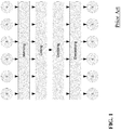
- FIG. 1 where the letter c refers to audio channel.
- the input channels e.g. 5.1 channels
- the encoder that performs matrixing to exploit inter-channel relations, following by coding of the matrixed signal into a bit-stream.
- the matrixing information may also be conveyed to the decoder as part of the bitstream. At the decoder side this process is reversed.
- MPEG Surround provides a multi-channel audio coding tool that allows existing mono- or stereo-based coders to be extended to multi-channel audio applications.
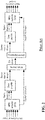
- FIG. 2 illustrates an example of elements of an MPEG Surround system.
- an MPEG Surround decoder can recreate the spatial image by a controlled upmix of the mono- or stereo signal to obtain a multichannel output signal.
- MPEG Surround allows for decoding of the same multi-channel bit-stream by rendering devices that do not use a multichannel speaker setup.
- An example is virtual surround reproduction on headphones, which is referred to as the MPEG Surround binaural decoding process. In this mode a realistic surround experience can be provided while using regular headphones.
- Another example is the transformation of higher order multichannel outputs, e.g. 7.1 channels, to lower order setups, e.g. 5.1 channels.
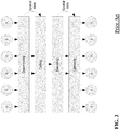
- FIG. 3 The approach of MPEG Surround (and similar parametric multi-channel coding approaches such as Binaural Cue Coding or Parametric Stereo) is illustrated in FIG. 3 .
- the input channels are downmixed (e.g. to a stereo mix).
- This downmix is subsequently coded using traditional coding techniques such as the AAC family of codecs.
- a representation of the spatial image is also transmitted in the bit-stream.
- the decoder reverses the process.
- MPEG standardized a format known as 'Spatial Audio Object Coding' (MPEG-D SAOC).
- MPEG-D SAOC provides efficient coding of individual audio objects rather than audio channels.
- each speaker channel can be considered to originate from a different mix of sound objects
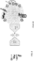
- SAOC makes individual sound objects available at the decoder side for interactive manipulation as illustrated in FIG. 4 .
- multiple sound objects are coded into a mono or stereo downmix together with parametric data allowing the sound objects to be extracted at the rendering side thereby allowing the individual audio objects to be available for manipulation e.g. by the end-user.
- FIG. 5 illustrates an interactive interface that enables the user to control the individual objects contained in an SAOC bitstream. By means of a rendering matrix individual sound objects are mapped onto speaker channels.
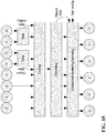
- FIG. 6 provides a high level block diagram of a parametric approach of SAOC (or similar object coding systems).
- the object signals (o) are downmixed and the resulting downmix is coded.
- parametric object data is transmitted in the bit-stream relating the individual objects to the downmix.
- the objects are decoded and rendered to channels according to the speaker configuration. Typically, in such an approach it is more efficient to combine the decoding of the objects and the speaker rendering.
- SAOC transmits audio objects instead of reproduction channels.
- This allows the decoder-side to place the audio objects at arbitrary positions in space, provided that the space is adequately covered by speakers. This way there is no relation between the transmitted audio and the reproduction setup, hence arbitrary speaker setups can be used. This is advantageous for e.g. home cinema setups in a typical living room, where the speakers are almost never at the intended positions because of the layout of living room.
- SAOC it is decided at the decoder side where the objects are placed in the sound scene. This is often not desired from an artistic point-of-view, and therefore the SAOC standard does provide ways to transmit a default rendering matrix in the bitstream, eliminating the decoder responsibility. These rendering matrices are again tied to specific speaker configurations.
- the object extraction only works within certain boundaries. It is typically not possible to extract a single object with high enough separation from the other objects for reproduction without the other objects, e.g. in a Karaoke use case.
- the SAOC technology does not scale well with bitrate.
- the approach of downmixing and extracting (upmixing) audio objects results in some inherent information loss that is not fully compensated even at very high bitrates. Thus, even if the bitrate is increased, the resulting audio quality is typically degraded and prevents the encoding/decoding operations from being fully transparent.
- SAOC supports so called residual coding which can be applied for a limited set of objects (up to and including 4, which has been a design choice).
- the residual coding basically transmits additional bitstream components that code the error signals (including the crosstalk from the other objects in that object) such that a limited number of objects can be extracted with a high degree of object separation.
- Residual waveform components may be supplied up to a specific frequency such that the quality can be gradually increased.
- the resulting object is thus a combination of a parametric component and a waveform component.
- 3DAA 3D Audio Alliance
- SRS Sound Retrieval System
- 3DAA is dedicated to develop standards for the transmission of 3D audio, that "will facilitate the transition from the current speaker feed paradigm to a flexible object-based approach".
- 3DAA a bitstream format is to be defined that allows the transmission of a legacy multichannel downmix along with individual sound objects.
- object positioning data is included. The principle of generating a 3DAA audio stream is illustrated in FIG. 7 .
- the sound objects are received separately in the extension stream and these may be extracted from the multi-channel downmix.
- the resulting multi-channel downmix is rendered together with the individually available objects.
- a multichannel reference mix can be transmitted with a selection of audio objects.
- 3DAA transmits the 3D positional data for each object.
- the objects can then be extracted using the 3D positional data.
- the inverse mix-matrix may be transmitted, describing the relation between the objects and the reference mix.
- the illustration of FIG. 6 may be considered to also correspond to the approach of 3DAA.
- Both the SAOC and 3DAA approaches incorporate the transmission of individual audio objects that can be individually manipulated at the decoder side.
- SAOC provides information on the audio objects by providing parameters characterizing the objects relative to the downmix (i.e. such that the audio objects are generated from the downmix at the decoder side)
- 3DAA provides audio objects as full and separate audio objects (i.e. that can be generated independently from the downmix at the decoder side).
- FIG. 8 illustrates the current high level block diagram of the intended MPEG 3D Audio system.
- the approach is intended to also support object based and scene based formats.
- An important aspect of the system is that its quality should scale to transparency for increasing bitrate, i.e. that as the data rate increases the degradation caused by the encoding and decoding should continue to reduce until it is insignificant.
- HE-AAC v2, MPEG Surround, SAOC, USAC the compensation of information loss for the individual signals tends to not be fully compensated by the parametric data even at very high bit rates. Indeed, the quality will be limited by the intrinsic quality of the parametric model.
- MPEG-3D Audio furthermore seeks to provide a resulting bitstream which is independent of the reproduction setup.
- Envisioned reproduction possibilities include flexible loudspeaker setups up to 22.2 channels, as well as virtual surround over headphones and closely spaced speakers.
- DirAC DirAC - Directional Audio Coding
- PMEG Motion Picture Experts Group
- SAOC DirAC - Directional Audio Coding
- these parameters represent results from direction and diffuseness analysis (azimuth, elevation and diffuseness ⁇ (t/f)).
- the downmix is divided dynamically into two streams, one that corresponds to non-diffuse sound (weight 1 ⁇ ⁇ ), and another that corresponds to the diffuse sound (weight ⁇ ).
- the non-diffuse sound stream is reproduced with a technique aiming at point-like sound sources, and the diffuse sound stream with a technique aiming at the perception of sound lacking prominent direction.
- the approach of DirAC is illustrated in FIG. 9 .
- DirAC can be considered a recording based encoding/decoding system in accordance with the approach of FIG. 10 .
- the microphone signals (m) are coded. This can e.g. be performed similarly to the parametric approach using downmixing and coding of spatial information.
- the microphone signals can be reconstructed, and based on a provided speaker configuration, the microphone signals can be rendered to channels. It is noted that for efficiency reasons, the decoding and rendering process can be integrated into a single step.
- Audio content is nowadays shared between an increasing number of different reproduction devices.
- the audio may be experienced over headphones, small speakers, via a docking station, and/or using various multichannel setups.
- the ITU recommended 5.1 speaker setup which conventionally has been assumed as the nominal speaker setup, is often not even approximately applied when rendering the audio content.
- Speakers are placed at convenient locations instead of at the recommended angles and distances.
- alternative setups like 4.1, 6.1, 7.1 or even 22.2 configurations may be used.
- Such approaches are increasingly introduced (currently mainly for cinema applications but domestic use is expected to become more common) to replace the conventional audio channel approach where each audio channel is associated with a nominal position.
- an audio scene can best be represented by the individual audio objects in the scene.
- the objects can then each be rendered separately on the reproduction channels such that the spatial perception is closest to the intended perception.
- Coding the objects as separate audio signals/streams requires a relatively high bitrate.
- the available solutions viz. SAOC, DirAC, 3DAA, etc
- SAOC, DirAC, 3DAA, etc transmit downmixed object signals and means to reconstruct the object signals from this downmix. This results in a significant bitrate reduction.
- SAOC provides speaker independent audio by efficient object coding in a downmix with object extraction parameters
- 3DAA defines a format where the scene is described in terms of object positions. DirAC attempts an efficient coding of audio objects by using a B-format downmix.
- these systems are suitable for efficient and flexible coding and rendering of audio content.
- Significant data rate reductions can be achieved and accordingly relatively low data rate implementations can still provide reasonable or good audio quality.
- an issue with such systems is that the audio quality is inherently limited by the parametric encoding and downmixing. Even as the available data rate is increased, it is not possible to achieve full transparency where the impact of the encoding/decoding operations cannot be detected. In particular, objects cannot be reconstructed without cross-talk from other objects even at high data rates. This results in a reduction of audio quality and spatial perception when objects are separated in spatial reproduction (i.e. rendered at different positions).
- a further drawback is that inter-object coherence is mostly not reconstructed properly, which is an important characteristic for creating spatial perception. Attempts to reconstruct the coherence are based on use of decorrelators and tend to result in suboptimal audio quality.
- An alternative approach of individually waveform encoding the audio objects may allow high quality at high data rates, and may in particular provide full scalability including a full transparent encoding/decoding. However, such approaches are unsuitable for low data rates where they do not provide an efficient encoding.
- parametric downmix based encodings are suitable for low data rates and scalability towards lower data rates whereas waveform object encodings are suitable for high data rates and scalability towards high data rates.
- Scalability is a very important criterion for future audio systems, and therefore it is highly desirable to have efficient scalability that extends to both very low data rates and to very high data rates, and in particular to full transparency. Furthermore, it is desirable that such scalability has a low granularity of the scalability.
- the Invention seeks to preferably mitigate, alleviate or eliminate one or more of the above mentioned disadvantages singly or in any combination.
- a decoder comprising: a receiver for receiving an encoded data signal representing a plurality of audio objects not being associated with a rendering configuration, the encoded data signal comprising encoded time-frequency tiles for the plurality of audio objects, the encoded time-frequency tiles comprising non-downmix time-frequency tiles and downmix time-frequency tiles, each downmix time-frequency tile being a downmix of at least two time-frequency tiles of the plurality of audio objects and each non-downmix time-frequency tile representing only one time-frequency tile of the plurality of audio objects, the encoded data signal further comprising a downmix indication for time-frequency tiles of the plurality of audio objects, the downmix indication indicating whether time-frequency tiles of the plurality of audio objects are encoded as downmix time-frequency tiles or non-downmix time-frequency tiles; a generator for generating a set of output signals from the encoded time-frequency tiles, the generation of the output signals comprising an upmixing for encoded time-frequency tiles that are indicated by the downmix indication
- the invention may allow improved audio decoding, and in particular may in many embodiments allow an improved scalability.
- the invention may in many embodiments allow data rate scalability to transparency.
- encoding artifacts known for parametric encoding at higher data rates may be avoided or mitigated in many scenarios.
- the approach may further provide efficient encoding, and in particular may provide efficient encoding at lower data rates.
- a high degree of scalability can be achieved, and in particular scalability to efficient encoding at lower data rates and very high quality (and specifically transparency) at high data rates can be achieved.
- the invention may provide a very flexible system with a high degree of adaptation and optimization being possible.
- the encoding and decoding operation may be adapted not only to the overall characteristics of the audio objects but also to characteristics of individual time-frequency tiles. Accordingly a highly efficient coding can be achieved.
- the upmixing of a downmix time-frequency tile may be a separate operation or may be integrated with other operations.
- the upmixing may be part of a matrix (vector) operation that multiplies signal values for the time-frequency tile with matrix (vector) coefficients where the matrix (vector) coefficients reflect an upmix operation but may further reflect other operations, such as a mapping to output rendering channels.
- the upmixing need not be an upmixing of all components of a downmix.
- the upmix may be a partial upmix to generate only one of the time-frequency tiles comprised in the downmix.
- a time-frequency tile is a time-frequency interval.
- a time-frequency tile of the output signals may be generated from encoded time-frequency tiles covering the same time interval and frequency interval.
- each downmix time-frequency tile may be a downmix of time-frequency tiles of the audio signals covering the same time interval and frequency interval.
- the time-frequency intervals may be on a uniform grid or may e.g. be on a non-uniform grid, in particular for the frequency dimension. Such a uniform grid may for example be used to exploit and reflect the logarithmic sensitivity of the human hearing.
- the generation of the output signals need (do) not include upmixing.
- Time-frequency tiles of the plurality of audio objects may not be represented in the encoded time-frequency tiles.
- Time-frequency tiles of the plurality of audio objects may not be represented in either an encoded downmix time-frequency tile or a non-downmix time-frequency tile.
- the indicating of whether time-frequency tiles of the plurality of audio objects are encoded as downmix time-frequency tiles or non-downmix time-frequency tiles may be provided with reference to the encoded time-frequency tiles.
- a downmix indication value may be provided individually for time-frequency tiles of the plurality of audio objects. Equivalently, in some embodiments a downmix indication value may be provided for a group of time-frequency tiles of the plurality of audio objects.
- a non-downmix time-frequency tile represents data for only one time-frequency tile of the audio objects whereas a downmix time-frequency tile represents two or more time-frequency tiles of the audio objects.
- the downmix time-frequency tiles and non-downmix time-frequency tiles may in different embodiments be encoded in different ways in the encoded data signal, including for example each tile being separately encoded, some or all being jointly encoded etc.
- the encoded data signal furthermore comprises parametric upmix data, and wherein the generator is arranged to adapt the upmixing operation in response to the parametric data.
- the invention may allow a flexible adaptation and interworking of e.g. waveform and parametric encoding to provide a very scalable system, and in particular a system capable of providing very high audio quality for high data rates while providing efficient encoding at lower data rates.
- the generator may specifically generate the output signals in response to the parametric upmix data for encoded time-frequency tiles that are indicated by the downmix indication to be downmix time-frequency tiles (and not for encoded time-frequency tiles that are indicated by the downmix indication to not be encoded downmix time-frequency tiles).
- the generator comprises a rendering unit arranged to map time-frequency tiles for the plurality of audio objects to output signals corresponding to a spatial sound source configuration.
- the upmixing and render mapping may in some embodiments be performed as a single integrated operation, e.g. as a single matrix multiplication.
- the generator is arranged to generate the decoded audio objects from the encoded time-frequency tiles, and to generate the audio signals by spatially mapping the decoded audio objects to the set of output signals, the set of output signals corresponding to a spatial sound source setup.
- the generator is arranged to generate time-frequency tiles for the set of output signals by applying matrix operations to the encoded time-frequency tiles, coefficients of matrix operations including upmix components for encoded time-frequency tiles for which the downmix indication indicates that the encoded time-frequency tile is a downmix time-frequency tile and not for encoded time-frequency tiles for which the downmix indication indicates that the encoded time-frequency tile is a non-downmix time-frequency tile.
- the matrix operations may be applied to the signal samples of the encoded time-frequency tiles.
- the signal samples may be generated by a decoding operation.
- At least one audio signal is represented in the decoded signal by at least one non-downmix time-frequency tile and at least one downmix time-frequency tile.
- the individual audio objects may be represented by both downmix time-frequency tiles and non-downmix time-frequency tiles.
- Each time-frequency tile of the audio signal may be represented by a downmix time-frequency tile or a non-downmix time-frequency tile without requiring that all time-frequency tiles are represented in the same way.
- the approach may allow for a high degree of flexibility and optimization, and may specifically result in improved audio quality, coding efficiency and/or scalability.
- the downmix indication for at least one downmix time-frequency tile comprises a link between an encoded downmix time-frequency tile and a time-frequency tile of the plurality of audio objects.
- This may in many embodiments allow encoding to be flexibly optimized on a time-frequency tile basis.
- the approach may allow a high degree of flexibility and optimization, and may specifically result in improved audio quality, coding efficiency and/or scalability.
- At least one audio signal of the plurality of audio objects is represented by two downmix time-frequency tiles being downmixes of different set of audio objects of the plurality of audio objects.
- This may in many embodiments allow encoding to be flexibly optimized on a time-frequency tile basis.
- the approach may allow a high degree of flexibility and optimization, and may specifically result in improved audio quality, coding efficiency and/or scalability.
- At least one audio signal of the plurality of audio objects is represented by encoded time-frequency tiles that include at least one encoded time-frequency tile not being an non-downmix time-frequency tile or a downmix time-frequency tile.
- the encoded time-frequency tiles not being non-downmix time-frequency tiles or a downmix time-frequency tiles may for example be encoded as null-time-frequency tiles (encoded as an empty time-frequency tile with no signal data), or may e.g. be encoded using other techniques such as mid/side encoding.
- At least one downmix time-frequency tile is a downmix of an audio object not being associated with a nominal sound source position of a sound source rendering configuration and an audio channel being associated with a nominal sound source position of a sound source rendering configuration.
- the downmix time-frequency tiles may include downmixes of time-frequency tiles of audio objects and audio channels.
- At least some of the non-downmix time-frequency tiles are waveform encoded.
- This may allow efficient and potentially high quality encoding/decoding. In many scenarios it may allow improved scalability, and in particular scalability to transparency.
- At least some of the downmix time-frequency tiles are waveform encoded.
- the generator (1403) is arranged to upmix the downmix frequency tiles to generate upmixed time-frequency tiles for at least one of the plurality of audio objects of a downmix time-frequency tile; and the generator is arranged to generate time-frequency tiles for the set of output objects using the upmixed time-frequency tiles for tiles for which the downmix indication indicates that the encoded time-frequency tile is a downmix time-frequency tile.
- method of decoding comprising: receiving an encoded data signal representing a plurality of audio objects not being associated with a rendering configuration, the encoded data signal comprising encoded time-frequency tiles for the plurality of audio objects, the encoded time-frequency tiles comprising non-downmix time-frequency tiles and downmix time-frequency tiles, each downmix time-frequency tile being a downmix of at least two time-frequency tiles of the plurality of audio objects and each non-downmix time-frequency tile representing only one time-frequency tile of the plurality of audio objects, the encoded data signal further comprising a downmix indication for time-frequency tiles of the plurality of audio objects, the downmix indication indicating whether time-frequency tiles of the plurality of audio objects are encoded as downmix time-frequency tiles or non-downmix time-frequency tiles; and generating a set of output signals from the encoded time-frequency tiles, the generation of the output signals comprising an upmixing for encoded time-frequency tiles that are indicated by the downmix indication to be downmix time-frequency tiles
- an encoder comprising: a receiver for receiving a plurality of audio objects not being associated with a rendering configuration, each audio signal comprising a plurality of time-frequency tiles; a selector for selecting a first subset of the plurality of time-frequency tiles to be downmixed; a downmixer for downmixing time-frequency tiles of the first subset to generate downmixed time-frequency tiles; a first encoder for generating downmix encoded time-frequency tiles by encoding the downmix time-frequency tiles; a second encoder for generating non-downmix time-frequency tiles by encoding a second subset of the time-frequency tiles of the audio objects without downmixing of time-frequency tiles of the second subset; a unit for generating a downmix indication indicating whether time-frequency tiles of the first subset and the second subset are encoded as downmix encoded time-frequency tiles or as non-downmix time-frequency tiles; an output for generating an encoded audio signal representing the plurality of
- the invention may allow improved audio encoding, and in particular may in many embodiments allow an improved scalability.
- the invention may in many embodiments allow data rate scalability to transparency.
- encoding artifacts known for parametric encoding at higher data rates may be avoided or mitigated in many scenarios.
- the approach may further provide efficient encoding, and in particular may provide efficient encoding at lower data rates.
- a high degree of scalability can be achieved, and in particular scalability to efficient encoding at lower data rates and very high quality (and specifically transparency) at high data rates can be achieved.
- the invention may provide a very flexible system with a high degree of adaptation and optimization being possible.
- the encoding and decoding operation may be adapted not only to the overall characteristics of the audio objects but also to characteristics of individual time-frequency tiles. Accordingly a highly efficient coding can be achieved.
- the downmixer may further be arranged to generate parametric data for restoring time-frequency tiles being downmixed from the downmixed time-frequency tiles; and the output may be arranged to include the parametric data in the encoded audio signal.
- the first and second encoders may be implemented as a single encoder, e.g. encoding the downmixes sequentially and possibly using the same encoding algorithm.
- the encoding process may take a set of downmix time-frequency tiles and individual time-frequency tiles into account to improve efficiency and quality.
- the selector is arranged to select time-frequency tiles for the first subset in response to a target data rate for the encoded audio signal.
- This may provide improved performance, and may in particular allow an efficient scaling of the encoded audio signal.
- the selector is arranged to select time-frequency tiles for the first subset in response to at least one of: an energy of the time-frequency tiles; a spatial characteristic of the time-frequency tiles; and a coherence characteristic between pairs of the time-frequency tiles.
- a method of encoding comprising: receiving a plurality of audio objects not being associated with a rendering configuration, each audio signal comprising a plurality of time-frequency tiles; selecting a first subset of the plurality of time-frequency tiles to be downmixed; downmixing time-frequency tiles of the first subset to generate downmixed time-frequency tiles; generating downmix encoded time-frequency tiles by encoding the downmixed time-frequency tiles; generating non-downmix time-frequency tiles by encoding a second subset of the time-frequency tiles of the audio objects without downmixing of time-frequency tiles of the second subset; generating a downmix indication indicating whether time-frequency tiles of the first subset and the second subset are encoded as downmixed encoded time-frequency tiles or as non-downmix time-frequency tiles; and generating an encoded audio signal representing the plurality of audio objects, the encoded audio signal comprising the non-downmix time-frequency tiles, the downmix encoded
- An encoding and decoding system comprising the encoder and the decoder described above may be provided.
- an encoded data signal representing a plurality of audio objects not being associated with a rendering configuration
- the encoded data signal comprising encoded time-frequency tiles for the plurality of audio objects, the encoded time-frequency tiles comprising non-downmix time-frequency tiles and downmix time-frequency tiles, each downmix time-frequency tile being a downmix of at least two time-frequency tiles of the plurality of audio objects and each non-downmix time-frequency tile representing only one time-frequency tile of the plurality of audio objects
- the encoded data signal further comprising a downmix indication for time-frequency tiles of the plurality of audio objects, the downmix indication indicating whether time-frequency tiles of the plurality of audio objects are encoded as downmix time-frequency tiles or non-downmix time-frequency tiles.
- FIG. 12 illustrates an example of an audio rendering system in accordance with some embodiments of the invention.
- the system comprises an encoder 1201 which receives audio signals to be encoded.
- the encoded audio data is transmitted to a decoder 1203 via a suitable communication medium 1205
- the audio signals provided to the encoder 1201 may be provided in different forms and generated in different ways.
- the audio signals may be audio captured from microphones and/or may be synthetically generated audio such as for example for computer games applications.
- the audio signals may include a number of components that may be encoded as individual audio objects, such as e.g. specific synthetically generated audio objects or microphones arranged to capture a specific audio source, such as e.g. a single instrument.
- Each audio object typically corresponds to a single sound source.
- the audio objects typically do not comprise components from a plurality of sound sources that may have substantially different positions.
- each audio object typically provides a full representation of the sound source.
- Each audio object is thus typically associated with spatial position data for only a single sound source.
- each audio object may typically be considered a single and complete representation of a sound source and may be associated with a single spatial position.
- Audio objects are not associated with any specific rendering configuration and are specifically not associated with any specific spatial configuration of sound transducers/ speakers. Thus, in contrast to sound channels which are associated with a rendering configuration such as a specific spatial speaker setup (e.g. a surround sound setup), audio objects are not defined with respect to any specific spatial rendering configuration.
- a rendering configuration such as a specific spatial speaker setup (e.g. a surround sound setup)
- audio objects are not defined with respect to any specific spatial rendering configuration.
- An audio object is thus typically a single or combined sound source treated as an individual instance, e.g. a singer, instrument or a choir.
- the audio object has associated spatial position information that defines a specific position for the audio object, and specifically a point source position for the audio object. However, this position is independent of a specific rendering setup.
- An object (audio) signal is the signal representing an audio object.
- An object signal may contain multiple objects, e.g. not concurrent in time.
- an audio channel is associated with a nominal audio source position.
- An audio channel thus typically has no associated position data but is associated with a nominal position of a speaker in a nominal associated speaker configuration.
- an audio channel is typically associated with a speaker position in an associated configuration, an audio object is not associated with any speaker configuration.
- the audio channel thus represents the combined audio that should be rendered from the given nominal position when rendering is performed using the nominal speaker configuration.
- the audio channel thus represents all audio sources of the audio scene that require a sound component to be rendered from the nominal position associated with the channel in order for the nominal speaker configuration to spatially render the audio source.
- An audio object in contrast is typically not associated with any specific rendering configuration and instead provides the audio that should be rendered from one sound source position in order for the associated sound component to be perceived to originate from that position.
- the spatial audio encoding device 1201 is arranged to generate an encoded signal which contains encoded data that represents the audio signals (specifically audio objects and/or audio channels) provided to the spatial audio encoding device 1201.
- the encoded audio stream may be communicated through any suitable communication medium including direct communication or broadcast links.
- communication may be via the Internet, data networks, radio broadcasts etc.
- the communication medium may alternatively or additionally be via a physical storage medium such as a CD, Blu-RayTM disc, memory card etc.
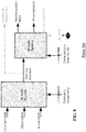
- FIG. 13 illustrates elements of the encoder 1201 in more detail.
- the encoder 1201 receives a plurality of audio signals which in the specific example are audio objects (in the specific example four audio objects O 1 to O 4 are shown but it will be appreciated that these merely represent any plurality of audio objects).
- the audio objects are received by an encode receiver 1301 which provides time-frequency tiles for the audio objects to the remaining parts of the encoder 1201.
- a time-frequency tile for a signal corresponds to the signal in a given time interval and a given frequency interval.
- representing a signal in time-frequency tiles means that the signal is represented in a number of tiles where each tile has an associated frequency interval and an associated time interval.
- Each time-frequency tile may provide a single (typically complex) value reflecting the signal value in the associated time interval and frequency interval.
- time-frequency tiles may also provide a plurality of signal values.
- a signal is often divided into uniform time-frequency tiles, i.e. the time and/or frequency interval is often of the same size for all time-frequency tiles.
- non-uniform time-frequency tiles may be used, e.g. by using time-frequency tiles for which the size of the frequency interval increases for increasing frequencies.
- the audio signals may already be provided to the encoder as time-frequency tile representations.
- the encode receiver 1301 may generate such representations. This may typically be done by segmenting the signals into time segments (e.g. of a 20 msec duration) and performing a time to frequency transform such as an FFT on each segment.
- the resulting frequency domain values may each directly represent a time-frequency tile, or in some cases a plurality of adjacent frequency bins (adjacent in time and / or frequency) may be combined into a time-frequency tile.
- the encode receiver 1301 is coupled to a selector 1303 which receives the tiles of the audio objects.
- the selector 1303 is then arranged to select some tiles that will be encoded as downmixed tiles and some tiles that will be encoded as non-downmixed tiles.
- the downmixed tiles will be tiles that are generated by downmixing at least two tiles typically from at least two audio objects whereas non-downmix tiles will be encoded without any downmixing.
- the non-downmix tiles will comprise data from only one tile of the audio objects/signals being encoded.
- a non-downmix tile will include a contribution from only one audio object whereas downmix tiles will include components/ contribution from at least two tiles and typically at least two audio objects.
- a non-downmix tile is specifically a tile that is not a downmix of two or more tiles.
- the selector 1303 is coupled to downmixer 1305 which is fed the tiles selected by the selector 1303. It then proceeds to generate a downmix tile from these tiles. For example, two corresponding (same frequency interval and time interval) tiles from different audio objects that are intended to be downmixed are by the downmixer 1305 downmixed to generate a single downmixed tile. This approach is performed for the plurality of tiles thereby generating a set of downmixed tiles, where each downmix tile represents at least two tiles and typically from at least two audio objects.
- the downmixer 1305 further generates parametric (upmix) data which can be used to recreate the original audio object tiles by performing an upmixing of the downmix tiles.
- the downmixer 1305 may generate Inter-object Level Difference (ILD), Inter-object Time Difference (ITD), Inter-object Phase Differences (IPD), and/or Inter-object Coherence Coefficients (ICC) as will be well known to the person skilled in the art.
- ILD Inter-object Level Difference
- ITD Inter-object Time Difference
- IPD Inter-object Phase Differences
- ICC Inter-object Coherence Coefficients
- the downmix tiles are fed to a first encoder 1307 which proceeds to encode each downmix tile to generate an encoded downmix tile.
- the encoder may for example be a simple quantization of the values of the downmix tiles, and may specifically be an encoding which maintains the waveform represented by the downmix tile.
- the upmix parameters may also be provided to the first encoder 1307 which may encode these using any suitable encoding approach.
- the selector 1303 is furthermore coupled to a second encoder 1309 which is fed the tiles that are to be non-downmix tiles. The second encoder then proceeds to encode these tiles.
- FIG. 13 illustrates the first and second encoder 1307, 1309 as separate functional units, they may be implemented as a single encoder and the same encoding algorithm may be applied to both downmix tiles and non-downmix tiles.
- any encoding of the downmix and non-downmix tiles may be used to generate a suitable encoded data signal.
- all tiles may be separately encoded.
- individual encoding may be performed for each tile without consideration or impact from any other tiles, i.e. the encoded data for each tile may be generated independently of other tiles.
- a quantization and channel coding may be performed separately for each tile (whether downmix or non-downmix) to generate data that is combined to generate the encoded data.
- some joint encoding of tiles may be used. Specifically, a selection of downmix tiles and/or non-downmix tiles may be encoded jointly to improve efficiency by exploiting specific properties and/or correlation of the tiles and/or the objects represented by the tiles.
- the selector 1303 is furthermore coupled to an indication processor 1311 which receives information of which tiles are encoded as downmix tiles and which are non-downmix.
- the indication processor 1311 then proceeds to generate a downmix indication that indicates whether the tiles of audio objects are encoded as downmixed tiles or as non-downmix tiles.
- the downmix indication may for example comprise data for each tile of each of the audio objects where the data for a given tile indicates whether this has been non-downmix or encoded as a downmix. In the latter case, the data may further indicate which other audio objects are downmixed into the same downmix. Such data may allow the decoder to identify which data of the encoded data signal should be used to decode a specific tile.
- the first encoder 1307, the second encoder 1309, and the indication processor 1311 are coupled to an output processor 1313 which generates an encoded audio signal that includes the non-downmix tiles, the downmix encoded tiles, and the downmix indication.
- the upmix parameters are also included.
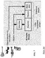
- FIG. 14 illustrates elements of the decoder 1203 in more detail.
- the decoder 1203 comprises a receiver 1401 which receives the encoded signal from the encoder 1201.
- the receiver receives an encoded data signal that represents the plurality of audio objects, with the encoded data signal comprising encoded tiles that are either coded as downmix tiles or as non-downmix tiles.
- the encoded data signal comprises encoded tiles that are either coded as downmix tiles or as non-downmix tiles.
- the downmix indication that indicates how the separation of the original audio tiles into the different types of encoded tiles has been performed.
- the upmix parameters are also included.
- the receiver 1401 is coupled to a generator 1403 which is fed the received tiles and the downmix indicator, and which in response proceeds to generate a set of output signals.
- the output signals may for example be the decoded audio objects which may then be processed or otherwise manipulated in a post processing operation.
- the generator 1403 may directly generate output signals that are suitable for rendering using a given rendering setup (and specifically speaker configuration).
- the generator 1403 may in some scenarios comprise functionality for mapping the audio objects onto audio channels of a specific rendering configuration.
- the generator 1403 is arranged to process encoded tiles differently according to whether they are downmix tiles or non-downmix tiles. Specifically, for tiles that are indicated by the downmix indication to be downmix tiles, the generation of tiles for the output signals comprises an upmixing operation.
- upmixing operation may specifically correspond to an extraction or reproduction of a tile for an audio object from a downmix tile in which the audio object tile has been downmixed.
- this data is used in the upmixing operation of the downmixed tiles.
- the generator 1403 may comprise a reproduction generator 1405 which reproduces the original audio objects.
- the reproduction generator 1405 may for example process each audio object one at a time, and with each audio object being processed one tile at a time.
- the reproduction generator 1405 may for a given (time) segment start with tile 1 (e.g. the lowest frequency tile) of audio object 1.
- the downmix indication is then evaluated for tile 1 for object 1. If the downmix indication indicates that the encoded tile for tile 1 of object 1 is non-downmix, the encoded tile is decoded to directly provide tile 1 of object 1. However, if the downmix indication indicates that the encoded tile for tile 1 of object 1 is downmix encoded, the encoded tile is first decoded to provide the downmix tile and consecutively upmixed to reproduce the original tile 1 of audio object 1. This upmixing of the (encoded) downmix tile thus creates an (estimate) of tile 1 of audio object 1 prior to it being downmixed at the encoder.
- the upmixing may specifically use the parametric upmix data if such data is available. However, if no such data is provided, the upmixing may be a blind upmixing.
- the result of the upmix operation applied to encoded tile 1 of object 1 is thus (an estimate of) tile 1 of audio object 1 as fed to the encoder 1201.
- the result of the operation is tile 1 of object 1 where the generation of the tile depends on whether the downmix indication indicates that this has been encoded as a downmix or as a non-downmix tile.
- the reproduction generator 1405 then proceeds to perform the exact same operation for tile 2 of audio object 1, thereby resulting in a decoded tile 2 of audio object 1.
- the process is repeated for all tiles of audio object 1 and the resulting collection of generated tiles thus provides a time-frequency tile representation of audio object 1.
- This may be output by the reproduction generator 1405 (or the generator 1403), or if e.g. a time domain signal is required, a frequency to time domain transformation may be applied (e.g. an iFFT).
- each encoded downmix tile is a downmix of, say, tiles of audio object 1 and 3, an upmix operation will be performed both when audio object 1 is generated and when audio object 3 is generated.
- the upmix operations will use different upmix parameters (specifically the parameters that are provided for the specific object).
- the upmixing may simultaneously provide both (or all) of the upmixed tiles.
- a matrix operation may be used to directly generate the upmixed tiles for both audio object 1 and 3.
- the total upmix operation may for example be performed when the algorithm first encounters a given encoded downmix tile (e.g. when processing object 1).
- the resulting upmixed tiles for other objects may be stored such that no separate upmix operation is required when the other tiles downmixed into the encoded downmix tile are encountered (e.g. when processing object 3 in the specific example).
- only one upmixed tile may be generated from one encoded downmix tile by the upmixing operations of the reproduction generator 1405. For example, if only object 1 is generated by the reproduction generator 1405, the upmixing of a given downmix tile only needs to provide the upmixed tile for object 1.
- the decoded audio objects may be directly output from the generator 1403.
- the decoded audio objects are fed to a rendering processor 1407 which are arranged to generate output signals corresponding to a specific rendering setup, and specifically to a specific speaker configuration.
- the rendering processor 1407 may thus map the audio objects to output channels where each output channel is associated with a nominal sound rendering position. For example, a number of audio objects may be mapped to the audio channels of a 5.1 surround sound speaker setup.
- the generator 1403 is shown to have separate functionality for generating the audio objects and for rendering these.
- the functionality of the reproduction generator 1405 and the rendering processor 1407 may be combined into a single integrated function or operation.
- the generator may directly generate the rendering output from the encoded data without generating the audio objects as explicit intermediate signals.
- the upmixing operation may be performed as a matrix operation/ multiplication (or even as a complex multiplication if only one upmix value is to be generated).
- the rendering mapping may be performed as a matrix operation/ multiplication).
- One or more matrix operations/multiplications may specifically be a vector operation/multiplication (i.e. using a matrix with only one column or row). It will be appreciated that the two sequential multiplications may be combined into a single matrix multiplication applied to the tile values of the encoded tiles. This can be achieved by the matrix multiplication having matrix coefficients that reflect both the upmixing (if performed) and the rendering mapping.
- Such a matrix may e.g. be generated simply by multiplying the individual matrices associated with the upmixing and rendering mapping.
- the upmixing is performed as an integral part of a single matrix operation and without requiring an explicit generation of the upmix tile values or the audio objects as intermediate signals.
- the matrix coefficients may thus reflect/include an upmixing for tiles that are indicated to be downmix tiles but not for tiles that are indicated to be non-downmix tiles.
- the matrix coefficients may depend on upmix parameters received in the encoded data signal when the downmix indication indicates that the tile is downmix tile but not when it indicates that the tile is a non-downmix tile.
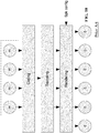
- FIG. 15 The approach of the system of FIG. 12 may be illustrated by FIG. 15 .
- a subset of audio objects is provided directly for coding and is encoded as non-downmix tiles, i.e. without any downmixing.
- audio objects of another subset are not provided directly for encoding but are first combined with other audio objects in a downmix.
- four audio objects are pairwise downmixed to two downmixes.
- the downmix furthermore generates parametric upmix data (object data) which describes/defines how the original audio objects may be generated from the downmix.
- the downmix and parametric data accordingly provides a data reduction in comparison to the original signals.
- the downmixes are then coded together with the parametric data.
- the coding may first be undone to generate the signal values for the non-downmix signals and for the upmixes.
- the resulting signals are then processed to generate suitable output channels. This processing includes upmixing for the downmixes (based on the parametric upmix data) and a mapping of the audio objects to the specific speaker configuration.
- the signals are processed in a time-frequency tile representation, and specifically by processing in the time-frequency tile domain.
- a downmix indication is provided which may for individual tiles indicate whether the individual audio object tiles are encoded as downmix tiles or as non-downmix tiles.
- This downmix indication is communicated from encoder to decoder and accordingly allows the allocation of tiles as downmix or non-downmix tiles to be performed on a tile per tile basis.
- FIG. 15 may be considered to represent the approach for a specific tile, i.e. for a specific time and frequency interval.
- the same audio objects may be encoded using a different allocation of tiles into downmix encoded and non-downmix tiles.
- the system may provide a very flexible encoding, and the highly granular approach may allow substantial optimisation for a given target rate with the optimisation being specific for the specific signal characteristics.
- the approach allows for a very efficient trade-off between the relative merits of downmix encoding and non-downmix encoding (and thus between the relative merits of parametric encoding and waveform encoding). For example, for lower data rates, a relatively large number of tiles may be parametrically encoded as downmix tiles with associated parameters. However, it is still possible to encode critical tiles without any downmixing thereby reducing the possible quality degradation of parametric encoding. As the target/ available data rate is increased, an increasing number of tiles may be non-downmix tiles thereby increasing the quality (specifically the audio objects are increasingly waveform encoded rather than parametrically encoded and in particular audio object cross talk may be reduced). This trend may be continued until all tiles are non-downmix tiles and the entire encoding and decoding approach becomes transparent. Thus, a highly efficient encoding and scalability to transparency can be achieved.
- the system of FIG. 12 may thus be seen as a hybrid waveform/parametric approach which uses pre-combining of a subset of the available tiles into downmixed tiles along with accompanying parametric information.
- the remaining tiles together with the downmixed tiles may be coded using traditional waveform coding tiles.
- the parametric information will relate the downmixed tiles to the audio object tiles.
- information about how each object is represented (purely waveform or waveform plus parametric information - i.e. whether non-downmix or downmix encoded) is also conveyed in the encoded data signal.
- One particular example is the coding of a diffuse sound field. Under the assumption that the diffuse sound field is indeed omnidirectional, this requires a virtually unlimited number of objects to represent the diffuse sound field. Typically, due to limitations of the human auditory system, it is not needed to represent the diffuse sound field using a very large amount of objects/channels. Depending on the available bit rate, the high number of objects/channels that represent the diffuse sound field can be downmixed into a lower number of objects/channels with accompanying parametric information.
- the encoder determines which object tiles are to be combined into downmixed tiles.
- object data representing the relation between the downmixed tiles and the original object tiles is also derived.
- Information on how each tile of the original objects can be derived is also derived.
- the resulting information consisting of object tiles that have not been downmixed, object tiles that have been (partially) downmixed with their accompanying object data, and the derivation information (the downmix indication) are all coded.
- the object tiles (whether downmixed or not) may be coded using traditional waveform coding techniques.
- the decoder receives one or more downmix tiles where each downmix tile represents a downmix of one or more tiles from one or more of the audio objects.
- the decoder receives parametric data associated with the object tiles in the downmix tiles.
- the decoder receives one or more tiles from one or more of the object signals with these tiles not being present in the downmix tiles.
- the decoder further receives a downmix indicator which provides information that is indicative of whether a given object tile is encoded as a non-downmix tile or as a downmix tile with parametric data. Based on this information, the decoder can generate tiles for output signals using either downmix tiles plus parametric information or using non-downmix tiles.
- all operations are performed on corresponding tiles, i.e. the processing is performed separately for each tile's frequency interval and time interval.
- the output signal is generated by generating an output signal tile based on encoded tiles that cover the same time and frequency interval.
- some frequency or time transformation may be performed as part of the processing. For example, a plurality of encoded tiles may be combined to generate an output tile covering a larger frequency interval.
- the downmixing will be of tiles covering the same frequency interval and time interval.
- the downmix may be of tiles covering different intervals which may be overlapping or disjoint.
- a downmix may even be of two tiles of the same signal (e.g. two tiles being adjacent along the frequency dimension).
- a downmix indication provides for a very high degree of flexibility in the encoding of the audio objects and specifically in the selection of how to combine (or not) audio objects as part of the encoding process.
- the approach may allow individual signal segments (individual tiles) to be flexibly selected for combination with other signal segments depending on characteristics of only part of the signal. Indeed, rather than merely selecting which signals or objects can be downmixed together, the application of a tile based downmix indication allows such considerations to be performed for individual signal segments and specifically for individual tiles.
- the downmix indication may include a separate indication for each tile of each object, and the encoder may for each tile determine if the tile is downmixed, and if so it may decide which other tile or tiles the downmixing should be with.
- an individual tile based optimization of the downmixing may be performed for all objects. Indeed, a global optimization process may be performed to achieve the highest audio quality for a given target rate.
- the approach may specifically allow some tiles of a given object to be downmixed with other tiles, whereas other tiles of the object are encoded without any downmixing.
- the encoding of one object may include both downmixed tiles and non-downmix tiles. This may substantially improve the encoding efficiency and/or quality.
- two audio objects may in a given time segment contain some frequency intervals which are perceptually less important (e.g. due to low signal values) whereas other frequency intervals are perceptually more important.
- the tiles in the less perceptually significant intervals may be downmixed together whereas the more perceptually significant intervals are kept separate to avoid cross talk and improve quality.
- the objects that are involved in different downmixes may be varied. For example, for a given object, one tile may be downmixed with one other object whereas another tile may be downmixed with another object. As a specific example, for lower frequencies it may be advantageous to downmix objects 1 and 2 whereas for higher frequencies, it may be advantageous to downmix objects 1 and 3 (say in an example where object 1 has low signal energy at both high and low frequencies, object 2 has low signal energy at low frequencies but high signal energy at high frequencies, and object 3 has low signal energy at high frequencies but high signal energy at low frequencies).
- the number of tiles being downmixed into a given downmix tile is furthermore in many embodiments not limited to two tiles, but indeed in some embodiments and scenarios one or more downmix tiles may be generated by downmixing 3, 4 or even more tiles.
- the flexibility further extends in the time direction and indeed the distribution of tiles into downmix and non-downmix tiles may be temporally varying.
- the distribution may thus be dynamically changed, and in particular a new distribution/allocation may be determined for each time segment.
- all objects include one or more tiles that are downmixed. Indeed, it is possible that all tiles of one or more of the objects may be non-downmix tiles thereby providing a high audio quality of these objects. This may be particularly appropriate if one object is of specific perceptual significance (such as the vocals for a music audio scene). Likewise, it is possible that all tiles of one or more audio objects are entirely encoded as downmix tiles.
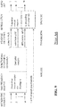
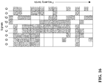
- FIG. 16 shows the distribution of tiles in one time segment.
- each column consists of the tiles of a given audio input signal and each row is a specific frequency interval (corresponding to the tiles).
- the example illustrates five audio objects (represented by the letter o) and two audio channel signals (represented by the letter c).
- the example is based on an encoding of the segment which for each frequency interval may include two downmixes (represented by the letter d).
- the first frequency interval (i.e. the first row) is encoded using only two downmix tiles. Specifically, in this interval, the tiles of the three leftmost objects and the two audio channels may be combined into the first downmix and the tiles of the two rightmost objects may be combined into the second downmix tile.
- next frequency interval/ row all tiles are encoded as non-downmix tiles.
- the two tiles of the two audio channels are downmixed into one downmix tile whereas all object tiles are coded as non-downmix tiles.
- the two tiles of the two rightmost objects are downmixed into one downmix tile whereas all other tiles are coded as non-downmix tiles.
- the quantization level for a given object/ tile can be increased due to spatial masking by other objects/ tiles in the scene. In extreme cases, a given tile may e.g. not be transmitted at all (i.e. quantized to zero).
- the selector 1303 may select tiles for downmixing in response to a target data rate for the encoded audio signal.
- the number of tiles that are downmixed and/or the number of downmixes that are included in the encoded audio signal may be dependent on the available (i.e. the target) data rate.
- the available (i.e. the target) data rate may be dependent on the available (i.e. the target) data rate.
- the target data rate increases, the number of downmixes is reduced, and indeed if the data rate is sufficiently high, the system may select not to perform any downmixes.
- the number of downmixes may be small but each downmix may be a downmix of a high number of tiles.
- a relatively low number of downmixes may represent most (if not all) frequency tiles of the plurality of audio signals.
- the selector 1303 may (also) perform the selection in response to the energy of the tiles. Specifically, tiles that represent lower energy of the signal component in the tile may be downmixed whereas tiles that represent higher energy of the signal component in the tile may be encoded as a non-downmix tile. A lower energy is likely to be less perceptually significant and therefore the implications (such as cross talk) of the downmix encoding may be reduced accordingly. In some scenarios, it may be advantageous to balance the energy of the tiles that are combined in a given downmix. This may for example reduce cross talk as the signals will be more similar in the given tile.
- the selection may be in response to spatial characteristics of the tiles.
- the audio object may represent audio objects that are likely to be positioned close to each other and accordingly these tiles may be selected to be downmixed together.
- objects that are spatially nearby will be combined. The rationale for this is that the more spatial separation is required between objects, the more spatial unmasking will occur. In particular, cross talk is less likely to be perceived when it is between two close audio sources than when it is for two audio sources which are spatially far from each other.
- the selection may be in response to a coherence characteristic between pairs of the tiles. Indeed, cross talk between signals that are closely correlated is less likely to be perceived than between signals that are only very loosely correlated.
- a predetermined restriction may be that the audio objects can only be downmixed together in certain pairs. For example, tiles of object 1 can only be downmixed with tiles (in the same frequency and time interval) of object 2, tiles of object 3 can only be downmixed with tiles of object 4 etc.
- the downmix indication may simply indicate which tiles are downmixed and need not explicitly indicate the identity of tiles that are downmixed in a specific downmix.
- the downmix indication may include one bit for each frequency interval of object 1 and 2 where the bit simply indicates whether the tile is downmixed or not. The decoder may interpret this bit and perform an upmixing of the tile to generate tiles for objects 1 and 2 if the bit indicates that the tile is a downmix.
- the downmix indication need not be explicit but may be provided by other data.
- the indication that a tile is a downmix tile may simply be provided by the presence of parametric upmix data.
- this provides an indication that the tile is indeed a downmix tile.
- the downmix indication may indicate which object tiles are downmixed in a given downmix tile.
- the downmix indication may for one or more (possibly all) tiles that are encoded as downmix tiles provide a link between the downmix tile and the tiles of the audio objects.
- the link may identify the tiles that are downmixed in the downmix.
- the link data may for a given downmix tile indicate that it is a downmix of, say, objects 1 and 2, for another downmix tile that it is a downmix of, say, objects 2, 4 and 7, etc.
- Including identification of object tiles that have been downmixed into downmix tiles may provide increased flexibility and can avoid any need for a predetermined restriction on which tiles may be downmixed.
- the approach may allow a completely free optimization where tiles of the downmixes may be downmixed in any combination to provide an optimized (perceptual) audio quality for a given data rate.
- the downmix indication can be structured differently in different embodiments.
- the downmix indication data may be provided with reference to the original object tiles (more generally the tiles of the audio signals being encoded). For example, for each tile of each object, the presence of parametric upmix data may indicate that the tile is a downmix tile. For this tile, data is provided which links it to a specific encoded downmix tile. For example, the data may provide a pointer to a data position in the encoded data signal where the corresponding downmix tile has been encoded.
- the downmix indication data may be provided with reference to the encoded tiles (and in particular to the encoded downmix tiles of the audio signals).
- the audio signal may include a data section which identifies which objects the downmix tile represents.
- Tile N of object A is downmixed into encoded tile X
- Tile M of object B is downmixed into encoded tile X, (i.e. data referenced to the object tile) provides exactly the same information as data indicating:
- Encoded tile X is a downmix of tile N of object A and tile M of object B. (i.e. data referenced to the encoded tile).
- the arrangement of data in the encoded data signal may depend on the specific embodiment.
- the data representing the downmix indication may be provided in one data section separate from the encoded data tiles and parametric update.
- the data may be interspersed, e.g. with each encoded downmix data tile being accompanied by a field comprising upmix parameters and identification of the object tiles included in the downmix.
- the encoded audio signal may be structured by the object signals being arranged sequentially in a data stream.
- first data may be provided for object 1.
- This data may comprise a plurality of sequential data sections each of which represents one tile (e.g. in order of increasing frequency).
- the first section includes an encoded tile for tile 1 of object 1
- the next section includes an encoded tile for tile 2 of object 1, etc.
- a section comprises an encoded tile that is a non-downmix tile, only the encoded tile data is included in the section.
- the section comprises the encoded downmix data, i.e. the downmix tile.
- the section comprises a field containing parametric upmix parameters for generating the tile for object 1 from the downmix tile. This indicates that the section contains a downmix tile.
- a field is included which identifies which other tile(s) is (are) combined into the downmix (e.g. it may contain data indicating that the corresponding tile of object 2 is also represented by the downmix).
- the encoded audio signal can thus contain sequential sections for all tiles of the first audio object.
- the encoded data for object 2 is provided in a plurality of sections each of which corresponds to one tile.
- downmix encoding data that has already been provided in an earlier section (e.g. for a previous object) is not included.
- this encoded downmix data has already been provided for tile 2 of object 1, and accordingly the data section for tile 2 of object 2 does not contain any encoded data.
- it may comprise the upmix parameters for generating tile 2 of object 2 from the downmix tile.
- this data may not be provided (i.e. blind upmixing may be used) or it may be provided with the encoded tile data (i.e. in the data section for tile 2 of object 1).
- the current section may be empty or skipped.
- encoded downmix data is included only the first time it is encountered in the sequential tile arrangement of the encoded data signal.
- the encoded data for each time segment may be provided as described with time segments being arranged sequentially in the encoded audio signal.
- both audio channels and objects are treated in a similar way as previously described for audio objects.
- the encoder decides upon which tiles of objects and/or channels are to be combined. This selection can specifically combine tiles of audio channels and objects into (hybrid) downmix tiles.
- a decoder can comprise: a receiver for receiving an encoded data signal representing a plurality of audio signals, the encoded data signal comprising encoded time-frequency tiles for the plurality of audio signals, the encoded time-frequency tiles comprising non-downmix time-frequency tiles and downmix time-frequency tiles, each downmix time-frequency tile being a downmix of at least two time-frequency tiles of the plurality of audio signals and each non-downmix time-frequency tile representing only one time-frequency tile of the plurality of audio signals, the encoded data signal further comprising a downmix indication for time-frequency tiles of the plurality of audio signals, the downmix indication indicating whether time-frequency tiles of the plurality of audio signals are encoded as downmix time-frequency tiles or non-downmix time-frequency tiles; a generator for generating a set of output signals from the encoded time-frequency tiles, the generation of the output signals comprising an upmixing for encoded time-frequency tiles that are indicated by the downmix indication to be downmix time-frequency tiles.
- An encoder can comprise: a receiver for receiving a plurality of audio signals, each audio signal comprising a plurality of time-frequency tiles; a selector for selecting a first subset of the plurality of time-frequency tiles to be downmixed; a downmixer for downmixing time-frequency tiles of the first subset to generate downmixed time-frequency tiles; a first encoder for generating downmix encoded time-frequency tiles by encoding the downmix time-frequency tiles; a second encoder for generating non-downmix time-frequency tiles by encoding a second subset of the time-frequency tiles of the audio signals without downmixing of time-frequency tiles of the second subset; a unit for generating a downmix indication indicating whether time-frequency tiles of the first subset and the second subset are encoded as downmix encoded time-frequency tiles or as non-downmix time-frequency tiles; an output for generating an encoded audio signal representing the plurality of audio signals, the encoded audio signal comprising the non-downmix time-frequency tiles,
- An encoded data signal representing a plurality of audio signals can comprise: encoded time-frequency tiles for the plurality of audio objects, the encoded time-frequency tiles comprising non-downmix time-frequency tiles and downmix time-frequency tiles, each downmix time-frequency tile being a downmix of at least two time-frequency tiles of the plurality of audio objects and each non-downmix time-frequency tile representing only one time-frequency tile of the plurality of audio objects, the encoded data signal further comprising a downmix indication for time-frequency tiles of the plurality of audio objects, the downmix indication indicating whether time-frequency tiles of the plurality of audio objects are encoded as downmix time-frequency tiles or non-downmix time-frequency tiles.
- the invention can be implemented in any suitable form including hardware, software, firmware or any combination of these.
- the invention may optionally be implemented at least partly as computer software running on one or more data processors and/or digital signal processors.
- the elements and components of an embodiment of the invention may be physically, functionally and logically implemented in any suitable way. Indeed the functionality may be implemented in a single unit, in a plurality of units or as part of other functional units. As such, the invention may be implemented in a single unit or may be physically and functionally distributed between different units, circuits and processors.
Applications Claiming Priority (3)
| Application Number | Priority Date | Filing Date | Title |
|---|---|---|---|
| US201261669197P | 2012-07-09 | 2012-07-09 | |
| EP13762579.4A EP2870603B1 (de) | 2012-07-09 | 2013-07-09 | Codierung und decodierung von audiosignalen |
| PCT/IB2013/055628 WO2014009878A2 (en) | 2012-07-09 | 2013-07-09 | Encoding and decoding of audio signals |
Related Parent Applications (2)
| Application Number | Title | Priority Date | Filing Date |
|---|---|---|---|
| EP13762579.4A Division-Into EP2870603B1 (de) | 2012-07-09 | 2013-07-09 | Codierung und decodierung von audiosignalen |
| EP13762579.4A Division EP2870603B1 (de) | 2012-07-09 | 2013-07-09 | Codierung und decodierung von audiosignalen |
Publications (1)
| Publication Number | Publication Date |
|---|---|
| EP3748632A1 true EP3748632A1 (de) | 2020-12-09 |
Family
ID=49170767
Family Applications (2)
| Application Number | Title | Priority Date | Filing Date |
|---|---|---|---|
| EP20182398.6A Withdrawn EP3748632A1 (de) | 2012-07-09 | 2013-07-09 | Codierung und decodierung von audiosignalen |
| EP13762579.4A Active EP2870603B1 (de) | 2012-07-09 | 2013-07-09 | Codierung und decodierung von audiosignalen |
Family Applications After (1)
| Application Number | Title | Priority Date | Filing Date |
|---|---|---|---|
| EP13762579.4A Active EP2870603B1 (de) | 2012-07-09 | 2013-07-09 | Codierung und decodierung von audiosignalen |
Country Status (9)
| Country | Link |
|---|---|
| US (1) | US9478228B2 (de) |
| EP (2) | EP3748632A1 (de) |
| JP (1) | JP6231093B2 (de) |
| CN (1) | CN104428835B (de) |
| BR (1) | BR112015000247B1 (de) |
| MX (1) | MX342150B (de) |
| RU (1) | RU2643644C2 (de) |
| WO (1) | WO2014009878A2 (de) |
| ZA (1) | ZA201500888B (de) |
Families Citing this family (17)
| Publication number | Priority date | Publication date | Assignee | Title |
|---|---|---|---|---|
| US9489954B2 (en) * | 2012-08-07 | 2016-11-08 | Dolby Laboratories Licensing Corporation | Encoding and rendering of object based audio indicative of game audio content |
| EP3961622B1 (de) * | 2013-05-24 | 2023-11-01 | Dolby International AB | Audiocodierer |
| US9774974B2 (en) | 2014-09-24 | 2017-09-26 | Electronics And Telecommunications Research Institute | Audio metadata providing apparatus and method, and multichannel audio data playback apparatus and method to support dynamic format conversion |
| TWI587286B (zh) | 2014-10-31 | 2017-06-11 | 杜比國際公司 | 音頻訊號之解碼和編碼的方法及系統、電腦程式產品、與電腦可讀取媒體 |
| US11223857B2 (en) * | 2015-06-02 | 2022-01-11 | Sony Corporation | Transmission device, transmission method, media processing device, media processing method, and reception device |
| US10693936B2 (en) * | 2015-08-25 | 2020-06-23 | Qualcomm Incorporated | Transporting coded audio data |
| US9961467B2 (en) * | 2015-10-08 | 2018-05-01 | Qualcomm Incorporated | Conversion from channel-based audio to HOA |
| US9854375B2 (en) * | 2015-12-01 | 2017-12-26 | Qualcomm Incorporated | Selection of coded next generation audio data for transport |
| CN112218211B (zh) | 2016-03-15 | 2022-06-07 | 弗劳恩霍夫应用研究促进协会 | 用于生成声场描述的装置、方法或计算机程序 |
| CN110447243B (zh) | 2017-03-06 | 2021-06-01 | 杜比国际公司 | 基于音频数据流渲染音频输出的方法、解码器系统和介质 |
| US9820073B1 (en) | 2017-05-10 | 2017-11-14 | Tls Corp. | Extracting a common signal from multiple audio signals |
| GB2587614A (en) * | 2019-09-26 | 2021-04-07 | Nokia Technologies Oy | Audio encoding and audio decoding |
| JP2022083443A (ja) * | 2020-11-24 | 2022-06-03 | ネイバー コーポレーション | オーディオと関連してユーザカスタム型臨場感を実現するためのコンピュータシステムおよびその方法 |
| JP2022083445A (ja) * | 2020-11-24 | 2022-06-03 | ネイバー コーポレーション | ユーザカスタム型臨場感を実現するためのオーディオコンテンツを製作するコンピュータシステムおよびその方法 |
| KR102508815B1 (ko) * | 2020-11-24 | 2023-03-14 | 네이버 주식회사 | 오디오와 관련하여 사용자 맞춤형 현장감 실현을 위한 컴퓨터 시스템 및 그의 방법 |
| KR20230165855A (ko) * | 2021-04-08 | 2023-12-05 | 노키아 테크놀로지스 오와이 | 공간 오디오 객체 분리 |
| CN115552518A (zh) * | 2021-11-02 | 2022-12-30 | 北京小米移动软件有限公司 | 一种信号编解码方法、装置、用户设备、网络侧设备及存储介质 |
Citations (3)
| Publication number | Priority date | Publication date | Assignee | Title |
|---|---|---|---|---|
| US20050058304A1 (en) * | 2001-05-04 | 2005-03-17 | Frank Baumgarte | Cue-based audio coding/decoding |
| US20070174062A1 (en) * | 2006-01-20 | 2007-07-26 | Microsoft Corporation | Complex-transform channel coding with extended-band frequency coding |
| US20110038423A1 (en) * | 2009-08-12 | 2011-02-17 | Samsung Electronics Co., Ltd. | Method and apparatus for encoding/decoding multi-channel audio signal by using semantic information |
Family Cites Families (19)
| Publication number | Priority date | Publication date | Assignee | Title |
|---|---|---|---|---|
| MXPA06011361A (es) * | 2004-04-05 | 2007-01-16 | Koninkl Philips Electronics Nv | Codificador de canales multiples. |
| US8345899B2 (en) * | 2006-05-17 | 2013-01-01 | Creative Technology Ltd | Phase-amplitude matrixed surround decoder |
| US9014377B2 (en) * | 2006-05-17 | 2015-04-21 | Creative Technology Ltd | Multichannel surround format conversion and generalized upmix |
| US9565509B2 (en) * | 2006-10-16 | 2017-02-07 | Dolby International Ab | Enhanced coding and parameter representation of multichannel downmixed object coding |
| CN101490745B (zh) * | 2006-11-24 | 2013-02-27 | Lg电子株式会社 | 用于编码和解码基于对象的音频信号的方法和装置 |
| AU2007322488B2 (en) * | 2006-11-24 | 2010-04-29 | Lg Electronics Inc. | Method for encoding and decoding object-based audio signal and apparatus thereof |
| JP2008252834A (ja) * | 2007-03-30 | 2008-10-16 | Toshiba Corp | 音声再生装置 |
| US8612237B2 (en) * | 2007-04-04 | 2013-12-17 | Apple Inc. | Method and apparatus for determining audio spatial quality |
| MX2010004220A (es) * | 2007-10-17 | 2010-06-11 | Fraunhofer Ges Forschung | Codificacion de audio usando mezcla descendente. |
| KR101221916B1 (ko) * | 2008-01-01 | 2013-01-15 | 엘지전자 주식회사 | 오디오 신호 처리 방법 및 장치 |
| KR101596504B1 (ko) * | 2008-04-23 | 2016-02-23 | 한국전자통신연구원 | 객체기반 오디오 컨텐츠의 생성/재생 방법 및 객체기반 오디오 서비스를 위한 파일 포맷 구조를 가진 데이터를 기록한 컴퓨터 판독 가능 기록 매체 |
| EP2312578A4 (de) * | 2008-07-11 | 2012-09-12 | Nec Corp | Signalanalysevorrichtung, signalsteuerungsvorrichtung sowie verfahren und programm dafür |
| CN102016982B (zh) * | 2009-02-04 | 2014-08-27 | 松下电器产业株式会社 | 结合装置、远程通信系统以及结合方法 |
| KR101387902B1 (ko) * | 2009-06-10 | 2014-04-22 | 한국전자통신연구원 | 다객체 오디오 신호를 부호화하는 방법 및 부호화 장치, 복호화 방법 및 복호화 장치, 그리고 트랜스코딩 방법 및 트랜스코더 |
| RU2558612C2 (ru) * | 2009-06-24 | 2015-08-10 | Фраунхофер-Гезелльшафт Цур Фердерунг Дер Ангевандтен Форшунг Е.Ф. | Декодер аудиосигнала, способ декодирования аудиосигнала и компьютерная программа с использованием ступеней каскадной обработки аудиообъектов |
| MY165328A (en) * | 2009-09-29 | 2018-03-21 | Fraunhofer Ges Forschung | Audio signal decoder, audio signal encoder, method for providing an upmix signal representation, method for providing a downmix signal representation, computer program and bitstream using a common inter-object-correlation parameter value |
| KR101666465B1 (ko) * | 2010-07-22 | 2016-10-17 | 삼성전자주식회사 | 다채널 오디오 신호 부호화/복호화 장치 및 방법 |
| KR20140027954A (ko) * | 2011-03-16 | 2014-03-07 | 디티에스, 인코포레이티드 | 3차원 오디오 사운드트랙의 인코딩 및 재현 |
| KR20130093798A (ko) * | 2012-01-02 | 2013-08-23 | 한국전자통신연구원 | 다채널 신호 부호화 및 복호화 장치 및 방법 |
-
2013
- 2013-07-09 CN CN201380036886.9A patent/CN104428835B/zh active Active
- 2013-07-09 MX MX2015000113A patent/MX342150B/es active IP Right Grant
- 2013-07-09 EP EP20182398.6A patent/EP3748632A1/de not_active Withdrawn
- 2013-07-09 WO PCT/IB2013/055628 patent/WO2014009878A2/en active Application Filing
- 2013-07-09 EP EP13762579.4A patent/EP2870603B1/de active Active
- 2013-07-09 BR BR112015000247-1A patent/BR112015000247B1/pt active IP Right Grant
- 2013-07-09 RU RU2015104074A patent/RU2643644C2/ru active
- 2013-07-09 JP JP2015521121A patent/JP6231093B2/ja active Active
- 2013-07-09 US US14/413,234 patent/US9478228B2/en active Active
-
2015
- 2015-02-06 ZA ZA2015/00888A patent/ZA201500888B/en unknown
Patent Citations (3)
| Publication number | Priority date | Publication date | Assignee | Title |
|---|---|---|---|---|
| US20050058304A1 (en) * | 2001-05-04 | 2005-03-17 | Frank Baumgarte | Cue-based audio coding/decoding |
| US20070174062A1 (en) * | 2006-01-20 | 2007-07-26 | Microsoft Corporation | Complex-transform channel coding with extended-band frequency coding |
| US20110038423A1 (en) * | 2009-08-12 | 2011-02-17 | Samsung Electronics Co., Ltd. | Method and apparatus for encoding/decoding multi-channel audio signal by using semantic information |
Non-Patent Citations (2)
| Title |
|---|
| BOSI M ET AL: "ISO/IEC MPEG-2 ADVANCED AUDIO CODING", JOURNAL OF THE AUDIO ENGINEERING SOCIETY, AUDIO ENGINEERING SOCIETY, NEW YORK, NY, US, vol. 45, no. 10, 1 October 1997 (1997-10-01), pages 789 - 812, XP000730161, ISSN: 1549-4950 * |
| M. KELLY: "The continuity illusion revisited: coding of multiple concurrent sound sources", PROC.MPCA-2002, 15 November 2002 (2002-11-15) |
Also Published As
| Publication number | Publication date |
|---|---|
| RU2643644C2 (ru) | 2018-02-02 |
| EP2870603A2 (de) | 2015-05-13 |
| JP2015527609A (ja) | 2015-09-17 |
| US9478228B2 (en) | 2016-10-25 |
| MX2015000113A (es) | 2015-08-10 |
| BR112015000247B1 (pt) | 2021-08-03 |
| CN104428835B (zh) | 2017-10-31 |
| EP2870603B1 (de) | 2020-09-30 |
| ZA201500888B (en) | 2017-01-25 |
| WO2014009878A2 (en) | 2014-01-16 |
| US20150142453A1 (en) | 2015-05-21 |
| JP6231093B2 (ja) | 2017-11-15 |
| WO2014009878A3 (en) | 2014-03-13 |
| CN104428835A (zh) | 2015-03-18 |
| RU2015104074A (ru) | 2016-08-27 |
| BR112015000247A2 (pt) | 2017-06-27 |
| MX342150B (es) | 2016-09-15 |
Similar Documents
| Publication | Publication Date | Title |
|---|---|---|
| EP2870603B1 (de) | Codierung und decodierung von audiosignalen | |
| US10770080B2 (en) | Audio decoder, audio encoder, method for providing at least four audio channel signals on the basis of an encoded representation, method for providing an encoded representation on the basis of at least four audio channel signals and computer program using a bandwidth extension | |
| US9966080B2 (en) | Audio object encoding and decoding | |
| JP5081838B2 (ja) | オーディオ符号化及び復号 | |
| JP5171622B2 (ja) | マルチチャンネルオーディオ信号の生成 | |
| TWI490853B (zh) | 多聲道音訊處理技術 | |
| KR102517867B1 (ko) | 오디오 디코더 및 디코딩 방법 | |
| EP3468074A1 (de) | Verfahren und vorrichtung zur decodierung einer ambisonic-darstellung eines 2- oder 3-dimensionalen schallfeldes | |
| RU2659497C2 (ru) | Управляемое модулем рендеринга пространственное повышающее микширование | |
| CN107077861B (zh) | 音频编码器和解码器 | |
| KR20180042397A (ko) | 프레젠테이션 변환 파라미터들을 사용하는 오디오 인코딩 및 디코딩 | |
| JP6888172B2 (ja) | 音場表現信号を符号化する方法及びデバイス |
Legal Events
| Date | Code | Title | Description |
|---|---|---|---|
| PUAI | Public reference made under article 153(3) epc to a published international application that has entered the european phase |
Free format text: ORIGINAL CODE: 0009012 |
|
| STAA | Information on the status of an ep patent application or granted ep patent |
Free format text: STATUS: THE APPLICATION HAS BEEN PUBLISHED |
|
| AC | Divisional application: reference to earlier application |
Ref document number: 2870603 Country of ref document: EP Kind code of ref document: P |
|
| AK | Designated contracting states |
Kind code of ref document: A1 Designated state(s): AL AT BE BG CH CY CZ DE DK EE ES FI FR GB GR HR HU IE IS IT LI LT LU LV MC MK MT NL NO PL PT RO RS SE SI SK SM TR |
|
| STAA | Information on the status of an ep patent application or granted ep patent |
Free format text: STATUS: REQUEST FOR EXAMINATION WAS MADE |
|
| 17P | Request for examination filed |
Effective date: 20210609 |
|
| RBV | Designated contracting states (corrected) |
Designated state(s): AL AT BE BG CH CY CZ DE DK EE ES FI FR GB GR HR HU IE IS IT LI LT LU LV MC MK MT NL NO PL PT RO RS SE SI SK SM TR |
|
| STAA | Information on the status of an ep patent application or granted ep patent |
Free format text: STATUS: EXAMINATION IS IN PROGRESS |
|
| 17Q | First examination report despatched |
Effective date: 20221122 |
|
| STAA | Information on the status of an ep patent application or granted ep patent |
Free format text: STATUS: THE APPLICATION HAS BEEN WITHDRAWN |
|
| 18W | Application withdrawn |
Effective date: 20230403 |