EP3748442A1 - Numerical control device - Google Patents
Numerical control device Download PDFInfo
- Publication number
- EP3748442A1 EP3748442A1 EP20177550.9A EP20177550A EP3748442A1 EP 3748442 A1 EP3748442 A1 EP 3748442A1 EP 20177550 A EP20177550 A EP 20177550A EP 3748442 A1 EP3748442 A1 EP 3748442A1
- Authority
- EP
- European Patent Office
- Prior art keywords
- program
- machining
- stop
- stop condition
- command
- Prior art date
- Legal status (The legal status is an assumption and is not a legal conclusion. Google has not performed a legal analysis and makes no representation as to the accuracy of the status listed.)
- Granted
Links
Images




Classifications
-
- G—PHYSICS
- G05—CONTROLLING; REGULATING
- G05B—CONTROL OR REGULATING SYSTEMS IN GENERAL; FUNCTIONAL ELEMENTS OF SUCH SYSTEMS; MONITORING OR TESTING ARRANGEMENTS FOR SUCH SYSTEMS OR ELEMENTS
- G05B19/00—Program-control systems
- G05B19/02—Program-control systems electric
- G05B19/18—Numerical control [NC], i.e. automatically operating machines, in particular machine tools, e.g. in a manufacturing environment, so as to execute positioning, movement or co-ordinated operations by means of program data in numerical form
-
- G—PHYSICS
- G05—CONTROLLING; REGULATING
- G05B—CONTROL OR REGULATING SYSTEMS IN GENERAL; FUNCTIONAL ELEMENTS OF SUCH SYSTEMS; MONITORING OR TESTING ARRANGEMENTS FOR SUCH SYSTEMS OR ELEMENTS
- G05B19/00—Program-control systems
- G05B19/02—Program-control systems electric
- G05B19/18—Numerical control [NC], i.e. automatically operating machines, in particular machine tools, e.g. in a manufacturing environment, so as to execute positioning, movement or co-ordinated operations by means of program data in numerical form
- G05B19/4155—Numerical control [NC], i.e. automatically operating machines, in particular machine tools, e.g. in a manufacturing environment, so as to execute positioning, movement or co-ordinated operations by means of program data in numerical form characterised by program execution, i.e. part program or machine function execution, e.g. selection of a program
-
- G—PHYSICS
- G05—CONTROLLING; REGULATING
- G05B—CONTROL OR REGULATING SYSTEMS IN GENERAL; FUNCTIONAL ELEMENTS OF SUCH SYSTEMS; MONITORING OR TESTING ARRANGEMENTS FOR SUCH SYSTEMS OR ELEMENTS
- G05B19/00—Program-control systems
- G05B19/02—Program-control systems electric
- G05B19/18—Numerical control [NC], i.e. automatically operating machines, in particular machine tools, e.g. in a manufacturing environment, so as to execute positioning, movement or co-ordinated operations by means of program data in numerical form
- G05B19/406—Numerical control [NC], i.e. automatically operating machines, in particular machine tools, e.g. in a manufacturing environment, so as to execute positioning, movement or co-ordinated operations by means of program data in numerical form characterised by monitoring or safety
- G05B19/4068—Verifying part program on screen, by drawing or other means
-
- G—PHYSICS
- G05—CONTROLLING; REGULATING
- G05B—CONTROL OR REGULATING SYSTEMS IN GENERAL; FUNCTIONAL ELEMENTS OF SUCH SYSTEMS; MONITORING OR TESTING ARRANGEMENTS FOR SUCH SYSTEMS OR ELEMENTS
- G05B2219/00—Program-control systems
- G05B2219/30—Nc systems
- G05B2219/34—Director, elements to supervisory
- G05B2219/34393—Stop program if needed workpiece, tool or data lacks, misses
-
- G—PHYSICS
- G05—CONTROLLING; REGULATING
- G05B—CONTROL OR REGULATING SYSTEMS IN GENERAL; FUNCTIONAL ELEMENTS OF SUCH SYSTEMS; MONITORING OR TESTING ARRANGEMENTS FOR SUCH SYSTEMS OR ELEMENTS
- G05B2219/00—Program-control systems
- G05B2219/30—Nc systems
- G05B2219/34—Director, elements to supervisory
- G05B2219/34394—Execute a certain number of program blocks and stop
-
- Y—GENERAL TAGGING OF NEW TECHNOLOGICAL DEVELOPMENTS; GENERAL TAGGING OF CROSS-SECTIONAL TECHNOLOGIES SPANNING OVER SEVERAL SECTIONS OF THE IPC; TECHNICAL SUBJECTS COVERED BY FORMER USPC CROSS-REFERENCE ART COLLECTIONS [XRACs] AND DIGESTS
- Y02—TECHNOLOGIES OR APPLICATIONS FOR MITIGATION OR ADAPTATION AGAINST CLIMATE CHANGE
- Y02P—CLIMATE CHANGE MITIGATION TECHNOLOGIES IN THE PRODUCTION OR PROCESSING OF GOODS
- Y02P90/00—Enabling technologies with a potential contribution to greenhouse gas [GHG] emissions mitigation
- Y02P90/02—Total factory control, e.g. smart factories, flexible manufacturing systems [FMS] or integrated manufacturing systems [IMS]
Definitions
- the present invention relates to a numerical control device.
- a numerical control device for controlling a machine tool has a function to stop the execution of a program in the middle of the running of the program in order to perform validation of the program.
- Japanese Unexamined Patent Application, Publication No. 2015-79344 discloses a function of smoothly performing validation by pausing the execution of the program immediately after sub program call or macro call.
- the sub program is a program in which operations such as a fixed operation and a repetitive operation are registered. It becomes possible to easily describe the program by using the sub program call in a main program.
- the macro call is a function that enables the sub program to specify arguments to realize more versatile call.
- Fig. 5 shows an example of the sub program call function.
- the "M98P100L2A_B_" block calls the subprogram "O100(SUB)" in the main program "O0001(MAIN)".
- Fig. 6 shows an example of the macro call function.
- A1. 0 and B2. 0 of the G65 block are handed over to 09010 as arguments, and become variables of the macro variable #1 and the macro variable #2.
- the macro call by G65 is referred to as a simple call, and performing the same macro call as G65 by a G code which is registered in advance (not shown) is referred to as macro call by G code.
- the sequence number comparison function is a function to stop automatic operation when the block matching the program number and sequence number set in advance is executed.
- Fig. 7 shows an example of a sequence number comparison stop function.
- the automatic operation is stopped at the time the block of "N11G00X40. Y40.” is executed, and the setting of the sequence number is -1 (function disabled).
- Patent Document 1 Japanese Unexamined Patent Application, Publication No. 2015-79344
- the program stop function disclosed in Japanese Unexamined Patent Application, Publication No. 2015-79344 can only handle the first time of the sub program call. Therefore, in a case of a machining program that calls sub programs multiple times from the main program in order to specify the part machining shapes by the sub programs and continuously machine the plurality of the parts, in order to stop at the block of a specified N number after machining of the X-th part (X is a natural number of 2 or more), it is necessary to set the abovementioned sequence number comparison stop function after the execution of the block of the specified N number of the (X-1)-th part, or to count the number of times of the sub program call manually, and thus, it is necessary to manually set complicated processing.
- a numerical control device that operates in accordance with a command program, includes: a program analysis section that, upon executing a command program for continuously machining a plurality of parts, analyzes the command program; an analyzed program execution unit that executes the command program analyzed by the program analysis section; a program stop condition setting section that sets a program stop condition in the command program on a basis of a machining stop condition for stopping the continuous machining specified by a user; a program stop determining section that determines whether an execution block of the command program satisfies the program stop condition on a basis of an analysis result of the command program by the program analysis section; and a program stop requesting section that, in a case in which the program stop determining section determines that the execution block of the command program satisfies the program stop condition, outputs an execution block stop request of the command program to the analyzed program execution unit.
- Fig. 1 shows the overall configuration of a numerical control device according to the first embodiment.
- Fig. 2 is a flowchart showing the operation of the numerical control device 1.
- the numerical control device 1 according to the first embodiment is a device that sets a program stop condition corresponding to the machining stop condition to finish machining at a position where machining is completed at the part immediately before the remaining amount of consumables such as wires runs out.
- the numerical control device 1 includes a command program analysis unit 11, a program stop unit 12, an analyzed program execution unit 13, and a check drawing display unit 14.
- the command program analysis unit 11 includes a program analysis section 111, a call determining section 112, and a call executing section 113.
- the program analysis section 111 analyzes the command program at the time of executing the command program. In the first embodiment, the program analysis section 111 analyzes the command program for continuously machining a plurality of parts.
- the call determining section 112 determines macro call or sub program call on the basis of the analysis result of the command program by the program analysis section 111.
- the call executing section 113 executes a macro call or a subprogram call determined to be invoked by the call determining section 112.
- the program stop unit 12 includes a program stop condition setting section 121, a program stop determining section 122, and a program stop requesting section 123.
- the program stop condition setting section 121 sets a program stop condition including the number of blocks from the head of the program of the command program corresponding to the machining stop condition to the stop block.
- the program stop condition setting section 121 acquires the remaining distance X km of the wire recorded in the memory (not shown) of the numerical control device 1.
- the program stop condition setting section 121 acquires the distance Y km of the wire required to machine one part recorded in the memory of the numerical control device 1.
- the program stop condition setting section 121 calculates the number Z pieces that can be machined by the remaining wire on the basis of the remaining distance X km of the wire and the distance Y km of the wire required for machining.
- the program stop condition setting section 121 calculates, as the program stop condition, the number of blocks from the head of the program when machining of the remaining Z pieces is finished to the stop block (for example, a block such as G40, which is a code for ending the diameter compensation, or a wire cutting instruction M60), and sets a program stop condition including the number of the blocks.
- the stop block for example, a block such as G40, which is a code for ending the diameter compensation, or a wire cutting instruction M60
- the program stop determining section 122 determines whether or not the execution block of the command program satisfies the program stop condition on the basis of the analysis result of the command program by the program analysis section 111. If it is determined as YES, the program stop is requested to the program stop requesting section 123.
- the program stop requesting section 123 outputs an execution block stop request of the command program to the analyzed program execution unit 13.
- the analyzed program execution unit 13 executes the command program analyzed by the program analysis section 111.
- the analyzed program execution unit 13 upon acquiring the execution block stop request from the program stop requesting section 123, the analyzed program execution unit 13 stops the execution of the command program in the block that has been requested.
- the check drawing display unit 14 acquires information for drawing the machining path commanded by the command program from the analyzed program execution unit 13, and displays the machining path on a display device (not shown).
- the display device may include a touch screen which allows the user to select the machining shape of each of the parts by touching the screen of the display device.
- the numerical control device 1 includes general functional blocks such as a functional block for controlling a machine tool, a functional block for performing communication, and a functional block for accepting operations from a user.
- these general functional blocks are well known to those skilled in the art, and thus are not shown or explained.
- Fig. 2 is a flowchart showing the operation of the numerical control device 1.
- the program stop condition setting section 121 sets the program stop condition.
- the program stop condition setting section 121 calculates the number Z pieces that can be machined by the remaining wire on the basis of the remaining distance X km of the wire and the distance Y km of the wire required to machine one part, followed by calculating, as the program stop condition, the number of the blocks from the head of the program when machining of the remaining Z pieces is completed to the stop block (for example, a block such as G40, which is a code for ending the diameter compensation, or a wire cutting instruction M60).
- Step S12 the program stop determining section 122 determines whether or not the execution block of the command program satisfies the program stop condition. If it is determined as YES (S12: YES), the processing advances to Step S13. If it is determined as NO (NO: S12), the processing returns to Step S12.
- Step S13 the program stop determining section 122 requests the program stop to the program stop requesting section 123, and the program stop requesting section 123 outputs an execution block stop request of the command program to the analyzed program execution unit 13.
- the numerical control device 1 includes: a program stop condition setting section 121 that sets a program stop condition in the command program on a basis of a machining stop condition for stopping the continuous machining specified by a user; a program stop determining section 122 that determines whether an execution block of the command program satisfies the program stop condition on a basis of an analysis result of the command program; and a program stop requesting section 123 that, in a case in which it is determined that the execution block of the command program satisfies the program stop condition, outputs an execution block stop request of the command program to the analyzed program execution unit.
- the program stop condition setting section 121 sets a program stop condition including a number of blocks from a program head of the command program corresponding to the machining stop condition to a stop block.
- Fig. 3 shows an example of a display screen at the time of multi-piece machining provided in the numerical control device 1 according to the second embodiment.
- a numerical control device 1A specifies a specific position among the machining shapes of the unmachined portion of the check drawing path by a user through a touch screen or the like of the display screen provided in the numerical control device 1A, and sets a program stop condition corresponding to the machining stop condition that stops machining at this specified position.
- the machined machining path is shown as a solid line and the unmachined machining path is shown as a dotted line.
- the present invention is not limited thereto, and the machined machining path may be shown as a dotted line and the unmachined machining path as a solid line.
- the black circles are shown as machining start points, and it is also possible to stop machining after machining. The user selects a machining position at which it is desired to stop machining from among a plurality of machining shapes.
- Fig. 3 shows an example of the machining path drawing screen for performing multi-piece machining on the square parts having two rows vertically and five columns horizontally.
- the machining path of the second part under machining is indicated by a solid line, and the machining path of the subsequent part is indicated by a dotted line.
- the setting to stop after machining the fifth part is performed.
- the numerical control device 1A according to the second embodiment and the numerical control device 1 according to the first embodiment differ from each other in the machining stop condition and the program stop condition, the configurations therebetween are the same. Therefore, illustration and explanation thereof are omitted.
- the program stop condition setting section 121 sets a program stop condition including the number of blocks from a program head of the command program corresponding to the machining stop condition to the stop block when machining of a predetermined machining shape is finished.
- the program stop condition setting section 121 calculates the machining shape of what number the shape is when the user specifies the machining shape of the unmachined portion of the check drawing path by a touch screen. As a result, it is calculated as the X-th machining shape.
- the program stop condition setting section 121 calculates, as the program stop condition, the number of blocks from the program head when machining of the machining shape of the remaining X-th piece is finished to the stop block (for example, a block such as G40, which is for ending the diameter compensation, or a wire cutting instruction M60).
- the program stop condition setting section 121 sets a program stop condition including the number of blocks from the program head of the program corresponding to the machining stop condition to the stop block when machining of a predetermined machining shape is finished.
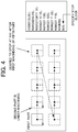
- Fig. 4 shows an example of a display screen and a machining program at the time of multi-piece machining in a numerical control device 1B according to the third embodiment.
- the numerical control device 1B sets the program stop condition corresponding to the machining stop condition to finish machining at the position of the N number. For example, in a case in which the specified number of times is twice, and the specified N number is N11, if the block of N11 is executed for the first time in the machining program, the execution of the program is not stopped, and the execution of the program is stopped if N11 appears at the second time.
- the program stop condition setting section 121 calculates the remaining number of times of the block of N11 and sets the number of times of the N-number block as a stop condition so as to stop at the block of N11 subsequent to the block of N11 at the time of the final machining of the fourth part.
- the program stop condition setting section 121 sets the stop condition so as to stop at the N number block of the specified number of times from the program head in order to stop at the N number block of the specified number of times.
- the Y-th processing e.g., the first finishing processing
- the Y-th processing of the X-th part can be specified and stopped.
- the sequence number comparison stop function after the execution of the specified (Y-1)-th N number block of the X-th part.
- a numerical control device 1C In a case in which a specific N number appears for the specified number of times in the machining program, a numerical control device 1C according to the fourth embodiment skips the N number, and sets the program stop condition corresponding to the machining stop condition to stop machining at the location of the next N number.
- the program stop condition setting section 121 calculates the number of blocks from the program head and sets the program stop condition including the number of the blocks so as to stop at the block of N11 at the next time of the block of N11 at the time of first machining the fifth part. It may be configured not to calculate the number of blocks from the program head, and have variables for counting the number of times of the block of N11 to a numerical control device to compare conditions as to whether to stop machining.
- the program stop condition setting section 121 skips the block of the N number of the specified number of times, and sets the program stop condition including the number of blocks from the program head for stopping at the block of the N number at the next time.
- the processing at the next time of the Y-th processing (e.g., the first finishing processing) of the X-th part can be specified and stopped.
- the sequence number comparison stop function after the execution of the specified (Y)-th N number block of the X-th part.
- the setting of the program stop condition is not limited to the case in which call of a sub program or the like exists.
- it is also applicable to a case in which there is no sub program and only the main program exists.
- the present invention is not limited to the embodiments described above. Furthermore, the effects described in the present embodiment are only the most preferable effects produced from the present invention, and the effects according to the present invention are not limited to those described in the present embodiment.
Landscapes
- Engineering & Computer Science (AREA)
- Human Computer Interaction (AREA)
- Manufacturing & Machinery (AREA)
- Physics & Mathematics (AREA)
- General Physics & Mathematics (AREA)
- Automation & Control Theory (AREA)
- Numerical Control (AREA)
Abstract
Description
- The present invention relates to a numerical control device.
- A numerical control device for controlling a machine tool has a function to stop the execution of a program in the middle of the running of the program in order to perform validation of the program.
- For example, Japanese Unexamined Patent Application, Publication No.
2015-79344 - Here, the sub program is a program in which operations such as a fixed operation and a repetitive operation are registered. It becomes possible to easily describe the program by using the sub program call in a main program. Furthermore, the macro call is a function that enables the sub program to specify arguments to realize more versatile call.
-
Fig. 5 shows an example of the sub program call function. The "M98P100L2A_B_" block calls the subprogram "O100(SUB)" in the main program "O0001(MAIN)". -
Fig. 6 shows an example of the macro call function. InFig. 6 , A1. 0 and B2. 0 of the G65 block are handed over to 09010 as arguments, and become variables of themacro variable # 1 and themacro variable # 2. The macro call by G65 is referred to as a simple call, and performing the same macro call as G65 by a G code which is registered in advance (not shown) is referred to as macro call by G code. - Furthermore, as another program stop function, there is a sequence number comparison function. The sequence number comparison function is a function to stop automatic operation when the block matching the program number and sequence number set in advance is executed.
-
Fig. 7 shows an example of a sequence number comparison stop function. InFig. 7 , in a case in which "1" is specified as the program number that is desired to be stop from among the unmachined portions of the machining program before or during machining, and "11" is specified as the sequence number that is desired to be stopped, the automatic operation is stopped at the time the block of "N11G00X40. Y40." is executed, and the setting of the sequence number is -1 (function disabled). - Patent Document 1: Japanese Unexamined Patent Application, Publication No.
2015-79344 - However, the program stop function disclosed in Japanese Unexamined Patent Application, Publication No.
2015-79344 - In view of the above, it is an object of the present invention to provide a numerical control device that can stop automatic operation after machining of a specific part without the need to manually modify a machining program or to perform macro computation.
- According to an aspect of the present disclosure, a numerical control device that operates in accordance with a command program, includes: a program analysis section that, upon executing a command program for continuously machining a plurality of parts, analyzes the command program; an analyzed program execution unit that executes the command program analyzed by the program analysis section; a program stop condition setting section that sets a program stop condition in the command program on a basis of a machining stop condition for stopping the continuous machining specified by a user; a program stop determining section that determines whether an execution block of the command program satisfies the program stop condition on a basis of an analysis result of the command program by the program analysis section; and a program stop requesting section that, in a case in which the program stop determining section determines that the execution block of the command program satisfies the program stop condition, outputs an execution block stop request of the command program to the analyzed program execution unit.
- According to one aspect, it is possible to stop automatic operation after machining of a specific part without the need to manually modify a machining program or to perform macro calculation.
-
-
Fig. 1 is a diagram showing the configuration of a numerical control device of an embodiment; -
Fig. 2 is a flowchart showing the operation of the numerical control device of an embodiment; -
Fig. 3 is a diagram showing an example of a display screen at the time of multi-piece machining in the numerical control device of an embodiment; -
Fig. 4 is a diagram showing an example of a display screen and a machining program at the time of multi-piece machining in the numerical control device of an embodiment; -
Fig. 5 is a diagram showing an example of a sub program call function; -
Fig. 6 is a diagram showing an example of a macro call function; and -
Fig. 7 is a diagram showing an example of a sequence number comparison function. - Hereinafter, a first embodiment of the present invention will be described with reference to
Figs. 1 and2 .Fig. 1 shows the overall configuration of a numerical control device according to the first embodiment.Fig. 2 is a flowchart showing the operation of thenumerical control device 1. Thenumerical control device 1 according to the first embodiment is a device that sets a program stop condition corresponding to the machining stop condition to finish machining at a position where machining is completed at the part immediately before the remaining amount of consumables such as wires runs out. - As shown in
Fig. 1 , thenumerical control device 1 includes a commandprogram analysis unit 11, aprogram stop unit 12, an analyzedprogram execution unit 13, and a checkdrawing display unit 14. - The command
program analysis unit 11 includes aprogram analysis section 111, acall determining section 112, and acall executing section 113. Theprogram analysis section 111 analyzes the command program at the time of executing the command program. In the first embodiment, theprogram analysis section 111 analyzes the command program for continuously machining a plurality of parts. Thecall determining section 112 determines macro call or sub program call on the basis of the analysis result of the command program by theprogram analysis section 111. Thecall executing section 113 executes a macro call or a subprogram call determined to be invoked by thecall determining section 112. - The
program stop unit 12 includes a program stopcondition setting section 121, a program stop determiningsection 122, and a program stop requestingsection 123. - With respect to a machining stop condition set by a user, more specifically, a machining stop condition to finish machining at a position where machining is completed at the part immediately before the remaining amount of consumables used for continuous machining such as a wire runs out, the program stop
condition setting section 121 sets a program stop condition including the number of blocks from the head of the program of the command program corresponding to the machining stop condition to the stop block. - For example, in the first step, the program stop
condition setting section 121 acquires the remaining distance X km of the wire recorded in the memory (not shown) of thenumerical control device 1. In the second step, the program stopcondition setting section 121 acquires the distance Y km of the wire required to machine one part recorded in the memory of thenumerical control device 1. In the third step, the program stopcondition setting section 121 calculates the number Z pieces that can be machined by the remaining wire on the basis of the remaining distance X km of the wire and the distance Y km of the wire required for machining. In the fourth step, the program stopcondition setting section 121 calculates, as the program stop condition, the number of blocks from the head of the program when machining of the remaining Z pieces is finished to the stop block (for example, a block such as G40, which is a code for ending the diameter compensation, or a wire cutting instruction M60), and sets a program stop condition including the number of the blocks. - The program stop determining
section 122 determines whether or not the execution block of the command program satisfies the program stop condition on the basis of the analysis result of the command program by theprogram analysis section 111. If it is determined as YES, the program stop is requested to the program stop requestingsection 123. - In a case in which the program stop is requested from the program stop determining
section 122, the program stop requestingsection 123 outputs an execution block stop request of the command program to the analyzedprogram execution unit 13. - The analyzed
program execution unit 13 executes the command program analyzed by theprogram analysis section 111. In particular, in the present embodiment, upon acquiring the execution block stop request from the program stop requestingsection 123, the analyzedprogram execution unit 13 stops the execution of the command program in the block that has been requested. - The check
drawing display unit 14 acquires information for drawing the machining path commanded by the command program from the analyzedprogram execution unit 13, and displays the machining path on a display device (not shown). It should be noted that the display device may include a touch screen which allows the user to select the machining shape of each of the parts by touching the screen of the display device. - It should be noted that, in addition to the above, the
numerical control device 1 includes general functional blocks such as a functional block for controlling a machine tool, a functional block for performing communication, and a functional block for accepting operations from a user. However, these general functional blocks are well known to those skilled in the art, and thus are not shown or explained. -
Fig. 2 is a flowchart showing the operation of thenumerical control device 1. In Step S11, the program stopcondition setting section 121 sets the program stop condition. In particular, in the present embodiment, as described above, the program stopcondition setting section 121 calculates the number Z pieces that can be machined by the remaining wire on the basis of the remaining distance X km of the wire and the distance Y km of the wire required to machine one part, followed by calculating, as the program stop condition, the number of the blocks from the head of the program when machining of the remaining Z pieces is completed to the stop block (for example, a block such as G40, which is a code for ending the diameter compensation, or a wire cutting instruction M60). - In Step S12, the program stop determining
section 122 determines whether or not the execution block of the command program satisfies the program stop condition. If it is determined as YES (S12: YES), the processing advances to Step S13. If it is determined as NO (NO: S12), the processing returns to Step S12. - In Step S13, the program stop determining
section 122 requests the program stop to the program stop requestingsection 123, and the program stop requestingsection 123 outputs an execution block stop request of the command program to the analyzedprogram execution unit 13. - As described above, the
numerical control device 1 according to the first embodiment includes: a program stopcondition setting section 121 that sets a program stop condition in the command program on a basis of a machining stop condition for stopping the continuous machining specified by a user; a programstop determining section 122 that determines whether an execution block of the command program satisfies the program stop condition on a basis of an analysis result of the command program; and a programstop requesting section 123 that, in a case in which it is determined that the execution block of the command program satisfies the program stop condition, outputs an execution block stop request of the command program to the analyzed program execution unit. - With such a configuration, it is possible to stop the automatic operation after machining of a specific part without the need to modify the machining program manually or to perform macro calculation.
- Furthermore, in a case in which the machining stop condition is a condition to finish machining at a position where machining is completed at a part immediately before a remaining amount of a consumable used for the continuous machining runs out, the program stop
condition setting section 121 sets a program stop condition including a number of blocks from a program head of the command program corresponding to the machining stop condition to a stop block. - With such a configuration, it is possible to prevent the consumables such as wires from running out during machining a part, and it is also possible to use the consumables without waste.
- Hereinafter, a second embodiment of the present invention will be described with reference to
Fig. 3. Fig. 3 shows an example of a display screen at the time of multi-piece machining provided in thenumerical control device 1 according to the second embodiment. - A numerical control device 1A according to the second embodiment specifies a specific position among the machining shapes of the unmachined portion of the check drawing path by a user through a touch screen or the like of the display screen provided in the numerical control device 1A, and sets a program stop condition corresponding to the machining stop condition that stops machining at this specified position.
- In the example of the machining path drawing screen of the multi-piece machining shown in
Fig. 3 , the machined machining path is shown as a solid line and the unmachined machining path is shown as a dotted line. However, the present invention is not limited thereto, and the machined machining path may be shown as a dotted line and the unmachined machining path as a solid line. The black circles are shown as machining start points, and it is also possible to stop machining after machining. The user selects a machining position at which it is desired to stop machining from among a plurality of machining shapes. - It should be noted that
Fig. 3 shows an example of the machining path drawing screen for performing multi-piece machining on the square parts having two rows vertically and five columns horizontally. The machining path of the second part under machining is indicated by a solid line, and the machining path of the subsequent part is indicated by a dotted line. Furthermore, in a case in which the machining shape of the fifth part is selected, the setting to stop after machining the fifth part is performed. - Furthermore, although the numerical control device 1A according to the second embodiment and the
numerical control device 1 according to the first embodiment differ from each other in the machining stop condition and the program stop condition, the configurations therebetween are the same. Therefore, illustration and explanation thereof are omitted. - In the present embodiment, with respect to a machining stop condition set by a user, more specifically, a machining stop condition to stop machining at a specified position of the machining shape of the unmachined portion of the check drawing path, the program stop
condition setting section 121 sets a program stop condition including the number of blocks from a program head of the command program corresponding to the machining stop condition to the stop block when machining of a predetermined machining shape is finished. - For example, in the first step, the program stop
condition setting section 121 calculates the machining shape of what number the shape is when the user specifies the machining shape of the unmachined portion of the check drawing path by a touch screen. As a result, it is calculated as the X-th machining shape. In the second step, the program stopcondition setting section 121 calculates, as the program stop condition, the number of blocks from the program head when machining of the machining shape of the remaining X-th piece is finished to the stop block (for example, a block such as G40, which is for ending the diameter compensation, or a wire cutting instruction M60). - As described above, in a case in which the machining stop condition is the condition for stopping machining at a specified position of the machining shape of the unmachined portion of the check drawing path, the program stop
condition setting section 121 sets a program stop condition including the number of blocks from the program head of the program corresponding to the machining stop condition to the stop block when machining of a predetermined machining shape is finished. - With such a configuration, it is unnecessary to repeat restarting and stopping the automatic operation many times in order to stop machining at a desired location, and furthermore, it is also unnecessary for the operator to check the machining status may times until machining at the location that is desired to be stopped is finished.
- Hereinafter, a third embodiment of the present invention will be described with reference to
Fig. 4. Fig. 4 shows an example of a display screen and a machining program at the time of multi-piece machining in a numerical control device 1B according to the third embodiment. - In a case in which a specific N number appears by the specified number of times in the machining program, the numerical control device 1B according to the third embodiment sets the program stop condition corresponding to the machining stop condition to finish machining at the position of the N number. For example, in a case in which the specified number of times is twice, and the specified N number is N11, if the block of N11 is executed for the first time in the machining program, the execution of the program is not stopped, and the execution of the program is stopped if N11 appears at the second time.
- Referring to
Fig. 4 , with respect to the machining stop condition set by the user, for example, the machining stop condition to stop the execution of the program at the block of N11 at the time of first machining the 5th part during machining the second part, the program stopcondition setting section 121 calculates the remaining number of times of the block of N11 and sets the number of times of the N-number block as a stop condition so as to stop at the block of N11 subsequent to the block of N11 at the time of the final machining of the fourth part. - As described above, in a case in which the machining stop condition is the condition to stop machining at the N number block of the specified number of times in continuous machining, the program stop
condition setting section 121 sets the stop condition so as to stop at the N number block of the specified number of times from the program head in order to stop at the N number block of the specified number of times. - With such a configuration, the Y-th processing (e.g., the first finishing processing) of the X-th part can be specified and stopped. Conventionally, in order to stop machining with the specified N number block after the Y-th machining of the X-th part, it is necessary to set the sequence number comparison stop function after the execution of the specified (Y-1)-th N number block of the X-th part. However, in the present embodiment, it is possible to set the program stop condition before machining.
- Hereinafter, a fourth embodiment of the present invention will be described.
- In a case in which a specific N number appears for the specified number of times in the machining program, a numerical control device 1C according to the fourth embodiment skips the N number, and sets the program stop condition corresponding to the machining stop condition to stop machining at the location of the next N number.
- Referring to
Fig. 4 , with respect to the machining stop condition set by the user, for example, the machining stop condition to skip the block of N11 at the time of first machining the fifth part during machining the second part, and stop the execution of the program at the block of N11 at the next time, the program stopcondition setting section 121 calculates the number of blocks from the program head and sets the program stop condition including the number of the blocks so as to stop at the block of N11 at the next time of the block of N11 at the time of first machining the fifth part. It may be configured not to calculate the number of blocks from the program head, and have variables for counting the number of times of the block of N11 to a numerical control device to compare conditions as to whether to stop machining. - As described above, in a case in which the machining stop condition is the condition to skip the block of the N number of the specified number of times in continuous machining and finish machining at the block of the N number at the next time, the program stop
condition setting section 121 skips the block of the N number of the specified number of times, and sets the program stop condition including the number of blocks from the program head for stopping at the block of the N number at the next time. - With such a configuration, the processing at the next time of the Y-th processing (e.g., the first finishing processing) of the X-th part can be specified and stopped. Conventionally, in order to stop machining with the specified N number block after the Y+1-th machining of the X-th part, it is necessary to set the sequence number comparison stop function after the execution of the specified (Y)-th N number block of the X-th part. However, in the present embodiment, it is possible to set the program stop condition before machining.
- It should be noted that, in the first to fourth embodiments, the setting of the program stop condition is not limited to the case in which call of a sub program or the like exists. For example, it is also applicable to a case in which there is no sub program and only the main program exists.
- Although the embodiments of the present invention have been described above, the present invention is not limited to the embodiments described above. Furthermore, the effects described in the present embodiment are only the most preferable effects produced from the present invention, and the effects according to the present invention are not limited to those described in the present embodiment.
-
- 1, 1A, 1B, 1C
- numerical control device
- 11
- command program analysis unit
- 12
- program stop unit
- 13
- analyzed program execution unit
- 14
- check drawing display unit
- 111
- program analysis section
- 112
- call determining section
- 113
- call executing section
- 121
- program stop condition setting section
- 122
- program stop determining section
- 123
- program stop requesting section
Claims (5)
- A numerical control device (1, 1A, 1B, 1C) that operates in accordance with a command program, comprising:a program analysis section (111) that, upon executing a command program for continuously machining a plurality of parts, analyzes the command program;an analyzed program execution unit (13) that executes the command program analyzed by the program analysis section;a program stop condition setting section (121) that sets a program stop condition in the command program on a basis of a machining stop condition for stopping the continuous machining specified by a user;a program stop determining section (122) that determines whether an execution block of the command program satisfies the program stop condition on a basis of an analysis result of the command program by the program analysis section; anda program stop requesting section (123) that, in a case in which the program stop determining section determines that the execution block of the command program satisfies the program stop condition, outputs an execution block stop request of the command program to the analyzed program execution unit.
- The numerical control device (1) according to claim 1, wherein, in a case in which the machining stop condition is a condition to stop machining at a position where machining is completed at a part immediately before a remaining amount of a consumable used for the continuous machining runs out, the program stop condition setting section (121) sets a program stop condition including a number of blocks from a program head of the command program corresponding to the machining stop condition to a stop block.
- The numerical control device (1A) according to claim 1, wherein, in a case in which the machining stop condition is a condition to stop machining at a specified position of a machining shape of an unmachined portion of a check drawing path, the program stop condition setting section (121) sets a program stop condition including a number of blocks from a program head of the command program corresponding to the machining stop condition to a stop block when machining of a predetermined machining shape is finished.
- The numerical control device (1B) according to claim 1, wherein, in a case in which the machining stop condition is a condition to stop machining at an N number block of a specified number of times in the continuous machining, the program stop condition setting section (121) sets a stop condition for stopping at an N number block of a specified number of times.
- The numerical control device (1C) according to claim 1, wherein, if the machining stop condition is a condition to skip the N number block of the specified number of times in the continuous machining and finish machining at a N number block at a next time, the program stop condition setting section (121) sets a stop condition for skipping the N number block of the specified number of times and stopping at the N number block at the next time.
Applications Claiming Priority (1)
| Application Number | Priority Date | Filing Date | Title |
|---|---|---|---|
| JP2019105398A JP7173928B2 (en) | 2019-06-05 | 2019-06-05 | Numerical controller |
Publications (2)
| Publication Number | Publication Date |
|---|---|
| EP3748442A1 true EP3748442A1 (en) | 2020-12-09 |
| EP3748442B1 EP3748442B1 (en) | 2022-11-02 |
Family
ID=70968825
Family Applications (1)
| Application Number | Title | Priority Date | Filing Date |
|---|---|---|---|
| EP20177550.9A Active EP3748442B1 (en) | 2019-06-05 | 2020-05-29 | Numerical control device |
Country Status (4)
| Country | Link |
|---|---|
| US (1) | US11194314B2 (en) |
| EP (1) | EP3748442B1 (en) |
| JP (1) | JP7173928B2 (en) |
| CN (1) | CN112051804B (en) |
Cited By (1)
| Publication number | Priority date | Publication date | Assignee | Title |
|---|---|---|---|---|
| DE102018008369B4 (en) | 2017-10-25 | 2026-05-13 | Fanuc Corporation | Numerical control device |
Families Citing this family (2)
| Publication number | Priority date | Publication date | Assignee | Title |
|---|---|---|---|---|
| US20240012389A1 (en) * | 2021-01-18 | 2024-01-11 | Fanuc Corporation | Numerical controller |
| DE112021008374T5 (en) * | 2021-12-28 | 2024-08-14 | Fanuc Corporation | Control or regulating device and control or regulating system |
Citations (6)
| Publication number | Priority date | Publication date | Assignee | Title |
|---|---|---|---|---|
| US20020138171A1 (en) * | 2001-02-22 | 2002-09-26 | Mutoshi Fukutani | Numerical control method and numerically controlled allaratus |
| US20110015771A1 (en) * | 2009-07-16 | 2011-01-20 | Mori Seiki Co., Ltd. | Numerically controlling apparatus |
| US20150105879A1 (en) * | 2013-10-16 | 2015-04-16 | Fanuc Corporation | Numerical controller temporarily stopping for a program call and numerical control method thereof |
| US20160062337A1 (en) * | 2014-08-26 | 2016-03-03 | Fanuc Corporation | Numerical control device |
| US20170003673A1 (en) * | 2015-06-30 | 2017-01-05 | Fanuc Corporation | Numerical controller for notifying execution of auxiliary function in advance |
| US20190121327A1 (en) * | 2017-10-25 | 2019-04-25 | Fanuc Corporation | Numerical controller |
Family Cites Families (11)
| Publication number | Priority date | Publication date | Assignee | Title |
|---|---|---|---|---|
| JP2926645B2 (en) * | 1991-12-05 | 1999-07-28 | オークマ株式会社 | Numerical control unit |
| DE69328266T2 (en) * | 1992-12-28 | 2000-08-31 | Mitsubishi Denki K.K., Tokio/Tokyo | Numerically controlled machine tool and method |
| JP4627821B2 (en) * | 1999-04-02 | 2011-02-09 | 株式会社アマダ | Laser processing apparatus and interrupt processing method thereof |
| EP1862937A1 (en) * | 2005-02-25 | 2007-12-05 | Matsushita Electric Industrial Co., Ltd. | Secure processing device and secure processing system |
| JP5372320B2 (en) * | 2006-08-04 | 2013-12-18 | シチズンホールディングス株式会社 | Work machine control program and work machine control apparatus for executing the control program |
| JP5418108B2 (en) * | 2009-09-24 | 2014-02-19 | 村田機械株式会社 | NC program editing device and processing machine control device |
| CN102789193A (en) * | 2011-05-18 | 2012-11-21 | 大连光洋科技工程有限公司 | Operating method for numerical control system of numerical control machine tool |
| JP5792254B2 (en) * | 2013-10-17 | 2015-10-07 | ファナック株式会社 | Numerical control device that can specify a pause point |
| JP6026481B2 (en) * | 2014-10-21 | 2016-11-16 | ファナック株式会社 | Numerical control device that interrupts machining at a specified time |
| CN204504862U (en) * | 2015-03-19 | 2015-07-29 | 石家庄智恒数控技术有限公司 | A kind of industrial robot FMC |
| JP6351906B1 (en) * | 2017-06-27 | 2018-07-04 | 三菱電機株式会社 | Debug device |
-
2019
- 2019-06-05 JP JP2019105398A patent/JP7173928B2/en active Active
-
2020
- 2020-05-29 EP EP20177550.9A patent/EP3748442B1/en active Active
- 2020-06-03 CN CN202010493957.XA patent/CN112051804B/en active Active
- 2020-06-03 US US16/891,247 patent/US11194314B2/en active Active
Patent Citations (7)
| Publication number | Priority date | Publication date | Assignee | Title |
|---|---|---|---|---|
| US20020138171A1 (en) * | 2001-02-22 | 2002-09-26 | Mutoshi Fukutani | Numerical control method and numerically controlled allaratus |
| US20110015771A1 (en) * | 2009-07-16 | 2011-01-20 | Mori Seiki Co., Ltd. | Numerically controlling apparatus |
| US20150105879A1 (en) * | 2013-10-16 | 2015-04-16 | Fanuc Corporation | Numerical controller temporarily stopping for a program call and numerical control method thereof |
| JP2015079344A (en) | 2013-10-16 | 2015-04-23 | ファナック株式会社 | A numerical controller that pauses when a program is called |
| US20160062337A1 (en) * | 2014-08-26 | 2016-03-03 | Fanuc Corporation | Numerical control device |
| US20170003673A1 (en) * | 2015-06-30 | 2017-01-05 | Fanuc Corporation | Numerical controller for notifying execution of auxiliary function in advance |
| US20190121327A1 (en) * | 2017-10-25 | 2019-04-25 | Fanuc Corporation | Numerical controller |
Cited By (1)
| Publication number | Priority date | Publication date | Assignee | Title |
|---|---|---|---|---|
| DE102018008369B4 (en) | 2017-10-25 | 2026-05-13 | Fanuc Corporation | Numerical control device |
Also Published As
| Publication number | Publication date |
|---|---|
| CN112051804B (en) | 2024-03-26 |
| CN112051804A (en) | 2020-12-08 |
| US11194314B2 (en) | 2021-12-07 |
| US20200387140A1 (en) | 2020-12-10 |
| EP3748442B1 (en) | 2022-11-02 |
| JP2020198040A (en) | 2020-12-10 |
| JP7173928B2 (en) | 2022-11-16 |
Similar Documents
| Publication | Publication Date | Title |
|---|---|---|
| US11194314B2 (en) | Numerical control device | |
| US10016832B2 (en) | Machining path drawing apparatus for wire electric discharge machine | |
| US20050107921A1 (en) | Robot operation program modification device | |
| US10114363B2 (en) | Numerical controller capable of partial correction of machining cycle | |
| CN107037781B (en) | Machining time prediction device | |
| US10994381B2 (en) | Controller, data generation device, control method, and control program | |
| US10838405B2 (en) | Numerical controller | |
| US10108171B2 (en) | Numerical controller capable of specifying halt point | |
| US20190107826A1 (en) | Program generating apparatus and program generating method | |
| US10394214B2 (en) | Numerical controller temporarily stopping for a program call and numerical control method thereof | |
| EP3336630A1 (en) | Nc program transfer apparatus | |
| US10048678B2 (en) | Numerical controller | |
| JP6482737B1 (en) | Numerical control apparatus and numerical control system | |
| WO2019234897A1 (en) | Numerical control device and information processing device | |
| JP7000302B2 (en) | Information processing equipment | |
| JPH07152578A (en) | Maximum stack usage detection method | |
| US20040049622A1 (en) | Programming tool | |
| EP0436039A1 (en) | System for resuming program for automatic operation | |
| JP2021144284A (en) | Machining program management device, management system, management method | |
| CN111857055A (en) | Machining support device, numerical controller, and machining support system | |
| KR0136142B1 (en) | The method of graphic simulation using numerical control apparatus | |
| JP3011050B2 (en) | Pointing confirmation method | |
| CN107450932B (en) | Graphic selection processing system and method based on engraving and milling machine control system | |
| JPH0477911A (en) | Input control system for input device | |
| JPH02257307A (en) | Numerical controller |
Legal Events
| Date | Code | Title | Description |
|---|---|---|---|
| PUAI | Public reference made under article 153(3) epc to a published international application that has entered the european phase |
Free format text: ORIGINAL CODE: 0009012 |
|
| STAA | Information on the status of an ep patent application or granted ep patent |
Free format text: STATUS: THE APPLICATION HAS BEEN PUBLISHED |
|
| AK | Designated contracting states |
Kind code of ref document: A1 Designated state(s): AL AT BE BG CH CY CZ DE DK EE ES FI FR GB GR HR HU IE IS IT LI LT LU LV MC MK MT NL NO PL PT RO RS SE SI SK SM TR |
|
| AX | Request for extension of the european patent |
Extension state: BA ME |
|
| STAA | Information on the status of an ep patent application or granted ep patent |
Free format text: STATUS: REQUEST FOR EXAMINATION WAS MADE |
|
| 17P | Request for examination filed |
Effective date: 20210511 |
|
| RBV | Designated contracting states (corrected) |
Designated state(s): AL AT BE BG CH CY CZ DE DK EE ES FI FR GB GR HR HU IE IS IT LI LT LU LV MC MK MT NL NO PL PT RO RS SE SI SK SM TR |
|
| GRAP | Despatch of communication of intention to grant a patent |
Free format text: ORIGINAL CODE: EPIDOSNIGR1 |
|
| STAA | Information on the status of an ep patent application or granted ep patent |
Free format text: STATUS: GRANT OF PATENT IS INTENDED |
|
| INTG | Intention to grant announced |
Effective date: 20220323 |
|
| GRAJ | Information related to disapproval of communication of intention to grant by the applicant or resumption of examination proceedings by the epo deleted |
Free format text: ORIGINAL CODE: EPIDOSDIGR1 |
|
| STAA | Information on the status of an ep patent application or granted ep patent |
Free format text: STATUS: REQUEST FOR EXAMINATION WAS MADE |
|
| GRAP | Despatch of communication of intention to grant a patent |
Free format text: ORIGINAL CODE: EPIDOSNIGR1 |
|
| STAA | Information on the status of an ep patent application or granted ep patent |
Free format text: STATUS: GRANT OF PATENT IS INTENDED |
|
| INTC | Intention to grant announced (deleted) | ||
| INTG | Intention to grant announced |
Effective date: 20220722 |
|
| GRAS | Grant fee paid |
Free format text: ORIGINAL CODE: EPIDOSNIGR3 |
|
| GRAA | (expected) grant |
Free format text: ORIGINAL CODE: 0009210 |
|
| STAA | Information on the status of an ep patent application or granted ep patent |
Free format text: STATUS: THE PATENT HAS BEEN GRANTED |
|
| AK | Designated contracting states |
Kind code of ref document: B1 Designated state(s): AL AT BE BG CH CY CZ DE DK EE ES FI FR GB GR HR HU IE IS IT LI LT LU LV MC MK MT NL NO PL PT RO RS SE SI SK SM TR |
|
| REG | Reference to a national code |
Ref country code: GB Ref legal event code: FG4D |
|
| REG | Reference to a national code |
Ref country code: CH Ref legal event code: EP Ref country code: AT Ref legal event code: REF Ref document number: 1529195 Country of ref document: AT Kind code of ref document: T Effective date: 20221115 |
|
| REG | Reference to a national code |
Ref country code: DE Ref legal event code: R096 Ref document number: 602020005981 Country of ref document: DE |
|
| REG | Reference to a national code |
Ref country code: IE Ref legal event code: FG4D |
|
| REG | Reference to a national code |
Ref country code: LT Ref legal event code: MG9D |
|
| REG | Reference to a national code |
Ref country code: NL Ref legal event code: MP Effective date: 20221102 |
|
| REG | Reference to a national code |
Ref country code: AT Ref legal event code: MK05 Ref document number: 1529195 Country of ref document: AT Kind code of ref document: T Effective date: 20221102 |
|
| PG25 | Lapsed in a contracting state [announced via postgrant information from national office to epo] |
Ref country code: SE Free format text: LAPSE BECAUSE OF FAILURE TO SUBMIT A TRANSLATION OF THE DESCRIPTION OR TO PAY THE FEE WITHIN THE PRESCRIBED TIME-LIMIT Effective date: 20221102 Ref country code: PT Free format text: LAPSE BECAUSE OF FAILURE TO SUBMIT A TRANSLATION OF THE DESCRIPTION OR TO PAY THE FEE WITHIN THE PRESCRIBED TIME-LIMIT Effective date: 20230302 Ref country code: NO Free format text: LAPSE BECAUSE OF FAILURE TO SUBMIT A TRANSLATION OF THE DESCRIPTION OR TO PAY THE FEE WITHIN THE PRESCRIBED TIME-LIMIT Effective date: 20230202 Ref country code: LT Free format text: LAPSE BECAUSE OF FAILURE TO SUBMIT A TRANSLATION OF THE DESCRIPTION OR TO PAY THE FEE WITHIN THE PRESCRIBED TIME-LIMIT Effective date: 20221102 Ref country code: FI Free format text: LAPSE BECAUSE OF FAILURE TO SUBMIT A TRANSLATION OF THE DESCRIPTION OR TO PAY THE FEE WITHIN THE PRESCRIBED TIME-LIMIT Effective date: 20221102 Ref country code: ES Free format text: LAPSE BECAUSE OF FAILURE TO SUBMIT A TRANSLATION OF THE DESCRIPTION OR TO PAY THE FEE WITHIN THE PRESCRIBED TIME-LIMIT Effective date: 20221102 Ref country code: AT Free format text: LAPSE BECAUSE OF FAILURE TO SUBMIT A TRANSLATION OF THE DESCRIPTION OR TO PAY THE FEE WITHIN THE PRESCRIBED TIME-LIMIT Effective date: 20221102 |
|
| PG25 | Lapsed in a contracting state [announced via postgrant information from national office to epo] |
Ref country code: RS Free format text: LAPSE BECAUSE OF FAILURE TO SUBMIT A TRANSLATION OF THE DESCRIPTION OR TO PAY THE FEE WITHIN THE PRESCRIBED TIME-LIMIT Effective date: 20221102 Ref country code: PL Free format text: LAPSE BECAUSE OF FAILURE TO SUBMIT A TRANSLATION OF THE DESCRIPTION OR TO PAY THE FEE WITHIN THE PRESCRIBED TIME-LIMIT Effective date: 20221102 Ref country code: LV Free format text: LAPSE BECAUSE OF FAILURE TO SUBMIT A TRANSLATION OF THE DESCRIPTION OR TO PAY THE FEE WITHIN THE PRESCRIBED TIME-LIMIT Effective date: 20221102 Ref country code: IS Free format text: LAPSE BECAUSE OF FAILURE TO SUBMIT A TRANSLATION OF THE DESCRIPTION OR TO PAY THE FEE WITHIN THE PRESCRIBED TIME-LIMIT Effective date: 20230302 Ref country code: HR Free format text: LAPSE BECAUSE OF FAILURE TO SUBMIT A TRANSLATION OF THE DESCRIPTION OR TO PAY THE FEE WITHIN THE PRESCRIBED TIME-LIMIT Effective date: 20221102 Ref country code: GR Free format text: LAPSE BECAUSE OF FAILURE TO SUBMIT A TRANSLATION OF THE DESCRIPTION OR TO PAY THE FEE WITHIN THE PRESCRIBED TIME-LIMIT Effective date: 20230203 |
|
| PG25 | Lapsed in a contracting state [announced via postgrant information from national office to epo] |
Ref country code: NL Free format text: LAPSE BECAUSE OF FAILURE TO SUBMIT A TRANSLATION OF THE DESCRIPTION OR TO PAY THE FEE WITHIN THE PRESCRIBED TIME-LIMIT Effective date: 20221102 |
|
| PG25 | Lapsed in a contracting state [announced via postgrant information from national office to epo] |
Ref country code: SM Free format text: LAPSE BECAUSE OF FAILURE TO SUBMIT A TRANSLATION OF THE DESCRIPTION OR TO PAY THE FEE WITHIN THE PRESCRIBED TIME-LIMIT Effective date: 20221102 Ref country code: RO Free format text: LAPSE BECAUSE OF FAILURE TO SUBMIT A TRANSLATION OF THE DESCRIPTION OR TO PAY THE FEE WITHIN THE PRESCRIBED TIME-LIMIT Effective date: 20221102 Ref country code: EE Free format text: LAPSE BECAUSE OF FAILURE TO SUBMIT A TRANSLATION OF THE DESCRIPTION OR TO PAY THE FEE WITHIN THE PRESCRIBED TIME-LIMIT Effective date: 20221102 Ref country code: DK Free format text: LAPSE BECAUSE OF FAILURE TO SUBMIT A TRANSLATION OF THE DESCRIPTION OR TO PAY THE FEE WITHIN THE PRESCRIBED TIME-LIMIT Effective date: 20221102 Ref country code: CZ Free format text: LAPSE BECAUSE OF FAILURE TO SUBMIT A TRANSLATION OF THE DESCRIPTION OR TO PAY THE FEE WITHIN THE PRESCRIBED TIME-LIMIT Effective date: 20221102 |
|
| REG | Reference to a national code |
Ref country code: DE Ref legal event code: R097 Ref document number: 602020005981 Country of ref document: DE |
|
| PG25 | Lapsed in a contracting state [announced via postgrant information from national office to epo] |
Ref country code: SK Free format text: LAPSE BECAUSE OF FAILURE TO SUBMIT A TRANSLATION OF THE DESCRIPTION OR TO PAY THE FEE WITHIN THE PRESCRIBED TIME-LIMIT Effective date: 20221102 Ref country code: AL Free format text: LAPSE BECAUSE OF FAILURE TO SUBMIT A TRANSLATION OF THE DESCRIPTION OR TO PAY THE FEE WITHIN THE PRESCRIBED TIME-LIMIT Effective date: 20221102 |
|
| PLBE | No opposition filed within time limit |
Free format text: ORIGINAL CODE: 0009261 |
|
| STAA | Information on the status of an ep patent application or granted ep patent |
Free format text: STATUS: NO OPPOSITION FILED WITHIN TIME LIMIT |
|
| 26N | No opposition filed |
Effective date: 20230803 |
|
| PG25 | Lapsed in a contracting state [announced via postgrant information from national office to epo] |
Ref country code: SI Free format text: LAPSE BECAUSE OF FAILURE TO SUBMIT A TRANSLATION OF THE DESCRIPTION OR TO PAY THE FEE WITHIN THE PRESCRIBED TIME-LIMIT Effective date: 20221102 |
|
| PG25 | Lapsed in a contracting state [announced via postgrant information from national office to epo] |
Ref country code: MC Free format text: LAPSE BECAUSE OF FAILURE TO SUBMIT A TRANSLATION OF THE DESCRIPTION OR TO PAY THE FEE WITHIN THE PRESCRIBED TIME-LIMIT Effective date: 20221102 |
|
| REG | Reference to a national code |
Ref country code: BE Ref legal event code: MM Effective date: 20230531 |
|
| PG25 | Lapsed in a contracting state [announced via postgrant information from national office to epo] |
Ref country code: MC Free format text: LAPSE BECAUSE OF FAILURE TO SUBMIT A TRANSLATION OF THE DESCRIPTION OR TO PAY THE FEE WITHIN THE PRESCRIBED TIME-LIMIT Effective date: 20221102 Ref country code: LU Free format text: LAPSE BECAUSE OF NON-PAYMENT OF DUE FEES Effective date: 20230529 |
|
| REG | Reference to a national code |
Ref country code: IE Ref legal event code: MM4A |
|
| PG25 | Lapsed in a contracting state [announced via postgrant information from national office to epo] |
Ref country code: IE Free format text: LAPSE BECAUSE OF NON-PAYMENT OF DUE FEES Effective date: 20230529 |
|
| PG25 | Lapsed in a contracting state [announced via postgrant information from national office to epo] |
Ref country code: IE Free format text: LAPSE BECAUSE OF NON-PAYMENT OF DUE FEES Effective date: 20230529 |
|
| PG25 | Lapsed in a contracting state [announced via postgrant information from national office to epo] |
Ref country code: IT Free format text: LAPSE BECAUSE OF FAILURE TO SUBMIT A TRANSLATION OF THE DESCRIPTION OR TO PAY THE FEE WITHIN THE PRESCRIBED TIME-LIMIT Effective date: 20221102 Ref country code: FR Free format text: LAPSE BECAUSE OF NON-PAYMENT OF DUE FEES Effective date: 20230531 Ref country code: BE Free format text: LAPSE BECAUSE OF NON-PAYMENT OF DUE FEES Effective date: 20230531 |
|
| PG25 | Lapsed in a contracting state [announced via postgrant information from national office to epo] |
Ref country code: BG Free format text: LAPSE BECAUSE OF FAILURE TO SUBMIT A TRANSLATION OF THE DESCRIPTION OR TO PAY THE FEE WITHIN THE PRESCRIBED TIME-LIMIT Effective date: 20221102 |
|
| PG25 | Lapsed in a contracting state [announced via postgrant information from national office to epo] |
Ref country code: BG Free format text: LAPSE BECAUSE OF FAILURE TO SUBMIT A TRANSLATION OF THE DESCRIPTION OR TO PAY THE FEE WITHIN THE PRESCRIBED TIME-LIMIT Effective date: 20221102 |
|
| GBPC | Gb: european patent ceased through non-payment of renewal fee |
Effective date: 20240529 |
|
| PG25 | Lapsed in a contracting state [announced via postgrant information from national office to epo] |
Ref country code: GB Free format text: LAPSE BECAUSE OF NON-PAYMENT OF DUE FEES Effective date: 20240529 |
|
| PGFP | Annual fee paid to national office [announced via postgrant information from national office to epo] |
Ref country code: DE Payment date: 20250423 Year of fee payment: 6 |
|
| PGFP | Annual fee paid to national office [announced via postgrant information from national office to epo] |
Ref country code: CH Payment date: 20250601 Year of fee payment: 6 |
|
| PG25 | Lapsed in a contracting state [announced via postgrant information from national office to epo] |
Ref country code: CY Free format text: LAPSE BECAUSE OF FAILURE TO SUBMIT A TRANSLATION OF THE DESCRIPTION OR TO PAY THE FEE WITHIN THE PRESCRIBED TIME-LIMIT; INVALID AB INITIO Effective date: 20200529 |
|
| PG25 | Lapsed in a contracting state [announced via postgrant information from national office to epo] |
Ref country code: HU Free format text: LAPSE BECAUSE OF FAILURE TO SUBMIT A TRANSLATION OF THE DESCRIPTION OR TO PAY THE FEE WITHIN THE PRESCRIBED TIME-LIMIT; INVALID AB INITIO Effective date: 20200529 |
|
| PG25 | Lapsed in a contracting state [announced via postgrant information from national office to epo] |
Ref country code: TR Free format text: LAPSE BECAUSE OF FAILURE TO SUBMIT A TRANSLATION OF THE DESCRIPTION OR TO PAY THE FEE WITHIN THE PRESCRIBED TIME-LIMIT Effective date: 20221102 |