EP3748440B1 - Workflow of an apparatus - Google Patents
Workflow of an apparatus Download PDFInfo
- Publication number
- EP3748440B1 EP3748440B1 EP19177984.2A EP19177984A EP3748440B1 EP 3748440 B1 EP3748440 B1 EP 3748440B1 EP 19177984 A EP19177984 A EP 19177984A EP 3748440 B1 EP3748440 B1 EP 3748440B1
- Authority
- EP
- European Patent Office
- Prior art keywords
- computer
- workflow
- implemented method
- deployment application
- automation device
- Prior art date
- Legal status (The legal status is an assumption and is not a legal conclusion. Google has not performed a legal analysis and makes no representation as to the accuracy of the status listed.)
- Active
Links
- 238000000034 method Methods 0.000 claims description 23
- 238000004891 communication Methods 0.000 claims description 12
- 230000015654 memory Effects 0.000 description 41
- 238000013461 design Methods 0.000 description 19
- 230000006870 function Effects 0.000 description 11
- 238000007726 management method Methods 0.000 description 9
- 238000004590 computer program Methods 0.000 description 6
- 230000009286 beneficial effect Effects 0.000 description 5
- 230000008569 process Effects 0.000 description 4
- 230000000007 visual effect Effects 0.000 description 4
- 238000013500 data storage Methods 0.000 description 3
- 239000004973 liquid crystal related substance Substances 0.000 description 3
- 238000009877 rendering Methods 0.000 description 3
- 230000008901 benefit Effects 0.000 description 2
- 238000001514 detection method Methods 0.000 description 2
- 238000005516 engineering process Methods 0.000 description 2
- 238000012544 monitoring process Methods 0.000 description 2
- 230000003287 optical effect Effects 0.000 description 2
- 230000009471 action Effects 0.000 description 1
- 238000004378 air conditioning Methods 0.000 description 1
- 230000008859 change Effects 0.000 description 1
- 230000001419 dependent effect Effects 0.000 description 1
- 238000011161 development Methods 0.000 description 1
- 230000014509 gene expression Effects 0.000 description 1
- 238000010438 heat treatment Methods 0.000 description 1
- 230000010354 integration Effects 0.000 description 1
- 230000003993 interaction Effects 0.000 description 1
- 238000012423 maintenance Methods 0.000 description 1
- 238000005259 measurement Methods 0.000 description 1
- 238000012552 review Methods 0.000 description 1
- 229910052710 silicon Inorganic materials 0.000 description 1
- 239000010703 silicon Substances 0.000 description 1
- 238000009423 ventilation Methods 0.000 description 1
Images


Classifications
-
- G—PHYSICS
- G05—CONTROLLING; REGULATING
- G05B—CONTROL OR REGULATING SYSTEMS IN GENERAL; FUNCTIONAL ELEMENTS OF SUCH SYSTEMS; MONITORING OR TESTING ARRANGEMENTS FOR SUCH SYSTEMS OR ELEMENTS
- G05B19/00—Programme-control systems
- G05B19/02—Programme-control systems electric
- G05B19/418—Total factory control, i.e. centrally controlling a plurality of machines, e.g. direct or distributed numerical control [DNC], flexible manufacturing systems [FMS], integrated manufacturing systems [IMS], computer integrated manufacturing [CIM]
- G05B19/41865—Total factory control, i.e. centrally controlling a plurality of machines, e.g. direct or distributed numerical control [DNC], flexible manufacturing systems [FMS], integrated manufacturing systems [IMS], computer integrated manufacturing [CIM] characterised by job scheduling, process planning, material flow
- G05B19/4187—Total factory control, i.e. centrally controlling a plurality of machines, e.g. direct or distributed numerical control [DNC], flexible manufacturing systems [FMS], integrated manufacturing systems [IMS], computer integrated manufacturing [CIM] characterised by job scheduling, process planning, material flow by tool management
-
- G—PHYSICS
- G05—CONTROLLING; REGULATING
- G05B—CONTROL OR REGULATING SYSTEMS IN GENERAL; FUNCTIONAL ELEMENTS OF SUCH SYSTEMS; MONITORING OR TESTING ARRANGEMENTS FOR SUCH SYSTEMS OR ELEMENTS
- G05B19/00—Programme-control systems
- G05B19/02—Programme-control systems electric
- G05B19/04—Programme control other than numerical control, i.e. in sequence controllers or logic controllers
- G05B19/042—Programme control other than numerical control, i.e. in sequence controllers or logic controllers using digital processors
- G05B19/0426—Programming the control sequence
-
- G—PHYSICS
- G06—COMPUTING; CALCULATING OR COUNTING
- G06F—ELECTRIC DIGITAL DATA PROCESSING
- G06F9/00—Arrangements for program control, e.g. control units
- G06F9/06—Arrangements for program control, e.g. control units using stored programs, i.e. using an internal store of processing equipment to receive or retain programs
- G06F9/46—Multiprogramming arrangements
- G06F9/48—Program initiating; Program switching, e.g. by interrupt
- G06F9/4806—Task transfer initiation or dispatching
- G06F9/4843—Task transfer initiation or dispatching by program, e.g. task dispatcher, supervisor, operating system
-
- G—PHYSICS
- G05—CONTROLLING; REGULATING
- G05B—CONTROL OR REGULATING SYSTEMS IN GENERAL; FUNCTIONAL ELEMENTS OF SUCH SYSTEMS; MONITORING OR TESTING ARRANGEMENTS FOR SUCH SYSTEMS OR ELEMENTS
- G05B19/00—Programme-control systems
- G05B19/02—Programme-control systems electric
- G05B19/418—Total factory control, i.e. centrally controlling a plurality of machines, e.g. direct or distributed numerical control [DNC], flexible manufacturing systems [FMS], integrated manufacturing systems [IMS], computer integrated manufacturing [CIM]
- G05B19/41835—Total factory control, i.e. centrally controlling a plurality of machines, e.g. direct or distributed numerical control [DNC], flexible manufacturing systems [FMS], integrated manufacturing systems [IMS], computer integrated manufacturing [CIM] characterised by programme execution
-
- G—PHYSICS
- G05—CONTROLLING; REGULATING
- G05B—CONTROL OR REGULATING SYSTEMS IN GENERAL; FUNCTIONAL ELEMENTS OF SUCH SYSTEMS; MONITORING OR TESTING ARRANGEMENTS FOR SUCH SYSTEMS OR ELEMENTS
- G05B19/00—Programme-control systems
- G05B19/02—Programme-control systems electric
- G05B19/418—Total factory control, i.e. centrally controlling a plurality of machines, e.g. direct or distributed numerical control [DNC], flexible manufacturing systems [FMS], integrated manufacturing systems [IMS], computer integrated manufacturing [CIM]
- G05B19/4188—Total factory control, i.e. centrally controlling a plurality of machines, e.g. direct or distributed numerical control [DNC], flexible manufacturing systems [FMS], integrated manufacturing systems [IMS], computer integrated manufacturing [CIM] characterised by CIM planning or realisation
-
- G—PHYSICS
- G06—COMPUTING; CALCULATING OR COUNTING
- G06F—ELECTRIC DIGITAL DATA PROCESSING
- G06F8/00—Arrangements for software engineering
- G06F8/60—Software deployment
- G06F8/65—Updates
- G06F8/656—Updates while running
-
- G—PHYSICS
- G06—COMPUTING; CALCULATING OR COUNTING
- G06Q—INFORMATION AND COMMUNICATION TECHNOLOGY [ICT] SPECIALLY ADAPTED FOR ADMINISTRATIVE, COMMERCIAL, FINANCIAL, MANAGERIAL OR SUPERVISORY PURPOSES; SYSTEMS OR METHODS SPECIALLY ADAPTED FOR ADMINISTRATIVE, COMMERCIAL, FINANCIAL, MANAGERIAL OR SUPERVISORY PURPOSES, NOT OTHERWISE PROVIDED FOR
- G06Q10/00—Administration; Management
- G06Q10/10—Office automation; Time management
- G06Q10/103—Workflow collaboration or project management
-
- G—PHYSICS
- G05—CONTROLLING; REGULATING
- G05B—CONTROL OR REGULATING SYSTEMS IN GENERAL; FUNCTIONAL ELEMENTS OF SUCH SYSTEMS; MONITORING OR TESTING ARRANGEMENTS FOR SUCH SYSTEMS OR ELEMENTS
- G05B2219/00—Program-control systems
- G05B2219/20—Pc systems
- G05B2219/23—Pc programming
- G05B2219/23258—GUI graphical user interface, icon, function bloc editor, labview
-
- G—PHYSICS
- G05—CONTROLLING; REGULATING
- G05B—CONTROL OR REGULATING SYSTEMS IN GENERAL; FUNCTIONAL ELEMENTS OF SUCH SYSTEMS; MONITORING OR TESTING ARRANGEMENTS FOR SUCH SYSTEMS OR ELEMENTS
- G05B2219/00—Program-control systems
- G05B2219/30—Nc systems
- G05B2219/34—Director, elements to supervisory
- G05B2219/34256—Api application programming interface
Definitions
- the present application relates to guiding a workflow relating to commissioning and maintenance of an apparatus in an industrial environment.
- An apparatus that may be used in an industrial environment may have various settings that are to be configured for the apparatus to function properly.
- the settings may need to be configured differently in various environments and the settings may include multiple parameters and parameter values. To ensure that the settings are configured properly, providing guidance may be beneficial.
- EP2837979 A1 discloses a manual for a frequency converter and a method, apparatus and a computer program product for configuring a frequency converter.
- the manual comprises a data storage storing operational configuration information of the frequency converter; wherein the configuration information is encoded to the data storage to be wirelessly readable from the data storage.
- the configuration information is obtained from the manual by wireless reading means, and installed to the frequency converter by transmitting the obtained configuration information over a wireless connection.
- DE102017108539 A1 discloses a method for monitoring a system of automation technology, wherein in the system a plurality of field devices are involved, the field devices generate data, which in particular to measurement data, control data, calibration/parameterization, diagnostic, history and/or status data and wherein the field devices are in communication with each other and with at least one higher-level unit by means of a first communication network.
- EP3065010 A1 discloses a field device commissioning system includes a commissioning tool configured to communicate with a repository and an input-output (IO) device, the IO device is configured to communicate with a field device.
- the commissioning tool includes a first processor configured to retrieve engineering data for the IO device or the field device from the repository, retrieve a first configuration parameter value for the IO device or the field device from the IO device, determine a second configuration parameter value for the IO device or the field device from the retrieved engineering data, the second configuration parameter corresponds to the first configuration parameter, determine if the first configuration parameter value is the same as the second configuration parameter value; and generate alert on a user interface with when the first configuration parameter value is not the same as the second configuration parameter value, wherein the IO device comprises a second processor.
- US20090044185 discloses embodiments of a workflow-based user interface for defining and managing functions implemented on mobile devices are described.
- a method under an embodiment utilizes a workflow-based mobile device management user interface.
- the method utilizes a pluggable workflow framework to achieve mobile device management externalization.
- the mobile device management platform is required to implement a set of basic action blocks that are used as primitives for further management policy composition.
- the method provides a development environment integrated with a mobile device management platform that allows assembling management (monitoring) primitives into meaningful management policies without changes to a core management platform infrastructure.
- the method claims addition of new primitives deployed as add-on products to enable new and advanced management policies, best integration practices with a carrier operational support system.
- Figure 1 illustrates an exemplary embodiment of an apparatus 100 which may be a mobile device such as a mobile phone, a tablet computer or a laptop.
- the apparatus 100 may also be an apparatus comprised in a device such as an automation device used in an industrial environment.
- the units illustrated in Figure 1 are logical units illustrating the functionalities of the apparatus 100 and the implementation of the functionalities may vary in different embodiments.
- the apparatus 100 comprises a processor 110.
- the processor 110 interprets computer program instructions and processes data.
- the processor 110 may comprise one or more programmable processors.
- the processor 110 may comprise programmable hardware with embedded firmware and may, alternatively or additionally, comprise one or more application specific integrated circuits, ASICs.
- the processor 110 is coupled to a memory 120.
- the processor is configured to read and write data to and from the memory 120.
- the memory 120 may comprise one or more memory units.
- the memory units may be volatile or non-volatile. It is to be noted that in some example embodiments there may be one or more units of non-volatile memory and one or more units of volatile memory or, alternatively, one or more units of non-volatile memory, or, alternatively, one or more units of volatile memory.
- Volatile memory may be for example RAM, DRAM or SDRAM.
- Non-volatile memory may be for example ROM, PROM, EEPROM, flash memory, optical storage or magnetic storage. In general, memories may be referred to as non-transitory computer readable media.
- the memory 120 further stores computer readable instructions that are execute by the processor 110. For example, non-volatile memory stores the computer readable instructions and the processor 110 executes the instructions using volatile memory for temporary storage of data and/or instructions. The memory may also save data such as values.
- the computer readable instructions may have been pre-stored to the memory 120 or, alternatively or additionally, they may be received, by the apparatus, via electromagnetic carrier signal and/or may be copied from a physical entity such as computer program product. Execution of the computer readable instructions causes the apparatus 100 to perform various functionalities such as those described in example embodiments of this document.
- a memory or computer-readable media may be any non-transitory media or means that can contain, store, communicate, propagate or transport the instructions for use by or in connection with an instruction execution system, apparatus, or device, such as a computer.
- the apparatus 100 further comprises, or is connected to, an input unit 130.
- the input unit 130 comprises one or more interfaces for receiving input such as user input.
- the one or more interfaces may comprise for example one or more motion and/or orientation sensors, one or more cameras, one or more accelerometers, one or more microphones, one or more buttons and one or more touch detection units.
- the input unit 130 may comprise an interface to which external devices may connect to.
- the apparatus 100 also comprises an output unit 140.
- the output unit comprises or is connected to one or more displays capable of rendering visual content such as a light emitting diode, LED, display, a liquid crystal display, LCD and a liquid crystal on silicon, LCoS, display.
- the output unit 240 may further comprises one or more audio outputs.
- the one or more audio outputs may be for example loudspeakers or a set of headphones.
- the apparatus 100 may further comprise a connectivity unit 150.
- the connectivity unit 150 enables wired and/or wireless connectivity to external networks such as Bluetooth, Wi-Fi, Ethernet, 4G or 5G.
- the connectivity unit 150 may comprise one or more antennas and one or more receivers that may be integrated to the apparatus 100 or the apparatus 100 may be connected to.
- the connectivity unit 150 may comprise an integrated circuit or a set of integrated circuits that provide the wireless communication capability for the apparatus 100.
- the wireless connectivity may be a hardwired application specific integrated circuit, ASIC.
- the apparatus 100 may further comprise various components not illustrated in the Figure 1 .
- the various components may be hardware component and/or software components or a combination thereof.
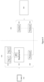
- Figure 2 illustrates an example embodiment of an apparatus 200.
- the apparatus 200 in this exemplary embodiment is a computing unit that may be comprised in or connected to another apparatus such as an automation device.
- the units illustrated in Figure 2 are logical units illustrating the functionalities of the apparatus 200 and the implementation of the functionalities may vary in different embodiments.
- the apparatus 200 comprises a processor 210.
- the processor 210 interprets computer program instructions and processes data.
- the processor 210 may comprise one or more programmable processors.
- the processor 210 may comprise programmable hardware with embedded firmware and may, alternatively or additionally, comprise one or more application specific integrated circuits, ASICs.
- the processor 210 is coupled to a memory 220.
- the processor is configured to read and write data to and from the memory 220.
- the memory 220 may comprise one or more memory units.
- the memory units may be volatile or non-volatile. It is to be noted that in some example embodiments there may be one or more units of non-volatile memory and one or more units of volatile memory or, alternatively, one or more units of non-volatile memory, or, alternatively, one or more units of volatile memory.
- Volatile memory may be for example RAM, DRAM or SDRAM.
- Non-volatile memory may be for example ROM, PROM, EEPROM, flash memory, optical storage or magnetic storage. In general, memories may be referred to as non-transitory computer readable media.
- the memory 220 further stores computer readable instructions that are execute by the processor 210.
- non-volatile memory stores the computer readable instructions and the processor 210 executes the instructions using volatile memory for temporary storage of data and/or instructions.
- the memory may also save data such as values.
- the computer readable instructions may have been pre-stored to the memory 220 or, alternatively or additionally, they may be received, by the apparatus, via electromagnetic carrier signal and/or may be copied from a physical entity such as computer program product. Execution of the computer readable instructions causes the apparatus 200 to perform functionality described above.
- a memory or computer-readable media may be any non-transitory media or means that can contain, store, communicate, propagate or transport the instructions for use by or in connection with an instruction execution system, apparatus, or device, such as a computer.
- the apparatus 200 further comprises, or is connected to, an input unit 230.
- the input unit 230 comprises one or more interfaces for receiving a user input.
- the one or more interfaces may comprise for example one or more motion and/or orientation sensors, one or more cameras, one or more accelerometers, one or more microphones, one or more buttons and one or more touch detection units.
- the input unit 230 may comprise an interface to which external devices may connect to.
- the apparatus 200 also comprises an output unit 240.
- the output unit comprises or is connected to one or more displays capable of rendering visual content such as a light emitting diode, LED, display or a liquid crystal display, LCD.
- the output unit 240 may further comprise one or more audio outputs.
- the one or more audio outputs may be for example loudspeakers or a set of headphones.
- the apparatus 200 may further comprise a connectivity unit 250.
- the connectivity unit 250 enables wired and/or wireless connectivity to external networks such as 5G, Bluetooth or Wi-Fi.
- the connectivity unit 250 may comprise one or more antennas and one or more receivers that may be integrated to the apparatus 200 or the apparatus 200 may be connected to.
- the connectivity unit 250 may comprise an integrated circuit or a set of integrated circuits that provide the wireless communication capability for the apparatus 200.
- the wireless connectivity may be a hardwired application specific integrated circuit, ASIC.
- the apparatus 200 may further comprise a power regulator 260.
- the power regulator may be connected to an electrical supply 262 that may be located outside the apparatus 200 or alternatively, is comprised in the apparatus 200.
- the electrical supply provides power to the power regulator 260 which then adjusts the frequency and voltage and then supplies the power to a motor 264.
- the motor may be located outside the apparatus 200 or it may be comprised in the apparatus 200.
- the apparatus 200 may further comprise various component not illustrated in the Figure 2 .
- the various components may be hardware component and/or software components or a combination thereof.
- An automation device may be a device that is to be used in an industrial environment.
- the automation device may be one device, or it may comprise a plurality of devices that are connected and/or configured to function together and may therefore be considered as one automation device.
- An example of such an automation device is for example a heating, ventilation, and air-conditioning, HVAC, device.
- the automation device may function independent of user input or, alternatively or additionally, a user may guide the functioning of the automation device, at least partly, by providing user input that may be any suitable user input such as press of a button, touch input, gesture input, voice command and so on.
- the automation device that may be used in an industrial environment may comprise a great amount of settings that determine how the automation device functions.
- Configuration may comprise providing correct settings to the automation device by for example providing desired parameter values to one or more parameters comprised in the settings, commissioning the automation device and/or maintaining the automation device.
- the settings of an automation device may be configured using an apparatus such as the apparatus 200 for example.
- the apparatus 200 may be comprised in the automation device or be connected to it.
- the apparatus 200 may further be configured to connect to another apparatus such as the apparatus 100.
- the connection may be for example wireless connection such as Bluetooth or Wi-Fi connection, or it may be a wired connection.
- This may allow a user of the apparatus 100 to control the automation device through the connection between apparatus 100 and apparatus 200.
- This may be beneficial as the apparatus 100 may then comprise an application for example that helps the user to select correct values for each parameter.
- the user may select from a drop-down menu a type of motor that is comprised in the automation device and the application then instructs, using the connection, the apparatus 200 to configure correct parameters for that motor type automatically.
- the user interface may become application specific and not necessarily helpful in optimally guiding a user to commission or maintain the automation device.
- Figure 3 illustrates an exemplary embodiment of a system that provides workflow guidance to a user commissioning or maintaining an automation device.
- a tool for designing a workflow a design tool 310
- the design tool 310 may be a computer-program product that may be stored to a non-transitory medium or it may be obtainable by downloading or the design tool may be executed by a server to which a connection may be established using the Internet for example.
- the design tool may be executed by a computing device such as a laptop or a tablet computer.
- the design tool comprises guidance elements 315.
- a guidance element may be understood as an element that may be visually rendered and that comprises computer instructions or instructions that can be translated into computer instructions by an application, which, when executed by a computing device, cause the computing device to perform a function.
- a guidance element 315 may comprise for example a logical operator, a state machine or a command or query to for example read and/or change a parameter value, check status or a control command and so on.
- a guidance element 315 may comprise for example a logical operator, a state machine or a command or query to for example read and/or change a parameter value, check status or a control command and so on.
- a user may combine various guidance elements. The combining may take place for example by dragging and dropping, by selecting from a list or by using any other suitable means for providing user input.
- the user may also add to the workflow other elements such as images, text and/or state machines not comprised in any guidance element.
- the user may create a workflow 320 that helps others to configure the automation device when for example commissioning or maintaining the automation device.
- the guidance elements 315 may be combined to describe a workflow that comprises a start, a decision point such as "if pump type is A, then set parameter value to X" and/or "if a value is yes, then do B", a stop point and so on.
- the workflow 320 may be visual thereby helping the user to review the designed process and make edits as needed.
- the design tool 310 therefore may enable a user to quickly create various workflows for various targets such as various automation devices used for various purposes in various industrial environments.
- the workflow may further be configured to verify if at least some of the settings of the automation device are correct and to provide output indicating incorrect settings, if any, identified.
- the workflow 320 may be saved as a file comprising the selected guidance elements 315.
- the guidance elements 315 comprised in the workflow may be linked to each other in a certain order.
- the file may be a descriptor file.
- the file may then be saved onto the computing device that was used to execute the design tool 310 and/or the file may be transmitted to another device such as a mobile device 330 and/or the file may be uploaded to a cloud from which it may be downloaded by, for example, the mobile device 330.
- the file may be such that an application may be configured to translate the file into a workflow by translating the guidance elements such that the automation device may be configured as was planned by the user who designed the workflow.
- the application may be called as deployment application and it may be executed by the mobile device 330 that may be or may comprise the apparatus 100.
- the automation device on the other hand may be or may comprise the apparatus 200.
- the deployment application may be configured to connect to the automation device using the connecting unit of the mobile device 330.
- the deployment application may further be configured to determine the type of automation device it is connected to and to which the file is targeted. This enables the deployment application to determine which communication protocol to use for example as it may be different for different automation devices.
- the deployment application may be configured, in some exemplary embodiments, to verify that the user is authorized to execute the workflow. This may be beneficial to ensure that an unauthorized user does not cause harm to the automation device for example by not understanding the consequences of various parameter values.
- the workflow defined by the guidance elements 315 comprised in the file may involve user interaction such as asking a user to provide user input in terms of accepting certain parameter values and so on so it may be beneficial to ensure that only authorized user may provide the user input.
- the deployment application may determine the type of automation device, the parameters and communication protocols used for example by accessing information regarding parameters and communication protocols used in a certain automation device stored in a memory.
- the memory may be that of the mobile device 300, of the automation device or the memory of a back-end such as a cloud.
- the deployment application may further access, in a similar manner, information regarding how the various parameters map to the guidance elements 315 comprised in the file. This enables the deployment application to translate the designed workflow to be compatible with the automation device it is connected to.
- connection between the deployment application and the automation device may be implemented using any suitable connecting means.
- the connection may be for example wireless connection such as Bluetooth or Wi-Fi connection, or it may be a wired connection.
- Figure 4 illustrates an exemplary embodiment of a protocol stack 420 in a mobile device 410 and a protocol stack 450 in an automation device 440.
- a mobile device 410 is a tablet computer.
- the mobile device 410 comprises an application 424 that is a deployment application.
- the deployment application 424 comprises an application programming interface that is configured such that a descriptor file may be translated and executed by the deployment application 424.
- a descriptor file that may have been implemented using a design tool such as the design tool 310 and which comprises a workflow defined by one or more guidance elements, may be obtained from a remote location 422 that may comprise multiple different descriptor files.
- the remote location may be for example a server or a service that is could-based.
- the execution may involve one or more functions that require a connection to the automation device 440.
- the connection may be established using resources of a connectivity unit of the mobile device 410 and a connectivity unit of the automation device 440.
- the connection may be wireless or a wired connection.
- the connection is established according to the communication protocols 430 and 452.
- the communication protocols 430 and 452 define a set of rules that define how the connection between the apparatus 410 and the automation device 440 is to be established.
- the communication protocol 452 there is in the protocol stack 450 a control 452 layer that may be configured to execute functions related to the automation device 440 that are defined in the descriptor file.
- a benefit that may be achieved by the descriptor files is that once the deployment application 424 has been installed to the mobile device 410, no other software needs to be installed.
- the deployment application may be configured to be compatible with various types of automation devices, obtaining a descriptor file that defines the desired workflow for a target automation device 440 and executing the descriptor file using the deployment application may be sufficient if the target automation device is included in the various types of automation devices the deployment application is configured to be compatible with. This enables a user to use the mobile device 410 at various locations and with different automation devices.
- the descriptor file may, when executed, define correct configuration according to the workflow described in the descriptor file, to the automation device automatically without user input.
- the descriptor file when executed by the deployment application, may provide output that invites the user to provide user input.
- the provided user input may then be used as a basis for configuring one or more settings of the automation device.
- Settings may be understood to comprise one or more parameter to which a parameter value is to be provided and/or selected.
- the workflow comprised in the descriptor file may be used to commission and/or maintain an automation device and/or the workflow may guide a user to commission and/or maintain an automation device.
- a pump is to be integrated to an automation system comprising an automation device comprising an apparatus such as the apparatus 200.
- the automation system is the automation device.
- the vendor of the pump may provide a design tool 510 that comprises various workflow elements that may be combined to form a workflow.
- the workflow may then be saved as a descriptor file that may be uploaded to a cloud-based service 520 from which a mobile device 530 may obtain the descriptor file.
- a user that is familiar with how the pump is to be integrated to the automation system may now use the design tool 510 to design a workflow for commissioning the pump as part of the process to integrate the pump to the automation device.
- the user may need to be authenticate such that it is ensured that the user is authorized to use and/or create a descriptor file using the deployment tool.
- the user may then use the design tool 510 to combine various guidance elements to create the workflow.
- the user may do the combining by providing user input such as mouse clicks, dragging and dropping, touch input, key presses and so on.
- the use defines the start of the workflow by selecting the guidance element 512 that is a start command.
- the user then connects the guidance element 512 to the guidance element 514 that is a selector defining that if the pump type is X then proceed to guidance element 516, otherwise proceed to guidance element 5110.
- Guidance element 516 defines that a parameter value for parameter 1 is to be set to 5.69 and the guidance element 5110 defines that the parameter value for the parameter 1 is to be set to 2.34.
- the guidance element 516 and the guidance element 5110 are both then connected to the guidance element 518.
- the guidance element 518 defines the end of the workflow.
- the workflow may be, in some exemplary embodiments, verified by the design tool 510.
- the design tool may be configured to verify that the workflow is safe for example by verifying that the parameter settings are defined to be in a safe range, the order of the guidance elements is sensible and/or safe and so on.
- the user may visually view, using the design tool 510, the workflow he has designed.
- the design tool 510 may have the benefit of enabling the user to quickly create a workflow that may help another user to commission and/or maintain an automation device. This way, the user creating the workflow and the other user do not have to even know each other and/or be in the same location.
- a descriptor file comprising the workflow may be uploaded to a cloud-based service 520 from which it may be downloaded to a deployment application that is installed in the mobile apparatus 530.
- the could-based service 520 may be configured to provide a notification to the mobile apparatus 530 once a descriptor file that is of interest to the user of the mobile apparatus 530 has become available on the cloud-based service 520.
Description
- The present application relates to guiding a workflow relating to commissioning and maintenance of an apparatus in an industrial environment.
- An apparatus that may be used in an industrial environment may have various settings that are to be configured for the apparatus to function properly. The settings may need to be configured differently in various environments and the settings may include multiple parameters and parameter values. To ensure that the settings are configured properly, providing guidance may be beneficial.
-
EP2837979 A1 discloses a manual for a frequency converter and a method, apparatus and a computer program product for configuring a frequency converter. The manual comprises a data storage storing operational configuration information of the frequency converter; wherein the configuration information is encoded to the data storage to be wirelessly readable from the data storage. The configuration information is obtained from the manual by wireless reading means, and installed to the frequency converter by transmitting the obtained configuration information over a wireless connection. -
DE102017108539 A1 discloses a method for monitoring a system of automation technology, wherein in the system a plurality of field devices are involved, the field devices generate data, which in particular to measurement data, control data, calibration/parameterization, diagnostic, history and/or status data and wherein the field devices are in communication with each other and with at least one higher-level unit by means of a first communication network. -
EP3065010 A1 discloses a field device commissioning system includes a commissioning tool configured to communicate with a repository and an input-output (IO) device, the IO device is configured to communicate with a field device. The commissioning tool includes a first processor configured to retrieve engineering data for the IO device or the field device from the repository, retrieve a first configuration parameter value for the IO device or the field device from the IO device, determine a second configuration parameter value for the IO device or the field device from the retrieved engineering data, the second configuration parameter corresponds to the first configuration parameter, determine if the first configuration parameter value is the same as the second configuration parameter value; and generate alert on a user interface with when the first configuration parameter value is not the same as the second configuration parameter value, wherein the IO device comprises a second processor. -
US20090044185 discloses embodiments of a workflow-based user interface for defining and managing functions implemented on mobile devices are described. A method under an embodiment utilizes a workflow-based mobile device management user interface. The method utilizes a pluggable workflow framework to achieve mobile device management externalization. The mobile device management platform is required to implement a set of basic action blocks that are used as primitives for further management policy composition. The method provides a development environment integrated with a mobile device management platform that allows assembling management (monitoring) primitives into meaningful management policies without changes to a core management platform infrastructure. The method claims addition of new primitives deployed as add-on products to enable new and advanced management policies, best integration practices with a carrier operational support system. - Various aspects of examples of the invention are set out in the claims. The scope of protection is set out by the independent claims. Dependent claims define further embodiments included in the scope of protection.
-
-
Figures 1 and2 illustrate exemplary embodiments of an apparatus; -
Figure 3 illustrates an exemplary embodiment of creating a workflow; -
Figure 4 illustrates an exemplary embodiment of protocol stacks; -
Figure 5 illustrates an exemplary embodiment of creating an obtaining a workflow. - The following embodiments are exemplifying. Although the specification may refer to "an", "one", or "some" embodiment(s) in several locations of the text, this does not necessarily mean that each reference is made to the same embodiment(s), or that a particular feature only applies to a single embodiment. Single features of different embodiments may also be combined to provide other embodiments.
-
Figure 1 illustrates an exemplary embodiment of anapparatus 100 which may be a mobile device such as a mobile phone, a tablet computer or a laptop. Theapparatus 100 may also be an apparatus comprised in a device such as an automation device used in an industrial environment. The units illustrated inFigure 1 are logical units illustrating the functionalities of theapparatus 100 and the implementation of the functionalities may vary in different embodiments. - The
apparatus 100 comprises aprocessor 110. Theprocessor 110 interprets computer program instructions and processes data. Theprocessor 110 may comprise one or more programmable processors. Theprocessor 110 may comprise programmable hardware with embedded firmware and may, alternatively or additionally, comprise one or more application specific integrated circuits, ASICs. - The
processor 110 is coupled to amemory 120. The processor is configured to read and write data to and from thememory 120. Thememory 120 may comprise one or more memory units. The memory units may be volatile or non-volatile. It is to be noted that in some example embodiments there may be one or more units of non-volatile memory and one or more units of volatile memory or, alternatively, one or more units of non-volatile memory, or, alternatively, one or more units of volatile memory. Volatile memory may be for example RAM, DRAM or SDRAM. Non-volatile memory may be for example ROM, PROM, EEPROM, flash memory, optical storage or magnetic storage. In general, memories may be referred to as non-transitory computer readable media. Thememory 120 further stores computer readable instructions that are execute by theprocessor 110. For example, non-volatile memory stores the computer readable instructions and theprocessor 110 executes the instructions using volatile memory for temporary storage of data and/or instructions. The memory may also save data such as values. - The computer readable instructions may have been pre-stored to the
memory 120 or, alternatively or additionally, they may be received, by the apparatus, via electromagnetic carrier signal and/or may be copied from a physical entity such as computer program product. Execution of the computer readable instructions causes theapparatus 100 to perform various functionalities such as those described in example embodiments of this document. - In the context of this document, a memory or computer-readable media may be any non-transitory media or means that can contain, store, communicate, propagate or transport the instructions for use by or in connection with an instruction execution system, apparatus, or device, such as a computer.
- The
apparatus 100 further comprises, or is connected to, aninput unit 130. Theinput unit 130 comprises one or more interfaces for receiving input such as user input. The one or more interfaces may comprise for example one or more motion and/or orientation sensors, one or more cameras, one or more accelerometers, one or more microphones, one or more buttons and one or more touch detection units. Further, theinput unit 130 may comprise an interface to which external devices may connect to. - The
apparatus 100 also comprises anoutput unit 140. The output unit comprises or is connected to one or more displays capable of rendering visual content such as a light emitting diode, LED, display, a liquid crystal display, LCD and a liquid crystal on silicon, LCoS, display. Theoutput unit 240 may further comprises one or more audio outputs. The one or more audio outputs may be for example loudspeakers or a set of headphones. - The
apparatus 100 may further comprise aconnectivity unit 150. Theconnectivity unit 150 enables wired and/or wireless connectivity to external networks such as Bluetooth, Wi-Fi, Ethernet, 4G or 5G. Theconnectivity unit 150 may comprise one or more antennas and one or more receivers that may be integrated to theapparatus 100 or theapparatus 100 may be connected to. Theconnectivity unit 150 may comprise an integrated circuit or a set of integrated circuits that provide the wireless communication capability for theapparatus 100. Alternatively, the wireless connectivity may be a hardwired application specific integrated circuit, ASIC. - It is to be noted that the
apparatus 100 may further comprise various components not illustrated in theFigure 1 . The various components may be hardware component and/or software components or a combination thereof. -
Figure 2 illustrates an example embodiment of anapparatus 200. Theapparatus 200 in this exemplary embodiment is a computing unit that may be comprised in or connected to another apparatus such as an automation device. The units illustrated inFigure 2 are logical units illustrating the functionalities of theapparatus 200 and the implementation of the functionalities may vary in different embodiments. - The
apparatus 200 comprises aprocessor 210. Theprocessor 210 interprets computer program instructions and processes data. Theprocessor 210 may comprise one or more programmable processors. Theprocessor 210 may comprise programmable hardware with embedded firmware and may, alternatively or additionally, comprise one or more application specific integrated circuits, ASICs. - The
processor 210 is coupled to amemory 220. The processor is configured to read and write data to and from thememory 220. Thememory 220 may comprise one or more memory units. The memory units may be volatile or non-volatile. It is to be noted that in some example embodiments there may be one or more units of non-volatile memory and one or more units of volatile memory or, alternatively, one or more units of non-volatile memory, or, alternatively, one or more units of volatile memory. Volatile memory may be for example RAM, DRAM or SDRAM. Non-volatile memory may be for example ROM, PROM, EEPROM, flash memory, optical storage or magnetic storage. In general, memories may be referred to as non-transitory computer readable media. Thememory 220 further stores computer readable instructions that are execute by theprocessor 210. For example, non-volatile memory stores the computer readable instructions and theprocessor 210 executes the instructions using volatile memory for temporary storage of data and/or instructions. The memory may also save data such as values. - The computer readable instructions may have been pre-stored to the
memory 220 or, alternatively or additionally, they may be received, by the apparatus, via electromagnetic carrier signal and/or may be copied from a physical entity such as computer program product. Execution of the computer readable instructions causes theapparatus 200 to perform functionality described above. - In the context of this document, a memory or computer-readable media may be any non-transitory media or means that can contain, store, communicate, propagate or transport the instructions for use by or in connection with an instruction execution system, apparatus, or device, such as a computer.
- The
apparatus 200 further comprises, or is connected to, aninput unit 230. Theinput unit 230 comprises one or more interfaces for receiving a user input. The one or more interfaces may comprise for example one or more motion and/or orientation sensors, one or more cameras, one or more accelerometers, one or more microphones, one or more buttons and one or more touch detection units. Further, theinput unit 230 may comprise an interface to which external devices may connect to. - The
apparatus 200 also comprises anoutput unit 240. The output unit comprises or is connected to one or more displays capable of rendering visual content such as a light emitting diode, LED, display or a liquid crystal display, LCD. Theoutput unit 240 may further comprise one or more audio outputs. The one or more audio outputs may be for example loudspeakers or a set of headphones. - The
apparatus 200 may further comprise aconnectivity unit 250. Theconnectivity unit 250 enables wired and/or wireless connectivity to external networks such as 5G, Bluetooth or Wi-Fi. Theconnectivity unit 250 may comprise one or more antennas and one or more receivers that may be integrated to theapparatus 200 or theapparatus 200 may be connected to. Theconnectivity unit 250 may comprise an integrated circuit or a set of integrated circuits that provide the wireless communication capability for theapparatus 200. Alternatively, the wireless connectivity may be a hardwired application specific integrated circuit, ASIC. - In some exemplary embodiments, the
apparatus 200 may further comprise apower regulator 260. The power regulator may be connected to anelectrical supply 262 that may be located outside theapparatus 200 or alternatively, is comprised in theapparatus 200. The electrical supply provides power to thepower regulator 260 which then adjusts the frequency and voltage and then supplies the power to amotor 264. The motor may be located outside theapparatus 200 or it may be comprised in theapparatus 200. - It is to be noted that the
apparatus 200 may further comprise various component not illustrated in theFigure 2 . The various components may be hardware component and/or software components or a combination thereof. - An automation device may be a device that is to be used in an industrial environment. The automation device may be one device, or it may comprise a plurality of devices that are connected and/or configured to function together and may therefore be considered as one automation device. An example of such an automation device is for example a heating, ventilation, and air-conditioning, HVAC, device. The automation device may function independent of user input or, alternatively or additionally, a user may guide the functioning of the automation device, at least partly, by providing user input that may be any suitable user input such as press of a button, touch input, gesture input, voice command and so on. The automation device that may be used in an industrial environment may comprise a great amount of settings that determine how the automation device functions. Further, each industrial environment may be different thereby requiring the settings to be customised for that environment in order for the automation device to function properly. Yet, it may not be clear to a user operating the device how the settings should be configured for the automation device to function properly. In such situations it may be beneficial to provide guidance that helps the user to configure the automation device. Configuration may comprise providing correct settings to the automation device by for example providing desired parameter values to one or more parameters comprised in the settings, commissioning the automation device and/or maintaining the automation device.
- The settings of an automation device may be configured using an apparatus such as the
apparatus 200 for example. Theapparatus 200 may be comprised in the automation device or be connected to it. Theapparatus 200 may further be configured to connect to another apparatus such as theapparatus 100. The connection may be for example wireless connection such as Bluetooth or Wi-Fi connection, or it may be a wired connection. This may allow a user of theapparatus 100 to control the automation device through the connection betweenapparatus 100 andapparatus 200. This may be beneficial as theapparatus 100 may then comprise an application for example that helps the user to select correct values for each parameter. For example, the user may select from a drop-down menu a type of motor that is comprised in the automation device and the application then instructs, using the connection, theapparatus 200 to configure correct parameters for that motor type automatically. Yet, as the level of abstraction is raised, the user interface may become application specific and not necessarily helpful in optimally guiding a user to commission or maintain the automation device. -
Figure 3 illustrates an exemplary embodiment of a system that provides workflow guidance to a user commissioning or maintaining an automation device. A tool for designing a workflow, adesign tool 310, may be provided. Thedesign tool 310 may be a computer-program product that may be stored to a non-transitory medium or it may be obtainable by downloading or the design tool may be executed by a server to which a connection may be established using the Internet for example. The design tool may be executed by a computing device such as a laptop or a tablet computer. The design tool comprisesguidance elements 315. A guidance element may be understood as an element that may be visually rendered and that comprises computer instructions or instructions that can be translated into computer instructions by an application, which, when executed by a computing device, cause the computing device to perform a function. The function to be performed may be indicated in the visual rendering of theguidance element 315. Aguidance element 315 may comprise for example a logical operator, a state machine or a command or query to for example read and/or change a parameter value, check status or a control command and so on. Using the design tool 310 a user may combine various guidance elements. The combining may take place for example by dragging and dropping, by selecting from a list or by using any other suitable means for providing user input. The user may also add to the workflow other elements such as images, text and/or state machines not comprised in any guidance element. - If one user is familiar with an automation device and knows how it may be best configured to one or more environments, he may utilize the
design tool 310 to convey his knowledge to others as well. By combining theguidance elements 315, the user may create aworkflow 320 that helps others to configure the automation device when for example commissioning or maintaining the automation device. For example, theguidance elements 315 may be combined to describe a workflow that comprises a start, a decision point such as "if pump type is A, then set parameter value to X" and/or "if a value is yes, then do B", a stop point and so on. Theworkflow 320 may be visual thereby helping the user to review the designed process and make edits as needed. Thedesign tool 310 therefore may enable a user to quickly create various workflows for various targets such as various automation devices used for various purposes in various industrial environments. In some exemplary embodiments, the workflow may further be configured to verify if at least some of the settings of the automation device are correct and to provide output indicating incorrect settings, if any, identified. - Once the
workflow 320 is ready it may be saved as a file comprising the selectedguidance elements 315. Theguidance elements 315 comprised in the workflow may be linked to each other in a certain order. The file may be a descriptor file. The file may then be saved onto the computing device that was used to execute thedesign tool 310 and/or the file may be transmitted to another device such as amobile device 330 and/or the file may be uploaded to a cloud from which it may be downloaded by, for example, themobile device 330. The file may be such that an application may be configured to translate the file into a workflow by translating the guidance elements such that the automation device may be configured as was planned by the user who designed the workflow. The application may be called as deployment application and it may be executed by themobile device 330 that may be or may comprise theapparatus 100. The automation device on the other hand may be or may comprise theapparatus 200. - The deployment application may be configured to connect to the automation device using the connecting unit of the
mobile device 330. The deployment application may further be configured to determine the type of automation device it is connected to and to which the file is targeted. This enables the deployment application to determine which communication protocol to use for example as it may be different for different automation devices. Further, the deployment application may be configured, in some exemplary embodiments, to verify that the user is authorized to execute the workflow. This may be beneficial to ensure that an unauthorized user does not cause harm to the automation device for example by not understanding the consequences of various parameter values. The workflow defined by theguidance elements 315 comprised in the file may involve user interaction such as asking a user to provide user input in terms of accepting certain parameter values and so on so it may be beneficial to ensure that only authorized user may provide the user input. - As mentioned, different automation devices may use different parameters and/or different communication protocols and so on. The deployment application may determine the type of automation device, the parameters and communication protocols used for example by accessing information regarding parameters and communication protocols used in a certain automation device stored in a memory. The memory may be that of the mobile device 300, of the automation device or the memory of a back-end such as a cloud. The deployment application may further access, in a similar manner, information regarding how the various parameters map to the
guidance elements 315 comprised in the file. This enables the deployment application to translate the designed workflow to be compatible with the automation device it is connected to. - The connection between the deployment application and the automation device may be implemented using any suitable connecting means. The connection may be for example wireless connection such as Bluetooth or Wi-Fi connection, or it may be a wired connection.
-
Figure 4 illustrates an exemplary embodiment of aprotocol stack 420 in amobile device 410 and aprotocol stack 450 in anautomation device 440. In this exemplary embodiment, amobile device 410 is a tablet computer. Themobile device 410 comprises anapplication 424 that is a deployment application. Thedeployment application 424 comprises an application programming interface that is configured such that a descriptor file may be translated and executed by thedeployment application 424. A descriptor file, that may have been implemented using a design tool such as thedesign tool 310 and which comprises a workflow defined by one or more guidance elements, may be obtained from aremote location 422 that may comprise multiple different descriptor files. The remote location may be for example a server or a service that is could-based. Once a descriptor file has been obtained and is executed by thedeployment application 424, the execution may involve one or more functions that require a connection to theautomation device 440. The connection may be established using resources of a connectivity unit of themobile device 410 and a connectivity unit of theautomation device 440. The connection may be wireless or a wired connection. The connection is established according to thecommunication protocols communication protocols apparatus 410 and theautomation device 440 is to be established. After thecommunication protocol 452, there is in the protocol stack 450 acontrol 452 layer that may be configured to execute functions related to theautomation device 440 that are defined in the descriptor file. - A benefit that may be achieved by the descriptor files is that once the
deployment application 424 has been installed to themobile device 410, no other software needs to be installed. As the deployment application may be configured to be compatible with various types of automation devices, obtaining a descriptor file that defines the desired workflow for atarget automation device 440 and executing the descriptor file using the deployment application may be sufficient if the target automation device is included in the various types of automation devices the deployment application is configured to be compatible with. This enables a user to use themobile device 410 at various locations and with different automation devices. The descriptor file may, when executed, define correct configuration according to the workflow described in the descriptor file, to the automation device automatically without user input. Alternatively, the descriptor file, when executed by the deployment application, may provide output that invites the user to provide user input. The provided user input may then be used as a basis for configuring one or more settings of the automation device. Settings may be understood to comprise one or more parameter to which a parameter value is to be provided and/or selected. For example, the workflow comprised in the descriptor file may be used to commission and/or maintain an automation device and/or the workflow may guide a user to commission and/or maintain an automation device. - In an exemplary embodiment illustrated in
Figure 5 , a pump is to be integrated to an automation system comprising an automation device comprising an apparatus such as theapparatus 200. In some exemplary embodiments, the automation system is the automation device. The vendor of the pump may provide adesign tool 510 that comprises various workflow elements that may be combined to form a workflow. The workflow may then be saved as a descriptor file that may be uploaded to a cloud-basedservice 520 from which amobile device 530 may obtain the descriptor file. - A user that is familiar with how the pump is to be integrated to the automation system may now use the
design tool 510 to design a workflow for commissioning the pump as part of the process to integrate the pump to the automation device. Optionally, the user may need to be authenticate such that it is ensured that the user is authorized to use and/or create a descriptor file using the deployment tool. - The user may then use the
design tool 510 to combine various guidance elements to create the workflow. The user may do the combining by providing user input such as mouse clicks, dragging and dropping, touch input, key presses and so on. In this exemplary embodiment, the use defines the start of the workflow by selecting theguidance element 512 that is a start command. The user then connects theguidance element 512 to theguidance element 514 that is a selector defining that if the pump type is X then proceed toguidance element 516, otherwise proceed toguidance element 5110.Guidance element 516 defines that a parameter value forparameter 1 is to be set to 5.69 and theguidance element 5110 defines that the parameter value for theparameter 1 is to be set to 2.34. Theguidance element 516 and theguidance element 5110 are both then connected to theguidance element 518. Theguidance element 518 defines the end of the workflow. - Once the user has defined the workflow, the workflow may be, in some exemplary embodiments, verified by the
design tool 510. The design tool may be configured to verify that the workflow is safe for example by verifying that the parameter settings are defined to be in a safe range, the order of the guidance elements is sensible and/or safe and so on. Further, in some exemplary embodiments, the user may visually view, using thedesign tool 510, the workflow he has designed. Thedesign tool 510 may have the benefit of enabling the user to quickly create a workflow that may help another user to commission and/or maintain an automation device. This way, the user creating the workflow and the other user do not have to even know each other and/or be in the same location. Once the workflow has been designed, a descriptor file comprising the workflow may be uploaded to a cloud-basedservice 520 from which it may be downloaded to a deployment application that is installed in themobile apparatus 530. - In some exemplary embodiments, the could-based
service 520 may be configured to provide a notification to themobile apparatus 530 once a descriptor file that is of interest to the user of themobile apparatus 530 has become available on the cloud-basedservice 520. - Even though the invention has been described above with reference to exemplary embodiments according to the accompanying drawings, it is clear that the invention is not restricted thereto but can be modified in several ways within the scope of the appended claims. Therefore, all words and expressions should be interpreted broadly, and they are intended to illustrate, not to restrict, the embodiment. It will be obvious to a person skilled in the art that, as technology advances, the inventive concept can be implemented in various ways. Further, it is clear to a person skilled in the art that the described exemplary embodiments may, but are not required to, be combined with other exemplary embodiments in various ways. The scope of protection sought for various embodiments of the invention is set out by the independent claims. If any exemplary embodiments and features described in this specification should not fall under the scope of the independent claims, those are to be interpreted as examples useful for understanding various embodiments of the invention.
Claims (12)
- A computer-implemented method comprising:obtaining, by a mobile device comprising a deployment application, a file comprising a plurality of guidance elements (315) that describe a workflow (320) for configuring an apparatus (200) that is an automation device that is used in an industrial environment, wherein the guidance elements (315) are elements that comprise instructions that can be translated into computer instructions by the deployment application, and wherein the plurality of guidance elements are combined to create the workflow (320);connecting to the apparatus (200) and determining, by the deployment application, a type of the apparatus (200) and based on the type of the apparatus (200), determine a communication protocol to use for a connection between the deployment application and the automation device;translating, by the deployment application, the workflow (320) to be compatible with the apparatus (200) by accessing, by the deployment application, information regarding how various parameters map to the plurality of guidance elements (315), wherein the various parameters are comprised in settings of the apparatus (200), that is the automation device, and wherein translation of the workflow comprises translating the guidance elements (315) guidance elements (315) into computer instructions; andcausing the apparatus (200) to be configured by executing the computer instructions.
- A computer-implemented method according to claim 1, wherein the workflow (320) for configuring the apparatus (200) is for commissioning the apparatus (200).
- A computer-implemented method according to claim 1, wherein the workflow (320) for configuring the apparatus (200) is for maintaining the apparatus (200).
- A computer-implemented method according to claim 1, 2 or 3 further comprising determining if one or more settings of the apparatus (200) are correct and if one or more settings are incorrect, providing an output to indicate the one or more incorrect settings.
- A computer-implemented method according to any previous claim, wherein the file is a descriptor file.
- A computer-implemented method according to any previous claim, wherein the file is obtained by downloading it to the deployment application, wherein the deployment application is comprised in a mobile device (330), and the mobile device is connected to the apparatus (200).
- A computer-implemented method according to any previous claim, wherein the connecting to the apparatus (200) is done using a wireless connection.
- A computer-implemented method according to any previous claim, wherein the method further comprises determining a plurality of parameters comprised in the apparatus (200).
- A computer-implemented method according to any previous claim, wherein the guidance elements (315) are linked to each other in a certain order.
- A computer-implemented method according to any previous claim, wherein the workflow (320) comprises a start point, a decision point and a stop point.
- An apparatus comprising means for implementing a method according to any of claims 1 to 10.
- A computer product program which when executed by a computing apparatus causes the apparatus to perform a method according to any of claim 1 to 10
Priority Applications (3)
| Application Number | Priority Date | Filing Date | Title |
|---|---|---|---|
| EP19177984.2A EP3748440B1 (en) | 2019-06-03 | 2019-06-03 | Workflow of an apparatus |
| CN202010483983.4A CN112035223B (en) | 2019-06-03 | 2020-06-01 | Workflow of a device |
| US16/891,384 US11409269B2 (en) | 2019-06-03 | 2020-06-03 | Workflow of an apparatus |
Applications Claiming Priority (1)
| Application Number | Priority Date | Filing Date | Title |
|---|---|---|---|
| EP19177984.2A EP3748440B1 (en) | 2019-06-03 | 2019-06-03 | Workflow of an apparatus |
Publications (3)
| Publication Number | Publication Date |
|---|---|
| EP3748440A1 EP3748440A1 (en) | 2020-12-09 |
| EP3748440C0 EP3748440C0 (en) | 2023-11-08 |
| EP3748440B1 true EP3748440B1 (en) | 2023-11-08 |
Family
ID=67003169
Family Applications (1)
| Application Number | Title | Priority Date | Filing Date |
|---|---|---|---|
| EP19177984.2A Active EP3748440B1 (en) | 2019-06-03 | 2019-06-03 | Workflow of an apparatus |
Country Status (3)
| Country | Link |
|---|---|
| US (1) | US11409269B2 (en) |
| EP (1) | EP3748440B1 (en) |
| CN (1) | CN112035223B (en) |
Citations (1)
| Publication number | Priority date | Publication date | Assignee | Title |
|---|---|---|---|---|
| US20090044185A1 (en) * | 2007-08-08 | 2009-02-12 | Innopath Software, Inc. | Workflow-Based User Interface System for Mobile Devices Management |
Family Cites Families (23)
| Publication number | Priority date | Publication date | Assignee | Title |
|---|---|---|---|---|
| US6708329B1 (en) * | 2000-05-26 | 2004-03-16 | Itt Manufacturing Enterprises, Inc. | Method and apparatus for producing modules compatible with a target system platform from simulation system modules utilized to model target system behavior |
| US7689676B2 (en) * | 2003-03-06 | 2010-03-30 | Microsoft Corporation | Model-based policy application |
| US20060074735A1 (en) * | 2004-10-01 | 2006-04-06 | Microsoft Corporation | Ink-enabled workflow authoring |
| US7233830B1 (en) * | 2005-05-31 | 2007-06-19 | Rockwell Automation Technologies, Inc. | Application and service management for industrial control devices |
| US20080244565A1 (en) * | 2007-03-29 | 2008-10-02 | Microsoft Corporation | Dynamic software installation and configuration |
| US8763006B2 (en) * | 2007-12-28 | 2014-06-24 | International Business Machines Corporation | Dynamic generation of processes in computing environments |
| DE102009043968A1 (en) * | 2009-09-09 | 2014-03-20 | Schneider Electric Automation Gmbh | Petri net-based approaches and tools for development, deployment and operation of orchestration engines embedded in automation devices |
| US9551983B2 (en) * | 2011-11-15 | 2017-01-24 | Rockwell Automation Technologies, Inc. | Activity set management in a Manufacturing Execution System |
| JP6029321B2 (en) * | 2012-05-28 | 2016-11-24 | キヤノン株式会社 | Image forming apparatus, control method therefor, and program |
| US9336288B2 (en) * | 2013-06-03 | 2016-05-10 | Bank Of America Corporation | Workflow controller compatibility |
| EP2837979B1 (en) * | 2013-08-13 | 2021-11-24 | ABB Schweiz AG | A method, apparatus and a computer program product for configuring a frequency converter |
| US20150230044A1 (en) * | 2014-02-12 | 2015-08-13 | Continental Automotive Systems, Inc. | Updating vehicle software using a smartphone |
| US10120663B2 (en) * | 2014-03-28 | 2018-11-06 | Intel Corporation | Inter-architecture compatability module to allow code module of one architecture to use library module of another architecture |
| CN106716274B (en) * | 2014-09-30 | 2021-03-16 | 西门子瑞士有限公司 | Configuring a universal automation system controller |
| US9921569B2 (en) * | 2015-03-06 | 2018-03-20 | Yokogawa Electric Corporation | Field device commissioning system and method |
| CN108431803A (en) * | 2015-09-28 | 2018-08-21 | 皇家飞利浦有限公司 | Recipe is shared and is adapted to |
| US10606565B2 (en) * | 2017-01-31 | 2020-03-31 | Stackery, Inc. | Visual devops systems and methods |
| US10469317B1 (en) * | 2017-03-29 | 2019-11-05 | Juniper Networks, Inc. | Virtualized network function descriptors for virtualized network function configuration |
| US20180285092A1 (en) * | 2017-03-29 | 2018-10-04 | Achutha Narayana Raman | Software update intervention as a service for industrial control systems |
| DE102017108539A1 (en) * | 2017-04-21 | 2018-10-25 | Endress+Hauser Process Solutions Ag | Method and cloud gateway for monitoring a plant of automation technology |
| US10387126B2 (en) * | 2017-06-30 | 2019-08-20 | Microsoft Technology Licensing, Llc | Data marshalling optimization via intermediate representation of workflows |
| US10956413B2 (en) * | 2018-10-31 | 2021-03-23 | Salesforce.Com, Inc. | Action set translation |
| US11706314B2 (en) * | 2018-11-26 | 2023-07-18 | Amazon Technologies, Inc. | Configuration of workflows for coordinated device environments |
-
2019
- 2019-06-03 EP EP19177984.2A patent/EP3748440B1/en active Active
-
2020
- 2020-06-01 CN CN202010483983.4A patent/CN112035223B/en active Active
- 2020-06-03 US US16/891,384 patent/US11409269B2/en active Active
Patent Citations (1)
| Publication number | Priority date | Publication date | Assignee | Title |
|---|---|---|---|---|
| US20090044185A1 (en) * | 2007-08-08 | 2009-02-12 | Innopath Software, Inc. | Workflow-Based User Interface System for Mobile Devices Management |
Also Published As
| Publication number | Publication date |
|---|---|
| CN112035223A (en) | 2020-12-04 |
| EP3748440C0 (en) | 2023-11-08 |
| US20200379446A1 (en) | 2020-12-03 |
| CN112035223B (en) | 2024-03-08 |
| EP3748440A1 (en) | 2020-12-09 |
| US11409269B2 (en) | 2022-08-09 |
Similar Documents
| Publication | Publication Date | Title |
|---|---|---|
| US9535415B2 (en) | Software, systems, and methods for mobile visualization of industrial automation environments | |
| US9892559B2 (en) | Portable terminal device, and portable control device | |
| US10700926B2 (en) | Accessing gateway management console | |
| US10652107B2 (en) | Accessing gateway management console | |
| US11689414B2 (en) | Accessing gateway management console | |
| EP3352033B1 (en) | Maintenance operation support device, maintenance operation support method, and non-transitory computer readable storage medium | |
| KR101047899B1 (en) | User interface automatic generation and industrial facility controlling system using portable terminal | |
| EP3073632B1 (en) | Trace-data recording system, trace-data recording server, trace-data recording method, program, and information storage medium | |
| US9898925B2 (en) | Method for operating a field device | |
| EP2952986B1 (en) | Field device management system | |
| EP2863281B1 (en) | System and method to configure a field device | |
| JP6111980B2 (en) | Industrial equipment management system, industrial equipment management server, industrial equipment management method, program, and information storage medium | |
| US20150018996A1 (en) | Device setting apparatus, recording medium recording device setting program, information transfer system, and information transfer method | |
| JP2015087877A (en) | Industrial equipment production system, industrial equipment production server, industrial equipment production method, program, and information storage medium | |
| EP2813909B1 (en) | On-demand device templates for integrating devices in a processing facility | |
| US20150088436A1 (en) | Customer-specific configuration and parameterisation of level measurement devices during the ordering process | |
| EP3748440B1 (en) | Workflow of an apparatus | |
| JP2006318102A (en) | Field equipment management device and field equipment management method | |
| JP2020017922A (en) | Radio communication system | |
| US20210109980A1 (en) | Website-Lifecycle Management Tool | |
| EP4332705A1 (en) | Industrial automation system topology with point to point representation paths | |
| EP4325795A1 (en) | Background discovery agent orchestration | |
| US20170134500A1 (en) | System and method for creating operating systems to network physical objects or things | |
| KR20110003989A (en) | Graphich user interface service system for embedded computer | |
| KR20180112709A (en) | Monitoring system, device and engineering tool |
Legal Events
| Date | Code | Title | Description |
|---|---|---|---|
| PUAI | Public reference made under article 153(3) epc to a published international application that has entered the european phase |
Free format text: ORIGINAL CODE: 0009012 |
|
| STAA | Information on the status of an ep patent application or granted ep patent |
Free format text: STATUS: THE APPLICATION HAS BEEN PUBLISHED |
|
| AK | Designated contracting states |
Kind code of ref document: A1 Designated state(s): AL AT BE BG CH CY CZ DE DK EE ES FI FR GB GR HR HU IE IS IT LI LT LU LV MC MK MT NL NO PL PT RO RS SE SI SK SM TR |
|
| AX | Request for extension of the european patent |
Extension state: BA ME |
|
| STAA | Information on the status of an ep patent application or granted ep patent |
Free format text: STATUS: REQUEST FOR EXAMINATION WAS MADE |
|
| STAA | Information on the status of an ep patent application or granted ep patent |
Free format text: STATUS: EXAMINATION IS IN PROGRESS |
|
| 17P | Request for examination filed |
Effective date: 20210607 |
|
| RBV | Designated contracting states (corrected) |
Designated state(s): AL AT BE BG CH CY CZ DE DK EE ES FI FR GB GR HR HU IE IS IT LI LT LU LV MC MK MT NL NO PL PT RO RS SE SI SK SM TR |
|
| 17Q | First examination report despatched |
Effective date: 20210705 |
|
| GRAP | Despatch of communication of intention to grant a patent |
Free format text: ORIGINAL CODE: EPIDOSNIGR1 |
|
| STAA | Information on the status of an ep patent application or granted ep patent |
Free format text: STATUS: GRANT OF PATENT IS INTENDED |
|
| INTG | Intention to grant announced |
Effective date: 20230602 |
|
| GRAS | Grant fee paid |
Free format text: ORIGINAL CODE: EPIDOSNIGR3 |
|
| RAP3 | Party data changed (applicant data changed or rights of an application transferred) |
Owner name: ABB SCHWEIZ AG |
|
| GRAA | (expected) grant |
Free format text: ORIGINAL CODE: 0009210 |
|
| STAA | Information on the status of an ep patent application or granted ep patent |
Free format text: STATUS: THE PATENT HAS BEEN GRANTED |
|
| AK | Designated contracting states |
Kind code of ref document: B1 Designated state(s): AL AT BE BG CH CY CZ DE DK EE ES FI FR GB GR HR HU IE IS IT LI LT LU LV MC MK MT NL NO PL PT RO RS SE SI SK SM TR |
|
| REG | Reference to a national code |
Ref country code: GB Ref legal event code: FG4D |
|
| REG | Reference to a national code |
Ref country code: CH Ref legal event code: EP |
|
| REG | Reference to a national code |
Ref country code: DE Ref legal event code: R096 Ref document number: 602019040924 Country of ref document: DE |
|
| REG | Reference to a national code |
Ref country code: IE Ref legal event code: FG4D |
|
| U01 | Request for unitary effect filed |
Effective date: 20231130 |
|
| U07 | Unitary effect registered |
Designated state(s): AT BE BG DE DK EE FI FR IT LT LU LV MT NL PT SE SI Effective date: 20231206 |
|
| PG25 | Lapsed in a contracting state [announced via postgrant information from national office to epo] |
Ref country code: GR Free format text: LAPSE BECAUSE OF FAILURE TO SUBMIT A TRANSLATION OF THE DESCRIPTION OR TO PAY THE FEE WITHIN THE PRESCRIBED TIME-LIMIT Effective date: 20240209 |
|
| PG25 | Lapsed in a contracting state [announced via postgrant information from national office to epo] |
Ref country code: IS Free format text: LAPSE BECAUSE OF FAILURE TO SUBMIT A TRANSLATION OF THE DESCRIPTION OR TO PAY THE FEE WITHIN THE PRESCRIBED TIME-LIMIT Effective date: 20240308 |