EP3748429A1 - Camera module - Google Patents
Camera module Download PDFInfo
- Publication number
- EP3748429A1 EP3748429A1 EP19747671.6A EP19747671A EP3748429A1 EP 3748429 A1 EP3748429 A1 EP 3748429A1 EP 19747671 A EP19747671 A EP 19747671A EP 3748429 A1 EP3748429 A1 EP 3748429A1
- Authority
- EP
- European Patent Office
- Prior art keywords
- mover
- disposed
- lens group
- camera module
- optical
- Prior art date
- Legal status (The legal status is an assumption and is not a legal conclusion. Google has not performed a legal analysis and makes no representation as to the accuracy of the status listed.)
- Pending
Links
Images






Classifications
-
- G—PHYSICS
- G03—PHOTOGRAPHY; CINEMATOGRAPHY; ANALOGOUS TECHNIQUES USING WAVES OTHER THAN OPTICAL WAVES; ELECTROGRAPHY; HOLOGRAPHY
- G03B—APPARATUS OR ARRANGEMENTS FOR TAKING PHOTOGRAPHS OR FOR PROJECTING OR VIEWING THEM; APPARATUS OR ARRANGEMENTS EMPLOYING ANALOGOUS TECHNIQUES USING WAVES OTHER THAN OPTICAL WAVES; ACCESSORIES THEREFOR
- G03B30/00—Camera modules comprising integrated lens units and imaging units, specially adapted for being embedded in other devices, e.g. mobile phones or vehicles
-
- G—PHYSICS
- G02—OPTICS
- G02B—OPTICAL ELEMENTS, SYSTEMS OR APPARATUS
- G02B7/00—Mountings, adjusting means, or light-tight connections, for optical elements
- G02B7/02—Mountings, adjusting means, or light-tight connections, for optical elements for lenses
- G02B7/04—Mountings, adjusting means, or light-tight connections, for optical elements for lenses with mechanism for focusing or varying magnification
- G02B7/09—Mountings, adjusting means, or light-tight connections, for optical elements for lenses with mechanism for focusing or varying magnification adapted for automatic focusing or varying magnification
-
- G—PHYSICS
- G02—OPTICS
- G02B—OPTICAL ELEMENTS, SYSTEMS OR APPARATUS
- G02B13/00—Optical objectives specially designed for the purposes specified below
- G02B13/001—Miniaturised objectives for electronic devices, e.g. portable telephones, webcams, PDAs, small digital cameras
- G02B13/0055—Miniaturised objectives for electronic devices, e.g. portable telephones, webcams, PDAs, small digital cameras employing a special optical element
- G02B13/0065—Miniaturised objectives for electronic devices, e.g. portable telephones, webcams, PDAs, small digital cameras employing a special optical element having a beam-folding prism or mirror
-
- G—PHYSICS
- G02—OPTICS
- G02B—OPTICAL ELEMENTS, SYSTEMS OR APPARATUS
- G02B15/00—Optical objectives with means for varying the magnification
- G02B15/14—Optical objectives with means for varying the magnification by axial movement of one or more lenses or groups of lenses relative to the image plane for continuously varying the equivalent focal length of the objective
- G02B15/143—Optical objectives with means for varying the magnification by axial movement of one or more lenses or groups of lenses relative to the image plane for continuously varying the equivalent focal length of the objective having three groups only
-
- G—PHYSICS
- G02—OPTICS
- G02B—OPTICAL ELEMENTS, SYSTEMS OR APPARATUS
- G02B26/00—Optical devices or arrangements for the control of light using movable or deformable optical elements
- G02B26/08—Optical devices or arrangements for the control of light using movable or deformable optical elements for controlling the direction of light
- G02B26/0875—Optical devices or arrangements for the control of light using movable or deformable optical elements for controlling the direction of light by means of one or more refracting elements
- G02B26/0883—Optical devices or arrangements for the control of light using movable or deformable optical elements for controlling the direction of light by means of one or more refracting elements the refracting element being a prism
-
- G—PHYSICS
- G02—OPTICS
- G02B—OPTICAL ELEMENTS, SYSTEMS OR APPARATUS
- G02B7/00—Mountings, adjusting means, or light-tight connections, for optical elements
- G02B7/02—Mountings, adjusting means, or light-tight connections, for optical elements for lenses
- G02B7/04—Mountings, adjusting means, or light-tight connections, for optical elements for lenses with mechanism for focusing or varying magnification
- G02B7/10—Mountings, adjusting means, or light-tight connections, for optical elements for lenses with mechanism for focusing or varying magnification by relative axial movement of several lenses, e.g. of varifocal objective lens
- G02B7/102—Mountings, adjusting means, or light-tight connections, for optical elements for lenses with mechanism for focusing or varying magnification by relative axial movement of several lenses, e.g. of varifocal objective lens controlled by a microcomputer
-
- G—PHYSICS
- G03—PHOTOGRAPHY; CINEMATOGRAPHY; ANALOGOUS TECHNIQUES USING WAVES OTHER THAN OPTICAL WAVES; ELECTROGRAPHY; HOLOGRAPHY
- G03B—APPARATUS OR ARRANGEMENTS FOR TAKING PHOTOGRAPHS OR FOR PROJECTING OR VIEWING THEM; APPARATUS OR ARRANGEMENTS EMPLOYING ANALOGOUS TECHNIQUES USING WAVES OTHER THAN OPTICAL WAVES; ACCESSORIES THEREFOR
- G03B13/00—Viewfinders; Focusing aids for cameras; Means for focusing for cameras; Autofocus systems for cameras
- G03B13/32—Means for focusing
- G03B13/34—Power focusing
- G03B13/36—Autofocus systems
-
- G—PHYSICS
- G03—PHOTOGRAPHY; CINEMATOGRAPHY; ANALOGOUS TECHNIQUES USING WAVES OTHER THAN OPTICAL WAVES; ELECTROGRAPHY; HOLOGRAPHY
- G03B—APPARATUS OR ARRANGEMENTS FOR TAKING PHOTOGRAPHS OR FOR PROJECTING OR VIEWING THEM; APPARATUS OR ARRANGEMENTS EMPLOYING ANALOGOUS TECHNIQUES USING WAVES OTHER THAN OPTICAL WAVES; ACCESSORIES THEREFOR
- G03B3/00—Focusing arrangements of general interest for cameras, projectors or printers
- G03B3/10—Power-operated focusing
-
- G—PHYSICS
- G03—PHOTOGRAPHY; CINEMATOGRAPHY; ANALOGOUS TECHNIQUES USING WAVES OTHER THAN OPTICAL WAVES; ELECTROGRAPHY; HOLOGRAPHY
- G03B—APPARATUS OR ARRANGEMENTS FOR TAKING PHOTOGRAPHS OR FOR PROJECTING OR VIEWING THEM; APPARATUS OR ARRANGEMENTS EMPLOYING ANALOGOUS TECHNIQUES USING WAVES OTHER THAN OPTICAL WAVES; ACCESSORIES THEREFOR
- G03B5/00—Adjustment of optical system relative to image or object surface other than for focusing
-
- H—ELECTRICITY
- H04—ELECTRIC COMMUNICATION TECHNIQUE
- H04N—PICTORIAL COMMUNICATION, e.g. TELEVISION
- H04N23/00—Cameras or camera modules comprising electronic image sensors; Control thereof
- H04N23/50—Constructional details
- H04N23/54—Mounting of pick-up tubes, electronic image sensors, deviation or focusing coils
-
- H—ELECTRICITY
- H04—ELECTRIC COMMUNICATION TECHNIQUE
- H04N—PICTORIAL COMMUNICATION, e.g. TELEVISION
- H04N23/00—Cameras or camera modules comprising electronic image sensors; Control thereof
- H04N23/50—Constructional details
- H04N23/55—Optical parts specially adapted for electronic image sensors; Mounting thereof
-
- H—ELECTRICITY
- H04—ELECTRIC COMMUNICATION TECHNIQUE
- H04N—PICTORIAL COMMUNICATION, e.g. TELEVISION
- H04N23/00—Cameras or camera modules comprising electronic image sensors; Control thereof
- H04N23/57—Mechanical or electrical details of cameras or camera modules specially adapted for being embedded in other devices
-
- G—PHYSICS
- G03—PHOTOGRAPHY; CINEMATOGRAPHY; ANALOGOUS TECHNIQUES USING WAVES OTHER THAN OPTICAL WAVES; ELECTROGRAPHY; HOLOGRAPHY
- G03B—APPARATUS OR ARRANGEMENTS FOR TAKING PHOTOGRAPHS OR FOR PROJECTING OR VIEWING THEM; APPARATUS OR ARRANGEMENTS EMPLOYING ANALOGOUS TECHNIQUES USING WAVES OTHER THAN OPTICAL WAVES; ACCESSORIES THEREFOR
- G03B17/00—Details of cameras or camera bodies; Accessories therefor
- G03B17/02—Bodies
- G03B17/17—Bodies with reflectors arranged in beam forming the photographic image, e.g. for reducing dimensions of camera
-
- G—PHYSICS
- G03—PHOTOGRAPHY; CINEMATOGRAPHY; ANALOGOUS TECHNIQUES USING WAVES OTHER THAN OPTICAL WAVES; ELECTROGRAPHY; HOLOGRAPHY
- G03B—APPARATUS OR ARRANGEMENTS FOR TAKING PHOTOGRAPHS OR FOR PROJECTING OR VIEWING THEM; APPARATUS OR ARRANGEMENTS EMPLOYING ANALOGOUS TECHNIQUES USING WAVES OTHER THAN OPTICAL WAVES; ACCESSORIES THEREFOR
- G03B2205/00—Adjustment of optical system relative to image or object surface other than for focusing
- G03B2205/0007—Movement of one or more optical elements for control of motion blur
-
- G—PHYSICS
- G03—PHOTOGRAPHY; CINEMATOGRAPHY; ANALOGOUS TECHNIQUES USING WAVES OTHER THAN OPTICAL WAVES; ELECTROGRAPHY; HOLOGRAPHY
- G03B—APPARATUS OR ARRANGEMENTS FOR TAKING PHOTOGRAPHS OR FOR PROJECTING OR VIEWING THEM; APPARATUS OR ARRANGEMENTS EMPLOYING ANALOGOUS TECHNIQUES USING WAVES OTHER THAN OPTICAL WAVES; ACCESSORIES THEREFOR
- G03B2205/00—Adjustment of optical system relative to image or object surface other than for focusing
- G03B2205/0046—Movement of one or more optical elements for zooming
-
- G—PHYSICS
- G03—PHOTOGRAPHY; CINEMATOGRAPHY; ANALOGOUS TECHNIQUES USING WAVES OTHER THAN OPTICAL WAVES; ELECTROGRAPHY; HOLOGRAPHY
- G03B—APPARATUS OR ARRANGEMENTS FOR TAKING PHOTOGRAPHS OR FOR PROJECTING OR VIEWING THEM; APPARATUS OR ARRANGEMENTS EMPLOYING ANALOGOUS TECHNIQUES USING WAVES OTHER THAN OPTICAL WAVES; ACCESSORIES THEREFOR
- G03B2205/00—Adjustment of optical system relative to image or object surface other than for focusing
- G03B2205/0053—Driving means for the movement of one or more optical element
Definitions
- Embodiments relate to a camera module configured to perform auto-focusing and zoom-up functions.
- a camera module may include a lens, an image sensor module, and a lens-moving device for adjusting the distance between the lens and the image sensor module.
- Camera modules may perform an auto-focusing function of adjusting the distance between an image sensor and a lens to control the focal length of the lens.
- camera modules may also perform a zoom-up function, i.e. a function of photographing an object located a long distance away with increased magnification.
- miniature camera modules have a limited size, there is a problem in that it is difficult to construct miniature camera modules such that they perform a zoom-up function of the type implemented in general large-scale cameras.
- Embodiments relate to a camera module configured to perform auto-focusing and zoom-up functions.
- a camera module may include a prism configured to change an optical path and a moving unit disposed opposite the prism.
- the moving unit may include a first lens group disposed adjacent to the prism, a second lens group disposed so as to be spaced apart from the first lens group in an optical-axis direction, a third lens group disposed between the first lens group and the second lens group and configured to move in the optical-axis direction, a guide bar disposed such that the longitudinal direction thereof is oriented in the optical-axis direction and configured to be in sliding contact with the third lens group to guide movement of the third lens group, and a base to which the guide bar is mounted.
- the third lens group may include a mover, which is provided in a plural number and includes at least one lens.
- the mover may include a first mover, disposed adjacent to the first lens group, and a second mover, disposed between the first mover and the second lens group.
- the guide bar may be provided in a plural number so as to surround the first lens group, the second lens group, and the third lens group.
- the mover may include a guide groove in which the guide bar is disposed so as to be in sliding contact therewith.
- the guide groove may include a protruding portion formed to be in contact with the guide bar in order to reduce the contact area with the guide bar.
- the camera module may further include a coupling member coupled to at least one end of the guide bar to fix the position of the guide bar.
- the camera module may further include a driving magnet coupled to the mover and a coil part coupled to the base and disposed opposite the driving magnet.
- the coil part may include a yoke mounted to the base and disposed such that the longitudinal direction thereof is oriented in the optical-axis direction and a moving coil wound on the yoke such that a part thereof is disposed opposite the driving magnet.
- the camera module may further include a sensing magnet coupled to the mover, a position sensor coupled to the base and disposed opposite the sensing magnet, and a second printed circuit board coupled to the base and configured to allow the position sensor to be mounted thereon.
- the sensing magnet may be spaced apart from the driving magnet in the optical-axis direction and in a direction perpendicular to the optical-axis direction
- the position sensor may be spaced apart from the coil part in the optical-axis direction and in a direction perpendicular to the optical-axis direction.
- the base may include a mounting groove in which the guide bar is mounted, and the mounting groove may be formed in the longitudinal direction of the guide bar.
- the camera module may further include a first printed circuit board coupled to the bottom surface of the base.
- the camera module may further include a cover member configured to accommodate the prism and the moving unit.
- the camera module may further include an OIS correction unit, disposed between the prism and the moving unit, and a second photographing unit, spaced apart from the prism and the moving unit.
- a camera module may include a base, a plurality of guide bars coupled to the base, a first mover disposed in the base and including at least one lens disposed therein, and a second mover disposed in the base and including at least one lens disposed therein.
- Each of the first mover and the second mover may include a plurality of guide grooves formed therein to allow the guide bars to be disposed therein, and each of the guide grooves may include a protruding portion formed to be in contact with a respective one of the guide bars.
- the camera module may include a prism configured to change an optical path of external light incident thereon such that the optical path is oriented in a direction perpendicular to the direction in which the lens disposed in the first mover and the lens disposed in the second mover are aligned.
- the guide bars may be disposed so as to surround the first mover and the second mover.
- the camera module may further include a coupling member coupled to at least one end of each of the guide bars to fix the positions of the guide bars.
- the base may include mounting grooves formed therein to allow the guide bars to be disposed therein.
- the camera module may further include a first driving magnet disposed at one side of the first mover, a first coil part coupled to the base and disposed opposite the first driving magnet, a sensing magnet disposed at the opposite side of the mover, and a first position sensor coupled to the base and disposed opposite the sensing magnet.
- the first sensing magnet may be spaced apart from the first driving magnet in a direction perpendicular to the optical-axis direction.
- the camera module may further include a lens disposed between the prism and the first mover or between the prism and the second mover.
- the camera module may further include a lens disposed between the first mover and the second mover.
- a third lens group which is disposed between a first lens group and a second lens group, is composed of two lens groups, and the moving directions and the moving distances of the respective lens groups are independently adjusted by a first mover and a second mover.
- a mover is provided so as to move in an optical-axis direction through sliding contact between a guide bar and the mover, a camera module capable of efficiently performing auto-focusing and zoom-up functions with a simple structure may be realized.
- a third lens group and a second lens group are sequentially disposed behind a first lens group, and the moving directions and the moving distances of the second lens group and the third lens group are independently adjusted by a first mover and a second mover.
- a camera module according to an embodiment is capable of efficiently and accurately performing auto-focusing and zoom-up functions.
- relational terms such as “on/upper part/above” and “under/lower part/below”, are used only to distinguish between one subject or element and another subject or element, without necessarily requiring or involving any physical or logical relationship or sequence between such subjects or elements.
- the optical-axis direction is a direction that is the same as or parallel to the direction in which a first lens group 210 to a third lens group 230 are aligned.
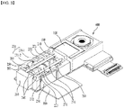
- FIG. 1 is a perspective view illustrating a camera module according to an embodiment.
- FIG. 2 is a cross-sectional view of FIG. 1 when viewed from the side.
- FIG. 3 is a perspective view of FIG. 1 , from which a cover member 400 is removed.
- FIG. 4 is a plan view of FIG. 3 .
- a camera module may include at least one of a first photographing unit or a second photographing unit, and one thereof may be omitted.
- the camera module may include a prism 100, a moving unit 200, a cover member 400, and a first printed circuit board 300.
- a part including the prism 100 and the moving unit 200 may be the first photographing unit.
- the second photographing unit 600 may be disposed so as to be spaced apart from the first photographing unit including the prism 100 and the moving unit 200.
- the first photographing unit 100 and 200 and the second photographing unit 600 may be independently provided to capture an image, and may be driven by one controller (not illustrated).
- the images captured by the first photographing unit 100 and 200 and the second photographing unit 600 may be edited by the controller to be expressed as a single image.
- the image edited by the controller may become a wide-angle image or a zoomed-up image with a high resolution compared with the image captured by one of the first photographing unit 100 and 200 and the second photographing unit 600.
- the camera module of the embodiment may be, for example, a miniature camera module for use in smartphones, tablet PCs, or the like. Therefore, the camera module may function as a so-called dual camera, in which the first photographing unit 100 and 200 and the second photographing unit 600 are separately provided and the images captured thereby are edited to a single image.
- the second photographing unit 600 may be implemented as a general camera device. Thus, the following description will focus on the first photographing unit including the prism 100 and the moving unit 200.
- the cover member 400 may cover the entirety of the camera module to accommodate the first photographing unit, which includes the prism 100 and the moving unit 200, and the components constituting the second photographing unit 600 so as to protect these components.
- the cover member 400 may be bonded to a base 250, which accommodates the prism 100 and the moving unit 200, and may also be bonded to a housing, which accommodates the second photographing unit 600, thereby protecting the components of the camera module.
- the prism 100 may be disposed in front of the moving unit 200 to change an optical path.
- external light may be incident on the prism 100 in the optical-axis direction, i.e. in a direction perpendicular to the direction in which the first lens group 210 to the third lens group 230 are aligned.
- the optical path of the external light incident on the prism 100 may be changed so as to be oriented in the optical-axis direction.
- the external light may sequentially pass through the first lens group 210, the third lens group 230, and the second lens group 220.
- the prism 100 may have a total reflection surface, which is formed so as to be oriented in an oblique direction relative to the optical-axis direction.
- the external light incident on the prism 100 may be totally reflected by the total reflection surface, and the optical path thereof may be changed so as to be oriented in the optical-axis direction.
- the moving unit 200 may be disposed opposite the prism 100 in the optical-axis direction so that the light emitted from the prism 100 passes through the moving unit 200 in the optical-axis direction.
- the moving unit 200 may implement the auto-focusing or zoom-up function of the camera module.
- the camera module may include an optical image stabilization (OIS) correction unit 500, which is disposed between the prism 100 and the moving unit 200.
- OIS optical image stabilization
- the OIS correction unit 500 may prevent or compensate for shaking of the image captured by the camera module due to a user's hand tremor or other disturbances, thereby improving the quality of the image.
- the OIS correction unit 500 be designed so as to have a small volume and to effectively perform the OIS function. Therefore, the OIS correction unit 500 may be implemented as a device including a liquid lens, which is capable of preventing shaking of an image by changing the shape of a liquid provided therein in response to current applied thereto.
- the moving unit 200 may include the first lens group 210, the second lens group 220, the third lens group 230, a guide bar 240, and the base 250.
- the light emitted from the prism 100 may sequentially pass through the first lens group 210, the third lens group 230, and the second lens group 220.
- an image sensor may be disposed behind the second lens group 220.
- the light emitted from the second lens group 220 may be incident on the image sensor, and the image sensor may form an image using the incident light.
- the distance between the first lens group 210, the third lens group 230, and the second lens group 220 may be adjusted in order to implement auto-focusing and zoom-up with respect to an image captured by the camera module.
- auto-focusing and zoom-up may be implemented by moving the third lens group 230 in the optical-axis direction to adjust the distance between the first lens group 210 and the third lens group 230 and the distance between the third lens group 230 and the second lens group 220.
- Each of the first lens group 210, the third lens group 230, and the second lens group 220 may be configured such that one or two or more lenses are aligned in the optical-axis direction to form an optical system and are mounted in a barrel.
- the first lens group 210 may be disposed adjacent to the prism 100, and the light emitted from the prism 100 may enter the first lens group 210.
- the second lens group 220 may be spaced apart from the first lens group 210 in the optical-axis direction, and the third lens group 230 may be disposed between the second lens group 220 and the first lens group 210.
- the light emitted from the second lens group 220 may enter the image sensor.
- the first lens group 210 and the second lens group 220 may be securely mounted in the camera module so as to be prevented from being moved in the optical-axis direction. At least one of the first lens group 210 or the second lens group 220 or both of the first lens group 210 and the second lens group 220 may be omitted.
- first lens group 210 and the second lens group 220 may be provided so as to be movable in the optical-axis direction.
- first lens group 210 and the second lens group 220 are prevented from being moved in the optical-axis direction.
- the third lens group 230 may be disposed between the first lens group 210 and the second lens group 220, and may be movable in the optical-axis direction.
- the distance between the first lens group 210 and the third lens group 230 and the distance between the third lens group 210 and the second lens group 220 may be adjusted by moving the third lens group 230 in the optical-axis direction.
- the camera module is capable of implementing auto-focusing and zoom-up.
- the third lens group 230 may include a mover 231, which is provided in a plural number and includes at least one lens. That is, the third lens group 230 may be configured such that a lens or a lens barrel is coupled to the mover 231.
- the third lens group 230 may include, for example, two movers 231. However, the embodiment is not limited thereto, and the third lens group 230 may include one or three or more movers 231. Hereinafter, a configuration in which the third lens group 230 includes two movers 231 will be described.
- the movers 231 may include a first mover 231-1, which is disposed adjacent to the first lens group 210, and a second mover 231-2, which is disposed between the first mover 231-1 and the second lens group 220.
- Each of the first mover 231-1 and the second mover 231-2 may be provided corresponding to a corresponding one of separate driving magnets 271 and a corresponding one of separate coil parts 272, and may be moved independently in the optical-axis direction.
- each of the first mover 231-1 and the second mover 231-2 may be individually controlled by a corresponding one of the separate driving magnets 271 and a corresponding one of the separate coil parts 272. Accordingly, in response to a control command from the controller, the first mover 231-1 and the second mover 231-2 may be controlled such that the moving distances thereof in the optical-axis direction or the moving directions thereof are different from each other.
- each of the first mover 231-1 and the second mover 231-2 may be provided corresponding to a corresponding one of separate sensing magnets 281 and a corresponding one of separate position sensors 282, and thus the moving distance thereof in the optical-axis direction or the moving direction thereof may be independently sensed. Accordingly, the controller may independently control the movement of each of the first mover 231-1 and the second mover 231-2 based on the sensed moving distance and the moving direction of each of the first mover 231-1 and the second mover 231-2.
- first mover 231-1 and the second mover 231-2 will be hereinafter collectively referred to as a mover 231 except where otherwise noted.
- the guide bar 240 may be disposed such that the longitudinal direction thereof is oriented in the optical-axis direction, and may serve to guide the movement of the third lens group 230 through sliding contact with the third lens group 230.
- the guide bar 240 may be secured to the camera module, and the third lens group 230 may be linearly moved by the mover 231 relative to the guide bar 240 in the optical-axis direction. Therefore, when the mover 231 provided in the third lens group 230 moves in the optical-axis direction, the mover 231 and the guide bar 240 may be brought into sliding contact with each other.
- the guide bar 240 which is disposed such that the longitudinal direction thereof is oriented in the optical-axis direction, and which guides the linear movement of the mover 231 and the third lens group 230 in the optical-axis direction, may prevent the third lens group 230 from moving in an unintended direction.
- the base 250 may accommodate the first lens group 210 to the third lens group 230 and the guide bar 240.
- the guide bar 240 may be securely mounted in the base 250.
- a coupling member 260 may be provided.
- the coupling member 260 may be coupled to at least one end of the guide bar 240 to fix the position of the guide bar 240.
- the coupling member 260 may be disposed behind the second lens group 220, and may be coupled to one end of each of the four guide bars 240.
- the coupling member 260 may include a recess formed therein to allow the end portion of the guide bar 240 to be inserted thereinto.
- the end portion of the guide bar 240 may be securely fitted into the recess in an interference fit manner or using an adhesive.
- the recess is formed in a portion protruding from one surface of the coupling member 260.
- the recess may be concavely formed in one surface of the coupling member 260.
- the coupling member 260 is disposed behind the second lens group 220 and is coupled to one end of the guide bar 240.
- the coupling member 260 may be disposed in front of the first lens group 210, and may be coupled to the opposite end of the guide bar 240.
- coupling members may be disposed behind the second lens group 220 and in front of the first lens group 210, and may be coupled to opposite ends of the guide bar 240.
- the coupling member 260 may be coupled to the base 250 in order to stably fix the guide bar 240.
- a plurality of guide bars 240 may be disposed while maintaining a constant spacing distance therebetween in a plane perpendicular to the optical-axis direction due to engagement with the coupling member 260.
- the first printed circuit board 300 may be coupled to the bottom surface of the base 250.
- the first printed circuit board 300 may be separately provided at each of the base 250 of the first photographing unit and the second photographing unit 600.
- the first printed circuit board 300 may be implemented in the form of a unitary body, which is coupled both to the base 250 of the first photographing unit and to the second photographing unit 600.
- the first printed circuit board 300 may be electrically connected to the moving coil 272b and the position sensor 282 so as to supply the current required in order to drive the camera module.
- the first printed circuit board 300 may be provided with a controller, or may be electrically connected to a separately provided controller.
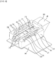
- FIG. 5 is a perspective view of FIG. 3 , from which some components are removed.
- FIG. 6 is a front view of FIG. 5 .
- FIG. 7 is a perspective view of FIG. 5 , from which some components are removed.
- FIG. 8 is a front view of FIG. 7 .
- the guide bar 240 may be provided in a plural number so as to surround the first lens group 210, the second lens group 220, and the third lens group 230.
- four guide bars 240 may be provided such that two thereof are disposed at an upper portion of a plane perpendicular to the optical-axis direction and the remaining two thereof are disposed at a lower portion of the plane so as to surround the first lens group 210, the second lens group 220, and the third lens group 230.
- the four guide bars 240 may be disposed so as to be spaced apart from each other by a predetermined spacing distance in a horizontal direction and a vertical direction in the plane perpendicular to the optical-axis direction.
- the spacing distance may be appropriately set in consideration of the diameter of the lens or the lens barrel of each lens group.
- the driving device may include a driving magnet 271 and a coil part 272.
- the driving magnet 271 and the coil part 272 may be provided at positions corresponding to each of the first mover 231-1 and the second mover 231-2.
- two driving magnets 271 for driving the first mover 231-1 and the second mover 231-2 may be spaced apart from each other in a direction perpendicular to the optical-axis direction, and may be disposed at different positions from each other in the optical-axis direction.
- two coil parts 272 which are respectively disposed opposite the two driving magnets 271 to generate electromagnetic interaction therewith, may be spaced apart from each other in a direction perpendicular to the optical-axis direction, and may be disposed at different positions from each other in the optical-axis direction.
- the two driving magnets 271 and the two coil parts 272 are disposed at different positions, they have similar structures and perform similar functions, and thus will be described collectively hereinafter.
- the driving magnet 271 may be coupled to the mover 231. It is preferable for the driving magnet 271 to be disposed further outwards than the mover 231 in a direction perpendicular to the optical-axis direction so as to be located at a position close to the coil part 272.
- the driving magnet 271 may be configured as a permanent magnet. Only one driving magnet 271 may be provided. However, in another embodiment, the driving magnet 271 may be configured as a plurality of permanent magnets stacked in a direction perpendicular to the optical-axis direction.
- the coil part 272 may be coupled to the base 250, and may be disposed opposite the driving magnet 271.
- the coil part 272 may include a yoke 272a and a moving coil 272b.
- the yoke 272a may be mounted to the base 250, and may be disposed such that the longitudinal direction thereof is oriented in the optical-axis direction.
- the moving coil 272b may be wound on the yoke 272a, and a part thereof may be disposed opposite the driving magnet 271. Since the longitudinal direction of the moving coil 272b wound on the yoke 272a is oriented in the optical-axis direction, a part of the moving coil 272b in the longitudinal direction has a linear shape.
- the coil part 272 may be disposed in a space formed in the base 250.
- opposite ends of the yoke 272a may be secured to the base 250.
- the yoke 272a and the moving coil 272b may be bonded to the base 250 using an adhesive filler.
- Opposite ends of the moving coil 272b may be electrically connected to the first printed circuit board 300, and thus the moving coil 272b may receive current from an external power source (not illustrated).
- the moving direction of the mover 231 in the optical-axis direction i.e. whether to move the mover 231 toward the first lens group 210 or to move the mover 231 in the opposite direction, i.e. toward the second lens group 220, by adjusting the direction in which the current is applied to the moving coil 272b.
- the moving direction and the moving distance of the mover 231 may be adjusted through interaction of the moving coil 272b and the driving magnet 271, whereby the camera module is capable of performing the auto-focusing and zoom-up functions.
- the third lens group 230 which is disposed between the first lens group 210 and the second lens group 220, is composed of two lens groups, and the moving directions and the moving distances of the respective lens groups are independently adjusted by the first mover 231-1 and the second mover 231-2.
- the camera module according to the embodiment is capable of efficiently and accurately performing the auto-focusing and zoom-up functions.
- FIG. 4 is a plan view of FIG. 3 .
- FIG. 11 is an enlarged view of part A in FIG. 4 .
- the device for detecting the moving position of the mover 231 in the optical-axis direction may include a sensing magnet 281, a position sensor 282, and a second printed circuit board 283.
- the second printed circuit board may be provided separately from the first printed circuit board, or may be integrally formed with the first printed circuit board.
- two pairs of sensing magnets 281 and position sensors 282 may be provided.
- the two pairs of sensing magnets 281 and position sensors 282 may be disposed separately at different positions from each other.
- two sensing magnets 281 for sensing the movement of the first mover 231-1 and the second mover 231-2 may be spaced apart from each other in a direction perpendicular to the optical-axis direction, and may be disposed at different positions from each other in the optical-axis direction.
- two position sensors 282 which are respectively disposed opposite the two sensing magnets 281, may be spaced apart from each other in a direction perpendicular to the optical-axis direction, and may be disposed at different positions from each other in the optical-axis direction.
- the sensing magnet 281 needs to be spaced apart from the driving magnet 271 in order to avoid magnetic interference with the driving magnet 271.
- the sensing magnet 281 may be spaced apart from the driving magnet 271 in a direction perpendicular to the optical-axis direction, and may be disposed at a position different from that of the driving magnet 271 in the optical-axis direction. That is, the sensing magnet 281 may be disposed so as to be spaced apart from the driving magnet 271 in the optical-axis direction and in a direction perpendicular to the optical-axis direction.
- the position sensor 282 and the second printed circuit board 283, which are disposed opposite the sensing magnet 281 may also be spaced apart from the driving magnet 271 in a direction perpendicular to the optical-axis direction, and may be disposed at positions different from the position of the driving magnet 271 in the optical-axis direction.
- the position sensor 282 may malfunction due to the current applied to the coil part 272, and it is therefore preferable for the position sensor 282 and the coil part 272 to be spaced apart from each other. Accordingly, as illustrated in FIG. 4 , the position sensor 282 may be disposed so as to be spaced apart from the coil part 272 in the optical-axis direction and in a direction perpendicular to the optical-axis direction.
- the two sensing magnets 281, the two position sensors 282, and the two printed circuit boards 283 are disposed at different positions, they have similar structures and perform similar functions, and thus will be described collectively hereinafter.
- the sensing magnet 281 may be securely coupled to the mover 231, and thus, when the mover 231 moves, the sensing magnet 281 may move together therewith in the optical-axis direction.
- the sensing magnet 281 may be configured as a permanent magnet, and may be provided in a singular number. However, the sensing magnet 281 may be formed in a structure in which a plurality of permanent magnets is stacked.
- the position sensor 282 may be coupled to the base 250, and may be disposed opposite the sensing magnet 281.
- the position sensor 282 may be configured to sense a change in the magnetic force of the sensing magnet 281, and may be configured as, for example, a hall sensor.
- the second printed circuit board 283 may be coupled to the base 250, and the position sensor 282 may be disposed so as to be coupled to the surface of the second printed circuit board 283 that faces the sensing magnet 281.
- the second printed circuit board 283 may be electrically connected to the first printed circuit board 300 to apply the current supplied from an external power source to the position sensor 282.
- the signal transmitted from the position sensor 282 may be transmitted to a controller, which is provided on the first printed circuit board 300 or is connected to the first printed circuit board 300, through the second printed circuit board 283 and the first printed circuit board 300.
- the position sensor 282 which is securely disposed at a position opposite the sensing magnet 281, may sense the change in the magnetic field of the sensing magnet 281, thereby detecting information about the movement of the mover 231, such as the moving direction or moving speed of the mover 231.
- the information about the movement of the mover 231 detected by the position sensor 282 may be transmitted to the controller, and the controller may perform feedback control of the moving direction, moving speed, and moving position of the mover 231 based on the information about the movement.
- the camera module is capable of efficiently and accurately performing auto-focusing and zoom-up functions through the feedback control of the mover 231 by the controller.
- FIG. 9 is a perspective view of FIG. 7 , from which some components are removed.
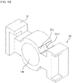
- FIG. 10 is a perspective view illustrating a third lens group 230 according to an embodiment.
- a structure including the first mover 231-1 is illustrated by way of example in FIG. 10 . Since the first mover 231-1 and the second mover 231-2 have similar structures, the first mover 231-1 and the second mover 231-2 will be hereinafter collectively referred to as a mover 231.
- the mover 231 may include a guide groove 231a in which the guide bar 240 is disposed so as to be in sliding contact therewith. Therefore, the mover 231 may be guided by the guide groove 231a to move in the optical-axis direction while maintaining sliding contact with the guide bar 240.
- the first mover may include a first magnet groove in which the driving magnet is disposed and a first sensing magnet groove in which the first sensing magnet is disposed.
- the shortest distance from the optical axis of the lens disposed in the first mover to the first magnet groove may be longer than the shortest distance from the optical axis of the lens disposed in the first mover to the first sensing magnet groove.
- the first magnet groove may be formed in the outer side of the mover with respect to the center of the lens, and the first sensing magnet groove may be formed further inwards than the first magnet groove with respect to the center of the lens.
- the mover 231 may be guided by the guide bar 240 to move linearly in the optical-axis direction, and separate rotational movement of the mover 231 and the guide bar 240 may be prevented.
- the mover 231 is provided so as to move in the optical-axis direction through sliding contact between the guide bar 240 and the mover 231, a camera module capable of efficiently performing the auto-focusing and zoom-up functions with a simple structure may be realized.
- a protruding portion 231a-1 may be formed in the guide groove 231a.
- the protruding portion 231a-1 may be in contact with the guide bar 240, and may serve to reduce the contact area with the guide bar 240.
- the protruding portion 231a-1 may protrude in a direction perpendicular to the longitudinal direction of the guide groove 231a.
- one protruding portion 231a-1 is formed in one guide groove 231a.
- two or more protruding portions 231a-1 may be formed in one guide groove 231a.
- the protruding portion 231a-1 may reduce the contact area between the guide groove 231a and the guide bar 240 to reduce the contact area between the guide bar 240 and the mover 231.
- the frictional resistance that is applied to the mover 231 by the guide bar 240 may be reduced.
- the amount of current that is applied to the moving coil 272b to move the mover 231 may be reduced.
- FIG. 6 is a front view of FIG. 5 .
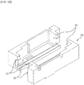
- FIG. 12 is a perspective view illustrating a base 250 according to an embodiment.
- a mounting groove 251, in which the guide bar 240 is mounted may be formed in the base 250.
- the mounting groove 251 may be formed in the longitudinal direction of the guide bar 240.
- the guide bar 240 may be mounted in the mounting groove 251.
- the guide bar 240 may be securely fitted into the mounting groove 251 using an adhesive or the like.
- the mounting groove 251 in the base 250 in which the guide bar 240 disposed at an upper portion of the base 250, among the plurality of guide bars 240, is mounted, may be formed in a portion protruding from the side surface of the base 250.
- This mounting groove 251 may be formed in a plural number in the longitudinal direction of the guide bar 240, i.e. in the optical-axis direction.
- mounting grooves 251 are formed in the upper portion of the base 250 such that two thereof are disposed in the optical-axis direction and the remaining two thereof are disposed at positions symmetrical thereto.
- the number of mounting grooves 251 formed in the upper portion of the base 250 is not limited thereto.
- the mounting groove 251 in the base 250 in which the guide bar 240 disposed at a lower portion of the base 250, among the plurality of guide bars 240, is mounted, may be formed in a portion protruding from the bottom surface of the base 250.
- This mounting groove 251 may be formed such that the longitudinal direction thereof is oriented in the longitudinal direction of the guide bar 240.
- two mounting grooves 251 are formed in the lower portion of the base 250 such that one thereof is continuously formed in the optical-axis direction and the remaining one thereof is disposed at a position symmetrical thereto.
- the lower mounting groove 251 may be composed of a plurality of sections, which are discontinuously disposed in a row in the longitudinal direction of the guide bar 240, rather than being formed in a single continuous shape.
- a camera module according to embodiments may be used in mobile devices such as mobile phones, smartphones, tablet PCs, and laptops.
Landscapes
- Physics & Mathematics (AREA)
- General Physics & Mathematics (AREA)
- Optics & Photonics (AREA)
- Engineering & Computer Science (AREA)
- Multimedia (AREA)
- Signal Processing (AREA)
- General Engineering & Computer Science (AREA)
- Lens Barrels (AREA)
Abstract
Description
- Embodiments relate to a camera module configured to perform auto-focusing and zoom-up functions.
- The content described in this section merely provides background information regarding embodiments, and does not constitute the conventional art.
- Mobile phones or smartphones equipped with camera modules that take an image or a video of an object and store the same have been developed. In general, a camera module may include a lens, an image sensor module, and a lens-moving device for adjusting the distance between the lens and the image sensor module.
- Mobile devices, such as mobile phones, smartphones, tablet PCs, and laptops, have built-in miniature camera modules. Camera modules may perform an auto-focusing function of adjusting the distance between an image sensor and a lens to control the focal length of the lens.
- Meanwhile, camera modules may also perform a zoom-up function, i.e. a function of photographing an object located a long distance away with increased magnification.
- Since miniature camera modules have a limited size, there is a problem in that it is difficult to construct miniature camera modules such that they perform a zoom-up function of the type implemented in general large-scale cameras.
- Embodiments relate to a camera module configured to perform auto-focusing and zoom-up functions.
- The objects to be accomplished by the disclosure are not limited to the above-mentioned objects, and other objects not mentioned herein will be clearly understood by those skilled in the art from the following description.
- A camera module according to an embodiment may include a prism configured to change an optical path and a moving unit disposed opposite the prism. The moving unit may include a first lens group disposed adjacent to the prism, a second lens group disposed so as to be spaced apart from the first lens group in an optical-axis direction, a third lens group disposed between the first lens group and the second lens group and configured to move in the optical-axis direction, a guide bar disposed such that the longitudinal direction thereof is oriented in the optical-axis direction and configured to be in sliding contact with the third lens group to guide movement of the third lens group, and a base to which the guide bar is mounted.
- The third lens group may include a mover, which is provided in a plural number and includes at least one lens.
- The mover may include a first mover, disposed adjacent to the first lens group, and a second mover, disposed between the first mover and the second lens group.
- The guide bar may be provided in a plural number so as to surround the first lens group, the second lens group, and the third lens group.
- The mover may include a guide groove in which the guide bar is disposed so as to be in sliding contact therewith.
- The guide groove may include a protruding portion formed to be in contact with the guide bar in order to reduce the contact area with the guide bar.
- The camera module according to an embodiment may further include a coupling member coupled to at least one end of the guide bar to fix the position of the guide bar.
- The camera module according to an embodiment may further include a driving magnet coupled to the mover and a coil part coupled to the base and disposed opposite the driving magnet.
- The coil part may include a yoke mounted to the base and disposed such that the longitudinal direction thereof is oriented in the optical-axis direction and a moving coil wound on the yoke such that a part thereof is disposed opposite the driving magnet.
- The camera module according to an embodiment may further include a sensing magnet coupled to the mover, a position sensor coupled to the base and disposed opposite the sensing magnet, and a second printed circuit board coupled to the base and configured to allow the position sensor to be mounted thereon.
- The sensing magnet may be spaced apart from the driving magnet in the optical-axis direction and in a direction perpendicular to the optical-axis direction, and the position sensor may be spaced apart from the coil part in the optical-axis direction and in a direction perpendicular to the optical-axis direction.
- The base may include a mounting groove in which the guide bar is mounted, and the mounting groove may be formed in the longitudinal direction of the guide bar.
- The camera module according to an embodiment may further include a first printed circuit board coupled to the bottom surface of the base.
- The camera module according to an embodiment may further include a cover member configured to accommodate the prism and the moving unit.
- The camera module according to an embodiment may further include an OIS correction unit, disposed between the prism and the moving unit, and a second photographing unit, spaced apart from the prism and the moving unit.
- A camera module according to an embodiment may include a base, a plurality of guide bars coupled to the base, a first mover disposed in the base and including at least one lens disposed therein, and a second mover disposed in the base and including at least one lens disposed therein. Each of the first mover and the second mover may include a plurality of guide grooves formed therein to allow the guide bars to be disposed therein, and each of the guide grooves may include a protruding portion formed to be in contact with a respective one of the guide bars.
- For example, the camera module may include a prism configured to change an optical path of external light incident thereon such that the optical path is oriented in a direction perpendicular to the direction in which the lens disposed in the first mover and the lens disposed in the second mover are aligned.
- For example, the guide bars may be disposed so as to surround the first mover and the second mover.
- For example, the camera module may further include a coupling member coupled to at least one end of each of the guide bars to fix the positions of the guide bars.
- For example, the base may include mounting grooves formed therein to allow the guide bars to be disposed therein.
- For example, the camera module may further include a first driving magnet disposed at one side of the first mover, a first coil part coupled to the base and disposed opposite the first driving magnet, a sensing magnet disposed at the opposite side of the mover, and a first position sensor coupled to the base and disposed opposite the sensing magnet.
- For example, the first sensing magnet may be spaced apart from the first driving magnet in a direction perpendicular to the optical-axis direction.
- For example, the camera module may further include a lens disposed between the prism and the first mover or between the prism and the second mover.
- For example, the camera module may further include a lens disposed between the first mover and the second mover.
- In an embodiment, a third lens group, which is disposed between a first lens group and a second lens group, is composed of two lens groups, and the moving directions and the moving distances of the respective lens groups are independently adjusted by a first mover and a second mover. Thus, a camera module according to an embodiment is capable of efficiently and accurately performing auto-focusing and zoom-up functions.
- In an embodiment, since a mover is provided so as to move in an optical-axis direction through sliding contact between a guide bar and the mover, a camera module capable of efficiently performing auto-focusing and zoom-up functions with a simple structure may be realized.
- In an embodiment, a third lens group and a second lens group are sequentially disposed behind a first lens group, and the moving directions and the moving distances of the second lens group and the third lens group are independently adjusted by a first mover and a second mover. Thus, a camera module according to an embodiment is capable of efficiently and accurately performing auto-focusing and zoom-up functions.
-
-
FIG. 1 a perspective view illustrating a camera module according to an embodiment. -
FIG. 2 is a cross-sectional view ofFIG. 1 when viewed from the side. -
FIG. 3 is a perspective view ofFIG. 1 , from which a cover member is removed. -
FIG. 4 is a plan view ofFIG. 3 . -
FIG. 5 is a perspective view ofFIG. 3 , from which some components are removed. -
FIG. 6 is a front view ofFIG. 5 . -
FIG. 7 is a perspective view ofFIG. 5 , from which some components are removed. -
FIG. 8 is a front view ofFIG. 7 . -
FIG. 9 is a perspective view ofFIG. 7 , from which some components are removed. -
FIG. 10 is a perspective view illustrating a third lens group according to an embodiment. -
FIG. 11 is an enlarged view of part A inFIG. 4 . -
FIG. 12 is a perspective view illustrating a base according to an embodiment. - Hereinafter, exemplary embodiments will be described in detail with reference to the accompanying drawings. While the disclosure is susceptible to various modifications and alternative forms, specific embodiments thereof are shown by way of example in the drawings. However, the disclosure should not be construed as being limited to the embodiments set forth herein, but on the contrary, the disclosure is to cover all modifications, equivalents, and alternatives falling within the spirit and scope of the embodiments.
- It may be understood that, although the terms "first", "second", etc. may be used herein to describe various elements, these elements are not to be limited by these terms. These terms are generally only used to distinguish one element from another. In addition, terms particularly defined in consideration of the construction and operation of the embodiments are used merely to describe the embodiments, and do not define the scope of the embodiments.
- In the following description of the embodiments, it will be understood that, when each element is referred to as being "on" or "under" another element, it can be directly on or under the other element, or can be indirectly formed such that one or more intervening elements are also present. In addition, when an element is referred to as being "on" or "under", "under the element" as well as "on the element" may be included based on the element.
- In addition, relational terms, such as "on/upper part/above" and "under/lower part/below", are used only to distinguish between one subject or element and another subject or element, without necessarily requiring or involving any physical or logical relationship or sequence between such subjects or elements.
- In the description of the embodiments, the optical-axis direction is a direction that is the same as or parallel to the direction in which a
first lens group 210 to athird lens group 230 are aligned. -
FIG. 1 is a perspective view illustrating a camera module according to an embodiment.FIG. 2 is a cross-sectional view ofFIG. 1 when viewed from the side.FIG. 3 is a perspective view ofFIG. 1 , from which acover member 400 is removed.FIG. 4 is a plan view ofFIG. 3 . - As illustrated in
FIG. 1 , a camera module may include at least one of a first photographing unit or a second photographing unit, and one thereof may be omitted. The camera module may include aprism 100, a movingunit 200, acover member 400, and a first printedcircuit board 300. In this case, a part including theprism 100 and the movingunit 200 may be the first photographing unit. The second photographingunit 600 may be disposed so as to be spaced apart from the first photographing unit including theprism 100 and the movingunit 200. - The first photographing
unit unit 600 may be independently provided to capture an image, and may be driven by one controller (not illustrated). The images captured by the first photographingunit unit 600 may be edited by the controller to be expressed as a single image. - The image edited by the controller may become a wide-angle image or a zoomed-up image with a high resolution compared with the image captured by one of the first photographing
unit unit 600. - The camera module of the embodiment may be, for example, a miniature camera module for use in smartphones, tablet PCs, or the like. Therefore, the camera module may function as a so-called dual camera, in which the first photographing
unit unit 600 are separately provided and the images captured thereby are edited to a single image. - The second photographing
unit 600 may be implemented as a general camera device. Thus, the following description will focus on the first photographing unit including theprism 100 and the movingunit 200. - The
cover member 400 may cover the entirety of the camera module to accommodate the first photographing unit, which includes theprism 100 and the movingunit 200, and the components constituting the second photographingunit 600 so as to protect these components. - The
cover member 400 may be bonded to abase 250, which accommodates theprism 100 and the movingunit 200, and may also be bonded to a housing, which accommodates the second photographingunit 600, thereby protecting the components of the camera module. - The
prism 100 may be disposed in front of the movingunit 200 to change an optical path. Referring toFIGs. 1 and2 , external light may be incident on theprism 100 in the optical-axis direction, i.e. in a direction perpendicular to the direction in which thefirst lens group 210 to thethird lens group 230 are aligned. - The optical path of the external light incident on the
prism 100 may be changed so as to be oriented in the optical-axis direction. Thus, referring toFIG. 2 , the external light may sequentially pass through thefirst lens group 210, thethird lens group 230, and thesecond lens group 220. - Referring to
FIG. 2 , theprism 100 may have a total reflection surface, which is formed so as to be oriented in an oblique direction relative to the optical-axis direction. The external light incident on theprism 100 may be totally reflected by the total reflection surface, and the optical path thereof may be changed so as to be oriented in the optical-axis direction. - The moving
unit 200 may be disposed opposite theprism 100 in the optical-axis direction so that the light emitted from theprism 100 passes through the movingunit 200 in the optical-axis direction. The movingunit 200 may implement the auto-focusing or zoom-up function of the camera module. - In addition, the camera module may include an optical image stabilization (OIS)
correction unit 500, which is disposed between theprism 100 and the movingunit 200. OIS is a function that prevents shaking of an optical image. TheOIS correction unit 500 may prevent or compensate for shaking of the image captured by the camera module due to a user's hand tremor or other disturbances, thereby improving the quality of the image. - It is preferable that the
OIS correction unit 500 be designed so as to have a small volume and to effectively perform the OIS function. Therefore, theOIS correction unit 500 may be implemented as a device including a liquid lens, which is capable of preventing shaking of an image by changing the shape of a liquid provided therein in response to current applied thereto. - The moving
unit 200 may include thefirst lens group 210, thesecond lens group 220, thethird lens group 230, aguide bar 240, and thebase 250. - The light emitted from the
prism 100 may sequentially pass through thefirst lens group 210, thethird lens group 230, and thesecond lens group 220. Although not illustrated, an image sensor may be disposed behind thesecond lens group 220. The light emitted from thesecond lens group 220 may be incident on the image sensor, and the image sensor may form an image using the incident light. - In an embodiment, the distance between the
first lens group 210, thethird lens group 230, and thesecond lens group 220 may be adjusted in order to implement auto-focusing and zoom-up with respect to an image captured by the camera module. - In an embodiment, auto-focusing and zoom-up may be implemented by moving the
third lens group 230 in the optical-axis direction to adjust the distance between thefirst lens group 210 and thethird lens group 230 and the distance between thethird lens group 230 and thesecond lens group 220. - Each of the
first lens group 210, thethird lens group 230, and thesecond lens group 220 may be configured such that one or two or more lenses are aligned in the optical-axis direction to form an optical system and are mounted in a barrel. - A further description will be made with reference to
FIGs. 2 to 4 . Thefirst lens group 210 may be disposed adjacent to theprism 100, and the light emitted from theprism 100 may enter thefirst lens group 210. - The
second lens group 220 may be spaced apart from thefirst lens group 210 in the optical-axis direction, and thethird lens group 230 may be disposed between thesecond lens group 220 and thefirst lens group 210. The light emitted from thesecond lens group 220 may enter the image sensor. - In an embodiment, the
first lens group 210 and thesecond lens group 220 may be securely mounted in the camera module so as to be prevented from being moved in the optical-axis direction. At least one of thefirst lens group 210 or thesecond lens group 220 or both of thefirst lens group 210 and thesecond lens group 220 may be omitted. - However, this is merely exemplary. In another embodiment, the
first lens group 210 and thesecond lens group 220 may be provided so as to be movable in the optical-axis direction. Hereinafter, a structure in which thefirst lens group 210 and thesecond lens group 220 are prevented from being moved in the optical-axis direction will be described. - The
third lens group 230 may be disposed between thefirst lens group 210 and thesecond lens group 220, and may be movable in the optical-axis direction. The distance between thefirst lens group 210 and thethird lens group 230 and the distance between thethird lens group 210 and thesecond lens group 220 may be adjusted by moving thethird lens group 230 in the optical-axis direction. Thereby, the camera module is capable of implementing auto-focusing and zoom-up. - The
third lens group 230 may include amover 231, which is provided in a plural number and includes at least one lens. That is, thethird lens group 230 may be configured such that a lens or a lens barrel is coupled to themover 231. - In an embodiment, the
third lens group 230 may include, for example, twomovers 231. However, the embodiment is not limited thereto, and thethird lens group 230 may include one or three ormore movers 231. Hereinafter, a configuration in which thethird lens group 230 includes twomovers 231 will be described. - As illustrated in
FIGs. 2 to 4 , themovers 231 may include a first mover 231-1, which is disposed adjacent to thefirst lens group 210, and a second mover 231-2, which is disposed between the first mover 231-1 and thesecond lens group 220. - Each of the first mover 231-1 and the second mover 231-2 may be provided corresponding to a corresponding one of
separate driving magnets 271 and a corresponding one ofseparate coil parts 272, and may be moved independently in the optical-axis direction. - That is, the operation of each of the first mover 231-1 and the second mover 231-2 may be individually controlled by a corresponding one of the
separate driving magnets 271 and a corresponding one of theseparate coil parts 272. Accordingly, in response to a control command from the controller, the first mover 231-1 and the second mover 231-2 may be controlled such that the moving distances thereof in the optical-axis direction or the moving directions thereof are different from each other. - Further, each of the first mover 231-1 and the second mover 231-2 may be provided corresponding to a corresponding one of
separate sensing magnets 281 and a corresponding one ofseparate position sensors 282, and thus the moving distance thereof in the optical-axis direction or the moving direction thereof may be independently sensed. Accordingly, the controller may independently control the movement of each of the first mover 231-1 and the second mover 231-2 based on the sensed moving distance and the moving direction of each of the first mover 231-1 and the second mover 231-2. - However, since the concrete structures of the first mover 231-1 and the second mover 231-2 are similar to each other, the first mover 231-1 and the second mover 231-2 will be hereinafter collectively referred to as a
mover 231 except where otherwise noted. - The
guide bar 240 may be disposed such that the longitudinal direction thereof is oriented in the optical-axis direction, and may serve to guide the movement of thethird lens group 230 through sliding contact with thethird lens group 230. - The
guide bar 240 may be secured to the camera module, and thethird lens group 230 may be linearly moved by themover 231 relative to theguide bar 240 in the optical-axis direction. Therefore, when themover 231 provided in thethird lens group 230 moves in the optical-axis direction, themover 231 and theguide bar 240 may be brought into sliding contact with each other. - Further, the
guide bar 240, which is disposed such that the longitudinal direction thereof is oriented in the optical-axis direction, and which guides the linear movement of themover 231 and thethird lens group 230 in the optical-axis direction, may prevent thethird lens group 230 from moving in an unintended direction. - The base 250 may accommodate the
first lens group 210 to thethird lens group 230 and theguide bar 240. In particular, theguide bar 240 may be securely mounted in thebase 250. - In order to secure the
guide bar 240 to thebase 250, acoupling member 260 may be provided. Thecoupling member 260 may be coupled to at least one end of theguide bar 240 to fix the position of theguide bar 240. - In the embodiment, four
guide bars 240 may be provided, and, referring toFIG. 3 , thecoupling member 260 may be disposed behind thesecond lens group 220, and may be coupled to one end of each of the four guide bars 240. - The
coupling member 260 may include a recess formed therein to allow the end portion of theguide bar 240 to be inserted thereinto. The end portion of theguide bar 240 may be securely fitted into the recess in an interference fit manner or using an adhesive. - In the embodiment, the recess is formed in a portion protruding from one surface of the
coupling member 260. However, in another embodiment, the recess may be concavely formed in one surface of thecoupling member 260. - Further, the
coupling member 260 is disposed behind thesecond lens group 220 and is coupled to one end of theguide bar 240. However, in another embodiment, thecoupling member 260 may be disposed in front of thefirst lens group 210, and may be coupled to the opposite end of theguide bar 240. In still another embodiment, coupling members may be disposed behind thesecond lens group 220 and in front of thefirst lens group 210, and may be coupled to opposite ends of theguide bar 240. - The
coupling member 260 may be coupled to the base 250 in order to stably fix theguide bar 240. A plurality of guide bars 240 may be disposed while maintaining a constant spacing distance therebetween in a plane perpendicular to the optical-axis direction due to engagement with thecoupling member 260. - The first printed
circuit board 300 may be coupled to the bottom surface of thebase 250. The first printedcircuit board 300 may be separately provided at each of thebase 250 of the first photographing unit and the second photographingunit 600. In another embodiment, the first printedcircuit board 300 may be implemented in the form of a unitary body, which is coupled both to thebase 250 of the first photographing unit and to the second photographingunit 600. - The first printed
circuit board 300 may be electrically connected to the movingcoil 272b and theposition sensor 282 so as to supply the current required in order to drive the camera module. In addition, the first printedcircuit board 300 may be provided with a controller, or may be electrically connected to a separately provided controller. -
FIG. 5 is a perspective view ofFIG. 3 , from which some components are removed.FIG. 6 is a front view ofFIG. 5 .FIG. 7 is a perspective view ofFIG. 5 , from which some components are removed.FIG. 8 is a front view ofFIG. 7 . - The
guide bar 240 may be provided in a plural number so as to surround thefirst lens group 210, thesecond lens group 220, and thethird lens group 230. For example, as illustrated inFIGs. 5 and6 , fourguide bars 240 may be provided such that two thereof are disposed at an upper portion of a plane perpendicular to the optical-axis direction and the remaining two thereof are disposed at a lower portion of the plane so as to surround thefirst lens group 210, thesecond lens group 220, and thethird lens group 230. - The four
guide bars 240 may be disposed so as to be spaced apart from each other by a predetermined spacing distance in a horizontal direction and a vertical direction in the plane perpendicular to the optical-axis direction. The spacing distance may be appropriately set in consideration of the diameter of the lens or the lens barrel of each lens group. - Further, a driving device for moving the
mover 231 in the optical-axis direction may be provided. The driving device may include adriving magnet 271 and acoil part 272. - Since the moving distances in the optical-axis direction or the moving directions of the first mover 231-1 and the second mover 231-2 are independently controlled, the driving
magnet 271 and thecoil part 272 may be provided at positions corresponding to each of the first mover 231-1 and the second mover 231-2. - Accordingly, as illustrated in
FIGs. 5 to 8 , two drivingmagnets 271 for driving the first mover 231-1 and the second mover 231-2 may be spaced apart from each other in a direction perpendicular to the optical-axis direction, and may be disposed at different positions from each other in the optical-axis direction. - Further, similar to the two driving
magnets 271, twocoil parts 272, which are respectively disposed opposite the two drivingmagnets 271 to generate electromagnetic interaction therewith, may be spaced apart from each other in a direction perpendicular to the optical-axis direction, and may be disposed at different positions from each other in the optical-axis direction. - As described above, although the two driving
magnets 271 and the twocoil parts 272 are disposed at different positions, they have similar structures and perform similar functions, and thus will be described collectively hereinafter. - The driving
magnet 271 may be coupled to themover 231. It is preferable for the drivingmagnet 271 to be disposed further outwards than themover 231 in a direction perpendicular to the optical-axis direction so as to be located at a position close to thecoil part 272. - The driving
magnet 271 may be configured as a permanent magnet. Only onedriving magnet 271 may be provided. However, in another embodiment, the drivingmagnet 271 may be configured as a plurality of permanent magnets stacked in a direction perpendicular to the optical-axis direction. - The
coil part 272 may be coupled to thebase 250, and may be disposed opposite the drivingmagnet 271. Thecoil part 272 may include ayoke 272a and a movingcoil 272b. - The
yoke 272a may be mounted to thebase 250, and may be disposed such that the longitudinal direction thereof is oriented in the optical-axis direction. The movingcoil 272b may be wound on theyoke 272a, and a part thereof may be disposed opposite the drivingmagnet 271. Since the longitudinal direction of the movingcoil 272b wound on theyoke 272a is oriented in the optical-axis direction, a part of the movingcoil 272b in the longitudinal direction has a linear shape. - The
coil part 272 may be disposed in a space formed in thebase 250. In order to couple thecoil part 272 to thebase 250, for example, opposite ends of theyoke 272a may be secured to thebase 250. In another embodiment, theyoke 272a and the movingcoil 272b may be bonded to the base 250 using an adhesive filler. - Opposite ends of the moving
coil 272b may be electrically connected to the first printedcircuit board 300, and thus the movingcoil 272b may receive current from an external power source (not illustrated). - When current is applied to the moving
coil 272b, an electromagnetic interaction may occur between the movingcoil 272b and the drivingmagnet 271, and themover 231, to which thedriving magnet 271 is coupled, may move in the optical-axis direction, depending on the direction in which the current is applied, according to Fleming's left-hand rule. - It is possible to adjust the moving direction of the
mover 231 in the optical-axis direction, i.e. whether to move themover 231 toward thefirst lens group 210 or to move themover 231 in the opposite direction, i.e. toward thesecond lens group 220, by adjusting the direction in which the current is applied to the movingcoil 272b. Further, it is also possible to adjust the moving distance of themover 231 in the optical-axis direction by adjusting the time period during which the current is applied to the movingcoil 272b. - As described above, the moving direction and the moving distance of the
mover 231 may be adjusted through interaction of the movingcoil 272b and the drivingmagnet 271, whereby the camera module is capable of performing the auto-focusing and zoom-up functions. - As described above, in the embodiment, the
third lens group 230, which is disposed between thefirst lens group 210 and thesecond lens group 220, is composed of two lens groups, and the moving directions and the moving distances of the respective lens groups are independently adjusted by the first mover 231-1 and the second mover 231-2. Thus, the camera module according to the embodiment is capable of efficiently and accurately performing the auto-focusing and zoom-up functions. - Hereinafter, a structure for detecting the moving position of the
mover 231 in the optical-axis direction will be described in detail with reference toFIGs. 4 and11 .FIG. 4 is a plan view ofFIG. 3 . -
FIG. 11 is an enlarged view of part A inFIG. 4 . - Referring to
FIGs. 4 and11 , the device for detecting the moving position of themover 231 in the optical-axis direction may include asensing magnet 281, aposition sensor 282, and a second printedcircuit board 283. The second printed circuit board may be provided separately from the first printed circuit board, or may be integrally formed with the first printed circuit board. - Since the moving distances in the optical-axis direction and the moving directions of the first mover 231-1 and the second mover 231-2 are independently controlled, two pairs of sensing
magnets 281 andposition sensors 282 may be provided. The two pairs of sensingmagnets 281 andposition sensors 282 may be disposed separately at different positions from each other. - Therefore, as illustrated in
FIG. 4 , two sensingmagnets 281 for sensing the movement of the first mover 231-1 and the second mover 231-2 may be spaced apart from each other in a direction perpendicular to the optical-axis direction, and may be disposed at different positions from each other in the optical-axis direction. - Further, similar to the two sensing
magnets 281, twoposition sensors 282, which are respectively disposed opposite the two sensingmagnets 281, may be spaced apart from each other in a direction perpendicular to the optical-axis direction, and may be disposed at different positions from each other in the optical-axis direction. - Meanwhile, the
sensing magnet 281 needs to be spaced apart from the drivingmagnet 271 in order to avoid magnetic interference with the drivingmagnet 271. - Accordingly, as illustrated in
FIG. 4 , thesensing magnet 281 may be spaced apart from the drivingmagnet 271 in a direction perpendicular to the optical-axis direction, and may be disposed at a position different from that of the drivingmagnet 271 in the optical-axis direction. That is, thesensing magnet 281 may be disposed so as to be spaced apart from the drivingmagnet 271 in the optical-axis direction and in a direction perpendicular to the optical-axis direction. - In addition, the
position sensor 282 and the second printedcircuit board 283, which are disposed opposite thesensing magnet 281, may also be spaced apart from the drivingmagnet 271 in a direction perpendicular to the optical-axis direction, and may be disposed at positions different from the position of the drivingmagnet 271 in the optical-axis direction. - Meanwhile, the
position sensor 282 may malfunction due to the current applied to thecoil part 272, and it is therefore preferable for theposition sensor 282 and thecoil part 272 to be spaced apart from each other. Accordingly, as illustrated inFIG. 4 , theposition sensor 282 may be disposed so as to be spaced apart from thecoil part 272 in the optical-axis direction and in a direction perpendicular to the optical-axis direction. - As described above, although the two sensing
magnets 281, the twoposition sensors 282, and the two printedcircuit boards 283 are disposed at different positions, they have similar structures and perform similar functions, and thus will be described collectively hereinafter. - The
sensing magnet 281 may be securely coupled to themover 231, and thus, when themover 231 moves, thesensing magnet 281 may move together therewith in the optical-axis direction. Thesensing magnet 281 may be configured as a permanent magnet, and may be provided in a singular number. However, thesensing magnet 281 may be formed in a structure in which a plurality of permanent magnets is stacked. - The
position sensor 282 may be coupled to thebase 250, and may be disposed opposite thesensing magnet 281. Theposition sensor 282 may be configured to sense a change in the magnetic force of thesensing magnet 281, and may be configured as, for example, a hall sensor. - The second printed
circuit board 283 may be coupled to thebase 250, and theposition sensor 282 may be disposed so as to be coupled to the surface of the second printedcircuit board 283 that faces thesensing magnet 281. The second printedcircuit board 283 may be electrically connected to the first printedcircuit board 300 to apply the current supplied from an external power source to theposition sensor 282. - The signal transmitted from the
position sensor 282 may be transmitted to a controller, which is provided on the first printedcircuit board 300 or is connected to the first printedcircuit board 300, through the second printedcircuit board 283 and the first printedcircuit board 300. - When the
sensing magnet 281 moves together with themover 231, the magnetic field of thesensing magnet 281 changes. Theposition sensor 282, which is securely disposed at a position opposite thesensing magnet 281, may sense the change in the magnetic field of thesensing magnet 281, thereby detecting information about the movement of themover 231, such as the moving direction or moving speed of themover 231. - The information about the movement of the
mover 231 detected by theposition sensor 282 may be transmitted to the controller, and the controller may perform feedback control of the moving direction, moving speed, and moving position of themover 231 based on the information about the movement. - The camera module is capable of efficiently and accurately performing auto-focusing and zoom-up functions through the feedback control of the
mover 231 by the controller. -
FIG. 9 is a perspective view ofFIG. 7 , from which some components are removed.FIG. 10 is a perspective view illustrating athird lens group 230 according to an embodiment. - A structure including the first mover 231-1 is illustrated by way of example in
FIG. 10 . Since the first mover 231-1 and the second mover 231-2 have similar structures, the first mover 231-1 and the second mover 231-2 will be hereinafter collectively referred to as amover 231. - Referring to
FIGs. 9 and10 , themover 231 may include aguide groove 231a in which theguide bar 240 is disposed so as to be in sliding contact therewith. Therefore, themover 231 may be guided by theguide groove 231a to move in the optical-axis direction while maintaining sliding contact with theguide bar 240. - Referring to
FIG. 10 , the first mover may include a first magnet groove in which the driving magnet is disposed and a first sensing magnet groove in which the first sensing magnet is disposed. The shortest distance from the optical axis of the lens disposed in the first mover to the first magnet groove may be longer than the shortest distance from the optical axis of the lens disposed in the first mover to the first sensing magnet groove. As illustrated, the first magnet groove may be formed in the outer side of the mover with respect to the center of the lens, and the first sensing magnet groove may be formed further inwards than the first magnet groove with respect to the center of the lens. - The
mover 231 may be guided by theguide bar 240 to move linearly in the optical-axis direction, and separate rotational movement of themover 231 and theguide bar 240 may be prevented. - In the embodiment, since the
mover 231 is provided so as to move in the optical-axis direction through sliding contact between theguide bar 240 and themover 231, a camera module capable of efficiently performing the auto-focusing and zoom-up functions with a simple structure may be realized. - Referring to
FIG. 6 , a protrudingportion 231a-1 may be formed in theguide groove 231a. The protrudingportion 231a-1 may be in contact with theguide bar 240, and may serve to reduce the contact area with theguide bar 240. - The protruding
portion 231a-1 may protrude in a direction perpendicular to the longitudinal direction of theguide groove 231a. In the embodiment, one protrudingportion 231a-1 is formed in oneguide groove 231a. However, in another embodiment, two or moreprotruding portions 231a-1 may be formed in oneguide groove 231a. - The protruding
portion 231a-1 may reduce the contact area between theguide groove 231a and theguide bar 240 to reduce the contact area between theguide bar 240 and themover 231. - Since the contact area between the
guide bar 240 and themover 231 is reduced by the protrudingportion 231a-1, the frictional resistance that is applied to themover 231 by theguide bar 240 may be reduced. As a result, the amount of current that is applied to the movingcoil 272b to move themover 231 may be reduced. - In addition, since the contact area between the
guide bar 240 and themover 231 is reduced by the protrudingportion 231a-1, wear of theguide bar 240 and themover 231 may be reduced, thereby accurately implementing the auto-focusing and zoom-up functions of the camera module and increasing the durability of the camera module. - Hereinafter, a structure in which the
guide bar 240 is mounted to the base 250 will be described in detail with reference toFIGs. 6 and12 .FIG. 6 is a front view ofFIG. 5 . -
FIG. 12 is a perspective view illustrating a base 250 according to an embodiment. - In order for the
guide bar 240 to be mounted to thebase 250, a mountinggroove 251, in which theguide bar 240 is mounted, may be formed in thebase 250. The mountinggroove 251 may be formed in the longitudinal direction of theguide bar 240. - The
guide bar 240 may be mounted in the mountinggroove 251. Theguide bar 240 may be securely fitted into the mountinggroove 251 using an adhesive or the like. - Referring to
FIG. 12 , the mountinggroove 251 in thebase 250, in which theguide bar 240 disposed at an upper portion of thebase 250, among the plurality of guide bars 240, is mounted, may be formed in a portion protruding from the side surface of thebase 250. This mountinggroove 251 may be formed in a plural number in the longitudinal direction of theguide bar 240, i.e. in the optical-axis direction. - In the embodiment, four mounting
grooves 251 are formed in the upper portion of the base 250 such that two thereof are disposed in the optical-axis direction and the remaining two thereof are disposed at positions symmetrical thereto. However, the number of mountinggrooves 251 formed in the upper portion of thebase 250 is not limited thereto. - Further, referring to
FIG. 12 , the mountinggroove 251 in thebase 250, in which theguide bar 240 disposed at a lower portion of thebase 250, among the plurality of guide bars 240, is mounted, may be formed in a portion protruding from the bottom surface of thebase 250. This mountinggroove 251 may be formed such that the longitudinal direction thereof is oriented in the longitudinal direction of theguide bar 240. - In the embodiment, two mounting
grooves 251 are formed in the lower portion of the base 250 such that one thereof is continuously formed in the optical-axis direction and the remaining one thereof is disposed at a position symmetrical thereto. However, in another embodiment, thelower mounting groove 251 may be composed of a plurality of sections, which are discontinuously disposed in a row in the longitudinal direction of theguide bar 240, rather than being formed in a single continuous shape. - Although only a limited number of embodiments have been described above, various other embodiments are possible. The technical contents of the above-described embodiments may be combined into various forms as long as they are not incompatible with one another, and thus may be implemented in new embodiments.
- Various embodiments have been described in the best mode for carrying out the disclosure.
- A camera module according to embodiments may be used in mobile devices such as mobile phones, smartphones, tablet PCs, and laptops.
Claims (10)
- A camera module, comprising:a base;a plurality of guide bars coupled to the base;a first mover disposed in the base, the first mover comprising at least one lens disposed therein; anda second mover disposed in the base, the second mover comprising at least one lens disposed therein,wherein each of the first mover and the second mover comprises a plurality of guide grooves formed therein to allow the guide bars to be disposed therein, andwherein each of the plurality of guide grooves comprises a protruding portion formed to be in contact with a respective one of the guide bars.
- The camera module according to claim 1, comprising:
a prism configured to change an optical path of external light incident thereon such that the optical path is oriented in a direction perpendicular to a direction in which the lens disposed in the first mover and the lens disposed in the second mover are aligned. - The camera module according to claim 1, wherein the guide bars are disposed so as to surround the first mover and the second mover.
- The camera module according to claim 1, further comprising:
a coupling member coupled to at least one end of each of the guide bars to fix positions of the guide bars. - The camera module according to claim 1, wherein the base comprises mounting grooves formed therein to allow the guide bars to be disposed therein.
- The camera module according to claim 1, further comprising:a first driving magnet disposed at one side of the first mover;a first coil part coupled to the base and disposed opposite the first driving magnet;a sensing magnet disposed at an opposite side of the first mover; anda first position sensor coupled to the base and disposed opposite the sensing magnet.
- The camera module according to claim 6, wherein the first sensing magnet is spaced apart from the first driving magnet in a direction perpendicular to an optical-axis direction.
- The camera module according to claim 2, further comprising:
a lens disposed between the prism and the first mover or between the prism and the second mover. - The camera module according to claim 2, further comprising:
a lens disposed between the first mover and the second mover. - The camera module according to claim 1, wherein the first mover and the second mover are disposed so as to move in an optical-axis direction through sliding contact with the guide bars.
Applications Claiming Priority (2)
| Application Number | Priority Date | Filing Date | Title |
|---|---|---|---|
| KR1020180011062A KR102527790B1 (en) | 2018-01-30 | 2018-01-30 | Camera module |
| PCT/KR2019/000912 WO2019151700A1 (en) | 2018-01-30 | 2019-01-22 | Camera module |
Publications (2)
| Publication Number | Publication Date |
|---|---|
| EP3748429A1 true EP3748429A1 (en) | 2020-12-09 |
| EP3748429A4 EP3748429A4 (en) | 2021-11-03 |
Family
ID=67479337
Family Applications (1)
| Application Number | Title | Priority Date | Filing Date |
|---|---|---|---|
| EP19747671.6A Pending EP3748429A4 (en) | 2018-01-30 | 2019-01-22 | CAMERA MODULE |
Country Status (5)
| Country | Link |
|---|---|
| US (1) | US12591106B2 (en) |
| EP (1) | EP3748429A4 (en) |
| KR (1) | KR102527790B1 (en) |
| CN (1) | CN111684353B (en) |
| WO (1) | WO2019151700A1 (en) |
Cited By (1)
| Publication number | Priority date | Publication date | Assignee | Title |
|---|---|---|---|---|
| EP4236275A4 (en) * | 2020-11-26 | 2024-06-05 | Huawei Technologies Co., Ltd. | Camera module, motor structure, and electronic device |
Families Citing this family (9)
| Publication number | Priority date | Publication date | Assignee | Title |
|---|---|---|---|---|
| CN110879448A (en) * | 2019-11-04 | 2020-03-13 | 中国科学院西安光学精密机械研究所 | Continuous zooming device and assembling method thereof |
| KR102834426B1 (en) * | 2020-03-11 | 2025-07-15 | 엘지이노텍 주식회사 | Camera actuator and camera device comprising the same |
| KR102941677B1 (en) | 2020-04-09 | 2026-03-20 | 엘지이노텍 주식회사 | Camera actuator and camera module including the same |
| CN113890965B (en) | 2020-07-01 | 2025-10-03 | 华为技术有限公司 | Linkage device, camera module and electronic equipment |
| US11815736B2 (en) * | 2020-09-15 | 2023-11-14 | Tdk Taiwan Corp. | Optical element driving mechanism |
| CN114721111B (en) * | 2020-12-18 | 2023-08-11 | 宁波舜宇光电信息有限公司 | Optical zoom camera module |
| TWI771020B (en) * | 2021-05-26 | 2022-07-11 | 大陸商信泰光學(深圳)有限公司 | Lens driving devices and driving methods thereof |
| CN113905167B (en) * | 2021-10-15 | 2024-02-27 | 维沃移动通信有限公司 | Camera modules and electronic equipment |
| CN117375356A (en) * | 2022-07-01 | 2024-01-09 | 华为技术有限公司 | Motors, camera modules and electronic equipment |
Family Cites Families (36)
| Publication number | Priority date | Publication date | Assignee | Title |
|---|---|---|---|---|
| US4420193A (en) | 1981-08-11 | 1983-12-13 | Hiroshi Teramachi | Linear ball bearing unit |
| US5225941A (en) * | 1990-07-03 | 1993-07-06 | Canon Kabushiki Kaisha | Driving device |
| JP3240845B2 (en) * | 1994-07-15 | 2001-12-25 | ミノルタ株式会社 | Optical element position detecting device in lens device |
| JPH09191665A (en) | 1996-01-04 | 1997-07-22 | Minolta Co Ltd | Liner driving mechanism having electromechanical transducing element |
| CN1211684C (en) * | 2001-12-04 | 2005-07-20 | 财团法人工业技术研究院 | Adjustable mirror group device |
| JP2004219440A (en) * | 2003-01-09 | 2004-08-05 | Fuji Photo Film Co Ltd | Lens driving device |
| KR100557040B1 (en) * | 2003-12-30 | 2006-03-03 | 엘지전자 주식회사 | Optical pickup system |
| JP2007049878A (en) * | 2005-08-12 | 2007-02-22 | Fujinon Corp | Actuator |
| US7531773B2 (en) | 2005-09-08 | 2009-05-12 | Flextronics Ap, Llc | Auto-focus and zoom module having a lead screw with its rotation results in translation of an optics group |
| CN2901351Y (en) * | 2006-06-07 | 2007-05-16 | 力相光学股份有限公司 | Miniature Optical Zoom Lens Device |
| CN101324692A (en) * | 2007-06-12 | 2008-12-17 | 展讯通信(上海)有限公司 | An optical zoom lens control device |
| TWI343164B (en) * | 2007-12-04 | 2011-06-01 | Ind Tech Res Inst | Voice coil motor |
| CN101483376B (en) | 2008-01-10 | 2011-05-18 | 财团法人工业技术研究院 | Voice coil motor |
| JP5004830B2 (en) * | 2008-02-29 | 2012-08-22 | キヤノン株式会社 | Lens driving device, lens barrel and optical instrument |
| JP2009229682A (en) * | 2008-03-21 | 2009-10-08 | Tamron Co Ltd | Lens holding frame, lens driving apparatus and imaging apparatus |
| JP2009294454A (en) * | 2008-06-05 | 2009-12-17 | Canon Inc | Lens barrel and camera |
| JP4402163B1 (en) | 2009-04-06 | 2010-01-20 | 株式会社オプトエレクトロニクス | Liquid lens optical body and optical information reader |
| KR101552481B1 (en) * | 2009-04-13 | 2015-09-21 | 삼성전자 주식회사 | Zoom Lens Module |
| JP5546188B2 (en) * | 2009-09-18 | 2014-07-09 | キヤノン株式会社 | Lens barrel and imaging device having the same |
| JP2012019656A (en) * | 2010-07-09 | 2012-01-26 | Konica Minolta Opto Inc | Driver, image blur correction device and imaging device using the same |
| EP2690476A4 (en) * | 2011-03-24 | 2014-11-05 | Fujifilm Corp | Lens device |
| US8577217B2 (en) * | 2011-09-12 | 2013-11-05 | TOK Taiwan Corp. | Tilt preventing structure for electromagnetic driving device |
| KR101949730B1 (en) | 2011-10-19 | 2019-02-19 | 엘지전자 주식회사 | Zoom Lens Assembly and Mobile Terminal comprising the same |
| TWI471596B (en) * | 2012-02-09 | 2015-02-01 | Altek Corp | Zoom lens structure and image capturing device thereof |
| KR20130097429A (en) * | 2012-02-24 | 2013-09-03 | 삼성전자주식회사 | Focusing apparatus for optical device |
| CN103293628A (en) * | 2012-03-01 | 2013-09-11 | 华晶科技股份有限公司 | Zooming and focusing mechanism and image capturing device thereof |
| KR20140036448A (en) | 2012-09-14 | 2014-03-26 | 쓰리에이치비젼주식회사 | Camera lens module |
| US20140125948A1 (en) * | 2012-11-02 | 2014-05-08 | Carsten Feiertag | Positioning Unit And Observation Device |
| KR101446397B1 (en) | 2012-11-30 | 2014-10-01 | 엘지이노텍 주식회사 | Camera Module |
| JP2015099361A (en) * | 2013-10-17 | 2015-05-28 | Hoya株式会社 | Imaging device |
| EP3713062B1 (en) | 2013-12-23 | 2025-08-27 | Lg Innotek Co., Ltd. | Lens moving apparatus |
| KR102319554B1 (en) * | 2014-08-20 | 2021-11-01 | 엘지이노텍 주식회사 | Lens moving unit and camera module including the same |
| EP3115819B1 (en) | 2014-03-05 | 2020-05-13 | LG Innotek Co., Ltd. | Lens driving device and camera module comprising same |
| KR101586238B1 (en) | 2014-04-02 | 2016-01-18 | (주)옵티스 | Camera module for adjusting lens focus using protrusions and guide grooves |
| KR101624241B1 (en) | 2015-05-18 | 2016-05-25 | (주)아이엠 | Actuator for camera module |
| KR101751132B1 (en) * | 2015-11-03 | 2017-06-26 | 삼성전기주식회사 | Camera module |
-
2018
- 2018-01-30 KR KR1020180011062A patent/KR102527790B1/en active Active
-
2019
- 2019-01-22 EP EP19747671.6A patent/EP3748429A4/en active Pending
- 2019-01-22 CN CN201980011002.1A patent/CN111684353B/en active Active
- 2019-01-22 US US16/965,957 patent/US12591106B2/en active Active
- 2019-01-22 WO PCT/KR2019/000912 patent/WO2019151700A1/en not_active Ceased
Cited By (1)
| Publication number | Priority date | Publication date | Assignee | Title |
|---|---|---|---|---|
| EP4236275A4 (en) * | 2020-11-26 | 2024-06-05 | Huawei Technologies Co., Ltd. | Camera module, motor structure, and electronic device |
Also Published As
| Publication number | Publication date |
|---|---|
| US12591106B2 (en) | 2026-03-31 |
| CN111684353B (en) | 2022-09-20 |
| KR20190091911A (en) | 2019-08-07 |
| EP3748429A4 (en) | 2021-11-03 |
| CN111684353A (en) | 2020-09-18 |
| KR102527790B1 (en) | 2023-04-28 |
| US20210041658A1 (en) | 2021-02-11 |
| WO2019151700A1 (en) | 2019-08-08 |
Similar Documents
| Publication | Publication Date | Title |
|---|---|---|
| US12591106B2 (en) | Camera module | |
| US12126886B2 (en) | Camera module | |
| EP3742225B1 (en) | Lens assembly and camera module including the same | |
| KR102207152B1 (en) | Reflection midule and camera module including the same | |
| KR102421070B1 (en) | Lens moving unit and camera module having the same | |
| KR20210060392A (en) | Camera module | |
| KR20200144260A (en) | Reflection module and camera module including the same | |
| KR20200126871A (en) | Camera module | |
| JP7607629B2 (en) | Camera Actuator | |
| KR102338257B1 (en) | Camera module | |
| KR102255271B1 (en) | Camera module | |
| KR102742263B1 (en) | Lens Actuator and Camera module including the same | |
| US12200335B2 (en) | Camera actuator and camera device comprising same | |
| KR102233934B1 (en) | Mirror Module for OIS and Camera module including the same | |
| KR20210011269A (en) | Lens assembly moving device and camera module including the same | |
| KR20200142876A (en) | Lens assembly moving device and camera module including the same | |
| KR102457388B1 (en) | camera module | |
| KR20220023194A (en) | Camera actuator and camera module including the same | |
| KR20210081022A (en) | Camera actuator and camera module comprising the same | |
| EP4653945A1 (en) | Camera actuator and camera module including same | |
| KR20240021099A (en) | Lens driving apparatus and camera module including the same | |
| KR20240112176A (en) | Reflection module and camera module including the same |
Legal Events
| Date | Code | Title | Description |
|---|---|---|---|
| STAA | Information on the status of an ep patent application or granted ep patent |
Free format text: STATUS: THE INTERNATIONAL PUBLICATION HAS BEEN MADE |
|
| PUAI | Public reference made under article 153(3) epc to a published international application that has entered the european phase |
Free format text: ORIGINAL CODE: 0009012 |
|
| STAA | Information on the status of an ep patent application or granted ep patent |
Free format text: STATUS: REQUEST FOR EXAMINATION WAS MADE |
|
| 17P | Request for examination filed |
Effective date: 20200827 |
|
| AK | Designated contracting states |
Kind code of ref document: A1 Designated state(s): AL AT BE BG CH CY CZ DE DK EE ES FI FR GB GR HR HU IE IS IT LI LT LU LV MC MK MT NL NO PL PT RO RS SE SI SK SM TR |
|
| AX | Request for extension of the european patent |
Extension state: BA ME |
|
| DAV | Request for validation of the european patent (deleted) | ||
| DAX | Request for extension of the european patent (deleted) | ||
| A4 | Supplementary search report drawn up and despatched |
Effective date: 20210930 |
|
| RIC1 | Information provided on ipc code assigned before grant |
Ipc: G03B 30/00 20210101ALI20210924BHEP Ipc: G03B 17/17 20210101ALI20210924BHEP Ipc: G03B 3/10 20210101ALI20210924BHEP Ipc: G02B 7/10 20210101ALI20210924BHEP Ipc: G02B 26/08 20060101ALI20210924BHEP Ipc: H04N 5/225 20060101ALI20210924BHEP Ipc: G03B 13/36 20210101ALI20210924BHEP Ipc: G03B 5/00 20210101ALI20210924BHEP Ipc: G03B 17/12 20210101AFI20210924BHEP |
|
| STAA | Information on the status of an ep patent application or granted ep patent |
Free format text: STATUS: EXAMINATION IS IN PROGRESS |
|
| 17Q | First examination report despatched |
Effective date: 20230630 |