EP3748332A1 - Inspection flow channel device and inspection apparatus - Google Patents
Inspection flow channel device and inspection apparatus Download PDFInfo
- Publication number
- EP3748332A1 EP3748332A1 EP19748305.0A EP19748305A EP3748332A1 EP 3748332 A1 EP3748332 A1 EP 3748332A1 EP 19748305 A EP19748305 A EP 19748305A EP 3748332 A1 EP3748332 A1 EP 3748332A1
- Authority
- EP
- European Patent Office
- Prior art keywords
- flow path
- path device
- inspection
- flow
- opening
- Prior art date
- Legal status (The legal status is an assumption and is not a legal conclusion. Google has not performed a legal analysis and makes no representation as to the accuracy of the status listed.)
- Withdrawn
Links
Images





Classifications
-
- B—PERFORMING OPERATIONS; TRANSPORTING
- B01—PHYSICAL OR CHEMICAL PROCESSES OR APPARATUS IN GENERAL
- B01L—CHEMICAL OR PHYSICAL LABORATORY APPARATUS FOR GENERAL USE
- B01L3/00—Containers or dishes for laboratory use, e.g. laboratory glassware; Droppers
- B01L3/50—Containers for the purpose of retaining a material to be analysed, e.g. test tubes
- B01L3/502—Containers for the purpose of retaining a material to be analysed, e.g. test tubes with fluid transport, e.g. in multi-compartment structures
- B01L3/5027—Containers for the purpose of retaining a material to be analysed, e.g. test tubes with fluid transport, e.g. in multi-compartment structures by integrated microfluidic structures, i.e. dimensions of channels and chambers are such that surface tension forces are important, e.g. lab-on-a-chip
- B01L3/502761—Containers for the purpose of retaining a material to be analysed, e.g. test tubes with fluid transport, e.g. in multi-compartment structures by integrated microfluidic structures, i.e. dimensions of channels and chambers are such that surface tension forces are important, e.g. lab-on-a-chip specially adapted for handling suspended solids or molecules independently from the bulk fluid flow, e.g. for trapping or sorting beads or physically stretching molecules
-
- B—PERFORMING OPERATIONS; TRANSPORTING
- B01—PHYSICAL OR CHEMICAL PROCESSES OR APPARATUS IN GENERAL
- B01D—SEPARATION
- B01D43/00—Separating particles from liquids, or liquids from solids, otherwise than by sedimentation or filtration
-
- G—PHYSICS
- G01—MEASURING; TESTING
- G01N—INVESTIGATING OR ANALYSING MATERIALS BY DETERMINING THEIR CHEMICAL OR PHYSICAL PROPERTIES
- G01N15/00—Investigating characteristics of particles; Investigating permeability, pore-volume or surface-area of porous materials
- G01N15/10—Investigating individual particles
- G01N15/14—Optical investigation techniques, e.g. flow cytometry
- G01N15/1404—Handling flow, e.g. hydrodynamic focusing
-
- G—PHYSICS
- G01—MEASURING; TESTING
- G01N—INVESTIGATING OR ANALYSING MATERIALS BY DETERMINING THEIR CHEMICAL OR PHYSICAL PROPERTIES
- G01N15/00—Investigating characteristics of particles; Investigating permeability, pore-volume or surface-area of porous materials
- G01N15/10—Investigating individual particles
- G01N15/14—Optical investigation techniques, e.g. flow cytometry
- G01N15/1484—Optical investigation techniques, e.g. flow cytometry microstructural devices
-
- B—PERFORMING OPERATIONS; TRANSPORTING
- B01—PHYSICAL OR CHEMICAL PROCESSES OR APPARATUS IN GENERAL
- B01L—CHEMICAL OR PHYSICAL LABORATORY APPARATUS FOR GENERAL USE
- B01L2200/00—Solutions for specific problems relating to chemical or physical laboratory apparatus
- B01L2200/06—Fluid handling related problems
- B01L2200/0636—Focussing flows, e.g. to laminate flows
-
- B—PERFORMING OPERATIONS; TRANSPORTING
- B01—PHYSICAL OR CHEMICAL PROCESSES OR APPARATUS IN GENERAL
- B01L—CHEMICAL OR PHYSICAL LABORATORY APPARATUS FOR GENERAL USE
- B01L2200/00—Solutions for specific problems relating to chemical or physical laboratory apparatus
- B01L2200/06—Fluid handling related problems
- B01L2200/0647—Handling flowable solids, e.g. microscopic beads, cells, particles
- B01L2200/0652—Sorting or classification of particles or molecules
-
- B—PERFORMING OPERATIONS; TRANSPORTING
- B01—PHYSICAL OR CHEMICAL PROCESSES OR APPARATUS IN GENERAL
- B01L—CHEMICAL OR PHYSICAL LABORATORY APPARATUS FOR GENERAL USE
- B01L2300/00—Additional constructional details
- B01L2300/06—Auxiliary integrated devices, integrated components
- B01L2300/0627—Sensor or part of a sensor is integrated
- B01L2300/0654—Lenses; Optical fibres
-
- B—PERFORMING OPERATIONS; TRANSPORTING
- B01—PHYSICAL OR CHEMICAL PROCESSES OR APPARATUS IN GENERAL
- B01L—CHEMICAL OR PHYSICAL LABORATORY APPARATUS FOR GENERAL USE
- B01L2300/00—Additional constructional details
- B01L2300/06—Auxiliary integrated devices, integrated components
- B01L2300/0681—Filter
-
- B—PERFORMING OPERATIONS; TRANSPORTING
- B01—PHYSICAL OR CHEMICAL PROCESSES OR APPARATUS IN GENERAL
- B01L—CHEMICAL OR PHYSICAL LABORATORY APPARATUS FOR GENERAL USE
- B01L2300/00—Additional constructional details
- B01L2300/08—Geometry, shape and general structure
- B01L2300/0809—Geometry, shape and general structure rectangular shaped
- B01L2300/0816—Cards, e.g. flat sample carriers usually with flow in two horizontal directions
-
- B—PERFORMING OPERATIONS; TRANSPORTING
- B01—PHYSICAL OR CHEMICAL PROCESSES OR APPARATUS IN GENERAL
- B01L—CHEMICAL OR PHYSICAL LABORATORY APPARATUS FOR GENERAL USE
- B01L2300/00—Additional constructional details
- B01L2300/08—Geometry, shape and general structure
- B01L2300/0887—Laminated structure
-
- B—PERFORMING OPERATIONS; TRANSPORTING
- B01—PHYSICAL OR CHEMICAL PROCESSES OR APPARATUS IN GENERAL
- B01L—CHEMICAL OR PHYSICAL LABORATORY APPARATUS FOR GENERAL USE
- B01L2300/00—Additional constructional details
- B01L2300/16—Surface properties and coatings
- B01L2300/168—Specific optical properties, e.g. reflective coatings
-
- G—PHYSICS
- G01—MEASURING; TESTING
- G01N—INVESTIGATING OR ANALYSING MATERIALS BY DETERMINING THEIR CHEMICAL OR PHYSICAL PROPERTIES
- G01N15/00—Investigating characteristics of particles; Investigating permeability, pore-volume or surface-area of porous materials
- G01N15/10—Investigating individual particles
- G01N15/14—Optical investigation techniques, e.g. flow cytometry
- G01N15/149—Optical investigation techniques, e.g. flow cytometry specially adapted for sorting particles, e.g. by their size or optical properties
-
- G—PHYSICS
- G01—MEASURING; TESTING
- G01N—INVESTIGATING OR ANALYSING MATERIALS BY DETERMINING THEIR CHEMICAL OR PHYSICAL PROPERTIES
- G01N15/00—Investigating characteristics of particles; Investigating permeability, pore-volume or surface-area of porous materials
- G01N15/01—Investigating characteristics of particles; Investigating permeability, pore-volume or surface-area of porous materials specially adapted for biological cells, e.g. blood cells
- G01N2015/016—White blood cells
-
- G—PHYSICS
- G01—MEASURING; TESTING
- G01N—INVESTIGATING OR ANALYSING MATERIALS BY DETERMINING THEIR CHEMICAL OR PHYSICAL PROPERTIES
- G01N15/00—Investigating characteristics of particles; Investigating permeability, pore-volume or surface-area of porous materials
- G01N15/10—Investigating individual particles
- G01N2015/1006—Investigating individual particles for cytology
-
- G—PHYSICS
- G01—MEASURING; TESTING
- G01N—INVESTIGATING OR ANALYSING MATERIALS BY DETERMINING THEIR CHEMICAL OR PHYSICAL PROPERTIES
- G01N15/00—Investigating characteristics of particles; Investigating permeability, pore-volume or surface-area of porous materials
- G01N15/10—Investigating individual particles
- G01N2015/1028—Sorting particles
Definitions
- the present disclosure relates to an inspection flow path device and an inspection apparatus.
- a separation and recovery of microparticles are conventionally known (refer to Japanese Patent Application Laid-Open No. 2012-76016 ).
- a measurement of microparticles is known.
- the separation and recovery of the microparticles and the measurement of the microparticles are separately performed in performing an inspection on the microparticles.
- a work efficiency of the inspection can be improved.
- An inspection flow path device comprises a first flow path device and a second flow path device connected to the first flow path device.
- the first flow path device has a plate-like shape and includes a pair of first surfaces located opposite to each other in a thickness direction and a first flow path located inside and including a first opening located in the first surface and a branch flow path.
- the second flow path device has a plate-like shape and translucency and includes a pair of second surfaces located opposite to each other in a thickness direction and a second flow path located inside and including a second opening located in the second surface.
- One of the pair of first surfaces of the first flow path device is located to face one of the pair of second surfaces of the second flow path device, and the first opening and the second opening facing each other are connected to each other.
- An inspection apparatus includes the inspection flow path device described above and an optical sensor irradiating the second flow path of the second flow path device in the inspection flow path device with light and receiving light passing through the second flow path.
- the work efficiency can be improved.
- a rectangular coordinate system (X, Y, Z) is defined for descriptive purposes to define a positive side in a Z axis direction as an upper side, however, in the present invention, any direction may be the upper side or a lower side.
- X, Y, Z a rectangular coordinate system
- any direction may be the upper side or a lower side.
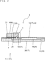
- Fig. 1 and Fig. 2 schematically illustrate an inspection flow path device 1.
- Fig. 1 is a top view of the inspection flow path device 1
- Fig. 2 is a cross-sectional view of the inspection flow path device 1 cut along an A-A line in Fig. 1 .
- the inspection flow path device 1 can separate and recovery a specific component (microparticles) in the sample, and measure the recovered specific component (microparticles).
- the inspection flow path device 1 can separate and recover white blood cells (leukocyte) from blood, and measure the number of white blood cells included in the blood.
- the inspection flow path device 1 includes a first flow path device 2 and a second flow path device 3 connected to the first flow path device 2.
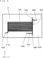
- Fig. 3 schematically illustrates the first flow path device 2.
- Fig. 3 is a plan view of the first flow path device 2 when seen from an upper surface transparently.
- the first flow path device 2 can separate and recovery microparticles in a fluid (sample).
- the first flow path device 2 includes a first flow path 4.
- the first flow path 4 includes a main flow path (first main flow path) 5 and a branch flow path (first branch flow path) 6 branching from the first main flow path 5.
- the fluid flowing in the first flow path device 2 flows into the first main flow path 5, and only microparticles (second particles) different from the specific microparticles (first particles) flow from the first main flow path 5 into the first branch flow path 6, thus the specific microparticles (first particles) can be separated.
- the first flow path device 1 can also separate the different microparticles (second particles).
- the first branch flow path 6 is designed so that only the second particles are branched and flow therein, however, only the second particles are not necessarily branched. That is to say, microparticles different from the second particles may flow into the first branch flow path 6 in some cases.
- Fig. 4 schematically illustrates a process of separating the first particles and the second particles.
- Fig. 4 is an enlarged view of a broken line section in Fig. 3 .
- a large circle in Fig. 4 indicates the first particle PI and a small circle indicates the second particle P2.
- a thick arrow along the X axis direction indicates a main stream and a thin arrow along the Y axis direction indicates a "pressing flow” described hereinafter.
- a hatched region in Fig. 4 indicates a "lead-in flow” described hereinafter.
- the first flow path 4 in the present disclosure includes one first main flow path 5 and the plurality of first branch flow path 6 connected to one side of the one first main flow path 5.
- a sectional area and length of each of the first main flow path 5 and the first branch flow path 6, a flow rate of the sample and the like are adjusted, thus the "lead-in flow", which flows from the first main flow path 5 into the first branch flow path 6 can be generated in the first main flow path 5.
- the first flow path device 2 generates the pressing flow, which can press the sample flowing in the first main flow path 5 against a side of the first branch flow path 6, in the first flow path 4.
- a width of the lead-in flow is set to larger than a barycentric position of the specific microparticle (the first particle PI) flowing in the sample and smaller than a barycentric position of the other microparticle (the second particle P2), thus the other microparticles (the second particle P2) can be lead in the first branch flow path 6.
- a width of the first branch flow path 6 is set to smaller than a size of the specific microparticle (the first particle PI) flowing in the sample and larger than a size of the other microparticle (the second particle P2), thus the other microparticles (the second particle P2) can be lead in the first branch flow path 6.
- the first flow path device 2 in the present disclosure is particularly intended to separate red blood cells (erythrocyte) and white blood cells (leukocyte) in blood.
- a barycentric position of the red blood cell in the blood is located 2 to 2.5 ⁇ m from an edge thereof, for example, and the size of the red blood cell is 6 to 8 ⁇ m, for example.
- a barycentric position of the white blood cell is located 5 to 10 ⁇ m from an edge thereof, for example, and the size of the white blood cell is 10 to 30 ⁇ m, for example.
- the first main flow path 5 may have the sectional area ranging from 300 ⁇ m 2 to 1000 ⁇ m 2 and the length ranging from 0.5 mm to 20 mm, for example.
- the first branch flow path 6 may have the sectional area ranging from 100 ⁇ m 2 to 500 ⁇ m 2 and the length ranging from 3 mm to 25 mm, for example.
- the flow rate in the first flow path 4 may be equal to or larger than 0.2 m/s and equal to or smaller than 5 m/s, for example.
- the width of the lead-in flow can be set equal to or larger than 2 ⁇ m and equal to or smaller than 15 ⁇ m, for example, thus the red blood cell and the white blood cell in the blood can be separated.
- the first flow path 4 further includes a first recovery flow path 7 connected to the first main flow path 5, and can recovery the first particles PI.
- the first particles P1 can be recovered in the first recovery flow path 7 using the pressing flow.
- the first flow path 4 may include a first disposal flow path 7' connected to the plurality of first branch flow paths 6.
- the first disposal flow path 7' may recover or dispose of the separated second particles P2.
- one first disposal flow path 7' to which the plurality of first branch flow paths 6 are connected functions as a flow path for recovering the second particles P2.
- the fluid flowing to an end of the first main flow path 5 may be disposed of.
- the first flow path device 2 is a plate-like member.
- the first flow path 4 is located inside the plate-like member.
- the first flow path device 2 includes a pair of first surfaces 8 located opposite to each other in a thickness direction (the Z axis direction).
- the first flow path 4 is opened in the pair of first surfaces 8.
- the first flow path 4 includes a plurality of first openings 9 located in the pair of first surfaces 8.
- one of the pair of first surfaces 8 is defined as a first upper surface 10 and the other one thereof is defined as a first lower surface 11 for descriptive purposes.
- the first upper surface 10 is a surface located on a positive side of the Z axis and the first lower surface 11 is a surface located on a negative side of the Z axis.
- at least one of the plurality of first openings 9 is located in the first lower surface 11.
- the plurality of first openings 9 include a first flow inlet (first sample flow inlet) 12 through which the sample flows into at least the first main flow path 5, a first flow outlet (a first sample flow outlet) 13 through which the first particles P1 are recovered from the first recovery flow path 7, and at least one first disposal flow outlet 14 through which constituents in which the first particles P1 are removed from the sample are recovered.
- a first pressing flow inlet 15 through which the fluid of the pressing flow for pressing the sample against the first branch flow path 6 side flows.
- the first disposal flow outlet 14 is connected to the first main flow path 5 and the first disposal flow path 7'. The fluid flowing out through the first disposal flow outlet 14 is recovered through a through hole 14' formed in the second flow path device 3.
- a planar shape of the first flow path device 2 in the present disclosure is a rectangular shape.
- Each of the first surfaces 8 in the present disclosure is a flat surface.
- a planar shape of the first flow path device 2 is not limited to the rectangular shape.
- Each of the first surfaces 8 in the present disclosure is not limited to the flat surface.
- shapes of the first upper surface 10 and the first lower surface 11 may be different from each other.
- the first flow path device 2 may be formed of a material of polydimethylsiloxane (PDMS) or acrylic (PMMA), for example.
- a thickness of the first flow path device 2 may be equal to or larger than 1 mm and equal to or smaller than 5 mm, for example.
- the planar shape of the first flow path device 2 may have a short side with a length equal to or larger than 10 mm and equal to or smaller than 30 mm and a long side with a length equal to or larger than 10 mm and equal to or smaller than 50 mm, for example.
- the first flow path device 2 can be formed by preparing two substrates, forming a groove in one of the two substrates, and attaching the two substrates to each other to cover the groove, for example.
- the second flow path device 3 is a flow path for measuring the specific microparticles separated and recovered in the first flow path device 2.
- the second flow path device 3 includes a second flow path 16 connected to the first flow path 4 in the first flow path device 2.
- the second flow path device 3 has translucency.
- the second flow path device 3 can flow the specific microparticles separated and recovered in the first flow path device 2 to the second flow path 16 and measure the specific microparticles using an optical sensor described hereinafter.
- the second flow path device 3 measures intensity of light passing through the second flow path 16, thereby measuring the specific microparticles.
- the second flow path device 3 is a plate-like member.
- the second flow path 16 is located inside the plate-like member.
- the second flow path device 3 includes a pair of second surfaces 17 located opposite to each other in a thickness direction (the Z axis direction).
- the second flow path 16 is opened in the pair of second surfaces 17.
- the second flow path 16 includes a plurality of second openings 18 located in the pair of second surfaces 17.
- one of the pair of second surfaces 17 is defined as a second upper surface 19 and the other one thereof is defined as a second lower surface 20 for descriptive purposes.
- the second upper surface 19 is a surface located on a positive side of the Z axis and the second lower surface 20 is a surface located on a negative side of the Z axis.
- a planar shape of the second flow path device 3 in the present disclosure is a rectangular shape.
- Each of the second surfaces 17 in the present disclosure is a flat surface.
- a planar shape of the second flow path device 3 is not limited to the rectangular shape.
- Each of the second surfaces 17 in the present disclosure is not limited to the flat surface.
- shapes of the second upper surface 19 and the second lower surface 20 may be different from each other.
- the second flow path device 3 may be formed of acrylic (PMMA) or cycloolefin polymer (COP), for example.
- a thickness of the second flow path device 3 may be equal to or larger than 0.5 mm and equal to or smaller than 5 mm, for example.
- the planar shape of the second flow path device 3 may have a short side with a length equal to or larger than 10 mm and equal to or smaller than 30 mm and a long side with a length equal to or larger than 20 mm and equal to or smaller than 50 mm, for example.
- the second flow path device 3 can be formed by preparing two substrates, forming a groove in one of the two substrates, and attaching the two substrates to each other to cover the groove, for example.
- Fig. 5 schematically illustrates the first flow path device 2 and the second flow path device 3.
- Fig. 5 is an enlarged view of a broken line section in Fig. 2 .
- the second flow path device 3 in the present disclosure at least one of the plurality of second openings 18 is located in the second upper surface 19.
- the first flow path device 2 is located on the second upper surface 19 via the first lower surface 11, and the first opening 9 located in the first lower surface 11 and the second opening 18 located in the second upper surface 19 are connected to each other. Accordingly, in the inspection flow path device 1 in the present disclosure, the first flow path device 2 is directly connected to the second flow path device 3, and the process from the separation and recovery to the measurement of the specific microparticles in the sample can be continuously performed, thus a work efficiency can be improved.
- the plate-like first flow path device 2 and second flow path device 3 are located to be stacked in the thickness direction, thus the inspection flow path device 1 can be minimized.
- the second upper surface 19 of the second flow path device 3 in the present disclosure includes a first region 21 and a second region 22.
- the second flow path 16 in the second flow path device 3 is located to extend from the first region 21 to the second region 22, and in a transparent plan view, the second flow path 16 overlaps with the first region 21 and the second region 22.
- the first flow path device 2 is located only on the first region 21 in the second flow path device 3. As a result, the second flow path 16 is exposed to the second region 22, thus the second region 22 can be used as a measurement region.
- a member which can reflect light may be located on the second region 22 as described hereinafter.
- the first flow path device 2 may be formed of a material different from that of the second flow path device 3.
- the first flow path device 2 is formed of PDMS and the like
- the second flow path device 3 is formed of COP and the like.
- the first flow path device 2 may be located on an upper side of the second flow path device 3. Specifically, the first flow path device 2 may be located on the second upper surface 19 of the second flow path device 3. As a result, the specific microparticles in the sample separated and recovered in the first flow path device 2 can be flowed into the second flow path device 3 also using gravity, and a retention of the recovered microparticles midway through the flow path can be reduced.
- the present invention does not exclude an embodiment in which the first flow path device 2 is located on the second lower surface 20 of the second flow path device 3.
- the plurality of second openings 18 include a second sample flow inlet 23 through which the sample flows into the second flow path 16 and a second sample flow outlet 24 through which the sample is recovered from the second flow path 16.
- the second sample flow inlet 23 is located in the second upper surface 19, and is connected to the first sample flow outlet 13 in the first flow path device 2.
- the second sample flow outlet 24 is located in the second lower surface 20.
- An opening of the second sample flow outlet 24 may be larger than an opening of the first sample flow outlet 13 as illustrated in Fig. 5 .
- a size of the second sample flow outlet 24 may be equal to or larger than 1 mm and equal to or smaller than 3 mm, for example.
- a size of the first sample flow outlet 13 may be equal to or larger than 1 mm and equal to or smaller than 3 mm, for example.
- the second flow path 16 includes a vertical part 25 connected to the second sample flow inlet 23 (the second opening 18) and extending in the thickness direction and a planar part 26 connected to the vertical part 25 and extending along a planar surface direction.
- the second flow path 16 includes the vertical part 25, thereby being able to reduce the retention of the sample including the specific microparticles in the connection part between the second flow path 16 and the first flow path 4.
- the second flow path 16 includes the planar part 26, thereby being able to retain the sample including the specific microparticles, thus a stable measurement can be achieved.
- a width of the vertical part 25 may be equal to or larger than 0.5 mm and equal to or smaller than 2 mm, for example, and a width of the planar part 26 may be equal to or larger than 1 mm and equal to or smaller than 6 mm, for example.
- a length of the vertical part 25 may be equal to or larger than 0.5 mm and equal to or smaller than 1 mm, for example, and a height of the planar part 26 may be equal to or larger than 0.5 mm and equal to or smaller than 2 mm, for example.
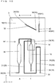
- Fig. 6 and Fig. 7 schematically illustrate the second flow path device 3.
- Fig. 6 is a plan view of the second flow path device 3 when seen from an upper surface transparently.
- Fig. 7 is an enlarged view of a broken line section illustrated in Fig. 6 .
- An A-A line in Fig. 6 is the same as the A-A line in Fig. 1 .
- Part of the planar part 26 connected to at least the vertical part 25 may have a width larger than the vertical part 25. As a result, the retention of the sample can be reduced in a connection part between the planar part 26 and the vertical part 25.
- the planar part 26 may further include a first planar part 27 connected to the vertical part 25 and a second planar part 28 connected to the first planar part 27 and having a width larger than the first planar part 27.
- a width of the first planar part 27 may be equal to or larger than 0.5 mm and equal to or smaller than 3 mm, for example.
- a width of the second planar part 28 may be equal to or larger than 1 mm and equal to or smaller than 5 mm, for example.
- a width of the second planar part 28 may be twice or more and ten times or less than the first planar part 27, for example.
- a connection part between the first planar part 27 and the second planar part 28 is gradually widened.
- the second planar part 28 may have a height larger than the first planar part 27. As a result, the first particles P1 can be easily diffused.
- a height of the first planar part 27 may be equal to or larger than 0.2 mm and equal to or smaller than 1 mm, for example.
- the height of the second planar part 28 may be equal to or larger than 1 mm and equal to or smaller than 5 mm, for example.
- the second flow path device 3 may further include, in addition to the second flow path 16, a third flow path 29 connected to the second flow path 16.
- the third flow path 29 may be connected to the planar part 26 of the second flow path 16.
- the third flow path 29 has a function of sweeping away the sample reaching the planar part 26 by flowing gas, for example. As a result, the retention of the sample in the second flow path 16 can be reduced.
- the third flow path 29 is located to be connected to the connection part between the vertical part 25 and the planar part 26 in the second flow path 16.
- the third flow path 29 is connected to the second flow path 16 as described above.
- the other end of the third flow path 29 serves as a third opening 30 located in the pair of second surfaces 17.
- the third flow path 29 includes a third opening 30 located in one of the pair of second surfaces 17 (in the present disclosure, the second upper surface 19).
- the third opening 30 is an opening through which an extrusion fluid for sweeping away the sample is flowed in.
- At least part of the third flow path 29 connected to the second flow path 16 may extend along an extension direction of the planar part 26 of the second flow path 16 as illustrated in Fig. 7 .
- At least part of the third flow path 29 connected to the second flow path 16 may have the same shape as at least part of the second flow path 16 connected to the third flow path 29.
- the third flow path 29 may include a plurality of extension parts 31 each extending in one direction and arranged in a direction intersecting with one direction.
- the third flow path 29 includes the extension parts 31, thereby being able to reduce the sample flowing back from the second flow path 16 and leaked from the third opening 30.
- the first sample flow inlet (first flow inlet) 12 of the first opening 9 may be located in a surface (the first lower surface 11 in the present disclosure) similar to that of the first sample flow outlet (first flow outlet) 13 of the first opening 9. In this case, the sample flows into the first flow path device 2 from below. As a result, the second particles P2 can be sunk when a specific gravity of the second particles P2 is larger than that of the first particles PI, thus the particles can be separated easily.
- the second flow path device 3 may further include a fourth flow path 32 different from the second flow path 16 and the third flow path 29 as illustrated in Fig. 6 .
- the fourth flow path 32 may include a plurality of fourth openings 33 located in the pair of second surfaces 17.
- the fourth flow path 32 can function as a flow path in which the sample before the microparticles are separated flows. As a result, the sample is flowed into the second flow path device 3 before flowed into the first flow path device 2, thus a foreign material and the like which have been mixed into the sample and the like to be injected can be previously reduced before flowed into a separation flow path.
- the plurality of fourth openings 33 include a fourth flow inlet 34 and a fourth flow outlet 35.
- the fourth flow inlet 34 is an opening through which the sample flows into the fourth flow path 32.
- the fourth flow outlet 35 is an opening through which the sample flows from the fourth flow path 32.
- the fourth flow inlet 34 is exposed outside, and the fourth flow outlet 35 is connected to the first sample flow inlet (first flow inlet) 12 of the first flow path device 2.
- the fourth flow inlet 34 and the fourth flow outlet 35 may be located in the second upper surface 19.
- the above configuration has a significant effect that an operation such as an external connection can be performed from above.
- the fourth flow inlet 34 is located in the same surface as that of the second sample flow outlet 24.
- the fourth flow outlet 35 is located in the same surface as that of the second sample flow outlet 24.
- the fourth flow inlet 34 is located in the same surface as that of the third opening 30.
- the second flow path device 3 may further include a fifth flow path 36 different from the second flow path 16, the third flow path 29, and the fourth flow path 32 as illustrated in Fig. 6 .
- the second flow path 16 is a flow path for flowing the specific microparticles separated and recovered in the first flow path device 2 as described above.
- This fifth flow path 36 can function as a flow path for correction.
- the fifth flow path 36 can flow a sample for correction different from the specific microparticles separated and recovered in the first flow path device 2.
- the fifth flow path 36 includes a plurality of fifth openings 37 located in the pair of second surfaces 17.
- the fifth openings 37 include a fifth flow inlet 38 and a fifth flow outlet 39.
- the fifth flow inlet 38 is an opening through which a fluid for correction flows into the fifth flow path 36.
- the fifth flow outlet 39 is an opening through which a fluid for correction flows from the fifth flow path 36.
- the fifth flow inlet 38 of the plurality of fifth openings 37 is located in the same surface as that of the third opening 30. As a result, an operation of introducing and exhausting the fluid can be performed on the same surface from above.
- the fifth flow outlet 39 is located in the second lower surface 20.
- the second flow path device 3 may further include a sixth flow path 40 different from the second flow path 16, the third flow path 29, the fourth flow path 32, and the fifth flow path 36.
- the sixth flow path 40 includes a plurality of sixth openings 41 located in the pair of second surfaces 17.
- the plurality of sixth openings 41 include a sixth flow inlet 42 and a sixth flow outlet 43.
- the sixth flow inlet 42 is an opening through which a fluid of a pressing flow flows into the sixth flow path 40.
- the sixth flow outlet 43 is an opening through which a fluid of a pressing flow flows from the sixth flow path 40.
- the sixth flow inlet 42 is exposed outside, and the sixth flow outlet 43 is connected to the first pressing flow inlet 15 of the first flow path device 2.
- the third flow path 29, the fourth flow path 32, and the fifth flow path 36 can be formed in the manner similar to the second flow path 16.
- the first flow path device 2 is located on the second upper surface 19 of the second flow path device 3 as described above.
- a sheet member 44 may intervene between the first lower surface 11 of the first flow path device 2 and the second upper surface 19 of the second flow path device 3.
- the inspection flow path device 1 may include the sheet member 44 located between the first flow path device 2 and the second flow path device 3.
- the sheet member 44 has a function as an intermediate layer for bonding hardly-adhesive materials.
- the sheet member 44 may be formed of a material such as silicone or PDMS, for example.
- the inspection flow path device 1 includes the sheet member 44, thereby being able to absorb a waviness of a surface of a bonding surface.
- the sheet member 44 includes a plurality of through holes 45.
- the plurality of through holes 45 preferably correspond to the plurality of first openings 9. As a result, the fluid flows between the first flow path device 2 and the second flow path device 3 via the through holes 45.
- the first flow path device 2 and the second flow path device 3 in the present disclosure are connected via an adhesive agent applied to an upper surface and lower surface of the sheet member 44. It is sufficient that the adhesive agent is a photo-curable resin hardened by ultraviolet or a thermoplastic resin, for example.
- Fig. 8 and Fig. 9 schematically illustrate an inspection apparatus 47.
- Fig. 8 is a drawing of the inspection apparatus 47 with the same viewpoint as that in Fig. 2 , and is a cross-sectional view.
- Fig. 9 illustrates a block diagram of a whole image of the inspection apparatus 47.
- the inspection apparatus 47 includes the inspection flow path device 1 and an optical sensor 48.
- the optical sensor 48 includes a light-emitting element 49 and a light receiving element 50.
- the inspection flow path device 1 can separate the required microparticles (the first particles PI) from the sample.
- the second flow path 16 is irradiated with light from the light-emitting element 49 of the optical sensor 48 to irradiate the microparticles flowing to the second flow path 16 of the inspection flow path device 1 with light, and the light receiving element 50 of the optical sensor 48 receives the light passing through the second flow path 16, thus the microparticles can be measured.
- the light passing through the second flow path 16 is diffused or absorbed, for example, by the microparticles (the first particles PI) in the sample, thus the light intensity decreases.
- a standard curve indicating a relationship between the sample including the particles, the number of which is already known, and an attenuation amount of the light is previously prepared and the attenuation amount of the light in the inspection apparatus 47 is checked against the standard curve, thus the microparticles in the sample can be measured.
- the light-emitting element 49 may be a light emitting diode (LED), for example.
- the light receiving element 50 may be a photo diode (PD), for example.
- the light receiving element 50 includes a semiconductor substrate including a region of one conductivity type and a region of the other conductivity type on an upper surface, for example, and the light-emitting element 49 includes a plurality of semiconductor layers formed on the semiconductor substrate described above.
- a mirror member 51 is located on the second upper surface 19 of the second flow path device 3 in the inspection flow path device 1 in the present disclosure.
- the light-emitting element 49 and the light receiving element 50 of the optical sensor 48 in the present disclosure are located on a side of the second lower surface 20 of the second flow path device 3. Accordingly, the light receiving element 50 of the optical sensor 48 can receive the light passing through the second flow path 16 and reflected from the mirror member 51.
- the mirror member 51 may be formed of a material such as aluminum or gold, for example.
- the mirror member 51 can be formed by an evaporation method, a sputtering method or the like, for example.
- the inspection apparatus 47 further includes a first supply unit 52 supplying the sample, a second supply unit 53 supplying the fluid of the pressing flow, a third supply unit 54 supplying the extrusion fluid, and a fourth supply unit 55 supplying the correction fluid, all of which are connected to the inspection flow path device 1.
- the first supply unit 52 is connected to the fourth flow inlet 34.
- the second supply unit 53 is connected to the sixth flow inlet 42.
- the third supply unit 54 is connected to the third opening 30.
- the fourth supply unit 55 is connected to the fifth flow inlet 38.
- the inspection apparatus 47 includes a controller, and the controller controls the first supply unit 52, the second supply unit 53, the third supply unit 54, the fourth supply unit 55, and the optical sensor 48.
- one end of the fifth flow path 36 includes the fifth flow outlet 39, however, as illustrated in Fig. 10 and Fig. 11 , one end of the fifth flow path 36 may be connected to the second flow path 16.
- the fluid in the fifth flow path 36 can be injected into the second flow path 16, thus the above configuration has a significant effect that a concentration of white blood cells in the second flow path 16 can be reduced.
- Fig. 10 and Fig. 11 are illustrated with the viewpoint similar to that in Fig. 6 and Fig. 7 .
- the fifth flow path 36 may function as the sixth flow path 40. That is to say, the fifth flow path 36 and the sixth flow path 40 may constitute one flow path to be connected to the first flow path 4 (the first pressing flow inlet 15).
- the second flow path device 3 may further include a convex portion 46 located on the second upper surface 19.
- the convex portion 46 may be inserted into the plurality of through holes 45.
- the adhesive agent is not necessary if the connection of the first flow path device 2 and the second flow path device 3 can be secured only with the convex portion 46.
- the second flow path 16 and the second opening 18 may be located in the convex portion 46.
- Fig. 12 is illustrated with the same viewpoint as that in Fig. 5 .
- the first flow path device 2 and second flow path device 3 may be directed connected to each other.
- the connection can be achieved by applying a silane coupling agent to at least one of the first lower surface 11 of the first flow path device 2 or the second upper surface 19 of the second flow path device 3.
- the first flow path 4 is formed by bonding the two substrates, however, the sheet member 44 may be used as one of the two substrates. That is to say, the first flow path 4 may be formed of one substrate and the sheet member 44.
Landscapes
- Chemical & Material Sciences (AREA)
- Health & Medical Sciences (AREA)
- General Health & Medical Sciences (AREA)
- Dispersion Chemistry (AREA)
- Physics & Mathematics (AREA)
- Analytical Chemistry (AREA)
- Chemical Kinetics & Catalysis (AREA)
- General Physics & Mathematics (AREA)
- Biochemistry (AREA)
- Immunology (AREA)
- Pathology (AREA)
- Life Sciences & Earth Sciences (AREA)
- Fluid Mechanics (AREA)
- Hematology (AREA)
- Clinical Laboratory Science (AREA)
- Optical Measuring Cells (AREA)
- Automatic Analysis And Handling Materials Therefor (AREA)
- Separation Of Solids By Using Liquids Or Pneumatic Power (AREA)
- Physical Or Chemical Processes And Apparatus (AREA)
Abstract
Description
- The present disclosure relates to an inspection flow path device and an inspection apparatus.
- A separation and recovery of microparticles are conventionally known (refer to Japanese Patent Application Laid-Open No.
2012-76016 - Conventionally, the separation and recovery of the microparticles and the measurement of the microparticles are separately performed in performing an inspection on the microparticles. In contrast, if the process from the separation to the measurement of the microparticles can be continuously performed, a work efficiency of the inspection can be improved.
- An inspection flow path device according to the present disclosure comprises a first flow path device and a second flow path device connected to the first flow path device. The first flow path device has a plate-like shape and includes a pair of first surfaces located opposite to each other in a thickness direction and a first flow path located inside and including a first opening located in the first surface and a branch flow path. The second flow path device has a plate-like shape and translucency and includes a pair of second surfaces located opposite to each other in a thickness direction and a second flow path located inside and including a second opening located in the second surface. One of the pair of first surfaces of the first flow path device is located to face one of the pair of second surfaces of the second flow path device, and the first opening and the second opening facing each other are connected to each other.
- An inspection apparatus according to the present disclosure includes the inspection flow path device described above and an optical sensor irradiating the second flow path of the second flow path device in the inspection flow path device with light and receiving light passing through the second flow path.
- According to the inspection flow path device and the inspection apparatus in the present disclosure, the work efficiency can be improved.
-
- [
Fig. 1 ] A top view illustrating an example of an inspection flow path device according to an embodiment of the present invention. - [
Fig. 2 ] A cross-sectional view illustrating an example of the inspection flow path device according to the embodiment of the present invention. - [
Fig. 3 ] A top view illustrating part of an example of the inspection flow path device according to the embodiment of the present invention. - [
Fig. 4 ] A top view illustrating part of an example of the inspection flow path device according to the embodiment of the present invention. - [
Fig. 5 ] A cross-sectional view illustrating an example of the inspection flow path device according to the embodiment of the present invention. - [
Fig. 6 ] A top view illustrating part of an example of the inspection flow path device according to the embodiment of the present invention. - [
Fig. 7 ] A top view illustrating part of an example of the inspection flow path device according to the embodiment of the present invention. - [
Fig. 8 ] A cross-sectional view illustrating an example of an inspection apparatus according to the embodiment of the present invention. - [
Fig. 9 ] A block diagram schematically illustrating a configuration of an example of the inspection apparatus according to the embodiment of the present invention. - [
Fig. 10 ] A plan view illustrating an example of an inspection flow path device according to the other embodiment of the present invention. - [
Fig. 11 ] A plan view illustrating an example of an inspection flow path device according to the other embodiment of the present invention. - [
Fig. 12 ] A cross-sectional view illustrating an example of an inspection flow path device according to the other embodiment of the present invention. - Examples of an inspection flow path device and an inspection apparatus according to embodiments of the present invention are described with reference to the drawings. In the present disclosure, a rectangular coordinate system (X, Y, Z) is defined for descriptive purposes to define a positive side in a Z axis direction as an upper side, however, in the present invention, any direction may be the upper side or a lower side. The following contents illustrate embodiments of the present invention, and the present invention is not limited to these embodiments.
-
Fig. 1 andFig. 2 schematically illustrate an inspectionflow path device 1.Fig. 1 is a top view of the inspectionflow path device 1, andFig. 2 is a cross-sectional view of the inspectionflow path device 1 cut along an A-A line inFig. 1 . - When a fluid (a sample) to be inspected is flowed in the inspection
flow path device 1, the inspectionflow path device 1 can separate and recovery a specific component (microparticles) in the sample, and measure the recovered specific component (microparticles). For example, the inspectionflow path device 1 can separate and recover white blood cells (leukocyte) from blood, and measure the number of white blood cells included in the blood. The inspectionflow path device 1 includes a firstflow path device 2 and a secondflow path device 3 connected to the firstflow path device 2. -
Fig. 3 schematically illustrates the firstflow path device 2.Fig. 3 is a plan view of the firstflow path device 2 when seen from an upper surface transparently. - The first
flow path device 2 can separate and recovery microparticles in a fluid (sample). The firstflow path device 2 includes afirst flow path 4. Thefirst flow path 4 includes a main flow path (first main flow path) 5 and a branch flow path (first branch flow path) 6 branching from the firstmain flow path 5. In the firstflow path device 2 in the present disclosure, the fluid flowing in the firstflow path device 2 flows into the firstmain flow path 5, and only microparticles (second particles) different from the specific microparticles (first particles) flow from the firstmain flow path 5 into the firstbranch flow path 6, thus the specific microparticles (first particles) can be separated. When the microparticles (second particles) different from the specific microparticles (first particles) flow into the firstbranch flow path 6, the firstflow path device 1 can also separate the different microparticles (second particles). - The first
branch flow path 6 is designed so that only the second particles are branched and flow therein, however, only the second particles are not necessarily branched. That is to say, microparticles different from the second particles may flow into the firstbranch flow path 6 in some cases. -
Fig. 4 schematically illustrates a process of separating the first particles and the second particles.Fig. 4 is an enlarged view of a broken line section inFig. 3 . Herein, a large circle inFig. 4 indicates the first particle PI and a small circle indicates the second particle P2. A thick arrow along the X axis direction indicates a main stream and a thin arrow along the Y axis direction indicates a "pressing flow" described hereinafter. A hatched region inFig. 4 indicates a "lead-in flow" described hereinafter. - The
first flow path 4 in the present disclosure includes one firstmain flow path 5 and the plurality of firstbranch flow path 6 connected to one side of the one firstmain flow path 5. In the firstflow path device 2, a sectional area and length of each of the firstmain flow path 5 and the firstbranch flow path 6, a flow rate of the sample and the like are adjusted, thus the "lead-in flow", which flows from the firstmain flow path 5 into the firstbranch flow path 6 can be generated in the firstmain flow path 5. The firstflow path device 2 generates the pressing flow, which can press the sample flowing in the firstmain flow path 5 against a side of the firstbranch flow path 6, in thefirst flow path 4. As a result, as illustrated inFig. 4 , a width of the lead-in flow is set to larger than a barycentric position of the specific microparticle (the first particle PI) flowing in the sample and smaller than a barycentric position of the other microparticle (the second particle P2), thus the other microparticles (the second particle P2) can be lead in the firstbranch flow path 6. At this time, a width of the firstbranch flow path 6 is set to smaller than a size of the specific microparticle (the first particle PI) flowing in the sample and larger than a size of the other microparticle (the second particle P2), thus the other microparticles (the second particle P2) can be lead in the firstbranch flow path 6. - The first
flow path device 2 in the present disclosure is particularly intended to separate red blood cells (erythrocyte) and white blood cells (leukocyte) in blood. A barycentric position of the red blood cell in the blood is located 2 to 2.5 µm from an edge thereof, for example, and the size of the red blood cell is 6 to 8 µm, for example. A barycentric position of the white blood cell is located 5 to 10 µm from an edge thereof, for example, and the size of the white blood cell is 10 to 30 µm, for example. In this case, the firstmain flow path 5 may have the sectional area ranging from 300 µm2 to 1000 µm2 and the length ranging from 0.5 mm to 20 mm, for example. The firstbranch flow path 6 may have the sectional area ranging from 100 µm2 to 500 µm2 and the length ranging from 3 mm to 25 mm, for example. The flow rate in thefirst flow path 4 may be equal to or larger than 0.2 m/s and equal to or smaller than 5 m/s, for example. As a result, the width of the lead-in flow can be set equal to or larger than 2 µm and equal to or smaller than 15 µm, for example, thus the red blood cell and the white blood cell in the blood can be separated. - The
first flow path 4 further includes a firstrecovery flow path 7 connected to the firstmain flow path 5, and can recovery the first particles PI. In thefirst flow path 4 in the present disclosure, the first particles P1 can be recovered in the firstrecovery flow path 7 using the pressing flow. - The
first flow path 4 may include a first disposal flow path 7' connected to the plurality of firstbranch flow paths 6. The first disposal flow path 7' may recover or dispose of the separated second particles P2. When the second particles P2 are recovered by the plurality of firstbranch flow paths 6, one first disposal flow path 7' to which the plurality of firstbranch flow paths 6 are connected functions as a flow path for recovering the second particles P2. The fluid flowing to an end of the firstmain flow path 5 may be disposed of. - The first
flow path device 2 is a plate-like member. Thefirst flow path 4 is located inside the plate-like member. The firstflow path device 2 includes a pair offirst surfaces 8 located opposite to each other in a thickness direction (the Z axis direction). Thefirst flow path 4 is opened in the pair offirst surfaces 8. In other words, thefirst flow path 4 includes a plurality offirst openings 9 located in the pair offirst surfaces 8. - In the present disclosure, one of the pair of
first surfaces 8 is defined as a firstupper surface 10 and the other one thereof is defined as a firstlower surface 11 for descriptive purposes. In the pair offirst surfaces 8, the firstupper surface 10 is a surface located on a positive side of the Z axis and the firstlower surface 11 is a surface located on a negative side of the Z axis. In the present disclosure, at least one of the plurality offirst openings 9 is located in the firstlower surface 11. - The plurality of
first openings 9 include a first flow inlet (first sample flow inlet) 12 through which the sample flows into at least the firstmain flow path 5, a first flow outlet (a first sample flow outlet) 13 through which the first particles P1 are recovered from the firstrecovery flow path 7, and at least one firstdisposal flow outlet 14 through which constituents in which the first particles P1 are removed from the sample are recovered. Included in the present disclosure is a firstpressing flow inlet 15 through which the fluid of the pressing flow for pressing the sample against the firstbranch flow path 6 side flows. In the present disclosure, the firstdisposal flow outlet 14 is connected to the firstmain flow path 5 and the first disposal flow path 7'. The fluid flowing out through the firstdisposal flow outlet 14 is recovered through a through hole 14' formed in the secondflow path device 3. - A planar shape of the first
flow path device 2 in the present disclosure is a rectangular shape. Each of thefirst surfaces 8 in the present disclosure is a flat surface. A planar shape of the firstflow path device 2 is not limited to the rectangular shape. Each of thefirst surfaces 8 in the present disclosure is not limited to the flat surface. In thefirst surfaces 8, shapes of the firstupper surface 10 and the firstlower surface 11 may be different from each other. - The first
flow path device 2 may be formed of a material of polydimethylsiloxane (PDMS) or acrylic (PMMA), for example. A thickness of the firstflow path device 2 may be equal to or larger than 1 mm and equal to or smaller than 5 mm, for example. The planar shape of the firstflow path device 2 may have a short side with a length equal to or larger than 10 mm and equal to or smaller than 30 mm and a long side with a length equal to or larger than 10 mm and equal to or smaller than 50 mm, for example. The firstflow path device 2 can be formed by preparing two substrates, forming a groove in one of the two substrates, and attaching the two substrates to each other to cover the groove, for example. - The second
flow path device 3 is a flow path for measuring the specific microparticles separated and recovered in the firstflow path device 2. As illustrated inFig. 2 , the secondflow path device 3 includes asecond flow path 16 connected to thefirst flow path 4 in the firstflow path device 2. The secondflow path device 3 has translucency. As a result, the secondflow path device 3 can flow the specific microparticles separated and recovered in the firstflow path device 2 to thesecond flow path 16 and measure the specific microparticles using an optical sensor described hereinafter. Specifically, the secondflow path device 3 measures intensity of light passing through thesecond flow path 16, thereby measuring the specific microparticles. - The second
flow path device 3 is a plate-like member. Thesecond flow path 16 is located inside the plate-like member. The secondflow path device 3 includes a pair ofsecond surfaces 17 located opposite to each other in a thickness direction (the Z axis direction). Thesecond flow path 16 is opened in the pair of second surfaces 17. In other words, thesecond flow path 16 includes a plurality ofsecond openings 18 located in the pair of second surfaces 17. - In the present disclosure, one of the pair of
second surfaces 17 is defined as a secondupper surface 19 and the other one thereof is defined as a secondlower surface 20 for descriptive purposes. In the pair ofsecond surfaces 17, the secondupper surface 19 is a surface located on a positive side of the Z axis and the secondlower surface 20 is a surface located on a negative side of the Z axis. - A planar shape of the second
flow path device 3 in the present disclosure is a rectangular shape. Each of thesecond surfaces 17 in the present disclosure is a flat surface. A planar shape of the secondflow path device 3 is not limited to the rectangular shape. Each of thesecond surfaces 17 in the present disclosure is not limited to the flat surface. In thesecond surfaces 17, shapes of the secondupper surface 19 and the secondlower surface 20 may be different from each other. - The second
flow path device 3 may be formed of acrylic (PMMA) or cycloolefin polymer (COP), for example. A thickness of the secondflow path device 3 may be equal to or larger than 0.5 mm and equal to or smaller than 5 mm, for example. The planar shape of the secondflow path device 3 may have a short side with a length equal to or larger than 10 mm and equal to or smaller than 30 mm and a long side with a length equal to or larger than 20 mm and equal to or smaller than 50 mm, for example. The secondflow path device 3 can be formed by preparing two substrates, forming a groove in one of the two substrates, and attaching the two substrates to each other to cover the groove, for example. -
Fig. 5 schematically illustrates the firstflow path device 2 and the secondflow path device 3.Fig. 5 is an enlarged view of a broken line section inFig. 2 . - In the second
flow path device 3 in the present disclosure, at least one of the plurality ofsecond openings 18 is located in the secondupper surface 19. The firstflow path device 2 is located on the secondupper surface 19 via the firstlower surface 11, and thefirst opening 9 located in the firstlower surface 11 and thesecond opening 18 located in the secondupper surface 19 are connected to each other. Accordingly, in the inspectionflow path device 1 in the present disclosure, the firstflow path device 2 is directly connected to the secondflow path device 3, and the process from the separation and recovery to the measurement of the specific microparticles in the sample can be continuously performed, thus a work efficiency can be improved. The plate-like firstflow path device 2 and secondflow path device 3 are located to be stacked in the thickness direction, thus the inspectionflow path device 1 can be minimized. - The second
upper surface 19 of the secondflow path device 3 in the present disclosure includes afirst region 21 and asecond region 22. In a plan view, thesecond flow path 16 in the secondflow path device 3 is located to extend from thefirst region 21 to thesecond region 22, and in a transparent plan view, thesecond flow path 16 overlaps with thefirst region 21 and thesecond region 22. The firstflow path device 2 is located only on thefirst region 21 in the secondflow path device 3. As a result, thesecond flow path 16 is exposed to thesecond region 22, thus thesecond region 22 can be used as a measurement region. - In the inspection
flow path device 1, a member which can reflect light may be located on thesecond region 22 as described hereinafter. - The first
flow path device 2 may be formed of a material different from that of the secondflow path device 3. In the present disclosure, for example, the firstflow path device 2 is formed of PDMS and the like, and the secondflow path device 3 is formed of COP and the like. - As is the case in the present disclosure, the first
flow path device 2 may be located on an upper side of the secondflow path device 3. Specifically, the firstflow path device 2 may be located on the secondupper surface 19 of the secondflow path device 3. As a result, the specific microparticles in the sample separated and recovered in the firstflow path device 2 can be flowed into the secondflow path device 3 also using gravity, and a retention of the recovered microparticles midway through the flow path can be reduced. - The present invention does not exclude an embodiment in which the first
flow path device 2 is located on the secondlower surface 20 of the secondflow path device 3. - The plurality of
second openings 18 include a secondsample flow inlet 23 through which the sample flows into thesecond flow path 16 and a secondsample flow outlet 24 through which the sample is recovered from thesecond flow path 16. The secondsample flow inlet 23 is located in the secondupper surface 19, and is connected to the firstsample flow outlet 13 in the firstflow path device 2. The secondsample flow outlet 24 is located in the secondlower surface 20. As a result, by using the gravity, the sample can be easily flowed from the firstflow path device 2 through the secondsample flow inlet 23 and the sample can be easily recovered in the secondsample flow outlet 24. - An opening of the second
sample flow outlet 24 may be larger than an opening of the firstsample flow outlet 13 as illustrated inFig. 5 . As a result, the retention of the sample can be reduced in a connection part between the firstflow path device 2 and the secondflow path device 3. A size of the secondsample flow outlet 24 may be equal to or larger than 1 mm and equal to or smaller than 3 mm, for example. A size of the firstsample flow outlet 13 may be equal to or larger than 1 mm and equal to or smaller than 3 mm, for example. - The
second flow path 16 includes avertical part 25 connected to the second sample flow inlet 23 (the second opening 18) and extending in the thickness direction and aplanar part 26 connected to thevertical part 25 and extending along a planar surface direction. Thesecond flow path 16 includes thevertical part 25, thereby being able to reduce the retention of the sample including the specific microparticles in the connection part between thesecond flow path 16 and thefirst flow path 4. Thesecond flow path 16 includes theplanar part 26, thereby being able to retain the sample including the specific microparticles, thus a stable measurement can be achieved. - A width of the
vertical part 25 may be equal to or larger than 0.5 mm and equal to or smaller than 2 mm, for example, and a width of theplanar part 26 may be equal to or larger than 1 mm and equal to or smaller than 6 mm, for example. A length of thevertical part 25 may be equal to or larger than 0.5 mm and equal to or smaller than 1 mm, for example, and a height of theplanar part 26 may be equal to or larger than 0.5 mm and equal to or smaller than 2 mm, for example. -
Fig. 6 andFig. 7 schematically illustrate the secondflow path device 3.Fig. 6 is a plan view of the secondflow path device 3 when seen from an upper surface transparently.Fig. 7 is an enlarged view of a broken line section illustrated inFig. 6 . An A-A line inFig. 6 is the same as the A-A line inFig. 1 . - Part of the
planar part 26 connected to at least thevertical part 25 may have a width larger than thevertical part 25. As a result, the retention of the sample can be reduced in a connection part between theplanar part 26 and thevertical part 25. - The
planar part 26 may further include a firstplanar part 27 connected to thevertical part 25 and a secondplanar part 28 connected to the firstplanar part 27 and having a width larger than the firstplanar part 27. As a result, the first particles P1 can be easily diffused. A width of the firstplanar part 27 may be equal to or larger than 0.5 mm and equal to or smaller than 3 mm, for example. A width of the secondplanar part 28 may be equal to or larger than 1 mm and equal to or smaller than 5 mm, for example. A width of the secondplanar part 28 may be twice or more and ten times or less than the firstplanar part 27, for example. In the present disclosure, a connection part between the firstplanar part 27 and the secondplanar part 28 is gradually widened. - The second
planar part 28 may have a height larger than the firstplanar part 27. As a result, the first particles P1 can be easily diffused. A height of the firstplanar part 27 may be equal to or larger than 0.2 mm and equal to or smaller than 1 mm, for example. The height of the secondplanar part 28 may be equal to or larger than 1 mm and equal to or smaller than 5 mm, for example. - The second
flow path device 3 may further include, in addition to thesecond flow path 16, athird flow path 29 connected to thesecond flow path 16. Thethird flow path 29 may be connected to theplanar part 26 of thesecond flow path 16. Thethird flow path 29 has a function of sweeping away the sample reaching theplanar part 26 by flowing gas, for example. As a result, the retention of the sample in thesecond flow path 16 can be reduced. - In the second
flow path device 3 in the present disclosure, as illustrated inFig. 5 andFig. 7 , thethird flow path 29 is located to be connected to the connection part between thevertical part 25 and theplanar part 26 in thesecond flow path 16. - One end of the
third flow path 29 is connected to thesecond flow path 16 as described above. The other end of thethird flow path 29 serves as athird opening 30 located in the pair of second surfaces 17. In other words, thethird flow path 29 includes athird opening 30 located in one of the pair of second surfaces 17 (in the present disclosure, the second upper surface 19). Thethird opening 30 is an opening through which an extrusion fluid for sweeping away the sample is flowed in. - At least part of the
third flow path 29 connected to thesecond flow path 16 may extend along an extension direction of theplanar part 26 of thesecond flow path 16 as illustrated inFig. 7 . - At least part of the
third flow path 29 connected to thesecond flow path 16 may have the same shape as at least part of thesecond flow path 16 connected to thethird flow path 29. As a result, a level difference occurring between thesecond flow path 16 and thethird flow path 29 and the retention of the sample in the level difference can be reduced. - The
third flow path 29 may include a plurality ofextension parts 31 each extending in one direction and arranged in a direction intersecting with one direction. Thethird flow path 29 includes theextension parts 31, thereby being able to reduce the sample flowing back from thesecond flow path 16 and leaked from thethird opening 30. - The first sample flow inlet (first flow inlet) 12 of the
first opening 9 may be located in a surface (the firstlower surface 11 in the present disclosure) similar to that of the first sample flow outlet (first flow outlet) 13 of thefirst opening 9. In this case, the sample flows into the firstflow path device 2 from below. As a result, the second particles P2 can be sunk when a specific gravity of the second particles P2 is larger than that of the first particles PI, thus the particles can be separated easily. - The second
flow path device 3 may further include afourth flow path 32 different from thesecond flow path 16 and thethird flow path 29 as illustrated inFig. 6 . Thefourth flow path 32 may include a plurality offourth openings 33 located in the pair of second surfaces 17. Thefourth flow path 32 can function as a flow path in which the sample before the microparticles are separated flows. As a result, the sample is flowed into the secondflow path device 3 before flowed into the firstflow path device 2, thus a foreign material and the like which have been mixed into the sample and the like to be injected can be previously reduced before flowed into a separation flow path. - The plurality of
fourth openings 33 include afourth flow inlet 34 and afourth flow outlet 35. Thefourth flow inlet 34 is an opening through which the sample flows into thefourth flow path 32. Thefourth flow outlet 35 is an opening through which the sample flows from thefourth flow path 32. Thefourth flow inlet 34 is exposed outside, and thefourth flow outlet 35 is connected to the first sample flow inlet (first flow inlet) 12 of the firstflow path device 2. - The
fourth flow inlet 34 and thefourth flow outlet 35 may be located in the secondupper surface 19. The above configuration has a significant effect that an operation such as an external connection can be performed from above. In the present disclosure, thefourth flow inlet 34 is located in the same surface as that of the secondsample flow outlet 24. In the present disclosure, thefourth flow outlet 35 is located in the same surface as that of the secondsample flow outlet 24. Thefourth flow inlet 34 is located in the same surface as that of thethird opening 30. - The second
flow path device 3 may further include afifth flow path 36 different from thesecond flow path 16, thethird flow path 29, and thefourth flow path 32 as illustrated inFig. 6 . Thesecond flow path 16 is a flow path for flowing the specific microparticles separated and recovered in the firstflow path device 2 as described above. Thisfifth flow path 36 can function as a flow path for correction. Thefifth flow path 36 can flow a sample for correction different from the specific microparticles separated and recovered in the firstflow path device 2. As a result, it is possible to measure thesecond flow path 16 and thefifth flow path 36 in sequence every time the specific microparticles are measured to estimate the number of specific microparticles in accordance with a difference of light intensity of theflow paths - The
fifth flow path 36 includes a plurality offifth openings 37 located in the pair of second surfaces 17. Thefifth openings 37 include afifth flow inlet 38 and afifth flow outlet 39. Thefifth flow inlet 38 is an opening through which a fluid for correction flows into thefifth flow path 36. Thefifth flow outlet 39 is an opening through which a fluid for correction flows from thefifth flow path 36. - The
fifth flow inlet 38 of the plurality offifth openings 37 is located in the same surface as that of thethird opening 30. As a result, an operation of introducing and exhausting the fluid can be performed on the same surface from above. Thefifth flow outlet 39 is located in the secondlower surface 20. - The second
flow path device 3 may further include asixth flow path 40 different from thesecond flow path 16, thethird flow path 29, thefourth flow path 32, and thefifth flow path 36. Thesixth flow path 40 includes a plurality ofsixth openings 41 located in the pair of second surfaces 17. The plurality ofsixth openings 41 include asixth flow inlet 42 and asixth flow outlet 43. Thesixth flow inlet 42 is an opening through which a fluid of a pressing flow flows into thesixth flow path 40. Thesixth flow outlet 43 is an opening through which a fluid of a pressing flow flows from thesixth flow path 40. Thesixth flow inlet 42 is exposed outside, and thesixth flow outlet 43 is connected to the firstpressing flow inlet 15 of the firstflow path device 2. - The
third flow path 29, thefourth flow path 32, and thefifth flow path 36 can be formed in the manner similar to thesecond flow path 16. - The first
flow path device 2 is located on the secondupper surface 19 of the secondflow path device 3 as described above. Herein, asheet member 44 may intervene between the firstlower surface 11 of the firstflow path device 2 and the secondupper surface 19 of the secondflow path device 3. In other words, the inspectionflow path device 1 may include thesheet member 44 located between the firstflow path device 2 and the secondflow path device 3. - The
sheet member 44 has a function as an intermediate layer for bonding hardly-adhesive materials. Thesheet member 44 may be formed of a material such as silicone or PDMS, for example. The inspectionflow path device 1 includes thesheet member 44, thereby being able to absorb a waviness of a surface of a bonding surface. Thesheet member 44 includes a plurality of throughholes 45. The plurality of throughholes 45 preferably correspond to the plurality offirst openings 9. As a result, the fluid flows between the firstflow path device 2 and the secondflow path device 3 via the through holes 45. - The first
flow path device 2 and the secondflow path device 3 in the present disclosure are connected via an adhesive agent applied to an upper surface and lower surface of thesheet member 44. It is sufficient that the adhesive agent is a photo-curable resin hardened by ultraviolet or a thermoplastic resin, for example. - An
inspection apparatus 47 is described next. -
Fig. 8 andFig. 9 schematically illustrate aninspection apparatus 47.Fig. 8 is a drawing of theinspection apparatus 47 with the same viewpoint as that inFig. 2 , and is a cross-sectional view.Fig. 9 illustrates a block diagram of a whole image of theinspection apparatus 47. - The
inspection apparatus 47 includes the inspectionflow path device 1 and anoptical sensor 48. Theoptical sensor 48 includes a light-emittingelement 49 and alight receiving element 50. As a result, firstly, the inspectionflow path device 1 can separate the required microparticles (the first particles PI) from the sample. Then, thesecond flow path 16 is irradiated with light from the light-emittingelement 49 of theoptical sensor 48 to irradiate the microparticles flowing to thesecond flow path 16 of the inspectionflow path device 1 with light, and thelight receiving element 50 of theoptical sensor 48 receives the light passing through thesecond flow path 16, thus the microparticles can be measured. Specifically, the light passing through thesecond flow path 16 is diffused or absorbed, for example, by the microparticles (the first particles PI) in the sample, thus the light intensity decreases. As a result, a standard curve indicating a relationship between the sample including the particles, the number of which is already known, and an attenuation amount of the light is previously prepared and the attenuation amount of the light in theinspection apparatus 47 is checked against the standard curve, thus the microparticles in the sample can be measured. - The light-emitting
element 49 may be a light emitting diode (LED), for example. Thelight receiving element 50 may be a photo diode (PD), for example. Thelight receiving element 50 includes a semiconductor substrate including a region of one conductivity type and a region of the other conductivity type on an upper surface, for example, and the light-emittingelement 49 includes a plurality of semiconductor layers formed on the semiconductor substrate described above. - A
mirror member 51 is located on the secondupper surface 19 of the secondflow path device 3 in the inspectionflow path device 1 in the present disclosure. The light-emittingelement 49 and thelight receiving element 50 of theoptical sensor 48 in the present disclosure are located on a side of the secondlower surface 20 of the secondflow path device 3. Accordingly, thelight receiving element 50 of theoptical sensor 48 can receive the light passing through thesecond flow path 16 and reflected from themirror member 51. Themirror member 51 may be formed of a material such as aluminum or gold, for example. Themirror member 51 can be formed by an evaporation method, a sputtering method or the like, for example. - The
inspection apparatus 47 further includes afirst supply unit 52 supplying the sample, asecond supply unit 53 supplying the fluid of the pressing flow, athird supply unit 54 supplying the extrusion fluid, and afourth supply unit 55 supplying the correction fluid, all of which are connected to the inspectionflow path device 1. Thefirst supply unit 52 is connected to thefourth flow inlet 34. Thesecond supply unit 53 is connected to thesixth flow inlet 42. Thethird supply unit 54 is connected to thethird opening 30. Thefourth supply unit 55 is connected to thefifth flow inlet 38. Theinspection apparatus 47 includes a controller, and the controller controls thefirst supply unit 52, thesecond supply unit 53, thethird supply unit 54, thefourth supply unit 55, and theoptical sensor 48. - The present invention is not limited to the embodiments described above, however, various alternation and modifications, for example, should be possible within the scope of the present invention.
- The above embodiments describe the example that one end of the
fifth flow path 36 includes thefifth flow outlet 39, however, as illustrated inFig. 10 andFig. 11 , one end of thefifth flow path 36 may be connected to thesecond flow path 16. As a result, the fluid in thefifth flow path 36 can be injected into thesecond flow path 16, thus the above configuration has a significant effect that a concentration of white blood cells in thesecond flow path 16 can be reduced.Fig. 10 andFig. 11 are illustrated with the viewpoint similar to that inFig. 6 andFig. 7 . - The above embodiments describe the example of including the
fifth flow path 36 and thesixth flow path 40, however, thefifth flow path 36 may function as thesixth flow path 40. That is to say, thefifth flow path 36 and thesixth flow path 40 may constitute one flow path to be connected to the first flow path 4 (the first pressing flow inlet 15). - The above embodiments describe the example that the first
flow path device 2 and the secondflow path device 3 are bonded via thesheet member 44. However, as illustrated inFig. 12 , the secondflow path device 3 may further include aconvex portion 46 located on the secondupper surface 19. Theconvex portion 46 may be inserted into the plurality of throughholes 45. As a result, the firstflow path device 2 and the secondflow path device 3 can be connected to each other. The adhesive agent is not necessary if the connection of the firstflow path device 2 and the secondflow path device 3 can be secured only with theconvex portion 46. In this case, thesecond flow path 16 and thesecond opening 18 may be located in theconvex portion 46.Fig. 12 is illustrated with the same viewpoint as that inFig. 5 . - The first
flow path device 2 and secondflow path device 3 may be directed connected to each other. In this case, for example, the connection can be achieved by applying a silane coupling agent to at least one of the firstlower surface 11 of the firstflow path device 2 or the secondupper surface 19 of the secondflow path device 3. - The above embodiments describe the example that the
first flow path 4 is formed by bonding the two substrates, however, thesheet member 44 may be used as one of the two substrates. That is to say, thefirst flow path 4 may be formed of one substrate and thesheet member 44. -
- 1
- inspection flow path device
- 2
- first flow path device
- 3
- second flow path device
- 4
- first flow path
- 5
- main flow path (first main flow path)
- 6
- branch flow path (first branch flow path)
- 8
- first surface
- 9
- first opening
- 10
- first upper surface
- 11
- first lower surface
- 16
- second flow path
- 17
- second surface
- 18
- second opening
- 19
- second upper surface
- 20
- second lower surface
- 21
- first region
- 22
- second region
- 25
- vertical part
- 26
- planar part
- 27
- first planar part
- 28
- second planar part
- 29
- third flow path
- 32
- fourth flow path
- 33
- fourth opening
- 34
- fourth flow inlet
- 35
- fourth flow outlet
- 47
- inspection apparatus
- 48
- optical sensor
Claims (17)
- An inspection flow path device, comprising:a first flow path device having a plate-like shape and including a pair of first surfaces located opposite to each other in a thickness direction and a first flow path located inside and including a first opening located in the first surface and a branch flow path; anda second flow path device having a plate-like shape and translucency and including a pair of second surfaces located opposite to each other in a thickness direction and a second flow path located inside and including a second opening located in the second surface; whereinone of the pair of first surfaces of the first flow path device is located on one of the pair of second surfaces of the second flow path device, andthe first opening and the second opening are connected to each other.
- The inspection flow path device according to claim 1, wherein
the second flow path device further includes a first region and a second region located on the one of the pair of first surfaces and overlapping with the second flow path in a transparent plan view, and
the first flow path device is located only on the first region of the second flow path device. - The inspection flow path device according to claim 1 or 2, wherein
a material of the first flow path of the first flow path device is different from a material of the second flow path of the second flow path device. - The inspection flow path device according to any one of claims 1 to 3, wherein
the pair of first surfaces of the first flow path device are made up of a first upper surface and a first lower surface, and
the pair of second surfaces of the second flow path device are made up of a second upper surface and a second lower surface, and
the first lower surface of the first flow path device is located on the second upper surface of the second flow path device. - The inspection flow path device according to any one of claims 1 to 4, wherein
the second flow path in the second flow path device further includes a vertical part connected to the second opening and extending in a thickness direction and a planar part connected to the vertical part and extending along a planar surface direction. - The inspection flow path device according to claim 5, wherein
at least a part of the planar part connected to the vertical part has a width larger than the vertical part. - The inspection flow path device according to claim 5 or 6, wherein
the planar part further includes a first planar part connected to the vertical part and a second planar part connected to the first planar part and having a width larger than the first planar part. - The inspection flow path device according to any one of claims 5 to 7, wherein
the planar part further includes a first planar part connected to the vertical part and a second planar part connected to the first planar part and having a height larger than the first planar part. - The inspection flow path device according to any one of claims 5 to 8, wherein
the second opening has a width larger than the first opening. - The inspection flow path device according to any one of claims 5 to 9, wherein
the second flow path device further includes a third flow path located inside, and
the third flow path is connected to a connection part between the vertical part and the planar part in the second flow path. - The inspection flow path device according to claim 10, wherein
the third flow path connected to the second flow path extends along an extension direction of the planar part of the second flow path. - The inspection flow path device according to claim 10 or 11, wherein
at least a part of the third flow path connected to the second flow path has a shape identical to at least a part of the second flow path connected to the third flow path. - The inspection flow path device according to any one of claims 10 to 12, wherein
the third flow path includes a plurality of planar parts each extending in one direction and arranged in a direction intersecting with the one direction. - The inspection flow path device according to any one of claims 1 to 13, wherein
the first flow path further includes a first flow inlet which is an opening different from a first flow outlet when the first opening is defined as the first flow outlet, and
the first flow outlet and the first flow inlet are located in the one of the pair of first surfaces. - The inspection flow path device according to claim 14, wherein
the second flow path device further includes a fourth flow path including a fourth opening located in a surface of the pair of second surfaces identical to a surface where the second opening is located, and
the fourth opening is connected to the first flow inlet. - The inspection flow path device according to claim 15, wherein
the fourth flow path further includes a fourth flow inlet which is an opening different from a fourth flow outlet when the fourth opening is defined as the fourth flow outlet and exposed outside, and
the fourth flow outlet and the fourth flow outlet are located in the surface of the pair of second surfaces identical to the surface where the second opening is located. - An inspection apparatus, comprising:the inspection flow path device according to any one of claims 1 to 16; andan optical sensor irradiating the second flow path of the second flow path device in the inspection flow path device with light and receiving light passing through the second flow path.
Applications Claiming Priority (2)
| Application Number | Priority Date | Filing Date | Title |
|---|---|---|---|
| JP2018013698 | 2018-01-30 | ||
| PCT/JP2019/002556 WO2019151150A1 (en) | 2018-01-30 | 2019-01-25 | Inspection flow channel device and inspection apparatus |
Publications (2)
| Publication Number | Publication Date |
|---|---|
| EP3748332A1 true EP3748332A1 (en) | 2020-12-09 |
| EP3748332A4 EP3748332A4 (en) | 2021-10-27 |
Family
ID=67479303
Family Applications (1)
| Application Number | Title | Priority Date | Filing Date |
|---|---|---|---|
| EP19748305.0A Withdrawn EP3748332A4 (en) | 2018-01-30 | 2019-01-25 | INSPECTION FLOW DUCT DEVICE AND INSPECTION DEVICE |
Country Status (4)
| Country | Link |
|---|---|
| US (1) | US11351542B2 (en) |
| EP (1) | EP3748332A4 (en) |
| JP (1) | JP6976361B2 (en) |
| WO (1) | WO2019151150A1 (en) |
Cited By (2)
| Publication number | Priority date | Publication date | Assignee | Title |
|---|---|---|---|---|
| EP3933378A4 (en) * | 2019-02-27 | 2022-11-30 | Kyocera Corporation | PARTICLE SEPARATION AND MEASURING DEVICE AND PARTICLE SEPARATION AND MEASURING APPARATUS |
| US12000770B2 (en) | 2019-02-27 | 2024-06-04 | Kyocera Corporation | Particle separating and measuring device and particle separating and measuring apparatus |
Families Citing this family (10)
| Publication number | Priority date | Publication date | Assignee | Title |
|---|---|---|---|---|
| US11255770B2 (en) * | 2018-01-30 | 2022-02-22 | Kyocera Corporation | Measurement apparatus |
| US11740228B2 (en) * | 2018-09-27 | 2023-08-29 | Kyocera Corporation | Particle separating and measuring device, and particle separating and measuring apparatus |
| CN113557423B (en) * | 2019-03-20 | 2024-03-08 | 京瓷株式会社 | Particle flow path plate, particle separation equipment, and particle separation measurement device |
| JP6761153B1 (en) * | 2019-03-20 | 2020-09-23 | 京セラ株式会社 | Particle measurement device and particle separation measurement device and particle separation measurement device |
| CN114641693A (en) | 2019-11-19 | 2022-06-17 | 京瓷株式会社 | Flow channel device, method for manufacturing flow channel device, flow channel device for measurement, and inspection device |
| US12345618B2 (en) | 2020-03-24 | 2025-07-01 | Kyocera Corporation | Flow path device for separating target particles in a fluid |
| US20230144961A1 (en) * | 2020-03-24 | 2023-05-11 | Kyocera Corporation | Flow path device |
| WO2021193283A1 (en) | 2020-03-24 | 2021-09-30 | 京セラ株式会社 | Flow path device |
| JP7589913B2 (en) * | 2020-11-06 | 2024-11-26 | シチズンファインデバイス株式会社 | Detection device |
| CN117980747A (en) | 2021-09-30 | 2024-05-03 | 京瓷株式会社 | Flow path devices and separation processing devices |
Family Cites Families (16)
| Publication number | Priority date | Publication date | Assignee | Title |
|---|---|---|---|---|
| JP2003004752A (en) * | 2001-06-15 | 2003-01-08 | Minolta Co Ltd | Microchip and inspection apparatus using the same |
| JP2003207504A (en) * | 2002-01-15 | 2003-07-25 | Minolta Co Ltd | Chip and filter for cytapheresis |
| JP2005030906A (en) * | 2003-07-11 | 2005-02-03 | Mitsubishi Chemicals Corp | Analysis chip and analysis method |
| US7295306B2 (en) | 2004-04-22 | 2007-11-13 | Kowa Company, Ltd. | Microchip and fluorescent particle counter with microchip |
| JP4528664B2 (en) * | 2004-04-22 | 2010-08-18 | 興和株式会社 | Fluorescent particle counter |
| WO2010144814A2 (en) * | 2009-06-13 | 2010-12-16 | Arryx, Inc. | Particle sorting using fluid streams |
| JP2007175684A (en) * | 2005-12-26 | 2007-07-12 | Minoru Seki | Flow passage structure and method for concentration and classification of fine particle |
| US7976795B2 (en) * | 2006-01-19 | 2011-07-12 | Rheonix, Inc. | Microfluidic systems |
| JP2008244165A (en) | 2007-03-27 | 2008-10-09 | Toshiba Lighting & Technology Corp | Lighting device |
| JP2009178078A (en) * | 2008-01-30 | 2009-08-13 | Hitachi Engineering & Services Co Ltd | Microbiological testing chip and microbiological testing instrument |
| JP5641213B2 (en) | 2010-10-01 | 2014-12-17 | 国立大学法人 千葉大学 | Continuous two-dimensional particle separation apparatus and particle separation method |
| JP2014006085A (en) * | 2012-06-21 | 2014-01-16 | Sharp Corp | Counting chip, counting method, and counting device |
| US9248448B2 (en) * | 2013-04-24 | 2016-02-02 | William Marsh Rice University | Multisample bionanochip platform |
| EP3088076A4 (en) | 2013-12-27 | 2017-08-30 | ASAHI FR R&D Co., Ltd. | Three-dimensional microchemical chip |
| JP6417684B2 (en) * | 2014-03-17 | 2018-11-07 | セイコーエプソン株式会社 | Liquid ejecting head and liquid ejecting apparatus |
| JPWO2017221986A1 (en) * | 2016-06-22 | 2019-05-16 | 京セラ株式会社 | Particle measuring instrument |
-
2019
- 2019-01-25 EP EP19748305.0A patent/EP3748332A4/en not_active Withdrawn
- 2019-01-25 US US16/960,777 patent/US11351542B2/en active Active
- 2019-01-25 JP JP2019569087A patent/JP6976361B2/en active Active
- 2019-01-25 WO PCT/JP2019/002556 patent/WO2019151150A1/en not_active Ceased
Cited By (2)
| Publication number | Priority date | Publication date | Assignee | Title |
|---|---|---|---|---|
| EP3933378A4 (en) * | 2019-02-27 | 2022-11-30 | Kyocera Corporation | PARTICLE SEPARATION AND MEASURING DEVICE AND PARTICLE SEPARATION AND MEASURING APPARATUS |
| US12000770B2 (en) | 2019-02-27 | 2024-06-04 | Kyocera Corporation | Particle separating and measuring device and particle separating and measuring apparatus |
Also Published As
| Publication number | Publication date |
|---|---|
| JP6976361B2 (en) | 2021-12-08 |
| US20200330992A1 (en) | 2020-10-22 |
| WO2019151150A1 (en) | 2019-08-08 |
| EP3748332A4 (en) | 2021-10-27 |
| JPWO2019151150A1 (en) | 2021-02-04 |
| US11351542B2 (en) | 2022-06-07 |
Similar Documents
| Publication | Publication Date | Title |
|---|---|---|
| EP3748332A1 (en) | Inspection flow channel device and inspection apparatus | |
| US11925935B2 (en) | Particle separation device and particle separation apparatus | |
| JP7080334B2 (en) | How to introduce a sample into a sample processing device | |
| CN105164538A (en) | Fluidic devices, analytical devices and fluidic devices | |
| US11740228B2 (en) | Particle separating and measuring device, and particle separating and measuring apparatus | |
| CN113454437B (en) | Particle separation device and particle separation measurement device | |
| CN113498362B (en) | Particle separation measuring device and particle separation measuring apparatus | |
| JP6761153B1 (en) | Particle measurement device and particle separation measurement device and particle separation measurement device | |
| CN113557423B (en) | Particle flow path plate, particle separation equipment, and particle separation measurement device | |
| US12025546B2 (en) | Flow path device, method for manufacturing flow path device, flow path measuring device, and inspection apparatus | |
| CN111727364A (en) | Measuring device | |
| WO2024204423A1 (en) | Flow path device and detection device |
Legal Events
| Date | Code | Title | Description |
|---|---|---|---|
| STAA | Information on the status of an ep patent application or granted ep patent |
Free format text: STATUS: THE INTERNATIONAL PUBLICATION HAS BEEN MADE |
|
| PUAI | Public reference made under article 153(3) epc to a published international application that has entered the european phase |
Free format text: ORIGINAL CODE: 0009012 |
|
| STAA | Information on the status of an ep patent application or granted ep patent |
Free format text: STATUS: REQUEST FOR EXAMINATION WAS MADE |
|
| 17P | Request for examination filed |
Effective date: 20200701 |
|
| AK | Designated contracting states |
Kind code of ref document: A1 Designated state(s): AL AT BE BG CH CY CZ DE DK EE ES FI FR GB GR HR HU IE IS IT LI LT LU LV MC MK MT NL NO PL PT RO RS SE SI SK SM TR |
|
| AX | Request for extension of the european patent |
Extension state: BA ME |
|
| DAV | Request for validation of the european patent (deleted) | ||
| DAX | Request for extension of the european patent (deleted) | ||
| A4 | Supplementary search report drawn up and despatched |
Effective date: 20210923 |
|
| RIC1 | Information provided on ipc code assigned before grant |
Ipc: G01N 15/10 20060101ALI20210917BHEP Ipc: B01L 3/00 20060101ALI20210917BHEP Ipc: B03B 7/00 20060101ALI20210917BHEP Ipc: B01D 43/00 20060101ALI20210917BHEP Ipc: G01N 15/14 20060101AFI20210917BHEP |
|
| P01 | Opt-out of the competence of the unified patent court (upc) registered |
Effective date: 20230508 |
|
| STAA | Information on the status of an ep patent application or granted ep patent |
Free format text: STATUS: EXAMINATION IS IN PROGRESS |
|
| 17Q | First examination report despatched |
Effective date: 20240419 |
|
| 18W | Application withdrawn |
Effective date: 20240619 |