EP3748215A1 - Systems and methods for monitoring and controlling a gas turbine engine - Google Patents
Systems and methods for monitoring and controlling a gas turbine engine Download PDFInfo
- Publication number
- EP3748215A1 EP3748215A1 EP20178375.0A EP20178375A EP3748215A1 EP 3748215 A1 EP3748215 A1 EP 3748215A1 EP 20178375 A EP20178375 A EP 20178375A EP 3748215 A1 EP3748215 A1 EP 3748215A1
- Authority
- EP
- European Patent Office
- Prior art keywords
- gas turbine
- turbine engine
- lubricant film
- film thickness
- signal processor
- Prior art date
- Legal status (The legal status is an assumption and is not a legal conclusion. Google has not performed a legal analysis and makes no representation as to the accuracy of the status listed.)
- Pending
Links
Images





Classifications
-
- F—MECHANICAL ENGINEERING; LIGHTING; HEATING; WEAPONS; BLASTING
- F01—MACHINES OR ENGINES IN GENERAL; ENGINE PLANTS IN GENERAL; STEAM ENGINES
- F01D—NON-POSITIVE DISPLACEMENT MACHINES OR ENGINES, e.g. STEAM TURBINES
- F01D19/00—Starting of machines or engines; Regulating, controlling, or safety means in connection therewith
-
- F—MECHANICAL ENGINEERING; LIGHTING; HEATING; WEAPONS; BLASTING
- F01—MACHINES OR ENGINES IN GENERAL; ENGINE PLANTS IN GENERAL; STEAM ENGINES
- F01D—NON-POSITIVE DISPLACEMENT MACHINES OR ENGINES, e.g. STEAM TURBINES
- F01D25/00—Component parts, details, or accessories, not provided for in, or of interest apart from, other groups
- F01D25/18—Lubricating arrangements
- F01D25/20—Lubricating arrangements using lubrication pumps
-
- F—MECHANICAL ENGINEERING; LIGHTING; HEATING; WEAPONS; BLASTING
- F01—MACHINES OR ENGINES IN GENERAL; ENGINE PLANTS IN GENERAL; STEAM ENGINES
- F01D—NON-POSITIVE DISPLACEMENT MACHINES OR ENGINES, e.g. STEAM TURBINES
- F01D15/00—Adaptations of machines or engines for special use; Combinations of engines with devices driven thereby
- F01D15/12—Combinations with mechanical gearing
-
- F—MECHANICAL ENGINEERING; LIGHTING; HEATING; WEAPONS; BLASTING
- F01—MACHINES OR ENGINES IN GENERAL; ENGINE PLANTS IN GENERAL; STEAM ENGINES
- F01D—NON-POSITIVE DISPLACEMENT MACHINES OR ENGINES, e.g. STEAM TURBINES
- F01D17/00—Regulating or controlling by varying flow
- F01D17/02—Arrangement of sensing elements
-
- F—MECHANICAL ENGINEERING; LIGHTING; HEATING; WEAPONS; BLASTING
- F01—MACHINES OR ENGINES IN GENERAL; ENGINE PLANTS IN GENERAL; STEAM ENGINES
- F01D—NON-POSITIVE DISPLACEMENT MACHINES OR ENGINES, e.g. STEAM TURBINES
- F01D21/00—Shutting-down of machines or engines, e.g. in emergency; Regulating, controlling, or safety means not otherwise provided for
- F01D21/003—Arrangements for testing or measuring
-
- F—MECHANICAL ENGINEERING; LIGHTING; HEATING; WEAPONS; BLASTING
- F01—MACHINES OR ENGINES IN GENERAL; ENGINE PLANTS IN GENERAL; STEAM ENGINES
- F01D—NON-POSITIVE DISPLACEMENT MACHINES OR ENGINES, e.g. STEAM TURBINES
- F01D21/00—Shutting-down of machines or engines, e.g. in emergency; Regulating, controlling, or safety means not otherwise provided for
- F01D21/14—Shutting-down of machines or engines, e.g. in emergency; Regulating, controlling, or safety means not otherwise provided for responsive to other specific conditions
-
- F—MECHANICAL ENGINEERING; LIGHTING; HEATING; WEAPONS; BLASTING
- F16—ENGINEERING ELEMENTS AND UNITS; GENERAL MEASURES FOR PRODUCING AND MAINTAINING EFFECTIVE FUNCTIONING OF MACHINES OR INSTALLATIONS; THERMAL INSULATION IN GENERAL
- F16N—LUBRICATING
- F16N29/00—Special means in lubricating arrangements or systems providing for the indication or detection of undesired conditions; Use of devices responsive to conditions in lubricating arrangements or systems
-
- G—PHYSICS
- G01—MEASURING; TESTING
- G01B—MEASURING LENGTH, THICKNESS OR SIMILAR LINEAR DIMENSIONS; MEASURING ANGLES; MEASURING AREAS; MEASURING IRREGULARITIES OF SURFACES OR CONTOURS
- G01B7/00—Measuring arrangements characterised by the use of electric or magnetic techniques
- G01B7/02—Measuring arrangements characterised by the use of electric or magnetic techniques for measuring length, width or thickness
- G01B7/06—Measuring arrangements characterised by the use of electric or magnetic techniques for measuring length, width or thickness for measuring thickness
-
- F—MECHANICAL ENGINEERING; LIGHTING; HEATING; WEAPONS; BLASTING
- F05—INDEXING SCHEMES RELATING TO ENGINES OR PUMPS IN VARIOUS SUBCLASSES OF CLASSES F01-F04
- F05D—INDEXING SCHEME FOR ASPECTS RELATING TO NON-POSITIVE-DISPLACEMENT MACHINES OR ENGINES, GAS-TURBINES OR JET-PROPULSION PLANTS
- F05D2220/00—Application
- F05D2220/30—Application in turbines
- F05D2220/32—Application in turbines in gas turbines
-
- F—MECHANICAL ENGINEERING; LIGHTING; HEATING; WEAPONS; BLASTING
- F05—INDEXING SCHEMES RELATING TO ENGINES OR PUMPS IN VARIOUS SUBCLASSES OF CLASSES F01-F04
- F05D—INDEXING SCHEME FOR ASPECTS RELATING TO NON-POSITIVE-DISPLACEMENT MACHINES OR ENGINES, GAS-TURBINES OR JET-PROPULSION PLANTS
- F05D2260/00—Function
- F05D2260/40—Transmission of power
- F05D2260/403—Transmission of power through the shape of the drive components
- F05D2260/4031—Transmission of power through the shape of the drive components as in toothed gearing
-
- F—MECHANICAL ENGINEERING; LIGHTING; HEATING; WEAPONS; BLASTING
- F05—INDEXING SCHEMES RELATING TO ENGINES OR PUMPS IN VARIOUS SUBCLASSES OF CLASSES F01-F04
- F05D—INDEXING SCHEME FOR ASPECTS RELATING TO NON-POSITIVE-DISPLACEMENT MACHINES OR ENGINES, GAS-TURBINES OR JET-PROPULSION PLANTS
- F05D2260/00—Function
- F05D2260/40—Transmission of power
- F05D2260/403—Transmission of power through the shape of the drive components
- F05D2260/4031—Transmission of power through the shape of the drive components as in toothed gearing
- F05D2260/40311—Transmission of power through the shape of the drive components as in toothed gearing of the epicyclical, planetary or differential type
-
- F—MECHANICAL ENGINEERING; LIGHTING; HEATING; WEAPONS; BLASTING
- F05—INDEXING SCHEMES RELATING TO ENGINES OR PUMPS IN VARIOUS SUBCLASSES OF CLASSES F01-F04
- F05D—INDEXING SCHEME FOR ASPECTS RELATING TO NON-POSITIVE-DISPLACEMENT MACHINES OR ENGINES, GAS-TURBINES OR JET-PROPULSION PLANTS
- F05D2260/00—Function
- F05D2260/80—Diagnostics
-
- F—MECHANICAL ENGINEERING; LIGHTING; HEATING; WEAPONS; BLASTING
- F05—INDEXING SCHEMES RELATING TO ENGINES OR PUMPS IN VARIOUS SUBCLASSES OF CLASSES F01-F04
- F05D—INDEXING SCHEME FOR ASPECTS RELATING TO NON-POSITIVE-DISPLACEMENT MACHINES OR ENGINES, GAS-TURBINES OR JET-PROPULSION PLANTS
- F05D2260/00—Function
- F05D2260/85—Starting
-
- F—MECHANICAL ENGINEERING; LIGHTING; HEATING; WEAPONS; BLASTING
- F05—INDEXING SCHEMES RELATING TO ENGINES OR PUMPS IN VARIOUS SUBCLASSES OF CLASSES F01-F04
- F05D—INDEXING SCHEME FOR ASPECTS RELATING TO NON-POSITIVE-DISPLACEMENT MACHINES OR ENGINES, GAS-TURBINES OR JET-PROPULSION PLANTS
- F05D2260/00—Function
- F05D2260/98—Lubrication
-
- F—MECHANICAL ENGINEERING; LIGHTING; HEATING; WEAPONS; BLASTING
- F16—ENGINEERING ELEMENTS AND UNITS; GENERAL MEASURES FOR PRODUCING AND MAINTAINING EFFECTIVE FUNCTIONING OF MACHINES OR INSTALLATIONS; THERMAL INSULATION IN GENERAL
- F16N—LUBRICATING
- F16N2210/00—Applications
- F16N2210/02—Turbines
-
- F—MECHANICAL ENGINEERING; LIGHTING; HEATING; WEAPONS; BLASTING
- F16—ENGINEERING ELEMENTS AND UNITS; GENERAL MEASURES FOR PRODUCING AND MAINTAINING EFFECTIVE FUNCTIONING OF MACHINES OR INSTALLATIONS; THERMAL INSULATION IN GENERAL
- F16N—LUBRICATING
- F16N2210/00—Applications
- F16N2210/14—Bearings
Definitions
- the present disclosure relates to gas turbine engines, and more specifically, to systems and methods for monitoring and controlling the operation of gas turbine engines.
- Aircraft gas turbine engines may utilize an oil-lubricated journal bearing within an epicyclic star gear or planetary gear system in either a turbofan or turboprop configuration.
- an adequate amount of oil i.e., a minimum lubricant film thickness
- Conventional methods for monitoring lubrication film thickness are indirect methods, such as particle detection or measurements of thermal output. These conventional methods do not permit direct measurement of the lubrication film thickness of a journal bearing in an epicyclic gear system of an operating gas turbine engine in real time. Further, conventional methods and systems for monitoring and controlling gas turbine engines often trigger an alert or other notification, which can be ignored or dismissed without resolving or at least addressing the underlying issue.
- a method for controlling a gas turbine engine in response to a thickness of a lubricant film in a journal bearing of an epicyclic gear system of the gas turbine engine may include receiving, by a signal processor from a sensor, an electrical property measurement across the lubricant film. The method may also include converting, by the signal processor, the electrical property measurement into a calculated lubricant film thickness measurement and determining, by the signal processor, whether the calculated lubricant film thickness measurement is below a predetermined minimum lubricant film thickness. Still further, the method includes, in response to the calculated lubricant film thickness measurement being below the predetermined minimum lubricant film thickness, restricting, by the signal processor, a subsequent engine restart of the gas turbine engine.
- restricting the subsequent engine restart of the gas turbine engine comprises preventing the subsequent restart.
- restricting the subsequent engine restart of the gas turbine engine comprises limiting a subsequent operating state of the gas turbine engine after the subsequent restart.
- the subsequent operating state may be an operating speed of the gas turbine engine.
- limiting the subsequent operating state of the gas turbine engine comprises preventing the gas turbine engine from operating above idle after the subsequent restart.
- the method further comprises measuring, by an electrical circuit, an electrical property across the lubricant film to obtain the electrical property measurement.
- Measuring the electrical property may include measuring at least one of bearing resistance, bearing capacitance, impedance, or capacitive reactance.
- the method may include comprising comparing the electrical property measurement with a reference measurement for the electrical property and detecting contact of the bearing surfaces if the electrical property measurement comprising a bearing resistance is about zero.
- converting the electrical property measurement into the calculated lubricant film thickness measurement comprises calculating a lubricant film thickness from the electrical property measurement.
- a system for controlling a gas turbine engine in response to a thickness of a lubricant film in a journal bearing of an epicyclic gear system of the gas turbine engine may include a first electrical lead having a first end in communication with a first conductive element on a static side of the journal bearing and a second end connected to a signal processor.
- the system may also include a second electrical lead having a first lead end connected to a second conductive element on a rotating side of the journal bearing and a second lead end connected to the signal processor to complete an electrical circuit, the signal processor electrically connected to the first electrical lead and the second electrical lead.
- the signal processor is configured to, according to various embodiments, measure an electrical property of the electrical circuit to obtain an electrical property measurement and compare the electrical property measurement with a reference measurement for the electrical property and detect contact of the bearing surfaces if the electrical property measurement comprising a bearing resistance is about zero.
- the signal processor may further be configured to convert the electrical property measurement into a calculated lubricant film thickness measurement and compare the calculated lubricant film thickness measurement with a predetermined minimum lubricant film thickness. Still further, the signal processor may restrict a subsequent engine restart of the gas turbine engine if the calculated lubricant film thickness measurement is less than the predetermined minimum lubricant film thickness.
- the epicyclic gear system comprises a star gear system or a planetary gear system.
- the first conductive element on the static side of the journal bearing may be a journal pin.
- the second conductive element on the rotating side of the journal bearing may comprise a star gear, a ring gear, a sun gear, an input coupling, or a fan shaft.
- the electric property measurement comprises at least one of bearing resistance, bearing capacitance, capacitive reactance, or impedance, according to various embodiments.
- the method may include receiving, by a signal processor from a sensor, an operating condition of the gas turbine engine and determining, by the signal processor, whether the operating condition is within an acceptable threshold. In response to the operating condition being outside the acceptable threshold, the method may include restricting, by the signal processor, a subsequent engine restart of the gas turbine engine.
- Restricting the subsequent engine restart of the gas turbine engine may comprise preventing the subsequent restart.
- restricting the subsequent engine restart of the gas turbine engine comprises limiting a subsequent operating state of the gas turbine engine after the subsequent restart.
- the subsequent operating state may be an operating speed of the gas turbine engine.
- limiting the subsequent operating state of the gas turbine engine comprises preventing the gas turbine engine from operating above idle after the subsequent restart.
- the operating condition of the gas turbine engine comprises at least one of: a temperature from a temperature sensor, a pressure from a pressure sensor, a position from a position sensor, a vibratory response from a vibration sensor, a rotating speed from a speed sensor, a lubricant thickness from a lubricant film thickness sensor, and a sensor status.
- Various embodiments are directed to systems and methods for monitoring the lubricant film thickness of a journal bearing in an epicyclic gear system of a gas turbine engine. More particularly, the systems and methods according to various embodiments permit real-time measurement of the lubricant film thickness between the interfacing bearing surfaces of the journal bearing in the epicyclic gear system, thereby maintaining performance and operability of the epicyclic gear system and gas turbine engine. Monitoring also helps ensure that engine safety is maintained.
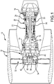
- FIG. 1 is a schematic cross-sectional view of an exemplary gas turbine engine 10 in which a system according to various embodiments may be used.
- Gas turbine engine 10 may include a low pressure unit 12 (that includes low pressure compressor 14 and low pressure turbine 16 connected by low pressure shaft 18, high pressure unit 20 (that includes high pressure compressor 22 and high pressure turbine 24 connected by high pressure shaft 26), combustor 28, nacelle 30, fan 32, fan shaft 34, and epicyclic gear system 36.
- the epicyclic gear system may be a fan drive gear system (FDGS).
- a fan drive gear system (FDGS) follows the fan shaft but separates or decouples the fan 32 from the low pressure unit 12.
- the fan 32 rotates at a slower speed and the low pressure unit 12 operates at a higher speed. This allows each of the fan 32 and the low pressure unit 12 to operate with improved efficiency.
- gas turbine engine 10 has been described, it is to be understood that the methods and systems according to various embodiments as herein described may be used in gas turbine engines having other configurations.
- Epicyclic gear system 36 generally includes an epicyclic gear train including a star gear 38, a ring gear 40, and sun gear 42. As hereinafter described, the epicyclic gear train may be configured as a star gear system 37a (e.g., FIG. 4 ) or a planetary gear system 37b (e.g., FIG. 5 ), as hereinafter described in more detail. Epicyclic gear trains reduce or increase the rotational speed between two rotating shafts or rotors. In response to rotation of low pressure unit 12, epicyclic gear system 36 causes the fan shaft 34 to rotate at a slower rotational velocity than that of low pressure unit 12, but in the opposite direction.
- the sun gear 42 is attached to and rotates with low pressure shaft 18.
- Sun gear 42 is rotatably mounted on low pressure shaft 18.
- Ring gear 40 is connected to fan shaft 34 which turns at the same speed as fan 32.
- Star gear 38 is enmeshed between sun gear 42 and ring gear 40 such that star gear 38 rotates in response to rotation of sun gear 42.
- Star gear 38 is rotatably mounted on a stationary gear carrier 48 by a stationary journal pin 120 ( FIGS. 2 , 4 , and 5 ).
- the star gear 38 circumscribes the journal pin 120.
- the journal pin 120 is disposed inside of the at least one rotatable star gear and connected to the gear carrier 48.
- the journal pins 120 inside each of the star gears ( FIGS.
- journal bearing 44 interconnects the journal pins 120 with each other and, by doing so, also interconnects the star gears 38 to each other (see, FIGS. 4 and 5 ).
- the outer radial surface (i.e., interface surface 52) of journal pin 120 interfaces with the inner surface 60 of the star gear 38.
- the interface surface 52 of journal pin 120 and the inner surface 60 of the star gear 38 are interfacing bearing surfaces.
- a thin, replenishable film of lubricant flows from a distribution recess 58 between each star gear 38 and its journal pin 120 to support the star gear. This arrangement is referred to as a journal bearing 44.
- FIG. 2 is a cross-sectional view of the epicyclic gear system 36 taken through only a single star gear 38.
- Epicyclic gear system 36 includes multiple star gears arranged circumferentially around the sun gear 42 as shown in FIGS. 4 and 5 .
- epicyclic gear system 36 includes the journal pin 120, lubricant manifold 46, the gear carrier 48, and end caps 50.
- Gear carrier 48 is stationarily mounted within gas turbine engine 10 ( FIG. 1 ) to the non-rotating engine case walls radially outboard of epicyclic gear system 36.
- Gear carrier 48 has two generally interfacing faces that support the ends of the stationary journal bearing 44.
- the gear carrier 48 is disposed adjacent the rotatable star gear 38 and sun gear 42.
- Journal pin 120 includes axial passage 54 and radial passages 56. Radial passages 56 fluidly connect to the distribution recess 58.
- Lubricant manifold 46 is connected to feed tube 62.
- a lubricant manifold 46 is disposed adjacent to journal bearing 44 and is fluidly connected thereto.
- Axial passage 54 is fluidly connected to lubricant manifold 46.
- Lubricant manifold 46 is fed pressurized liquid lubricant (typically oil) from other components of the gas turbine engine via feed tube 62. The liquid lubricant from lubricant manifold 46 is supplied through axial passage 54 to radial passages 56.
- the lubricant flows through radial passages 56 into the distribution recess 58 between the journal pin 120 and the star gear 38.
- the distribution recess 58 may extend along the outer radial surface (i.e., interface surface 52) of journal pin 120.
- the liquid lubricant forms a film of lubrication (a "lubrication film") on the journal pin in the distribution recess 58. From distribution recess 58, the lubricant film spreads circumferentially and axially due to viscous forces between star gear 38 and journal pin 120.
- the lubricant film helps to support star gear 38 and reduce friction between inner surface 60 of star gear 38 and interface surface 52 of the journal pin as the star gear 38 rotates.
- End caps 50 are welded or otherwise affixed to journal bearing 44 and press fit into gear carrier 48. End caps 50 and gear carrier 48 provide support for journal bearing 44. Fasteners extend through end caps 50 and connect to gear carrier 48 to act as an anti-rotation feature to keep journal pin 120 and journal bearing 44 stationary (i.e., static).
- the lubricant film thickness between the interface surface 52 of the journal pin 120 and the inner surface 60 of the star gear 38 may be monitored according to systems and methods according to various embodiments as described herein. It is desirable to monitor the lubricant film thickness in real time to substantially ensure that the lubricant thickness is not zero or some value very near zero and preferably, that the lubricant thickness is at least the predetermined minimum lubrication film thickness (e.g., predetermined required lubrication film thickness) and that there is no touchdown between interface surface 52 and inner surface 60 (the "interfacing bearing surfaces") 52 of star gear.
- predetermined minimum lubrication film thickness e.g., predetermined required lubrication film thickness
- the interface surface 52 of journal pin 120 may be provided with a minimum lubricant film thickness of between about 0.00254 mm (100 micro inches) and 0.0508 mm (2000 micro inches). Of course, the minimum lubricant film thickness may be set at any level.
- journal bearing 44 extends radially outward from an axis of symmetry that generally aligns with axial passage 54 to outermost interface surface 52.
- the star gear 38 has the inner surface 60 that extends parallel to interface surface 52 of journal bearing 44. More particularly, inner surface 60 runs against interface surface 52 as star gear 38 rotates.
- the lubricant film spreads circumferentially and axially in a boundary regime between interface surface 52 and inner surface 60 from distribution recess 58 due to viscous forces between star gear 38 and the journal pin. After forming the lubricant film between the journal pin and star gear 38, lubricant is discharged from the axial extremities of the bearing interface. Substantially all the discharged lubricant is directed into the sun/star mesh.
- the directed lubricant cools and lubricates the sun and star gear teeth and then is expelled from the sun/star mesh.
- the lubricant is eventually ejected from the star/ring mesh and centrifugally channeled away from epicyclic gear system 36.
- the gear trains suitable for use in the epicyclic gear system of the aircraft gas turbine engine are depicted, according to various embodiments.
- the gear trains each include the sun gear 42 driven by the low pressure shaft 18, the ring gear 40 radially outboard of the sun gear and connected to the fan shaft 34, and the set of star gears 38 radially intermediate and meshing with the sun and ring gears.
- each star gear 38 circumscribes the journal pin 120 and the thin, replenishable film of lubricant occupies the distribution recess 58 ( FIG. 2 ) between each star gear 38 and its journal pin 120 to support the star gear.
- the sun and ring gears are each rotatable about an axis 128.
- the gear carrier 48 is non-rotatable even though the individual star gears 38 are each rotatable about their respective axes 130.
- the input and output shafts counter-rotate. Lubricant flows through the star gear system to support the star gears 38 on the journal pins 120 and to lubricate and cool the gear teeth.
- the gear train of the epicyclic gear system 36 can alternatively be configured in a different manner sometimes called the planetary gear system 37b as noted previously.
- the star or "planet” gear 38 is rotatably mounted on the gear carrier 48 by the journal pin 120.
- Star gears 38 mesh with sun gear 42.
- Mechanically grounded (i.e., non-rotatable), internally toothed ring gear 40 circumscribes and meshes with star gears 38.
- Input and output shafts extend from sun gear 42 and the gear carrier 48 respectively.
- the input shaft rotatably drives sun gear 42, rotating star gear 38 about its own star gear axis 130, and because ring gear 40 is mechanically grounded, causes star gear 38 to orbit the sun gear 42 in the manner of a planet. Orbital motion of star gear 38 turns the gear carrier 48 and the output shaft in the same direction as the input shaft.
- the gear train of the epicyclic gear system is configured as a star gear system 37a or a planetary gear system 37b, it is desirable to monitor the lubricant film thickness in real time or near real time during gas turbine engine operation.
- a system 100 for monitoring the lubricant film thickness of a journal bearing 44 in the epicyclic gear system is depicted.
- the system 100 comprises one or more conductive elements in electrical communication with a signal processor 110 to detect the lubricant film thickness.
- the system 100 comprises a first electrical lead (solid line 102) having a first end 104 in communication with a first conductive element (e.g., journal pin 120 in FIGS. 3 through 5 ) on a static side of the journal bearing 44 and a second end 108 connected to a signal processor 110 as hereinafter described.
- a first electrical lead solid line 102 having a first end 104 in communication with a first conductive element (e.g., journal pin 120 in FIGS. 3 through 5 ) on a static side of the journal bearing 44 and a second end 108 connected to a signal processor 110 as hereinafter described.
- a second electrical lead (dotted lines 112a, 112b, 112c, 112d, and 112e) representing alternative connection paths for the second electrical lead as hereinafter described) has a first lead end 114 connected to a second conductive element as hereinafter described on a rotating side of the journal bearing 44 and a second lead end 118 of the second electrical lead 112a, 112b, 112c, 112d, or 112e is connected to the signal processor 110 to complete the electrical circuit. More specifically, in the epicyclic gear system configured as a star gear system 37a (e.g., FIG. 4 ), the first conductive element on the static side of the journal bearing 44 may be the journal pin 120 as noted previously.
- the second conductive element on the rotating side of the journal bearing 44 may comprise, for example, a star gear 38, the ring gear 40, the sun gear 42, the input coupling, or the fan shaft 34. Therefore, the second lead end 118 of second electrical lead (dotted line 112a) is depicted as connected to fan shaft 34.
- the second lead end of second electrical lead (dotted line 112b) is depicted as connected to sun gear, dotted line 112c is connected to star gear, dotted line 112d is connected to ring gear, and dotted line 112e is connected to input coupling.
- the first end 104 of the first electrical lead (solid line A) is connected to the first conductive element (e.g., the journal pin 120) on a static side of the journal bearing and the second end is connected to the signal processor 110 as noted previously.
- the first lead end 114 of the second electrical lead may be connected to the second conductive element on the rotating side of the journal bearing 44 and the second lead end 118 of the second electrical lead is connected to the signal processor 110 as noted previously, in order to complete the electrical circuit.
- the first lead end 114 of the second electrical lead in the planetary gear system may be connected to a star gear 38 or the ring gear 40 as depicted in FIG. 5 .
- the signal processor may be used for measuring electrical properties across the lubricant film (from the static side of the journal bearing 44 to the rotating side of the journal bearing 44), between the first electrical lead 102 and the second electrical lead 112.
- an electrical measuring device may be separate from the signal processor 110.
- the measured electrical properties include bearing resistance, bearing capacitance, capacitive reactance, impedance, and combinations thereof.
- the signal processor is electrically connected with the first electrical lead 102 and the second electrical lead 112.
- the electrical property (e.g., bearing resistance and/or bearing capacitance) across the lubricant film is measured to obtain an electrical property measurement using the signal processor 110.
- the signal processor 110 may be in electrical communication with a Wheatstone bridge or other circuitry in order to detect the electrical property measurement.
- the signal processor 110 is configured to generate a lubricant film thickness from the electrical property measurement. More specifically, the signal processor 110 is configured to compare the electrical property measurement with a reference measurement for the electrical property.
- the signal processor 110 is configured to detect contact of the bearing surfaces if the electrical property measurement comprising a bearing resistance is about zero ohms.
- the signal processor is further configured to convert the electrical property measurement into a lubricant film thickness measurement.
- the signal processor 110 converts the electrical property measurement into the lubricant film thickness measurement.
- the lubricant film thickness may be calculated from, for example, bearing capacitance or bearing resistance and other enumerated values such as, for example, shaft diameter, the shaft length to diameter ratio, the shaft eccentricity ratio, and the permittivity/dielectric constant of the lubricant.
- a calculated lubricant film thickness corresponding to the real-time lubricant film thickness may be determined.
- the real-time lubricant film thickness may similarly be determined with a bearing resistance measurement and other enumerated values such as shaft diameter, length to diameter ratio, eccentricity ratio, resistivity of the lubricant, etc. as known in the art.
- the signal processor 110 is further configured to compare the calculated lubricant film thickness measurement with a predetermined minimum lubricant film thickness value. If the calculated lubricant film thickness is less than the predetermined minimum lubricant film thickness, a touchdown of the bearing surfaces may be occurring, necessitating journal bearing maintenance. In response to receiving a signal that the calculated lubricant film thickness is less than the predetermined minimum lubricant film thickness, the signal processor 110 is further configured to generate a signal to an engine control unit 116 such as a full authority digital engine control (FADEC) or an Electronic Centralized Aircraft Monitor (ECAM), according to various embodiments. The signal processor may be in communication with the FADEC or ECAM of the aircraft.
- FADEC full authority digital engine control
- ECAM Electronic Centralized Aircraft Monitor
- signal processor may refer to a portion or module of an engine control unit (e.g., FADEC, ECAM) or to a standalone controller in communication with an engine control unit (e.g., FADEC, ECAM).
- the output signal from the signal processor 110 to the engine control unit 116 may represent an alert.
- the output signal representing the alert/inadequate lubricant film thickness may then be relayed to, for example, ground maintenance crews for investigation into the loss of lubricant film thickness.
- the engine control module may trigger an alert such as a cockpit light, permitting safe shutdown of the gas turbine engine.
- an alert such as a cockpit light
- the signal processor 110 and/or the engine control unit 116 may restrict a subsequent restart of the gas turbine engine.
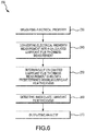
- a method 200 for monitoring lubricant film thickness between bearing surfaces of a journal bearing in an epicyclic gear system of a gas turbine engine begins by measuring the electrical property across the lubricant film (step 230).
- the lubricant film thickness may be determined through use of the signal processor comprising a Wheatstone bridge or other circuitry that measures electrical properties such as bearing resistance, bearing capacitance, capacitive resistance, impedance, and combinations thereof across the film thickness, as hereinafter described.
- the method 200 for monitoring the lubricant film thickness of the journal bearing continues by converting the electrical property measurement into a calculated lubricant film thickness (step 240).
- the calculated lubricant film thickness may be calculated by a mathematical equation that relates the electrical property measurement to the real-time minimum lubricant film thickness.
- the method 200 for monitoring the lubricant film thickness of the journal bearing continues by determining whether the calculated lubricant film thickness is below the predetermined minimum lubricant film thickness threshold (step 250). Determining whether the calculated lubricant film thickness is below the predetermined minimum lubricant film thickness threshold comprises comparing the calculated minimum lubricant film thickness with the predetermined minimum thickness threshold.
- the method 200 for monitoring the lubricant film thickness of the journal bearing continues by detecting an inadequate lubricant film thickness if the calculated lubricant film thickness is below the predetermined minimum thickness (step 260).
- the method for monitoring the lubricant film thickness of the journal bearing continues by sending an output signal representing an alert from the signal processor to the engine control module such as the FADEC or the ECAM of the gas turbine engine (step 270) if the calculated lubricant film thickness is below the predetermined minimum thickness.
- the engine control module such as the FADEC or the ECAM of the gas turbine engine
- a method 300 for controlling the gas turbine engine in response to a thickness of a lubricant film in a journal bearing of an epicyclic gear system of the gas turbine engine is provided.
- the method 300 may include, similar to method 200 and as described extensively above, receiving an electrical property measurement across a lubricant film at step 330 and converting the electrical property measurement into a calculated lubricant film thickness measurement at step 340.
- the method 300 may further include the signal processor and/or engine control unit, in response to determining the calculated lubricant film thickness measurement is below the predetermined minimum lubricant film thickness at step 350, restricting a subsequent restart of the gas turbine engine at step 380.
- the signal processor and/or the engine control unit may, instead of or in addition to indicating an alert, restrict, limit, prevent, or otherwise affect the next restart of the gas turbine engine.
- instructions may be stored on a memory of the signal processor and/or the engine control unit that affect the next restart of the gas turbine engine.
- the aircraft may safely complete the flight during which the inadequate lubricant film thickness is detected, but subsequent flights may be restricted or may be otherwise limited until the lubricant film thickness issue has been resolved or at least addressed (e.g., until a maintenance action is performed).
- the step of restricting the subsequent engine restart of the gas turbine engine comprises preventing subsequent restart. That is, the engine may be prevented from being restarted until the inadequate lubricant film thickness issue has been resolved or at least addressed.
- step 380 includes limiting a subsequent operating state of the gas turbine engine. That is, step 380 may include preventing the gas turbine engine from operating at elevated speeds. For example, the aircraft may be prevented from operating above idle after the subsequent restart until the lubricant film thickness issue has been resolved.
- journal bearings While monitoring the lubricant film thickness of journal bearings has been described, it is to be understood that the lubricant film thickness of rolling element bearings, gear boxes, and gear meshes that rely on maintaining a minimum lubricant film thickness between bearing surfaces may benefit from various embodiments as described herein. It is to be appreciated that the systems and methods for monitoring lubricant film thickness according to various embodiments of the present disclosure minimize gear system and engine failure, thereby resulting in improved performance and operability.
- a method 400 for controlling the gas turbine engine may include receiving, via signal processor from a sensor, an operating condition of the gas turbine engine at step 430.
- the operating condition 430 may include a parameter detected from a sensor.
- the method 400 may further include determining whether the operating condition is within an acceptable threshold at step 450. In response to the operating condition being outside the acceptable threshold, the signal processor and/or the engine control until may restrict a subsequent restart of the gas turbine engine at step 480.
- the signal processor and/or the engine control unit instead of or in addition to only indicating an alert pertaining to the detected operating condition, may restrict, limit, prevent, or otherwise affect the next restart of the gas turbine engine.
- instructions may be stored on a memory of the signal processor and/or the engine control unit that affect the next restart of the gas turbine engine.
- the aircraft may safely complete the flight during which the inadequate lubricant film thickness is detected, but subsequent flights may be restricted or may be otherwise limited until the lubricant film thickness issue has been resolved or at least addressed (e.g., until a maintenance action is performed).
- the step of restricting the subsequent engine restart of the gas turbine engine comprises preventing subsequent restart. That is, the engine may be prevented from being restarted until the inadequate lubricant film thickness issue has been resolved or at least addressed.
- step 480 includes limiting a subsequent operating state of the gas turbine engine. That is, step 480 may include preventing the gas turbine engine from operating at elevated speeds. For example, the aircraft may be prevented from operating above idle after the subsequent restart until the lubricant film thickness issue has been resolved.
- the operating condition received/detected at step 430 of the method 400 may be a temperature from a temperature sensor, a pressure from a pressure sensor, a position from a position sensor, a vibratory response from a vibration sensor, a rotating speed from a speed sensor, a lubricant thickness from a lubricant film thickness sensor, and/or a sensor status (e.g., a status indicating a failed sensor).
- the operating condition may be an exhaust gas temperature, a compressor exit temperature, a main lubricant temperature, a total temperature at the turbine exit, and/or a fan turbine inlet temperature.
- the operating condition may be a main oil pressure, a fuel pressure, an oil filter pressure differential, a fuel filter pressure differential, an accessory oil pressure, and/or an engine pressure ratio.
- the operating condition may be a thrust reverser door position, a fuel metering valve position, an exhaust nozzle position, a compressor variable vane position, and/or an oil tank level.
- the operating condition may be a fan shaft overspeed, a high rotor overspeed, and/or a low rotor overspeed.
- any reference to attached, fixed, connected, coupled or the like may include permanent (e.g., integral), removable, temporary, partial, full, and/or any other possible attachment option.
- permanent e.g., integral
- removable temporary, partial, full
- any other possible attachment option e.g., permanent, temporary, partial, full, and/or any other possible attachment option.
- Different cross-hatching is used throughout the figures to denote different parts but not necessarily to denote the same or different materials.
- any of the method or process descriptions may be executed in any order and are not necessarily limited to the order presented.
- any reference to singular includes plural embodiments, and any reference to more than one component or step may include a singular embodiment or step.
- Elements and steps in the figures are illustrated for simplicity and clarity and have not necessarily been rendered according to any particular sequence. For example, steps that may be performed concurrently or in different order are illustrated in the figures to help to improve understanding of embodiments of the present disclosure.
- Any reference to attached, fixed, connected or the like may include permanent, removable, temporary, partial, full and/or any other possible attachment option. Additionally, any reference to without contact (or similar phrases) may also include reduced contact or minimal contact. Surface shading lines may be used throughout the figures to denote different parts or areas but not necessarily to denote the same or different materials. In some cases, reference coordinates may be specific to each figure.
- references to "one embodiment”, “an embodiment”, “various embodiments”, etc. indicate that the embodiment described may include a particular feature, structure, or characteristic, but every embodiment may not necessarily include the particular feature, structure, or characteristic. Moreover, such phrases are not necessarily referring to the same embodiment. Further, when a particular feature, structure, or characteristic is described in connection with an embodiment, it is submitted that it is within the knowledge of one skilled in the art to affect such feature, structure, or characteristic in connection with other embodiments whether or not explicitly described. After reading the description, it will be apparent to one skilled in the relevant art(s) how to implement the disclosure in alternative embodiments.
Landscapes
- Engineering & Computer Science (AREA)
- General Engineering & Computer Science (AREA)
- Mechanical Engineering (AREA)
- Physics & Mathematics (AREA)
- General Physics & Mathematics (AREA)
Abstract
Description
- The present disclosure relates to gas turbine engines, and more specifically, to systems and methods for monitoring and controlling the operation of gas turbine engines.
- Aircraft gas turbine engines may utilize an oil-lubricated journal bearing within an epicyclic star gear or planetary gear system in either a turbofan or turboprop configuration. For the reliable performance of the oil-lubricated journal bearing, an adequate amount of oil (i.e., a minimum lubricant film thickness) is used to separate the two bearing surfaces of the journal bearing under relative motion. Conventional methods for monitoring lubrication film thickness are indirect methods, such as particle detection or measurements of thermal output. These conventional methods do not permit direct measurement of the lubrication film thickness of a journal bearing in an epicyclic gear system of an operating gas turbine engine in real time. Further, conventional methods and systems for monitoring and controlling gas turbine engines often trigger an alert or other notification, which can be ignored or dismissed without resolving or at least addressing the underlying issue.
- Disclosed herein, according to various embodiments, is a method for controlling a gas turbine engine in response to a thickness of a lubricant film in a journal bearing of an epicyclic gear system of the gas turbine engine. The method may include receiving, by a signal processor from a sensor, an electrical property measurement across the lubricant film. The method may also include converting, by the signal processor, the electrical property measurement into a calculated lubricant film thickness measurement and determining, by the signal processor, whether the calculated lubricant film thickness measurement is below a predetermined minimum lubricant film thickness. Still further, the method includes, in response to the calculated lubricant film thickness measurement being below the predetermined minimum lubricant film thickness, restricting, by the signal processor, a subsequent engine restart of the gas turbine engine.
- In various embodiments, restricting the subsequent engine restart of the gas turbine engine comprises preventing the subsequent restart. In various embodiments, restricting the subsequent engine restart of the gas turbine engine comprises limiting a subsequent operating state of the gas turbine engine after the subsequent restart. For example, the subsequent operating state may be an operating speed of the gas turbine engine. In various embodiments, limiting the subsequent operating state of the gas turbine engine comprises preventing the gas turbine engine from operating above idle after the subsequent restart.
- In various embodiments, the method further comprises measuring, by an electrical circuit, an electrical property across the lubricant film to obtain the electrical property measurement. Measuring the electrical property may include measuring at least one of bearing resistance, bearing capacitance, impedance, or capacitive reactance. The method may include comprising comparing the electrical property measurement with a reference measurement for the electrical property and detecting contact of the bearing surfaces if the electrical property measurement comprising a bearing resistance is about zero. In various embodiments, converting the electrical property measurement into the calculated lubricant film thickness measurement comprises calculating a lubricant film thickness from the electrical property measurement.
- Also disclosed herein, according to various embodiments, is a system for controlling a gas turbine engine in response to a thickness of a lubricant film in a journal bearing of an epicyclic gear system of the gas turbine engine. The system may include a first electrical lead having a first end in communication with a first conductive element on a static side of the journal bearing and a second end connected to a signal processor. The system may also include a second electrical lead having a first lead end connected to a second conductive element on a rotating side of the journal bearing and a second lead end connected to the signal processor to complete an electrical circuit, the signal processor electrically connected to the first electrical lead and the second electrical lead. The signal processor is configured to, according to various embodiments, measure an electrical property of the electrical circuit to obtain an electrical property measurement and compare the electrical property measurement with a reference measurement for the electrical property and detect contact of the bearing surfaces if the electrical property measurement comprising a bearing resistance is about zero. The signal processor may further be configured to convert the electrical property measurement into a calculated lubricant film thickness measurement and compare the calculated lubricant film thickness measurement with a predetermined minimum lubricant film thickness. Still further, the signal processor may restrict a subsequent engine restart of the gas turbine engine if the calculated lubricant film thickness measurement is less than the predetermined minimum lubricant film thickness.
- In various embodiments, the epicyclic gear system comprises a star gear system or a planetary gear system. The first conductive element on the static side of the journal bearing may be a journal pin. The second conductive element on the rotating side of the journal bearing may comprise a star gear, a ring gear, a sun gear, an input coupling, or a fan shaft. The electric property measurement comprises at least one of bearing resistance, bearing capacitance, capacitive reactance, or impedance, according to various embodiments.
- Also disclosed herein, according to various embodiments, is a method for controlling a gas turbine engine. The method may include receiving, by a signal processor from a sensor, an operating condition of the gas turbine engine and determining, by the signal processor, whether the operating condition is within an acceptable threshold. In response to the operating condition being outside the acceptable threshold, the method may include restricting, by the signal processor, a subsequent engine restart of the gas turbine engine.
- Restricting the subsequent engine restart of the gas turbine engine may comprise preventing the subsequent restart. In various embodiments, restricting the subsequent engine restart of the gas turbine engine comprises limiting a subsequent operating state of the gas turbine engine after the subsequent restart. The subsequent operating state may be an operating speed of the gas turbine engine. In various embodiments, limiting the subsequent operating state of the gas turbine engine comprises preventing the gas turbine engine from operating above idle after the subsequent restart. In various embodiments, the operating condition of the gas turbine engine comprises at least one of: a temperature from a temperature sensor, a pressure from a pressure sensor, a position from a position sensor, a vibratory response from a vibration sensor, a rotating speed from a speed sensor, a lubricant thickness from a lubricant film thickness sensor, and a sensor status.
- The subject matter of the present disclosure is particularly pointed out and distinctly claimed in the concluding portion of the specification. A more complete understanding of the present disclosure, however, may best be obtained by referring to the detailed description and claims when considered in connection with the drawing figures, wherein like numerals denote like elements.
-
FIG. 1 is a schematic cross sectional view of an aircraft gas turbine engine with an epicyclic gear system comprising a gear train, according to various embodiments; -
FIG. 2 is a schematic cross sectional view of the epicyclic gear system ofFIG. 1 , according to various embodiments; -
FIG. 3 is another schematic cross sectional side view of a portion of the aircraft gas turbine engine ofFIG. 1 , illustrating a system for monitoring the lubricant film thickness of a journal bearing in the epicyclic gear system thereof, according to various embodiments; -
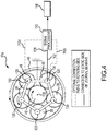
FIG. 4 is a diagrammatic view of the gear train ofFIG. 1 configured as a star gear system taken along section 4-4 ofFIG. 2 , illustrating by a solid line location where a first electrical circuit lead may be connected to a static side of the journal bearing and by dotted lines where a second electrical circuit lead may be connected to a rotating side of the journal bearing for monitoring the lubricant film thickness of the journal bearing, according to various embodiments; -
FIG. 5 is a diagrammatic view similar toFIG. 4 illustrating a gear train configured as a planetary gear system, illustrating by dotted line locations where the first electrical circuit lead may be connected to the rotating side of the journal bearing and a solid line where a second electrical circuit lead may be connected to the static side of the journal bearing for monitoring the lubricant film thickness of the journal bearing, according to various embodiments; -
FIG. 6 is a schematic flow chart diagram of a method for monitoring the lubricant film thickness of a journal bearing in an epicyclic gear system of a gas turbine engine, according to various embodiments; -
FIG. 7 is a schematic flow chart diagram of a method for controlling a gas turbine engine in response to a thickness of a lubricant film in a journal bearing of an epicyclic gear system of the gas turbine engine, according to various embodiments; and -
FIG. 8 is a schematic flow chart diagram of a method for controlling a gas turbine, according to various embodiments. - The detailed description of exemplary embodiments herein makes reference to the accompanying drawings, which show exemplary embodiments by way of illustration. While these exemplary embodiments are described in sufficient detail to enable those skilled in the art to practice the inventions, it should be understood that other embodiments may be realized and that logical changes and adaptations in design and construction may be made in accordance with the present inventions and the teachings herein. Thus, the detailed description herein is presented for purposes of illustration only and not of limitation. The scope of the present inventions is defined by the appended claims.
- Various embodiments are directed to systems and methods for monitoring the lubricant film thickness of a journal bearing in an epicyclic gear system of a gas turbine engine. More particularly, the systems and methods according to various embodiments permit real-time measurement of the lubricant film thickness between the interfacing bearing surfaces of the journal bearing in the epicyclic gear system, thereby maintaining performance and operability of the epicyclic gear system and gas turbine engine. Monitoring also helps ensure that engine safety is maintained.
-
FIG. 1 is a schematic cross-sectional view of an exemplarygas turbine engine 10 in which a system according to various embodiments may be used.Gas turbine engine 10 may include a low pressure unit 12 (that includeslow pressure compressor 14 andlow pressure turbine 16 connected bylow pressure shaft 18, high pressure unit 20 (that includes high pressure compressor 22 andhigh pressure turbine 24 connected by high pressure shaft 26),combustor 28,nacelle 30,fan 32,fan shaft 34, andepicyclic gear system 36. The epicyclic gear system may be a fan drive gear system (FDGS). A fan drive gear system (FDGS) follows the fan shaft but separates or decouples thefan 32 from thelow pressure unit 12. Thefan 32 rotates at a slower speed and thelow pressure unit 12 operates at a higher speed. This allows each of thefan 32 and thelow pressure unit 12 to operate with improved efficiency. Whilegas turbine engine 10 has been described, it is to be understood that the methods and systems according to various embodiments as herein described may be used in gas turbine engines having other configurations. - As shown in the exemplary gas turbine engine of
FIG. 1 ,low pressure unit 12 is coupled tofan shaft 34 via theepicyclic gear system 36.Epicyclic gear system 36 generally includes an epicyclic gear train including astar gear 38, aring gear 40, andsun gear 42. As hereinafter described, the epicyclic gear train may be configured as astar gear system 37a (e.g.,FIG. 4 ) or aplanetary gear system 37b (e.g.,FIG. 5 ), as hereinafter described in more detail. Epicyclic gear trains reduce or increase the rotational speed between two rotating shafts or rotors. In response to rotation oflow pressure unit 12,epicyclic gear system 36 causes thefan shaft 34 to rotate at a slower rotational velocity than that oflow pressure unit 12, but in the opposite direction. - Still referring to
FIG. 1 , thesun gear 42 is attached to and rotates withlow pressure shaft 18.Sun gear 42 is rotatably mounted onlow pressure shaft 18.Ring gear 40 is connected tofan shaft 34 which turns at the same speed asfan 32.Star gear 38 is enmeshed betweensun gear 42 andring gear 40 such thatstar gear 38 rotates in response to rotation ofsun gear 42.Star gear 38 is rotatably mounted on astationary gear carrier 48 by a stationary journal pin 120 (FIGS. 2 ,4 , and5 ). Thestar gear 38 circumscribes thejournal pin 120. Thejournal pin 120 is disposed inside of the at least one rotatable star gear and connected to thegear carrier 48. The journal pins 120 inside each of the star gears (FIGS. 4 and5 ) are all supported by thegear carrier 48. Thegear carrier 48 interconnects the journal pins 120 with each other and, by doing so, also interconnects the star gears 38 to each other (see,FIGS. 4 and5 ). The outer radial surface (i.e., interface surface 52) ofjournal pin 120 interfaces with theinner surface 60 of thestar gear 38. Thus, theinterface surface 52 ofjournal pin 120 and theinner surface 60 of thestar gear 38 are interfacing bearing surfaces. A thin, replenishable film of lubricant flows from adistribution recess 58 between eachstar gear 38 and itsjournal pin 120 to support the star gear. This arrangement is referred to as ajournal bearing 44. -
FIG. 2 is a cross-sectional view of theepicyclic gear system 36 taken through only asingle star gear 38.Epicyclic gear system 36, however, includes multiple star gears arranged circumferentially around thesun gear 42 as shown inFIGS. 4 and5 . In addition tostar gear 38,ring gear 40, andsun gear 42,epicyclic gear system 36 includes thejournal pin 120,lubricant manifold 46, thegear carrier 48, andend caps 50.Gear carrier 48 is stationarily mounted within gas turbine engine 10 (FIG. 1 ) to the non-rotating engine case walls radially outboard ofepicyclic gear system 36.Gear carrier 48 has two generally interfacing faces that support the ends of the stationary journal bearing 44. Thegear carrier 48 is disposed adjacent therotatable star gear 38 andsun gear 42.Journal pin 120 includesaxial passage 54 andradial passages 56.Radial passages 56 fluidly connect to thedistribution recess 58.Lubricant manifold 46 is connected to feedtube 62. Alubricant manifold 46 is disposed adjacent to journal bearing 44 and is fluidly connected thereto.Axial passage 54 is fluidly connected tolubricant manifold 46.Lubricant manifold 46 is fed pressurized liquid lubricant (typically oil) from other components of the gas turbine engine viafeed tube 62. The liquid lubricant fromlubricant manifold 46 is supplied throughaxial passage 54 toradial passages 56. The lubricant flows throughradial passages 56 into thedistribution recess 58 between thejournal pin 120 and thestar gear 38. Thedistribution recess 58 may extend along the outer radial surface (i.e., interface surface 52) ofjournal pin 120. The liquid lubricant forms a film of lubrication (a "lubrication film") on the journal pin in thedistribution recess 58. Fromdistribution recess 58, the lubricant film spreads circumferentially and axially due to viscous forces betweenstar gear 38 andjournal pin 120. The lubricant film helps to supportstar gear 38 and reduce friction betweeninner surface 60 ofstar gear 38 andinterface surface 52 of the journal pin as thestar gear 38 rotates. - End caps 50 are welded or otherwise affixed to journal bearing 44 and press fit into
gear carrier 48. End caps 50 andgear carrier 48 provide support forjournal bearing 44. Fasteners extend throughend caps 50 and connect to gearcarrier 48 to act as an anti-rotation feature to keepjournal pin 120 and journal bearing 44 stationary (i.e., static). - To substantially ensure that a minimum lubricant film thickness is maintained during gas turbine engine operation, the lubricant film thickness between the
interface surface 52 of thejournal pin 120 and theinner surface 60 of thestar gear 38 may be monitored according to systems and methods according to various embodiments as described herein. It is desirable to monitor the lubricant film thickness in real time to substantially ensure that the lubricant thickness is not zero or some value very near zero and preferably, that the lubricant thickness is at least the predetermined minimum lubrication film thickness (e.g., predetermined required lubrication film thickness) and that there is no touchdown betweeninterface surface 52 and inner surface 60 (the "interfacing bearing surfaces") 52 of star gear. Theinterface surface 52 ofjournal pin 120 may be provided with a minimum lubricant film thickness of between about 0.00254 mm (100 micro inches) and 0.0508 mm (2000 micro inches). Of course, the minimum lubricant film thickness may be set at any level. - As further shown in
FIG. 2 , journal bearing 44 extends radially outward from an axis of symmetry that generally aligns withaxial passage 54 tooutermost interface surface 52. Thestar gear 38 has theinner surface 60 that extends parallel to interfacesurface 52 of journal bearing 44. More particularly,inner surface 60 runs againstinterface surface 52 asstar gear 38 rotates. The lubricant film spreads circumferentially and axially in a boundary regime betweeninterface surface 52 andinner surface 60 fromdistribution recess 58 due to viscous forces betweenstar gear 38 and the journal pin. After forming the lubricant film between the journal pin andstar gear 38, lubricant is discharged from the axial extremities of the bearing interface. Substantially all the discharged lubricant is directed into the sun/star mesh. The directed lubricant cools and lubricates the sun and star gear teeth and then is expelled from the sun/star mesh. The lubricant is eventually ejected from the star/ring mesh and centrifugally channeled away fromepicyclic gear system 36. - Referring again to
FIGS. 4 and5 , the gear trains suitable for use in the epicyclic gear system of the aircraft gas turbine engine are depicted, according to various embodiments. As noted previously, the gear trains each include thesun gear 42 driven by thelow pressure shaft 18, thering gear 40 radially outboard of the sun gear and connected to thefan shaft 34, and the set of star gears 38 radially intermediate and meshing with the sun and ring gears. As noted previously, eachstar gear 38 circumscribes thejournal pin 120 and the thin, replenishable film of lubricant occupies the distribution recess 58 (FIG. 2 ) between eachstar gear 38 and itsjournal pin 120 to support the star gear. - Referring now specifically to
FIG. 4 in which the epicyclic gear train is configured as thestar gear system 37a, the sun and ring gears are each rotatable about anaxis 128. Thegear carrier 48 is non-rotatable even though the individual star gears 38 are each rotatable about theirrespective axes 130. As seen best inFIG. 4 , the input and output shafts counter-rotate. Lubricant flows through the star gear system to support the star gears 38 on the journal pins 120 and to lubricate and cool the gear teeth. - Referring now to
FIG. 5 , the gear train of theepicyclic gear system 36 can alternatively be configured in a different manner sometimes called theplanetary gear system 37b as noted previously. In this configuration, the star or "planet"gear 38 is rotatably mounted on thegear carrier 48 by thejournal pin 120. Star gears 38 mesh withsun gear 42. Mechanically grounded (i.e., non-rotatable), internallytoothed ring gear 40 circumscribes and meshes with star gears 38. Input and output shafts extend fromsun gear 42 and thegear carrier 48 respectively. During operation, the input shaft rotatably drivessun gear 42, rotatingstar gear 38 about its ownstar gear axis 130, and becausering gear 40 is mechanically grounded, causesstar gear 38 to orbit thesun gear 42 in the manner of a planet. Orbital motion ofstar gear 38 turns thegear carrier 48 and the output shaft in the same direction as the input shaft. Whether the gear train of the epicyclic gear system is configured as astar gear system 37a or aplanetary gear system 37b, it is desirable to monitor the lubricant film thickness in real time or near real time during gas turbine engine operation. - Still referring to
FIGS. 4 and5 and now toFIG. 3 , according to various embodiments, asystem 100 for monitoring the lubricant film thickness of a journal bearing 44 in the epicyclic gear system is depicted. Thesystem 100 comprises one or more conductive elements in electrical communication with asignal processor 110 to detect the lubricant film thickness. - According to various embodiments, the
system 100 comprises a first electrical lead (solid line 102) having afirst end 104 in communication with a first conductive element (e.g.,journal pin 120 inFIGS. 3 through 5 ) on a static side of the journal bearing 44 and asecond end 108 connected to asignal processor 110 as hereinafter described. A second electrical lead (dottedlines lead end 114 connected to a second conductive element as hereinafter described on a rotating side of the journal bearing 44 and a secondlead end 118 of the secondelectrical lead signal processor 110 to complete the electrical circuit. More specifically, in the epicyclic gear system configured as astar gear system 37a (e.g.,FIG. 4 ), the first conductive element on the static side of the journal bearing 44 may be thejournal pin 120 as noted previously. The second conductive element on the rotating side of the journal bearing 44 may comprise, for example, astar gear 38, thering gear 40, thesun gear 42, the input coupling, or thefan shaft 34. Therefore, the secondlead end 118 of second electrical lead (dottedline 112a) is depicted as connected tofan shaft 34. The second lead end of second electrical lead (dottedline 112b) is depicted as connected to sun gear, dottedline 112c is connected to star gear, dottedline 112d is connected to ring gear, and dottedline 112e is connected to input coupling. - Still referring to
FIG. 3 and now toFIG. 5 depicting the epicyclic gear train configured as a planetary gear system, according to various embodiments, thefirst end 104 of the first electrical lead (solid line A) is connected to the first conductive element (e.g., the journal pin 120) on a static side of the journal bearing and the second end is connected to thesignal processor 110 as noted previously. The firstlead end 114 of the second electrical lead may be connected to the second conductive element on the rotating side of the journal bearing 44 and the secondlead end 118 of the second electrical lead is connected to thesignal processor 110 as noted previously, in order to complete the electrical circuit. Thus, the firstlead end 114 of the second electrical lead in the planetary gear system may be connected to astar gear 38 or thering gear 40 as depicted inFIG. 5 . - The signal processor may be used for measuring electrical properties across the lubricant film (from the static side of the journal bearing 44 to the rotating side of the journal bearing 44), between the first
electrical lead 102 and the second electrical lead 112. In various embodiments, an electrical measuring device may be separate from thesignal processor 110. The measured electrical properties include bearing resistance, bearing capacitance, capacitive reactance, impedance, and combinations thereof. The signal processor is electrically connected with the firstelectrical lead 102 and the second electrical lead 112. - The electrical property (e.g., bearing resistance and/or bearing capacitance) across the lubricant film is measured to obtain an electrical property measurement using the
signal processor 110. In various embodiments, thesignal processor 110 may be in electrical communication with a Wheatstone bridge or other circuitry in order to detect the electrical property measurement. Thesignal processor 110 is configured to generate a lubricant film thickness from the electrical property measurement. More specifically, thesignal processor 110 is configured to compare the electrical property measurement with a reference measurement for the electrical property. Thesignal processor 110 is configured to detect contact of the bearing surfaces if the electrical property measurement comprising a bearing resistance is about zero ohms. The signal processor is further configured to convert the electrical property measurement into a lubricant film thickness measurement. Using known equations, thesignal processor 110 converts the electrical property measurement into the lubricant film thickness measurement. The lubricant film thickness may be calculated from, for example, bearing capacitance or bearing resistance and other enumerated values such as, for example, shaft diameter, the shaft length to diameter ratio, the shaft eccentricity ratio, and the permittivity/dielectric constant of the lubricant. A calculated lubricant film thickness corresponding to the real-time lubricant film thickness may be determined. The real-time lubricant film thickness may similarly be determined with a bearing resistance measurement and other enumerated values such as shaft diameter, length to diameter ratio, eccentricity ratio, resistivity of the lubricant, etc. as known in the art. - The
signal processor 110 is further configured to compare the calculated lubricant film thickness measurement with a predetermined minimum lubricant film thickness value. If the calculated lubricant film thickness is less than the predetermined minimum lubricant film thickness, a touchdown of the bearing surfaces may be occurring, necessitating journal bearing maintenance. In response to receiving a signal that the calculated lubricant film thickness is less than the predetermined minimum lubricant film thickness, thesignal processor 110 is further configured to generate a signal to anengine control unit 116 such as a full authority digital engine control (FADEC) or an Electronic Centralized Aircraft Monitor (ECAM), according to various embodiments. The signal processor may be in communication with the FADEC or ECAM of the aircraft. As used herein the term "signal processor" may refer to a portion or module of an engine control unit (e.g., FADEC, ECAM) or to a standalone controller in communication with an engine control unit (e.g., FADEC, ECAM). The output signal from thesignal processor 110 to theengine control unit 116 may represent an alert. The output signal representing the alert/inadequate lubricant film thickness may then be relayed to, for example, ground maintenance crews for investigation into the loss of lubricant film thickness. In various embodiments, and as described in greater detail below with reference toFIG. 6 , if the lubricant film thickness is substantially lost such that substantially no resistance is measured across the lubricant film, the engine control module may trigger an alert such as a cockpit light, permitting safe shutdown of the gas turbine engine. In various embodiments, and as described in greater detail below with reference toFIG. 7 , instead of or in addition to triggering an alert, thesignal processor 110 and/or theengine control unit 116 may restrict a subsequent restart of the gas turbine engine. - Referring now to
FIG. 6 , according to various embodiments, amethod 200 for monitoring lubricant film thickness between bearing surfaces of a journal bearing in an epicyclic gear system of a gas turbine engine begins by measuring the electrical property across the lubricant film (step 230). The lubricant film thickness may be determined through use of the signal processor comprising a Wheatstone bridge or other circuitry that measures electrical properties such as bearing resistance, bearing capacitance, capacitive resistance, impedance, and combinations thereof across the film thickness, as hereinafter described. - The
method 200 for monitoring the lubricant film thickness of the journal bearing continues by converting the electrical property measurement into a calculated lubricant film thickness (step 240). The calculated lubricant film thickness may be calculated by a mathematical equation that relates the electrical property measurement to the real-time minimum lubricant film thickness. - The
method 200 for monitoring the lubricant film thickness of the journal bearing continues by determining whether the calculated lubricant film thickness is below the predetermined minimum lubricant film thickness threshold (step 250). Determining whether the calculated lubricant film thickness is below the predetermined minimum lubricant film thickness threshold comprises comparing the calculated minimum lubricant film thickness with the predetermined minimum thickness threshold. - The
method 200 for monitoring the lubricant film thickness of the journal bearing continues by detecting an inadequate lubricant film thickness if the calculated lubricant film thickness is below the predetermined minimum thickness (step 260). - The method for monitoring the lubricant film thickness of the journal bearing continues by sending an output signal representing an alert from the signal processor to the engine control module such as the FADEC or the ECAM of the gas turbine engine (step 270) if the calculated lubricant film thickness is below the predetermined minimum thickness.
- In various embodiments, and with reference to
FIG. 7 , amethod 300 for controlling the gas turbine engine in response to a thickness of a lubricant film in a journal bearing of an epicyclic gear system of the gas turbine engine is provided. Themethod 300 may include, similar tomethod 200 and as described extensively above, receiving an electrical property measurement across a lubricant film atstep 330 and converting the electrical property measurement into a calculated lubricant film thickness measurement atstep 340. Themethod 300 may further include the signal processor and/or engine control unit, in response to determining the calculated lubricant film thickness measurement is below the predetermined minimum lubricant film thickness atstep 350, restricting a subsequent restart of the gas turbine engine atstep 380. Said differently, the signal processor and/or the engine control unit may, instead of or in addition to indicating an alert, restrict, limit, prevent, or otherwise affect the next restart of the gas turbine engine. For example, instructions may be stored on a memory of the signal processor and/or the engine control unit that affect the next restart of the gas turbine engine. In such embodiments, the aircraft may safely complete the flight during which the inadequate lubricant film thickness is detected, but subsequent flights may be restricted or may be otherwise limited until the lubricant film thickness issue has been resolved or at least addressed (e.g., until a maintenance action is performed). - In various embodiments, the step of restricting the subsequent engine restart of the gas turbine engine (step 380) comprises preventing subsequent restart. That is, the engine may be prevented from being restarted until the inadequate lubricant film thickness issue has been resolved or at least addressed. In various embodiments,
step 380 includes limiting a subsequent operating state of the gas turbine engine. That is,step 380 may include preventing the gas turbine engine from operating at elevated speeds. For example, the aircraft may be prevented from operating above idle after the subsequent restart until the lubricant film thickness issue has been resolved. - While monitoring the lubricant film thickness of journal bearings has been described, it is to be understood that the lubricant film thickness of rolling element bearings, gear boxes, and gear meshes that rely on maintaining a minimum lubricant film thickness between bearing surfaces may benefit from various embodiments as described herein. It is to be appreciated that the systems and methods for monitoring lubricant film thickness according to various embodiments of the present disclosure minimize gear system and engine failure, thereby resulting in improved performance and operability.
- In various embodiments, and with reference to
FIG. 8 , amethod 400 for controlling the gas turbine engine is provided. Themethod 400 may include receiving, via signal processor from a sensor, an operating condition of the gas turbine engine atstep 430. Theoperating condition 430 may include a parameter detected from a sensor. Themethod 400 may further include determining whether the operating condition is within an acceptable threshold atstep 450. In response to the operating condition being outside the acceptable threshold, the signal processor and/or the engine control until may restrict a subsequent restart of the gas turbine engine atstep 480. Said differently, the signal processor and/or the engine control unit, instead of or in addition to only indicating an alert pertaining to the detected operating condition, may restrict, limit, prevent, or otherwise affect the next restart of the gas turbine engine. For example, instructions may be stored on a memory of the signal processor and/or the engine control unit that affect the next restart of the gas turbine engine. In such embodiments, the aircraft may safely complete the flight during which the inadequate lubricant film thickness is detected, but subsequent flights may be restricted or may be otherwise limited until the lubricant film thickness issue has been resolved or at least addressed (e.g., until a maintenance action is performed). - In various embodiments, the step of restricting the subsequent engine restart of the gas turbine engine (step 480) comprises preventing subsequent restart. That is, the engine may be prevented from being restarted until the inadequate lubricant film thickness issue has been resolved or at least addressed. In various embodiments,
step 480 includes limiting a subsequent operating state of the gas turbine engine. That is,step 480 may include preventing the gas turbine engine from operating at elevated speeds. For example, the aircraft may be prevented from operating above idle after the subsequent restart until the lubricant film thickness issue has been resolved. - The operating condition received/detected at
step 430 of themethod 400 may be a temperature from a temperature sensor, a pressure from a pressure sensor, a position from a position sensor, a vibratory response from a vibration sensor, a rotating speed from a speed sensor, a lubricant thickness from a lubricant film thickness sensor, and/or a sensor status (e.g., a status indicating a failed sensor). For example, the operating condition may be an exhaust gas temperature, a compressor exit temperature, a main lubricant temperature, a total temperature at the turbine exit, and/or a fan turbine inlet temperature. In various embodiments, the operating condition may be a main oil pressure, a fuel pressure, an oil filter pressure differential, a fuel filter pressure differential, an accessory oil pressure, and/or an engine pressure ratio. In various embodiments, the operating condition may be a thrust reverser door position, a fuel metering valve position, an exhaust nozzle position, a compressor variable vane position, and/or an oil tank level. In various embodiments, the operating condition may be a fan shaft overspeed, a high rotor overspeed, and/or a low rotor overspeed. - Benefits, other advantages, and solutions to problems have been described herein with regard to specific embodiments. Furthermore, the connecting lines shown in the various figures contained herein are intended to represent exemplary functional relationships and/or physical couplings between the various elements. It should be noted that many alternative or additional functional relationships or physical connections may be present in a practical system. However, the benefits, advantages, solutions to problems, and any elements that may cause any benefit, advantage, or solution to occur or become more pronounced are not to be construed as critical, required, or essential features or elements of the disclosure.
- The scope of the disclosure is accordingly to be limited by nothing other than the appended claims, in which reference to an element in the singular is not intended to mean "one and only one" unless explicitly so stated, but rather "one or more." It is to be understood that unless specifically stated otherwise, references to "a," "an," and/or "the" may include one or more than one and that reference to an item in the singular may also include the item in the plural. All ranges and ratio limits disclosed herein may be combined.
- Moreover, where a phrase similar to "at least one of A, B, and C" is used in the claims, it is intended that the phrase be interpreted to mean that A alone may be present in an embodiment, B alone may be present in an embodiment, C alone may be present in an embodiment, or that any combination of the elements A, B and C may be present in a single embodiment; for example, A and B, A and C, B and C, or A and B and C.
- Also, any reference to attached, fixed, connected, coupled or the like may include permanent (e.g., integral), removable, temporary, partial, full, and/or any other possible attachment option. Different cross-hatching is used throughout the figures to denote different parts but not necessarily to denote the same or different materials.
- The steps recited in any of the method or process descriptions may be executed in any order and are not necessarily limited to the order presented. Furthermore, any reference to singular includes plural embodiments, and any reference to more than one component or step may include a singular embodiment or step. Elements and steps in the figures are illustrated for simplicity and clarity and have not necessarily been rendered according to any particular sequence. For example, steps that may be performed concurrently or in different order are illustrated in the figures to help to improve understanding of embodiments of the present disclosure.
- Any reference to attached, fixed, connected or the like may include permanent, removable, temporary, partial, full and/or any other possible attachment option. Additionally, any reference to without contact (or similar phrases) may also include reduced contact or minimal contact. Surface shading lines may be used throughout the figures to denote different parts or areas but not necessarily to denote the same or different materials. In some cases, reference coordinates may be specific to each figure.
- Systems, methods and apparatus are provided herein. In the detailed description herein, references to "one embodiment", "an embodiment", "various embodiments", etc., indicate that the embodiment described may include a particular feature, structure, or characteristic, but every embodiment may not necessarily include the particular feature, structure, or characteristic. Moreover, such phrases are not necessarily referring to the same embodiment. Further, when a particular feature, structure, or characteristic is described in connection with an embodiment, it is submitted that it is within the knowledge of one skilled in the art to affect such feature, structure, or characteristic in connection with other embodiments whether or not explicitly described. After reading the description, it will be apparent to one skilled in the relevant art(s) how to implement the disclosure in alternative embodiments.
- Furthermore, no element, component, or method step in the present disclosure is intended to be dedicated to the public regardless of whether the element, component, or method step is explicitly recited in the claims. No claim element is intended to invoke 35 U.S.C. 112(f) unless the element is expressly recited using the phrase "means for." As used herein, the terms "comprises", "comprising", or any other variation thereof, are intended to cover a non-exclusive inclusion, such that a process, method, article, or apparatus that comprises a list of elements does not include only those elements but may include other elements not expressly listed or inherent to such process, method, article, or apparatus.
Claims (15)
- A method for controlling a gas turbine engine in response to a thickness of a lubricant film in a journal bearing of an epicyclic gear system of the gas turbine engine, the method comprising:receiving, by a signal processor from a sensor, an electrical property measurement across the lubricant film;converting, by the signal processor, the electrical property measurement into a calculated lubricant film thickness measurement;determining, by the signal processor, whether the calculated lubricant film thickness measurement is below a predetermined minimum lubricant film thickness; andin response to the calculated lubricant film thickness measurement being below the predetermined minimum lubricant film thickness, restricting, by the signal processor, a subsequent engine restart of the gas turbine engine.
- The method of claim 1, further comprising measuring, by an electrical circuit, an electrical property across the lubricant film to obtain the electrical property measurement.
- The method of claim 2, wherein measuring the electrical property comprises measuring at least one of bearing resistance, bearing capacitance, impedance, or capacitive reactance.
- The method of claim 2 or 3, further comprising comparing the electrical property measurement with a reference measurement for the electrical property and detecting contact of bearing surfaces if the electrical property measurement comprising a bearing resistance is about zero.
- The method of any preceding claim, wherein converting the electrical property measurement into the calculated lubricant film thickness measurement comprises calculating the calculated lubricant film thickness measurement from the electrical property measurement.
- A method for controlling a gas turbine engine, the method comprising:receiving, by a signal processor from a sensor, an operating condition of the gas turbine engine;determining, by the signal processor, whether the operating condition is within an acceptable threshold; andin response to the operating condition being outside the acceptable threshold, restricting, by the signal processor, a subsequent engine restart of the gas turbine engine.
- The method of any preceding claim, wherein restricting the subsequent engine restart of the gas turbine engine comprises preventing the subsequent engine restart.
- The method of any of claims 1 to 6, wherein restricting the subsequent engine restart of the gas turbine engine comprises limiting a subsequent operating state of the gas turbine engine after the subsequent engine restart.
- The method of claim 8, wherein the subsequent operating state is an operating speed of the gas turbine engine.
- The method of claim 8 or 9, wherein limiting the subsequent operating state of the gas turbine engine comprises preventing the gas turbine engine from operating above idle after the subsequent engine restart.
- The method of any of claims 6 to 10 when dependent on claim 6, wherein the operating condition of the gas turbine engine comprises at least one of: a temperature from a temperature sensor, a pressure from a pressure sensor, a position from a position sensor, a vibratory response from a vibration sensor, a rotating speed from a speed sensor, a lubricant thickness from a lubricant film thickness sensor, and a sensor status.
- A system for controlling a gas turbine engine in response to a thickness of a lubricant film in a journal bearing of an epicyclic gear system of the gas turbine engine, the system comprising:a first electrical lead having a first end in communication with a first conductive element on a static side of the journal bearing and a second end connected to a signal processor;a second electrical lead having a first lead end connected to a second conductive element on a rotating side of the journal bearing and a second lead end connected to the signal processor to complete an electrical circuit, the signal processor electrically connected to the first electrical lead and the second electrical lead, the signal processor configured to:measure an electrical property of the electrical circuit to obtain an electrical property measurement;compare the electrical property measurement with a reference measurement for the electrical property and detect contact of bearing surfaces if the electrical property measurement comprising a bearing resistance is about zero;convert the electrical property measurement into a calculated lubricant film thickness measurement;compare the calculated lubricant film thickness measurement with a predetermined minimum lubricant film thickness; andrestrict a subsequent engine restart of the gas turbine engine if the calculated lubricant film thickness measurement is less than the predetermined minimum lubricant film thickness.
- The system of claim 12, wherein the epicyclic gear system comprises a star gear system or a planetary gear system.
- The system of claim 12 or 13, wherein the first conductive element on the static side of the journal bearing comprises a journal pin, and /or
wherein the second conductive element on the rotating side of the journal bearing comprises a star gear, a ring gear, a sun gear, an input coupling, or a fan shaft. - The system of any of claims 12 to 14, wherein the electric property measurement comprises at least one of bearing resistance, bearing capacitance, capacitive reactance, or impedance.
Applications Claiming Priority (1)
| Application Number | Priority Date | Filing Date | Title |
|---|---|---|---|
| US16/433,939 US11441443B2 (en) | 2019-06-06 | 2019-06-06 | Systems and methods for monitoring and controlling a gas turbine engine |
Publications (1)
| Publication Number | Publication Date |
|---|---|
| EP3748215A1 true EP3748215A1 (en) | 2020-12-09 |
Family
ID=70977880
Family Applications (1)
| Application Number | Title | Priority Date | Filing Date |
|---|---|---|---|
| EP20178375.0A Pending EP3748215A1 (en) | 2019-06-06 | 2020-06-04 | Systems and methods for monitoring and controlling a gas turbine engine |
Country Status (2)
| Country | Link |
|---|---|
| US (1) | US11441443B2 (en) |
| EP (1) | EP3748215A1 (en) |
Families Citing this family (1)
| Publication number | Priority date | Publication date | Assignee | Title |
|---|---|---|---|---|
| AT524547B1 (en) * | 2021-06-28 | 2022-07-15 | Hoerbiger Wien Gmbh | Reciprocating compressor and method of operating a reciprocating compressor |
Citations (7)
| Publication number | Priority date | Publication date | Assignee | Title |
|---|---|---|---|---|
| US4139244A (en) * | 1976-10-13 | 1979-02-13 | Dominion Engineering Works Limited | Journal bearing film control system |
| EP0159742A1 (en) * | 1984-04-06 | 1985-10-30 | SKF Industrial Trading & Development Co, B.V. | Means for determining the state of lubrication in surfaces lubricated by a lubricant and rolling or sliding with respect to one another |
| EP2299159A2 (en) * | 2009-09-07 | 2011-03-23 | Moventas Oy | Method for monitoring the condition of a gearbox and a corresponding arrangement |
| WO2017015341A1 (en) * | 2015-07-20 | 2017-01-26 | Sikorsky Aircraft Corporation | Control system for rotorcraft in-flight engine restarting |
| EP3156759A1 (en) * | 2015-10-08 | 2017-04-19 | United Technologies Corporation | System and methods for monitoring lubricant film thickness of a journal bearing in an epicyclic gear system of an operating gas turbine engine |
| EP3163049A2 (en) * | 2015-10-26 | 2017-05-03 | United Technologies Corporation | Gas turbine engine with gearbox health features |
| WO2018028920A1 (en) * | 2016-08-12 | 2018-02-15 | Zf Friedrichshafen Ag | Method for measuring a lubricating gap between lubricated contact elements |
Family Cites Families (22)
| Publication number | Priority date | Publication date | Assignee | Title |
|---|---|---|---|---|
| US3129580A (en) | 1961-01-03 | 1964-04-21 | Exxon Research Engineering Co | Apparatus for measuring friction and contact between sliding lubricated surfaces |
| US3153403A (en) | 1963-04-10 | 1964-10-20 | Odis L Dobbs | Engine shut-down system |
| US4074575A (en) * | 1976-10-12 | 1978-02-21 | The Trane Company | Temperature and failure indicating probe for a bearing |
| IT1072716B (en) | 1977-02-21 | 1985-04-10 | Fiat Spa | MEASURING DEVICE FOR LUBRICATION OF THE INTERNAL COMBUSTION CRANKSHAFT WITH WHEATSTONE BRIDGE |
| GB1601703A (en) | 1978-05-31 | 1981-11-04 | Nat Res Dev | Measurement of the quality of bearing surfaces |
| JPS5723808A (en) * | 1980-07-18 | 1982-02-08 | Nippon Seiko Kk | Method for measuring thickness of oil film in rolling contact part |
| NL8103161A (en) | 1981-06-30 | 1983-01-17 | Skf Ind Trading & Dev | MEASUREMENT SYSTEM FOR MEASURING THE VARIATION OF THE CAPACITIVE IMPEDANCE OF A BEARING-MOUNTED BEARING. |
| JPS61149611A (en) * | 1984-12-20 | 1986-07-08 | Toshiba Corp | Slide bearing monitoring device |
| GB2357556B (en) * | 1999-12-24 | 2002-11-06 | Univ Central Lancashire | Lubrication control system |
| JP2003054396A (en) | 2001-08-21 | 2003-02-26 | Nippon Yusoki Co Ltd | Lift truck |
| JP2003156038A (en) | 2001-11-26 | 2003-05-30 | Nsk Ltd | Rolling bearing operating condition monitoring device |
| US7387189B2 (en) | 2003-08-14 | 2008-06-17 | United Technologies Corp. | Emergency lubrication system |
| US7581434B1 (en) | 2003-09-25 | 2009-09-01 | Rockwell Automation Technologies, Inc. | Intelligent fluid sensor for machinery diagnostics, prognostics, and control |
| EP1701049A1 (en) | 2005-03-07 | 2006-09-13 | Ab Skf | Method and system for detecting contacts in a hybrid bearing |
| US8020665B2 (en) | 2006-11-22 | 2011-09-20 | United Technologies Corporation | Lubrication system with extended emergency operability |
| JP4942496B2 (en) | 2007-01-26 | 2012-05-30 | Ntn株式会社 | Bearing state inspection device and bearing state inspection method |
| EA021908B1 (en) | 2008-12-22 | 2015-09-30 | С.П.М. Инструмент Аб | Method, apparatus and computer readable medium for analysing the condition of a machine having a rotating part |
| US8172716B2 (en) * | 2009-06-25 | 2012-05-08 | United Technologies Corporation | Epicyclic gear system with superfinished journal bearing |
| US8333678B2 (en) | 2009-06-26 | 2012-12-18 | United Technologies Corporation | Epicyclic gear system with load share reduction |
| EP2327895A1 (en) * | 2009-11-27 | 2011-06-01 | Siemens Aktiengesellschaft | Bearing device with sensor for measuring the bearing force of a rotating shaft |
| US10267233B2 (en) | 2015-10-23 | 2019-04-23 | United Technologies Corporation | Method and apparatus for monitoring lubrication pump operation during windmilling |
| US10754334B2 (en) | 2016-05-09 | 2020-08-25 | Strong Force Iot Portfolio 2016, Llc | Methods and systems for industrial internet of things data collection for process adjustment in an upstream oil and gas environment |
-
2019
- 2019-06-06 US US16/433,939 patent/US11441443B2/en active Active
-
2020
- 2020-06-04 EP EP20178375.0A patent/EP3748215A1/en active Pending
Patent Citations (7)
| Publication number | Priority date | Publication date | Assignee | Title |
|---|---|---|---|---|
| US4139244A (en) * | 1976-10-13 | 1979-02-13 | Dominion Engineering Works Limited | Journal bearing film control system |
| EP0159742A1 (en) * | 1984-04-06 | 1985-10-30 | SKF Industrial Trading & Development Co, B.V. | Means for determining the state of lubrication in surfaces lubricated by a lubricant and rolling or sliding with respect to one another |
| EP2299159A2 (en) * | 2009-09-07 | 2011-03-23 | Moventas Oy | Method for monitoring the condition of a gearbox and a corresponding arrangement |
| WO2017015341A1 (en) * | 2015-07-20 | 2017-01-26 | Sikorsky Aircraft Corporation | Control system for rotorcraft in-flight engine restarting |
| EP3156759A1 (en) * | 2015-10-08 | 2017-04-19 | United Technologies Corporation | System and methods for monitoring lubricant film thickness of a journal bearing in an epicyclic gear system of an operating gas turbine engine |
| EP3163049A2 (en) * | 2015-10-26 | 2017-05-03 | United Technologies Corporation | Gas turbine engine with gearbox health features |
| WO2018028920A1 (en) * | 2016-08-12 | 2018-02-15 | Zf Friedrichshafen Ag | Method for measuring a lubricating gap between lubricated contact elements |
Also Published As
| Publication number | Publication date |
|---|---|
| US11441443B2 (en) | 2022-09-13 |
| US20200386117A1 (en) | 2020-12-10 |
Similar Documents
| Publication | Publication Date | Title |
|---|---|---|
| EP3156759A1 (en) | System and methods for monitoring lubricant film thickness of a journal bearing in an epicyclic gear system of an operating gas turbine engine | |
| US10267233B2 (en) | Method and apparatus for monitoring lubrication pump operation during windmilling | |
| US10309317B2 (en) | Air turbine starter pressure monitor system | |
| EP2623747B1 (en) | Method and device for monitoring the health condition of a turbine engine of an aircraft | |
| US20190292944A1 (en) | Oil system | |
| CA2991822A1 (en) | Turbine rotor with low over-speed requirements | |
| EP2438274B1 (en) | Failure detection system and method for a low pressure fuel pump in a turbojet engine and turbojet engine with the same | |
| FR2962165A1 (en) | DETECTION OF OVERSPEED OF FREE TURBINE BY MEASUREMENT ON COUPLER | |
| US20230314281A1 (en) | Methods and systems of monitoring a condition of a component of a gas turbine engine | |
| EP3453924B1 (en) | Auxiliary oil supply apparatus for a rotating component | |
| EP3623607B1 (en) | An apparatus and a method of measuring the thrust of a geared gas turbine engine | |
| EP3671132A1 (en) | Shaft monitoring system | |
| EP3686561B1 (en) | Shaft monitoring system | |
| CN111351456A (en) | Shaft monitoring system | |
| US20220396365A1 (en) | Hybrid electric engine power distribution | |
| US11441443B2 (en) | Systems and methods for monitoring and controlling a gas turbine engine | |
| CN110967137B (en) | Torque measuring system | |
| EP4321777A1 (en) | Gearbox assembly | |
| US20250043692A1 (en) | Gas turbine engine having a sensor assembly to detect torsional vibration | |
| US11906017B1 (en) | Drive assembly and method of assembly | |
| EP4257807B1 (en) | Method and system for monitoring lubrication consumption of a gas turbine engine during an engine cycle | |
| EP4582782A1 (en) | Torque measurement system for aircraft engines | |
| EP4707548A1 (en) | Force sensing bolt for a torque measurement system on a gearbox of a gas turbine engine | |
| GB2629597A (en) | Turbine overspeed protection | |
| EP4737325A1 (en) | Method for reactivating a combustion engine in standby during an asymmetric operating mode within a multi-engine aircraft |
Legal Events
| Date | Code | Title | Description |
|---|---|---|---|
| PUAI | Public reference made under article 153(3) epc to a published international application that has entered the european phase |
Free format text: ORIGINAL CODE: 0009012 |
|
| STAA | Information on the status of an ep patent application or granted ep patent |
Free format text: STATUS: THE APPLICATION HAS BEEN PUBLISHED |
|
| AK | Designated contracting states |
Kind code of ref document: A1 Designated state(s): AL AT BE BG CH CY CZ DE DK EE ES FI FR GB GR HR HU IE IS IT LI LT LU LV MC MK MT NL NO PL PT RO RS SE SI SK SM TR |
|
| AX | Request for extension of the european patent |
Extension state: BA ME |
|
| STAA | Information on the status of an ep patent application or granted ep patent |
Free format text: STATUS: REQUEST FOR EXAMINATION WAS MADE |
|
| 17P | Request for examination filed |
Effective date: 20210609 |
|
| RBV | Designated contracting states (corrected) |
Designated state(s): AL AT BE BG CH CY CZ DE DK EE ES FI FR GB GR HR HU IE IS IT LI LT LU LV MC MK MT NL NO PL PT RO RS SE SI SK SM TR |
|
| STAA | Information on the status of an ep patent application or granted ep patent |
Free format text: STATUS: EXAMINATION IS IN PROGRESS |
|
| 17Q | First examination report despatched |
Effective date: 20221123 |
|
| RAP3 | Party data changed (applicant data changed or rights of an application transferred) |
Owner name: RTX CORPORATION |
|
| GRAP | Despatch of communication of intention to grant a patent |
Free format text: ORIGINAL CODE: EPIDOSNIGR1 |
|
| STAA | Information on the status of an ep patent application or granted ep patent |
Free format text: STATUS: GRANT OF PATENT IS INTENDED |
|
| INTG | Intention to grant announced |
Effective date: 20260212 |