EP3747801A1 - Device for the auxiliary operation of locking elements between shipping containers - Google Patents
Device for the auxiliary operation of locking elements between shipping containers Download PDFInfo
- Publication number
- EP3747801A1 EP3747801A1 EP20020255.4A EP20020255A EP3747801A1 EP 3747801 A1 EP3747801 A1 EP 3747801A1 EP 20020255 A EP20020255 A EP 20020255A EP 3747801 A1 EP3747801 A1 EP 3747801A1
- Authority
- EP
- European Patent Office
- Prior art keywords
- rod
- locking
- shipping containers
- locking elements
- auxiliary operation
- Prior art date
- Legal status (The legal status is an assumption and is not a legal conclusion. Google has not performed a legal analysis and makes no representation as to the accuracy of the status listed.)
- Withdrawn
Links
Images



Classifications
-
- B—PERFORMING OPERATIONS; TRANSPORTING
- B65—CONVEYING; PACKING; STORING; HANDLING THIN OR FILAMENTARY MATERIAL
- B65D—CONTAINERS FOR STORAGE OR TRANSPORT OF ARTICLES OR MATERIALS, e.g. BAGS, BARRELS, BOTTLES, BOXES, CANS, CARTONS, CRATES, DRUMS, JARS, TANKS, HOPPERS, FORWARDING CONTAINERS; ACCESSORIES, CLOSURES, OR FITTINGS THEREFOR; PACKAGING ELEMENTS; PACKAGES
- B65D90/00—Component parts, details or accessories for large containers
- B65D90/0006—Coupling devices between containers, e.g. ISO-containers
- B65D90/0013—Twist lock
- B65D90/002—Apparatus for manual or automatic installation/removal of twist-lock
Definitions
- This invention is a device for the auxiliary operation of elements for locking shipping containers together, and its purpose is to allow these devices to be put into their unlocked position when they cannot be unlocked on their own.
- the object of the invention is to offer a device that allows this unlocking to be carried out comfortably, quickly, and safely.
- the containers have mortising with holes in three different planes for the insertion of locking elements, known as twistlocks.
- These locking parts have a cable that, when pulled it against the tension of a spring, results in the locking triggers being rotated, releasing the containers.
- the device for the auxiliary operation of locking elements between shipping containers described here satisfactorily addresses the problem described based on a simple, yet effective, solution.
- the invention enables operating the locking element between containers directly, simply, and precisely: it is intended to be inserted in one of the free holes in the mortising at the container's corner, acting as a lever that rotates that locking element until it can be released.
- the invention consists of a body that is designed to be inserted into the vertical slot of the container's mortising, with an equally elongated vertical configuration so that its intermediate zone has a perimeter rabbet corresponding to the width of the mortising's wall. Once this body is inserted, it allows 90o rotation so that it is perfectly stabilized.
- this body features an axially movable rod connected to a plate, which acts as a toggle lever at one end. This is designed to come into contact with the locking element to be unlocked.
- This plate articulates with this main body at a certain distance from the rod's point of application, creating torque that is applied to the locking element to rotate and, thus, unlock it.
- the rod At the opposite end from the plate acting as a lever, the rod will have a cylindrical body joined to it that threads into the main body of the device by turning a wingnut, screwdriver, etc. That way, the positioning of this rod can be adjusted and locked, as can the plate, to facilitate operation of the device.
- the body of the device may include a magnet or be magnetic itself to be stabilized quickly, comfortably, and easily.
- the invention is designed to operate a locking mechanism that involves two locking elements (1) between two containers (2), which have at their corners mortising with elongated slots (3) aligned with three orthogonal planes, such that the locking elements (1) turn once inserted in the corresponding slots, so as to prevent misalignment between containers.
- the device is planned to take the form of a body (4) with a cross-section corresponding to the cross-section of the elongated slots (3) whose middle area will feature a perimeter rabbet (6) with a height corresponding to the width of the elongated slots (3) so that this body, once inserted into the corresponding groove, can be rotated 90o, as shown in Figures 2 and 3 , with the rabbet's side walls (7) establishing the device's means of stabilization when activated.
- the body (4) has a through-hole through which a rod (9) can be inserted.
- the rod's anterior extremity pushes a plate (5) acting as a lever, which articulates with that body (4) through a pivot axis (10).
- This plate (5) acting as a lever will be designed according to the appearance of the locking element (1) to be adapted to its surface so that when the rod (9) is moved axially, the plate will cause the rotation and release of that locking element (1).
- the rod (9) is then planned to be closed off in a cylindrical body (8) joined to said rod and threaded. It will thread into the device's main body by turning a wingnut, lever, screwdriver, etc. That way, the positioning of this rod can be adjusted and locked, as can the plate, in the position deemed appropriate.
Landscapes
- Engineering & Computer Science (AREA)
- Mechanical Engineering (AREA)
- Lock And Its Accessories (AREA)
- Fittings On The Vehicle Exterior For Carrying Loads, And Devices For Holding Or Mounting Articles (AREA)
- Rigid Containers With Two Or More Constituent Elements (AREA)
Abstract
Locking devices commonly used to stabilize shipping containers may, over time, become inoperative, and to date, there are no specific tools for unlocking them. The invention consists of a device that is inserted into the mortising (part of the container's locking mechanism) through one of its elongated slots (3) so that, after insertion, this body (4) is rotated to be locked. Thus, an axial rod (9) intended to be hit externally with a hammer or something of the kind is revealed. At the opposite end, this pushes a plate (5) acting as a lever that is joined to said body (4) through a pivot axis (10) so that its pivoting produces the turn and release of the locking element.
Description
- This invention is a device for the auxiliary operation of elements for locking shipping containers together, and its purpose is to allow these devices to be put into their unlocked position when they cannot be unlocked on their own.
- The object of the invention is to offer a device that allows this unlocking to be carried out comfortably, quickly, and safely.
- As is well known, for transporting shipping containers by sea, these containers are stacked together, creating stacks of several layers that must be stabilized to keep from overturning.
- As such, at their corners, the containers have mortising with holes in three different planes for the insertion of locking elements, known as twistlocks. These locking parts have a cable that, when pulled it against the tension of a spring, results in the locking triggers being rotated, releasing the containers.
- However, with the passage of time, blows, environmental factors, etc., these devices may become inoperative in terms of unlocking, whether due to the traction cable breaking, the accumulation of dirt, etc. This forces stevedores to improvise ways to try to unlock these parts, which are often ineffective. This requires the unloading process to stop, resulting in the enormous economic costs that this entails.
- The device for the auxiliary operation of locking elements between shipping containers described here satisfactorily addresses the problem described based on a simple, yet effective, solution.
- To do this, the invention enables operating the locking element between containers directly, simply, and precisely: it is intended to be inserted in one of the free holes in the mortising at the container's corner, acting as a lever that rotates that locking element until it can be released.
- More specifically, the invention consists of a body that is designed to be inserted into the vertical slot of the container's mortising, with an equally elongated vertical configuration so that its intermediate zone has a perimeter rabbet corresponding to the width of the mortising's wall. Once this body is inserted, it allows 90º rotation so that it is perfectly stabilized.
- In its interior, this body features an axially movable rod connected to a plate, which acts as a toggle lever at one end. This is designed to come into contact with the locking element to be unlocked. This plate articulates with this main body at a certain distance from the rod's point of application, creating torque that is applied to the locking element to rotate and, thus, unlock it.
- At the opposite end from the plate acting as a lever, the rod will have a cylindrical body joined to it that threads into the main body of the device by turning a wingnut, screwdriver, etc. That way, the positioning of this rod can be adjusted and locked, as can the plate, to facilitate operation of the device.
- In conclusion, it must be noted that the body of the device may include a magnet or be magnetic itself to be stabilized quickly, comfortably, and easily.
- This produces a very simple, yet very effective and safe, accessory of a small size that any stevedore can carry in their pocket, and it can be applied without wasting hardly any time on unlocking containers when conventional methods do not work.
- To complement the description ahead, and to facilitate a better understanding of the invention's features, per an ideal model of its practical implementation, a set of drawings is included. These constitute an integral part of this description, and they show the following, for purposes including but not limited to illustration:
-
Figure 1 .- Here is shown a cross-section view of two containers in perspective at the level of the locking mechanisms. On it appears a device made according to the object of this invention, which is to be inserted in the upper mortising of these two. -
Figure 2 .- This displays a view similar to that offigure 1 , but here, the device appears in an initial insertion phase. -
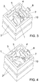
Figure 3 .- A view similar to that inFigure 2 is shown, but the device, once inserted, is rotated 90º. -
Figure 4 .- A view similar to that ofFigure 2 is shown, but the device is activated. It can be seen how using the device causes the rotation and release of the anchoring element. -
Figure 5 .- A detail of the set fromFigure 4 is shown from another point of view. -
Figure 6 .- A longitudinal view of the device at hand is shown in perspective. -
Figure 7 .- Finally, a view similar to that ofFigure 6 is shown, but with the device in the activated position with its plate acting as a lever. - In the figures outlined, it can be seen how the invention is designed to operate a locking mechanism that involves two locking elements (1) between two containers (2), which have at their corners mortising with elongated slots (3) aligned with three orthogonal planes, such that the locking elements (1) turn once inserted in the corresponding slots, so as to prevent misalignment between containers.
- In accordance with the invention, the device is planned to take the form of a body (4) with a cross-section corresponding to the cross-section of the elongated slots (3) whose middle area will feature a perimeter rabbet (6) with a height corresponding to the width of the elongated slots (3) so that this body, once inserted into the corresponding groove, can be rotated 90º, as shown in
Figures 2 and3 , with the rabbet's side walls (7) establishing the device's means of stabilization when activated. - The body (4) has a through-hole through which a rod (9) can be inserted. The rod's anterior extremity pushes a plate (5) acting as a lever, which articulates with that body (4) through a pivot axis (10).
- This plate (5) acting as a lever will be designed according to the appearance of the locking element (1) to be adapted to its surface so that when the rod (9) is moved axially, the plate will cause the rotation and release of that locking element (1).
- To this end, the rod (9) is then planned to be closed off in a cylindrical body (8) joined to said rod and threaded. It will thread into the device's main body by turning a wingnut, lever, screwdriver, etc. That way, the positioning of this rod can be adjusted and locked, as can the plate, in the position deemed appropriate.
Claims (3)
- st.- Device for the auxiliary operation of locking elements between shipping containers, characterized by a cross-section body (4) corresponding to the cross-section of the elongated slots (3) in the mortising that determine the means of locking containers together at their corners. The middle area of this body (4) has a perimeter rabbet (6) of a height corresponding to the width of these elongated slots (3) to enable their 90º rotation after insertion. The body (4) has a through-hole, through which a rod (9) may pass. The rod's anterior extremity offers a means to push a plate (5) as a lever, which is joined to that body (4) by a pivot axis (10). The configuration of this plate (5) corresponds to the design of the locking element (1) to move angularly.
- nd.- Device for the auxiliary operation of locking elements between shipping containers, according to claim 1, wherein the rod (9) is then closed in a cylindrical body (8) joined to said rod and threaded. It threads into the main body of the device as a means of stabilizing the rod (9) in the position deemed appropriate.
- rd.- Device for the auxiliary operation of locking elements between shipping containers, according to claim 1, wherein the device's body (4) may include at least one magnet or be magnetic itself.
Applications Claiming Priority (1)
| Application Number | Priority Date | Filing Date | Title |
|---|---|---|---|
| ES201930497A ES2797998B2 (en) | 2019-06-04 | 2019-06-04 | Device for the auxiliary actuation of lashing elements between maritime containers |
Publications (1)
| Publication Number | Publication Date |
|---|---|
| EP3747801A1 true EP3747801A1 (en) | 2020-12-09 |
Family
ID=70975665
Family Applications (1)
| Application Number | Title | Priority Date | Filing Date |
|---|---|---|---|
| EP20020255.4A Withdrawn EP3747801A1 (en) | 2019-06-04 | 2020-06-01 | Device for the auxiliary operation of locking elements between shipping containers |
Country Status (2)
| Country | Link |
|---|---|
| EP (1) | EP3747801A1 (en) |
| ES (1) | ES2797998B2 (en) |
Citations (4)
| Publication number | Priority date | Publication date | Assignee | Title |
|---|---|---|---|---|
| US3556456A (en) * | 1968-09-24 | 1971-01-19 | Einar O Lunde | Container fastener means |
| DE8402894U1 (en) * | 1984-02-02 | 1984-03-15 | Wader Willi Gmbh | Twist lock for connecting containers with two locking positions |
| EP0268415A2 (en) * | 1986-11-17 | 1988-05-25 | George Blair P.L.C. | Means for securing together containers |
| WO2019090395A1 (en) * | 2017-11-09 | 2019-05-16 | Modalinta Pte Limited | Twist lock recovery tool and system |
Family Cites Families (4)
| Publication number | Priority date | Publication date | Assignee | Title |
|---|---|---|---|---|
| JP2008511481A (en) * | 2004-08-30 | 2008-04-17 | エヌエスエル・エンジニアリング・プライベイト・リミテッド | Twist lock handling system |
| DE102010007675B3 (en) * | 2010-02-10 | 2011-06-30 | Kapelski, Rainer, 24401 | slot gripper |
| DE102011002518B3 (en) * | 2011-01-11 | 2012-05-31 | German Lashing Robert Böck GmbH | Locking device for securing container on board of ship, has magnet arranged at device such that rotating movement for external intervention of locking bodies is inhibited with corner fitting by interaction of magnet |
| JP6305010B2 (en) * | 2013-10-22 | 2018-04-04 | 山九株式会社 | Semi-auto locking container connector release jig |
-
2019
- 2019-06-04 ES ES201930497A patent/ES2797998B2/en active Active
-
2020
- 2020-06-01 EP EP20020255.4A patent/EP3747801A1/en not_active Withdrawn
Patent Citations (4)
| Publication number | Priority date | Publication date | Assignee | Title |
|---|---|---|---|---|
| US3556456A (en) * | 1968-09-24 | 1971-01-19 | Einar O Lunde | Container fastener means |
| DE8402894U1 (en) * | 1984-02-02 | 1984-03-15 | Wader Willi Gmbh | Twist lock for connecting containers with two locking positions |
| EP0268415A2 (en) * | 1986-11-17 | 1988-05-25 | George Blair P.L.C. | Means for securing together containers |
| WO2019090395A1 (en) * | 2017-11-09 | 2019-05-16 | Modalinta Pte Limited | Twist lock recovery tool and system |
Also Published As
| Publication number | Publication date |
|---|---|
| ES2797998A1 (en) | 2020-12-04 |
| ES2797998B2 (en) | 2021-06-01 |
Similar Documents
| Publication | Publication Date | Title |
|---|---|---|
| EP1437306B1 (en) | Locking mechanism of a container | |
| US4801232A (en) | Device for the removable fastening of a plate-shaped component onto a base with a T-groove open towards the component | |
| EP2254437B1 (en) | Suitcase for transport of tools or the like | |
| US7736108B1 (en) | Structural blind anchor bolt | |
| KR100460465B1 (en) | Auto Locking Apparatus of Container for Ship | |
| TWI461340B (en) | Coupling device | |
| WO2007120094A1 (en) | Safety lock for coupling devices and use of the coupling device for lashing of containers. | |
| US4051790A (en) | Vehicle safe | |
| US5937679A (en) | Trailer hitch lock | |
| US3363440A (en) | Automatically-retractive key holder | |
| US20080265597A1 (en) | Lifting Hook Device | |
| US1148410A (en) | Wrench-lock. | |
| US20150366299A1 (en) | Tie locking device | |
| US5314157A (en) | Elongatable support | |
| US5404736A (en) | Attachable vehicle hand brake lock assembly | |
| US1970463A (en) | Valve lock | |
| KR200448493Y1 (en) | Locking device for safe | |
| ES2797998B2 (en) | Device for the auxiliary actuation of lashing elements between maritime containers | |
| JP2003182683A (en) | Corn rock | |
| WO2019090395A1 (en) | Twist lock recovery tool and system | |
| SE520930C2 (en) | Safe tank cap against tearing | |
| DE1226452B (en) | Sliding latch clamping device on a door lock | |
| DE202016101450U1 (en) | Tensioner for tarpaulins | |
| KR200287585Y1 (en) | Auto Locking Apparatus of Container for Ship | |
| US1268852A (en) | Locking device. |
Legal Events
| Date | Code | Title | Description |
|---|---|---|---|
| PUAI | Public reference made under article 153(3) epc to a published international application that has entered the european phase |
Free format text: ORIGINAL CODE: 0009012 |
|
| STAA | Information on the status of an ep patent application or granted ep patent |
Free format text: STATUS: EXAMINATION IS IN PROGRESS |
|
| 17P | Request for examination filed |
Effective date: 20200602 |
|
| AK | Designated contracting states |
Kind code of ref document: A1 Designated state(s): AL AT BE BG CH CY CZ DE DK EE ES FI FR GB GR HR HU IE IS IT LI LT LU LV MC MK MT NL NO PL PT RO RS SE SI SK SM TR |
|
| AX | Request for extension of the european patent |
Extension state: BA ME |
|
| STAA | Information on the status of an ep patent application or granted ep patent |
Free format text: STATUS: THE APPLICATION IS DEEMED TO BE WITHDRAWN |
|
| 18D | Application deemed to be withdrawn |
Effective date: 20210119 |