EP3747774A1 - Latch and method for operating said latch - Google Patents
Latch and method for operating said latch Download PDFInfo
- Publication number
- EP3747774A1 EP3747774A1 EP19212395.8A EP19212395A EP3747774A1 EP 3747774 A1 EP3747774 A1 EP 3747774A1 EP 19212395 A EP19212395 A EP 19212395A EP 3747774 A1 EP3747774 A1 EP 3747774A1
- Authority
- EP
- European Patent Office
- Prior art keywords
- arm member
- latch
- housing portion
- keeper
- axis
- Prior art date
- Legal status (The legal status is an assumption and is not a legal conclusion. Google has not performed a legal analysis and makes no representation as to the accuracy of the status listed.)
- Granted
Links
Images





Classifications
-
- E—FIXED CONSTRUCTIONS
- E05—LOCKS; KEYS; WINDOW OR DOOR FITTINGS; SAFES
- E05C—BOLTS OR FASTENING DEVICES FOR WINGS, SPECIALLY FOR DOORS OR WINDOWS
- E05C19/00—Other devices specially designed for securing wings, e.g. with suction cups
- E05C19/10—Hook fastenings; Fastenings in which a link engages a fixed hook-like member
- E05C19/12—Hook fastenings; Fastenings in which a link engages a fixed hook-like member pivotally mounted around an axis
- E05C19/14—Hook fastenings; Fastenings in which a link engages a fixed hook-like member pivotally mounted around an axis with toggle action
- E05C19/145—Hook fastenings; Fastenings in which a link engages a fixed hook-like member pivotally mounted around an axis with toggle action flush
-
- B—PERFORMING OPERATIONS; TRANSPORTING
- B64—AIRCRAFT; AVIATION; COSMONAUTICS
- B64D—EQUIPMENT FOR FITTING IN OR TO AIRCRAFT; FLIGHT SUITS; PARACHUTES; ARRANGEMENT OR MOUNTING OF POWER PLANTS OR PROPULSION TRANSMISSIONS IN AIRCRAFT
- B64D29/00—Power-plant nacelles, fairings or cowlings
- B64D29/06—Attaching of nacelles, fairings or cowlings
-
- E—FIXED CONSTRUCTIONS
- E05—LOCKS; KEYS; WINDOW OR DOOR FITTINGS; SAFES
- E05B—LOCKS; ACCESSORIES THEREFOR; HANDCUFFS
- E05B1/00—Knobs or handles for wings; Knobs, handles, or press buttons for locks or latches on wings
-
- E—FIXED CONSTRUCTIONS
- E05—LOCKS; KEYS; WINDOW OR DOOR FITTINGS; SAFES
- E05B—LOCKS; ACCESSORIES THEREFOR; HANDCUFFS
- E05B41/00—Locks with visible indication as to whether the lock is locked or unlocked
-
- E—FIXED CONSTRUCTIONS
- E05—LOCKS; KEYS; WINDOW OR DOOR FITTINGS; SAFES
- E05B—LOCKS; ACCESSORIES THEREFOR; HANDCUFFS
- E05B63/00—Locks or fastenings with special structural characteristics
- E05B63/06—Locks or fastenings with special structural characteristics with lengthwise-adjustable bolts ; with adjustable backset, i.e. distance from door edge
-
- E—FIXED CONSTRUCTIONS
- E05—LOCKS; KEYS; WINDOW OR DOOR FITTINGS; SAFES
- E05C—BOLTS OR FASTENING DEVICES FOR WINGS, SPECIALLY FOR DOORS OR WINDOWS
- E05C19/00—Other devices specially designed for securing wings, e.g. with suction cups
- E05C19/10—Hook fastenings; Fastenings in which a link engages a fixed hook-like member
- E05C19/12—Hook fastenings; Fastenings in which a link engages a fixed hook-like member pivotally mounted around an axis
- E05C19/14—Hook fastenings; Fastenings in which a link engages a fixed hook-like member pivotally mounted around an axis with toggle action
-
- Y—GENERAL TAGGING OF NEW TECHNOLOGICAL DEVELOPMENTS; GENERAL TAGGING OF CROSS-SECTIONAL TECHNOLOGIES SPANNING OVER SEVERAL SECTIONS OF THE IPC; TECHNICAL SUBJECTS COVERED BY FORMER USPC CROSS-REFERENCE ART COLLECTIONS [XRACs] AND DIGESTS
- Y10—TECHNICAL SUBJECTS COVERED BY FORMER USPC
- Y10T—TECHNICAL SUBJECTS COVERED BY FORMER US CLASSIFICATION
- Y10T292/00—Closure fasteners
- Y10T292/20—Clamps
- Y10T292/205—Ring
- Y10T292/212—With expanding or contracting means
- Y10T292/216—Toggle lever
Definitions
- This disclosure relates generally to latches, and more particularly to latches for securing cowl doors.
- Modern aircraft gas turbine engines may include a nacelle configured to house the engine and other auxiliary systems.
- the nacelle may include one or more cowl sections associated with particular sections of the gas turbine engine.
- the nacelle may include a fan cowl or a thrust reverser cowl.
- the cowl sections may include one or more cowl doors configured to provide access to internal gas turbine engine components.
- the fan cowl may include two, hinged cowl doors to provide access to the fan case, FADEC and other components in proximity to the fan case.
- multiple latches may be used to secure the cowl doors together in a closed position.
- the latches are required to overcome the seal stiffness during the latch closing procedure.
- the latch handle capability and latch length is sized by the latch closing requirements, latch pre-load requirements, and seal compressibility. In these cases, a longer latch handle provides a greater mechanical advantage for the operator.
- latch handle positions engaged/disengaged
- latch handle positions it may be desirable for latch handle positions to be clearly visible during a pilot's preflight walk around. Accordingly, an improved latch which addresses one or more of the above concerns would find utility.
- a latch includes a latch housing including a first housing portion and a second housing portion separable from the first housing portion.
- the second housing portion includes a keeper.
- a first arm member is in rotational communication with the first housing portion.
- the first arm member is configured to rotate about a first axis between a first position and a second position.
- a second arm member is in rotational communication with the first arm member.
- the second arm member is configured to rotate with respect to the first arm member between a first position and a second position.
- a latch load pin is in rotational communication with the first arm member about a second axis.
- the latch load pin is configured to mate with the keeper with the first arm member in the first position.
- the second arm member in the first position is configured to be fixed relative to the first arm member as the first arm member rotates from the first position toward the second position.
- the first arm member includes a first end and a second end opposite the first end.
- the first arm member is coupled to the second arm member at the first end and the latch load pin at the second end.
- the first arm member is connected to the first housing portion with a connection member.
- the connection member is in rotational communication with the first arm member about the first axis and in rotational communication with the first housing portion about a third axis.
- the first axis is between the second axis and the second end of the first arm member along a length of the first arm member.
- first, second, and third axes are substantially parallel.
- the first arm member includes a stop configured to prevent rotation of the second arm member with respect to the first arm member past the first position in a direction of rotation away from the second position of the second arm member.
- the second arm member includes a lock configured to mate with the second housing portion when the second arm member is in the second position.
- the keeper is linearly adjustable between a first keeper position and a second keeper position with respect to the first housing portion.
- the first arm member has a first direction of rotation from the first position to the second position of the first arm member and the second arm member has a second direction of rotation from the first position to the second position of the second arm member and the first direction of rotation is opposite the second direction of rotation.
- the second arm member has a first end and a second end opposite the first end.
- the second arm member is in communication with the first arm member at the first end.
- the second end of the first arm member is a first distance from the first axis and the second end of the second arm member is a second distance from the first axis greater than the first distance.
- a nacelle for a gas turbine engine having an axial centerline includes a first cowl door rotatable about a first hinge, a second cowl door rotatable about a second hinge, and a latch configured to secure the first cowl door to the second cowl door when the latch is in an engaged condition.
- the latch includes a latch housing including a first housing portion and a second housing portion separable from the first housing portion. The first housing portion is mounted to the first cowl door and the second housing portion is mounted to the second cowl door. The second housing portion includes a keeper. A first arm member is in rotational communication with the first housing portion.
- the first arm member is configured to rotate about a first axis between a first position and a second position.
- a second arm member is in rotational communication with the first arm member.
- the second arm member is configured to rotate with respect to the first arm member between a first position and a second position.
- a latch load pin is in rotational communication with the first arm member about a second axis.
- the latch load pin is configured to mate with the keeper with the first arm member in the first position.
- the second arm member in the first position is configured to be fixed relative to the first arm member as the first arm member rotates from the first position toward the second position.
- the load pin is configured to pull the second housing portion towards the first housing portion as the first arm member rotates from the first position to the second position.
- an exterior surface of the second arm member forms a portion of an exterior surface of the nacelle when the latch is in the engaged condition.
- the second arm member includes a lock configured to mate with the second housing portion when the second arm member is in the second position.
- the lock is configured to mate with the second housing portion when the second arm member is in the second position and the load pin is mated with the keeper.
- the keeper is linearly adjustable between a first keeper position and a second keeper position with respect to the first housing portion.
- the second housing portion further includes an adjustment feature in communication with the keeper.
- the adjustment feature is rotatable between a first adjustment position and a second adjustment position and rotation of the adjustment feature from the first adjustment position to the second adjustment position moves the keeper from the first keeper position to the second keeper position.
- the adjustment feature is configured to be operated from both of a first position adjacent an exterior of the second housing portion and a second position adjacent an interior of the second housing portion.
- a method of engaging a cowl door latch is provided.
- a load pin is mated with a keeper.
- a first arm member is rotated about a first axis from a first position to a second position.
- the first arm member is in rotational communication with the load pin.
- a second arm member is rotated with respect to the first arm member from a first position to a second position.
- the second arm member is in rotational communication with the first arm member and the second arm member is fixed relative to the first arm member as the first arm member rotates from the first position toward the second position.
- connections are set forth between elements in the following description and in the drawings. It is noted that these connections are general and, unless specified otherwise, may be direct or indirect and that this specification is not intended to be limiting in this respect.
- a coupling between two or more entities may refer to a direct connection or an indirect connection.
- An indirect connection may incorporate one or more intervening entities.
- various method or process steps for embodiments of the present disclosure are described in the following description and drawings.
- a gas turbine engine 10 generally includes a fan section 12, a compressor section 14, a combustor section 16, a turbine section 18, and an exhaust section 20 disposed about an axial centerline 22.
- the gas turbine engine 10 further includes a nacelle 24 defining an exterior housing of the gas turbine engine 10 about the axial centerline 22.
- the nacelle may include an inlet 26, a fan cowl 28, and a thrust reverser 30.
- the nacelle 24 may be coupled to a pylon 32 which may mount the gas turbine engine 10 to an aircraft wing or fuselage (not shown).
- the fan cowl 28 and the thrust reverser 30 may include one or more cowl doors configured to provide access to internal portions of the gas turbine engine 10 for inspections and maintenance.
- the fan cowl 28 may include a first cowl door 34 and a second cowl door 36.
- Each of the first and second cowl doors 34, 36 may be rotatably mounted to the nacelle 24 by one or more hinges 38 (e.g., gooseneck hinges).
- hinges 38 e.g., gooseneck hinges.
- each of the first and second cowl doors 34, 36 may be mounted to the nacelle 24 at or proximate a top edge 40 by the hinges 38.
- the first and second cowl doors 34, 36 may contact one another at respective bottom edges 42 in the closed position.
- closed position will be used to refer to the cowl doors 34, 36 in a position so as to form a portion of a substantially continuous exterior surface of the nacelle 24 (e.g., the cowl doors 34, 36 are positioned for flight).
- the "open position” will be used to refer to the cowl doors 34, 36 in a position other than the closed position (e.g., the cowl doors 34, 36 are partially open, fully open, etc.). While the present disclosure will be explained with reference to cowl doors 34, 36 for the fan cowl 28, those of ordinary skill in the art will recognize that the present disclosure is also applicable to other cowl doors (e.g., thrust reverser cowl doors, core cowl doors, etc.), access panels, etc. configured to permit access to internal components of the gas turbine engine 10 or other equipment (e.g., industrial gas turbine engines, wind turbines, etc.).
- a latch 44 is illustrated in an engaged condition with the first and second cowl doors 34, 36 in the closed position.
- the cowl doors 34, 36 may include one or more additional latches which may be the same as or different than the latch 44.
- the latch 44 includes a latch housing 46.
- the latch housing 46 includes a first housing portion 48 mounted to the first cowl door 34 and a second housing portion 50 mounted to the second cowl door 36 such that the first and second housing portions 48, 50 may substantially contact one another with the first and second cowl doors 34, 36 in the closed position (minor gaps or misalignment, within design tolerances, may exist between the respective cowl doors 34, 36 and/or the respective housing portions 48, 50).
- the latch 44 includes a trigger 58 configured to effect, in part, a disengagement of the latch 44.
- the term “engaged” with respect to the latch 44 indicates that the latch 44 is in a final condition for securing the first and second cowl doors 34, 36 in the closed position for flight.
- the term “disengaged” will be used to refer to the latch 44 in a condition other than the engaged condition.
- Each of the first and second housing portions 48, 50 may include a mounting surface 52 configured to mate with a corresponding surface of the first and second cowl doors 34, 36, respectively.
- the latch housing 46 may have a flanged configuration including a plurality of apertures 54 configured to allow the first and second housing portions 48, 50 to be mounted to the respective first and second cowl doors 34, 36 by a corresponding plurality of fasteners.
- the first and second housing portions 48, 50 may be mounted to the respective first and second cowl doors 34, 36 by welding or any other suitable mounting method.
- the latch 44 is illustrated in the disengaged condition.
- the latch 44 includes a latch mechanism 56 configured to secure the first housing portion 48 to the second housing portion 50, and hence the first cowl door 34 to the second cowl door 36, when the cowl doors 34, 36 are in the closed position.
- the latch mechanism 56 is further configured to be retained within the latch housing 46 with the latch 44 in the engaged condition.
- the latch mechanism 56 includes a first arm member 60 having a first end 62 and a second end 64 opposite the first end 62.
- the first arm member 60 may include a first portion 66 and a second portion 68 spaced from the first portion 66.
- the first and second portions 66, 68 may each extend between the first end 62 and the second end 64 of the first arm member 60.
- connection members 70 may be in rotational communication with the first housing portion 48 about an axis 72.
- the connection members 70 may be in rotational communication with a pin 74 extending between a first internal surface 76 and a second internal surface 78 of the first housing portion 48.
- the connection members 70 may further be in rotational communication with the first arm member 60 about an axis 80.
- the first arm member 60 may be in rotational communication with the first housing portion 48, via the connection members 70, about the first axis 72.
- the first arm member 60 is configured to rotate about the axis 80 between a first position and a second position, wherein the second position corresponds to the engaged condition of the latch 44.
- the latch mechanism 56 includes a second arm member 82 having a first end 84 and a second end 86 opposite the first end.
- the second arm member 82 may include a cover portion 88 having first and second sides 90, 92 each extending between the first and second ends 84, 86.
- an exterior surface 94 of the cover portion 88 may form a portion of an exterior surface of the nacelle 24 when the latch 44 is in the engaged condition.
- the second arm member 82 may include transverse walls 96 spaced from one another and extending from the cover portion along each of the first and second sides 90, 92.
- the transverse walls 96 include an outer surface 98.
- the outer surface 98 of the transverse walls 96 may include a distinct coloration (e.g., brightly colored paint) with respect to the other components of the latch 44 or another distinguishing form of visual indication configured to indicate to a maintenance technician or other observer that the latch 44 is in a disengaged condition. Accordingly, the outer surface 98 of the transverse walls 96 may be visible to an observer when the latch 44 is in the disengaged condition but may not be visible to the observer when the latch 44 is in the engaged condition.
- a distinct coloration e.g., brightly colored paint
- the second arm member 82 is in rotational communication with the first arm member 60.
- the second arm member 82 may be in rotational communication with the first arm member 60 at a position proximate the second end 64 of the first arm member 60 and the first end 84 of the second arm member 82.
- the second arm member 82 may be in rotational communication with the first arm member 60 via links 100 rotatably mounted to one or both of the first arm member 60 and the second arm member 82.
- the second arm member 82 is configured to rotate, with respect to the first arm member 60, between a first position and a second position, wherein the second position corresponds to the engaged condition of the latch 44. As shown in FIG.
- the firm arm member 60 has a direction of rotation R1 (e.g., clockwise) about the axis 72 between the first position and the second position of the first arm member 60.
- the second arm member 82 may have a direction of rotation R2 which is opposite that of the direction of rotation R1 (e.g., counter-clockwise) between the first position and the second position of the second arm member 82.
- the second housing portion 50 includes a keeper 102.
- the keeper 102 may be configured as one or more hooks.
- the latch mechanism 56 includes a corresponding load pin 104 configured to mate with the keeper 102.
- the load pin 104 is in rotational communication with the first arm member 60 via an extension element 106.
- the extension element 106 has a first element end 108 rotatably mounted to the first arm member 60 about an axis 110.
- the extension element 106 may be rotatably mounted to the first arm member 60 proximate the first end 62 of the first arm member 60, for example, between the first and second portions 66, 68 of the first arm member 60.
- the extension element 106 has a second element end 112 coupled to the load pin 104.
- the second element end 112 may encompass a perimeter of the load pin 104, wherein the load pin has a length that is perpendicular to a length of the extension element 106.
- two or more of the axes 72, 80, 110 may be substantially parallel.
- the term "substantially" with regard to an angular relationship refers to the noted angular relationship +/- 5 degrees.
- the axis 72 may be disposed between the axis 110 and the second end 64 of the first arm member 60 along a length of the first arm member 60. Accordingly, rotation of the first arm member 60 in a direction of rotation R3 about the axis 72, in a direction opposite the direction of rotation R1, may cause the load pin 104 to move towards the keeper 102 of the second housing portion 50 thereby allowing an operator to mate the load pin 104 with the keeper 102.
- first arm member 60 may be defined by the position at which the load pin 104 has mated with the keeper 102 with no force yet applied to pull the second cowl door 36 towards the first cowl door 34.
- the second end 64 of the first arm member 60 may form a stop 114 configured to prevent rotation of the second arm member 82 past the first position of the second arm member 82 in a direction of rotation R4 away from the second position of the second arm member 82.
- the first position of the second arm member 82 may be defined by the position of the second arm member 82 with respect to the first arm member 60 where the second arm member 82 contacts the stop 114.
- the second arm member 82 may extend generally outward from the first arm member 60 with respect to the axis 72.
- the second arm member 82 in the first position of the second arm member 82 may be configured to be fixed relative to the first arm member 60 as the first arm member 60 rotates from the first position toward the second position of the first arm member 60.
- the second end 64 of the first arm member 60 in the first position has a radius 116 with respect to the axis 72 (i.e., a length between the second end 64 and the axis 72).
- the second end 86 of the second arm member 82 in the first position may have a radius 118, with respect to the axis 72, which is greater in length than the radius 116.
- the length of radius 118 may be greater than twice the length of the radius 116.
- rotation of the first arm member 60 from the first position to the second position of the first arm member 60 by applying a force to the second arm member 82 in the direction of rotation R4 may provide an operator with a greater mechanical advantage when pulling the second cowl door 36 towards the first cowl door 34 via the load pin 104 and the keeper 102.
- the latch mechanism 56 may be configured to be collapsible so as to fit entirely within the latch housing 46.
- the load pin 104 and the extension element 106 may fit between the portions 66, 68 of the first arm member 60 with the first arm member 60 in the second position.
- the first arm member 60 may fit between the transverse walls 96 of the second arm member 82 with the second arm member 82 in the second position.
- the second arm member 82 may include a lock 120 configured to mate with a retaining surface 122 of the second housing portion 50 when the latch 44 is in the engaged condition.
- the lock 120 may be engaged or disengaged from the retaining surface 122 (e.g., rotated into or out of contact with the retaining surface 122) by releasing or pressing the trigger 58, respectively.
- the lock 120 may prevent the latch 44 from inadvertently opening during gas turbine engine 10 operation, for example, as a result of vibration.
- the latch mechanism 56 may include a baulking feature configured to alert an operator of the latch 44 that the latch 44 has failed to engage.
- the extension element 106 may physically prevent one or both of the first arm member 60 from reaching the second position of the first arm member 60 and the second arm member 82 from reaching the second position of the second arm member 82.
- the lock 120 may be unable to engage with the retaining surface 122 as the operator attempts to place the latch 44 in the engaged condition.
- the outer surfaces 98 of the transverse walls 96 may remain visible to the operator, thereby alerting the operator that the latch 44 has failed to engage.
- the extension of the second arm member 82 from the first arm member 60 in combination with the distinguishing outer surfaces 98, may further indicate a disengaged condition of the latch 44 by extending more prominently from the latch 44.
- the second arm member 82 may include a hook 124 disposed at the second end 86.
- the hook 124 may be configured to engage the pin 74 as the second arm member 82 is rotated to the second position. Accordingly, the combination of the lock 120 and the hook 124 may further prevent the latch 44 from inadvertently opening during gas turbine engine 10 operation, for example, as a result of vibration.
- the second housing portion 50 includes an adjustment feature 126 configured to linearly adjust the position of the keeper 102 relative to the load pin 104.
- the adjustment feature 126 may be threadably engaged with the second housing portion 50. Accordingly, rotation of the adjustment feature 126 in a first direction may cause the keeper 102 to move in a direction towards the load pin 104. Conversely, rotation of the adjustment feature 126 in a second direction, opposite the first direction, may cause the keeper 102 to move in a direction away from the load pin 104.
- the adjustment feature 126 may be used to adjust the position of the keeper 102 (i.e., "rigging" the latch 44) with respect to the load pin 104 in order to, for example, adjust the preload of the latch 44 and/or to maintain an efficient aerodynamic gap between the closed cowl doors 34, 36. Where respective first and second cowl doors 34, 36 (see FIGS. 2A and 2B ) require two or more latches, the adjustment feature 126 of the latch 44 may be adjusted to balance the load between the two or more latches. In some embodiments, the adjustment feature 126 may be accessed from a position adjacent an interior of the second housing portion 50 (see, e.g., FIG.
- the adjustment feature 126 may be operated without opening the first and second cowl doors 34, 36 (e.g., from the position adjacent the exterior of the second housing portion 50).
- FIGS. 8A-G illustrate a corresponding sequence for engaging the latch 44.
- the load pin 104 is mated with the keeper 102 (see, e.g., FIGS. 8A and 8B ).
- the first arm member 60 is rotated about the first axis 72 from the first position to the second position (see, e.g., FIGS. 8B-D ). Rotation of the first arm member 60 from the first position to the second position may be effected by applying a force to the second end 86 of the second arm member 82 in the first position.
- step 203 the second arm member 82 is rotated from the first position toward the second position (see, e.g., FIGS. 8E and 8F ).
- step 204 the hook 124 is engaged with the pin 74 (see, e.g., FIGS. 8E and 8F ).
- step 205 the lock 120 is engaged with the retaining surface 122 (not shown, see FIG. 7B ), thereby placing the latch 44 in the engaged condition (see, e.g., FIGS. 8F and 8G )
- FIGS. 10A-G illustrate a corresponding sequence for disengaging the latch 44.
- the trigger 58 is depressed causing the lock 120 (not shown, see FIG. 6 ) to rotate out of engagement with the retaining surface 122 (not shown, see FIG. 7B ) (see, e.g., FIG. 10A ).
- the first arm member 60 is rotated from the second position toward the first position (see, e.g., FIGS. 10B-10E ).
- the second arm member 82 is rotated from the second position toward the first position (see, e.g., FIGS.
- step 304 the load pin 104 is disengaged from the keeper 102 (see, e.g., FIGS. 10D-10F ).
- step 305 the first and second housing portions 48, 50 are separated thereby opening the first and second cowl doors 34, 36 (see, e.g., FIG. 10G ).
Landscapes
- Engineering & Computer Science (AREA)
- Mechanical Engineering (AREA)
- Aviation & Aerospace Engineering (AREA)
- Structural Engineering (AREA)
- Lock And Its Accessories (AREA)
- Superstructure Of Vehicle (AREA)
- Wind Motors (AREA)
Abstract
Description
- This disclosure relates generally to latches, and more particularly to latches for securing cowl doors.
- Modern aircraft gas turbine engines may include a nacelle configured to house the engine and other auxiliary systems. The nacelle may include one or more cowl sections associated with particular sections of the gas turbine engine. For example, the nacelle may include a fan cowl or a thrust reverser cowl. The cowl sections may include one or more cowl doors configured to provide access to internal gas turbine engine components. For example, the fan cowl may include two, hinged cowl doors to provide access to the fan case, FADEC and other components in proximity to the fan case.
- To provide an effective cowl load path and safety redundancy, multiple latches may be used to secure the cowl doors together in a closed position. In cases where aerodynamic or fire seals are required between the cowl doors, the latches are required to overcome the seal stiffness during the latch closing procedure. In many cases, the latch handle capability and latch length is sized by the latch closing requirements, latch pre-load requirements, and seal compressibility. In these cases, a longer latch handle provides a greater mechanical advantage for the operator.
- Further, growing concern over inadvertent opening of fan cowls during flight has driven additional requirements regarding visibility of latch handle positions (engaged/disengaged). For example, it may be desirable for latch handle positions to be clearly visible during a pilot's preflight walk around. Accordingly, an improved latch which addresses one or more of the above concerns would find utility.
- According to an embodiment of the present disclosure, a latch includes a latch housing including a first housing portion and a second housing portion separable from the first housing portion. The second housing portion includes a keeper. A first arm member is in rotational communication with the first housing portion. The first arm member is configured to rotate about a first axis between a first position and a second position. A second arm member is in rotational communication with the first arm member. The second arm member is configured to rotate with respect to the first arm member between a first position and a second position. A latch load pin is in rotational communication with the first arm member about a second axis. The latch load pin is configured to mate with the keeper with the first arm member in the first position. The second arm member in the first position is configured to be fixed relative to the first arm member as the first arm member rotates from the first position toward the second position.
- In the alternative or additionally thereto, in the foregoing embodiment, the first arm member includes a first end and a second end opposite the first end. The first arm member is coupled to the second arm member at the first end and the latch load pin at the second end.
- In the alternative or additionally thereto, in the foregoing embodiment, the first arm member is connected to the first housing portion with a connection member. The connection member is in rotational communication with the first arm member about the first axis and in rotational communication with the first housing portion about a third axis.
- In the alternative or additionally thereto, in the foregoing embodiment, the first axis is between the second axis and the second end of the first arm member along a length of the first arm member.
- In the alternative or additionally thereto, in the foregoing embodiment, the first, second, and third axes are substantially parallel.
- In the alternative or additionally thereto, in the foregoing embodiment, the first arm member includes a stop configured to prevent rotation of the second arm member with respect to the first arm member past the first position in a direction of rotation away from the second position of the second arm member.
- In the alternative or additionally thereto, in the foregoing embodiment, the second arm member includes a lock configured to mate with the second housing portion when the second arm member is in the second position.
- In the alternative or additionally thereto, in the foregoing embodiment, the keeper is linearly adjustable between a first keeper position and a second keeper position with respect to the first housing portion.
- In the alternative or additionally thereto, in the foregoing embodiment, the first arm member has a first direction of rotation from the first position to the second position of the first arm member and the second arm member has a second direction of rotation from the first position to the second position of the second arm member and the first direction of rotation is opposite the second direction of rotation.
- In the alternative or additionally thereto, in the foregoing embodiment, the second arm member has a first end and a second end opposite the first end. The second arm member is in communication with the first arm member at the first end.
- In the alternative or additionally thereto, in the foregoing embodiment, with the first arm member in the first position and the second arm member in the first position, the second end of the first arm member is a first distance from the first axis and the second end of the second arm member is a second distance from the first axis greater than the first distance.
- According to another embodiment of the present disclosure, a nacelle for a gas turbine engine having an axial centerline is disclosed. The nacelle includes a first cowl door rotatable about a first hinge, a second cowl door rotatable about a second hinge, and a latch configured to secure the first cowl door to the second cowl door when the latch is in an engaged condition. The latch includes a latch housing including a first housing portion and a second housing portion separable from the first housing portion. The first housing portion is mounted to the first cowl door and the second housing portion is mounted to the second cowl door. The second housing portion includes a keeper. A first arm member is in rotational communication with the first housing portion. The first arm member is configured to rotate about a first axis between a first position and a second position. A second arm member is in rotational communication with the first arm member. The second arm member is configured to rotate with respect to the first arm member between a first position and a second position. A latch load pin is in rotational communication with the first arm member about a second axis. The latch load pin is configured to mate with the keeper with the first arm member in the first position. The second arm member in the first position is configured to be fixed relative to the first arm member as the first arm member rotates from the first position toward the second position.
- In the alternative or additionally thereto, in the foregoing embodiment, the load pin is configured to pull the second housing portion towards the first housing portion as the first arm member rotates from the first position to the second position.
- In the alternative or additionally thereto, in the foregoing embodiment, an exterior surface of the second arm member forms a portion of an exterior surface of the nacelle when the latch is in the engaged condition.
- In the alternative or additionally thereto, in the foregoing embodiment, the second arm member includes a lock configured to mate with the second housing portion when the second arm member is in the second position.
- In the alternative or additionally thereto, in the foregoing embodiment, the lock is configured to mate with the second housing portion when the second arm member is in the second position and the load pin is mated with the keeper.
- In the alternative or additionally thereto, in the foregoing embodiment, the keeper is linearly adjustable between a first keeper position and a second keeper position with respect to the first housing portion.
- In the alternative or additionally thereto, in the foregoing embodiment, the second housing portion further includes an adjustment feature in communication with the keeper. The adjustment feature is rotatable between a first adjustment position and a second adjustment position and rotation of the adjustment feature from the first adjustment position to the second adjustment position moves the keeper from the first keeper position to the second keeper position.
- In the alternative or additionally thereto, in the foregoing embodiment, the adjustment feature is configured to be operated from both of a first position adjacent an exterior of the second housing portion and a second position adjacent an interior of the second housing portion.
- According to another embodiment of the present disclosure, a method of engaging a cowl door latch is provided. A load pin is mated with a keeper. A first arm member is rotated about a first axis from a first position to a second position. The first arm member is in rotational communication with the load pin. A second arm member is rotated with respect to the first arm member from a first position to a second position. The second arm member is in rotational communication with the first arm member and the second arm member is fixed relative to the first arm member as the first arm member rotates from the first position toward the second position.
- The present disclosure, and all its aspects, embodiments and advantages associated therewith will become more readily apparent in view of the detailed description provided below, including the accompanying drawings.
-
-
FIG. 1 illustrates a side, cross-sectional view of a gas turbine engine. -
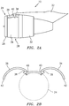
FIG. 2A illustrates a side view of a gas turbine engine nacelle. -
FIG. 2B illustrates a front view of the gas turbine engine nacelle ofFIG. 2A . -
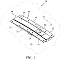
FIG. 3 illustrates a perspective view of a latch in an engaged condition. -
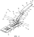
FIG. 4 illustrates a perspective view of the latch ofFIG. 3 in a disengaged condition. -
FIG. 5 illustrates a perspective view of the latch ofFIG. 3 in a disengaged condition. -
FIG. 6 illustrates a cross-sectional side view of the latch ofFIG. 3 in a disengaged condition. -
FIG. 7A illustrates an exterior view of a portion of the latch ofFIG. 3 . -
FIG. 7B illustrates an interior view of a portion of the latch ofFIG. 3 . -
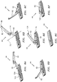
FIGS. 8A-G illustrate an exemplary sequence for engaging the latch ofFIG. 3 . -
FIG. 9 is a flowchart depicting a method for engaging a cowl door latch. -
FIGS. 10A-G illustrate an exemplary sequence for disengaging the latch ofFIG. 3 . -
FIG. 11 is a flowchart depicting a method for disengaging a cowl door latch. - It is noted that various connections are set forth between elements in the following description and in the drawings. It is noted that these connections are general and, unless specified otherwise, may be direct or indirect and that this specification is not intended to be limiting in this respect. A coupling between two or more entities may refer to a direct connection or an indirect connection. An indirect connection may incorporate one or more intervening entities. It is further noted that various method or process steps for embodiments of the present disclosure are described in the following description and drawings.
- Referring to
FIGS. 1 ,2A, and 2B , agas turbine engine 10 generally includes afan section 12, acompressor section 14, acombustor section 16, aturbine section 18, and anexhaust section 20 disposed about anaxial centerline 22. Thegas turbine engine 10 further includes anacelle 24 defining an exterior housing of thegas turbine engine 10 about theaxial centerline 22. The nacelle may include aninlet 26, afan cowl 28, and athrust reverser 30. Thenacelle 24 may be coupled to apylon 32 which may mount thegas turbine engine 10 to an aircraft wing or fuselage (not shown). - The
fan cowl 28 and thethrust reverser 30 may include one or more cowl doors configured to provide access to internal portions of thegas turbine engine 10 for inspections and maintenance. For example, thefan cowl 28 may include afirst cowl door 34 and asecond cowl door 36. Each of the first andsecond cowl doors nacelle 24 by one or more hinges 38 (e.g., gooseneck hinges). For example, as shown inFIGS. 2A and 2B , each of the first andsecond cowl doors nacelle 24 at or proximate atop edge 40 by thehinges 38. The first andsecond cowl doors bottom edges 42 in the closed position. - As used herein, "closed position" will be used to refer to the
cowl doors cowl doors cowl doors cowl doors cowl doors fan cowl 28, those of ordinary skill in the art will recognize that the present disclosure is also applicable to other cowl doors (e.g., thrust reverser cowl doors, core cowl doors, etc.), access panels, etc. configured to permit access to internal components of thegas turbine engine 10 or other equipment (e.g., industrial gas turbine engines, wind turbines, etc.). - Referring to
FIG. 3 , alatch 44 is illustrated in an engaged condition with the first andsecond cowl doors cowl doors latch 44. Thelatch 44 includes alatch housing 46. Thelatch housing 46 includes afirst housing portion 48 mounted to thefirst cowl door 34 and asecond housing portion 50 mounted to thesecond cowl door 36 such that the first andsecond housing portions second cowl doors respective cowl doors respective housing portions 48, 50). The first andsecond housing portions latch 44 includes atrigger 58 configured to effect, in part, a disengagement of thelatch 44. As used herein, the term "engaged" with respect to thelatch 44 indicates that thelatch 44 is in a final condition for securing the first andsecond cowl doors latch 44 in a condition other than the engaged condition. - Each of the first and
second housing portions surface 52 configured to mate with a corresponding surface of the first andsecond cowl doors latch housing 46 may have a flanged configuration including a plurality ofapertures 54 configured to allow the first andsecond housing portions second cowl doors second housing portions second cowl doors - Referring to
FIGS. 4 and5 , thelatch 44 is illustrated in the disengaged condition. Thelatch 44 includes alatch mechanism 56 configured to secure thefirst housing portion 48 to thesecond housing portion 50, and hence thefirst cowl door 34 to thesecond cowl door 36, when thecowl doors latch mechanism 56 is further configured to be retained within thelatch housing 46 with thelatch 44 in the engaged condition. Thelatch mechanism 56 includes afirst arm member 60 having afirst end 62 and asecond end 64 opposite thefirst end 62. Thefirst arm member 60 may include afirst portion 66 and asecond portion 68 spaced from thefirst portion 66. The first andsecond portions first end 62 and thesecond end 64 of thefirst arm member 60. - Each of the first and
second portions first housing portion 48 by arespective connection member 70. Theconnection members 70 may be in rotational communication with thefirst housing portion 48 about anaxis 72. For example, theconnection members 70 may be in rotational communication with apin 74 extending between a firstinternal surface 76 and a secondinternal surface 78 of thefirst housing portion 48. Theconnection members 70 may further be in rotational communication with thefirst arm member 60 about anaxis 80. Accordingly, thefirst arm member 60 may be in rotational communication with thefirst housing portion 48, via theconnection members 70, about thefirst axis 72. Thefirst arm member 60 is configured to rotate about theaxis 80 between a first position and a second position, wherein the second position corresponds to the engaged condition of thelatch 44. - The
latch mechanism 56 includes asecond arm member 82 having afirst end 84 and asecond end 86 opposite the first end. Thesecond arm member 82 may include acover portion 88 having first andsecond sides FIG. 3 , anexterior surface 94 of thecover portion 88 may form a portion of an exterior surface of thenacelle 24 when thelatch 44 is in the engaged condition. Thesecond arm member 82 may includetransverse walls 96 spaced from one another and extending from the cover portion along each of the first andsecond sides transverse walls 96 include anouter surface 98. In some embodiments, theouter surface 98 of thetransverse walls 96 may include a distinct coloration (e.g., brightly colored paint) with respect to the other components of thelatch 44 or another distinguishing form of visual indication configured to indicate to a maintenance technician or other observer that thelatch 44 is in a disengaged condition. Accordingly, theouter surface 98 of thetransverse walls 96 may be visible to an observer when thelatch 44 is in the disengaged condition but may not be visible to the observer when thelatch 44 is in the engaged condition. - The
second arm member 82 is in rotational communication with thefirst arm member 60. For example, thesecond arm member 82 may be in rotational communication with thefirst arm member 60 at a position proximate thesecond end 64 of thefirst arm member 60 and thefirst end 84 of thesecond arm member 82. Thesecond arm member 82 may be in rotational communication with thefirst arm member 60 vialinks 100 rotatably mounted to one or both of thefirst arm member 60 and thesecond arm member 82. Thesecond arm member 82 is configured to rotate, with respect to thefirst arm member 60, between a first position and a second position, wherein the second position corresponds to the engaged condition of thelatch 44. As shown inFIG. 5 , thefirm arm member 60 has a direction of rotation R1 (e.g., clockwise) about theaxis 72 between the first position and the second position of thefirst arm member 60. Thesecond arm member 82 may have a direction of rotation R2 which is opposite that of the direction of rotation R1 (e.g., counter-clockwise) between the first position and the second position of thesecond arm member 82. - The
second housing portion 50 includes akeeper 102. Thekeeper 102 may be configured as one or more hooks. Thelatch mechanism 56 includes acorresponding load pin 104 configured to mate with thekeeper 102. Theload pin 104 is in rotational communication with thefirst arm member 60 via anextension element 106. Theextension element 106 has afirst element end 108 rotatably mounted to thefirst arm member 60 about anaxis 110. Theextension element 106 may be rotatably mounted to thefirst arm member 60 proximate thefirst end 62 of thefirst arm member 60, for example, between the first andsecond portions first arm member 60. Theextension element 106 has asecond element end 112 coupled to theload pin 104. In some embodiments, thesecond element end 112 may encompass a perimeter of theload pin 104, wherein the load pin has a length that is perpendicular to a length of theextension element 106. In some embodiments, two or more of theaxes - The
axis 72 may be disposed between theaxis 110 and thesecond end 64 of thefirst arm member 60 along a length of thefirst arm member 60. Accordingly, rotation of thefirst arm member 60 in a direction of rotation R3 about theaxis 72, in a direction opposite the direction of rotation R1, may cause theload pin 104 to move towards thekeeper 102 of thesecond housing portion 50 thereby allowing an operator to mate theload pin 104 with thekeeper 102. Once theload pin 104 and thekeeper 102 are mated, rotation of thefirst arm member 60 in the direction of rotation R1 may cause theload pin 104 to pull thesecond housing portion 50, via thekeeper 102, towards thefirst housing portion 48 and, hence, pull thesecond cowl door 36 towards thefirst cowl door 34. The first position of thefirst arm member 60 may be defined by the position at which theload pin 104 has mated with thekeeper 102 with no force yet applied to pull thesecond cowl door 36 towards thefirst cowl door 34. - The
second end 64 of thefirst arm member 60 may form astop 114 configured to prevent rotation of thesecond arm member 82 past the first position of thesecond arm member 82 in a direction of rotation R4 away from the second position of thesecond arm member 82. The first position of thesecond arm member 82 may be defined by the position of thesecond arm member 82 with respect to thefirst arm member 60 where thesecond arm member 82 contacts thestop 114. Thus, thesecond arm member 82 may extend generally outward from thefirst arm member 60 with respect to theaxis 72. An operator applying a force to thesecond end 86 of thesecond arm member 82, to rotate thesecond arm member 82 in the direction of rotation R4 would cause thesecond arm member 82 to encounter thestop 114, thereby causing thefirst arm member 60 to rotate in the direction of rotation R1, for example, from the first position to the second position of thefirst arm member 60. Accordingly, thesecond arm member 82 in the first position of thesecond arm member 82 may be configured to be fixed relative to thefirst arm member 60 as thefirst arm member 60 rotates from the first position toward the second position of thefirst arm member 60. - The
second end 64 of thefirst arm member 60 in the first position has aradius 116 with respect to the axis 72 (i.e., a length between thesecond end 64 and the axis 72). Thesecond end 86 of thesecond arm member 82 in the first position may have aradius 118, with respect to theaxis 72, which is greater in length than theradius 116. In some embodiments, the length ofradius 118 may be greater than twice the length of theradius 116. Accordingly, as one of ordinary skill in the art will appreciate, rotation of thefirst arm member 60 from the first position to the second position of thefirst arm member 60 by applying a force to thesecond arm member 82 in the direction of rotation R4 may provide an operator with a greater mechanical advantage when pulling thesecond cowl door 36 towards thefirst cowl door 34 via theload pin 104 and thekeeper 102. - Referring to
FIGS. 3 ,4 , and6 , thelatch mechanism 56 may be configured to be collapsible so as to fit entirely within thelatch housing 46. For example, theload pin 104 and theextension element 106 may fit between theportions first arm member 60 with thefirst arm member 60 in the second position. Similarly, thefirst arm member 60 may fit between thetransverse walls 96 of thesecond arm member 82 with thesecond arm member 82 in the second position. - Referring to
FIGS 5 ,6 , and7B , in some embodiments, thesecond arm member 82 may include alock 120 configured to mate with a retainingsurface 122 of thesecond housing portion 50 when thelatch 44 is in the engaged condition. Thelock 120 may be engaged or disengaged from the retaining surface 122 (e.g., rotated into or out of contact with the retaining surface 122) by releasing or pressing thetrigger 58, respectively. Thelock 120 may prevent thelatch 44 from inadvertently opening duringgas turbine engine 10 operation, for example, as a result of vibration. - In some embodiments, the
latch mechanism 56 may include a baulking feature configured to alert an operator of thelatch 44 that thelatch 44 has failed to engage. For example, if theload pin 104 has failed to mate with thekeeper 102, theextension element 106 may physically prevent one or both of thefirst arm member 60 from reaching the second position of thefirst arm member 60 and thesecond arm member 82 from reaching the second position of thesecond arm member 82. Thus, thelock 120 may be unable to engage with the retainingsurface 122 as the operator attempts to place thelatch 44 in the engaged condition. Further, theouter surfaces 98 of thetransverse walls 96 may remain visible to the operator, thereby alerting the operator that thelatch 44 has failed to engage. The extension of thesecond arm member 82 from thefirst arm member 60, in combination with the distinguishingouter surfaces 98, may further indicate a disengaged condition of thelatch 44 by extending more prominently from thelatch 44. - Referring to
FIGS. 4 and5 , in some embodiments, thesecond arm member 82 may include ahook 124 disposed at thesecond end 86. Thehook 124 may be configured to engage thepin 74 as thesecond arm member 82 is rotated to the second position. Accordingly, the combination of thelock 120 and thehook 124 may further prevent thelatch 44 from inadvertently opening duringgas turbine engine 10 operation, for example, as a result of vibration. - Referring to
FIGS. 6 ,7A , and7B , in some embodiments, thesecond housing portion 50 includes anadjustment feature 126 configured to linearly adjust the position of thekeeper 102 relative to theload pin 104. Theadjustment feature 126 may be threadably engaged with thesecond housing portion 50. Accordingly, rotation of theadjustment feature 126 in a first direction may cause thekeeper 102 to move in a direction towards theload pin 104. Conversely, rotation of theadjustment feature 126 in a second direction, opposite the first direction, may cause thekeeper 102 to move in a direction away from theload pin 104. Theadjustment feature 126 may be used to adjust the position of the keeper 102 (i.e., "rigging" the latch 44) with respect to theload pin 104 in order to, for example, adjust the preload of thelatch 44 and/or to maintain an efficient aerodynamic gap between theclosed cowl doors second cowl doors 34, 36 (seeFIGS. 2A and 2B ) require two or more latches, theadjustment feature 126 of thelatch 44 may be adjusted to balance the load between the two or more latches. In some embodiments, theadjustment feature 126 may be accessed from a position adjacent an interior of the second housing portion 50 (see, e.g.,FIG. 7B ) and/or a position adjacent an exterior of the second housing portion 50 (see, e.g.,FIG. 7A ). In some embodiments, theadjustment feature 126 may be operated without opening the first andsecond cowl doors 34, 36 (e.g., from the position adjacent the exterior of the second housing portion 50). - Referring to
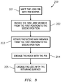
FIG. 9 , anexemplary method 200 for engaging a latch, such as thelatch 44, is shown.FIGS. 8A-G illustrate a corresponding sequence for engaging thelatch 44. Instep 201, theload pin 104 is mated with the keeper 102 (see, e.g.,FIGS. 8A and 8B ). Instep 202, thefirst arm member 60 is rotated about thefirst axis 72 from the first position to the second position (see, e.g.,FIGS. 8B-D ). Rotation of thefirst arm member 60 from the first position to the second position may be effected by applying a force to thesecond end 86 of thesecond arm member 82 in the first position. The corresponding interaction between thesecond arm member 82 and thestop 114 causes thefirst arm member 60 to rotate from the first position to the second position. Rotation of thefirst arm member 60 from the first position to the second position thereby pulls thesecond cowl door 36 towards the first cowl door 34 (seeFIGS. 2A and 2B ). Instep 203, thesecond arm member 82 is rotated from the first position toward the second position (see, e.g.,FIGS. 8E and 8F ). Instep 204, thehook 124 is engaged with the pin 74 (see, e.g.,FIGS. 8E and 8F ). Instep 205, thelock 120 is engaged with the retaining surface 122 (not shown, seeFIG. 7B ), thereby placing thelatch 44 in the engaged condition (see, e.g.,FIGS. 8F and 8G ) - Referring to
FIG. 11 , anexemplary method 300 for disengaging a latch, such as thelatch 44, is shown.FIGS. 10A-G illustrate a corresponding sequence for disengaging thelatch 44. Instep 301, thetrigger 58 is depressed causing the lock 120 (not shown, seeFIG. 6 ) to rotate out of engagement with the retaining surface 122 (not shown, seeFIG. 7B ) (see, e.g.,FIG. 10A ). Instep 302, thefirst arm member 60 is rotated from the second position toward the first position (see, e.g.,FIGS. 10B-10E ). Instep 303, thesecond arm member 82 is rotated from the second position toward the first position (see, e.g.,FIGS. 10D and 10E ). Instep 304, theload pin 104 is disengaged from the keeper 102 (see, e.g.,FIGS. 10D-10F ). Instep 305, the first andsecond housing portions second cowl doors 34, 36 (see, e.g.,FIG. 10G ). - While various aspects of the present disclosure have been disclosed, it will be apparent to those of ordinary skill in the art that many more embodiments and implementations are possible within the scope of the present disclosure. For example, the present disclosure as described herein includes several aspects and embodiments that include particular features. Although these particular features may be described individually, it is within the scope of the present disclosure that some or all of these features may be combined with any one of the aspects and remain within the scope of the present disclosure. Accordingly, the present disclosure is not to be restricted except in light of the attached claims and their equivalents.
Claims (15)
- A latch comprising:a latch housing comprising a first housing portion and a second housing portion separable from the first housing portion, the second housing portion comprising a keeper;a first arm member in rotational communication with the first housing portion, the first arm member configured to rotate about a first axis between a first position and a second position;a second arm member in rotational communication with the first arm member, the second arm member configured to rotate with respect to the first arm member between a first position and a second position; anda latch load pin in rotational communication with the first arm member about a second axis, the latch load pin configured to mate with the keeper with the first arm member in the first position;wherein the second arm member in the first position is configured to be fixed relative to the first arm member as the first arm member rotates from the first position toward the second position.
- The latch of claim 1, wherein the first arm member includes a first end and a second end opposite the first end, the first arm member coupled to the second arm member at the first end and the latch load pin at the second end.
- The latch of claim 1 or 2, wherein the first arm member is connected to the first housing portion with a connection member, the connection member in rotational communication with the first arm member about the first axis and in rotational communication with the first housing portion about a third axis.
- The latch of claim 3, wherein the first axis is between the second axis and the second end of the first arm member along a length of the first arm member.
- The latch of claim 4, wherein the first, second, and third axes are substantially parallel.
- The latch of any preceding claim, wherein the first arm member includes a stop configured to prevent rotation of the second arm member with respect to the first arm member past the first position in a direction of rotation away from the second position of the second arm member.
- The latch of any preceding claim, wherein the first arm member has a first direction of rotation from the first position to the second position of the first arm member and the second arm member has a second direction of rotation from the first position to the second position of the second arm member and the first direction of rotation is opposite the second direction of rotation.
- The latch of any preceding claim, wherein the second arm member has a first end and a second end opposite the first end, the second arm member in communication with the first arm member at the first end.
- The latch of any preceding claim, wherein with the first arm member in the first position and the second arm member in the first position, the second end of the first arm member is a first distance from the first axis and the second end of the second arm member is a second distance from the first axis greater than the first distance.
- A nacelle for a gas turbine engine having an axial centerline, the nacelle comprising:a first cowl door rotatable about a first hinge;a second cowl door rotatable about a second hinge; anda latch as claimed in any preceding claim and configured to secure the first cowl door to the second cowl door when the latch is in an engaged condition, the first housing portion mounted to the first cowl door and the second housing portion mounted to the second cowl door, wherein an exterior surface of the second arm member optionally forms a portion of an exterior surface of the nacelle when the latch is in the engaged condition.
- The nacelle of claim 10, wherein the load pin is configured to pull the second housing portion towards the first housing portion as the first arm member rotates from the first position to the second position.
- The nacelle of claim 10 or 11, wherein the second housing portion further comprises an adjustment feature in communication with the keeper, wherein the adjustment feature is rotatable between a first adjustment position and a second adjustment position and rotation of the adjustment feature from the first adjustment position to the second adjustment position moves the keeper from the first keeper position to the second keeper position, wherein the adjustment feature is optionally configured to be operated from both of a first position adjacent an exterior of the second housing portion and a second position adjacent an interior of the second housing portion.
- The latch or nacelle of any preceding claim, wherein the second arm member includes a lock configured to mate with the second housing portion when the second arm member is in the second position, wherein the lock is optionally configured to mate with the second housing portion when the second arm member is in the second position and the load pin is mated with the keeper.
- The latch or nacelle of any preceding claim, wherein the keeper is linearly adjustable between a first keeper position and a second keeper position with respect to the first housing portion.
- A method of engaging a cowl door latch, the method comprising:mating a load pin with a keeper;rotating a first arm member about a first axis from a first position to a second position, the first arm member in rotational communication with the load pin,rotating a second arm member with respect to the first arm member from a first position to a second position;wherein the second arm member is in rotational communication with the first arm member and the second arm member is fixed relative to the first arm member as the first arm member rotates from the first position toward the second position.
Applications Claiming Priority (1)
| Application Number | Priority Date | Filing Date | Title |
|---|---|---|---|
| US16/430,979 US11326378B2 (en) | 2019-06-04 | 2019-06-04 | Latch and method for operating said latch |
Publications (2)
| Publication Number | Publication Date |
|---|---|
| EP3747774A1 true EP3747774A1 (en) | 2020-12-09 |
| EP3747774B1 EP3747774B1 (en) | 2022-11-23 |
Family
ID=68732829
Family Applications (1)
| Application Number | Title | Priority Date | Filing Date |
|---|---|---|---|
| EP19212395.8A Active EP3747774B1 (en) | 2019-06-04 | 2019-11-29 | Latch and method for operating said latch |
Country Status (2)
| Country | Link |
|---|---|
| US (1) | US11326378B2 (en) |
| EP (1) | EP3747774B1 (en) |
Families Citing this family (1)
| Publication number | Priority date | Publication date | Assignee | Title |
|---|---|---|---|---|
| EP4331997A1 (en) | 2022-09-05 | 2024-03-06 | Rohr, Inc. | Long throw latch |
Citations (5)
| Publication number | Priority date | Publication date | Assignee | Title |
|---|---|---|---|---|
| US2896751A (en) * | 1956-11-16 | 1959-07-28 | Clark Hartwell | Toggle bolt latch |
| US2904141A (en) * | 1957-04-22 | 1959-09-15 | Clark Hartwell | Adjustable hook latch |
| EP1091059A2 (en) * | 1999-10-05 | 2001-04-11 | Hartwell Corporation | Latch with sensor providing visual indication of the latch position |
| US20160347465A1 (en) * | 2015-05-29 | 2016-12-01 | The Boeing Company | Positive lock latching mechanism |
| US20180128028A1 (en) * | 2016-11-08 | 2018-05-10 | Centrix Aero, LLC | Latch system with a highly visible hook latch and method for operating said hook latch |
Family Cites Families (21)
| Publication number | Priority date | Publication date | Assignee | Title |
|---|---|---|---|---|
| GB191421750A (en) * | 1914-10-30 | 1915-10-28 | John Yarwood | Improvements in Fasteners for Wagon Sides, Boxes and the like. |
| FR722536A (en) * | 1931-09-08 | 1932-03-17 | New lock for car trunks and similar items | |
| FR981093A (en) * | 1948-02-19 | 1951-05-22 | Ml Aviation Co Ltd | Improvements to closure devices intended in particular for use in cabin envelopes for aircraft |
| US2703431A (en) * | 1953-01-12 | 1955-03-08 | Jean H Tatom | Latch hinge |
| US2714032A (en) * | 1954-11-24 | 1955-07-26 | Camloc Fastener Corp | Latch fastener |
| FR1528891A (en) * | 1967-04-24 | 1968-06-14 | Termoz & Cie | Improvement in eccentric closures |
| FR1517988A (en) * | 1967-02-01 | 1968-03-22 | Termoz & Cie | Advanced eccentric closure |
| US4218081A (en) * | 1978-11-20 | 1980-08-19 | United Products Inc. | Latch with multiple function prevailing-torque mechanism |
| US4352513A (en) * | 1980-03-13 | 1982-10-05 | Dzus Fastener Co., Inc. | Toggle latch with spring catch |
| US4385423A (en) * | 1980-12-22 | 1983-05-31 | The Boeing Company | Over-center latching coupling |
| DE3244086C2 (en) * | 1982-11-29 | 1986-11-06 | Bergmeister, Karl-Heinz, 5653 Leichlingen | Latch lock |
| US4858970A (en) * | 1987-12-18 | 1989-08-22 | Rexnord Holdings Inc. | Low profile latch |
| US5152559A (en) * | 1989-12-04 | 1992-10-06 | The Hartwell Corporation | Latching mechanism |
| DE9211947U1 (en) * | 1992-09-04 | 1993-02-25 | F. Hesterberg & Söhne GmbH & Co KG, 5828 Ennepetal | Latch lock for foldable side walls of trucks |
| US5620212A (en) | 1995-08-28 | 1997-04-15 | Hartwell Corporation | Low profile hook latch assembly |
| US5984382A (en) | 1998-03-13 | 1999-11-16 | Hartwell Corporation | Extended reach latch |
| US8925979B2 (en) * | 2006-11-30 | 2015-01-06 | Hartwell Corporation | Command latch and pin latch system |
| US10173782B2 (en) * | 2015-03-13 | 2019-01-08 | Qrp, Inc. | Toggle link latch |
| US9945150B2 (en) | 2015-03-27 | 2018-04-17 | Rohr, Inc. | High visibility latch handle |
| US9988157B2 (en) | 2015-03-27 | 2018-06-05 | Rohr, Inc. | Fan cowl balking latch |
| ES2805826T3 (en) * | 2016-03-10 | 2021-02-15 | Hartwell Corp | Hook latch with high offset |
-
2019
- 2019-06-04 US US16/430,979 patent/US11326378B2/en active Active
- 2019-11-29 EP EP19212395.8A patent/EP3747774B1/en active Active
Patent Citations (5)
| Publication number | Priority date | Publication date | Assignee | Title |
|---|---|---|---|---|
| US2896751A (en) * | 1956-11-16 | 1959-07-28 | Clark Hartwell | Toggle bolt latch |
| US2904141A (en) * | 1957-04-22 | 1959-09-15 | Clark Hartwell | Adjustable hook latch |
| EP1091059A2 (en) * | 1999-10-05 | 2001-04-11 | Hartwell Corporation | Latch with sensor providing visual indication of the latch position |
| US20160347465A1 (en) * | 2015-05-29 | 2016-12-01 | The Boeing Company | Positive lock latching mechanism |
| US20180128028A1 (en) * | 2016-11-08 | 2018-05-10 | Centrix Aero, LLC | Latch system with a highly visible hook latch and method for operating said hook latch |
Also Published As
| Publication number | Publication date |
|---|---|
| EP3747774B1 (en) | 2022-11-23 |
| US20200386022A1 (en) | 2020-12-10 |
| US11326378B2 (en) | 2022-05-10 |
Similar Documents
| Publication | Publication Date | Title |
|---|---|---|
| US6094908A (en) | Synchronizing control system for aircraft jet engine thrust reversers | |
| US9366201B2 (en) | Cascade-type thrust reverser with one-piece mobile cowl | |
| US20070007388A1 (en) | Thrust reversers including locking assemblies for inhibiting deflection | |
| US20150143796A1 (en) | System and method for captured inner fixed structure | |
| US20020145078A1 (en) | System for the synchronized locking of the doors of a thrust reverser | |
| EP3517766B1 (en) | Translating lock for pivot door thrust reverser | |
| US6516606B2 (en) | Aeroengine nacelle afterbodies | |
| US8684305B2 (en) | Device and method for controlling the power supply of at least one aircraft maintenance actuator | |
| CN110341969B (en) | Latch device for fan cowling of fuselage-mounted power plant | |
| EP3747774B1 (en) | Latch and method for operating said latch | |
| EP3708498B1 (en) | Seal arrangement | |
| EP3798134B1 (en) | Linkage(s) between inner and outer cowl doors | |
| EP3800126B1 (en) | Cowl door latch assembly | |
| EP3326916B1 (en) | Nacelle latch alignment | |
| EP3736217A1 (en) | Pressure relief latch | |
| EP4331999B1 (en) | Latch assembly | |
| RU2456214C2 (en) | Latch | |
| EP3647203B1 (en) | Nacelle cowl hinge | |
| EP4123152B1 (en) | Thrust reverser system latch assembly and method of operating same | |
| US20250020005A1 (en) | Aircraft latch Assembly with Lock Sensor(s) | |
| EP3878753B1 (en) | Latch assembly | |
| EP4461649A1 (en) | Misalignment latch for an aircraft system | |
| EP3708484B1 (en) | Pressure relief door rotating exhaust deflector | |
| EP4331997A1 (en) | Long throw latch |
Legal Events
| Date | Code | Title | Description |
|---|---|---|---|
| PUAI | Public reference made under article 153(3) epc to a published international application that has entered the european phase |
Free format text: ORIGINAL CODE: 0009012 |
|
| STAA | Information on the status of an ep patent application or granted ep patent |
Free format text: STATUS: THE APPLICATION HAS BEEN PUBLISHED |
|
| AK | Designated contracting states |
Kind code of ref document: A1 Designated state(s): AL AT BE BG CH CY CZ DE DK EE ES FI FR GB GR HR HU IE IS IT LI LT LU LV MC MK MT NL NO PL PT RO RS SE SI SK SM TR |
|
| AX | Request for extension of the european patent |
Extension state: BA ME |
|
| STAA | Information on the status of an ep patent application or granted ep patent |
Free format text: STATUS: REQUEST FOR EXAMINATION WAS MADE |
|
| 17P | Request for examination filed |
Effective date: 20210603 |
|
| RBV | Designated contracting states (corrected) |
Designated state(s): AL AT BE BG CH CY CZ DE DK EE ES FI FR GB GR HR HU IE IS IT LI LT LU LV MC MK MT NL NO PL PT RO RS SE SI SK SM TR |
|
| GRAP | Despatch of communication of intention to grant a patent |
Free format text: ORIGINAL CODE: EPIDOSNIGR1 |
|
| STAA | Information on the status of an ep patent application or granted ep patent |
Free format text: STATUS: GRANT OF PATENT IS INTENDED |
|
| RIC1 | Information provided on ipc code assigned before grant |
Ipc: E05B 41/00 20060101ALI20220523BHEP Ipc: E05C 19/14 20060101ALI20220523BHEP Ipc: B64D 29/06 20060101AFI20220523BHEP |
|
| INTG | Intention to grant announced |
Effective date: 20220614 |
|
| GRAS | Grant fee paid |
Free format text: ORIGINAL CODE: EPIDOSNIGR3 |
|
| GRAA | (expected) grant |
Free format text: ORIGINAL CODE: 0009210 |
|
| STAA | Information on the status of an ep patent application or granted ep patent |
Free format text: STATUS: THE PATENT HAS BEEN GRANTED |
|
| AK | Designated contracting states |
Kind code of ref document: B1 Designated state(s): AL AT BE BG CH CY CZ DE DK EE ES FI FR GB GR HR HU IE IS IT LI LT LU LV MC MK MT NL NO PL PT RO RS SE SI SK SM TR |
|
| REG | Reference to a national code |
Ref country code: GB Ref legal event code: FG4D |
|
| REG | Reference to a national code |
Ref country code: CH Ref legal event code: EP |
|
| REG | Reference to a national code |
Ref country code: AT Ref legal event code: REF Ref document number: 1533009 Country of ref document: AT Kind code of ref document: T Effective date: 20221215 Ref country code: DE Ref legal event code: R096 Ref document number: 602019022180 Country of ref document: DE |
|
| REG | Reference to a national code |
Ref country code: IE Ref legal event code: FG4D |
|
| REG | Reference to a national code |
Ref country code: LT Ref legal event code: MG9D |
|
| REG | Reference to a national code |
Ref country code: NL Ref legal event code: MP Effective date: 20221123 |
|
| REG | Reference to a national code |
Ref country code: AT Ref legal event code: MK05 Ref document number: 1533009 Country of ref document: AT Kind code of ref document: T Effective date: 20221123 |
|
| PG25 | Lapsed in a contracting state [announced via postgrant information from national office to epo] |
Ref country code: SE Free format text: LAPSE BECAUSE OF FAILURE TO SUBMIT A TRANSLATION OF THE DESCRIPTION OR TO PAY THE FEE WITHIN THE PRESCRIBED TIME-LIMIT Effective date: 20221123 Ref country code: PT Free format text: LAPSE BECAUSE OF FAILURE TO SUBMIT A TRANSLATION OF THE DESCRIPTION OR TO PAY THE FEE WITHIN THE PRESCRIBED TIME-LIMIT Effective date: 20230323 Ref country code: NO Free format text: LAPSE BECAUSE OF FAILURE TO SUBMIT A TRANSLATION OF THE DESCRIPTION OR TO PAY THE FEE WITHIN THE PRESCRIBED TIME-LIMIT Effective date: 20230223 Ref country code: LT Free format text: LAPSE BECAUSE OF FAILURE TO SUBMIT A TRANSLATION OF THE DESCRIPTION OR TO PAY THE FEE WITHIN THE PRESCRIBED TIME-LIMIT Effective date: 20221123 Ref country code: FI Free format text: LAPSE BECAUSE OF FAILURE TO SUBMIT A TRANSLATION OF THE DESCRIPTION OR TO PAY THE FEE WITHIN THE PRESCRIBED TIME-LIMIT Effective date: 20221123 Ref country code: ES Free format text: LAPSE BECAUSE OF FAILURE TO SUBMIT A TRANSLATION OF THE DESCRIPTION OR TO PAY THE FEE WITHIN THE PRESCRIBED TIME-LIMIT Effective date: 20221123 Ref country code: AT Free format text: LAPSE BECAUSE OF FAILURE TO SUBMIT A TRANSLATION OF THE DESCRIPTION OR TO PAY THE FEE WITHIN THE PRESCRIBED TIME-LIMIT Effective date: 20221123 |
|
| PG25 | Lapsed in a contracting state [announced via postgrant information from national office to epo] |
Ref country code: RS Free format text: LAPSE BECAUSE OF FAILURE TO SUBMIT A TRANSLATION OF THE DESCRIPTION OR TO PAY THE FEE WITHIN THE PRESCRIBED TIME-LIMIT Effective date: 20221123 Ref country code: PL Free format text: LAPSE BECAUSE OF FAILURE TO SUBMIT A TRANSLATION OF THE DESCRIPTION OR TO PAY THE FEE WITHIN THE PRESCRIBED TIME-LIMIT Effective date: 20221123 Ref country code: LV Free format text: LAPSE BECAUSE OF FAILURE TO SUBMIT A TRANSLATION OF THE DESCRIPTION OR TO PAY THE FEE WITHIN THE PRESCRIBED TIME-LIMIT Effective date: 20221123 Ref country code: IS Free format text: LAPSE BECAUSE OF FAILURE TO SUBMIT A TRANSLATION OF THE DESCRIPTION OR TO PAY THE FEE WITHIN THE PRESCRIBED TIME-LIMIT Effective date: 20230323 Ref country code: HR Free format text: LAPSE BECAUSE OF FAILURE TO SUBMIT A TRANSLATION OF THE DESCRIPTION OR TO PAY THE FEE WITHIN THE PRESCRIBED TIME-LIMIT Effective date: 20221123 Ref country code: GR Free format text: LAPSE BECAUSE OF FAILURE TO SUBMIT A TRANSLATION OF THE DESCRIPTION OR TO PAY THE FEE WITHIN THE PRESCRIBED TIME-LIMIT Effective date: 20230224 |
|
| PG25 | Lapsed in a contracting state [announced via postgrant information from national office to epo] |
Ref country code: NL Free format text: LAPSE BECAUSE OF FAILURE TO SUBMIT A TRANSLATION OF THE DESCRIPTION OR TO PAY THE FEE WITHIN THE PRESCRIBED TIME-LIMIT Effective date: 20221123 |
|
| REG | Reference to a national code |
Ref country code: CH Ref legal event code: PL |
|
| REG | Reference to a national code |
Ref country code: BE Ref legal event code: MM Effective date: 20221130 |
|
| PG25 | Lapsed in a contracting state [announced via postgrant information from national office to epo] |
Ref country code: SM Free format text: LAPSE BECAUSE OF FAILURE TO SUBMIT A TRANSLATION OF THE DESCRIPTION OR TO PAY THE FEE WITHIN THE PRESCRIBED TIME-LIMIT Effective date: 20221123 Ref country code: RO Free format text: LAPSE BECAUSE OF FAILURE TO SUBMIT A TRANSLATION OF THE DESCRIPTION OR TO PAY THE FEE WITHIN THE PRESCRIBED TIME-LIMIT Effective date: 20221123 Ref country code: LI Free format text: LAPSE BECAUSE OF NON-PAYMENT OF DUE FEES Effective date: 20221130 Ref country code: EE Free format text: LAPSE BECAUSE OF FAILURE TO SUBMIT A TRANSLATION OF THE DESCRIPTION OR TO PAY THE FEE WITHIN THE PRESCRIBED TIME-LIMIT Effective date: 20221123 Ref country code: DK Free format text: LAPSE BECAUSE OF FAILURE TO SUBMIT A TRANSLATION OF THE DESCRIPTION OR TO PAY THE FEE WITHIN THE PRESCRIBED TIME-LIMIT Effective date: 20221123 Ref country code: CZ Free format text: LAPSE BECAUSE OF FAILURE TO SUBMIT A TRANSLATION OF THE DESCRIPTION OR TO PAY THE FEE WITHIN THE PRESCRIBED TIME-LIMIT Effective date: 20221123 Ref country code: CH Free format text: LAPSE BECAUSE OF NON-PAYMENT OF DUE FEES Effective date: 20221130 |
|
| REG | Reference to a national code |
Ref country code: DE Ref legal event code: R097 Ref document number: 602019022180 Country of ref document: DE |
|
| PG25 | Lapsed in a contracting state [announced via postgrant information from national office to epo] |
Ref country code: SK Free format text: LAPSE BECAUSE OF FAILURE TO SUBMIT A TRANSLATION OF THE DESCRIPTION OR TO PAY THE FEE WITHIN THE PRESCRIBED TIME-LIMIT Effective date: 20221123 Ref country code: LU Free format text: LAPSE BECAUSE OF NON-PAYMENT OF DUE FEES Effective date: 20221129 Ref country code: AL Free format text: LAPSE BECAUSE OF FAILURE TO SUBMIT A TRANSLATION OF THE DESCRIPTION OR TO PAY THE FEE WITHIN THE PRESCRIBED TIME-LIMIT Effective date: 20221123 |
|
| PLBE | No opposition filed within time limit |
Free format text: ORIGINAL CODE: 0009261 |
|
| STAA | Information on the status of an ep patent application or granted ep patent |
Free format text: STATUS: NO OPPOSITION FILED WITHIN TIME LIMIT |
|
| PG25 | Lapsed in a contracting state [announced via postgrant information from national office to epo] |
Ref country code: IE Free format text: LAPSE BECAUSE OF NON-PAYMENT OF DUE FEES Effective date: 20221129 |
|
| 26N | No opposition filed |
Effective date: 20230824 |
|
| PG25 | Lapsed in a contracting state [announced via postgrant information from national office to epo] |
Ref country code: SI Free format text: LAPSE BECAUSE OF FAILURE TO SUBMIT A TRANSLATION OF THE DESCRIPTION OR TO PAY THE FEE WITHIN THE PRESCRIBED TIME-LIMIT Effective date: 20221123 Ref country code: BE Free format text: LAPSE BECAUSE OF NON-PAYMENT OF DUE FEES Effective date: 20221130 |
|
| PG25 | Lapsed in a contracting state [announced via postgrant information from national office to epo] |
Ref country code: CY Free format text: LAPSE BECAUSE OF FAILURE TO SUBMIT A TRANSLATION OF THE DESCRIPTION OR TO PAY THE FEE WITHIN THE PRESCRIBED TIME-LIMIT Effective date: 20221123 |
|
| PG25 | Lapsed in a contracting state [announced via postgrant information from national office to epo] |
Ref country code: MK Free format text: LAPSE BECAUSE OF FAILURE TO SUBMIT A TRANSLATION OF THE DESCRIPTION OR TO PAY THE FEE WITHIN THE PRESCRIBED TIME-LIMIT Effective date: 20221123 Ref country code: IT Free format text: LAPSE BECAUSE OF FAILURE TO SUBMIT A TRANSLATION OF THE DESCRIPTION OR TO PAY THE FEE WITHIN THE PRESCRIBED TIME-LIMIT Effective date: 20221123 Ref country code: HU Free format text: LAPSE BECAUSE OF FAILURE TO SUBMIT A TRANSLATION OF THE DESCRIPTION OR TO PAY THE FEE WITHIN THE PRESCRIBED TIME-LIMIT; INVALID AB INITIO Effective date: 20191129 |
|
| PG25 | Lapsed in a contracting state [announced via postgrant information from national office to epo] |
Ref country code: MC Free format text: LAPSE BECAUSE OF FAILURE TO SUBMIT A TRANSLATION OF THE DESCRIPTION OR TO PAY THE FEE WITHIN THE PRESCRIBED TIME-LIMIT Effective date: 20221123 |
|
| PG25 | Lapsed in a contracting state [announced via postgrant information from national office to epo] |
Ref country code: MC Free format text: LAPSE BECAUSE OF FAILURE TO SUBMIT A TRANSLATION OF THE DESCRIPTION OR TO PAY THE FEE WITHIN THE PRESCRIBED TIME-LIMIT Effective date: 20221123 |
|
| PG25 | Lapsed in a contracting state [announced via postgrant information from national office to epo] |
Ref country code: BG Free format text: LAPSE BECAUSE OF FAILURE TO SUBMIT A TRANSLATION OF THE DESCRIPTION OR TO PAY THE FEE WITHIN THE PRESCRIBED TIME-LIMIT Effective date: 20221123 |
|
| PG25 | Lapsed in a contracting state [announced via postgrant information from national office to epo] |
Ref country code: MT Free format text: LAPSE BECAUSE OF FAILURE TO SUBMIT A TRANSLATION OF THE DESCRIPTION OR TO PAY THE FEE WITHIN THE PRESCRIBED TIME-LIMIT Effective date: 20221123 |
|
| PG25 | Lapsed in a contracting state [announced via postgrant information from national office to epo] |
Ref country code: TR Free format text: LAPSE BECAUSE OF FAILURE TO SUBMIT A TRANSLATION OF THE DESCRIPTION OR TO PAY THE FEE WITHIN THE PRESCRIBED TIME-LIMIT Effective date: 20221123 |
|
| PGFP | Annual fee paid to national office [announced via postgrant information from national office to epo] |
Ref country code: DE Payment date: 20251022 Year of fee payment: 7 |
|
| PGFP | Annual fee paid to national office [announced via postgrant information from national office to epo] |
Ref country code: GB Payment date: 20251023 Year of fee payment: 7 |
|
| PGFP | Annual fee paid to national office [announced via postgrant information from national office to epo] |
Ref country code: FR Payment date: 20251023 Year of fee payment: 7 |
|
| P01 | Opt-out of the competence of the unified patent court (upc) registered |
Free format text: CASE NUMBER: UPC_APP_0018978_3747774/2025 Effective date: 20251222 |