EP3747750A1 - Bidirectional throttle grip device - Google Patents
Bidirectional throttle grip device Download PDFInfo
- Publication number
- EP3747750A1 EP3747750A1 EP20178146.5A EP20178146A EP3747750A1 EP 3747750 A1 EP3747750 A1 EP 3747750A1 EP 20178146 A EP20178146 A EP 20178146A EP 3747750 A1 EP3747750 A1 EP 3747750A1
- Authority
- EP
- European Patent Office
- Prior art keywords
- throttle grip
- unit
- urging
- interlocking member
- rotation
- Prior art date
- Legal status (The legal status is an assumption and is not a legal conclusion. Google has not performed a legal analysis and makes no representation as to the accuracy of the status listed.)
- Granted
Links
Images




Classifications
-
- B—PERFORMING OPERATIONS; TRANSPORTING
- B62—LAND VEHICLES FOR TRAVELLING OTHERWISE THAN ON RAILS
- B62K—CYCLES; CYCLE FRAMES; CYCLE STEERING DEVICES; RIDER-OPERATED TERMINAL CONTROLS SPECIALLY ADAPTED FOR CYCLES; CYCLE AXLE SUSPENSIONS; CYCLE SIDECARS, FORECARS, OR THE LIKE
- B62K23/00—Rider-operated controls specially adapted for cycles, i.e. means for initiating control operations, e.g. levers, grips
- B62K23/02—Rider-operated controls specially adapted for cycles, i.e. means for initiating control operations, e.g. levers, grips hand actuated
- B62K23/04—Twist grips
-
- F—MECHANICAL ENGINEERING; LIGHTING; HEATING; WEAPONS; BLASTING
- F02—COMBUSTION ENGINES; HOT-GAS OR COMBUSTION-PRODUCT ENGINE PLANTS
- F02D—CONTROLLING COMBUSTION ENGINES
- F02D11/00—Arrangements for, or adaptations to, non-automatic engine control initiation means, e.g. operator initiated
- F02D11/02—Arrangements for, or adaptations to, non-automatic engine control initiation means, e.g. operator initiated characterised by hand, foot, or like operator controlled initiation means
-
- F—MECHANICAL ENGINEERING; LIGHTING; HEATING; WEAPONS; BLASTING
- F02—COMBUSTION ENGINES; HOT-GAS OR COMBUSTION-PRODUCT ENGINE PLANTS
- F02D—CONTROLLING COMBUSTION ENGINES
- F02D11/00—Arrangements for, or adaptations to, non-automatic engine control initiation means, e.g. operator initiated
- F02D11/06—Arrangements for, or adaptations to, non-automatic engine control initiation means, e.g. operator initiated characterised by non-mechanical control linkages, e.g. fluid control linkages or by control linkages with power drive or assistance
- F02D11/10—Arrangements for, or adaptations to, non-automatic engine control initiation means, e.g. operator initiated characterised by non-mechanical control linkages, e.g. fluid control linkages or by control linkages with power drive or assistance of the electric type
- F02D11/106—Detection of demand or actuation
-
- F—MECHANICAL ENGINEERING; LIGHTING; HEATING; WEAPONS; BLASTING
- F02—COMBUSTION ENGINES; HOT-GAS OR COMBUSTION-PRODUCT ENGINE PLANTS
- F02D—CONTROLLING COMBUSTION ENGINES
- F02D11/00—Arrangements for, or adaptations to, non-automatic engine control initiation means, e.g. operator initiated
- F02D11/06—Arrangements for, or adaptations to, non-automatic engine control initiation means, e.g. operator initiated characterised by non-mechanical control linkages, e.g. fluid control linkages or by control linkages with power drive or assistance
- F02D11/10—Arrangements for, or adaptations to, non-automatic engine control initiation means, e.g. operator initiated characterised by non-mechanical control linkages, e.g. fluid control linkages or by control linkages with power drive or assistance of the electric type
- F02D2011/101—Arrangements for, or adaptations to, non-automatic engine control initiation means, e.g. operator initiated characterised by non-mechanical control linkages, e.g. fluid control linkages or by control linkages with power drive or assistance of the electric type characterised by the means for actuating the throttles
Definitions
- the present invention relates to a throttle grip device configured to control an engine of a vehicle based on rotation of a throttle grip.
- a rotation angle of a throttle grip is detected by a throttle opening sensor such as a potentiometer, and a detected value thereof is transmitted, as an electric signal, to an electronic control device or the like that is mounted on the motorcycle.
- the electronic control device performs a predetermined calculation based on the detected signal such that ignition timing of the engine and opening and closing of an intake valve or a throttle valve are controlled based on a result of the calculation.
- JP-A-2018-91202 discloses a throttle grip device which includes a constant vehicle speed holding device (auto cruise device) configured to keep a traveling speed constant.
- the throttle grip device controls an engine of a vehicle according to a rotation angle of a throttle grip when the throttle grip is subjected to normal rotation in a predetermined direction, and stops (cancels) vehicle speed holding control of the constant vehicle speed holding device when the throttle grip is subjected to rotation in a direction opposite to the predetermined direction.
- such a throttle grip device in related art an engaging portion formed on the throttle grip is engaged with an engaged portion formed on an interlocking member, and the interlocking member is rotated in the same direction as that of the throttle grip in conjunction with the normal rotation and the reversed rotation of the throttle grip.
- a throttle grip device in the related art includes: a first urging unit configured to urge the interlocking member toward an initial position when the throttle grip is subjected to the normal rotation; and a second urging unit configured to urge the interlocking member toward the initial position when the throttle grip is subjected to the reversed rotation.
- the present invention has been made in view of the above circumstances, and provides a throttle grip device which is capable of reducing the rattling between the throttle grip and the interlocking member without increasing the number of the urging units.
- a throttle grip device comprising: a throttle grip which is rotatable by a driver, and which is capable of normal rotation in a predetermined direction from an initial position and reversed rotation in a direction opposite to the predetermined direction; an interlocking member which includes an engaged portion capable of being engaged with an engaging portion formed on the throttle grip, and which is capable of rotating in conjunction with the normal rotation and the reversed rotation of the throttle grip; a case which is configured to rotatably hold the interlocking member; a first urging unit which is configured to urge the interlocking member toward the initial position when the throttle grip is subjected to the normal rotation; a second urging unit which is configured to urge the interlocking member toward the initial position when the throttle grip is subjected to the reversed rotation; and a rotation angle detecting unit which is capable of detecting a rotation angle of the throttle grip by detecting a rotation angle of the interlocking member, wherein the throttle grip device is capable of controlling an engine of a vehicle in accordance with the rotation
- a throttle grip device configured to detect a rotation angle of a throttle grip G attached to a handlebar H of a motorcycle, and to transmit a detected signal thereof to an electronic control device, such as an ECU, mounted on the motorcycle.
- the throttle grip device includes: the throttle grip G; a case 1; an interlocking member 2; an urging force applying unit 3; a first urging unit 4; a second urging unit 5; a rotating member 6; a magnetic sensor 7 (rotation angle detecting unit); and a pressing unit 10.
- the case 1 is arranged in a switch case S (see Fig. 1 ) attached to a front end side (a base end side of the throttle grip G) of the handlebar H of the motorcycle (vehicle).
- the case 1 accommodates various components constituting the throttle grip device, and holds the interlocking member 2, the urging force applying unit 3, the rotating member 6 and the like in a rotatable manner.
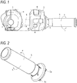
- a reference numeral M in Fig. 1 denotes a switch knob formed in the switch case S.
- a desired electric component mounted on the motorcycle may be operated by operating the desired switch knob M.
- a reference numeral 9 denotes a lid member configured to close an opening side of the case 1.
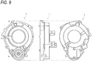
- the throttle grip G extends from the switch case S and is capable of rotating while being gripped by a driver. As shown in Figs. 1 and 2 , the throttle grip G is capable of normal rotation a about a shaft thereof in a predetermined direction from an initial position and reversed rotation b in a direction opposite to the predetermined direction. Engaging portions Ga (see Figs. 2 and 10 ), which are formed of a pair of protruding portions, are formed on the base end side of the throttle grip G. The throttle grip G and the interlocking member 2 are coupled to each other by engaging the engaging portions Ga with engaged portions 2a (see Fig. 2 and the like) of the interlocking member 2.
- the interlocking member 2 includes the engaged portions 2a which can be engaged with the engaging portions Ga formed on the throttle grip G, and can rotate in conjunction with the normal rotation a and the reversed rotation b of the throttle grip G.
- the interlocking member 2 according to the present embodiment is formed of an annular member which includes: a pair of the engaged portions 2a; a pair of accommodating portions 2b; a flange 2c; and a gear 2d.
- the engaged portions 2a are formed in concave shapes at positions corresponding to the engaging portions Ga of the throttle grip G, and the base end side of the throttle grip G is connected to the interlocking member 2 in a state where the engaging portions Ga are fitted into and engaged with the engaged portions 2a.
- the interlocking member 2 can also rotate in accordance with rotation of the throttle grip G.
- the engaged portions 2a are formed on a surface of the interlocking member 2 (surface on one side that can face outside when the interlocking member 2 is assembled to the case 1), and the accommodating portions 2b are formed on a surface on the other side.
- a pair of protruding portions 2e which are formed in arc shapes, are formed on the surface on the other side of the interlocking member 2.
- Each accommodating portion 2b is formed of a groove shape formed in an arc shape at a position between the pair of engaged portions 2a, and a compression coil spring constituting the second urging unit 5 can be accommodated therein.
- the flange 2c protrudes in a radial direction over an entire peripheral direction of the interlocking member 2.
- the gear 2d is formed over a predetermined range.
- the gear 2d is capable of meshing with a gear formed on an outer periphery of the rotating member 6.
- the rotating member 6 rotates in accordance with rotation of the interlocking member 2.
- the rotating member 6, which can rotate in conjunction with the interlocking member 2 as described above, is accommodated in an accommodating recessed portion 1c (see Fig. 9 ) formed at a predetermined position of the case 1, and is rotatable about a shaft L (see Figs. 6 and 8 ). Therefore, when the interlocking member 2 is rotated, the rotating member 6 is rotated by a rotation angle corresponding to a rotation angle of the interlocking member 2.
- a magnet m is attached to the rotating member 6, and a magnetic force generated from the magnet m changes in accordance with rotation of the rotating member 6.
- the magnetic sensor 7 (rotation angle detecting unit) is formed of a sensor that is arranged at a position on an extension line of the shaft L of the rotating member 6.
- the magnetic sensor 7 is capable of detecting a rotation angle of the throttle grip G by detecting a change in magnetism generated from the magnet m attached to the rotating member 6.
- the magnetic sensor 7 can obtain an output voltage corresponding to a magnetic field change (change in magnetic flux density) of the magnet m.
- the magnetic sensor 7 is configured by a Hall element (specifically, a linear Hall IC that can obtain an output voltage proportional to a magnetic field (magnetic flux density) of the magnet m), which is a magnetic sensor utilizing the Hall effect.
- the magnetic sensor 7 according to the present embodiment is formed on a printed circuit board 6 on which a predetermined electric circuit is printed.
- the rotating member 6 when the interlocking member 2 rotates in the same direction in accordance with the normal rotation a of the throttle grip G, the rotating member 6 also rotates in conjunction, and the magnet m attached to the rotating member 6 also rotates by the same angle in the same direction. Since the magnetic field changes in accordance with a rotation angle thereof, an output voltage corresponding to the rotation angle can be obtained, so that a rotation angle of the interlocking member 2 (that is, a rotation angle of the throttle grip G) can be detected based on the output voltage. In this way, the detected rotation angle of the throttle grip G is transmitted, as an electric signal, to an engine control unit (ECU) mounted on the motorcycle, so that an engine of the vehicle can be controlled in accordance with the transmitted rotation angle of the throttle grip G.
- ECU engine control unit
- the rotating member 6 when the interlocking member rotates in the same direction in accordance with the reversed rotation b of the throttle grip G, the rotating member 6 also rotates in conjunction, and the magnet m attached to the rotating member 6 also rotates by the same angle in the same direction.
- the magnetic field changes in accordance with a rotation angle thereof, an output voltage corresponding to the rotation angle can be obtained, so that the reversed rotation b of the throttle grip G can be detected.
- the present invention is applied to a motorcycle equipped with a constant vehicle speed holding device (auto cruise device) configured to keep a traveling speed constant.
- a constant vehicle speed holding device autonomous cruise device
- constant vehicle speed holding control can be stopped (canceled).
- the interlocking member 2 constitutes a transmission unit in which the gear 2d for transmitting a rotational force of the throttle grip G to the rotating member 6 is formed, and the second urging unit 5 is accommodated therein (in the accommodating portion 2b in the present embodiment), so that the interlocking member 2 has a function of transmitting the rotational force of the throttle grip G and a function of accommodating the second urging unit 5.
- the flange 2c whose gear 2d is formed over the predetermined range is provided.
- a stopper 1a and an abutting portion 3c of the urging force applying unit 3 which abuts against the stopper 1a are formed at positions corresponding to the protruding portions 2e.
- the stopper 1a and the abutting portion 3c can be accommodated within a diameter of the flange 2c of the interlocking member 2, which contributes to reduction in size.
- the first urging unit 4 is formed of a torsion coil spring, and is configured to urge the interlocking member 2 toward an initial position when the throttle grip G is subjected to the normal rotation a. That is, when the throttle grip G is subjected to the normal rotation a, the interlocking member 2 rotates against an urging force of the first urging unit 4, so that the urging force is transmitted to the throttle grip G, and a force which returns the throttle grip G to the initial position is applied.
- the second urging unit 5 is formed of a pair of coil springs, and is configured to urge the interlocking member 2 toward the initial position when the throttle grip G is subjected to the reversed rotation b. That is, when the throttle grip G is subjected to the reversed rotation b, the interlocking member 2 rotates against an urging force of the second urging unit 5, so that the urging force is transmitted to the throttle grip G, and a force which returns the throttle grip G to the initial position is applied.
- the urging force applying unit 3 is attached to the second urging unit 5, and is capable of not applying the urging force of the second urging unit 5 to the interlocking member 2 when the throttle grip G is subjected to the normal rotation a (at this time, only the urging force of the first urging unit 4 is applied to the interlocking member) and applying the urging force of the second urging unit 5 to the interlocking member 2 when the throttle grip G is subjected to the reversed rotation b.
- the urging force applying unit 3 is formed of an annular member which includes: a pair of protruding portions 3a; a pair of spring receivers 3b configured to receive the side of one end 5a of the second urging unit 5; and the abutting portion 3c.
- the abutting portion 3c which protrudes further in an outer diameter direction is formed on one of the pair of protruding portions 3a.
- the abutting portion 3c is located in a gap (between an end portion 2ea of one protruding portion 2e and an end portion 2eb of the other protruding portion 2e) where the pair of protruding portions 2e are formed.
- the spring receiver 3b is located in the accommodating portion 2b of the interlocking member 2 in a state where the urging force applying unit 3 is attached to the interlocking member 2, and can receive the side of one end 5a of the second urging unit 5 which is accommodated in the accommodating portion 2b as shown in Fig. 7 .
- the one end 5a of the second urging unit 5 is supported by the spring receiver 3b while the side of the other end 5b is abutted against and assembled to a wall surface 10c of the pressing unit 10.
- the abutting portion 3c is formed of a portion that is integrally formed to protrude toward a radial direction of the urging force applying unit 3.
- the abutting portion 3c can abut against the stopper 1a formed in the case 1.
- the urging force applying unit 3 is maintained in a stopping state.
- One end 4a of the first urging member 4 is locked by an end portion 2ec (see Fig. 10 ) of the protruding portion 2e formed on the interlocking member 2 while the other end 4b is locked by a locking groove 1b (see Fig. 8 ) formed in the case 1.
- the interlocking member 2 is subjected to the normal rotation a and rotates together with the urging force applying unit 3, as shown in Figs. 14A to 14C , the one end 4a is pressed against the end portion 2ec of the protruding portion 2e, and an urging force can be applied to the interlocking member 2 and the urging force applying unit 3.
- the one end 4a of the first urging unit 4 is held in a state of being located between the protruding portions 2e (between an end portion 2ed of the one protruding portion 2e and the end portion 2ec of the other protruding portion 2e) without being pressed, and the urging force of the first urging unit 4 is not applied.
- the urging force applying unit 3 is attached with the second urging unit 5.
- the urging force applying unit 3 rotates together with the interlocking member 2, and the urging force of the second urging unit 5 is not applied to the interlocking member 2 (the urging force of the first urging unit 4 is applied).
- the urging force applying unit 3 is stopped due to the abutting between the stopper 1a formed in the case 1 and the abutting portion 3c while the rotation of the interlocking member 2 is allowed, and the urging force of the second urging unit 5 can be applied to the interlocking member 2 (the urging force of the first urging unit 4 is not applied).
- the urging force of the first urging unit 4 or the second urging unit 5 can be appropriately and reliably applied to the interlocking member 2 in accordance with the rotation direction of the throttle grip G.
- the pressing unit 10 which can press the engaging portion Ga of the throttle grip G against the engaged portion 2a of the interlocking member 2 by the urging force of the second urging unit 5 when the throttle grip G is in the initial position.
- the pressing unit 10 is formed of a shaft-shaped component in which a receiving portion 10a and the wall surface 10c, which receive the urging force of the second urging unit 5, and a contact portion 10b, which comes into contact with the engaging portion Ga of the throttle grip G to apply the urging force of the second urging unit 5 to the engaging portion Ga, are integrally formed.
- the second urging unit 5 is formed of the coil spring extending in an arc shape at a position between the engaged portions 2a of the interlocking member 2, and the pressing unit 10 is attached to the end portion of the coil spring. As shown in Fig. 7 , the receiving portion 10a is abutted against and assembled to the end portion (the other end portion) of the second urging unit 5, and the urging force of the second urging unit 5 is applied to the pressing unit 10.
- a tip end of the contact portion 10b, which can come into contact with the engaging portion Ga, is formed of a spherical surface.
- the contact portion 10b is assembled in a state of being inserted into an opening 2g formed in the interlocking member 2.
- the opening 2g is formed of a hole communicating between a portion to which the second urging unit 5 is assembled and the engaged portion 2a, and is configured such that the urging force of the second urging unit 5 received by the receiving portion 10a and the wall surface 10c can be applied to the engaging portion Ga engaged with the engaged portion 2a via the contact portion 10b.
- the pressing unit 10 may also press the engaging portion Ga against a surface different from a wall surface 2ab.
- the engaged portion 2a has a recessed shaped which includes: a wall surface 2aa where the opening 2g is formed; and the wall surface 2ab which faces the wall surface 2aa.
- the engaging portion Ga which receives the urging force of the second urging unit 5 via the pressing unit 10, is pressed against the wall surface 2ab, so that rattling is not generated between the throttle grip G, which is in the initial position, and the interlocking member 2.
- the pressing unit 10 since the engaging portion Ga is pressed against the wall surface 2ab, the interlocking member 2 is pressed toward the rotation direction (the side of the normal rotation a) to prevent rattling.
- the engaging portion Ga can be positioned with respect to the engaged portion 2a.
- the engaging portion Ga presses the wall surface 2ab of the engaged portion 2a to rotate the interlocking member 2 in the same direction (the direction of the normal rotation a), and the contact between the contact portion 10b and the engaging portion Ga is maintained.
- the engaging portion Ga moves the pressing unit 10 against the urging force of the second urging unit 5 to press the wall surface 2aa of the engaged portion 2a, thereby rotating the interlocking member 2 in the same direction (the direction of the reversed rotation b).
- the contact portion 10a is submerged in the opening 2g while the contact between the contact portion 10a and the engaging portion Ga is maintained.
- the second urging unit 5, which includes the pressing unit 10 is attached to the urging force applying unit 3.
- the urging force applying unit 3 is assembled to the interlocking member 2.
- the second urging unit 5 and the pressing unit 10 may be provided between the engaged portions 2a as long as a plurality of the engaging portions and engaged portions are formed at equal intervals in the rotation direction of the throttle grip G.
- the urging force applying unit 3 which is capable of not applying the urging force of the second urging unit 5 to the interlocking member 2 when the throttle grip G is subjected to the normal rotation and applying the urging force of the second urging unit 5 to the interlocking member 2 when the throttle grip G is subjected to the reversed rotation, is provided, so that the first urging unit 4 and the second urging unit 5 can be selectively operated in accordance with the rotation direction of the throttle grip G. Therefore, the throttle grip G can be rotated more smoothly, and operability thereof can be further improved.
- the second urging unit 5 can serve both as an urging unit for generating an urging force when the throttle grip G is subjected to the reversed rotation and an urging unit for generating an urging force to prevent rattling, and rattling between the throttle grip G and the interlocking member 2 can be reduced without increasing the number of the urging units.
- the pressing unit 10 since the pressing unit 10 according to the present embodiment includes the receiving portion 10a configured to receive the urging force of the second urging unit 5 and the contact portion 10b configured to come into contact with the engaging portion Ga of the throttle grip G to apply the urging force of the second urging unit 5 to the engaging portion Ga, the urging force for preventing the rattling can be reliably applied from the pressing unit 10 to the throttle grip G.
- the second urging unit 5 since the second urging unit 5 according to the present embodiment includes the coil spring extending in the arc shape at the position between the engaged portions 2a of the interlocking member 2, and since the pressing unit 10 is attached to the end portion of the coil spring, the urging force for preventing the rattling is generated in the rotation direction of the throttle grip G, so that the normal rotation and the reversed rotation of the throttle grip G can be stably performed.
- the urging force applying unit 3 which is capable of not applying the urging force of the second urging unit 5 to the interlocking member 2 when the throttle grip G is subjected to the normal rotation and applying the urging force of the second urging unit 5 to the interlocking member 2 when the throttle grip G is subjected to the reversed rotation, is provided, and since the second urging unit 5, which includes the pressing unit 10, is attached to the urging force applying unit 3, the urging force of the second urging unit 5 can be effectively applied to the throttle grip G.
- the present invention is not limited thereto, and for example, the first urging unit 4 may be an urging unit other than the torsion coil spring (another urging unit for urging the interlocking member 2 toward the initial position when the throttle grip G is subjected to the normal rotation), and the second urging unit 5 may be an urging unit other than the coil spring (another urging unit for urging the interlocking member 2 toward the initial position when the throttle grip G is subjected to the reversed rotation).
- the magnetic sensor 7 instead of the magnetic sensor 7, other sensors (such as a sensor not using magnetism) that can detect the rotation angle of the throttle grip G may also be used.
- the present invention is sufficient as long as a predetermined function of the vehicle is activated or deactivated when rotation of the throttle grip G in a reverse direction is detected.
- the rotation of the throttle grip G in the reverse direction may start authentication of an immobilizer system or a smart entry system, activate a starter for starting an engine, activate a lighting unit during emergency such as hazard, and perform backward movement of a vehicle or the like.
- the vehicle to which the present invention is applied is not limited to a motorcycle as in the present embodiment, and the present invention may also be applied to other vehicles (for example, an ATV or a snowmobile) including the handlebar H thereon.
- the present invention can be applied with different external shapes or with addition of other functions or the like as long as the invention is a throttle grip device includes the pressing unit which is capable of pressing the engaging portion against the engaged portion by the urging force of the second urging unit when the throttle grip is in the initial position.
- a throttle grip device comprising: a throttle grip which is rotatable by a driver, and which is capable of normal rotation in a predetermined direction from an initial position and reversed rotation in a direction opposite to the predetermined direction; an interlocking member which includes an engaged portion capable of being engaged with an engaging portion formed on the throttle grip, and which is capable of rotating in conjunction with the normal rotation and the reversed rotation of the throttle grip; a case which is configured to rotatably hold the interlocking member; a first urging unit which is configured to urge the interlocking member toward the initial position when the throttle grip is subjected to the normal rotation; a second urging unit which is configured to urge the interlocking member toward the initial position when the throttle grip is subjected to the reversed rotation; and a rotation angle detecting unit which is capable of detecting a rotation angle of the throttle grip by detecting a rotation angle of the interlocking member, wherein the throttle grip device is capable of controlling an engine of a vehicle in accordance with the rotation
- the second urging unit can serve both as an urging unit for generating an urging force when the throttle grip is subjected to the reversed rotation and an urging unit for generating an urging force to prevent rattling, and rattling between the throttle grip and the interlocking member can be reduced without increasing the number of the urging units.
- the pressing unit may include: a receiving portion configured to receive the urging force of the second urging unit; and a contact portion configured to come into contact with the engaging portion of the throttle grip to apply the urging force of the second urging unit to the engaging portion.
- the pressing unit since the pressing unit includes the receiving portion configured to receive the urging force of the second urging unit and the contact portion configured to come into contact with the engaging portion of the throttle grip to apply the urging force of the second urging unit to the engaging portion, the urging force for preventing the rattling can be reliably applied from the pressing unit to the throttle grip.
- the engaged portion of the interlocking member may include a pair of engaged portions
- the second urging unit may include a coil spring extending in an arc shape at a position between the engaged portions, and the pressing unit may be attached to an end portion of the coil spring.
- the second urging unit since the second urging unit includes the coil spring extending in the arc shape at the position between the engaged portions of the interlocking member, and since the pressing unit is attached to the end portion of the coil spring, the urging force for preventing the rattling is generated in a rotation direction of the throttle grip, so that the normal rotation and the reversed rotation of the throttle grip can be stably performed.
- the throttle grip device may further comprise: an urging force applying unit which is capable of not applying the urging force of the second urging unit to the interlocking member when the throttle grip is subjected to the normal rotation and applying the urging force of the second urging unit to the interlocking member when the throttle grip is subjected to the reversed rotation, and the second urging unit, which includes the pressing unit, is attached to the urging force applying unit.
- the urging force applying unit which is capable of not applying the urging force of the second urging unit to the interlocking member when the throttle grip is subjected to the normal rotation and applying the urging force of the second urging unit to the interlocking member when the throttle grip is subjected to the reversed rotation, is provided, and since the second urging unit, which includes the pressing unit, is attached to the urging force applying unit, the urging force of the second urging unit can be effectively applied to the throttle grip.
Landscapes
- Engineering & Computer Science (AREA)
- Mechanical Engineering (AREA)
- Chemical & Material Sciences (AREA)
- Combustion & Propulsion (AREA)
- General Engineering & Computer Science (AREA)
- Control Of Throttle Valves Provided In The Intake System Or In The Exhaust System (AREA)
- Steering Devices For Bicycles And Motorcycles (AREA)
Abstract
Description
- The present invention relates to a throttle grip device configured to control an engine of a vehicle based on rotation of a throttle grip.
- In a recent motorcycle, it is widespread that a rotation angle of a throttle grip is detected by a throttle opening sensor such as a potentiometer, and a detected value thereof is transmitted, as an electric signal, to an electronic control device or the like that is mounted on the motorcycle. The electronic control device performs a predetermined calculation based on the detected signal such that ignition timing of the engine and opening and closing of an intake valve or a throttle valve are controlled based on a result of the calculation.
- For example,
JP-A-2018-91202 - In such a throttle grip device in related art, an engaging portion formed on the throttle grip is engaged with an engaged portion formed on an interlocking member, and the interlocking member is rotated in the same direction as that of the throttle grip in conjunction with the normal rotation and the reversed rotation of the throttle grip. Moreover, such a throttle grip device in the related art includes: a first urging unit configured to urge the interlocking member toward an initial position when the throttle grip is subjected to the normal rotation; and a second urging unit configured to urge the interlocking member toward the initial position when the throttle grip is subjected to the reversed rotation.
- However, in the throttle grip device in the related art, since the engaging portion of the throttle grip is engaged with the engaged portion of the interlocking member and the interlocking member is interlocked, rattling is likely to occur between the throttle grip and the interlocking member. Moreover, although it is also conceivable to prevent the rattling through using another urging unit separate from the first urging unit and the second urging unit, the number of components is increased in this case, and a manufacturing cost is increased.
- The present invention has been made in view of the above circumstances, and provides a throttle grip device which is capable of reducing the rattling between the throttle grip and the interlocking member without increasing the number of the urging units.
- According to an aspect of the invention, there is provided a throttle grip device comprising: a throttle grip which is rotatable by a driver, and which is capable of normal rotation in a predetermined direction from an initial position and reversed rotation in a direction opposite to the predetermined direction; an interlocking member which includes an engaged portion capable of being engaged with an engaging portion formed on the throttle grip, and which is capable of rotating in conjunction with the normal rotation and the reversed rotation of the throttle grip; a case which is configured to rotatably hold the interlocking member; a first urging unit which is configured to urge the interlocking member toward the initial position when the throttle grip is subjected to the normal rotation; a second urging unit which is configured to urge the interlocking member toward the initial position when the throttle grip is subjected to the reversed rotation; and a rotation angle detecting unit which is capable of detecting a rotation angle of the throttle grip by detecting a rotation angle of the interlocking member, wherein the throttle grip device is capable of controlling an engine of a vehicle in accordance with the rotation angle of the throttle grip detected by the rotation angle detecting unit when the throttle grip is subjected to the normal rotation, and is capable of activating or deactivating a predetermined function of the vehicle when the throttle grip is subjected to the reversed rotation, and wherein the throttle grip device further comprises: a pressing unit which is capable of pressing the engaging portion against the engaged portion by an urging force of the second urging unit when the throttle grip is in the initial position.
-
-
Fig. 1 includes a side view and a front view showing a throttle grip and a switch case of a vehicle to which a throttle grip device according to an embodiment of the present invention is applied. -
Fig. 2 is a perspective view showing a throttle grip of the throttle grip device. -
Fig. 3 is a perspective view showing the throttle grip device. -
Fig. 4 is a three-sided view showing the throttle grip device. -
Fig. 5 is a cross-sectional view taken along line V-V ofFig. 4 . -
Fig. 6 is a cross-sectional view taken along line VI-VI ofFig. 4 . -
Fig. 7 is a cross-sectional view taken along line VII-VII ofFig. 6 . -
Fig. 8 is a cross-sectional view taken along line VIII-VIII ofFig. 6 . -
Fig. 9 is a three-sided view showing a case of the throttle grip device. -
Fig. 10 is a four-sided view showing an interlocking member of the throttle grip device. -
Fig. 11 is a four-sided view showing an urging force applying unit of the throttle grip device. -
Fig. 12 is a three-sided view showing a pressing unit of the throttle grip device. -
Figs. 13A to 13C are explanatory diagrams showing an operation of the urging force applying unit of the throttle grip device, and are schematic views showing a state where the urging force applying unit and the interlocking member are in an initial position. -
Figs. 14A to 14C are explanatory diagrams showing the operation of the urging force applying unit of the throttle grip device, and are schematic views showing a state of the urging force applying unit and the interlocking member when the throttle grip is subjected to normal rotation. -
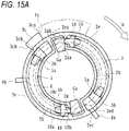
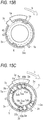
Figs. 15A to 15C are explanatory diagrams showing the operation of the urging force applying unit of the throttle grip device, and are schematic views showing a state of the urging force applying unit and the interlocking member when the throttle grip is subjected to reversed rotation. - Hereinafter, an embodiment of the present invention will be described in detail with reference to the drawings.
- As shown in
Fig. 1 , a throttle grip device according to the present embodiment is configured to detect a rotation angle of a throttle grip G attached to a handlebar H of a motorcycle, and to transmit a detected signal thereof to an electronic control device, such as an ECU, mounted on the motorcycle. As shown inFigs. 2 to 8 , the throttle grip device includes: the throttle grip G; acase 1; an interlockingmember 2; an urgingforce applying unit 3; afirst urging unit 4; asecond urging unit 5; a rotatingmember 6; a magnetic sensor 7 (rotation angle detecting unit); and apressing unit 10. - The
case 1 is arranged in a switch case S (seeFig. 1 ) attached to a front end side (a base end side of the throttle grip G) of the handlebar H of the motorcycle (vehicle). Thecase 1 accommodates various components constituting the throttle grip device, and holds the interlockingmember 2, the urgingforce applying unit 3, the rotatingmember 6 and the like in a rotatable manner. A reference numeral M inFig. 1 denotes a switch knob formed in the switch case S. A desired electric component mounted on the motorcycle may be operated by operating the desired switch knob M.A reference numeral 9 denotes a lid member configured to close an opening side of thecase 1. - The throttle grip G extends from the switch case S and is capable of rotating while being gripped by a driver. As shown in
Figs. 1 and 2 , the throttle grip G is capable of normal rotation a about a shaft thereof in a predetermined direction from an initial position and reversed rotation b in a direction opposite to the predetermined direction. Engaging portions Ga (seeFigs. 2 and10 ), which are formed of a pair of protruding portions, are formed on the base end side of the throttle grip G. The throttle grip G and the interlockingmember 2 are coupled to each other by engaging the engaging portions Ga with engagedportions 2a (seeFig. 2 and the like) of the interlockingmember 2. - The interlocking
member 2 includes the engagedportions 2a which can be engaged with the engaging portions Ga formed on the throttle grip G, and can rotate in conjunction with the normal rotation a and the reversed rotation b of the throttle grip G. Specifically, as shown inFig. 10 , the interlockingmember 2 according to the present embodiment is formed of an annular member which includes: a pair of the engagedportions 2a; a pair ofaccommodating portions 2b; aflange 2c; and agear 2d. - The engaged
portions 2a are formed in concave shapes at positions corresponding to the engaging portions Ga of the throttle grip G, and the base end side of the throttle grip G is connected to the interlockingmember 2 in a state where the engaging portions Ga are fitted into and engaged with the engagedportions 2a. As a result, the interlockingmember 2 can also rotate in accordance with rotation of the throttle grip G. The engagedportions 2a are formed on a surface of the interlocking member 2 (surface on one side that can face outside when the interlockingmember 2 is assembled to the case 1), and theaccommodating portions 2b are formed on a surface on the other side. A pair ofprotruding portions 2e, which are formed in arc shapes, are formed on the surface on the other side of the interlockingmember 2. - Each
accommodating portion 2b is formed of a groove shape formed in an arc shape at a position between the pair of engagedportions 2a, and a compression coil spring constituting thesecond urging unit 5 can be accommodated therein. Theflange 2c protrudes in a radial direction over an entire peripheral direction of the interlockingmember 2. Thegear 2d is formed over a predetermined range. Thegear 2d is capable of meshing with a gear formed on an outer periphery of the rotatingmember 6. The rotatingmember 6 rotates in accordance with rotation of the interlockingmember 2. - The rotating
member 6, which can rotate in conjunction with the interlockingmember 2 as described above, is accommodated in an accommodating recessed portion 1c (seeFig. 9 ) formed at a predetermined position of thecase 1, and is rotatable about a shaft L (seeFigs. 6 and8 ). Therefore, when the interlockingmember 2 is rotated, the rotatingmember 6 is rotated by a rotation angle corresponding to a rotation angle of the interlockingmember 2. A magnet m is attached to the rotatingmember 6, and a magnetic force generated from the magnet m changes in accordance with rotation of the rotatingmember 6. - As shown in
Fig. 6 , the magnetic sensor 7 (rotation angle detecting unit) is formed of a sensor that is arranged at a position on an extension line of the shaft L of the rotatingmember 6. Themagnetic sensor 7 is capable of detecting a rotation angle of the throttle grip G by detecting a change in magnetism generated from the magnet m attached to the rotatingmember 6. Specifically, themagnetic sensor 7 can obtain an output voltage corresponding to a magnetic field change (change in magnetic flux density) of the magnet m. For example, themagnetic sensor 7 is configured by a Hall element (specifically, a linear Hall IC that can obtain an output voltage proportional to a magnetic field (magnetic flux density) of the magnet m), which is a magnetic sensor utilizing the Hall effect. Themagnetic sensor 7 according to the present embodiment is formed on a printedcircuit board 6 on which a predetermined electric circuit is printed. - Therefore, when the interlocking
member 2 rotates in the same direction in accordance with the normal rotation a of the throttle grip G, the rotatingmember 6 also rotates in conjunction, and the magnet m attached to the rotatingmember 6 also rotates by the same angle in the same direction. Since the magnetic field changes in accordance with a rotation angle thereof, an output voltage corresponding to the rotation angle can be obtained, so that a rotation angle of the interlocking member 2 (that is, a rotation angle of the throttle grip G) can be detected based on the output voltage. In this way, the detected rotation angle of the throttle grip G is transmitted, as an electric signal, to an engine control unit (ECU) mounted on the motorcycle, so that an engine of the vehicle can be controlled in accordance with the transmitted rotation angle of the throttle grip G. - On the other hand, when the interlocking member rotates in the same direction in accordance with the reversed rotation b of the throttle grip G, the rotating
member 6 also rotates in conjunction, and the magnet m attached to the rotatingmember 6 also rotates by the same angle in the same direction. As a result, since the magnetic field changes in accordance with a rotation angle thereof, an output voltage corresponding to the rotation angle can be obtained, so that the reversed rotation b of the throttle grip G can be detected. - In this way, when the reversed rotation b of the throttle grip G is detected, a predetermined function of the motorcycle can be activated or deactivated. In the present embodiment, the present invention is applied to a motorcycle equipped with a constant vehicle speed holding device (auto cruise device) configured to keep a traveling speed constant. When the throttle grip G is subjected to the reversed rotation b (rotation in a direction opposite to a direction of the normal rotation a for fully opening a throttle from an initial position), constant vehicle speed holding control can be stopped (canceled).
- Therefore, the interlocking
member 2 according to the present embodiment constitutes a transmission unit in which thegear 2d for transmitting a rotational force of the throttle grip G to the rotatingmember 6 is formed, and thesecond urging unit 5 is accommodated therein (in theaccommodating portion 2b in the present embodiment), so that the interlockingmember 2 has a function of transmitting the rotational force of the throttle grip G and a function of accommodating thesecond urging unit 5. - In the interlocking
member 2 according to the present embodiment, theflange 2c whosegear 2d is formed over the predetermined range is provided. As shown inFigs. 9 to 11 , a stopper 1a and an abuttingportion 3c of the urgingforce applying unit 3 which abuts against the stopper 1a are formed at positions corresponding to the protrudingportions 2e. As a result, the stopper 1a and the abuttingportion 3c can be accommodated within a diameter of theflange 2c of the interlockingmember 2, which contributes to reduction in size. - The
first urging unit 4 is formed of a torsion coil spring, and is configured to urge the interlockingmember 2 toward an initial position when the throttle grip G is subjected to the normal rotation a. That is, when the throttle grip G is subjected to the normal rotation a, the interlockingmember 2 rotates against an urging force of thefirst urging unit 4, so that the urging force is transmitted to the throttle grip G, and a force which returns the throttle grip G to the initial position is applied. - The
second urging unit 5 is formed of a pair of coil springs, and is configured to urge the interlockingmember 2 toward the initial position when the throttle grip G is subjected to the reversed rotation b. That is, when the throttle grip G is subjected to the reversed rotation b, the interlockingmember 2 rotates against an urging force of thesecond urging unit 5, so that the urging force is transmitted to the throttle grip G, and a force which returns the throttle grip G to the initial position is applied. - The urging
force applying unit 3 is attached to thesecond urging unit 5, and is capable of not applying the urging force of thesecond urging unit 5 to the interlockingmember 2 when the throttle grip G is subjected to the normal rotation a (at this time, only the urging force of thefirst urging unit 4 is applied to the interlocking member) and applying the urging force of thesecond urging unit 5 to the interlockingmember 2 when the throttle grip G is subjected to the reversed rotation b. Specifically, as shown inFig. 11 , the urgingforce applying unit 3 is formed of an annular member which includes: a pair of protrudingportions 3a; a pair ofspring receivers 3b configured to receive the side of oneend 5a of thesecond urging unit 5; and the abuttingportion 3c. - The abutting
portion 3c which protrudes further in an outer diameter direction is formed on one of the pair of protrudingportions 3a. In a state where the urgingforce applying unit 3 is assembled to the interlockingmember 2, as shown inFigs. 13A to 13C , the abuttingportion 3c is located in a gap (between an end portion 2ea of one protrudingportion 2e and an end portion 2eb of the other protrudingportion 2e) where the pair of protrudingportions 2e are formed. When the interlockingmember 2 is subjected to the normal rotation a, as shown inFigs. 14A to 14C , the end 2ea of the protrudingportion 2e presses one end surface 3ca of the abuttingportion 3c, and the urgingforce applying unit 3 is rotated together with the interlockingmember 2. On the other hand, when the interlockingmember 2 is subjected to the reversed rotation b, as shown inFigs. 15A to 15C , the end portion 2eb of the other protrudingportion 2e is rotated until the end portion 2eb is abutted against the other end surface 3cb of the abuttingportion 3c, and the other end surface 3ca is not pressed until such abutting occurs, so that the urgingforce applying unit 3 is stopped while rotation of the interlockingmember 2 is allowed. - The
spring receiver 3b is located in theaccommodating portion 2b of the interlockingmember 2 in a state where the urgingforce applying unit 3 is attached to the interlockingmember 2, and can receive the side of oneend 5a of thesecond urging unit 5 which is accommodated in theaccommodating portion 2b as shown inFig. 7 . The oneend 5a of thesecond urging unit 5 is supported by thespring receiver 3b while the side of theother end 5b is abutted against and assembled to awall surface 10c of thepressing unit 10. When the interlockingmember 2 and the urgingforce applying unit 3 rotate together (seeFigs. 14A to 14C ), an urging force of thesecond urging unit 5 is not applied. When the urgingforce applying unit 3 is stopped while the interlockingmember 2 rotates (seeFigs. 15A to 15C ), thesecond urging unit 5 is compressed and the urging force is applied to the interlockingmember 2. - Further, the abutting
portion 3c is formed of a portion that is integrally formed to protrude toward a radial direction of the urgingforce applying unit 3. When the interlockingmember 2 is subjected to the reversed rotation b, as shown inFigs. 15A to 15C , the abuttingportion 3c can abut against the stopper 1a formed in thecase 1. As a result, even if the interlockingmember 2 is subjected to the reversed rotation b and receives a reaction force due to the urging force of thesecond urging unit 5, the urgingforce applying unit 3 is maintained in a stopping state. - One
end 4a of the first urgingmember 4 is locked by an end portion 2ec (seeFig. 10 ) of the protrudingportion 2e formed on the interlockingmember 2 while theother end 4b is locked by a lockinggroove 1b (seeFig. 8 ) formed in thecase 1. When the interlockingmember 2 is subjected to the normal rotation a and rotates together with the urgingforce applying unit 3, as shown inFigs. 14A to 14C , the oneend 4a is pressed against the end portion 2ec of the protrudingportion 2e, and an urging force can be applied to the interlockingmember 2 and the urgingforce applying unit 3. On the other hand, when the interlockingmember 2 is subjected to the reversed rotation b, as shown inFigs. 15A to 15C , the oneend 4a of thefirst urging unit 4 is held in a state of being located between the protrudingportions 2e (between an end portion 2ed of the one protrudingportion 2e and the end portion 2ec of the other protrudingportion 2e) without being pressed, and the urging force of thefirst urging unit 4 is not applied. - As described above, the urging
force applying unit 3 according to the present embodiment is attached with thesecond urging unit 5. When the throttle grip G is subjected to the normal rotation a, the urgingforce applying unit 3 rotates together with the interlockingmember 2, and the urging force of thesecond urging unit 5 is not applied to the interlocking member 2 (the urging force of thefirst urging unit 4 is applied). When the throttle grip G is subjected to the reversed rotation b, the urgingforce applying unit 3 is stopped due to the abutting between the stopper 1a formed in thecase 1 and the abuttingportion 3c while the rotation of the interlockingmember 2 is allowed, and the urging force of thesecond urging unit 5 can be applied to the interlocking member 2 (the urging force of thefirst urging unit 4 is not applied). As a result, the urging force of thefirst urging unit 4 or thesecond urging unit 5 can be appropriately and reliably applied to the interlockingmember 2 in accordance with the rotation direction of the throttle grip G. - Here, in the present embodiment, the
pressing unit 10, which can press the engaging portion Ga of the throttle grip G against the engagedportion 2a of the interlockingmember 2 by the urging force of thesecond urging unit 5 when the throttle grip G is in the initial position, is provided. As shown inFig. 12 , thepressing unit 10 is formed of a shaft-shaped component in which a receivingportion 10a and thewall surface 10c, which receive the urging force of thesecond urging unit 5, and acontact portion 10b, which comes into contact with the engaging portion Ga of the throttle grip G to apply the urging force of thesecond urging unit 5 to the engaging portion Ga, are integrally formed. - However, as described above, the
second urging unit 5 is formed of the coil spring extending in an arc shape at a position between theengaged portions 2a of the interlockingmember 2, and thepressing unit 10 is attached to the end portion of the coil spring. As shown inFig. 7 , the receivingportion 10a is abutted against and assembled to the end portion (the other end portion) of thesecond urging unit 5, and the urging force of thesecond urging unit 5 is applied to thepressing unit 10. - A tip end of the
contact portion 10b, which can come into contact with the engaging portion Ga, is formed of a spherical surface. Thecontact portion 10b is assembled in a state of being inserted into anopening 2g formed in the interlockingmember 2. Theopening 2g is formed of a hole communicating between a portion to which thesecond urging unit 5 is assembled and the engagedportion 2a, and is configured such that the urging force of thesecond urging unit 5 received by the receivingportion 10a and thewall surface 10c can be applied to the engaging portion Ga engaged with the engagedportion 2a via thecontact portion 10b. Thepressing unit 10 may also press the engaging portion Ga against a surface different from a wall surface 2ab. - The engaged
portion 2a, as shown inFigs. 7 and13A to 13C , has a recessed shaped which includes: a wall surface 2aa where theopening 2g is formed; and the wall surface 2ab which faces the wall surface 2aa. The engaging portion Ga, which receives the urging force of thesecond urging unit 5 via thepressing unit 10, is pressed against the wall surface 2ab, so that rattling is not generated between the throttle grip G, which is in the initial position, and the interlockingmember 2. In this way, in thepressing unit 10 according to the present embodiment, since the engaging portion Ga is pressed against the wall surface 2ab, the interlockingmember 2 is pressed toward the rotation direction (the side of the normal rotation a) to prevent rattling. In addition to prevention of the rattling of the throttle grip G located in the initial position, the engaging portion Ga can be positioned with respect to the engagedportion 2a. - When the throttle grip G is subjected to the normal rotation a from the initial position, as shown in
Figs. 14A to 14C , the engaging portion Ga presses the wall surface 2ab of the engagedportion 2a to rotate the interlockingmember 2 in the same direction (the direction of the normal rotation a), and the contact between thecontact portion 10b and the engaging portion Ga is maintained. Further, when the throttle G is subjected to the reversed rotation b from the initial position, as shown inFigs. 15A to 15C , the engaging portion Ga moves thepressing unit 10 against the urging force of thesecond urging unit 5 to press the wall surface 2aa of the engagedportion 2a, thereby rotating the interlockingmember 2 in the same direction (the direction of the reversed rotation b). At this time, thecontact portion 10a is submerged in theopening 2g while the contact between thecontact portion 10a and the engaging portion Ga is maintained. - Further, in the present embodiment, the
second urging unit 5, which includes thepressing unit 10, is attached to the urgingforce applying unit 3. The urgingforce applying unit 3 is assembled to the interlockingmember 2. As a result, it is not necessary to provide a special installation space for thepressing unit 10, and a space between the urgingforce applying unit 3 and the interlockingmember 2 can be effectively used, so that a dead space can be prevented from being formed in thecase 1. - Although there are two engaging portions Ga of the throttle grip G and two engaged
portions 2a of the interlockingmember 2 formed at equal intervals in the rotation direction of the throttle grip G in the present embodiment, for example, three or more may be formed, and thesecond urging unit 5 and thepressing unit 10 may be provided between theengaged portions 2a as long as a plurality of the engaging portions and engaged portions are formed at equal intervals in the rotation direction of the throttle grip G. - Since the urging
force applying unit 3, which is capable of not applying the urging force of thesecond urging unit 5 to the interlockingmember 2 when the throttle grip G is subjected to the normal rotation and applying the urging force of thesecond urging unit 5 to the interlockingmember 2 when the throttle grip G is subjected to the reversed rotation, is provided, so that thefirst urging unit 4 and thesecond urging unit 5 can be selectively operated in accordance with the rotation direction of the throttle grip G. Therefore, the throttle grip G can be rotated more smoothly, and operability thereof can be further improved. - According to the present embodiment, since the
pressing unit 10, which can press the engaging portion Ga against the engagedportion 2a by the urging force of thesecond urging unit 5 when the throttle grip G is in the initial position, is provided, thesecond urging unit 5 can serve both as an urging unit for generating an urging force when the throttle grip G is subjected to the reversed rotation and an urging unit for generating an urging force to prevent rattling, and rattling between the throttle grip G and the interlockingmember 2 can be reduced without increasing the number of the urging units. - Since the
pressing unit 10 according to the present embodiment includes the receivingportion 10a configured to receive the urging force of thesecond urging unit 5 and thecontact portion 10b configured to come into contact with the engaging portion Ga of the throttle grip G to apply the urging force of thesecond urging unit 5 to the engaging portion Ga, the urging force for preventing the rattling can be reliably applied from thepressing unit 10 to the throttle grip G. Further, since thesecond urging unit 5 according to the present embodiment includes the coil spring extending in the arc shape at the position between theengaged portions 2a of the interlockingmember 2, and since thepressing unit 10 is attached to the end portion of the coil spring, the urging force for preventing the rattling is generated in the rotation direction of the throttle grip G, so that the normal rotation and the reversed rotation of the throttle grip G can be stably performed. - Still further, since the urging
force applying unit 3, which is capable of not applying the urging force of thesecond urging unit 5 to the interlockingmember 2 when the throttle grip G is subjected to the normal rotation and applying the urging force of thesecond urging unit 5 to the interlockingmember 2 when the throttle grip G is subjected to the reversed rotation, is provided, and since thesecond urging unit 5, which includes thepressing unit 10, is attached to the urgingforce applying unit 3, the urging force of thesecond urging unit 5 can be effectively applied to the throttle grip G. - Although the present embodiment has been described above, the present invention is not limited thereto, and for example, the
first urging unit 4 may be an urging unit other than the torsion coil spring (another urging unit for urging the interlockingmember 2 toward the initial position when the throttle grip G is subjected to the normal rotation), and thesecond urging unit 5 may be an urging unit other than the coil spring (another urging unit for urging the interlockingmember 2 toward the initial position when the throttle grip G is subjected to the reversed rotation). Moreover, instead of themagnetic sensor 7, other sensors (such as a sensor not using magnetism) that can detect the rotation angle of the throttle grip G may also be used. - Further, although the constant vehicle speed holding control of the constant vehicle speed holding device (auto cruise device) is stopped (canceled) when the throttle grip G is subjected to the reversed rotation in the present embodiment, the present invention is sufficient as long as a predetermined function of the vehicle is activated or deactivated when rotation of the throttle grip G in a reverse direction is detected. For example, the rotation of the throttle grip G in the reverse direction may start authentication of an immobilizer system or a smart entry system, activate a starter for starting an engine, activate a lighting unit during emergency such as hazard, and perform backward movement of a vehicle or the like. The vehicle to which the present invention is applied is not limited to a motorcycle as in the present embodiment, and the present invention may also be applied to other vehicles (for example, an ATV or a snowmobile) including the handlebar H thereon.
- The present invention can be applied with different external shapes or with addition of other functions or the like as long as the invention is a throttle grip device includes the pressing unit which is capable of pressing the engaging portion against the engaged portion by the urging force of the second urging unit when the throttle grip is in the initial position.
- According to an aspect of the invention, there is provided a throttle grip device comprising: a throttle grip which is rotatable by a driver, and which is capable of normal rotation in a predetermined direction from an initial position and reversed rotation in a direction opposite to the predetermined direction; an interlocking member which includes an engaged portion capable of being engaged with an engaging portion formed on the throttle grip, and which is capable of rotating in conjunction with the normal rotation and the reversed rotation of the throttle grip; a case which is configured to rotatably hold the interlocking member; a first urging unit which is configured to urge the interlocking member toward the initial position when the throttle grip is subjected to the normal rotation; a second urging unit which is configured to urge the interlocking member toward the initial position when the throttle grip is subjected to the reversed rotation; and a rotation angle detecting unit which is capable of detecting a rotation angle of the throttle grip by detecting a rotation angle of the interlocking member, wherein the throttle grip device is capable of controlling an engine of a vehicle in accordance with the rotation angle of the throttle grip detected by the rotation angle detecting unit when the throttle grip is subjected to the normal rotation, and is capable of activating or deactivating a predetermined function of the vehicle when the throttle grip is subjected to the reversed rotation, and wherein the throttle grip device further comprises: a pressing unit which is capable of pressing the engaging portion against the engaged portion by an urging force of the second urging unit when the throttle grip is in the initial position.
- According to the above aspect of the invention, since the pressing unit, which can press the engaging portion against the engaged portion by the urging force of the second urging unit when the throttle grip is in the initial position, is provided, the second urging unit can serve both as an urging unit for generating an urging force when the throttle grip is subjected to the reversed rotation and an urging unit for generating an urging force to prevent rattling, and rattling between the throttle grip and the interlocking member can be reduced without increasing the number of the urging units.
- The pressing unit may include: a receiving portion configured to receive the urging force of the second urging unit; and a contact portion configured to come into contact with the engaging portion of the throttle grip to apply the urging force of the second urging unit to the engaging portion.
- According to the above aspect of the invention, since the pressing unit includes the receiving portion configured to receive the urging force of the second urging unit and the contact portion configured to come into contact with the engaging portion of the throttle grip to apply the urging force of the second urging unit to the engaging portion, the urging force for preventing the rattling can be reliably applied from the pressing unit to the throttle grip.
- The engaged portion of the interlocking member may include a pair of engaged portions, the second urging unit may include a coil spring extending in an arc shape at a position between the engaged portions, and the pressing unit may be attached to an end portion of the coil spring.
- According to the above aspect of the invention, since the second urging unit includes the coil spring extending in the arc shape at the position between the engaged portions of the interlocking member, and since the pressing unit is attached to the end portion of the coil spring, the urging force for preventing the rattling is generated in a rotation direction of the throttle grip, so that the normal rotation and the reversed rotation of the throttle grip can be stably performed.
- The throttle grip device may further comprise: an urging force applying unit which is capable of not applying the urging force of the second urging unit to the interlocking member when the throttle grip is subjected to the normal rotation and applying the urging force of the second urging unit to the interlocking member when the throttle grip is subjected to the reversed rotation, and the second urging unit, which includes the pressing unit, is attached to the urging force applying unit.
- According to the above aspect of the present invention, since the urging force applying unit, which is capable of not applying the urging force of the second urging unit to the interlocking member when the throttle grip is subjected to the normal rotation and applying the urging force of the second urging unit to the interlocking member when the throttle grip is subjected to the reversed rotation, is provided, and since the second urging unit, which includes the pressing unit, is attached to the urging force applying unit, the urging force of the second urging unit can be effectively applied to the throttle grip.
Claims (4)
- A throttle grip device comprising:a throttle grip which is rotatable by a driver, and which is capable of normal rotation in a predetermined direction from an initial position and reversed rotation in a direction opposite to the predetermined direction;an interlocking member which includes an engaged portion capable of being engaged with an engaging portion formed on the throttle grip, and which is capable of rotating in conjunction with the normal rotation and the reversed rotation of the throttle grip;a case which is configured to rotatably hold the interlocking member;a first urging unit which is configured to urge the interlocking member toward the initial position when the throttle grip is subjected to the normal rotation;a second urging unit which is configured to urge the interlocking member toward the initial position when the throttle grip is subjected to the reversed rotation; anda rotation angle detecting unit which is capable of detecting a rotation angle of the throttle grip by detecting a rotation angle of the interlocking member,wherein the throttle grip device is capable of controlling an engine of a vehicle in accordance with the rotation angle of the throttle grip detected by the rotation angle detecting unit when the throttle grip is subjected to the normal rotation, and is capable of activating or deactivating a predetermined function of the vehicle when the throttle grip is subjected to the reversed rotation, andwherein the throttle grip device further comprises: a pressing unit which is capable of pressing the engaging portion against the engaged portion by an urging force of the second urging unit when the throttle grip is in the initial position.
- The throttle grip device according to claim 1, wherein
the pressing unit includes: a receiving portion configured to receive the urging force of the second urging unit; and a contact portion configured to come into contact with the engaging portion of the throttle grip to apply the urging force of the second urging unit to the engaging portion. - The throttle grip device according to claim 2, wherein
the engaged portion of the interlocking member includes a pair of engaged portions,
the second urging unit includes a coil spring extending in an arc shape at a position between the engaged portions, and
the pressing unit is attached to an end portion of the coil spring. - The throttle grip device according to any one of claims 1 to 3, further comprising: an urging force applying unit which is capable of not applying the urging force of the second urging unit to the interlocking member when the throttle grip is subjected to the normal rotation and applying the urging force of the second urging unit to the interlocking member when the throttle grip is subjected to the reversed rotation, wherein the second urging unit, which includes the pressing unit, is attached to the urging force applying unit.
Applications Claiming Priority (1)
| Application Number | Priority Date | Filing Date | Title |
|---|---|---|---|
| JP2019104841A JP7337340B2 (en) | 2019-06-04 | 2019-06-04 | throttle grip device |
Publications (3)
| Publication Number | Publication Date |
|---|---|
| EP3747750A1 true EP3747750A1 (en) | 2020-12-09 |
| EP3747750B1 EP3747750B1 (en) | 2024-10-02 |
| EP3747750C0 EP3747750C0 (en) | 2024-10-02 |
Family
ID=70977736
Family Applications (1)
| Application Number | Title | Priority Date | Filing Date |
|---|---|---|---|
| EP20178146.5A Active EP3747750B1 (en) | 2019-06-04 | 2020-06-04 | Bidirectional throttle grip device |
Country Status (3)
| Country | Link |
|---|---|
| US (1) | US11440612B2 (en) |
| EP (1) | EP3747750B1 (en) |
| JP (1) | JP7337340B2 (en) |
Cited By (1)
| Publication number | Priority date | Publication date | Assignee | Title |
|---|---|---|---|---|
| EP4072932B1 (en) * | 2019-12-10 | 2024-07-17 | Hirschmann Automotive GmbH | E-throttle having integrated switch block |
Families Citing this family (2)
| Publication number | Priority date | Publication date | Assignee | Title |
|---|---|---|---|---|
| JP2024058440A (en) * | 2022-10-14 | 2024-04-25 | 朝日電装株式会社 | Throttle grip device |
| WO2024134835A1 (en) * | 2022-12-22 | 2024-06-27 | ヤマハ発動機株式会社 | Straddled vehicle |
Citations (3)
| Publication number | Priority date | Publication date | Assignee | Title |
|---|---|---|---|---|
| US20090075532A1 (en) * | 2007-09-13 | 2009-03-19 | Yamaha Marine Kabushiki Kaisha | Boat propulsion unit |
| JP2018091202A (en) | 2016-12-01 | 2018-06-14 | 朝日電装株式会社 | Throttle grip device |
| JP2019082151A (en) * | 2017-10-31 | 2019-05-30 | 朝日電装株式会社 | Throttle grip device |
Family Cites Families (10)
| Publication number | Priority date | Publication date | Assignee | Title |
|---|---|---|---|---|
| JP2009108879A (en) | 2007-10-26 | 2009-05-21 | Mikuni Corp | Ball type joint and throttle device provided with the same |
| JP5358417B2 (en) * | 2009-12-08 | 2013-12-04 | 本田技研工業株式会社 | Accelerator operating device |
| JP2013204450A (en) * | 2012-03-27 | 2013-10-07 | Honda Motor Co Ltd | Throttle device |
| ES2810775T3 (en) * | 2013-07-24 | 2021-03-09 | Nanjing Vmoto Co Ltd | Forward and reverse speed adjusting handle for electric vehicle and electric vehicle power control device |
| JP6231349B2 (en) | 2013-10-23 | 2017-11-15 | 朝日電装株式会社 | Throttle grip device |
| CN206243366U (en) | 2016-11-23 | 2017-06-13 | 郑州大学 | One kind rotation carter's bicycle brake device |
| US10377441B2 (en) | 2016-12-01 | 2019-08-13 | Asahi Denso Co., Ltd. | Throttle grip apparatus |
| JP6792585B2 (en) | 2017-03-15 | 2020-11-25 | 株式会社エクセディ | Power transmission device and motorcycle |
| JP6655641B2 (en) * | 2018-03-13 | 2020-02-26 | 本田技研工業株式会社 | Throttle opening detection device for saddle type vehicle |
| US10850795B2 (en) * | 2019-01-29 | 2020-12-01 | Asahi Denso Co., Ltd. | Throttle grip device |
-
2019
- 2019-06-04 JP JP2019104841A patent/JP7337340B2/en active Active
-
2020
- 2020-06-03 US US16/891,811 patent/US11440612B2/en active Active
- 2020-06-04 EP EP20178146.5A patent/EP3747750B1/en active Active
Patent Citations (3)
| Publication number | Priority date | Publication date | Assignee | Title |
|---|---|---|---|---|
| US20090075532A1 (en) * | 2007-09-13 | 2009-03-19 | Yamaha Marine Kabushiki Kaisha | Boat propulsion unit |
| JP2018091202A (en) | 2016-12-01 | 2018-06-14 | 朝日電装株式会社 | Throttle grip device |
| JP2019082151A (en) * | 2017-10-31 | 2019-05-30 | 朝日電装株式会社 | Throttle grip device |
Cited By (1)
| Publication number | Priority date | Publication date | Assignee | Title |
|---|---|---|---|---|
| EP4072932B1 (en) * | 2019-12-10 | 2024-07-17 | Hirschmann Automotive GmbH | E-throttle having integrated switch block |
Also Published As
| Publication number | Publication date |
|---|---|
| JP7337340B2 (en) | 2023-09-04 |
| US11440612B2 (en) | 2022-09-13 |
| JP2020196387A (en) | 2020-12-10 |
| EP3747750B1 (en) | 2024-10-02 |
| EP3747750C0 (en) | 2024-10-02 |
| US20200385083A1 (en) | 2020-12-10 |
Similar Documents
| Publication | Publication Date | Title |
|---|---|---|
| EP3330513B1 (en) | Throttle grip apparatus | |
| JP6845527B2 (en) | Throttle grip device | |
| EP3747750B1 (en) | Bidirectional throttle grip device | |
| EP3690217B1 (en) | Throttle grip device | |
| JP6868863B2 (en) | Throttle grip device | |
| JP7429360B2 (en) | throttle grip device | |
| US11873056B2 (en) | Throttle grip device | |
| JP7454152B2 (en) | throttle grip device | |
| JP7062235B2 (en) | Throttle grip device | |
| EP3498582B1 (en) | Throttle grip device | |
| JP6845526B2 (en) | Throttle grip device | |
| JP7032727B2 (en) | Throttle grip device | |
| JP6993642B2 (en) | Throttle grip device | |
| JP2024085860A (en) | Throttle grip device | |
| JP7057590B2 (en) | Throttle grip device | |
| JP7302815B2 (en) | throttle grip device | |
| JP2024058441A (en) | Throttle grip device | |
| JP2019190405A (en) | Throttle grip device | |
| JP2017007585A (en) | Engine starter |
Legal Events
| Date | Code | Title | Description |
|---|---|---|---|
| PUAI | Public reference made under article 153(3) epc to a published international application that has entered the european phase |
Free format text: ORIGINAL CODE: 0009012 |
|
| STAA | Information on the status of an ep patent application or granted ep patent |
Free format text: STATUS: THE APPLICATION HAS BEEN PUBLISHED |
|
| AK | Designated contracting states |
Kind code of ref document: A1 Designated state(s): AL AT BE BG CH CY CZ DE DK EE ES FI FR GB GR HR HU IE IS IT LI LT LU LV MC MK MT NL NO PL PT RO RS SE SI SK SM TR |
|
| AX | Request for extension of the european patent |
Extension state: BA ME |
|
| STAA | Information on the status of an ep patent application or granted ep patent |
Free format text: STATUS: REQUEST FOR EXAMINATION WAS MADE |
|
| 17P | Request for examination filed |
Effective date: 20210325 |
|
| RBV | Designated contracting states (corrected) |
Designated state(s): AL AT BE BG CH CY CZ DE DK EE ES FI FR GB GR HR HU IE IS IT LI LT LU LV MC MK MT NL NO PL PT RO RS SE SI SK SM TR |
|
| STAA | Information on the status of an ep patent application or granted ep patent |
Free format text: STATUS: EXAMINATION IS IN PROGRESS |
|
| 17Q | First examination report despatched |
Effective date: 20220428 |
|
| GRAP | Despatch of communication of intention to grant a patent |
Free format text: ORIGINAL CODE: EPIDOSNIGR1 |
|
| STAA | Information on the status of an ep patent application or granted ep patent |
Free format text: STATUS: GRANT OF PATENT IS INTENDED |
|
| INTG | Intention to grant announced |
Effective date: 20240522 |
|
| GRAS | Grant fee paid |
Free format text: ORIGINAL CODE: EPIDOSNIGR3 |
|
| RAP3 | Party data changed (applicant data changed or rights of an application transferred) |
Owner name: SUZUKI MOTOR CORPORATION Owner name: ASAHI DENSO CO., LTD. |
|
| GRAA | (expected) grant |
Free format text: ORIGINAL CODE: 0009210 |
|
| STAA | Information on the status of an ep patent application or granted ep patent |
Free format text: STATUS: THE PATENT HAS BEEN GRANTED |
|
| AK | Designated contracting states |
Kind code of ref document: B1 Designated state(s): AL AT BE BG CH CY CZ DE DK EE ES FI FR GB GR HR HU IE IS IT LI LT LU LV MC MK MT NL NO PL PT RO RS SE SI SK SM TR |
|
| REG | Reference to a national code |
Ref country code: GB Ref legal event code: FG4D |
|
| REG | Reference to a national code |
Ref country code: CH Ref legal event code: EP |
|
| REG | Reference to a national code |
Ref country code: DE Ref legal event code: R096 Ref document number: 602020038582 Country of ref document: DE |
|
| REG | Reference to a national code |
Ref country code: IE Ref legal event code: FG4D |
|
| U01 | Request for unitary effect filed |
Effective date: 20241025 |
|
| U07 | Unitary effect registered |
Designated state(s): AT BE BG DE DK EE FI FR IT LT LU LV MT NL PT RO SE SI Effective date: 20241107 |
|
| PG25 | Lapsed in a contracting state [announced via postgrant information from national office to epo] |
Ref country code: IS Free format text: LAPSE BECAUSE OF FAILURE TO SUBMIT A TRANSLATION OF THE DESCRIPTION OR TO PAY THE FEE WITHIN THE PRESCRIBED TIME-LIMIT Effective date: 20250202 Ref country code: HR Free format text: LAPSE BECAUSE OF FAILURE TO SUBMIT A TRANSLATION OF THE DESCRIPTION OR TO PAY THE FEE WITHIN THE PRESCRIBED TIME-LIMIT Effective date: 20241002 |
|
| PG25 | Lapsed in a contracting state [announced via postgrant information from national office to epo] |
Ref country code: ES Free format text: LAPSE BECAUSE OF FAILURE TO SUBMIT A TRANSLATION OF THE DESCRIPTION OR TO PAY THE FEE WITHIN THE PRESCRIBED TIME-LIMIT Effective date: 20241002 |
|
| PG25 | Lapsed in a contracting state [announced via postgrant information from national office to epo] |
Ref country code: NO Free format text: LAPSE BECAUSE OF FAILURE TO SUBMIT A TRANSLATION OF THE DESCRIPTION OR TO PAY THE FEE WITHIN THE PRESCRIBED TIME-LIMIT Effective date: 20250102 |
|
| PG25 | Lapsed in a contracting state [announced via postgrant information from national office to epo] |
Ref country code: GR Free format text: LAPSE BECAUSE OF FAILURE TO SUBMIT A TRANSLATION OF THE DESCRIPTION OR TO PAY THE FEE WITHIN THE PRESCRIBED TIME-LIMIT Effective date: 20250103 |
|
| PG25 | Lapsed in a contracting state [announced via postgrant information from national office to epo] |
Ref country code: CZ Free format text: LAPSE BECAUSE OF FAILURE TO SUBMIT A TRANSLATION OF THE DESCRIPTION OR TO PAY THE FEE WITHIN THE PRESCRIBED TIME-LIMIT Effective date: 20241002 Ref country code: PL Free format text: LAPSE BECAUSE OF FAILURE TO SUBMIT A TRANSLATION OF THE DESCRIPTION OR TO PAY THE FEE WITHIN THE PRESCRIBED TIME-LIMIT Effective date: 20241002 |
|
| PG25 | Lapsed in a contracting state [announced via postgrant information from national office to epo] |
Ref country code: RS Free format text: LAPSE BECAUSE OF FAILURE TO SUBMIT A TRANSLATION OF THE DESCRIPTION OR TO PAY THE FEE WITHIN THE PRESCRIBED TIME-LIMIT Effective date: 20250102 |
|
| U20 | Renewal fee for the european patent with unitary effect paid |
Year of fee payment: 6 Effective date: 20250509 |
|
| PG25 | Lapsed in a contracting state [announced via postgrant information from national office to epo] |
Ref country code: SM Free format text: LAPSE BECAUSE OF FAILURE TO SUBMIT A TRANSLATION OF THE DESCRIPTION OR TO PAY THE FEE WITHIN THE PRESCRIBED TIME-LIMIT Effective date: 20241002 |
|
| PGFP | Annual fee paid to national office [announced via postgrant information from national office to epo] |
Ref country code: GB Payment date: 20250501 Year of fee payment: 6 |
|
| PG25 | Lapsed in a contracting state [announced via postgrant information from national office to epo] |
Ref country code: SK Free format text: LAPSE BECAUSE OF FAILURE TO SUBMIT A TRANSLATION OF THE DESCRIPTION OR TO PAY THE FEE WITHIN THE PRESCRIBED TIME-LIMIT Effective date: 20241002 |
|
| PLBE | No opposition filed within time limit |
Free format text: ORIGINAL CODE: 0009261 |
|
| STAA | Information on the status of an ep patent application or granted ep patent |
Free format text: STATUS: NO OPPOSITION FILED WITHIN TIME LIMIT |
|
| 26N | No opposition filed |
Effective date: 20250703 |
|
| REG | Reference to a national code |
Ref country code: CH Ref legal event code: H13 Free format text: ST27 STATUS EVENT CODE: U-0-0-H10-H13 (AS PROVIDED BY THE NATIONAL OFFICE) Effective date: 20260127 |
|
| PG25 | Lapsed in a contracting state [announced via postgrant information from national office to epo] |
Ref country code: MC Free format text: LAPSE BECAUSE OF FAILURE TO SUBMIT A TRANSLATION OF THE DESCRIPTION OR TO PAY THE FEE WITHIN THE PRESCRIBED TIME-LIMIT Effective date: 20241002 |
|
| PG25 | Lapsed in a contracting state [announced via postgrant information from national office to epo] |
Ref country code: IE Free format text: LAPSE BECAUSE OF NON-PAYMENT OF DUE FEES Effective date: 20250604 |
|
| PG25 | Lapsed in a contracting state [announced via postgrant information from national office to epo] |
Ref country code: CH Free format text: LAPSE BECAUSE OF NON-PAYMENT OF DUE FEES Effective date: 20250630 |