EP3747735A1 - Structural bodies for vehicles having honeycomb inserts and methods of making and using same - Google Patents
Structural bodies for vehicles having honeycomb inserts and methods of making and using same Download PDFInfo
- Publication number
- EP3747735A1 EP3747735A1 EP19178988.2A EP19178988A EP3747735A1 EP 3747735 A1 EP3747735 A1 EP 3747735A1 EP 19178988 A EP19178988 A EP 19178988A EP 3747735 A1 EP3747735 A1 EP 3747735A1
- Authority
- EP
- European Patent Office
- Prior art keywords
- honeycomb body
- outboard
- energy absorbing
- absorbing device
- inboard
- Prior art date
- Legal status (The legal status is an assumption and is not a legal conclusion. Google has not performed a legal analysis and makes no representation as to the accuracy of the status listed.)
- Withdrawn
Links
- 238000000034 method Methods 0.000 title description 14
- 238000005452 bending Methods 0.000 claims abstract description 99
- 230000008878 coupling Effects 0.000 claims description 6
- 238000010168 coupling process Methods 0.000 claims description 6
- 238000005859 coupling reaction Methods 0.000 claims description 6
- 239000000463 material Substances 0.000 description 15
- 229910052751 metal Inorganic materials 0.000 description 8
- 239000002184 metal Substances 0.000 description 8
- 239000000203 mixture Substances 0.000 description 6
- 238000001746 injection moulding Methods 0.000 description 5
- 239000012815 thermoplastic material Substances 0.000 description 5
- 230000007704 transition Effects 0.000 description 5
- 239000004743 Polypropylene Substances 0.000 description 4
- 230000001133 acceleration Effects 0.000 description 4
- 239000000654 additive Substances 0.000 description 4
- 230000000996 additive effect Effects 0.000 description 4
- 238000004519 manufacturing process Methods 0.000 description 4
- -1 polybutylene terephthalate Polymers 0.000 description 4
- 229920001155 polypropylene Polymers 0.000 description 4
- 229910000831 Steel Inorganic materials 0.000 description 3
- 229920003023 plastic Polymers 0.000 description 3
- 239000004033 plastic Substances 0.000 description 3
- 229920001707 polybutylene terephthalate Polymers 0.000 description 3
- 239000004417 polycarbonate Substances 0.000 description 3
- 229920000515 polycarbonate Polymers 0.000 description 3
- 230000009467 reduction Effects 0.000 description 3
- 239000010959 steel Substances 0.000 description 3
- 239000004952 Polyamide Substances 0.000 description 2
- 229920002877 acrylic styrene acrylonitrile Polymers 0.000 description 2
- 239000004676 acrylonitrile butadiene styrene Substances 0.000 description 2
- 229910052782 aluminium Inorganic materials 0.000 description 2
- XAGFODPZIPBFFR-UHFFFAOYSA-N aluminium Chemical compound [Al] XAGFODPZIPBFFR-UHFFFAOYSA-N 0.000 description 2
- 230000008859 change Effects 0.000 description 2
- 230000001419 dependent effect Effects 0.000 description 2
- 239000000446 fuel Substances 0.000 description 2
- 229920001903 high density polyethylene Polymers 0.000 description 2
- 229920005669 high impact polystyrene Polymers 0.000 description 2
- 239000004700 high-density polyethylene Substances 0.000 description 2
- 239000004797 high-impact polystyrene Substances 0.000 description 2
- 230000006872 improvement Effects 0.000 description 2
- 230000004048 modification Effects 0.000 description 2
- 238000012986 modification Methods 0.000 description 2
- 229920002647 polyamide Polymers 0.000 description 2
- 239000004800 polyvinyl chloride Substances 0.000 description 2
- 229920000915 polyvinyl chloride Polymers 0.000 description 2
- 229920005989 resin Polymers 0.000 description 2
- 239000011347 resin Substances 0.000 description 2
- 229920002397 thermoplastic olefin Polymers 0.000 description 2
- OMIHGPLIXGGMJB-UHFFFAOYSA-N 7-oxabicyclo[4.1.0]hepta-1,3,5-triene Chemical compound C1=CC=C2OC2=C1 OMIHGPLIXGGMJB-UHFFFAOYSA-N 0.000 description 1
- ODPYDILFQYARBK-UHFFFAOYSA-N 7-thiabicyclo[4.1.0]hepta-1,3,5-triene Chemical compound C1=CC=C2SC2=C1 ODPYDILFQYARBK-UHFFFAOYSA-N 0.000 description 1
- VYZAMTAEIAYCRO-UHFFFAOYSA-N Chromium Chemical compound [Cr] VYZAMTAEIAYCRO-UHFFFAOYSA-N 0.000 description 1
- 229920002430 Fibre-reinforced plastic Polymers 0.000 description 1
- FYYHWMGAXLPEAU-UHFFFAOYSA-N Magnesium Chemical compound [Mg] FYYHWMGAXLPEAU-UHFFFAOYSA-N 0.000 description 1
- 239000004729 Noryl GTX Substances 0.000 description 1
- RTAQQCXQSZGOHL-UHFFFAOYSA-N Titanium Chemical compound [Ti] RTAQQCXQSZGOHL-UHFFFAOYSA-N 0.000 description 1
- 229920000443 Xenoy Polymers 0.000 description 1
- HCHKCACWOHOZIP-UHFFFAOYSA-N Zinc Chemical compound [Zn] HCHKCACWOHOZIP-UHFFFAOYSA-N 0.000 description 1
- 238000010521 absorption reaction Methods 0.000 description 1
- XECAHXYUAAWDEL-UHFFFAOYSA-N acrylonitrile butadiene styrene Chemical compound C=CC=C.C=CC#N.C=CC1=CC=CC=C1 XECAHXYUAAWDEL-UHFFFAOYSA-N 0.000 description 1
- 229920000122 acrylonitrile butadiene styrene Polymers 0.000 description 1
- 239000000853 adhesive Substances 0.000 description 1
- 230000001070 adhesive effect Effects 0.000 description 1
- 230000002411 adverse Effects 0.000 description 1
- 230000008901 benefit Effects 0.000 description 1
- 238000002485 combustion reaction Methods 0.000 description 1
- 238000004891 communication Methods 0.000 description 1
- 230000000052 comparative effect Effects 0.000 description 1
- 238000010276 construction Methods 0.000 description 1
- 238000010586 diagram Methods 0.000 description 1
- 150000004985 diamines Chemical class 0.000 description 1
- 230000000694 effects Effects 0.000 description 1
- 239000013536 elastomeric material Substances 0.000 description 1
- 238000005516 engineering process Methods 0.000 description 1
- 239000011151 fibre-reinforced plastic Substances 0.000 description 1
- 230000005484 gravity Effects 0.000 description 1
- 230000003116 impacting effect Effects 0.000 description 1
- 239000003562 lightweight material Substances 0.000 description 1
- 229920001684 low density polyethylene Polymers 0.000 description 1
- 239000004702 low-density polyethylene Substances 0.000 description 1
- 239000011777 magnesium Substances 0.000 description 1
- 229910052749 magnesium Inorganic materials 0.000 description 1
- 229920000728 polyester Polymers 0.000 description 1
- 229920001955 polyphenylene ether Polymers 0.000 description 1
- 230000008569 process Effects 0.000 description 1
- 230000000750 progressive effect Effects 0.000 description 1
- 230000004044 response Effects 0.000 description 1
- 239000000243 solution Substances 0.000 description 1
- 229920003002 synthetic resin Polymers 0.000 description 1
- 239000000057 synthetic resin Substances 0.000 description 1
- 229920005992 thermoplastic resin Polymers 0.000 description 1
- 229920001187 thermosetting polymer Polymers 0.000 description 1
- 230000008719 thickening Effects 0.000 description 1
- 239000010936 titanium Substances 0.000 description 1
- 229910052719 titanium Inorganic materials 0.000 description 1
- 239000013585 weight reducing agent Substances 0.000 description 1
- 229910052725 zinc Inorganic materials 0.000 description 1
- 239000011701 zinc Substances 0.000 description 1
Images


Classifications
-
- B—PERFORMING OPERATIONS; TRANSPORTING
- B62—LAND VEHICLES FOR TRAVELLING OTHERWISE THAN ON RAILS
- B62D—MOTOR VEHICLES; TRAILERS
- B62D25/00—Superstructure or monocoque structure sub-units; Parts or details thereof not otherwise provided for
- B62D25/20—Floors or bottom sub-units
-
- B—PERFORMING OPERATIONS; TRANSPORTING
- B62—LAND VEHICLES FOR TRAVELLING OTHERWISE THAN ON RAILS
- B62D—MOTOR VEHICLES; TRAILERS
- B62D21/00—Understructures, i.e. chassis frame on which a vehicle body may be mounted
- B62D21/15—Understructures, i.e. chassis frame on which a vehicle body may be mounted having impact absorbing means, e.g. a frame designed to permanently or temporarily change shape or dimension upon impact with another body
- B62D21/157—Understructures, i.e. chassis frame on which a vehicle body may be mounted having impact absorbing means, e.g. a frame designed to permanently or temporarily change shape or dimension upon impact with another body for side impacts
-
- B—PERFORMING OPERATIONS; TRANSPORTING
- B62—LAND VEHICLES FOR TRAVELLING OTHERWISE THAN ON RAILS
- B62D—MOTOR VEHICLES; TRAILERS
- B62D25/00—Superstructure or monocoque structure sub-units; Parts or details thereof not otherwise provided for
- B62D25/02—Side panels
-
- B—PERFORMING OPERATIONS; TRANSPORTING
- B62—LAND VEHICLES FOR TRAVELLING OTHERWISE THAN ON RAILS
- B62D—MOTOR VEHICLES; TRAILERS
- B62D25/00—Superstructure or monocoque structure sub-units; Parts or details thereof not otherwise provided for
- B62D25/02—Side panels
- B62D25/025—Side sills thereof
-
- B—PERFORMING OPERATIONS; TRANSPORTING
- B62—LAND VEHICLES FOR TRAVELLING OTHERWISE THAN ON RAILS
- B62D—MOTOR VEHICLES; TRAILERS
- B62D25/00—Superstructure or monocoque structure sub-units; Parts or details thereof not otherwise provided for
- B62D25/04—Door pillars ; windshield pillars
-
- B—PERFORMING OPERATIONS; TRANSPORTING
- B60—VEHICLES IN GENERAL
- B60Y—INDEXING SCHEME RELATING TO ASPECTS CROSS-CUTTING VEHICLE TECHNOLOGY
- B60Y2306/00—Other features of vehicle sub-units
- B60Y2306/01—Reducing damages in case of crash, e.g. by improving battery protection
Definitions
- the present disclosure generally relates to energy absorbing devices for vehicle bodies, and more particularly to energy absorbing devices having bending stiffness that varies along either or both the depth and longitudinal length of the energy absorbing device.
- Automotive manufactures are continuing to reduce the weight of passenger vehicles to meeting governmental regulations relating to fuel efficiency and emissions. Since the metal structure of the vehicle structure, e.g., the 'body-in white", typically forms a significant portion of the total weight of a vehicle, reducing the amount of steel employed in the vehicle structure can improve the fuel efficiency and emissions of the vehicle.
- lighter materials such as aluminum and plastics
- body stiffness which is a key characteristic that influences vehicle dynamics, durability, and crashworthiness.
- Vehicle designers are therefore typically limited in the extent to which lightweight materials may be employed for weight in structures that contribute to stiffness of the vehicle structure. This generates a need for vehicle structures having reduced weight that do not adversely affect the dynamics, durability, and/or crashworthiness of the vehicle structure.
- An energy absorbing device includes a honeycomb body having two or more tubes stacked transversely with one another along a longitudinal axis.
- the honeycomb body includes an inboard portion and an outboard portion.
- the inboard portion of the honeycomb body is arranged along the longitudinal axis and has an inboard portion bending stiffness.
- the outboard portion of the honeycomb body is arranged outboard of the longitudinal axis, is coupled to the inboard portion of the honeycomb body, and has an outboard portion bending stiffness.
- the outboard portion bending stiffness of the outboard portion is greater than the inboard portion bending stiffness of the inboard portion.
- a structural member for a vehicle body comprising a plate member; a facia member connected to the plate member, the facia member the plate member defining therebetween a cavity; and an energy absorbing device as described above supported within the cavity.
- the inboard portion of the honeycomb body abuts the plate member, wherein the honeycomb further comprises an intermediate portion coupling the inboard portion of the honeycomb body with the outboard portion of the honeycomb body, wherein the intermediate portion has an intermediate portion bending stiffness, the intermediate portion bending stiffness less than the outboard portion bending stiffness of the honeycomb body.
- a vehicle body comprising a structural member selected from a group including a pillar, a floor rocker, a roof rail, a rail extension, and a bumper beam, the structural member comprising a plate member; a facia member connected to the plate member, the facia member the plate member defining therebetween a cavity; and an energy absorbing device as described above supported within the cavity, the inboard portion of the honeycomb body abutting the plate member.
- the honeycomb body further comprises a first segment with a first segment bending stiffness, a second segment connected to the first segment and axially offset therefrom along the longitudinal axis, the second segment having a second segment stiffness that is greater than first segment bending stiffness; and a support member abutting the plate member at location adjacent to the first segment of the energy absorbing device, wherein no support member abuts the plate member at a location adjacent to the second segment of the energy absorbing device
- the structural members forming the vehicle body typically absorb the majority energy associated with the impact.
- structural members e.g., roof rails, pillars, rockers, rail extensions, and/or crossbars, which are typically hollow and are formed from sheet metal. The thickness and shape of the sheet metal forming these hollow structures members is typically selected to provide strength sufficient for durability and crashworthiness of the vehicle.
- the thickness of the sheet forming such structural members can be reduced, thereby reducing the weight of the structural member and hence the vehicle body formed by the structural member(s), while retaining the strength of the structural member by incorporating an energy absorbing device within the structural member.
- structural members have supported therein energy absorbing devices members having polymeric bodies arranged for controlled crushing.
- the controlled crushing is provided by varying the bending stiffness within the depth of the energy absorbing device, e.g., in a direction orthogonal relative to the longitudinal axis of the energy absorbing device.
- the energy absorbing devices are arranged such that the inboard portion of the honeycomb body included in the energy absorbing device crushes prior to the outboard portion of the honeycomb body. This causes the section force exerted by the honeycomb body to peak closer to the start of the impact than the end of the impact, and in certain implementations, prior to the loss of stiffness in the honeycomb member in response to an impact.
- energy absorbing devices described herein can have bending stiffness that varies along the longitudinal length of the energy absorbing member.
- the energy absorbing device can have relatively low bending stiffness at locations where the energy absorbing member receives directly receives support from a crossbar or other structural member, and the energy absorbing member can have relatively high bending stiffness at longitudinal locations where the energy absorbing member is indirectly supported by the crossbar or other structural member.
- Such stiffness control allows the energy absorbing member to have be lightweight in comparison to energy absorbing members having uniform bending stiffness along the longitudinal length of the energy absorbing member. As such, the overall weight of a vehicle can be further reduced without reduction of strength or otherwise potentially limit the crashworthiness of the vehicle body.
- the energy absorbing device includes a honeycomb body with a plurality if tubes stacked transversely with one another along a longitudinal axis.
- the honeycomb body includes an inboard portion and an outboard portion.
- the inboard axis is arranged along the longitudinal axis and has an inboard portion bending stiffness.
- the outboard portion is outboard of the inboard portion along the longitudinal axis, the outboard portion coupled to the inboard portion and having an outboard portion bending stiffness.
- the outboard portion bending stiffness is greater than the inboard portion bending stiffness.
- the honeycomb body can include a plurality of transversely stacked tubes having a single cross-sectional shape.
- the cross-sectional shape can be selected from a group includes triangles, squares, hexagons, and circles.
- a depth defined by the plurality of tubes can be substantially uniform along a longitudinal span of the honeycomb body. It is also contemplated that a depth of the plurality of tubes defined by the cross-sectional shape can vary along the longitudinal span of the honeycomb body.
- the plurality of tubes of the honeycomb body can have two or more cross-sectional shapes.
- the cross-sectional shapes can be selected from the group including triangles, squares, hexagons, and circles. Depths of the two or more cross-sectional shapes can be uniform along the longitudinal span of the honeycomb body. Depths of the two or more cross-sectional shapes can vary along the longitudinal span of the honeycomb body.
- the plurality of the tubes of the honeycomb body can have a y-rib or a vertical rib within an interior of the respective tube.
- the y-rib or the vertical rib can span the depth of the respective tube.
- the y-rib or the vertical rib can span one a portion of the depth of the respective tube.
- the depth the y-rib or the vertical rib extends within the plurality of tubes can be uniform along the longitudinal span of the honeycomb body.
- the depth the y-rib or the vertical rib extends within the plurality of tubes can vary along the longitudinal span of the honeycomb body.
- the honeycomb body can have an intermediate portion coupling the inner portion of the honeycomb body to the outer portion of the honeycomb body.
- the intermediate portion can have an intermediate portion crush resistance, the intermediate portion crush resistance can be greater than the inner portion crush resistance, and the intermediate portion crush resistance can be smaller than the outer portion crush resistance.
- the intermediate portion crush resistance can be smaller than the inner portion crush resistance and the intermediate portion crush resistance can be greater than the outer portion crush resistance.
- the intermediate portion crush resistance can be constant along the longitudinal span of the honeycomb body. It is also contemplated that the intermediate portion crush resistance can vary varies along the longitudinal span of the honeycomb body.
- the plurality of tubes forming one of the inner portion, the outer portion, and the intermediate portion of the honeycomb body can have a cross-sectional shape that is different from a cross-sectional shape of another of the inner portion, the outer portion, and the intermediate portion of the honeycomb body.
- the plurality of tubes forming the inner portion of the honeycomb body can have a hexagonal cross-sectional shape
- the plurality of tubes forming the intermediate portion of the honeycomb body have a hexagonal cross-sectional shape with a y-rib extending along a depth of the intermediate portion
- the plurality of tubes forming the outer portion of the honeycomb body can have a circular cross-sectional shape.
- the honeycomb body can be formed using an injection molding technique.
- the honeycomb body can be formed using an additive manufacturing technique.
- FIGS. are merely schematic representations based on convenience and the ease of demonstrating the present disclosure, and are, therefore, not intended to indicate relative size and dimensions of the devices or components thereof and/or to define or limit the scope of the exemplary implementations.
- FIGS. also referred to herein as "FIG.”
- FIGS. are merely schematic representations based on convenience and the ease of demonstrating the present disclosure, and are, therefore, not intended to indicate relative size and dimensions of the devices or components thereof and/or to define or limit the scope of the exemplary implementations.
- specific terms are used in the following description for the sake of clarity, these terms are intended to refer only to the particular structure of the implementations selected for illustration in the drawings, and are not intended
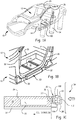
- a vehicle body 10 is shown.
- the vehicle body 10 defines an interior 12 and includes a plurality of structural members 14 one or more of which includes an energy absorbing device 100.
- the plurality of structural members 14 are arranged about the interior 12 of the vehicle body 10 and the interior 12 of the vehicle body 10 is configured to carry vehicle occupants and various vehicle components.
- the vehicle components are a battery 16 (shown in FIG. 1C ), which is carried within the vehicle body 10 in a battery compartment 18 located below the vehicle passenger compartment.
- the vehicle body 10 is a vehicle body for an electric or a hybrid-electric vehicle.
- other types of vehicles can also benefit from the present disclosure, such as vehicles carrying internal combustion engines by way of non-limiting example.
- the plurality of structural members 14 include a tunnel member 20, a floor rocker 22, and a crossbar 24.
- the plurality of structural members 14 also includes a pillar 26, a roof rail 28 (shown in FIG. 1A ), and a rail extension 30.
- the tunnel member 20 extends longitudinally along a length of the vehicle body 10 and along the centerline of the vehicle body 10.
- the floor rocker 22 extends longitudinally along the vehicle body 10 and is substantially parallel to the tunnel member 20.
- the crossbar 24 extends laterally across the vehicle body 10 and between the tunnel member 20 and the floor rocker 22, the floor rocker 22 thereby supported by the crossbar 24 at longitudinal locations where the crossbar 24 abuts the floor rocker 22.
- the rail extension 30 couples the floor rocker 22 to the pillar 26, and pillar 26 extends upwards from the rail extension 30 to couple the roof rail 28 with the floor rocker 22. So connected the floor rocker 22, pillar 26 and the roof rail 28 extend about a door ring 32 disposed on a side of the vehicle body 10. So disposed the floor rocker 22 is positioned to oppose side impacts to the vehicle body 10 and in this respect is configured with strength sufficient to absorb energy and resist intrusion into the interior 12 of the vehicle body 10 during side impact events, such as a side pole impact 34.
- the floor rocker 22 is arranged laterally outboard of the tunnel member 20 and includes a plate member 36 and a facia member 38.
- the crossbar 24 extends between the plate member 36 and the tunnel member 20 and is laterally supported thereby.
- the facia member 38 is connected to the plate member 36 such that the plate member 36 and the facia member 38 define between one another a cavity 40.
- the energy absorbing device 100 is supported within the cavity 40, e.g., with a fastener, a clip, a bracket, and/or an adhesive, along a longitudinal axis 106.
- energy absorbing device 100 can also be employed in other structural members, such as one or more of the pillar 26 (shown in FIG. 1A ), the roof rail 28 (shown in FIG. 1A ), or the rail extension 30 (shown in FIG. 1B ), as suitable for an intended application.
- the longitudinal length of the structural members 14 is dependent upon the particular area of the vehicle body the hollow member is employed, while the length of the energy absorbing device 100 is dependent upon the amount and location of enhanced structural integrity in the hollow member.
- the honeycomb body can have a span commensurate with the longitudinal length of the hollow member or less than the longitudinal length of the hollow member component (e.g., can be localized; i.e., disposed only in a specific location to attain enhanced structural integrity of that location). Desirably, to maximize the weight reduction, the honeycomb body is localized so as to add the minimum amount of weight needed to attain a desired structural integrity (e.g., a structural integrity that this greater than or equal to the standard metal component without the thinner walls).
- a desired structural integrity e.g., a structural integrity that this greater than or equal to the standard metal component without the thinner walls.
- the honeycomb body can have a length of less than or equal to 1 meter, specifically, less than or equal to 800 millimeters, and more specifically, less than or equal to 300 millimeters.
- the length of the honeycomb body can be less than or equal to 80% of the length of the structural member, specifically, less than or equal to 60%, more specifically, less than or equal to 50%, and yet more specifically, 10% to 35% of the length of the structural member (i.e., the structural member reinforced by the honeycomb body).
- the honeycomb body can have a length of 150 millimeters to 350 millimeters, specifically, 200 millimeters to 250 millimeters, such as for use in a pillar or rail.
- the honeycomb body has a length of between about 500 millimeters and about 800 millimeters, specifically, 600 millimeters to 700 millimeters, such as for use in a floor rocker.
- the structural component is a hollow metal element.
- Some possible structural member material(s) include aluminum, titanium, chrome, magnesium, zinc, and steel, plastic (e.g., fiber reinforced plastic) as well as combinations comprising at least one of the foregoing materials.
- the thickness of the walls of the structural members 14 can all be the same or can be different to enhance stiffness in a desired direction. For example, one set of opposing walls can have a greater/lesser thickness than the other set of opposing walls.
- the structural members 14 have a wall thickness of less than or equal to 10 millimeters, specifically, 1.2 millimeters to 5 millimeters, and more specifically 1.8 millimeters to 4 millimeters.
- metal walls e.g., floor rocker, rails, pillars, bumper beam, and so forth
- wall thickness of the structural component
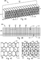
- the energy absorbing device 100 is shown. As shown in FIGS. 2A and 2B , the energy absorbing device 100 generally includes a honeycomb body 102 having a plurality of tubes 104 stacked transversely with one another along the longitudinal axis 106.
- the honeycomb body 102 has an inboard portion 108 (shown in FIG. 2B ) with an inboard portion bending stiffness 110 (shown in FIG. 2B ) and an outboard portion 112 (shown in FIG. 2B ) with an outboard portion bending stiffness 114 (shown in FIG. 2B ).
- the outboard portion 112 is arranged outboard of the longitudinal axis 106.
- the inboard portion 108 is arranged inboard of the outboard portion 112, is coupled to the outboard portion 112, and the illustrated implementation spans the longitudinal axis 106.
- the outboard portion bending stiffness 114 of the outboard portion 112 is greater than the inboard portion bending stiffness 110 of the inboard portion 108.
- the plurality of tubes 104 extend laterally between an outboard face 120 and an inboard face 122 of the energy absorbing device 100. More specifically, the plurality of tubes 104 span the honeycomb body 102 between the outboard face 120 of the honeycomb body 102 and the inboard face 122 of the honeycomb body 102.
- the inboard face 122 of the honeycomb body 102 opposes the plate member 36 (shown in FIG. 1C ) and the outboard face 120 of the honeycomb body 102 opposes the facia member 38. It is contemplated that inboard face 122 of the honeycomb body 102 further abut the plate member 36, e.g., be in intimate mechanical contact therewith, for communication for force associated with the side pole impact 34 (shown in FIG. 1A ) for energy absorption during the side pole impact 34 via crushing of the plurality of tubes 104 between the object impact and the plate member 36.
- the inboard profile 116 defined by the plurality of tubes 104 has a hexagonal shape 124 and the outboard profile 118 defined by the plurality of tubes has a hexagonal shape 126.
- wall thickness 130 of the honeycomb body 102 within the outboard portion 112 be greater than wall thickness 132 in the inboard portion 108, the wall thickness 130 imparting the outboard portion 112 with the outboard portion bending stiffness 114 greater than the inboard portion bending stiffness 110.
- Such wall thickness variation can be accomplished, for example, by forming the energy absorbing device 100 from a polymeric material 134 using an injection molding technique.
- the polymeric material 134 can include any thermoplastic material or combination of thermoplastic materials that can be formed into the desired shape and provide the desired properties, and may be filled or unfilled.
- suitable polymeric materials include thermoplastic materials as well as combinations of thermoplastic materials with metal, elastomeric material, and/or thermoset materials.
- thermoplastic materials include polybutylene terephthalate (PBT); acrylonitrile-butadiene-styrene (ABS); polycarbonate; polycarbonate/PBT blends; polycarbonate/ABS blends; copolycarbonate-polyesters; acrylic-styrene-acrylonitrile (ASA); acrylonitrile-(ethylene-polypropylene diamine modified)-styrene (AES); phenylene ether resins; blends of polyphenylene ether/polyamide; polyamides; phenylene sulfide resins; polyvinyl chloride PVC; high impact polystyrene (HIPS); low/high density polyethylene (L/HDPE); polypropylene (PP); expanded polypropylene (EPP); and thermoplastic olefins (TPO).
- PBT polybutylene terephthalate
- ABS acrylonitrile-butadiene-styrene
- ABS polycarbonate
- the plastic material can include a Noryl GTX® thermoplastic resin or a Xenoy® synthetic resin, each available from SABIC Global Technologies of Bergen op Zoom, Netherlands.
- the polymeric material 134 can also include combinations comprising one or more of the above-described polymeric materials.
- crushing sequences and section force vs time plots are shown for the energy absorbing device 100 and an energy absorbing device 50 having uniform bending stiffness through its depth.
- tubes forming the energy absorbing device 50 crush from both an outboard surface 52 and an inboard surface 54 towards the center of the energy absorbing device 50.
- the energy absorbing device 100 crushes from the inboard face 122 toward the outboard face 120 of the energy absorbing device 100. This causes the energy absorbing device 100 to exert section force responsive to the side pole impact 34 where section force peaks shortly after the beginning of the impact event, as shown in FIG. 3B with a trace 60.
- the peak section force 62 occurs about midway between the time T 1 and time T 2 , the section force trace 60 declining as the inboard portion 108 and the outboard portion 112 thereafter crush.
- the acceleration imparted to the vehicle occupants and/or vehicle components carried within the interior 12 of the vehicle body 10 is relatively low in comparison with that associated with the impact to the energy absorbing device 50.
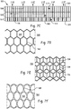
- an energy absorbing device 200 is shown.
- the energy absorbing device 200 is similar to the energy absorbing device 100 (shown in FIG. 1A ), and additionally includes an outboard profile 218 having a hexagonal shape 224 with a rib 250 arranged within the hexagonal shape 264 and an inboard profile 216 having a hexagonal shape 224 with no rib arranged within the hexagonal shape 226.
- the energy absorbing device 200 includes a honeycomb body 202.
- the honeycomb body 202 has a plurality of tubes 204 stacked transversely with one another along the longitudinal axis 106.
- the outboard portion 212 is arranged outboard of the longitudinal axis 106, is coupled to the inboard portion 108 of the honeycomb body 202, and has an outboard bending portion stiffness 214.
- the inboard portion 208 laterally spans the longitudinal axis 106.
- the plurality of tubes 204 extend laterally between an outboard face 220 and an inboard face 222 of the energy absorbing device 200. More specifically, the plurality of tubes 204 span the honeycomb body 202 between the outboard face 220 of the honeycomb body 202 and the inboard face 222 of the honeycomb body 202. It is contemplated that, when supported within the structural member 14 (shown in FIG, 1A ), e.g., the floor rocker 22 (shown in FIG. 1C ), the inboard face 222 of the honeycomb body 202 opposes the plate member 36 (shown in FIG. 1C ) and the outboard face 220 of the honeycomb body 202 opposes the facia member 38 (shown in FIG. 1C ).
- inboard face 222 of the honeycomb body 202 abut the plate member 36 (shown in FIG. 1C ) such that, responsive to the side pole impact 34 (shown in FIG. 1A ), the plurality of tubes 204 crush between the object responsible for the impact and the plate member 36 to absorb energy associated with the impact and limit acceleration imparted to vehicle occupants and vehicle components carried within the interior 12 of the vehicle body 10.
- the inboard profile 216 defined by the plurality of tubes 204 has a hexagonal shape 224.
- the outboard profile 218 defined by the plurality of tubes also has a hexagonal shape 226, the profile defined by each of the plurality of tubes 304 being continuous between the inboard face 222 and the outboard face 220 in this respect.
- the plurality of tubes 204 in the inboard portion 208 have no rib arranged within the respective tubes of the plurality of tubes 204.
- the plurality of tubes 204 have ribs 250 arranged therein, the ribs 250 render the outboard portion bending stiffness 214 (shown in FIG.
- the greater stiffness of the outboard portion 112 causes the energy absorbing device 200 to crush from the inboard face 222 to the outboard face 220.
- the greater stiffness of the outboard portion 112 also causes the energy absorbing device 200 to exert section force similar (or equivalent) to that of the energy absorbing device 100 insofar as the peak section force being generated closer to the onset of an impact, as shown in FIGS. 3A and 3B .
- the rib 250 is a y-rib. It is contemplated that other types of ribs can be employed, such as horizontal or vertical ribs, as suitable for an intended application.
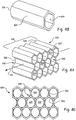
- an energy absorbing device 300 is shown.
- the energy absorbing device 300 is similar to the energy absorbing device 100 (shown in FIG. 1A ), and additionally includes an outboard profile 318 that is different than an inboard profile 316 of the energy absorbing device 300.
- the outboard profile 318 has a circular shape 326 and the inboard profile 316 has a hexagonal shape 324 (shown in FIG. 5C ).
- the energy absorbing device 300 includes a honeycomb body 302 having a plurality of tubes 304 stacked transversely with one another along the longitudinal axis 106.
- the honeycomb body 102 (shown in FIG. 5A ) has an inboard portion 308 and an outboard portion 312.
- the outboard portion 312 is arranged outboard of the longitudinal axis 106 and is coupled to the outboard portion 312.
- the inboard portion 308 has an inboard portion bending stiffness 310
- the outboard portion 312 has an outboard portion bending stiffness 314, and the outboard portion bending stiffness 314 of the outboard portion 312 is greater than the inboard portion bending stiffness 310 of the inboard portion 308.
- the circular shape 326 (shown in FIG. 5C ) of the plurality of tubes 304 in the outboard portion 312 impart to the outboard portion 312 greater bending stiffness than the hexagonal shape 324 (shown in FIG. 5D ) defined in the inboard portion 308.
- the plurality of tubes 304 extend laterally between an outboard face 320 and an inboard face 322 of the energy absorbing device 300. More specifically, the plurality of tubes 304 span the honeycomb body 302 between the outboard face 320 of the honeycomb body 302 and the inboard face 322 of the honeycomb body 302. The inboard face 322 of the honeycomb body 302 oppose the plate member 36 (shown in FIG. 1C ) and the outboard face 320 of the honeycomb body 302 oppose the facia member 38 (shown in FIG. 1C ). It is also contemplated that inboard face 322 of the honeycomb body 302 abut the plate member 36 (shown in FIG. 1C ) such that, responsive to the side pole impact 34 (shown in FIG. 1A ), the plurality of tubes 304 crush between the object exerting the impact force and the plate member 36.
- the inboard profile 316 defined by the plurality of tubes 304 has the hexagonal shape 324 and the outboard profile 318 defined by each of the plurality of tubes 304 has the circular shape 326. It is contemplated that the circular shape 326 render the outboard portion bending stiffness 314 (shown in FIG. 5B ) of the outboard portion 312 greater than the inboard portion bending stiffness 310 (shown in FIG. 5B ) of the inboard portion 308 of the honeycomb body 302.
- the shape difference in the shape defined by each of the plurality of tubes 304 in the inboard portion 308 and the outboard portion 312 causes the energy absorbing device 300 to crush and exert section force similar (or equivalent) to that of the energy absorbing device 100, as shown in FIGS. 3A and 3B .
- the circular shape 326 is oblong in the vertical direction (relative to gravity).
- the circular shape 326 can be symmetrical, oblong in the horizontal direction, or oblong in any orientation, as suitable for an intended application.
- an energy absorbing device 400 is shown.
- the energy absorbing device 400 is similar to the energy absorbing device 100 (shown in FIG. 1A ), and additionally includes an outboard profile 418 having a triangular shape 426.
- the energy absorbing device 400 includes a honeycomb body 402 having a plurality of tubes 404 stacked transversely with one another along the longitudinal axis 106.
- the honeycomb body 402 (shown in FIG. 5A ) has an inboard portion 408 and an outboard portion 412.
- the inboard portion is arranged along the longitudinal axis 106 and has an inboard portion bending stiffness 410.
- the outboard portion 412 is arranged outboard of the longitudinal axis 106, is coupled to the inboard portion 408, and has an outboard portion bending stiffness 414.
- the outboard portion bending stiffness 414 is greater than the inboard bending stiffness 410.
- the greater stiffness of the outboard portion 412 relative to the bending stiffness of the inboard portion 408 is imparted by the triangular shape 426 defined by the plurality of tubes 404 in the outboard portion of the energy absorbing device 400.
- the plurality of tubes 404 extend laterally between an outboard face 420 and an inboard face 422 of the energy absorbing device 400. More specifically, the plurality of tubes 404 span the honeycomb body 402 between the outboard face 420 of the honeycomb body 402 and the inboard face 422 of the honeycomb body 402. It is contemplated that the inboard face 422 of the honeycomb body 402 oppose the plate member 36 (shown in FIG. 1C ), and the outboard face 420 of the honeycomb body 402 additionally oppose the facia member 38 (shown in FIG. 1C ). It is also contemplated that inboard face 422 of the honeycomb body 402 abut the plate member 36 (shown in FIG. 1C ) such that, responsive to the side pole impact 34 (shown in FIG. 1A ), the plurality of tubes 404 crush between the object exerting the impact force and the plate member 36.
- the inboard profile 416 defined by the plurality of tubes 404 has a hexagonal shape 424 and the outboard profile 418 defined by the plurality of tubes has a triangular shape 426.
- the triangular shape 426 causes the outboard portion bending stiffness 414 (shown in FIG. 5B ) to be greater than the inboard bending stiffness 410.
- the outboard portion bending stiffness 414 causes the energy absorbing device 400 to crush and exert section force similar (or equivalent) to that of the energy absorbing device 100, as shown in FIGS. 3A and 3B , the energy absorbing device 400 exerting peak section force closer to the beginning of an impact than the end of the impact and thereby limiting accelerations to vehicle occupants and vehicle components carried by the vehicle body 10.
- an energy absorbing device 500 is shown.
- the energy absorbing device 500 is similar to the energy absorbing device 100 (shown in FIG. 1A ) and additionally includes an intermediate portion 550.
- the energy absorbing device 500 includes a honeycomb body 502 having a plurality of tubes 504 stacked transversely with one another along the longitudinal axis 106.
- the honeycomb body 502 includes an inboard portion 508 arranged along the longitudinal axis 106 and having an inboard portion bending stiffness 510, an outboard portion 512 arranged outboard of the longitudinal axis 106, and the intermediate portion 550.
- the outboard portion 512 has an outboard portion bending stiffness 514, which is greater than the inboard portion bending stiffness 510, and is coupled to the inboard portion 508 by the intermediate portion 550.
- the intermediate portion 550 has an intermediate portion bending stiffness 552 that is less than the outboard portion bending stiffness 514 of the outboard portion 512. This a stepwise graduation to the bending stiffness of the honeycomb body 502 along the depth of the energy absorbing device 500.
- Each of the plurality of tubes 504 of the honeycomb body 502 spans the inboard portion 508, the intermediate portion 550, and the outboard portion 512 of the honeycomb body 502.
- each of the plurality of tubes 504 extend between an inboard face 522 and an outboard face 520 of the energy absorbing device 500.
- the energy absorbing device 500 can be supported within the floor rocker 22 (shown in FIG. 1B ) such that ends of the plurality of tubes 504 abut the plate member 36 (shown in FIG. 1C ) for crushing against the plate member 36 during a side impact, e.g., the side pole impact 34 (shown in FIG. 1A ).
- the honeycomb body 502 is constructed using a polymeric material, e.g., the polymeric material 134 (shown in FIG. 2A ), using an injection molding technique.
- the honeycomb body 502 is constructed using an additive manufacturing technique.
- forming the energy absorbing device 500 using an additive manufacturing techniques allows for forming the honeycomb body 502 with structures within the intermediate portion 550 that are prohibitively expensive (or mechanically not possible) using injection molding techniques, e.g., the ribs 558 (shown in FIG. 7E ), allowing the intermediate portion 550 to be relative stiff without otherwise increasing depth of the intermediate portion 550.
- each of the plurality of tubes 504 defines a profile in the intermediate portion 550 that is different than a profile defined by the tube in the inboard portion 508 and the outboard portion 512.
- each of the plurality of tubes 504 defines a profile 554 in the intermediate portion 550 having a hexagonal shape 556 with a rib 558 arranged therein, a profile 560 in the inboard portion 508 having a hexagonal shape 562 with no rib, and a profile 564 in the outboard portion 512 having a profile 566 with a circular shape 568.
- each of the inboard portion 508, and the intermediate portion 550, and the outboard portion 512 provide a graduated bending stiffness between the inboard face 522 and the outboard face 520 of the energy absorbing device 500 - allowing for tuning bending stiffness of the energy absorbing device 500 along the depth of the energy absorbing device 500.
- FIGS. 7A-7F a specific selection of shapes is shown in FIGS. 7A-7F , it is to be understood and appreciated that other shapes can be define within one (or more) of the inboard portion 508, the outboard portion 512, and/or the intermediate portion 550, such as triangular or square shapes, and remain within the scope of the present disclosure.
- the energy absorbing device 600 is similar to the energy absorbing device 100 (shown in FIG. 1A ) and additionally includes a honeycomb body 602.
- the honeycomb body 602 has a plurality of tubes 604 that vary continuously in shape between an inboard profile 650 and an outboard profile 652 of the each of the plurality of tubes 604. In this respect, as shown in FIG.
- the honeycomb body 602 defines an inboard profile 616 wherein the plurality of tubes 604 define a hexagonal shape 654, e.g., an opening on an inboard face 622 with the hexagonal shape 654, an outboard profile 618 wherein the plurality of tubes 604 define a circular shape 656, an opening on an outboard face 620 with the circular shape 656.
- progressive thickening of the tube walls along depths of the plurality of tube 604 between the inboard face 622 and the outboard face 620 changes the bending stiffness of the energy absorbing device 600 continuous through the depth of the energy absorbing device 600. This allows the change in bending stiffness between the inboard face 622 and the outboard face 620 to be selected by both profile shape selection as well as the rate of change in thickness of the walls of the plurality of tubes 604.
- an energy absorbing device 700 is shown.
- the energy absorbing device 700 is similar to the energy absorbing device 100 (shown in FIG. 1A ).
- the energy absorbing device 700 has a honeycomb body 702 having a plurality of tubes 704, an inboard portion 708, and an outboard portion 112.
- the inboard portion 708 is arranged along the longitudinal axis 106 and has an inboard bending stiffness 710.
- the outboard portion is arranged outboard of the longitudinal axis 106, is coupled to the inboard portion 708, and has an outboard bending stiffness 714.
- the outboard bending stiffness 714 is greater than the inboard bending stiffness 710 and additionally that varies along the longitudinal axis 106 according to transition depth 701 within the energy absorbing device 700.
- the honeycomb body 702 has a first segment 750 and a second segment 752.
- the second segment 752 is coupled to the first segment 750, is axially offset from the first segment 750 along the longitudinal axis 106, and has outboard portion bending stiffness 760 that is greater than outer portion bending stiffness 762 in the first segment 750.
- bending stiffness of the energy absorbing device 700 changes according to location of the transition depth 701 along the longitudinal axis 106 within the honeycomb body 702. In the illustrated implementation the transition depth varies continuously between longitudinally opposite ends according to a second order function.
- bending stiffness can be selected at various longitudinal positions according to the support provided by structural members 14 (shown in FIG. 1A ) forming the vehicle body 10 (shown in FIG. 1 ).
- the first segment 750 can be located at longitudinal position wherein the crossbar 24 abuts the energy absorbing device 700.
- the energy absorbing device 700 to be relatively lightweight in comparison to energy absorbing devices constructed with uniform bending stiffness along their longitudinal length, e.g., the energy absorbing device 50 (shown in FIG. 3A ), owing to the employment of a lighter construction at locations abutting the crossbar 24.
- FIG. 10A it also allows the peak section force 70 generated by the energy absorbing device 700 to vary according to longitudinal position along the length of the energy absorbing device 700.
- the plurality of tubes 704 forming the honeycomb body 702 define a hexagonal shape 754 and a hexagonal shape 756 in both the inboard portion 708 and the outboard portion 712 of the honeycomb body 702.
- Depth 758 of the outboard portion 712 and the inboard portion 708 changes according to longitudinal position. It is contemplated that, in certain implementations, the ratio of the outboard portion depth 758 to the total section depth 760 be selected to limit weight according to support (or absence of support) provided by the crossbar 24 (shown in FIG. 1B ) as well as other structure members, e.g., the structural members 14 (shown in FIG. 1A ), forming the vehicle body 10 (shown in FIG. 1A ).
- an energy absorbing device 800 is shown.
- the energy absorbing device 800 is similar to the energy absorbing device 700 (shown in FIG. 9A ), and additionally includes a honeycomb body 802 having a plurality of tubes 804 with ribs 850 arranged within the plurality of tubes 804.
- the ribs 850 are arranged within an outboard portion 812 (shown in FIG. 11B ) of honeycomb body 802 and extend into the honeycomb body to respective depths that vary according to longitudinal position along the longitudinal axis 106. As shown in FIG.
- the plurality of tubes 804 define a hexagonal shape 852 in the outboard portion 812 of the honeycomb body 802 and a hexagonal shape 854 in an inboard portion 808 of the honeycomb body 802.
- a particular rib structure e.g., the rib 850
- FIGS. 11A and FIG. 11B it is to be understood and appreciated that rib structures of other shapes can be disposed within the plurality of tubes 804, and truncated with respect to the depth of the plurality of tubes 804, to impart the desired crushing resistance of the honeycomb body 802.
- an energy absorbing device 900 is shown.
- the energy absorbing device 900 is similar to the energy absorbing device 700 (shown in FIG. 9A ), and additionally includes a honeycomb body 902 having a plurality of tubes 904 defining a circular shape 950 in an outboard portion 912 of the honeycomb body 902 and a hexagonal shape 952 in an inboard portion 908 of the honeycomb body 902.
- the depth at which the plurality of tubes 904 transition differs according to longitudinal position to define a ratio of an outer portion depth 954 to total section depth 956 according to the support provided by the crossbar 24 (shown in FIG. 1B ), enabling tuning and limiting weight of the energy absorbing device 900.
- Tubes with a circular shape impart the portion of the honeycomb body 902 having the tubes with greater crush resistance than honeycomb portions with the same inscribed dimension and having a finite number of sides, allowing the portion to preferentially crush subsequent to portions having profiles with a finite number of sides.
- an energy absorbing device 1000 is shown.
- the energy absorbing device 1000 is similar to the energy absorbing device 700 (shown in FIG. 9A ), and additionally includes a honeycomb body 1002 having a plurality of tubes 1004 defining a triangular shape 1050 in an outboard portion 1012 of the honeycomb body 1002 and a hexagonal shape 1052 in an inboard portion 1008 of the honeycomb body 1002.
- the depth at which the plurality of tubes 904 transition differs according to longitudinal position to define a ratio of an outer portion depth 1054 to total section depth 1056 according to the support provided by the crossbar 24 (shown in FIG. 1B ), enabling tuning and limiting weight of the energy absorbing device 1000.
- Tubes with a triangular shape impart the portion of the honeycomb body 1002 having the tubes with less crush resistance than honeycomb portions with the same inscribed dimension and having a greater number of sides, allowing the portion to preferentially crush prior to portions having profiles with more than three sides.
- compositions, methods, and articles can alternatively comprise, consist of, or consist essentially of, any appropriate materials, steps, or components herein disclosed.
- the compositions, methods, and articles can additionally, or alternatively, be formulated so as to be devoid, or substantially free, of any materials (or species), steps, or components, that are otherwise not necessary to the achievement of the function or objectives of the compositions, methods, and articles.
- test standards are the most recent standard in effect as of the filing date of this application, or, if priority is claimed, the filing date of the earliest priority application in which the test standard appears.
Abstract
Description
- The present disclosure generally relates to energy absorbing devices for vehicle bodies, and more particularly to energy absorbing devices having bending stiffness that varies along either or both the depth and longitudinal length of the energy absorbing device.
- Automotive manufactures are continuing to reduce the weight of passenger vehicles to meeting governmental regulations relating to fuel efficiency and emissions. Since the metal structure of the vehicle structure, e.g., the 'body-in white", typically forms a significant portion of the total weight of a vehicle, reducing the amount of steel employed in the vehicle structure can improve the fuel efficiency and emissions of the vehicle. However, reducing vehicle structure weight by substituting lighter materials, such as aluminum and plastics, for steel generally entails a trade-off with body stiffness, which is a key characteristic that influences vehicle dynamics, durability, and crashworthiness. Vehicle designers are therefore typically limited in the extent to which lightweight materials may be employed for weight in structures that contribute to stiffness of the vehicle structure. This generates a need for vehicle structures having reduced weight that do not adversely affect the dynamics, durability, and/or crashworthiness of the vehicle structure.
- Such energy absorbing devices, structural members, and vehicle bodies have generally been acceptable for their intended purpose. However, there remains a need in the art for improved energy absorbing devices, structural members, and vehicle bodies. The present disclosure provides a solution to this need.
- An energy absorbing device includes a honeycomb body having two or more tubes stacked transversely with one another along a longitudinal axis. The honeycomb body includes an inboard portion and an outboard portion. The inboard portion of the honeycomb body is arranged along the longitudinal axis and has an inboard portion bending stiffness. The outboard portion of the honeycomb body is arranged outboard of the longitudinal axis, is coupled to the inboard portion of the honeycomb body, and has an outboard portion bending stiffness. The outboard portion bending stiffness of the outboard portion is greater than the inboard portion bending stiffness of the inboard portion.
- A structural member for a vehicle body comprising a plate member; a facia member connected to the plate member, the facia member the plate member defining therebetween a cavity; and an energy absorbing device as described above supported within the cavity. The inboard portion of the honeycomb body abuts the plate member, wherein the honeycomb further comprises an intermediate portion coupling the inboard portion of the honeycomb body with the outboard portion of the honeycomb body, wherein the intermediate portion has an intermediate portion bending stiffness, the intermediate portion bending stiffness less than the outboard portion bending stiffness of the honeycomb body.
- A vehicle body comprising a structural member selected from a group including a pillar, a floor rocker, a roof rail, a rail extension, and a bumper beam, the structural member comprising a plate member; a facia member connected to the plate member, the facia member the plate member defining therebetween a cavity; and an energy absorbing device as described above supported within the cavity, the inboard portion of the honeycomb body abutting the plate member. The honeycomb body further comprises a first segment with a first segment bending stiffness, a second segment connected to the first segment and axially offset therefrom along the longitudinal axis, the second segment having a second segment stiffness that is greater than first segment bending stiffness; and a support member abutting the plate member at location adjacent to the first segment of the energy absorbing device, wherein no support member abuts the plate member at a location adjacent to the second segment of the energy absorbing device
- The above described and other features are exemplified by the following figures and detailed description.
- The following figures are exemplary implementations wherein the like elements are numbered alike.
-
FIGS. 1A-C are full perspective, partial perspective, and partial sectional views of an energy absorbing device constructed in accordance with the present disclosure, showing a vehicle body having structural members with the energy absorbing member supported within the structural member, respectively; -
FIGS. 2A-2D are perspective, plan, and partial sectional views of the energy absorbing device ofFIG. 1A according to an implementation, showing inboard and outboard portions of a honeycomb body having a plurality of tubes defining hexagonal shapes, respectively; -
FIGS. 3A and3B are time sequence diagrams and a chart of the energy absorbing device ofFIG. 1A undergoing a side pole impact, showing the energy absorbing device progressively crushing from an inboard face to an outboard face and exerting a section force than peaks early in the impact, respectively; -
FIGS. 4A-4D are perspective, plan, and partial sectional views of the energy absorbing device ofFIG. 1A according to another implementation, showing an energy absorbing device having an outboard portion with a rib, respectively; -
FIGS. 5A-5D are perspective, plan, and partial sectional views of the energy absorbing device ofFIG. 1A according to a further implementation, showing an energy absorbing device having an outboard portion having tubes that define circular shapes, respectively; -
FIGS. 6A-6D are perspective, plan, and partial sectional views of the energy absorbing device ofFIG. 1A according to yet another implementation, showing an energy absorbing device having an outboard portion having tubes that define triangular shapes, respectively; -
FIGS. 7A-7F are perspective, plan, and partial sectional views of the energy absorbing device ofFIG. 1A , showing an implementation having an intermediate segment, wherein tubes define a shape in the intermediate segment that is different than that defined by the tubes in the inboard portion and in the outboard portion, respectively; -
FIGS. 8A-8C are partial perspective and partial elevation views of the energy absorbing device ofFIG. 1A , showing an implementation wherein the plurality tubes define different shapes at the inboard face and the outboard, the varying continuously in shape between the inboard face and the outboard face; -
FIGS. 9A and 9B are perspective and plan views of an energy absorbing device according a further implementation of the energy absorbing device ofFIG. 1A , showing an energy absorbing device having outboard portion bending stiffness that varies along the longitudinal length of the energy absorbing device, respectively; -
FIGS. 10A and 10B are a graph of section force by longitudinal position and a schematic view of a portion of the vehicle body supporting the energy absorbing device, showing section force varying according to longitudinal position and cooperating with support provided by the crossbar of the vehicle structure, respectively; -
FIGS. 11A and 11B are perspective and plan views of an energy absorbing device according a further implementation of the energy absorbing device ofFIG. 9A and 9B , showing an energy absorbing device having outboard portion bending stiffness that varies along the longitudinal length of the energy absorbing device according to the depth of ribs arranged within the outer portion of the honeycomb body, respectively; -
FIGS. 12A and 12B are perspective and plan views of an energy absorbing device according a further implementation of the energy absorbing device ofFIG. 9A and 9B , showing an energy absorbing device having outboard portion bending stiffness that varies along the longitudinal length of the energy absorbing device according to the depth of circular profiles defined by the outer portion of the honeycomb body, respectively; and -
FIGS. 13A and 13B are perspective and plan views of an energy absorbing device according a further implementation of the energy absorbing device ofFIG. 9A and 9B , showing an energy absorbing device having outboard portion bending stiffness that varies along the longitudinal length of the energy absorbing device according the depth of triangular profiles defined by the outer portion of the honeycomb body, respectively; - During side impact the structural members forming the vehicle body, e.g., floor rockers, pillars, roof rails, and crossbars, typically absorb the majority energy associated with the impact. As mentioned above, it is desirable to reduce the weight of a vehicle without compromising the strength, durability, and/or crashworthiness of the vehicle body. Therefore, it is desirable to reduce the amount of metal forming the vehicle body while not sacrificing strength. Employed throughout the vehicle are structural members , e.g., roof rails, pillars, rockers, rail extensions, and/or crossbars, which are typically hollow and are formed from sheet metal. The thickness and shape of the sheet metal forming these hollow structures members is typically selected to provide strength sufficient for durability and crashworthiness of the vehicle. It has been discovered that the thickness of the sheet forming such structural members can be reduced, thereby reducing the weight of the structural member and hence the vehicle body formed by the structural member(s), while retaining the strength of the structural member by incorporating an energy absorbing device within the structural member.
- In implementations described herein, structural members have supported therein energy absorbing devices members having polymeric bodies arranged for controlled crushing. The controlled crushing is provided by varying the bending stiffness within the depth of the energy absorbing device, e.g., in a direction orthogonal relative to the longitudinal axis of the energy absorbing device. More specifically, the energy absorbing devices are arranged such that the inboard portion of the honeycomb body included in the energy absorbing device crushes prior to the outboard portion of the honeycomb body. This causes the section force exerted by the honeycomb body to peak closer to the start of the impact than the end of the impact, and in certain implementations, prior to the loss of stiffness in the honeycomb member in response to an impact. This limits the acceleration imparted upon vehicle occupants and/or vehicle components carried within the interior of the vehicle body, limiting damage. In the case of electric and/or hybrid-electric vehicles carrying batteries below the vehicle floor, such energy absorbing devices can limit the tendency of the object responsible for the impact from intruding into the battery compartment, reducing (or eliminating entirely) the likelihood of damage to the battery as a consequence of the impact. As such, the overall weight of a vehicle can be reduced without reduction of strength or otherwise potentially limit the crashworthiness of the vehicle body.
- In certain implementations energy absorbing devices described herein can have bending stiffness that varies along the longitudinal length of the energy absorbing member. For example, the energy absorbing device can have relatively low bending stiffness at locations where the energy absorbing member receives directly receives support from a crossbar or other structural member, and the energy absorbing member can have relatively high bending stiffness at longitudinal locations where the energy absorbing member is indirectly supported by the crossbar or other structural member. Such stiffness control allows the energy absorbing member to have be lightweight in comparison to energy absorbing members having uniform bending stiffness along the longitudinal length of the energy absorbing member. As such, the overall weight of a vehicle can be further reduced without reduction of strength or otherwise potentially limit the crashworthiness of the vehicle body.
- The energy absorbing device includes a honeycomb body with a plurality if tubes stacked transversely with one another along a longitudinal axis. The honeycomb body includes an inboard portion and an outboard portion. The inboard axis is arranged along the longitudinal axis and has an inboard portion bending stiffness. The outboard portion is outboard of the inboard portion along the longitudinal axis, the outboard portion coupled to the inboard portion and having an outboard portion bending stiffness. The outboard portion bending stiffness is greater than the inboard portion bending stiffness.
- The honeycomb body can include a plurality of transversely stacked tubes having a single cross-sectional shape. The cross-sectional shape can be selected from a group includes triangles, squares, hexagons, and circles. A depth defined by the plurality of tubes can be substantially uniform along a longitudinal span of the honeycomb body. It is also contemplated that a depth of the plurality of tubes defined by the cross-sectional shape can vary along the longitudinal span of the honeycomb body. Further, in accordance with certain implementations, the plurality of tubes of the honeycomb body can have two or more cross-sectional shapes. The cross-sectional shapes can be selected from the group including triangles, squares, hexagons, and circles. Depths of the two or more cross-sectional shapes can be uniform along the longitudinal span of the honeycomb body. Depths of the two or more cross-sectional shapes can vary along the longitudinal span of the honeycomb body.
- The plurality of the tubes of the honeycomb body can have a y-rib or a vertical rib within an interior of the respective tube. In certain implementations the y-rib or the vertical rib can span the depth of the respective tube. In accordance with certain implementations the y-rib or the vertical rib can span one a portion of the depth of the respective tube. The depth the y-rib or the vertical rib extends within the plurality of tubes can be uniform along the longitudinal span of the honeycomb body. The depth the y-rib or the vertical rib extends within the plurality of tubes can vary along the longitudinal span of the honeycomb body.
- The honeycomb body can have an intermediate portion coupling the inner portion of the honeycomb body to the outer portion of the honeycomb body. The intermediate portion can have an intermediate portion crush resistance, the intermediate portion crush resistance can be greater than the inner portion crush resistance, and the intermediate portion crush resistance can be smaller than the outer portion crush resistance. In certain implementations the intermediate portion crush resistance can be smaller than the inner portion crush resistance and the intermediate portion crush resistance can be greater than the outer portion crush resistance. In accordance with certain implementations the intermediate portion crush resistance can be constant along the longitudinal span of the honeycomb body. It is also contemplated that the intermediate portion crush resistance can vary varies along the longitudinal span of the honeycomb body.
- The plurality of tubes forming one of the inner portion, the outer portion, and the intermediate portion of the honeycomb body can have a cross-sectional shape that is different from a cross-sectional shape of another of the inner portion, the outer portion, and the intermediate portion of the honeycomb body. For example, the plurality of tubes forming the inner portion of the honeycomb body can have a hexagonal cross-sectional shape, the plurality of tubes forming the intermediate portion of the honeycomb body have a hexagonal cross-sectional shape with a y-rib extending along a depth of the intermediate portion, and the plurality of tubes forming the outer portion of the honeycomb body can have a circular cross-sectional shape. In certain implementations the honeycomb body can be formed using an injection molding technique. In accordance with certain implementations the honeycomb body can be formed using an additive manufacturing technique.
- A more complete understanding of the components, processes, and apparatuses disclosed herein can be obtained by reference to the accompanying drawings. These FIGS. (also referred to herein as "FIG.") are merely schematic representations based on convenience and the ease of demonstrating the present disclosure, and are, therefore, not intended to indicate relative size and dimensions of the devices or components thereof and/or to define or limit the scope of the exemplary implementations. Although specific terms are used in the following description for the sake of clarity, these terms are intended to refer only to the particular structure of the implementations selected for illustration in the drawings, and are not intended to define or limit the scope of the disclosure. In the drawings and the following description below, it is to be understood that like numeric designations refer to components of like function.
- Referring to
FIG. 1A , avehicle body 10 is shown. Thevehicle body 10 defines an interior 12 and includes a plurality ofstructural members 14 one or more of which includes anenergy absorbing device 100. The plurality ofstructural members 14 are arranged about the interior 12 of thevehicle body 10 and the interior 12 of thevehicle body 10 is configured to carry vehicle occupants and various vehicle components. Among the vehicle components are a battery 16 (shown inFIG. 1C ), which is carried within thevehicle body 10 in abattery compartment 18 located below the vehicle passenger compartment. In certain implementations thevehicle body 10 is a vehicle body for an electric or a hybrid-electric vehicle. However, as will be appreciated by those of skill in the art in view of the present disclosure, other types of vehicles can also benefit from the present disclosure, such as vehicles carrying internal combustion engines by way of non-limiting example. - With reference to
FIG. 1B , the plurality ofstructural members 14 include atunnel member 20, afloor rocker 22, and acrossbar 24. The plurality ofstructural members 14 also includes apillar 26, a roof rail 28 (shown inFIG. 1A ), and arail extension 30. Thetunnel member 20 extends longitudinally along a length of thevehicle body 10 and along the centerline of thevehicle body 10. Thefloor rocker 22 extends longitudinally along thevehicle body 10 and is substantially parallel to thetunnel member 20. Thecrossbar 24 extends laterally across thevehicle body 10 and between thetunnel member 20 and thefloor rocker 22, thefloor rocker 22 thereby supported by thecrossbar 24 at longitudinal locations where thecrossbar 24 abuts thefloor rocker 22. Therail extension 30 couples thefloor rocker 22 to thepillar 26, andpillar 26 extends upwards from therail extension 30 to couple theroof rail 28 with thefloor rocker 22. So connected thefloor rocker 22,pillar 26 and theroof rail 28 extend about adoor ring 32 disposed on a side of thevehicle body 10. So disposed thefloor rocker 22 is positioned to oppose side impacts to thevehicle body 10 and in this respect is configured with strength sufficient to absorb energy and resist intrusion into the interior 12 of thevehicle body 10 during side impact events, such as aside pole impact 34. - With reference to
FIG. 1C , portions of thevehicle body 10 and thefloor rocker 22 are shown. Thefloor rocker 22 is arranged laterally outboard of thetunnel member 20 and includes aplate member 36 and afacia member 38. Thecrossbar 24 extends between theplate member 36 and thetunnel member 20 and is laterally supported thereby. Thefacia member 38 is connected to theplate member 36 such that theplate member 36 and thefacia member 38 define between one another acavity 40. Theenergy absorbing device 100 is supported within thecavity 40, e.g., with a fastener, a clip, a bracket, and/or an adhesive, along alongitudinal axis 106. Although described herein in the context of thefloor rocker 22 it is to be understood and appreciated thatenergy absorbing device 100 can also be employed in other structural members, such as one or more of the pillar 26 (shown inFIG. 1A ), the roof rail 28 (shown inFIG. 1A ), or the rail extension 30 (shown inFIG. 1B ), as suitable for an intended application. - The longitudinal length of the
structural members 14 is dependent upon the particular area of the vehicle body the hollow member is employed, while the length of theenergy absorbing device 100 is dependent upon the amount and location of enhanced structural integrity in the hollow member. The honeycomb body can have a span commensurate with the longitudinal length of the hollow member or less than the longitudinal length of the hollow member component (e.g., can be localized; i.e., disposed only in a specific location to attain enhanced structural integrity of that location). Desirably, to maximize the weight reduction, the honeycomb body is localized so as to add the minimum amount of weight needed to attain a desired structural integrity (e.g., a structural integrity that this greater than or equal to the standard metal component without the thinner walls). The honeycomb body can have a length of less than or equal to 1 meter, specifically, less than or equal to 800 millimeters, and more specifically, less than or equal to 300 millimeters. The length of the honeycomb body can be less than or equal to 80% of the length of the structural member, specifically, less than or equal to 60%, more specifically, less than or equal to 50%, and yet more specifically, 10% to 35% of the length of the structural member (i.e., the structural member reinforced by the honeycomb body). For example, the honeycomb body can have a length of 150 millimeters to 350 millimeters, specifically, 200 millimeters to 250 millimeters, such as for use in a pillar or rail. In other implementations, the honeycomb body has a length of between about 500 millimeters and about 800 millimeters, specifically, 600 millimeters to 700 millimeters, such as for use in a floor rocker. The structural component is a hollow metal element. - Some possible structural member material(s) include aluminum, titanium, chrome, magnesium, zinc, and steel, plastic (e.g., fiber reinforced plastic) as well as combinations comprising at least one of the foregoing materials. The thickness of the walls of the
structural members 14 can all be the same or can be different to enhance stiffness in a desired direction. For example, one set of opposing walls can have a greater/lesser thickness than the other set of opposing walls. In some implementations, thestructural members 14 have a wall thickness of less than or equal to 10 millimeters, specifically, 1.2 millimeters to 5 millimeters, and more specifically 1.8 millimeters to 4 millimeters. Generally, metal walls (e.g., floor rocker, rails, pillars, bumper beam, and so forth), have a wall thickness of greater than 1.8 millimeters. Therefore, the use of theenergy absorbing device 100 enables reduction in wall thickness (of the structural component) of greater than or equal to 10%, specifically, greater than or equal to 20%, and even greater than or equal to 25%. - With reference to
FIGS. 2A-2D , theenergy absorbing device 100 is shown. As shown inFIGS. 2A and 2B , theenergy absorbing device 100 generally includes ahoneycomb body 102 having a plurality oftubes 104 stacked transversely with one another along thelongitudinal axis 106. Thehoneycomb body 102 has an inboard portion 108 (shown inFIG. 2B ) with an inboard portion bending stiffness 110 (shown inFIG. 2B ) and an outboard portion 112 (shown inFIG. 2B ) with an outboard portion bending stiffness 114 (shown inFIG. 2B ). Theoutboard portion 112 is arranged outboard of thelongitudinal axis 106. Theinboard portion 108 is arranged inboard of theoutboard portion 112, is coupled to theoutboard portion 112, and the illustrated implementation spans thelongitudinal axis 106. The outboardportion bending stiffness 114 of theoutboard portion 112 is greater than the inboardportion bending stiffness 110 of theinboard portion 108. - The plurality of
tubes 104 extend laterally between anoutboard face 120 and aninboard face 122 of theenergy absorbing device 100. More specifically, the plurality oftubes 104 span thehoneycomb body 102 between theoutboard face 120 of thehoneycomb body 102 and theinboard face 122 of thehoneycomb body 102. Theinboard face 122 of thehoneycomb body 102 opposes the plate member 36 (shown inFIG. 1C ) and theoutboard face 120 of thehoneycomb body 102 opposes thefacia member 38. It is contemplated thatinboard face 122 of thehoneycomb body 102 further abut theplate member 36, e.g., be in intimate mechanical contact therewith, for communication for force associated with the side pole impact 34 (shown inFIG. 1A ) for energy absorption during theside pole impact 34 via crushing of the plurality oftubes 104 between the object impact and theplate member 36. - As shown in
FIG. 2C and 2D , theinboard profile 116 defined by the plurality oftubes 104 has ahexagonal shape 124 and theoutboard profile 118 defined by the plurality of tubes has ahexagonal shape 126. It is contemplated thatwall thickness 130 of thehoneycomb body 102 within theoutboard portion 112 be greater thanwall thickness 132 in theinboard portion 108, thewall thickness 130 imparting theoutboard portion 112 with the outboardportion bending stiffness 114 greater than the inboardportion bending stiffness 110. Such wall thickness variation can be accomplished, for example, by forming theenergy absorbing device 100 from apolymeric material 134 using an injection molding technique. - The
polymeric material 134 can include any thermoplastic material or combination of thermoplastic materials that can be formed into the desired shape and provide the desired properties, and may be filled or unfilled. Examples of suitable polymeric materials include thermoplastic materials as well as combinations of thermoplastic materials with metal, elastomeric material, and/or thermoset materials. Possible thermoplastic materials include polybutylene terephthalate (PBT); acrylonitrile-butadiene-styrene (ABS); polycarbonate; polycarbonate/PBT blends; polycarbonate/ABS blends; copolycarbonate-polyesters; acrylic-styrene-acrylonitrile (ASA); acrylonitrile-(ethylene-polypropylene diamine modified)-styrene (AES); phenylene ether resins; blends of polyphenylene ether/polyamide; polyamides; phenylene sulfide resins; polyvinyl chloride PVC; high impact polystyrene (HIPS); low/high density polyethylene (L/HDPE); polypropylene (PP); expanded polypropylene (EPP); and thermoplastic olefins (TPO). For example, the plastic material can include a Noryl GTX® thermoplastic resin or a Xenoy® synthetic resin, each available from SABIC Global Technologies of Bergen op Zoom, Netherlands. Thepolymeric material 134 can also include combinations comprising one or more of the above-described polymeric materials. - With reference to
FIGS. 3A and3B , crushing sequences and section force vs time plots are shown for theenergy absorbing device 100 and anenergy absorbing device 50 having uniform bending stiffness through its depth. As shown on the left-hand side ofFIG. 3A (relative to the top of the drawing figure), tubes forming theenergy absorbing device 50 crush from both anoutboard surface 52 and aninboard surface 54 towards the center of theenergy absorbing device 50. This cause the section force exerted by theenergy absorbing device 50 to be relatively consistent between times T2 and T4 as the tubes forming theenergy absorbing device 50 crush from bothinboard face 52 and theoutboard face 54 toward thecenter 56 of theenergy absorbing device 50, as shown inFIG. 3B with thesection force trace 58. - In contrast, as shown on the right-hand side of
FIG. 3A (relative to the top of the drawing figure), theenergy absorbing device 100 crushes from theinboard face 122 toward theoutboard face 120 of theenergy absorbing device 100. This causes theenergy absorbing device 100 to exert section force responsive to theside pole impact 34 where section force peaks shortly after the beginning of the impact event, as shown inFIG. 3B with atrace 60. In the illustrated implementation thepeak section force 62 occurs about midway between the time T1 and time T2, thesection force trace 60 declining as theinboard portion 108 and theoutboard portion 112 thereafter crush. As a consequence the acceleration imparted to the vehicle occupants and/or vehicle components carried within theinterior 12 of thevehicle body 10 is relatively low in comparison with that associated with the impact to theenergy absorbing device 50. In vehicles carrying batteries, e.g., the battery 16 (shown inFIG. 1C ), this reduces the likelihood of the battery fracturing. It also limits the distance the impacting object intrudes into the interior 12 of thevehicle body 10, as shown inFIG. 3A by the comparative amounts of deflection shown at time T4 on both the left-hand and right-hand sides of the figure. - With reference to
FIGS. 4A-4D , anenergy absorbing device 200 is shown. Theenergy absorbing device 200 is similar to the energy absorbing device 100 (shown inFIG. 1A ), and additionally includes anoutboard profile 218 having ahexagonal shape 224 with arib 250 arranged within the hexagonal shape 264 and aninboard profile 216 having ahexagonal shape 224 with no rib arranged within thehexagonal shape 226. As shown inFIG. 4A , theenergy absorbing device 200 includes ahoneycomb body 202. Thehoneycomb body 202 has a plurality oftubes 204 stacked transversely with one another along thelongitudinal axis 106. - As shown in
FIG. 4B , theoutboard portion 212 is arranged outboard of thelongitudinal axis 106, is coupled to theinboard portion 108 of thehoneycomb body 202, and has an outboardbending portion stiffness 214. In the illustrated implementation theinboard portion 208 laterally spans thelongitudinal axis 106. - The plurality of
tubes 204 extend laterally between anoutboard face 220 and aninboard face 222 of theenergy absorbing device 200. More specifically, the plurality oftubes 204 span thehoneycomb body 202 between theoutboard face 220 of thehoneycomb body 202 and theinboard face 222 of thehoneycomb body 202. It is contemplated that, when supported within the structural member 14 (shown inFIG, 1A ), e.g., the floor rocker 22 (shown inFIG. 1C ), theinboard face 222 of thehoneycomb body 202 opposes the plate member 36 (shown inFIG. 1C ) and theoutboard face 220 of thehoneycomb body 202 opposes the facia member 38 (shown inFIG. 1C ). It is contemplated thatinboard face 222 of thehoneycomb body 202 abut the plate member 36 (shown inFIG. 1C ) such that, responsive to the side pole impact 34 (shown inFIG. 1A ), the plurality oftubes 204 crush between the object responsible for the impact and theplate member 36 to absorb energy associated with the impact and limit acceleration imparted to vehicle occupants and vehicle components carried within theinterior 12 of thevehicle body 10. - As shown in
FIGS. 4C and 4D , theinboard profile 216 defined by the plurality oftubes 204 has ahexagonal shape 224. Theoutboard profile 218 defined by the plurality of tubes also has ahexagonal shape 226, the profile defined by each of the plurality oftubes 304 being continuous between theinboard face 222 and theoutboard face 220 in this respect. The plurality oftubes 204 in theinboard portion 208 have no rib arranged within the respective tubes of the plurality oftubes 204. The plurality oftubes 204 haveribs 250 arranged therein, theribs 250 render the outboard portion bending stiffness 214 (shown inFIG. 4B ) of theoutboard portion 212 greater than the inboard portion bending stiffness 210 (shown inFIG. 4B ) of theinboard portion 208 of thehoneycomb body 202. As will be appreciated by those of skill in the art in view of the present disclosure, the greater stiffness of theoutboard portion 112 causes theenergy absorbing device 200 to crush from theinboard face 222 to theoutboard face 220. The greater stiffness of theoutboard portion 112 also causes theenergy absorbing device 200 to exert section force similar (or equivalent) to that of theenergy absorbing device 100 insofar as the peak section force being generated closer to the onset of an impact, as shown inFIGS. 3A and3B . In the illustrated implementation therib 250 is a y-rib. It is contemplated that other types of ribs can be employed, such as horizontal or vertical ribs, as suitable for an intended application. - With reference to
FIGS. 5A-5D , anenergy absorbing device 300 is shown. Theenergy absorbing device 300 is similar to the energy absorbing device 100 (shown inFIG. 1A ), and additionally includes anoutboard profile 318 that is different than aninboard profile 316 of theenergy absorbing device 300. In this respect theoutboard profile 318 has acircular shape 326 and theinboard profile 316 has a hexagonal shape 324 (shown inFIG. 5C ). As shown inFIG. 5A , theenergy absorbing device 300 includes ahoneycomb body 302 having a plurality oftubes 304 stacked transversely with one another along thelongitudinal axis 106. - As shown in
FIG. 5B , the honeycomb body 102 (shown inFIG. 5A ) has aninboard portion 308 and anoutboard portion 312. Theoutboard portion 312 is arranged outboard of thelongitudinal axis 106 and is coupled to theoutboard portion 312. Theinboard portion 308 has an inboardportion bending stiffness 310, theoutboard portion 312 has an outboardportion bending stiffness 314, and the outboardportion bending stiffness 314 of theoutboard portion 312 is greater than the inboardportion bending stiffness 310 of theinboard portion 308. In this respect the circular shape 326 (shown inFIG. 5C ) of the plurality oftubes 304 in theoutboard portion 312 impart to theoutboard portion 312 greater bending stiffness than the hexagonal shape 324 (shown inFIG. 5D ) defined in theinboard portion 308. - The plurality of
tubes 304 extend laterally between anoutboard face 320 and aninboard face 322 of theenergy absorbing device 300. More specifically, the plurality oftubes 304 span thehoneycomb body 302 between theoutboard face 320 of thehoneycomb body 302 and theinboard face 322 of thehoneycomb body 302. Theinboard face 322 of thehoneycomb body 302 oppose the plate member 36 (shown inFIG. 1C ) and theoutboard face 320 of thehoneycomb body 302 oppose the facia member 38 (shown inFIG. 1C ). It is also contemplated thatinboard face 322 of thehoneycomb body 302 abut the plate member 36 (shown inFIG. 1C ) such that, responsive to the side pole impact 34 (shown inFIG. 1A ), the plurality oftubes 304 crush between the object exerting the impact force and theplate member 36. - As shown in
FIGS. 5C and 5D , theinboard profile 316 defined by the plurality oftubes 304 has thehexagonal shape 324 and theoutboard profile 318 defined by each of the plurality oftubes 304 has thecircular shape 326. It is contemplated that thecircular shape 326 render the outboard portion bending stiffness 314 (shown inFIG. 5B ) of theoutboard portion 312 greater than the inboard portion bending stiffness 310 (shown inFIG. 5B ) of theinboard portion 308 of thehoneycomb body 302. As will be appreciated by those of skill in the art in view of the present disclosure, the shape difference in the shape defined by each of the plurality oftubes 304 in theinboard portion 308 and theoutboard portion 312 causes theenergy absorbing device 300 to crush and exert section force similar (or equivalent) to that of theenergy absorbing device 100, as shown inFIGS. 3A and3B . In the illustrated implementation thecircular shape 326 is oblong in the vertical direction (relative to gravity). As will be appreciated by those of skill in the art in view of the present disclosure, thecircular shape 326 can be symmetrical, oblong in the horizontal direction, or oblong in any orientation, as suitable for an intended application. - With reference to
FIGS. 6A-6D , anenergy absorbing device 400 is shown. Theenergy absorbing device 400 is similar to the energy absorbing device 100 (shown inFIG. 1A ), and additionally includes anoutboard profile 418 having atriangular shape 426. As shown inFIG. 6A , theenergy absorbing device 400 includes ahoneycomb body 402 having a plurality oftubes 404 stacked transversely with one another along thelongitudinal axis 106. - As shown in
FIG. 6B , the honeycomb body 402 (shown inFIG. 5A ) has aninboard portion 408 and anoutboard portion 412. The inboard portion is arranged along thelongitudinal axis 106 and has an inboardportion bending stiffness 410. Theoutboard portion 412 is arranged outboard of thelongitudinal axis 106, is coupled to theinboard portion 408, and has an outboardportion bending stiffness 414. The outboardportion bending stiffness 414 is greater than theinboard bending stiffness 410. In the illustrated implementation the greater stiffness of theoutboard portion 412 relative to the bending stiffness of theinboard portion 408 is imparted by thetriangular shape 426 defined by the plurality oftubes 404 in the outboard portion of theenergy absorbing device 400. - The plurality of
tubes 404 extend laterally between anoutboard face 420 and aninboard face 422 of theenergy absorbing device 400. More specifically, the plurality oftubes 404 span thehoneycomb body 402 between theoutboard face 420 of thehoneycomb body 402 and theinboard face 422 of thehoneycomb body 402. It is contemplated that theinboard face 422 of thehoneycomb body 402 oppose the plate member 36 (shown inFIG. 1C ), and theoutboard face 420 of thehoneycomb body 402 additionally oppose the facia member 38 (shown inFIG. 1C ). It is also contemplated thatinboard face 422 of thehoneycomb body 402 abut the plate member 36 (shown inFIG. 1C ) such that, responsive to the side pole impact 34 (shown inFIG. 1A ), the plurality oftubes 404 crush between the object exerting the impact force and theplate member 36. - As shown in
FIGS. 6C and 6D , theinboard profile 416 defined by the plurality oftubes 404 has ahexagonal shape 424 and theoutboard profile 418 defined by the plurality of tubes has atriangular shape 426. Thetriangular shape 426 causes the outboard portion bending stiffness 414 (shown inFIG. 5B ) to be greater than theinboard bending stiffness 410. As will be appreciated by those of skill in the art in view of the present disclosure, the outboardportion bending stiffness 414 causes theenergy absorbing device 400 to crush and exert section force similar (or equivalent) to that of theenergy absorbing device 100, as shown inFIGS. 3A and3B , theenergy absorbing device 400 exerting peak section force closer to the beginning of an impact than the end of the impact and thereby limiting accelerations to vehicle occupants and vehicle components carried by thevehicle body 10. - With reference to
FIGS. 7A-7F , anenergy absorbing device 500 is shown. Theenergy absorbing device 500 is similar to the energy absorbing device 100 (shown inFIG. 1A ) and additionally includes anintermediate portion 550. In this respect theenergy absorbing device 500 includes ahoneycomb body 502 having a plurality oftubes 504 stacked transversely with one another along thelongitudinal axis 106. Thehoneycomb body 502 includes aninboard portion 508 arranged along thelongitudinal axis 106 and having an inboardportion bending stiffness 510, anoutboard portion 512 arranged outboard of thelongitudinal axis 106, and theintermediate portion 550. Theoutboard portion 512 has an outboardportion bending stiffness 514, which is greater than the inboardportion bending stiffness 510, and is coupled to theinboard portion 508 by theintermediate portion 550. Theintermediate portion 550 has an intermediateportion bending stiffness 552 that is less than the outboardportion bending stiffness 514 of theoutboard portion 512. This a stepwise graduation to the bending stiffness of thehoneycomb body 502 along the depth of theenergy absorbing device 500. - Each of the plurality of
tubes 504 of thehoneycomb body 502 spans theinboard portion 508, theintermediate portion 550, and theoutboard portion 512 of thehoneycomb body 502. In this respect each of the plurality oftubes 504 extend between aninboard face 522 and an outboard face 520 of theenergy absorbing device 500. It is contemplated that theenergy absorbing device 500 can be supported within the floor rocker 22 (shown inFIG. 1B ) such that ends of the plurality oftubes 504 abut the plate member 36 (shown inFIG. 1C ) for crushing against theplate member 36 during a side impact, e.g., the side pole impact 34 (shown inFIG. 1A ). In certain implementations thehoneycomb body 502 is constructed using a polymeric material, e.g., the polymeric material 134 (shown inFIG. 2A ), using an injection molding technique. In accordance with certain implementations thehoneycomb body 502 is constructed using an additive manufacturing technique. Advantageously, forming theenergy absorbing device 500 using an additive manufacturing techniques allows for forming thehoneycomb body 502 with structures within theintermediate portion 550 that are prohibitively expensive (or mechanically not possible) using injection molding techniques, e.g., the ribs 558 (shown inFIG. 7E ), allowing theintermediate portion 550 to be relative stiff without otherwise increasing depth of theintermediate portion 550. - In certain implementations each of the plurality of
tubes 504 defines a profile in theintermediate portion 550 that is different than a profile defined by the tube in theinboard portion 508 and theoutboard portion 512. For example, as shown inFIGS. 7D-7E , each of the plurality oftubes 504 defines aprofile 554 in theintermediate portion 550 having ahexagonal shape 556 with arib 558 arranged therein, aprofile 560 in theinboard portion 508 having ahexagonal shape 562 with no rib, and aprofile 564 in theoutboard portion 512 having a profile 566 with acircular shape 568. As will be appreciated by those of skill in the art in view of the present disclosure, the different shapes defined by each of theinboard portion 508, and theintermediate portion 550, and theoutboard portion 512 provide a graduated bending stiffness between theinboard face 522 and the outboard face 520 of the energy absorbing device 500 - allowing for tuning bending stiffness of theenergy absorbing device 500 along the depth of theenergy absorbing device 500. Though a specific selection of shapes is shown inFIGS. 7A-7F , it is to be understood and appreciated that other shapes can be define within one (or more) of theinboard portion 508, theoutboard portion 512, and/or theintermediate portion 550, such as triangular or square shapes, and remain within the scope of the present disclosure. - With reference to
FIGS. 8A-8C , a portion of anenergy absorbing device 600 is shown. Theenergy absorbing device 600 is similar to the energy absorbing device 100 (shown inFIG. 1A ) and additionally includes ahoneycomb body 602. Thehoneycomb body 602 has a plurality oftubes 604 that vary continuously in shape between aninboard profile 650 and anoutboard profile 652 of the each of the plurality oftubes 604. In this respect, as shown inFIG. 8C , thehoneycomb body 602 defines an inboard profile 616 wherein the plurality oftubes 604 define ahexagonal shape 654, e.g., an opening on aninboard face 622 with thehexagonal shape 654, an outboard profile 618 wherein the plurality oftubes 604 define acircular shape 656, an opening on anoutboard face 620 with thecircular shape 656. As indicated withreference numeral 658, progressive thickening of the tube walls along depths of the plurality oftube 604 between theinboard face 622 and theoutboard face 620 changes the bending stiffness of theenergy absorbing device 600 continuous through the depth of theenergy absorbing device 600. This allows the change in bending stiffness between theinboard face 622 and theoutboard face 620 to be selected by both profile shape selection as well as the rate of change in thickness of the walls of the plurality oftubes 604. - With reference to
FIGS. 9A and 9B , anenergy absorbing device 700 is shown. Theenergy absorbing device 700 is similar to the energy absorbing device 100 (shown inFIG. 1A ). In this respect theenergy absorbing device 700 has ahoneycomb body 702 having a plurality oftubes 704, aninboard portion 708, and anoutboard portion 112. Along the longitudinal length of thehoneycomb body 702 theinboard portion 708 is arranged along thelongitudinal axis 106 and has aninboard bending stiffness 710. The outboard portion is arranged outboard of thelongitudinal axis 106, is coupled to theinboard portion 708, and has anoutboard bending stiffness 714. Theoutboard bending stiffness 714 is greater than theinboard bending stiffness 710 and additionally that varies along thelongitudinal axis 106 according totransition depth 701 within theenergy absorbing device 700. - With reference to
FIGS. 10A and 10B , thehoneycomb body 702 has afirst segment 750 and asecond segment 752. Thesecond segment 752 is coupled to thefirst segment 750, is axially offset from thefirst segment 750 along thelongitudinal axis 106, and has outboardportion bending stiffness 760 that is greater than outerportion bending stiffness 762 in thefirst segment 750. As shown inFIG. 9B , bending stiffness of theenergy absorbing device 700 changes according to location of thetransition depth 701 along thelongitudinal axis 106 within thehoneycomb body 702. In the illustrated implementation the transition depth varies continuously between longitudinally opposite ends according to a second order function. This is for illustration purposes and is non-limiting and, as will be appreciated by those of skill in the art in view of the present disclosure, bending stiffness can be selected at various longitudinal positions according to the support provided by structural members 14 (shown inFIG. 1A ) forming the vehicle body 10 (shown inFIG. 1 ). In this respect, as shown inFIG. 10B , thefirst segment 750 can be located at longitudinal position wherein thecrossbar 24 abuts theenergy absorbing device 700. This allows theenergy absorbing device 700 to be relatively lightweight in comparison to energy absorbing devices constructed with uniform bending stiffness along their longitudinal length, e.g., the energy absorbing device 50 (shown inFIG. 3A ), owing to the employment of a lighter construction at locations abutting thecrossbar 24. As shown inFIG. 10A , it also allows thepeak section force 70 generated by theenergy absorbing device 700 to vary according to longitudinal position along the length of theenergy absorbing device 700. - As shown in
FIGS. 9A and 9B , the plurality oftubes 704 forming thehoneycomb body 702 define a hexagonal shape 754 and a hexagonal shape 756 in both theinboard portion 708 and theoutboard portion 712 of thehoneycomb body 702. Depth 758 of theoutboard portion 712 and theinboard portion 708 changes according to longitudinal position. It is contemplated that, in certain implementations, the ratio of the outboard portion depth 758 to thetotal section depth 760 be selected to limit weight according to support (or absence of support) provided by the crossbar 24 (shown inFIG. 1B ) as well as other structure members, e.g., the structural members 14 (shown inFIG. 1A ), forming the vehicle body 10 (shown inFIG. 1A ). - With reference to
FIGS. 11A and 11B , anenergy absorbing device 800 is shown. Theenergy absorbing device 800 is similar to the energy absorbing device 700 (shown inFIG. 9A ), and additionally includes ahoneycomb body 802 having a plurality oftubes 804 withribs 850 arranged within the plurality oftubes 804. Theribs 850 are arranged within an outboard portion 812 (shown inFIG. 11B ) ofhoneycomb body 802 and extend into the honeycomb body to respective depths that vary according to longitudinal position along thelongitudinal axis 106. As shown inFIG. 11A the plurality oftubes 804 define ahexagonal shape 852 in theoutboard portion 812 of thehoneycomb body 802 and ahexagonal shape 854 in aninboard portion 808 of thehoneycomb body 802. Although a particular rib structure, e.g., therib 850, is shown and described inFIGS. 11A and FIG. 11B , it is to be understood and appreciated that rib structures of other shapes can be disposed within the plurality oftubes 804, and truncated with respect to the depth of the plurality oftubes 804, to impart the desired crushing resistance of thehoneycomb body 802. - With reference to
FIGS. 12A and 12B , anenergy absorbing device 900 is shown. Theenergy absorbing device 900 is similar to the energy absorbing device 700 (shown inFIG. 9A ), and additionally includes ahoneycomb body 902 having a plurality of tubes 904 defining acircular shape 950 in anoutboard portion 912 of thehoneycomb body 902 and ahexagonal shape 952 in aninboard portion 908 of thehoneycomb body 902. The depth at which the plurality of tubes 904 transition differs according to longitudinal position to define a ratio of anouter portion depth 954 tototal section depth 956 according to the support provided by the crossbar 24 (shown inFIG. 1B ), enabling tuning and limiting weight of theenergy absorbing device 900. Tubes with a circular shape, e.g., the plurality of tubes 904 defining thecircular shape 950, impart the portion of thehoneycomb body 902 having the tubes with greater crush resistance than honeycomb portions with the same inscribed dimension and having a finite number of sides, allowing the portion to preferentially crush subsequent to portions having profiles with a finite number of sides. - With reference to
FIGS. 13A and 13B , anenergy absorbing device 1000 is shown. Theenergy absorbing device 1000 is similar to the energy absorbing device 700 (shown inFIG. 9A ), and additionally includes ahoneycomb body 1002 having a plurality of tubes 1004 defining atriangular shape 1050 in anoutboard portion 1012 of thehoneycomb body 1002 and ahexagonal shape 1052 in aninboard portion 1008 of thehoneycomb body 1002. The depth at which the plurality of tubes 904 transition differs according to longitudinal position to define a ratio of anouter portion depth 1054 tototal section depth 1056 according to the support provided by the crossbar 24 (shown inFIG. 1B ), enabling tuning and limiting weight of theenergy absorbing device 1000. Tubes with a triangular shape, e.g., the plurality of tubes 1004 defining thetriangular shape 1050, impart the portion of thehoneycomb body 1002 having the tubes with less crush resistance than honeycomb portions with the same inscribed dimension and having a greater number of sides, allowing the portion to preferentially crush prior to portions having profiles with more than three sides. - This disclosure encompasses the following implementations.
- Implementation 1. An energy absorbing device includes a honeycomb body having two or more tubes stacked transversely with one another along a longitudinal axis. The honeycomb body includes an inboard portion and an outboard portion. The inboard portion of the honeycomb body is arranged inboard of the longitudinal axis and has an inboard portion bending stiffness. The outboard portion of the honeycomb body is arranged outboard of the longitudinal axis, is coupled to the inboard portion of the honeycomb body, and has an outboard portion bending stiffness. The outboard portion bending stiffness of the outboard portion is greater than the inboard portion bending stiffness of the inboard portion
-
Implementation 2. The energy absorbing device of implementation 1, wherein the plurality of tubes span the inboard portion and the outboard portion of the honeycomb body, the plurality of tubes defining an inboard profile in the inboard portion of the honeycomb body, the plurality of tubes defining an outboard profile in the outboard portion of the honeycomb body, the outboard profile different than the inboard profile. - Implementation 3. The energy absorbing device of
implementation 2, wherein the outboard profile has a hexagonal shape with a rib arranged therein, wherein the inboard profile has a hexagonal shape without a rib arranged therein. - Implementation 4. The energy absorbing device of
implementation 2, wherein the outboard profile has a circular shape, wherein the inboard profile has a hexagonal shape. - Implementation 5. The energy absorbing device of
implementation 2, wherein the outboard profile has a square shape, wherein the inboard profile has a hexagonal shape. - Implementation 6. The energy absorbing device of
implementation 2, wherein the outboard profile has a triangular shape, wherein the inboard profile has a hexagonal shape. - Implementation 7. The energy absorbing device of
implementation 2, wherein the plurality of tubes vary continuously in shape from the outboard profile to the inboard profile. - Implementation 8. The energy absorbing device of any or more of implementations 1 to 6, wherein the honeycomb further comprises an intermediate portion coupling the inboard portion of the honeycomb body with the outboard portion of the honeycomb body, wherein the intermediate portion has an intermediate portion bending stiffness, the intermediate portion bending stiffness less than the outboard portion bending stiffness.
- Implementation 9. The energy absorbing device of implementation 8, wherein each of the plurality of tubes span the inboard portion, the intermediate portion, and the outboard portion of the honeycomb body.
-
Implementation 10. The energy absorbing device of any one or more of the preceding implementations, wherein each of the plurality of tubes define a profile in the intermediate portion that is different than a profile of the plurality of tubes in the outboard portion or inboard portion of the honeycomb body. - Implementation 11. The energy absorbing device of any one or more of the preceding implementations, herein the plurality of tubes define a circular shape in the outboard portion of the honeycomb body, wherein the plurality of tubes define a hexagonal shape in the inboard portion of the honeycomb body, and wherein the plurality of tubes define a hexagonal shape in the intermediate portion of the honeycomb body with a ribs arranged only within the intermediate portion of the honeycomb body.
-
Implementation 12. The energy absorbing device of any one or more of the preceding implementations wherein the honeycomb body further comprises a first segment with a first segment bending stiffness, and a second segment connected to the first segment and axially offset therefrom along the longitudinal axis, the second segment having a second segment stiffness that is greater than first segment bending stiffness. - Implementation 13. The energy absorbing device of
implementation 12, wherein outboard portion depths of tubes forming the second segment is greater than inboard portion depths of tubes forming the first segment of the honeycomb body. -
Implementation 14. The energy absorbing device of any of the preceding implementations, wherein the energy absorbing device is formed from a polymeric material. - Implementation 15. The energy absorbing device of any of the preceding implementations, wherein the energy absorbing device is formed using an injection molding technique.
- Implementation 16. The energy absorbing device of one or more of the implementations of 1 to 14, wherein the energy absorbing device is formed using an additive manufacturing technique.
- Implementation 17. A structural member for a vehicle body comprising a plate member; a facia member connected to the plate member, the facia member the plate member defining therebetween a cavity; and an energy absorbing device as in any one or more of the preceding claims. The energy absorbing device is supported within the cavity, the inboard portion of the honeycomb body abutting the plate member, wherein the honeycomb further comprises an intermediate portion coupling the inboard portion of the honeycomb body with the outboard portion of the honeycomb body, wherein the intermediate portion has an intermediate portion bending stiffness, the intermediate portion bending stiffness less than the outboard portion bending stiffness of the honeycomb body.
-
Implementation 18. A vehicle body comprising a structural member selected from a group including a pillar, a floor rocker, a roof rail, a rail extension, and a bumper beam, the structural member comprising a plate member; a facia member connected to the plate member, the facia member the plate member defining therebetween a cavity; and an energy absorbing device of one or more of implementations 1 to 16 supported within the cavity, the inboard portion of the honeycomb body abutting the plate member. The honeycomb body further comprises a first segment with a first segment bending stiffness, a second segment connected to the first segment and axially offset therefrom along the longitudinal axis, the second segment having a second segment stiffness that is greater than first segment bending stiffness; and a support member abutting the plate member at location adjacent to the first segment of the energy absorbing device, wherein no support member abuts the plate member at a location adjacent to the second segment of the energy absorbing device. - The illustrated implementations are disclosed with reference to the drawings. However, it is to be understood that the disclosed implementations are intended to be merely examples that may be embodied in various and alternative forms. The figures are not necessarily to scale and some features may be exaggerated or minimized to show details of particular components. The specific structural and functional details disclosed are not to be interpreted as limiting, but as a representative basis for teaching one skilled in the art how to practice the disclosed concepts.
- The compositions, methods, and articles can alternatively comprise, consist of, or consist essentially of, any appropriate materials, steps, or components herein disclosed. The compositions, methods, and articles can additionally, or alternatively, be formulated so as to be devoid, or substantially free, of any materials (or species), steps, or components, that are otherwise not necessary to the achievement of the function or objectives of the compositions, methods, and articles.
- The terms "first," "second," and the like, do not denote any order, quantity, or importance, but rather are used to distinguish one element from another. The terms "a" and "an" and "the" do not denote a limitation of quantity and are to be construed to cover both the singular and the plural, unless otherwise indicated herein or clearly contradicted by context. "Or" means "and/or" unless clearly stated otherwise. Reference throughout the specification to "some implementations", "an implementation", and so forth, means that a particular element described in connection with the implementation is included in at least one implementation described herein, and may or may not be present in other implementations. In addition, it is to be understood that the described elements may be combined in any suitable manner in the various implementations. A "combination thereof' is open and includes any combination comprising at least one of the listed components or properties optionally together with a like or equivalent component or property not listed
- Unless specified to the contrary herein, all test standards are the most recent standard in effect as of the filing date of this application, or, if priority is claimed, the filing date of the earliest priority application in which the test standard appears.
- Unless defined otherwise, technical and scientific terms used herein have the same meaning as is commonly understood by one of skill in the art to which this application belongs. All cited patents, patent applications, and other references are incorporated herein by reference in their entirety. However, if a term in the present application contradicts or conflicts with a term in the incorporated reference, the term from the present application takes precedence over the conflicting term from the incorporated reference.
- While particular implementations have been described, alternatives, modifications, variations, improvements, and substantial equivalents that are or may be presently unforeseen may arise to applicants or others skilled in the art. Accordingly, the appended claims as filed and as they may be amended are intended to embrace all such alternatives, modifications variations, improvements, and substantial equivalents.
Claims (15)
- An energy absorbing device, comprising:
a honeycomb body having a plurality tubes stacked transversely with one another along a longitudinal axis, the honeycomb body comprising:an inboard portion arranged along the longitudinal axis and having an inboard portion bending stiffness; andan outboard portion arranged outboard of the longitudinal axis and coupled to the inboard portion of the honeycomb body, the outboard portion having an outboard portion bending stiffness,wherein the outboard portion bending stiffness of the honeycomb body is greater than the inboard portion bending stiffness of the honeycomb body. - The energy absorbing device as recited in claim 1, wherein the plurality of tubes span the inboard portion and the outboard portion of the honeycomb body, the plurality of tubes defining an inboard profile in the inboard portion of the honeycomb body, the plurality of tubes defining an outboard profile in the outboard portion of the honeycomb body, the outboard profile of each of the plurality of tubes different than the inboard profile of each of the plurality of tubes.
- The energy absorbing device as recited in claim 2, wherein the outboard profile has a hexagonal shape with a rib arranged therein, wherein the inboard profile has a hexagonal shape with no rib arranged therein.
- The energy absorbing device as recited in claim 2, wherein the outboard profile has a circular shape, wherein the inboard profile has a hexagonal shape.
- The energy absorbing device as recited in claim 2, wherein the outboard profile has a square shape, wherein the inboard profile has a hexagonal shape.
- The energy absorbing device as recited in claim 2, wherein the outboard profile has a triangular shape, wherein the inboard profile has a hexagonal shape.
- The energy absorbing device as recited in claim 2, wherein the plurality of tubes vary continuously in shape from the outboard profile to the inboard profile.
- The energy absorbing device as recited in claim 1, wherein the honeycomb body further comprises an intermediate portion coupling the inboard portion of the honeycomb body with the outboard portion of the honeycomb body, wherein the intermediate portion has an intermediate portion bending stiffness, the intermediate portion bending stiffness less than the outboard portion bending stiffness.
- The energy absorbing device as recited in claim 8, wherein each of the plurality of tubes spans the inboard portion, the intermediate portion, and the outboard portion of the honeycomb body.
- The energy absorbing device as recited in claim 8, wherein each of the plurality of tubes define a profile in the intermediate portion that is different than a profile defined the tube in the outboard portion or in the inboard portion of the honeycomb body.
- The energy absorbing device as recited in claim 8, wherein the plurality of tubes define a circular shape in the outboard portion of the honeycomb body, wherein the plurality of tubes define a hexagonal shape in the inboard portion of the honeycomb body, and wherein the plurality of tubes define a hexagonal shape in the intermediate portion of the honeycomb body with a rib arranged respective tubes in the intermediate portion of the honeycomb body.
- The energy absorbing device as recited in claim 1, wherein the honeycomb body further comprises:a first segment with a first segment bending stiffness;a second segment connected to the first segment and axially offset therefrom along the longitudinal axis, the second segment having a second segment stiffness that is greater than first segment bending stiffness.
- The energy absorbing device as recited in claim 12, wherein outboard portion depths of tubes forming the second segment is greater than inboard portion depths of tubes forming the first segment of the honeycomb body.
- A structural member for a vehicle body, comprising:a plate member;a facia member connected to the plate member, the facia member the plate member defining therebetween a cavity; andan energy absorbing device as recited in claim 1 supported within the cavity, the inboard portion of the honeycomb body abutting the plate member,wherein the honeycomb further comprises an intermediate portion coupling the inboard portion of the honeycomb body with the outboard portion of the honeycomb body, wherein the intermediate portion has an intermediate portion bending stiffness, the intermediate portion bending stiffness less than the outboard portion bending stiffness of the outboard portion of the honeycomb body.
- A vehicle body, comprising:a structural member selected from a group including a pillar, a floor rocker, a roof rail, a rail extension, and a pillar, the structural member comprising:a plate member;a facia member connected to the plate member, the facia member the plate member defining therebetween a cavity; andan energy absorbing device as recited in claim 1 supported within the cavity, the inboard portion of the honeycomb body abutting the plate member, wherein the honeycomb body further comprises:a first segment with a first segment bending stiffness;a second segment connected to the first segment and axially offset therefrom along the longitudinal axis, the second segment having a second segment stiffness, the stiffness greater than the first segment bending stiffness; anda support member abutting the plate member at a location adjacent to the first segment of the energy absorbing device, wherein no support member abuts the plate member at a location adjacent to the second segment of the energy absorbing device.
Priority Applications (7)
| Application Number | Priority Date | Filing Date | Title |
|---|---|---|---|
| EP19178988.2A EP3747735A1 (en) | 2019-06-07 | 2019-06-07 | Structural bodies for vehicles having honeycomb inserts and methods of making and using same |
| PCT/US2020/036319 WO2020247745A1 (en) | 2019-06-07 | 2020-06-05 | Structural bodies for vehicles having honeycomb inserts and methods of making and using same |
| KR1020227000195A KR20220017477A (en) | 2019-06-07 | 2020-06-05 | Structure for vehicle having honeycomb insert and method for manufacturing and using same |
| US17/608,080 US20220315114A1 (en) | 2019-06-07 | 2020-06-05 | Structural bodies for vehicles having honeycomb inserts and methods of making and using same |
| CN202080041857.1A CN113924243B (en) | 2019-06-07 | 2020-06-05 | Structure for a vehicle body with a honeycomb insert and method for producing and using the honeycomb insert |
| JP2021572428A JP2022535137A (en) | 2019-06-07 | 2020-06-05 | Vehicle structure with honeycomb insert and its manufacture and use |
| EP20750395.4A EP3980315A1 (en) | 2019-06-07 | 2020-06-05 | Structural bodies for vehicles having honeycomb inserts and methods of making and using same |
Applications Claiming Priority (1)
| Application Number | Priority Date | Filing Date | Title |
|---|---|---|---|
| EP19178988.2A EP3747735A1 (en) | 2019-06-07 | 2019-06-07 | Structural bodies for vehicles having honeycomb inserts and methods of making and using same |
Publications (1)
| Publication Number | Publication Date |
|---|---|
| EP3747735A1 true EP3747735A1 (en) | 2020-12-09 |
Family
ID=66793825
Family Applications (2)
| Application Number | Title | Priority Date | Filing Date |
|---|---|---|---|
| EP19178988.2A Withdrawn EP3747735A1 (en) | 2019-06-07 | 2019-06-07 | Structural bodies for vehicles having honeycomb inserts and methods of making and using same |
| EP20750395.4A Pending EP3980315A1 (en) | 2019-06-07 | 2020-06-05 | Structural bodies for vehicles having honeycomb inserts and methods of making and using same |
Family Applications After (1)
| Application Number | Title | Priority Date | Filing Date |
|---|---|---|---|
| EP20750395.4A Pending EP3980315A1 (en) | 2019-06-07 | 2020-06-05 | Structural bodies for vehicles having honeycomb inserts and methods of making and using same |
Country Status (6)
| Country | Link |
|---|---|
| US (1) | US20220315114A1 (en) |
| EP (2) | EP3747735A1 (en) |
| JP (1) | JP2022535137A (en) |
| KR (1) | KR20220017477A (en) |
| CN (1) | CN113924243B (en) |
| WO (1) | WO2020247745A1 (en) |
Cited By (1)
| Publication number | Priority date | Publication date | Assignee | Title |
|---|---|---|---|---|
| EP3912889A4 (en) * | 2019-01-16 | 2022-09-28 | Kabushiki Kaisha Kobe Seiko Sho (Kobe Steel, Ltd.) | Vehicle body structure |
Families Citing this family (1)
| Publication number | Priority date | Publication date | Assignee | Title |
|---|---|---|---|---|
| DE102021118642A1 (en) | 2021-07-20 | 2023-01-26 | Audi Aktiengesellschaft | Side impact energy absorbing member for a motor vehicle and motor vehicle |
Citations (5)
| Publication number | Priority date | Publication date | Assignee | Title |
|---|---|---|---|---|
| WO1997010098A1 (en) * | 1995-09-11 | 1997-03-20 | Ab Volvo | Honeycomb block |
| US6004066A (en) * | 1995-09-29 | 1999-12-21 | Plascore, Inc. | Deformable impact test barrier |
| US20120153669A1 (en) * | 2010-12-20 | 2012-06-21 | Sabic Innovative Plastics Ip B.V. | Reinforced body in white and method of making and using the same |
| US20170210426A1 (en) * | 2016-01-22 | 2017-07-27 | Ford Global Technologies, Llc | Stepped Honeycomb Rocker Insert |
| US20180057060A1 (en) * | 2016-08-26 | 2018-03-01 | Ford Global Technologies, Llc | Cellular structures with fourteen-cornered cells |
Family Cites Families (10)
| Publication number | Priority date | Publication date | Assignee | Title |
|---|---|---|---|---|
| US3200489A (en) * | 1957-06-18 | 1965-08-17 | George F Keeleric | Method of making honeycomb core |
| US5277958A (en) * | 1990-01-02 | 1994-01-11 | Tomkins Keith A | Multiple-layer structures and joining method for honeycomb, foam and lightweight materials |
| FR2815900B1 (en) * | 2000-10-31 | 2003-07-18 | Eads Airbus Sa | NOISE REDUCING SANDWICH PANEL, ESPECIALLY FOR AN AIRCRAFT TURBOREACTOR |
| JP4753783B2 (en) * | 2005-06-24 | 2011-08-24 | イビデン株式会社 | Honeycomb structure |
| US8336933B2 (en) * | 2010-11-04 | 2012-12-25 | Sabic Innovative Plastics Ip B.V. | Energy absorbing device and methods of making and using the same |
| US8864216B2 (en) * | 2013-01-18 | 2014-10-21 | Sabic Global Technologies B.V. | Reinforced body in white and method of making and using the same |
| US9779715B1 (en) * | 2016-07-26 | 2017-10-03 | Hexcel Corporation | Method for making contoured acoustic structures |
| US10479413B1 (en) * | 2016-09-20 | 2019-11-19 | Apple Inc. | Vehicle floor and subassemblies thereof |
| JP6510479B2 (en) * | 2016-11-04 | 2019-05-08 | 本田技研工業株式会社 | Body structure of car |
| DE102017005938B3 (en) * | 2017-06-22 | 2018-12-20 | Audi Ag | Side skirts for a vehicle body |
-
2019
- 2019-06-07 EP EP19178988.2A patent/EP3747735A1/en not_active Withdrawn
-
2020
- 2020-06-05 JP JP2021572428A patent/JP2022535137A/en active Pending
- 2020-06-05 EP EP20750395.4A patent/EP3980315A1/en active Pending
- 2020-06-05 KR KR1020227000195A patent/KR20220017477A/en active Search and Examination
- 2020-06-05 WO PCT/US2020/036319 patent/WO2020247745A1/en unknown
- 2020-06-05 CN CN202080041857.1A patent/CN113924243B/en active Active
- 2020-06-05 US US17/608,080 patent/US20220315114A1/en active Pending
Patent Citations (5)
| Publication number | Priority date | Publication date | Assignee | Title |
|---|---|---|---|---|
| WO1997010098A1 (en) * | 1995-09-11 | 1997-03-20 | Ab Volvo | Honeycomb block |
| US6004066A (en) * | 1995-09-29 | 1999-12-21 | Plascore, Inc. | Deformable impact test barrier |
| US20120153669A1 (en) * | 2010-12-20 | 2012-06-21 | Sabic Innovative Plastics Ip B.V. | Reinforced body in white and method of making and using the same |
| US20170210426A1 (en) * | 2016-01-22 | 2017-07-27 | Ford Global Technologies, Llc | Stepped Honeycomb Rocker Insert |
| US20180057060A1 (en) * | 2016-08-26 | 2018-03-01 | Ford Global Technologies, Llc | Cellular structures with fourteen-cornered cells |
Cited By (1)
| Publication number | Priority date | Publication date | Assignee | Title |
|---|---|---|---|---|
| EP3912889A4 (en) * | 2019-01-16 | 2022-09-28 | Kabushiki Kaisha Kobe Seiko Sho (Kobe Steel, Ltd.) | Vehicle body structure |
Also Published As
| Publication number | Publication date |
|---|---|
| JP2022535137A (en) | 2022-08-04 |
| WO2020247745A1 (en) | 2020-12-10 |
| EP3980315A1 (en) | 2022-04-13 |
| CN113924243B (en) | 2024-02-09 |
| KR20220017477A (en) | 2022-02-11 |
| US20220315114A1 (en) | 2022-10-06 |
| CN113924243A (en) | 2022-01-11 |
Similar Documents
| Publication | Publication Date | Title |
|---|---|---|
| US8864216B2 (en) | Reinforced body in white and method of making and using the same | |
| US8322780B2 (en) | Reinforced body in white and method of making and using the same | |
| EP2635461B1 (en) | Energy absorbing device and methods of making and using the same | |
| US9067550B2 (en) | Polymer, energy absorber rail extension, methods of making and vehicles using the same | |
| KR101286998B1 (en) | Dual Stage Energy Absorber | |
| US20220315114A1 (en) | Structural bodies for vehicles having honeycomb inserts and methods of making and using same | |
| US20120126553A1 (en) | Bumper cross member for a motor vehicle, reinforcement component for a bumper cross member and method for producing a bumper cross member | |
| US20220250565A1 (en) | Energy absorbing devices and methods of making and using the same | |
| JP2008526590A (en) | Bumper system with energy absorber |
Legal Events
| Date | Code | Title | Description |
|---|---|---|---|
| PUAI | Public reference made under article 153(3) epc to a published international application that has entered the european phase |
Free format text: ORIGINAL CODE: 0009012 |
|
| STAA | Information on the status of an ep patent application or granted ep patent |
Free format text: STATUS: THE APPLICATION HAS BEEN PUBLISHED |
|
| AK | Designated contracting states |
Kind code of ref document: A1 Designated state(s): AL AT BE BG CH CY CZ DE DK EE ES FI FR GB GR HR HU IE IS IT LI LT LU LV MC MK MT NL NO PL PT RO RS SE SI SK SM TR |
|
| AX | Request for extension of the european patent |
Extension state: BA ME |
|
| RAP1 | Party data changed (applicant data changed or rights of an application transferred) |
Owner name: SHPP GLOBAL TECHNOLOGIES B.V. |
|
| STAA | Information on the status of an ep patent application or granted ep patent |
Free format text: STATUS: REQUEST FOR EXAMINATION WAS MADE |
|
| 17P | Request for examination filed |
Effective date: 20210607 |
|
| RBV | Designated contracting states (corrected) |
Designated state(s): AL AT BE BG CH CY CZ DE DK EE ES FI FR GB GR HR HU IE IS IT LI LT LU LV MC MK MT NL NO PL PT RO RS SE SI SK SM TR |
|
| STAA | Information on the status of an ep patent application or granted ep patent |
Free format text: STATUS: THE APPLICATION HAS BEEN WITHDRAWN |
|
| 18W | Application withdrawn |
Effective date: 20210804 |