EP3747561B1 - Washing machine for containers, in particular for products of the pharmaceutical industry - Google Patents
Washing machine for containers, in particular for products of the pharmaceutical industry Download PDFInfo
- Publication number
- EP3747561B1 EP3747561B1 EP20178109.3A EP20178109A EP3747561B1 EP 3747561 B1 EP3747561 B1 EP 3747561B1 EP 20178109 A EP20178109 A EP 20178109A EP 3747561 B1 EP3747561 B1 EP 3747561B1
- Authority
- EP
- European Patent Office
- Prior art keywords
- washing machine
- containers
- segment
- processing path
- input conveyor
- Prior art date
- Legal status (The legal status is an assumption and is not a legal conclusion. Google has not performed a legal analysis and makes no representation as to the accuracy of the status listed.)
- Active
Links
Images


Classifications
-
- B—PERFORMING OPERATIONS; TRANSPORTING
- B08—CLEANING
- B08B—CLEANING IN GENERAL; PREVENTION OF FOULING IN GENERAL
- B08B9/00—Cleaning hollow articles by methods or apparatus specially adapted thereto
- B08B9/08—Cleaning containers, e.g. tanks
- B08B9/0821—Handling or manipulating containers, e.g. moving or rotating containers in cleaning devices, conveying to or from cleaning devices
-
- B—PERFORMING OPERATIONS; TRANSPORTING
- B08—CLEANING
- B08B—CLEANING IN GENERAL; PREVENTION OF FOULING IN GENERAL
- B08B9/00—Cleaning hollow articles by methods or apparatus specially adapted thereto
- B08B9/08—Cleaning containers, e.g. tanks
- B08B9/20—Cleaning containers, e.g. tanks by using apparatus into or on to which containers, e.g. bottles, jars, cans are brought
- B08B9/205—Conveying containers to or from the cleaning machines
-
- B—PERFORMING OPERATIONS; TRANSPORTING
- B08—CLEANING
- B08B—CLEANING IN GENERAL; PREVENTION OF FOULING IN GENERAL
- B08B9/00—Cleaning hollow articles by methods or apparatus specially adapted thereto
- B08B9/08—Cleaning containers, e.g. tanks
- B08B9/20—Cleaning containers, e.g. tanks by using apparatus into or on to which containers, e.g. bottles, jars, cans are brought
- B08B9/42—Cleaning containers, e.g. tanks by using apparatus into or on to which containers, e.g. bottles, jars, cans are brought the apparatus being characterised by means for conveying or carrying containers therethrough
- B08B9/44—Cleaning containers, e.g. tanks by using apparatus into or on to which containers, e.g. bottles, jars, cans are brought the apparatus being characterised by means for conveying or carrying containers therethrough the means being for loading or unloading the apparatus
-
- B—PERFORMING OPERATIONS; TRANSPORTING
- B08—CLEANING
- B08B—CLEANING IN GENERAL; PREVENTION OF FOULING IN GENERAL
- B08B9/00—Cleaning hollow articles by methods or apparatus specially adapted thereto
- B08B9/08—Cleaning containers, e.g. tanks
- B08B9/20—Cleaning containers, e.g. tanks by using apparatus into or on to which containers, e.g. bottles, jars, cans are brought
- B08B9/28—Cleaning containers, e.g. tanks by using apparatus into or on to which containers, e.g. bottles, jars, cans are brought the apparatus cleaning by splash, spray, or jet application, with or without soaking
- B08B9/30—Cleaning containers, e.g. tanks by using apparatus into or on to which containers, e.g. bottles, jars, cans are brought the apparatus cleaning by splash, spray, or jet application, with or without soaking and having conveyors
- B08B9/32—Rotating conveyors
-
- B—PERFORMING OPERATIONS; TRANSPORTING
- B08—CLEANING
- B08B—CLEANING IN GENERAL; PREVENTION OF FOULING IN GENERAL
- B08B9/00—Cleaning hollow articles by methods or apparatus specially adapted thereto
- B08B9/08—Cleaning containers, e.g. tanks
- B08B9/20—Cleaning containers, e.g. tanks by using apparatus into or on to which containers, e.g. bottles, jars, cans are brought
- B08B9/28—Cleaning containers, e.g. tanks by using apparatus into or on to which containers, e.g. bottles, jars, cans are brought the apparatus cleaning by splash, spray, or jet application, with or without soaking
- B08B9/34—Arrangements of conduits or nozzles
-
- B—PERFORMING OPERATIONS; TRANSPORTING
- B08—CLEANING
- B08B—CLEANING IN GENERAL; PREVENTION OF FOULING IN GENERAL
- B08B9/00—Cleaning hollow articles by methods or apparatus specially adapted thereto
- B08B9/08—Cleaning containers, e.g. tanks
- B08B9/20—Cleaning containers, e.g. tanks by using apparatus into or on to which containers, e.g. bottles, jars, cans are brought
- B08B9/42—Cleaning containers, e.g. tanks by using apparatus into or on to which containers, e.g. bottles, jars, cans are brought the apparatus being characterised by means for conveying or carrying containers therethrough
- B08B9/426—Grippers for bottles
Definitions
- the present invention relates to a washing machine for containers, i.e. bottles, small bottles, flasks, vials, carpules etc. of various formats, in particular for products of the pharmaceutical industry.
- a known washing machine for containers for products of the pharmaceutical industry comprises: a linear input conveyor for moving a plurality of bottles along a segment of a processing path; a screw transporter arranged immediately downstream of the linear feeding conveyor to receive the bottles coming from the linear input conveyor and to move the bottles along another segment of the processing path; a cleaning unit arranged downstream of the screw transporter and designed for cleaning the bottles while moving along a cleaning conveyor carried by the cleaning unit; a further screw transporter arranged downstream of the cleaning unit to receive the cleaned bottles leaving the cleaning unit and to move the bottles towards an output conveyor, through which the cleaned bottles will be directed towards a further station of the bottle filling machine, typically towards the weighing station or towards the filling station.
- a known washing machine comprises, furthermore, a feeding conveyor arranged immediately upstream of the cleaning unit to feed the bottles towards the cleaning unit and a pick-up conveyor arranged at the exit of the cleaning unit to receive the bottles leaving the cleaning unit.
- the cleaning conveyor carries in a cantilevered manner a plurality of gripping devices (typically pliers or forks), which are designed to take the bottles, by grasping them at the neck, rotate them so that the dispensing opening of each bottle is oriented towards the bottom, move them rotated (i.e. " upside down “ with the bottom facing up and with the neck ending in the dispensing opening oriented downwards) along a plurality of cleaning stations, and then rotate them again (i.e. bring them back with the bottom facing down and with the neck ending in the dispensing opening oriented upwards) before conveying them out of the cleaning unit.
- gripping devices typically pliers or forks
- a known cleaning unit comprises, furthermore, a plurality of vertically oriented dispensing ducts which are connected to a system for feeding an operating fluid (which can be, for example, demineralized water, purified water, recycled water, water added with silicone, dry air, ionized air) and ending with a dispensing nozzle from which the more or less pressurized operating fluid flows, when necessary.
- an operating fluid which can be, for example, demineralized water, purified water, recycled water, water added with silicone, dry air, ionized air
- a dispensing nozzle from which the more or less pressurized operating fluid flows
- the dispensing duct is lifted from the transport or rest position to a raised position or working position, wherein the top (end) of the dispensing duct provided with the dispensing nozzle is arranged inside the bottle.
- the feeding system pumps an operating fluid under pressure (which can be, for example, demineralized water, purified water, recycled water, water added with silicone, dry air, ionized air) towards the dispensing duct so as to let out (spray) the operating fluid from the dispensing nozzle directly into the bottle for sufficient time to complete the cleaning step.
- an operating fluid under pressure which can be, for example, demineralized water, purified water, recycled water, water added with silicone, dry air, ionized air
- the dispensing duct is lowered to exit the bottle and place itself again in the transport or rest position, the freshly treated bottle is then moved towards the exit of the cleaning unit or towards another dispensing duct to start a new step of the cleaning cycle.
- the various dispensing ducts are, in fact, typically arranged to dispense at least two different operating fluids, for example a cleaning liquid (typically water, possibly demineralized, and/or purified and/or recycled and/or water added with silicone) to wash the bottles, and dry air (typically heated) to dry the bottles.
- the feeding system suited to feed the dispensing ducts comprises, in fact, a plurality of feeding collectors, each dedicated to feed a particular operating fluid, and each connected to one or more dispensing ducts to introduce the operating fluid into the dispensing duct.
- the washing machine described above has some drawbacks.
- a washing machine thus made allows only one cleaning cycle to be carried out, which is repeated and is always the same since the various dispensing ducts are each connected to a particular feeding collector. Therefore if, for any reason (e.g. when the customer and/or the material with which the bottles are made and/or the type of product to be inserted inside is changed) the cleaning cycle of the bottles needs to be changed (i.e. the sequence with which the different operating fluids acting upon each bottle needs to be changed), it is necessary to use a different washing machine, in which the dispensing ducts that follow one another along the cleaning conveyor (and therefore along which each bottle is moved in succession) are connected to the feeding collectors of the feeding system in order to carry out the desired cleaning cycle.
- the gripping devices carried by the cleaning conveyor are designed to take the bottles by grasping them from a precise gripping section generally arranged near a dispensing opening of the bottle (typically at the neck of the bottle).
- a precise gripping section generally arranged near a dispensing opening of the bottle (typically at the neck of the bottle).
- the vertical height of the gripping section will also change, so it will be necessary to consequently change the vertical height of the gripping device to ensure the correct gripping of the bottle.
- a further problem of known washing machines such as the one proposed is linked to the fact that in order for the washing machine to work at its best, i.e. at maximum efficiency, it is necessary that each pitch of the helical ridge of the screw transporter receives a bottle; however, as the format (i.e. shape and size) of the bottles varies, the amount of thrust with which the bottles arrive at the screw transporter varies, so that for given bottle formats a not optimal loading of the screw transporter could occur (i.e. some pitches of the helical ridge of the screw transporter could remain unused).
- some washing machines are designed to change the movement speed of the input conveyor arranged upstream of the screw transporter as the size of the bottles entering the washing machine changes.
- the increase in the forward speed of the input conveyor arranged upstream of the screw transporter also determines a considerable slipping of the bottles on the input conveyor.
- the slipping of the bottles on the input conveyor causes an increase in the wear of the feeding conveyor with a consequent reduction in the useful life of the feeding conveyor and also could cause an irregular movement of the bottles, which in the worst case would make the solution ineffective.
- Patent application EP0734998A1 describes a conveyor which moves the bottles in a bottle treatment machine; in particular, the conveyor has a transport surface adjustable in height according to the size of the bottles.
- the object of the present invention is to provide a washing machine for products of the pharmaceutical industry, which washing machine is free from at least part of the above-mentioned drawbacks and is, at the same time, easy and inexpensive to manufacture.
- a washing machine for containers is provided, in particular for products of the pharmaceutical industry, according to what is claimed in the attached claims.
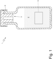
- number 1 denotes as a whole a bottle (small bottle, flask, vial, carpule, syringe or container of various formats) for example, a single-use one (i.e. disposable which is therefore used only once and is then replaced) of a type known to contain a product 2 of the pharmaceutical industry (typically liquid or powder).
- the bottle 1 is closed by means of a cap 3, possibly covered with a plastic coating 4 which must be removed in order to remove the cap 3, and is provided with (at least) one label 5 which is glued to an external surface of the bottle 1.
- number 6 denotes as a whole a washing machine designed for cleaning (washing, blowing) each bottle 1 before said bottle 1 is filled with a given quantity of product 2 in a filling station of a filling machine for bottles 1.
- the bottles 1 are moved along a processing path by means of a succession of conveyors described in the following.
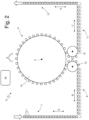
- the washing machine 6 illustrated in Figure 2 comprises an input conveyor 7 which is designed to move a succession of bottles 1 along a linear segment A of the processing path towards a screw transporter 8, which is arranged upstream of a cleaning unit 9 and is designed to move the succession of bottles 1 along a further linear segment B of the processing path, substantially perpendicular to the segment A, towards the cleaning unit 9, passing through a star-like feeding conveyor 10 interposed between the screw transporter 8 and cleaning unit 9.
- the cleaning unit 9 in turn comprises a cleaning conveyor 14 which moves the bottles 1 along a further circular segment E of the processing path, along which each bottle 1 is subjected to a cleaning cycle.
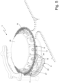
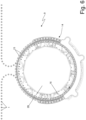
- the cleaning conveyor 14 illustrated in Figures from 5 to 9 is a rotary conveyor which rotates around a vertical rotation axis Z and which carries in a cantilevered manner a plurality of gripping devices 15 (typically pliers or forks).
- the gripping devices 15 are mounted rotatably on a plurality of reticular beams 16 and can be moved forward by the cleaning conveyor 14 along the segment E of the processing path; in particular, in the embodiment illustrated in the attached Figures, each beam 16 supports an assembly of six gripping devices 15 side by side to one another; consequently, the rotation of each beam 16 determines the simultaneous rotation of all six gripping devices 15 carried by the beam 16.
- Each gripping device 15 is designed to pick-up a bottle 1 at the entering of the cleaning conveyor 14 by grasping it with a gripping section arranged near a dispensing opening of the bottles 1 (typically at the neck of the bottles 1), rotating the bottle 1 by 180° until it is placed with the dispensing opening arranged downwards, and to feed the bottle 1 rotated (i.e. "upside down “ with the bottom facing upwards and with the neck ending in the dispensing opening oriented downwards) through successive cleaning stations and then rotating the bottle 1 again before leading it out of the cleaning unit 9.
- the bottles 1 enter the cleaning conveyor 14 oriented upwards (i.e. with the dispensing opening facing upwards), are overturned (i.e. arranged with the dispensing opening facing downwards) by means of a 180° rotation and are finally overturned again (i.e. arranged again with the dispensing opening facing upwards) before exiting the cleaning conveyor 14.
- the cleaning unit 9 illustrated in Figures from 5 to 9 comprises, furthermore, a plurality of dispensing ducts 17 carried by a circular support 18 which is arranged in a fixed position (i.e. it does not rotate), is coaxial to the rotation axis Z of the cleaning conveyor 15 and is arranged below the cleaning conveyor 15.
- the circular support 18 carries in a cantilever manner a plurality of shelves 19 (which, in the illustrated embodiment, are integral one with the other as they are made in a single body) on which the dispensing ducts 17 are arranged, each of which is designed for dispensing an operating fluid (not illustrated) inside a bottle 1, when the bottle 1 is with the dispensing opening oriented downwards above the corresponding dispensing duct 17.
- the cleaning unit 9 comprises, furthermore, a plurality of feeding collectors 20a, 20b, 20c, in the present case three feeding collectors 20a, 20b, 20c, each designed for feeding a different operating fluid (which can be demineralized, purified, recycled water, water added with silicone, water added with sterilizing agents, dry air, or ionized air, depending on the operations that the operating fluid must carry out) and each connectable to at least one dispensing duct 17.
- a different operating fluid which can be demineralized, purified, recycled water, water added with silicone, water added with sterilizing agents, dry air, or ionized air, depending on the operations that the operating fluid must carry out
- the dispensing ducts 17 are assembled in a plurality of dispensing assemblies 21 which are independent of and separate from one another and are arranged in succession one after the other along the processing path.
- Each dispensing assembly 21 is formed by four dispensing ducts 17 and is provided with a single distributing device 22 connectable to each of the feeding collectors 20a, 20b, 20c to receive an operating fluid and distribute the same to the dispensing ducts 17 of the dispensing assembly 21 (in the present case to the four dispensing ducts 17 of each dispensing assembly 21); in other words, each dispensing assembly 21 is potentially connectable to all the feeding collectors 20a, 20b, 20c and is effectively connected to a single feeding collector 20a or 20b or 20c at a time.
- each feeding collector 20a, 20b, 20c has a plurality of outputs 23 which can be used by a distributing device 22 (i.e. connected to a distributing device 22), or unused (i.e. disconnected from all distributing devices 22 and therefore from all the dispensing assemblies 21) and typically closed by means of a respective screwed cap (not illustrated) and/or by means of a valve which is integrated with the feeding collector 20a or 20b or 20c and can be manually or electrically operated.
- connection between the outputs 23 of the feeding collectors 20a, 20b, 20c and the distributing devices 22 of the various dispensing assemblies 21 takes place by means of a plurality of flexible pipes 24, each arranged to connect a single output 23 of a feeding collector 20a or 20b or 20c to an input 25 of a distributing device 22 of a single dispensing assembly 21, independently of the remaining dispensing assemblies 21, so that by adding a new pipe 24, or by moving an existing pipe 24, it is possible to selectively connect the inputs 25 of the various distributing devices 22 to respective feeding collectors 20.
- the dispensing ducts 17 of each dispensing assembly 21 are mounted on the corresponding distributing device 22, so as to be oriented with the dispensing opening facing upwards (i.e. so as to dispense the operating fluid upwards) and comprise threaded pipes 26 that protrude from the distributing device 22 and on which the corresponding dispensing ducts 17 are screwed, provided with respective dispensing nozzles 27.
- the circular support 18 which carries the shelves 19 and therefore the various cleaning assemblies 21 is movable close to or away from the cleaning conveyor 14 in a vertical direction (parallel to the rotation axis Z of the cleaning conveyor 14) under the action of an actuating device (schematically illustrated in Figure 7 ) between an operating position, in which each dispensing duct 17 is partially arranged inside a corresponding bottle 1 carried with the dispensing opening facing downwards by a gripping device 15, and a transport position in which each dispensing duct 17 is completely on the outside relative to the bottles 1 carried by the cleaning conveyor 14 so as not to hinder the bottles 1 during their movement from one cleaning station to the next (i.e. from a dispensing assembly 21 which dispenses a given operating fluid to another dispensing assembly 21, which dispenses an operating fluid that can be different from the previous one).
- each bottle 1 is moved by the cleaning conveyor 14 with the dispensing opening oriented downwards and is stopped, by the cleaning conveyor 14, at a cleaning station and above a dispensing duct 17 of a dispensing assembly 21 arranged in a lowered or rest position in which the dispensing duct 17 is spaced from the bottle 1 so as not to hinder the movement of the bottle 1.
- the circular support 18, under the action of the actuating device is lifted from the transport position or lowered position towards an operating or raised position in which the upper (terminal) part of each dispensing duct 17, provided with the dispensing nozzle 27, is inside the bottle 1.
- each feeding collector 20a, 20b, 20c dispenses, preferably by means of a dispensing pump (not illustrated), the operating fluid through the pipes 24 to each distributing device 22 connected to one of the outputs 23 of the feeding collector 20a, 20b, 20c, which distributing device 22 will distribute the operating fluid to the various dispensing ducts 17 of each dispensing assembly 21 to let the operating fluid out (spray) from the dispensing nozzles 27 directly into the respective bottles 1 for a time sufficient to complete the cleaning step.
- the dispensing assemblies 21 are lowered to make each dispensing duct 17 exit from the corresponding bottle 1 and are placed again in the transport or rest position.
- both the bottles 1 and the dispensing ducts 17 are moving along the processing path: the bottles 1 are carried by the gripping devices 15 (which are in turn carried by the cleaning conveyor 14) while the dispensing ducts 17 are set into rotation by the shelves 19 which rotate coaxial to the rotation axis Z of the cleaning conveyor 14.
- the dispensing ducts 17 are in the operating position inside the bottles 1 and rotate in the same direction with the cleaning conveyor 14. Once the cleaning step is over, the dispensing ducts 17 are brought to the rest position and rotate in a direction different from the rotation direction of the cleaning conveyor 14. Therefore, this alternating movement of the dispensing ducts 17 allows to perform the internal cleaning cycle without stopping the bottles 1.
- the bottles 1 could be moved forward step by step corresponding to the various cleaning stations; in this case, each bottle 1 which has just been treated is then moved towards a new cleaning station (i.e. towards another dispensing assembly 21 which dispenses a given operating fluid that may be different from the previous one) until the cleaning cycle is completed (i.e. until each bottle 1 has been moved in the area of a dispensing duct 17 of each active dispensing assembly 21).
- the latter and the dispensing ducts 17 are moved mutually in order for the dispensing nozzles 27 of the dispensing ducts 17 to be inside the respective bottles 1 during the various cleaning steps so that the operating fluid directly and optimally contacts the inner walls of the bottles 1.
- the operating fluid is let out of the dispensing duct 17 during a single dispensing operation without interruption (i.e. during the single dispensing operation the flow of the operating fluid is never interrupted).
- the operating fluid is let out of the dispensing duct 17 during two (or more) successive dispensing operations between which a pause is provided (i.e. a lack of dispensing of the operating fluid).
- the movement at step of the cleaning conveyor 14 during its rotation around the axis Z is such as to make sure that a number of bottles 1 equal to the number of dispensing ducts 17 which form each dispensing assembly 21 is moved at each feeding step (i.e. at each rotation step around the rotation axis Z) from a cleaning station to the next cleaning station, therefore from a position in the area of a dispensing assembly 21 to the next dispensing assembly 21.
- the cleaning unit 9 comprises eleven dispensing assemblies 21, each comprising four dispensing ducts 17; whereby each bottle 1 during a cleaning cycle undergoes a maximum of eleven cleaning steps, which can be different from one another, since each of these dispensing assemblies 21 can be selectively and independently connected to any of the various feeding collectors 20a, 20b, 20c.
- the cleaning unit 9 comprises three different feeding collectors 20a, 20b and 20c which are arranged inside the circular support 18; each feeding collector 20a, 20b or 20c has twelve outputs 23 in order to be connectable to all eleven dispensing assemblies 21, i.e. a single feeding collector 20a, 20b or 20c could be connected to all eleven dispensing assemblies 21 (in fact there is a twelfth output 23 which is in excess since there are only eleven dispensing assemblies 21 and which is in reserve).
- Each feeding collector 20a, 20b or 20c is connected to a respective operating fluid feeding system 29a or 29b or 29c, which can for example provide a tank (not illustrated) that contains an operating fluid and which is connected, possibly by means of a pump, to the respective feeding collector 20a or 20b or 20c.
- the operating fluid can be, for example, demineralized water, purified water, recycled water, water added with silicone, dry air, or ionized air.
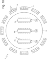
- Figures from 11 to 13 show some of the different configurations that the cleaning unit 9 of the invention can assume, which corresponds to as many different cleaning cycles.
- the feeding collector 20a is connected to the distributing devices 22 of dispensing assemblies 21 arranged in the initial part of the segment E of the processing path and could, for example, feed a cleaning liquid (typically water), the feeding collector 20b, which is connected to distributing devices 22 of dispensing assemblies 21 arranged in the final part of the segment E of the processing path could feed dry (preferably heated) air so as to perform a drying step subsequent to the washing step; while the collector 20c is unused.
- a cleaning liquid typically water
- the feeding collector 20b which is connected to distributing devices 22 of dispensing assemblies 21 arranged in the final part of the segment E of the processing path could feed dry (preferably heated) air so as to perform a drying step subsequent to the washing step; while the collector 20c is unused.
- FIG 13 some of the outputs 23 of the feeding collector 20c are also used: in detail, in Figure 13 the distributing devices 22 of a dispensing assembly 21 arranged in the initial part of the segment E of the processing path is connected to the feeding collector 20b, the distributing devices 22 of three consecutive dispensing assemblies 21 are connected to the feeding collector 20a and the distributing devices 22 of the remaining dispensing assemblies 21 arranged in the final part of the segment E of the processing path are connected in part to the feeding collector 20b and the remaining part to the feeding collector 20c, therefore this configuration could represent, for example, a cleaning cycle which envisages three distinct washing steps followed by a drying step, in the event that the collectors 20a and 20b are designed for feeding fluids cleaning agents, for example water and ionized air, and the collector 20c is designed for feeding dry air (preferably hot).
- the collectors 20a and 20b are designed for feeding fluids cleaning agents, for example water and ionized air
- the collector 20c is designed for feeding dry air (preferably hot).
- the unused dispensing assemblies 21 could be provided with plugs (not illustrate) mounted on the threaded pipe 26 of the distributing device 22 of each of the dispensing ducts 17 of the dispensing assembly 21 so as to prevent unwanted leaks of the operating fluid in the event of connection errors and, at the same time, protect the dispensing ducts 17 and prevent the same from being damaged or blocked during their non-use, for example due to external agents such as dust, production waste, etc.
- valves preferably electric ones, could be provided which can be operated to prevent the flow towards the unused dispensing assemblies 21, said valves could for example be arranged at the entering of each distributing device 22.
- each dispensing assembly 21 could be formed by any number of dispensing ducts 17, in particular as the number of dispensing ducts 17, which forms a single dispensing assembly 21, increases, the number of distributing devices to be connected to the various feeding collectors 20a, 20b, 20c and, consequently, the number of outputs 23 of each feeding collector 20a, 20b, 20c will decrease, thus simplifying the washing unit 9, but at the same time the number of different cleaning steps at which every single bottle 1 along a cleaning cycle can be subjected will decrease.
- the number of dispensing ducts 17, which form each single dispensing assembly 21 decreases, the freedom with which the cleaning cycle can be varied will increase, i.e. the possible cleaning steps to which each individual bottle 1 moving along the cleaning conveyor 14 will increase.
- the cleaning unit 9 can also comprise a collecting tank (not illustrated) which collects the water following cleaning and is arranged in a fixed position below the dispensing assembly 21.
- a suction source (situation not illustrated) can also be provided to suck the ionized air so that it does not disperse into the surrounding environment.
- the feeding conveyor 14 could support any other seat (not illustrated), in place of the gripping devices 15, designed for housing a container 1 and for moving the container 1 suitably oriented along the segment E of the processing path (i.e. along the succession of dispensing ducts 17).
- the cleaning conveyor 14 is mounted on a frame 30 of the washing machine 6 so as to be movable along a vertical adjustment direction, which is preferably coaxial to the rotation axis Z of the cleaning conveyor 14.
- the washing machine 6 comprises adjustment means 31 designed to move the cleaning conveyor 14 along the adjustment direction to change a vertical height of the gripping devices 15 with respect to the feeding conveyor 10, which moves the bottles 1 towards the gripping devices 15.
- the adjustment means 31 are arranged to change a vertical portion of the cleaning conveyor 14 so that the vertical portion of the gripping devices 15 coincides with a vertical portion of the gripping section of the bottles 1 entering the cleaning conveyor 14; as previously said, the gripping section of a bottle 1 is typically arranged near the opening of the bottle 1, preferably at the neck of the bottle 1.
- the bottles 1 enter the cleaning conveyor 14 carried by the feeding conveyor 10 interposed between the screw transporter 8 and the cleaning unit 9; in the embodiment illustrated in the attached Figures, the feeding conveyor 10 is a rotating star-like conveyor, while according to other embodiments not illustrated, the feeding conveyor 10 could be replaced by any other linear or rotating conveyor which moves the bottles 1 in an upright position towards the cleaning conveyor 14.
- the drum 28 of the cleaning conveyor 14 is mounted on a shaft 32 which is rotatable around the rotation axis Z and is also axially slidable along the rotation axis Z so as to allow the lowering or lifting of the cleaning conveyor 14 by suitably operating the adjustment means 31.
- the adjustment means 31 comprise a vertical support rod 33 (in this case a screw) which supports the shaft 32 with the interposition of an oblique ball bearing 34 and is connected to an actuating device 35 designed to actuate the rod 33 in motion along the rotation axis Z.
- a vertical support rod 33 in this case a screw
- actuating device 35 designed to actuate the rod 33 in motion along the rotation axis Z.
- the actuating device 35 comprises a nut 36 internally threaded and coupled to the rod 33 and an electric motor (schematically illustrated in Figure 8 ) designed to rotate the nut 36 so that the rotation of the nut 36 determines the screwing of the rod 33 and consequently a movement of the shaft 32, and therefore of the entire cleaning conveyor 14, along the rotation axis Z.
- Further bearings 37 are also arranged between the shaft 32 and the frame 30 of the washing machine 6 above the oblique ball bearing 34 and are both shaped to allow rotation of the shaft 32 around the rotation axis Z, and to allow the movement of the shaft 32 along the rotation axis Z.
- the adjustment means 31 are preferably connected to a control unit 38 (schematically illustrated in Figure 2 ) configured to determine the format of the bottles 1 entering the washing machine 6 and therefore to change the vertical height of the gripping devices 15 accordingly, so as to ensure that each gripping device 15 grips the gripping section of a corresponding bottle 1.
- the control unit 38 comprises at least one memory unit designed for storing a program associating each format of the containers 1 with a corresponding vertical portion of the gripping devices 15. For this reason, once the data about the format of the containers 1 has been entered, the control unit 38, based on the programming contained in the memory unit, will activate the adjustment means 31 to ensure the correct gripping of the containers 1 by means of the gripping devices 15.
- the format of the containers 1 can be entered manually by the operators before starting to use the washing machine 6 by using a user interface (not illustrated) which is connected to the control unit 38.
- the washing machine 6 can comprise detection means (for example optical sensors) capable of scanning the containers 1 moving along the processing path and sending the corresponding data to the control unit 38, which, by comparing the data with those contained in the memory unit, will be able to identify the format of the containers 1 and consequently, again on the basis of the data contained in the programming, to operate the adjustment means 31.
- actuating device 35 described above and shown in Figures 8 and 9 could be replaced with any other actuating device with the same function.
- the rod 33 could be connected directly to a linear actuating device that can be operated to lift or lower the rod 33 and therefore to change the vertical height of the gripping devices 15.
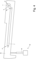
- the washing machine 6 comprises further adjustment means 39 designed to adjust the inclination of the input conveyor 7 relative to the horizontal direction, and therefore the pressure with which the bottles 1 arrive at the screw transporter 8, to ensure that each pitch of the helical ridge of the screw transporter 8 receives a bottle 1 coming from the input conveyor 7, in order to optimize the efficiency of the washing machine 6 in terms of speed and feed regularity of the bottles 1.
- the input conveyor 7 is carried by a support frame 40 which is mounted rotatably around a horizontal rotation axis Y so that, when suitably operated by the adjustment means 39, can rotate around the axis Y consequently changing the inclination of the input conveyor 7 relative to the horizontal direction.
- the adjustment means 39 are arranged to act on the support frame 40 so as to change the vertical height of an input end 41 of the input conveyor 7 and keep the vertical height at an output end 42 of the input conveyor 7 constant, since at the output end 42 the input conveyor 7 is coupled to the screw transporter 8 so that said section cannot be moved in order not to lose contact with the screw transporter 8; in other words, the output end 42 of the input conveyor 7 represents the fixed point around which the support frame 40 and therefore the input conveyor 7 can rotate.
- the adjustment means 39 comprise a linear actuating device 43 (for example a pneumatic or hydraulic cylinder) which is connected to the end of the support frame 40 opposite the screw transporter 8 and is designed to lift or lower said end.
- a linear actuating device 43 for example a pneumatic or hydraulic cylinder
- the rotation axis Y around which the support frame 40 rotates in order to change the inclination of the input conveyor 7 is parallel, and even more preferably coaxial, to the screw transporter 8.
- the control unit 38 of the washing machine 6 is configured to determine a format of the containers 1 entering the washing machine 6 and therefore to change the inclination of the input conveyor 7 relative to the horizontal direction so as to ensure that each pitch of the helical ridge of the screw transporter 8 receives a container 1 coming from the input conveyor 7.
- the control unit 38 comprises at least one memory unit designed for containing a program associating each format of the containers 1 with a corresponding inclination of the input conveyor 7 relative to the horizontal direction. Therefore, once the data about the format of the containers 1 has been entered, the control unit 38, based on the programming contained in the memory unit, will activate the adjustment means 39 to ensure that the containers 1 arrive at the screw transporter 8 with a pressure such as to ensure that each pitch of the helical ridge of the screw transporter 8 is occupied by a container 1.
- the format of the containers 1 can be entered manually by the operators before starting to use the washing machine 6 by using a user interface (not illustrated) which is connected to the control unit 38.
- the washing machine 6 can comprise detection means similar to those already described, which can coincide with those already described, and which are arranged to detect the format of the containers 1 moving along the processing path and sending the corresponding data to the control unit 38 which, by comparing the data with those contained in the memory unit, will be able to identify the format of the container 1 and consequently always on the basis of the format of the containers 1 will actuate the adjustment means 39.
- actuating device 41 could be replaced with any other actuating device having the same function.
- the washing machine 6 described above has numerous advantages.
- the washing machine 6 allows to change the cleaning cycle performed by the washing machine 6 in a simple and quick manner by simply moving the pipes 24 to connect each distributing device 22 to an output 23 of a feeding collector 20a, 20b, 20c and/or by adding new pipes 24 to connect previously disconnected distributing devices 22. Therefore, the washing machine 6 thus obtained is extremely flexible and is capable of performing various cleaning cycles, without having to make a special washing machine 6 for each possible cleaning cycle.
- a washing machine 6 thus made allows the possibility to change the cleaning cycle even during the useful life of the washing machine 6 itself, simply by changing the various connections between the outputs 23 of each feeding collector 20a, 20b, 20c and the distributing devices 22, by moving and/or adding pipes 24.
- the washing machine 6 described above due to the presence of the adjustment means 31 designed to change the vertical height of the cleaning conveyor 14 and therefore of the gripping devices 15 depending on the format of the containers 1, ensures that each container 1 is grasped by a corresponding gripping device 15 in a correct manner (i.e. at the gripping section).
- the washing machine 6 thus made can be adapted in a simple a quick manner to containers 1 of any format, by adjusting the vertical height of the cleaning conveyor 14 according to the vertical height of the gripping section of the containers 1 entering the washing machine 6.
- the washing machine 6, due to the presence of the adjustment means 39 designed to adjust the inclination of the input conveyor 7, ensures that each pitch of the helical ridge of the screw transporter 8 receives a container 1 coming from the input conveyor 7, improving in this way the performance of the washing machine 6 in terms of feed speed, and therefore of the productivity of the washing machine 6.
- washing machine 6 described above is simple and inexpensive to implement, since compared to a similar known washing machine 6 it only requires the addition of adjustment means 31 and/or 39 and a different assembling of the dispensing ducts 17.
Landscapes
- Engineering & Computer Science (AREA)
- Mechanical Engineering (AREA)
- Cleaning In General (AREA)
- Detail Structures Of Washing Machines And Dryers (AREA)
- Detergent Compositions (AREA)
- Filling Of Jars Or Cans And Processes For Cleaning And Sealing Jars (AREA)
Description
- This patent application claims priority from
Italian patent application no. 102019000007845 filed on 03/06/2019 - The present invention relates to a washing machine for containers, i.e. bottles, small bottles, flasks, vials, carpules etc. of various formats, in particular for products of the pharmaceutical industry.
- The present invention finds advantageous application in the cleaning of bottles for products of the pharmaceutical industry, to which the following disclosure will make explicit reference without thereby losing its generality.
- In the industry of bottle filling machines for products of the pharmaceutical industry it is known to have a washing machine for bottles upstream of the filling station of a bottle filling machine to clean each container before filling it with a given quantity of product of the pharmaceutical industry, in liquid or powder form.
- A known washing machine for containers for products of the pharmaceutical industry comprises: a linear input conveyor for moving a plurality of bottles along a segment of a processing path; a screw transporter arranged immediately downstream of the linear feeding conveyor to receive the bottles coming from the linear input conveyor and to move the bottles along another segment of the processing path; a cleaning unit arranged downstream of the screw transporter and designed for cleaning the bottles while moving along a cleaning conveyor carried by the cleaning unit; a further screw transporter arranged downstream of the cleaning unit to receive the cleaned bottles leaving the cleaning unit and to move the bottles towards an output conveyor, through which the cleaned bottles will be directed towards a further station of the bottle filling machine, typically towards the weighing station or towards the filling station. A known washing machine comprises, furthermore, a feeding conveyor arranged immediately upstream of the cleaning unit to feed the bottles towards the cleaning unit and a pick-up conveyor arranged at the exit of the cleaning unit to receive the bottles leaving the cleaning unit.
- The cleaning conveyor carries in a cantilevered manner a plurality of gripping devices (typically pliers or forks), which are designed to take the bottles, by grasping them at the neck, rotate them so that the dispensing opening of each bottle is oriented towards the bottom, move them rotated (i.e. "upside down" with the bottom facing up and with the neck ending in the dispensing opening oriented downwards) along a plurality of cleaning stations, and then rotate them again (i.e. bring them back with the bottom facing down and with the neck ending in the dispensing opening oriented upwards) before conveying them out of the cleaning unit.
- A known cleaning unit comprises, furthermore, a plurality of vertically oriented dispensing ducts which are connected to a system for feeding an operating fluid (which can be, for example, demineralized water, purified water, recycled water, water added with silicone, dry air, ionized air) and ending with a dispensing nozzle from which the more or less pressurized operating fluid flows, when necessary. Through a cleaning unit thus made, each bottle is moved by the gripping devices with the dispensing opening oriented downwards, and is stopped above a dispensing duct arranged in a transport position or in a rest position (in which the dispensing duct is spaced from the bottle so as not to hinder the movement of the bottle along the cleaning conveyor). Once the bottle has been stopped over the dispensing duct, the dispensing duct is lifted from the transport or rest position to a raised position or working position, wherein the top (end) of the dispensing duct provided with the dispensing nozzle is arranged inside the bottle. At this point, the feeding system pumps an operating fluid under pressure (which can be, for example, demineralized water, purified water, recycled water, water added with silicone, dry air, ionized air) towards the dispensing duct so as to let out (spray) the operating fluid from the dispensing nozzle directly into the bottle for sufficient time to complete the cleaning step. At the end of the cleaning step, the dispensing duct is lowered to exit the bottle and place itself again in the transport or rest position, the freshly treated bottle is then moved towards the exit of the cleaning unit or towards another dispensing duct to start a new step of the cleaning cycle.
- In particular, during a cleaning cycle each bottle, moving along the cleaning conveyor, is subjected to the action of several operating fluids, the various dispensing ducts are, in fact, typically arranged to dispense at least two different operating fluids, for example a cleaning liquid (typically water, possibly demineralized, and/or purified and/or recycled and/or water added with silicone) to wash the bottles, and dry air (typically heated) to dry the bottles. The feeding system suited to feed the dispensing ducts comprises, in fact, a plurality of feeding collectors, each dedicated to feed a particular operating fluid, and each connected to one or more dispensing ducts to introduce the operating fluid into the dispensing duct.
- The washing machine described above has some drawbacks.
- In the first place, a washing machine thus made allows only one cleaning cycle to be carried out, which is repeated and is always the same since the various dispensing ducts are each connected to a particular feeding collector. Therefore if, for any reason (e.g. when the customer and/or the material with which the bottles are made and/or the type of product to be inserted inside is changed) the cleaning cycle of the bottles needs to be changed (i.e. the sequence with which the different operating fluids acting upon each bottle needs to be changed), it is necessary to use a different washing machine, in which the dispensing ducts that follow one another along the cleaning conveyor (and therefore along which each bottle is moved in succession) are connected to the feeding collectors of the feeding system in order to carry out the desired cleaning cycle.
- Another problem encountered with the washing machine described above is linked to the fact that the gripping devices carried by the cleaning conveyor are designed to take the bottles by grasping them from a precise gripping section generally arranged near a dispensing opening of the bottle (typically at the neck of the bottle). In fact, considering that each bottle arrives at a corresponding gripping device moving on the input conveyor (i.e. resting in an upright position on the input conveyor) as the size of the bottle changes, the vertical height of the gripping section will also change, so it will be necessary to consequently change the vertical height of the gripping device to ensure the correct gripping of the bottle. Therefore, to date, as the format of the containers entering the washing machine changes, it is necessary to adjust the position of the gripping devices and/or replace the gripping devices and/or replace, or at least adjust, the connecting means with which the gripping devices are bound to the cleaning conveyor. Said operations are very laborious, require skilled workers and cannot be performed while the washing machine is mounted, therefore they require machine downtime (at least for the time necessary to complete the aforementioned replacement and/or adjustment operations) with obvious disadvantages in terms of costs and production time.
- A further problem of known washing machines such as the one proposed is linked to the fact that in order for the washing machine to work at its best, i.e. at maximum efficiency, it is necessary that each pitch of the helical ridge of the screw transporter receives a bottle; however, as the format (i.e. shape and size) of the bottles varies, the amount of thrust with which the bottles arrive at the screw transporter varies, so that for given bottle formats a not optimal loading of the screw transporter could occur (i.e. some pitches of the helical ridge of the screw transporter could remain unused). To try to remedy this problem, some washing machines are designed to change the movement speed of the input conveyor arranged upstream of the screw transporter as the size of the bottles entering the washing machine changes. However, the increase in the forward speed of the input conveyor arranged upstream of the screw transporter also determines a considerable slipping of the bottles on the input conveyor. The slipping of the bottles on the input conveyor causes an increase in the wear of the feeding conveyor with a consequent reduction in the useful life of the feeding conveyor and also could cause an irregular movement of the bottles, which in the worst case would make the solution ineffective.
- Patent application
EP0734998A1 describes a conveyor which moves the bottles in a bottle treatment machine; in particular, the conveyor has a transport surface adjustable in height according to the size of the bottles. - The object of the present invention is to provide a washing machine for products of the pharmaceutical industry, which washing machine is free from at least part of the above-mentioned drawbacks and is, at the same time, easy and inexpensive to manufacture.
- According to the present invention, a washing machine for containers is provided, in particular for products of the pharmaceutical industry, according to what is claimed in the attached claims.
- The claims describe embodiments of the present invention forming an integral part of the present description.
- The present invention will now be described with reference to the attached drawings, which illustrate some non-limiting examples of embodiments, wherein:
-
Figure 1 is a schematic view of a bottle for products of the pharmaceutical industry; -
Figure 2 is a plan and schematic view of a bottle washing machine of the type illustrated inFigure 1 ; -
Figures 3 and4 are side views, schematic and on an enlarged scale of a feeding conveyor and of a screw transporter of the washing machine ofFigure 2 in a first and a second operating configuration, respectively; -
Figure 5 is a schematic perspective view with parts removed for clarity of a cleaning conveyor of the washing machine ofFigure 2 ; -
Figure 6 is a plan view of the cleaning conveyor ofFigure 5 ; -
Figure 7 is a schematic and enlarged view of a part of the cleaning conveyor ofFigure 5 ; -
Figure 8 is a schematic and vertical section view of the cleaning conveyor ofFigure 5 ; -
Figure 9 is an enlarged view of a part of the vertical section ofFigure 8 ; and -
Figures 10 to 13 are schematic plan views of the cleaning conveyor ofFigure 5 and of a corresponding feeding system for operating fluids in a non-operating configuration and in three different operating configurations, respectively. - In
Figure 1 , number 1 denotes as a whole a bottle (small bottle, flask, vial, carpule, syringe or container of various formats) for example, a single-use one (i.e. disposable which is therefore used only once and is then replaced) of a type known to contain a product 2 of the pharmaceutical industry (typically liquid or powder). The bottle 1 is closed by means of a cap 3, possibly covered with a plastic coating 4 which must be removed in order to remove the cap 3, and is provided with (at least) one label 5 which is glued to an external surface of the bottle 1. - In
Figure 2 ,number 6 denotes as a whole a washing machine designed for cleaning (washing, blowing) each bottle 1 before said bottle 1 is filled with a given quantity of product 2 in a filling station of a filling machine for bottles 1. In particular, inside thewashing machine 6 the bottles 1 are moved along a processing path by means of a succession of conveyors described in the following. - The
washing machine 6 illustrated inFigure 2 comprises aninput conveyor 7 which is designed to move a succession of bottles 1 along a linear segment A of the processing path towards ascrew transporter 8, which is arranged upstream of acleaning unit 9 and is designed to move the succession of bottles 1 along a further linear segment B of the processing path, substantially perpendicular to the segment A, towards thecleaning unit 9, passing through a star-like feeding conveyor 10 interposed between thescrew transporter 8 andcleaning unit 9. Thewashing machine 6 comprises, furthermore, ascrew transporter 11 designed to receive the clean bottles 1 which, from thecleaning unit 9, are conveyed outwards by means of a star-like pick-up conveyor 12 arranged immediately downstream of thecleaning unit 9 for guiding the bottles 1 from thecleaning unit 9 towards thescrew transporter 11, which is designed to move the bottles 1 along a further linear segment C of the processing path which ends at anoutput conveyor 13, through which the bottles 1 moving along the linear segment D of the processing path, substantially perpendicular to the segment C, exiting thewashing machine 6. Theinput conveyor 7 and theoutput conveyor 13 can either be linear or rotary and in the attached Figures are linear conveyors. - The
cleaning unit 9 in turn comprises acleaning conveyor 14 which moves the bottles 1 along a further circular segment E of the processing path, along which each bottle 1 is subjected to a cleaning cycle. - The
cleaning conveyor 14 illustrated in Figures from 5 to 9 is a rotary conveyor which rotates around a vertical rotation axis Z and which carries in a cantilevered manner a plurality of gripping devices 15 (typically pliers or forks). In detail, thegripping devices 15 are mounted rotatably on a plurality ofreticular beams 16 and can be moved forward by thecleaning conveyor 14 along the segment E of the processing path; in particular, in the embodiment illustrated in the attached Figures, eachbeam 16 supports an assembly of sixgripping devices 15 side by side to one another; consequently, the rotation of eachbeam 16 determines the simultaneous rotation of all sixgripping devices 15 carried by thebeam 16. Eachgripping device 15 is designed to pick-up a bottle 1 at the entering of thecleaning conveyor 14 by grasping it with a gripping section arranged near a dispensing opening of the bottles 1 (typically at the neck of the bottles 1), rotating the bottle 1 by 180° until it is placed with the dispensing opening arranged downwards, and to feed the bottle 1 rotated (i.e. "upside down" with the bottom facing upwards and with the neck ending in the dispensing opening oriented downwards) through successive cleaning stations and then rotating the bottle 1 again before leading it out of thecleaning unit 9. In other words, the bottles 1 enter thecleaning conveyor 14 oriented upwards (i.e. with the dispensing opening facing upwards), are overturned (i.e. arranged with the dispensing opening facing downwards) by means of a 180° rotation and are finally overturned again (i.e. arranged again with the dispensing opening facing upwards) before exiting thecleaning conveyor 14. - The
cleaning unit 9 illustrated in Figures from 5 to 9 comprises, furthermore, a plurality of dispensingducts 17 carried by acircular support 18 which is arranged in a fixed position (i.e. it does not rotate), is coaxial to the rotation axis Z of thecleaning conveyor 15 and is arranged below thecleaning conveyor 15. Thecircular support 18 carries in a cantilever manner a plurality of shelves 19 (which, in the illustrated embodiment, are integral one with the other as they are made in a single body) on which the dispensingducts 17 are arranged, each of which is designed for dispensing an operating fluid (not illustrated) inside a bottle 1, when the bottle 1 is with the dispensing opening oriented downwards above thecorresponding dispensing duct 17. - As illustrated in Figures from 10 to 13, the
cleaning unit 9 comprises, furthermore, a plurality offeeding collectors feeding collectors duct 17. - According to a preferred embodiment of the present invention, the dispensing
ducts 17 are assembled in a plurality of dispensingassemblies 21 which are independent of and separate from one another and are arranged in succession one after the other along the processing path. Eachdispensing assembly 21 is formed by four dispensingducts 17 and is provided with a single distributingdevice 22 connectable to each of thefeeding collectors dispensing ducts 17 of the dispensing assembly 21 (in the present case to the fourdispensing ducts 17 of each dispensing assembly 21); in other words, eachdispensing assembly 21 is potentially connectable to all thefeeding collectors single feeding collector - Furthermore, each
feeding collector outputs 23 which can be used by a distributing device 22 (i.e. connected to a distributing device 22), or unused (i.e. disconnected from all distributingdevices 22 and therefore from all the dispensing assemblies 21) and typically closed by means of a respective screwed cap (not illustrated) and/or by means of a valve which is integrated with thefeeding collector - In particular, the connection between the
outputs 23 of thefeeding collectors distributing devices 22 of thevarious dispensing assemblies 21 takes place by means of a plurality offlexible pipes 24, each arranged to connect asingle output 23 of afeeding collector input 25 of a distributingdevice 22 of asingle dispensing assembly 21, independently of the remainingdispensing assemblies 21, so that by adding anew pipe 24, or by moving anexisting pipe 24, it is possible to selectively connect theinputs 25 of the variousdistributing devices 22 to respective feeding collectors 20. In this way, by connecting at will theinputs 25 of the various distributingdevices 22 with theoutputs 23 of thevarious collectors conveyor 14 through the various dispensing assemblies 21 (i.e. through at least one dispensingduct 17 of each of the dispensing assemblies 21). An example of the extreme flexibility of the system is illustrated inFigures 11 ,12 and13 , from comparison thereof it is evident that simply by changing the configuration (i.e. the number and/or the arrangement) of thepipes 24 it is possible to modify the number and arrangement of thedispensing assemblies 21, which feed a given operating fluid thus changing the cleaning cycle to which each bottle 1 is subjected. For example, supposing to dispense water to thefeeding collector 20a and dry air to thefeeding collector 20b, in the embodiment illustrated inFigure 11 sixconsecutive dispensing assemblies 21 are provided, which dispense water followed by four dispensing assemblies 21 (not all consecutive) that dispense dry air, while the embodiment illustrated inFigure 12 fiveconsecutive dispensing assemblies 21 are provided, which dispense water followed by twoconsecutive dispensing assemblies 21 which dispense dry air. On the other hand, supposing to feed water added with sterilizing additives to thefeeding collector 20a, pure water to thefeeding collector 20b and dry air to thefeeding collector 20c, in the embodiment illustrated inFigure 13 onesingle dispensing assembly 21 is provided, which dispense pure water, followed by threeconsecutive dispensing assemblies 21 which dispense water added with sterilizing additives, followed by twoconsecutive dispensing assemblies 21 which dispense pure water, and finally followed by fiveconsecutive dispensing assemblies 21 which dispense dry air. - With particular reference to
Figure 7 , the dispensingducts 17 of each dispensingassembly 21 are mounted on the corresponding distributingdevice 22, so as to be oriented with the dispensing opening facing upwards (i.e. so as to dispense the operating fluid upwards) and comprise threadedpipes 26 that protrude from the distributingdevice 22 and on which thecorresponding dispensing ducts 17 are screwed, provided withrespective dispensing nozzles 27. - Furthermore, in order to allow the cleaning cycle to be carried out, the
circular support 18 which carries theshelves 19 and therefore thevarious cleaning assemblies 21 is movable close to or away from the cleaningconveyor 14 in a vertical direction (parallel to the rotation axis Z of the cleaning conveyor 14) under the action of an actuating device (schematically illustrated inFigure 7 ) between an operating position, in which each dispensingduct 17 is partially arranged inside a corresponding bottle 1 carried with the dispensing opening facing downwards by agripping device 15, and a transport position in which each dispensingduct 17 is completely on the outside relative to the bottles 1 carried by the cleaningconveyor 14 so as not to hinder the bottles 1 during their movement from one cleaning station to the next (i.e. from a dispensingassembly 21 which dispenses a given operating fluid to another dispensingassembly 21, which dispenses an operating fluid that can be different from the previous one). - In detail, during a cleaning cycle, each bottle 1 is moved by the cleaning
conveyor 14 with the dispensing opening oriented downwards and is stopped, by the cleaningconveyor 14, at a cleaning station and above a dispensingduct 17 of a dispensingassembly 21 arranged in a lowered or rest position in which the dispensingduct 17 is spaced from the bottle 1 so as not to hinder the movement of the bottle 1. Once each bottle 1 is above a dispensingduct 17, thecircular support 18, under the action of the actuating device, is lifted from the transport position or lowered position towards an operating or raised position in which the upper (terminal) part of each dispensingduct 17, provided with the dispensingnozzle 27, is inside the bottle 1. At this point, each feedingcollector pipes 24 to each distributingdevice 22 connected to one of theoutputs 23 of thefeeding collector device 22 will distribute the operating fluid to the various dispensingducts 17 of each dispensingassembly 21 to let the operating fluid out (spray) from the dispensingnozzles 27 directly into the respective bottles 1 for a time sufficient to complete the cleaning step. At the end of each cleaning step the dispensingassemblies 21 are lowered to make each dispensingduct 17 exit from the corresponding bottle 1 and are placed again in the transport or rest position. It should be noted that during the cleaning step both the bottles 1 and the dispensingducts 17 are moving along the processing path: the bottles 1 are carried by the gripping devices 15 (which are in turn carried by the cleaning conveyor 14) while the dispensingducts 17 are set into rotation by theshelves 19 which rotate coaxial to the rotation axis Z of the cleaningconveyor 14. - In detail, during the cleaning step the dispensing
ducts 17 are in the operating position inside the bottles 1 and rotate in the same direction with the cleaningconveyor 14. Once the cleaning step is over, the dispensingducts 17 are brought to the rest position and rotate in a direction different from the rotation direction of the cleaningconveyor 14. Therefore, this alternating movement of the dispensingducts 17 allows to perform the internal cleaning cycle without stopping the bottles 1. - According to an alternative embodiment, the bottles 1 could be moved forward step by step corresponding to the various cleaning stations; in this case, each bottle 1 which has just been treated is then moved towards a new cleaning station (i.e. towards another dispensing
assembly 21 which dispenses a given operating fluid that may be different from the previous one) until the cleaning cycle is completed (i.e. until each bottle 1 has been moved in the area of a dispensingduct 17 of each active dispensing assembly 21). - Basically, for the purpose of cleaning the bottles 1, the latter and the dispensing
ducts 17 are moved mutually in order for the dispensingnozzles 27 of the dispensingducts 17 to be inside the respective bottles 1 during the various cleaning steps so that the operating fluid directly and optimally contacts the inner walls of the bottles 1. - According to a possible embodiment, the operating fluid is let out of the dispensing
duct 17 during a single dispensing operation without interruption (i.e. during the single dispensing operation the flow of the operating fluid is never interrupted). According to a different embodiment, the operating fluid is let out of the dispensingduct 17 during two (or more) successive dispensing operations between which a pause is provided (i.e. a lack of dispensing of the operating fluid). - Preferably, the movement at step of the cleaning
conveyor 14 during its rotation around the axis Z is such as to make sure that a number of bottles 1 equal to the number of dispensingducts 17 which form each dispensingassembly 21 is moved at each feeding step (i.e. at each rotation step around the rotation axis Z) from a cleaning station to the next cleaning station, therefore from a position in the area of a dispensingassembly 21 to the next dispensingassembly 21. - In the embodiment illustrated in the attached Figures, the
cleaning unit 9 comprises elevendispensing assemblies 21, each comprising four dispensingducts 17; whereby each bottle 1 during a cleaning cycle undergoes a maximum of eleven cleaning steps, which can be different from one another, since each of these dispensingassemblies 21 can be selectively and independently connected to any of thevarious feeding collectors - As illustrated in
Figures 10 to 13 , thecleaning unit 9 comprises threedifferent feeding collectors circular support 18; eachfeeding collector outputs 23 in order to be connectable to all elevendispensing assemblies 21, i.e. asingle feeding collector twelfth output 23 which is in excess since there are only elevendispensing assemblies 21 and which is in reserve). Eachfeeding collector fluid feeding system respective feeding collector - As previously mentioned, Figures from 11 to 13 show some of the different configurations that the
cleaning unit 9 of the invention can assume, which corresponds to as many different cleaning cycles. In particular inFigures 11 and12 , thefeeding collector 20a is connected to the distributingdevices 22 of dispensingassemblies 21 arranged in the initial part of the segment E of the processing path and could, for example, feed a cleaning liquid (typically water), thefeeding collector 20b, which is connected to distributingdevices 22 of dispensingassemblies 21 arranged in the final part of the segment E of the processing path could feed dry (preferably heated) air so as to perform a drying step subsequent to the washing step; while thecollector 20c is unused. Whereas, InFigure 13 some of theoutputs 23 of thefeeding collector 20c are also used: in detail, inFigure 13 the distributingdevices 22 of a dispensingassembly 21 arranged in the initial part of the segment E of the processing path is connected to thefeeding collector 20b, the distributingdevices 22 of threeconsecutive dispensing assemblies 21 are connected to thefeeding collector 20a and the distributingdevices 22 of the remainingdispensing assemblies 21 arranged in the final part of the segment E of the processing path are connected in part to thefeeding collector 20b and the remaining part to thefeeding collector 20c, therefore this configuration could represent, for example, a cleaning cycle which envisages three distinct washing steps followed by a drying step, in the event that thecollectors collector 20c is designed for feeding dry air (preferably hot). - According to an embodiment not illustrated, the
unused dispensing assemblies 21 could be provided with plugs (not illustrate) mounted on the threadedpipe 26 of the distributingdevice 22 of each of the dispensingducts 17 of the dispensingassembly 21 so as to prevent unwanted leaks of the operating fluid in the event of connection errors and, at the same time, protect the dispensingducts 17 and prevent the same from being damaged or blocked during their non-use, for example due to external agents such as dust, production waste, etc. - Alternatively, or in combination, valves, preferably electric ones, could be provided which can be operated to prevent the flow towards the
unused dispensing assemblies 21, said valves could for example be arranged at the entering of each distributingdevice 22. - It is understood that as the number of feeding
collectors washing machine 6 simply by arranging in a different way thepipes 24 and thus modifying the connections between the distributingdevices 22 and theoutputs 23 of thevarious feeding collectors - It is also understood that each dispensing
assembly 21 could be formed by any number of dispensingducts 17, in particular as the number of dispensingducts 17, which forms asingle dispensing assembly 21, increases, the number of distributing devices to be connected to thevarious feeding collectors outputs 23 of eachfeeding collector washing unit 9, but at the same time the number of different cleaning steps at which every single bottle 1 along a cleaning cycle can be subjected will decrease. On the contrary, as the number of dispensingducts 17, which form each single dispensingassembly 21, decreases, the freedom with which the cleaning cycle can be varied will increase, i.e. the possible cleaning steps to which each individual bottle 1 moving along the cleaningconveyor 14 will increase. - The
cleaning unit 9 can also comprise a collecting tank (not illustrated) which collects the water following cleaning and is arranged in a fixed position below the dispensingassembly 21. - In the event that one of the feeding
collectors - It is understood that the feeding
conveyor 14 could support any other seat (not illustrated), in place of thegripping devices 15, designed for housing a container 1 and for moving the container 1 suitably oriented along the segment E of the processing path (i.e. along the succession of dispensing ducts 17). - According to a preferred embodiment of the present invention illustrated in
Figures 8 and9 , the cleaningconveyor 14 is mounted on aframe 30 of thewashing machine 6 so as to be movable along a vertical adjustment direction, which is preferably coaxial to the rotation axis Z of the cleaningconveyor 14. - In said regard, the
washing machine 6 comprises adjustment means 31 designed to move the cleaningconveyor 14 along the adjustment direction to change a vertical height of thegripping devices 15 with respect to the feedingconveyor 10, which moves the bottles 1 towards the grippingdevices 15. In particular, the adjustment means 31 are arranged to change a vertical portion of the cleaningconveyor 14 so that the vertical portion of thegripping devices 15 coincides with a vertical portion of the gripping section of the bottles 1 entering the cleaningconveyor 14; as previously said, the gripping section of a bottle 1 is typically arranged near the opening of the bottle 1, preferably at the neck of the bottle 1. In this way it will be possible, by suitably operating the adjustment means 31, to lift or lower the cleaningconveyor 14 according to the size of the bottles 1 entering thewashing machine 6 so as to make sure that eachgripping device 15 grasps the gripping section of a corresponding bottle 1 while said bottle 1 moves along the feedingconveyor 10 arranged upstream of the cleaningconveyor 14. - According to what is illustrated in
Figures 2 and8 , the bottles 1 enter the cleaningconveyor 14 carried by the feedingconveyor 10 interposed between thescrew transporter 8 and thecleaning unit 9; in the embodiment illustrated in the attached Figures, the feedingconveyor 10 is a rotating star-like conveyor, while according to other embodiments not illustrated, the feedingconveyor 10 could be replaced by any other linear or rotating conveyor which moves the bottles 1 in an upright position towards the cleaningconveyor 14. - In
Figures 8 and9 , thedrum 28 of the cleaningconveyor 14 is mounted on ashaft 32 which is rotatable around the rotation axis Z and is also axially slidable along the rotation axis Z so as to allow the lowering or lifting of the cleaningconveyor 14 by suitably operating the adjustment means 31. - With particular reference to
Figure 9 , the adjustment means 31 comprise a vertical support rod 33 (in this case a screw) which supports theshaft 32 with the interposition of anoblique ball bearing 34 and is connected to anactuating device 35 designed to actuate therod 33 in motion along the rotation axis Z. - According to the embodiment illustrated in
Figures 8 and9 , theactuating device 35 comprises anut 36 internally threaded and coupled to therod 33 and an electric motor (schematically illustrated inFigure 8 ) designed to rotate thenut 36 so that the rotation of thenut 36 determines the screwing of therod 33 and consequently a movement of theshaft 32, and therefore of theentire cleaning conveyor 14, along the rotation axis Z. -
Further bearings 37 are also arranged between theshaft 32 and theframe 30 of thewashing machine 6 above theoblique ball bearing 34 and are both shaped to allow rotation of theshaft 32 around the rotation axis Z, and to allow the movement of theshaft 32 along the rotation axis Z. - The adjustment means 31 are preferably connected to a control unit 38 (schematically illustrated in
Figure 2 ) configured to determine the format of the bottles 1 entering thewashing machine 6 and therefore to change the vertical height of thegripping devices 15 accordingly, so as to ensure that eachgripping device 15 grips the gripping section of a corresponding bottle 1. For this purpose, thecontrol unit 38 comprises at least one memory unit designed for storing a program associating each format of the containers 1 with a corresponding vertical portion of thegripping devices 15. For this reason, once the data about the format of the containers 1 has been entered, thecontrol unit 38, based on the programming contained in the memory unit, will activate the adjustment means 31 to ensure the correct gripping of the containers 1 by means of thegripping devices 15. - In particular, the format of the containers 1 can be entered manually by the operators before starting to use the
washing machine 6 by using a user interface (not illustrated) which is connected to thecontrol unit 38. As an alternative or in combination with the user interface, thewashing machine 6 can comprise detection means (for example optical sensors) capable of scanning the containers 1 moving along the processing path and sending the corresponding data to thecontrol unit 38, which, by comparing the data with those contained in the memory unit, will be able to identify the format of the containers 1 and consequently, again on the basis of the data contained in the programming, to operate the adjustment means 31. - It is understood that the
actuating device 35 described above and shown inFigures 8 and9 could be replaced with any other actuating device with the same function. For example, therod 33 could be connected directly to a linear actuating device that can be operated to lift or lower therod 33 and therefore to change the vertical height of thegripping devices 15. - According to a further preferred embodiment and with reference to
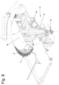
Figures 3 and4 , thewashing machine 6 comprises further adjustment means 39 designed to adjust the inclination of theinput conveyor 7 relative to the horizontal direction, and therefore the pressure with which the bottles 1 arrive at thescrew transporter 8, to ensure that each pitch of the helical ridge of thescrew transporter 8 receives a bottle 1 coming from theinput conveyor 7, in order to optimize the efficiency of thewashing machine 6 in terms of speed and feed regularity of the bottles 1. - According to said embodiment illustrated in
Figures 3 and4 , theinput conveyor 7 is carried by asupport frame 40 which is mounted rotatably around a horizontal rotation axis Y so that, when suitably operated by the adjustment means 39, can rotate around the axis Y consequently changing the inclination of theinput conveyor 7 relative to the horizontal direction. - According to what is illustrated in
Figures 3 and4 , the adjustment means 39 are arranged to act on thesupport frame 40 so as to change the vertical height of aninput end 41 of theinput conveyor 7 and keep the vertical height at anoutput end 42 of theinput conveyor 7 constant, since at theoutput end 42 theinput conveyor 7 is coupled to thescrew transporter 8 so that said section cannot be moved in order not to lose contact with thescrew transporter 8; in other words, theoutput end 42 of theinput conveyor 7 represents the fixed point around which thesupport frame 40 and therefore theinput conveyor 7 can rotate. - According to what is illustrated in
Figures 3 and4 , the adjustment means 39 comprise a linear actuating device 43 (for example a pneumatic or hydraulic cylinder) which is connected to the end of thesupport frame 40 opposite thescrew transporter 8 and is designed to lift or lower said end. - Preferably the rotation axis Y around which the
support frame 40 rotates in order to change the inclination of theinput conveyor 7 is parallel, and even more preferably coaxial, to thescrew transporter 8. - The
control unit 38 of thewashing machine 6 is configured to determine a format of the containers 1 entering thewashing machine 6 and therefore to change the inclination of theinput conveyor 7 relative to the horizontal direction so as to ensure that each pitch of the helical ridge of thescrew transporter 8 receives a container 1 coming from theinput conveyor 7. - The
control unit 38 comprises at least one memory unit designed for containing a program associating each format of the containers 1 with a corresponding inclination of theinput conveyor 7 relative to the horizontal direction. Therefore, once the data about the format of the containers 1 has been entered, thecontrol unit 38, based on the programming contained in the memory unit, will activate the adjustment means 39 to ensure that the containers 1 arrive at thescrew transporter 8 with a pressure such as to ensure that each pitch of the helical ridge of thescrew transporter 8 is occupied by a container 1. - In particular, the format of the containers 1 can be entered manually by the operators before starting to use the
washing machine 6 by using a user interface (not illustrated) which is connected to thecontrol unit 38. Alternatively or in combination with the user interface, thewashing machine 6 can comprise detection means similar to those already described, which can coincide with those already described, and which are arranged to detect the format of the containers 1 moving along the processing path and sending the corresponding data to thecontrol unit 38 which, by comparing the data with those contained in the memory unit, will be able to identify the format of the container 1 and consequently always on the basis of the format of the containers 1 will actuate the adjustment means 39. - It is understood that the
actuating device 41 could be replaced with any other actuating device having the same function. - The embodiments described herein can be combined with one another without departing from the scope of the present invention.
- The
washing machine 6 described above has numerous advantages. - Firstly, due to the subdivision of the dispensing
ducts 17 into separate andindependent dispensing assemblies 21 each provided with its own distributingdevice 22 and each connectable to any of the feedingcollectors washing machine 6 allows to change the cleaning cycle performed by thewashing machine 6 in a simple and quick manner by simply moving thepipes 24 to connect each distributingdevice 22 to anoutput 23 of afeeding collector new pipes 24 to connect previously disconnected distributingdevices 22. Therefore, thewashing machine 6 thus obtained is extremely flexible and is capable of performing various cleaning cycles, without having to make aspecial washing machine 6 for each possible cleaning cycle. Furthermore, awashing machine 6 thus made allows the possibility to change the cleaning cycle even during the useful life of thewashing machine 6 itself, simply by changing the various connections between theoutputs 23 of eachfeeding collector devices 22, by moving and/or addingpipes 24. - Furthermore, the
washing machine 6 described above, due to the presence of the adjustment means 31 designed to change the vertical height of the cleaningconveyor 14 and therefore of thegripping devices 15 depending on the format of the containers 1, ensures that each container 1 is grasped by a correspondinggripping device 15 in a correct manner (i.e. at the gripping section). In other words, thewashing machine 6 thus made can be adapted in a simple a quick manner to containers 1 of any format, by adjusting the vertical height of the cleaningconveyor 14 according to the vertical height of the gripping section of the containers 1 entering thewashing machine 6. - Furthermore, the
washing machine 6, due to the presence of the adjustment means 39 designed to adjust the inclination of theinput conveyor 7, ensures that each pitch of the helical ridge of thescrew transporter 8 receives a container 1 coming from theinput conveyor 7, improving in this way the performance of thewashing machine 6 in terms of feed speed, and therefore of the productivity of thewashing machine 6. - Finally, the
washing machine 6 described above is simple and inexpensive to implement, since compared to a similarknown washing machine 6 it only requires the addition of adjustment means 31 and/or 39 and a different assembling of the dispensingducts 17.
Claims (11)
- A washing machine (6) for containers (1), in particular of the pharmaceutical industry, comprising:an input conveyor (7) designed to move a plurality of containers (1) along a first segment (A) of a processing path;a screw transporter (8), which is designed to move the containers (1) along a second segment (B) of the processing path and is arranged immediately downstream of the input conveyor (7) so as to receive the containers (1) coming directly from the input conveyor (7); anda cleaning unit (9), which is arranged along a third segment (E) of the processing path downstream of the screw transporter (8) and is designed to wash each container (1);wherein:the input conveyor (7) is movable so as to change the inclination of the first segment (A) of the processing path relative to the horizontal direction; andadjustment means (39) are provided, which are designed to adjust the inclination of the first segment (A) of the processing path relative to the horizontal direction;the washing machine is characterized in that the first segment (A) of the processing path defined by the input conveyor (7) is perpendicular to the second segment (B) of the processing path defined by the screw transporter (8).
- The washing machine (6) according to claim 1, wherein:the input conveyor (7) comprises an input end (41) and an output end (42);the screw transporter (8) comprises an input end (44) directly coupled to the output end (42) of the input conveyor (7) and an output end;the adjustment means (39) are suited to keep a vertical height of the output end (42) of the input conveyor (7) constant and to change a vertical height of the input end (41) of the input conveyor (7).
- The washing machine (6) according to claim 1 or 2, wherein the input conveyor (7) comprises a support frame (40), which carries the input conveyor (7) and is hinged so as to rotate around a rotation axis (Y).
- The washing machine (6) according to claim 3, wherein the rotation axis (Y) is parallel to the screw transporter (8).
- The washing machine (6) according to claim 3 or 4, wherein the rotation axis (Y) is parallel and coaxial to the screw transporter (8).
- The washing machine (6) according to any one of the claims from 3 to 5, wherein the adjustment means (39) comprise a linear actuator (43), which is connected to an end of the support frame (40) opposite the screw transporter (8) and is designed to lift or lower said end of the support frame (40).
- The washing machine (6) according to one of the claims from 1 to 6 and comprising a control unit (38) configured to determine a format of the containers (1) and to change the inclination of the first segment (A) of the processing path relative to the horizontal direction depending on the format of the containers (1), so as to ensure that each pitch of the helical ridge of the screw transporter (8) receives one single container (1) coming from the input conveyor (7).
- The washing machine (6) according to claim 7, wherein the control unit (38) comprises a memory designed to contain a program associating each format of the containers (1) with a corresponding inclination of the first segment (A) of the processing path relative to the horizontal direction.
- The washing machine (6) according to claim 7 or 8 and comprising a user interface, which is connected to the control unit (38) so as to manually select the format of the containers (1).
- The washing machine (6) according to claim 7 or 8 and comprising detection means, which are designed to detect the format of the containers (1) entering the washing machine (6), are arranged along the processing path and are connected to the control unit (38).
- A control method to control a washing machine (6) for containers (1), in particular of the pharmaceutical industry, comprising:an input conveyor (7) to move a plurality of containers (1) along a first segment (A) of a processing path;a screw transporter (8), which is designed to move the containers (1) along a second segment (B) of the processing path and is arranged immediately downstream of the input conveyor (7) so as to receive the containers (1) coming directly from the input conveyor (7); anda cleaning unit (9), which is arranged along a third segment (E) of the processing path downstream of the screw transporter (8) and is designed to wash each container;wherein the first segment (A) of the processing path defined by the input conveyor (7) is perpendicular to the second segment (B) of the processing path defined by the screw transporter (8);the control method comprises: the step of detecting the format of the containers (1), and the further step of adjusting the inclination of the first segment (A) of the processing path relative to the horizontal direction depending on the format of the containers (1).
Applications Claiming Priority (1)
| Application Number | Priority Date | Filing Date | Title |
|---|---|---|---|
| IT102019000007845A IT201900007845A1 (en) | 2019-06-03 | 2019-06-03 | Washing machine for containers, in particular for products from the pharmaceutical sector |
Publications (2)
| Publication Number | Publication Date |
|---|---|
| EP3747561A1 EP3747561A1 (en) | 2020-12-09 |
| EP3747561B1 true EP3747561B1 (en) | 2024-12-04 |
Family
ID=68073002
Family Applications (1)
| Application Number | Title | Priority Date | Filing Date |
|---|---|---|---|
| EP20178109.3A Active EP3747561B1 (en) | 2019-06-03 | 2020-06-03 | Washing machine for containers, in particular for products of the pharmaceutical industry |
Country Status (3)
| Country | Link |
|---|---|
| EP (1) | EP3747561B1 (en) |
| IT (1) | IT201900007845A1 (en) |
| PL (1) | PL3747561T3 (en) |
Families Citing this family (3)
| Publication number | Priority date | Publication date | Assignee | Title |
|---|---|---|---|---|
| ES3015514T3 (en) * | 2021-04-06 | 2025-05-06 | Ronchi Mario Spa | Apparatus and method for filling containers arranged in-line with collection of the fluids for washing the supply ducts and the filling heads |
| IT202100012950A1 (en) * | 2021-05-19 | 2022-11-19 | Stevanato Group Spa | MODULAR UNIT FOR WASHING AND DRYING CONTAINERS FOR PHARMACEUTICAL USE AND PRODUCTION LINE OF CONTAINERS FOR PHARMACEUTICAL USE |
| CN117415088B (en) * | 2023-12-15 | 2024-03-22 | 吉林省煜晖生物科技有限公司 | Material inlet cleaning equipment for pharmaceutical container |
Family Cites Families (7)
| Publication number | Priority date | Publication date | Assignee | Title |
|---|---|---|---|---|
| US1756561A (en) * | 1924-03-03 | 1930-04-29 | Creamery Package Mfg Co | Apparatus for filling and capping bottles |
| US3944058A (en) * | 1973-04-19 | 1976-03-16 | Indian Head Inc. | Bottle conveyor system including adjustable height continuous belt conveyor and positive lock spray shielded rotatable bottle carrier |
| ES2126024T3 (en) * | 1993-07-12 | 1999-03-16 | Pepsico Inc | HIGH SPEED BOTTLE WASHING MACHINE AND SPRAY ASSEMBLY FOR NOZZLE. |
| DE29505245U1 (en) * | 1995-03-28 | 1996-04-25 | KHS Maschinen- und Anlagenbau AG, 44143 Dortmund | Conveyors for container handling machines |
| ITTV20120003A1 (en) * | 2012-01-11 | 2013-07-12 | San Benedetto Acqua Minerale | BOTTLE CONVEYOR UNIT FOR BOTTLING SYSTEMS AND ITS FUNCTIONING METHOD |
| DE102016207589A1 (en) * | 2016-05-03 | 2017-11-09 | Krones Ag | Method for feeding and dividing a container stream and container inlet for a processing machine |
| CN108928785A (en) * | 2017-05-25 | 2018-12-04 | 广州隆拓包装机械有限公司 | Bottle discharging and conveying equipment |
-
2019
- 2019-06-03 IT IT102019000007845A patent/IT201900007845A1/en unknown
-
2020
- 2020-06-03 PL PL20178109.3T patent/PL3747561T3/en unknown
- 2020-06-03 EP EP20178109.3A patent/EP3747561B1/en active Active
Also Published As
| Publication number | Publication date |
|---|---|
| IT201900007845A1 (en) | 2020-12-03 |
| EP3747561A1 (en) | 2020-12-09 |
| PL3747561T3 (en) | 2025-03-03 |
Similar Documents
| Publication | Publication Date | Title |
|---|---|---|
| EP3747561B1 (en) | Washing machine for containers, in particular for products of the pharmaceutical industry | |
| KR920010630B1 (en) | Apparatus for shaping and arraying spheroidal bodies of food materials | |
| RU2369556C2 (en) | Device for changing tools set at container treating rotating machines | |
| US20030056466A1 (en) | Solution filling and plugging system to a container | |
| JP2009541021A (en) | Method and container processing machine for processing containers | |
| CN102245318A (en) | Equipment for cleaning containers | |
| US20130081737A1 (en) | Container filling machine | |
| CN101691141B (en) | Aluminum box packing machine | |
| US20120210673A1 (en) | Container Treatment System Having an Aseptic Wall Duct | |
| ITMI20100410A1 (en) | SUPPLY STATION AND FEEDING AND BOTTLE TREATMENT SYSTEM INCLUDING SUCH STATION | |
| US7299606B2 (en) | Method for dispensing fluid substances into containers | |
| JP2022151704A (en) | Bottling line and method for bottling liquid product in bottle aseptically | |
| WO2010073118A1 (en) | Machine for dosing fluids in containers | |
| CN202671181U (en) | Container cleaning device of filling machine | |
| CN102700771B (en) | Stower | |
| US6244423B1 (en) | Methods and apparatus for cleaning rotating belts of item-sorting machines | |
| CN102372243A (en) | Filling device for containers with cleaning system | |
| CN211801895U (en) | Inner container coating device for vacuum cup | |
| CN102428007A (en) | Filling machine with a variable filling rate | |
| US20050138895A1 (en) | Beverage bottling plant for filling bottles with a liquid beverage filling material and a method of operating a beverage bottling plant | |
| EP3771501B1 (en) | An apparatus and a method for washing containers for fluids | |
| EP0486440B1 (en) | Device for dispensing liquid products to rotating elements, especially in bottling machines | |
| JPH0655122B2 (en) | A device that supplies sticks such as cigarettes to processing machines | |
| JP7608375B2 (en) | Method and device for irradiating packages and/or preforms with an electron beam - Patents.com | |
| CN212494430U (en) | High-speed double-channel full-automatic bottle washing machine |
Legal Events
| Date | Code | Title | Description |
|---|---|---|---|
| PUAI | Public reference made under article 153(3) epc to a published international application that has entered the european phase |
Free format text: ORIGINAL CODE: 0009012 |
|
| STAA | Information on the status of an ep patent application or granted ep patent |
Free format text: STATUS: THE APPLICATION HAS BEEN PUBLISHED |
|
| AK | Designated contracting states |
Kind code of ref document: A1 Designated state(s): AL AT BE BG CH CY CZ DE DK EE ES FI FR GB GR HR HU IE IS IT LI LT LU LV MC MK MT NL NO PL PT RO RS SE SI SK SM TR |
|
| AX | Request for extension of the european patent |
Extension state: BA ME |
|
| STAA | Information on the status of an ep patent application or granted ep patent |
Free format text: STATUS: REQUEST FOR EXAMINATION WAS MADE |
|
| 17P | Request for examination filed |
Effective date: 20210527 |
|
| RBV | Designated contracting states (corrected) |
Designated state(s): AL AT BE BG CH CY CZ DE DK EE ES FI FR GB GR HR HU IE IS IT LI LT LU LV MC MK MT NL NO PL PT RO RS SE SI SK SM TR |
|
| STAA | Information on the status of an ep patent application or granted ep patent |
Free format text: STATUS: EXAMINATION IS IN PROGRESS |
|
| 17Q | First examination report despatched |
Effective date: 20230102 |
|
| P01 | Opt-out of the competence of the unified patent court (upc) registered |
Effective date: 20230529 |
|
| GRAP | Despatch of communication of intention to grant a patent |
Free format text: ORIGINAL CODE: EPIDOSNIGR1 |
|
| STAA | Information on the status of an ep patent application or granted ep patent |
Free format text: STATUS: GRANT OF PATENT IS INTENDED |
|
| INTG | Intention to grant announced |
Effective date: 20240702 |
|
| GRAS | Grant fee paid |
Free format text: ORIGINAL CODE: EPIDOSNIGR3 |
|
| GRAA | (expected) grant |
Free format text: ORIGINAL CODE: 0009210 |
|
| STAA | Information on the status of an ep patent application or granted ep patent |
Free format text: STATUS: THE PATENT HAS BEEN GRANTED |
|
| AK | Designated contracting states |
Kind code of ref document: B1 Designated state(s): AL AT BE BG CH CY CZ DE DK EE ES FI FR GB GR HR HU IE IS IT LI LT LU LV MC MK MT NL NO PL PT RO RS SE SI SK SM TR |
|
| REG | Reference to a national code |
Ref country code: CH Ref legal event code: EP |
|
| REG | Reference to a national code |
Ref country code: DE Ref legal event code: R096 Ref document number: 602020042369 Country of ref document: DE |
|
| REG | Reference to a national code |
Ref country code: IE Ref legal event code: FG4D |
|
| REG | Reference to a national code |
Ref country code: LT Ref legal event code: MG9D |
|
| REG | Reference to a national code |
Ref country code: NL Ref legal event code: MP Effective date: 20241204 |
|
| PG25 | Lapsed in a contracting state [announced via postgrant information from national office to epo] |
Ref country code: HR Free format text: LAPSE BECAUSE OF FAILURE TO SUBMIT A TRANSLATION OF THE DESCRIPTION OR TO PAY THE FEE WITHIN THE PRESCRIBED TIME-LIMIT Effective date: 20241204 |
|
| PG25 | Lapsed in a contracting state [announced via postgrant information from national office to epo] |
Ref country code: FI Free format text: LAPSE BECAUSE OF FAILURE TO SUBMIT A TRANSLATION OF THE DESCRIPTION OR TO PAY THE FEE WITHIN THE PRESCRIBED TIME-LIMIT Effective date: 20241204 |
|
| PG25 | Lapsed in a contracting state [announced via postgrant information from national office to epo] |
Ref country code: BG Free format text: LAPSE BECAUSE OF FAILURE TO SUBMIT A TRANSLATION OF THE DESCRIPTION OR TO PAY THE FEE WITHIN THE PRESCRIBED TIME-LIMIT Effective date: 20241204 |
|
| PG25 | Lapsed in a contracting state [announced via postgrant information from national office to epo] |
Ref country code: ES Free format text: LAPSE BECAUSE OF FAILURE TO SUBMIT A TRANSLATION OF THE DESCRIPTION OR TO PAY THE FEE WITHIN THE PRESCRIBED TIME-LIMIT Effective date: 20241204 |
|
| PG25 | Lapsed in a contracting state [announced via postgrant information from national office to epo] |
Ref country code: NO Free format text: LAPSE BECAUSE OF FAILURE TO SUBMIT A TRANSLATION OF THE DESCRIPTION OR TO PAY THE FEE WITHIN THE PRESCRIBED TIME-LIMIT Effective date: 20250304 |
|
| PG25 | Lapsed in a contracting state [announced via postgrant information from national office to epo] |
Ref country code: LV Free format text: LAPSE BECAUSE OF FAILURE TO SUBMIT A TRANSLATION OF THE DESCRIPTION OR TO PAY THE FEE WITHIN THE PRESCRIBED TIME-LIMIT Effective date: 20241204 Ref country code: GR Free format text: LAPSE BECAUSE OF FAILURE TO SUBMIT A TRANSLATION OF THE DESCRIPTION OR TO PAY THE FEE WITHIN THE PRESCRIBED TIME-LIMIT Effective date: 20250305 |
|
| PG25 | Lapsed in a contracting state [announced via postgrant information from national office to epo] |
Ref country code: RS Free format text: LAPSE BECAUSE OF FAILURE TO SUBMIT A TRANSLATION OF THE DESCRIPTION OR TO PAY THE FEE WITHIN THE PRESCRIBED TIME-LIMIT Effective date: 20250304 |
|
| PG25 | Lapsed in a contracting state [announced via postgrant information from national office to epo] |
Ref country code: NL Free format text: LAPSE BECAUSE OF FAILURE TO SUBMIT A TRANSLATION OF THE DESCRIPTION OR TO PAY THE FEE WITHIN THE PRESCRIBED TIME-LIMIT Effective date: 20241204 |
|
| REG | Reference to a national code |
Ref country code: AT Ref legal event code: MK05 Ref document number: 1747610 Country of ref document: AT Kind code of ref document: T Effective date: 20241204 |
|
| REG | Reference to a national code |
Ref country code: DE Ref legal event code: R026 Ref document number: 602020042369 Country of ref document: DE |
|
| PLBI | Opposition filed |
Free format text: ORIGINAL CODE: 0009260 |
|
| PG25 | Lapsed in a contracting state [announced via postgrant information from national office to epo] |
Ref country code: SM Free format text: LAPSE BECAUSE OF FAILURE TO SUBMIT A TRANSLATION OF THE DESCRIPTION OR TO PAY THE FEE WITHIN THE PRESCRIBED TIME-LIMIT Effective date: 20241204 |
|
| PGFP | Annual fee paid to national office [announced via postgrant information from national office to epo] |
Ref country code: PL Payment date: 20250520 Year of fee payment: 6 Ref country code: DE Payment date: 20250627 Year of fee payment: 6 |
|
| PG25 | Lapsed in a contracting state [announced via postgrant information from national office to epo] |
Ref country code: IS Free format text: LAPSE BECAUSE OF FAILURE TO SUBMIT A TRANSLATION OF THE DESCRIPTION OR TO PAY THE FEE WITHIN THE PRESCRIBED TIME-LIMIT Effective date: 20250404 |
|
| PG25 | Lapsed in a contracting state [announced via postgrant information from national office to epo] |
Ref country code: PT Free format text: LAPSE BECAUSE OF FAILURE TO SUBMIT A TRANSLATION OF THE DESCRIPTION OR TO PAY THE FEE WITHIN THE PRESCRIBED TIME-LIMIT Effective date: 20250404 |
|
| PG25 | Lapsed in a contracting state [announced via postgrant information from national office to epo] |
Ref country code: EE Free format text: LAPSE BECAUSE OF FAILURE TO SUBMIT A TRANSLATION OF THE DESCRIPTION OR TO PAY THE FEE WITHIN THE PRESCRIBED TIME-LIMIT Effective date: 20241204 |
|
| 26 | Opposition filed |
Opponent name: FOCKE & CO. (GMBH & CO. KG) Effective date: 20250618 |
|
| PG25 | Lapsed in a contracting state [announced via postgrant information from national office to epo] |
Ref country code: AT Free format text: LAPSE BECAUSE OF FAILURE TO SUBMIT A TRANSLATION OF THE DESCRIPTION OR TO PAY THE FEE WITHIN THE PRESCRIBED TIME-LIMIT Effective date: 20241204 Ref country code: RO Free format text: LAPSE BECAUSE OF FAILURE TO SUBMIT A TRANSLATION OF THE DESCRIPTION OR TO PAY THE FEE WITHIN THE PRESCRIBED TIME-LIMIT Effective date: 20241204 |
|
| PG25 | Lapsed in a contracting state [announced via postgrant information from national office to epo] |
Ref country code: SK Free format text: LAPSE BECAUSE OF FAILURE TO SUBMIT A TRANSLATION OF THE DESCRIPTION OR TO PAY THE FEE WITHIN THE PRESCRIBED TIME-LIMIT Effective date: 20241204 |
|
| PG25 | Lapsed in a contracting state [announced via postgrant information from national office to epo] |
Ref country code: CZ Free format text: LAPSE BECAUSE OF FAILURE TO SUBMIT A TRANSLATION OF THE DESCRIPTION OR TO PAY THE FEE WITHIN THE PRESCRIBED TIME-LIMIT Effective date: 20241204 |
|
| PG25 | Lapsed in a contracting state [announced via postgrant information from national office to epo] |
Ref country code: IT Free format text: LAPSE BECAUSE OF FAILURE TO SUBMIT A TRANSLATION OF THE DESCRIPTION OR TO PAY THE FEE WITHIN THE PRESCRIBED TIME-LIMIT Effective date: 20241204 |
|
| PG25 | Lapsed in a contracting state [announced via postgrant information from national office to epo] |
Ref country code: SE Free format text: LAPSE BECAUSE OF FAILURE TO SUBMIT A TRANSLATION OF THE DESCRIPTION OR TO PAY THE FEE WITHIN THE PRESCRIBED TIME-LIMIT Effective date: 20241204 |
|
| PLAX | Notice of opposition and request to file observation + time limit sent |
Free format text: ORIGINAL CODE: EPIDOSNOBS2 |
|
| PG25 | Lapsed in a contracting state [announced via postgrant information from national office to epo] |
Ref country code: DK Free format text: LAPSE BECAUSE OF FAILURE TO SUBMIT A TRANSLATION OF THE DESCRIPTION OR TO PAY THE FEE WITHIN THE PRESCRIBED TIME-LIMIT Effective date: 20241204 |