EP3747485A1 - Infusion device and syringe pump - Google Patents
Infusion device and syringe pump Download PDFInfo
- Publication number
- EP3747485A1 EP3747485A1 EP19778245.1A EP19778245A EP3747485A1 EP 3747485 A1 EP3747485 A1 EP 3747485A1 EP 19778245 A EP19778245 A EP 19778245A EP 3747485 A1 EP3747485 A1 EP 3747485A1
- Authority
- EP
- European Patent Office
- Prior art keywords
- fluid
- infusion
- predetermined
- control unit
- syringe pump
- Prior art date
- Legal status (The legal status is an assumption and is not a legal conclusion. Google has not performed a legal analysis and makes no representation as to the accuracy of the status listed.)
- Withdrawn
Links
- 238000001802 infusion Methods 0.000 title claims abstract description 128
- 239000012530 fluid Substances 0.000 claims abstract description 143
- 238000004891 communication Methods 0.000 claims abstract description 49
- 239000003814 drug Substances 0.000 claims description 35
- 229940079593 drug Drugs 0.000 claims description 35
- 230000003444 anaesthetic effect Effects 0.000 description 5
- 230000000694 effects Effects 0.000 description 5
- 230000000977 initiatory effect Effects 0.000 description 3
- 208000001953 Hypotension Diseases 0.000 description 2
- 229940035674 anesthetics Drugs 0.000 description 2
- 238000010586 diagram Methods 0.000 description 2
- 230000006870 function Effects 0.000 description 2
- 239000003193 general anesthetic agent Substances 0.000 description 2
- 230000005484 gravity Effects 0.000 description 2
- 239000005555 hypertensive agent Substances 0.000 description 2
- 208000021822 hypotensive Diseases 0.000 description 2
- 230000001077 hypotensive effect Effects 0.000 description 2
- 238000012545 processing Methods 0.000 description 2
- 238000001356 surgical procedure Methods 0.000 description 2
- 208000032358 Intraoperative Awareness Diseases 0.000 description 1
- 239000008280 blood Substances 0.000 description 1
- 210000004369 blood Anatomy 0.000 description 1
- 230000007423 decrease Effects 0.000 description 1
- 238000000034 method Methods 0.000 description 1
- 238000012986 modification Methods 0.000 description 1
- 230000004048 modification Effects 0.000 description 1
- 238000011017 operating method Methods 0.000 description 1
- 238000005192 partition Methods 0.000 description 1
- 230000008569 process Effects 0.000 description 1
- 230000009467 reduction Effects 0.000 description 1
- 230000000007 visual effect Effects 0.000 description 1
Images


Classifications
-
- A—HUMAN NECESSITIES
- A61—MEDICAL OR VETERINARY SCIENCE; HYGIENE
- A61M—DEVICES FOR INTRODUCING MEDIA INTO, OR ONTO, THE BODY; DEVICES FOR TRANSDUCING BODY MEDIA OR FOR TAKING MEDIA FROM THE BODY; DEVICES FOR PRODUCING OR ENDING SLEEP OR STUPOR
- A61M5/00—Devices for bringing media into the body in a subcutaneous, intra-vascular or intramuscular way; Accessories therefor, e.g. filling or cleaning devices, arm-rests
- A61M5/14—Infusion devices, e.g. infusing by gravity; Blood infusion; Accessories therefor
- A61M5/142—Pressure infusion, e.g. using pumps
- A61M5/145—Pressure infusion, e.g. using pumps using pressurised reservoirs, e.g. pressurised by means of pistons
- A61M5/1452—Pressure infusion, e.g. using pumps using pressurised reservoirs, e.g. pressurised by means of pistons pressurised by means of pistons
-
- A—HUMAN NECESSITIES
- A61—MEDICAL OR VETERINARY SCIENCE; HYGIENE
- A61M—DEVICES FOR INTRODUCING MEDIA INTO, OR ONTO, THE BODY; DEVICES FOR TRANSDUCING BODY MEDIA OR FOR TAKING MEDIA FROM THE BODY; DEVICES FOR PRODUCING OR ENDING SLEEP OR STUPOR
- A61M5/00—Devices for bringing media into the body in a subcutaneous, intra-vascular or intramuscular way; Accessories therefor, e.g. filling or cleaning devices, arm-rests
- A61M5/14—Infusion devices, e.g. infusing by gravity; Blood infusion; Accessories therefor
- A61M5/1414—Hanging-up devices
-
- A—HUMAN NECESSITIES
- A61—MEDICAL OR VETERINARY SCIENCE; HYGIENE
- A61M—DEVICES FOR INTRODUCING MEDIA INTO, OR ONTO, THE BODY; DEVICES FOR TRANSDUCING BODY MEDIA OR FOR TAKING MEDIA FROM THE BODY; DEVICES FOR PRODUCING OR ENDING SLEEP OR STUPOR
- A61M5/00—Devices for bringing media into the body in a subcutaneous, intra-vascular or intramuscular way; Accessories therefor, e.g. filling or cleaning devices, arm-rests
- A61M5/14—Infusion devices, e.g. infusing by gravity; Blood infusion; Accessories therefor
- A61M5/168—Means for controlling media flow to the body or for metering media to the body, e.g. drip meters, counters ; Monitoring media flow to the body
- A61M5/16831—Monitoring, detecting, signalling or eliminating infusion flow anomalies
- A61M5/1684—Monitoring, detecting, signalling or eliminating infusion flow anomalies by detecting the amount of infusate remaining, e.g. signalling end of infusion
- A61M5/1685—Monitoring, detecting, signalling or eliminating infusion flow anomalies by detecting the amount of infusate remaining, e.g. signalling end of infusion by detection of position of a floating member
-
- A—HUMAN NECESSITIES
- A61—MEDICAL OR VETERINARY SCIENCE; HYGIENE
- A61M—DEVICES FOR INTRODUCING MEDIA INTO, OR ONTO, THE BODY; DEVICES FOR TRANSDUCING BODY MEDIA OR FOR TAKING MEDIA FROM THE BODY; DEVICES FOR PRODUCING OR ENDING SLEEP OR STUPOR
- A61M2205/00—General characteristics of the apparatus
- A61M2205/33—Controlling, regulating or measuring
- A61M2205/3379—Masses, volumes, levels of fluids in reservoirs, flow rates
- A61M2205/3389—Continuous level detection
-
- A—HUMAN NECESSITIES
- A61—MEDICAL OR VETERINARY SCIENCE; HYGIENE
- A61M—DEVICES FOR INTRODUCING MEDIA INTO, OR ONTO, THE BODY; DEVICES FOR TRANSDUCING BODY MEDIA OR FOR TAKING MEDIA FROM THE BODY; DEVICES FOR PRODUCING OR ENDING SLEEP OR STUPOR
- A61M2205/00—General characteristics of the apparatus
- A61M2205/35—Communication
- A61M2205/3546—Range
-
- A—HUMAN NECESSITIES
- A61—MEDICAL OR VETERINARY SCIENCE; HYGIENE
- A61M—DEVICES FOR INTRODUCING MEDIA INTO, OR ONTO, THE BODY; DEVICES FOR TRANSDUCING BODY MEDIA OR FOR TAKING MEDIA FROM THE BODY; DEVICES FOR PRODUCING OR ENDING SLEEP OR STUPOR
- A61M2205/00—General characteristics of the apparatus
- A61M2205/35—Communication
- A61M2205/3576—Communication with non implanted data transmission devices, e.g. using external transmitter or receiver
-
- A—HUMAN NECESSITIES
- A61—MEDICAL OR VETERINARY SCIENCE; HYGIENE
- A61M—DEVICES FOR INTRODUCING MEDIA INTO, OR ONTO, THE BODY; DEVICES FOR TRANSDUCING BODY MEDIA OR FOR TAKING MEDIA FROM THE BODY; DEVICES FOR PRODUCING OR ENDING SLEEP OR STUPOR
- A61M5/00—Devices for bringing media into the body in a subcutaneous, intra-vascular or intramuscular way; Accessories therefor, e.g. filling or cleaning devices, arm-rests
- A61M5/14—Infusion devices, e.g. infusing by gravity; Blood infusion; Accessories therefor
- A61M5/1407—Infusion of two or more substances
-
- A—HUMAN NECESSITIES
- A61—MEDICAL OR VETERINARY SCIENCE; HYGIENE
- A61M—DEVICES FOR INTRODUCING MEDIA INTO, OR ONTO, THE BODY; DEVICES FOR TRANSDUCING BODY MEDIA OR FOR TAKING MEDIA FROM THE BODY; DEVICES FOR PRODUCING OR ENDING SLEEP OR STUPOR
- A61M5/00—Devices for bringing media into the body in a subcutaneous, intra-vascular or intramuscular way; Accessories therefor, e.g. filling or cleaning devices, arm-rests
- A61M5/14—Infusion devices, e.g. infusing by gravity; Blood infusion; Accessories therefor
- A61M5/168—Means for controlling media flow to the body or for metering media to the body, e.g. drip meters, counters ; Monitoring media flow to the body
- A61M5/16804—Flow controllers
- A61M5/16827—Flow controllers controlling delivery of multiple fluids, e.g. sequencing, mixing or via separate flow-paths
-
- A—HUMAN NECESSITIES
- A61—MEDICAL OR VETERINARY SCIENCE; HYGIENE
- A61M—DEVICES FOR INTRODUCING MEDIA INTO, OR ONTO, THE BODY; DEVICES FOR TRANSDUCING BODY MEDIA OR FOR TAKING MEDIA FROM THE BODY; DEVICES FOR PRODUCING OR ENDING SLEEP OR STUPOR
- A61M5/00—Devices for bringing media into the body in a subcutaneous, intra-vascular or intramuscular way; Accessories therefor, e.g. filling or cleaning devices, arm-rests
- A61M5/14—Infusion devices, e.g. infusing by gravity; Blood infusion; Accessories therefor
- A61M5/168—Means for controlling media flow to the body or for metering media to the body, e.g. drip meters, counters ; Monitoring media flow to the body
- A61M5/16831—Monitoring, detecting, signalling or eliminating infusion flow anomalies
- A61M5/1684—Monitoring, detecting, signalling or eliminating infusion flow anomalies by detecting the amount of infusate remaining, e.g. signalling end of infusion
Definitions
- the present disclosure relates to an infusion device and a syringe pump.
- an anesthetic contained in a syringe is administered to the living body by a syringe pump.
- Administering of such an anesthetic is typically performed by coinfusion into an infusion line that connects an infusion bag and a living body.
- a residual volume of the infusion bag is monitored. Every time the infusion bag becomes short of residual volume, the infusion bag is replaced with a new one. It is often the case that a medical staff visually checks an infusion bag to monitor a residual volume of the infusion bag.
- a residual volume of an infusion bag may be monitored through, for example, a computer that can receive a signal from a fluid sensor disposed in the infusion bag.
- Patent Literature 1 JP 2015-96098 A
- an infusion pump can urge the replacement of the empty infusion bag with an alert from the infusion pump that notifies of the entry of air bubbles.
- a fluid is delivered through an infusion line by gravity drip, there is a possibility that the shortage of the residual volume of the infusion bag is overlooked.
- an object of the present disclosure is to provide an infusion device and a syringe pump that can urge the replacement of an infusion bag when the infusion bag becomes short of residual volume, which can reliably achieve the intended effect of a predetermined drug administered by a syringe pump.
- An infusion device includes:
- the syringe pump includes:
- the syringe pump includes:
- the fluid sensor can transmit another signal different from the predetermined signal when the residual volume of the first fluid exceeds the predetermined volume
- the syringe pump includes a delivery control unit configured to be capable of controlling delivery of the second fluid to the infusion line, the delivery control unit being configured not to start delivering the second fluid to the infusion line until the communication unit receives the other signal.
- the fluid sensor can transmit another signal different from the predetermined signal when the residual volume of the first fluid exceeds the predetermined volume
- the syringe pump includes:
- the fluid sensor is an ultrasonic sensor disposed in the infusion bag.
- a syringe pump is configured to hold a syringe and be capable of delivering a second fluid contained in the syringe to an infusion line connected to an infusion bag that contains a first fluid, the syringe pump including:
- an infusion device and a syringe pump that can urge the replacement of an infusion bag when the infusion bag becomes short of residual volume, which can reliably achieve the intended effect of a predetermined drug administered by a syringe pump.
- the infusion device 1 includes the syringe pump 2, an infusion bag 3, and a fluid sensor 4.
- the syringe pump 2 is configured to hold a syringe 5 and be capable of delivering a second fluid contained in the syringe 5 to an infusion line 6 connected to the infusion bag 3.
- the second fluid may be a predetermined drug which may cause a serious situation when the fluid to be delivered to a living body decreases in flow rate. Examples of the predetermined drug include anesthetics, hypertensive drugs, hypotensive drugs, and the like.
- the syringe 5 includes a cylindrical barrel 5a and a plunger 5b. The barrel 5a partitions an ejection hole and a hollow linked to the ejection hole.
- the plunger 5b is to be inserted into the hollow of the barrel and pushed toward the ejection hole so that the second fluid inside the hollow is pushed out from the ejection hole.
- the syringe pump 2 includes a syringe clamp 2a that can fix the barrel 5a and a slider 2b that can press the plunger 5b toward the ejection hole.
- the syringe pump 2 also includes a display 2d included in a notification unit 2c that can notify outside of predetermined information to urge the replacement of the infusion bag 3.
- the display 2d may be a display panel that can show various kinds of information or may be a touch panel that can accept various kinds of input.
- the infusion line 6 connects the infusion bag 3 and a living body such as a human body.
- the infusion line 6 includes an indwelling member 7 such as an indwelling needle to be placed inside the living body.
- the infusion line 6 also includes a connecting member 8 having one end connected to the infusion bag 3 and the other end connected to the indwelling member 7.
- the connecting member 8 may include, for example, a tube, a connector, and a coinfusion plug.
- the coinfusion plug included in the connecting member 8 is connected to one end of a coinfusion line 9 having the other end connected to the ejection hole of the syringe 5.
- the infusion bag 3 contains a first fluid L including a predetermined component according to the intended use.
- the first fluid L contained in the infusion bag 3 is delivered to the living body by gravity drip.
- an infusion pump may be disposed on the infusion line 6, and the first fluid L may be delivered by the infusion pump.
- the fluid sensor 4 is configured to be capable of transmitting a predetermined signal (hereinafter also referred to as "first signal”) when a residual volume of the first fluid L contained in the infusion bag 3 is equal to or less than a predetermined volume. Furthermore, the fluid sensor 4 is configured to be capable of transmitting another signal different from the first signal (hereinafter also referred to as "second signal") when the residual volume of the first fluid L exceeds the predetermined volume.
- the fluid sensor 4 in this embodiment is an ultrasonic sensor disposed in the infusion bag 3.
- the fluid sensor 4 is not limited to such an ultrasonic sensor and may be, for example, a capacitance sensor that can detect changes of capacitance inside the infusion bag 3.
- the fluid sensor 4 in this embodiment is connected to the syringe pump 2 by a cable 10.
- the fluid sensor 4 is attachable to and detachable from the infusion bag 3 by a double-sided tape or the like.
- the fluid sensor 4 includes a sensor unit 4a provided with an ultrasonic transmitter that can transmit an ultrasonic wave to the inside of the infusion bag 3 and an ultrasonic receiver that can receive a reflected wave of the ultrasonic wave transmitted from the ultrasonic transmitter.
- the syringe pump 2 includes a communication unit 2e that can receive the first signal from the fluid sensor 4.
- the fluid sensor 4 includes a communication unit 4b that can communicate with the communication unit 2e.
- the communication unit 2e of the syringe pump 2 can receive via the cable 10 either the first signal or the second signal from the communication unit 4b of the fluid sensor 4 depending on the residual volume of the first fluid L.
- the fluid sensor 4 is connected to a power source 2f disposed in the syringe pump 2 via the cable 10 and can operate by electric power from the power source 2f.
- the syringe pump 2 includes the display 2d and a sound output unit 2g as components of the notification unit 2c.
- the display 2d can output predetermined visual information to urge the replacement of the infusion bag 3.
- the sound output unit 2g can output predetermined aural information to urge the replacement of the infusion bag 3.
- the notification unit 2c may include either the display 2d or the sound output unit 2g.
- the syringe pump 2 includes an operation input unit 2h that can receive various kinds of input for making the syringe pump 2 operates.
- the operation input unit 2h includes, for example, operation buttons. Part or all of the operation input unit 2h may be a touch panel included in the display 2d.
- the syringe pump 2 includes a slider driver 2i that drives the slider 2b and pushes out the second fluid from the ejection hole of the syringe 5 while the barrel 5a of the syringe 5 is fixed with the syringe clamp.
- the slider driver 2i may include, for example, an electric motor.
- the syringe pump 2 includes a control unit 2k connected to the communication unit 2e, the power source 2f, the display 2d, the sound output unit 2g, the operation input unit 2h, the slider driver 2i, and a memory 2j.
- the control unit 2k can control the operations of, for example, the power source 2f, the slider driver 2i, the display 2d, and the sound output unit 2g according to input from the operation input unit 2h and a program stored in the memory 2j.
- the control unit 2k also controls the operation of the sensor unit 4a of the fluid sensor 4 via the communication unit 2e and the communication unit 4b.
- the control unit 2k includes a notification control unit 21, a determination unit 2m, and a delivery control unit 2n.
- the notification control unit 21 is configured to cause the notification unit 2c to notify of the predetermined information when the communication unit 2e receives the first signal.
- the determination unit 2m is configured to determine whether the second fluid is the predetermined drug.
- the second fluid can be detected by, for example, configuring the syringe pump 2 so that the communication unit 2e reads information such as a product ID of the second fluid stored in a tag disposed in the syringe.
- the syringe pump 2 may be configured to be capable of acquiring the information such as the product ID of the second fluid from a library built in, for example, a server or a personal computer via the communication unit 2e.
- the syringe pump 2 may be configured so that the information such as the product ID of the second fluid is input by a user via the operation input unit 2h.
- the predetermined drug can be set by, for example, configuring the syringe pump 2 so that a user inputs information such as a product ID of the predetermined drug via the operation input unit 2h.
- the input information associated with the predetermined drug is stored in the memory 2j.
- the information associated with the predetermined drug may be stored in the memory 2j in advance without input from the user.
- the delivery control unit 2n is configured to be capable of controlling delivery of the second fluid to the infusion line 6.
- the delivery control unit 2n when the determination unit 2m determines that the second fluid is the predetermined drug, the delivery control unit 2n is configured not to start delivering the second fluid to the infusion line 6 until the communication unit 2e receives the second signal. However, the delivery control unit 2n may be configured not to control initiation of the second fluid delivery.
- the control unit 2k in this embodiment includes a central processing unit (CPU). Note that the control unit 2k may include, for example, a plurality of processing units.
- the infusion device 1 can operate in a manner illustrated in Fig. 3 .
- step S1 the control unit 2k determines whether initiation of the second fluid delivery is input to the operation input unit 2h. Determining that there is input ("Yes" in step S1), the control unit 2k proceeds to step S2. On the other hand, when the control unit 2k determines that there is no input ("No" in step S1), step S1 is repeated.
- step S2 the control unit 2k (determination unit 2m) determines whether the second fluid is the predetermined drug. Determining that the second fluid is the predetermined drug ("Yes” in step S2), the control unit 2k (determination unit 2m) proceeds to step S3. On the other hand, when the control unit 2k determines that the second fluid is not the predetermined drug ("No" in step S2), the control unit 2k proceeds to step S4.
- step S3 the control unit 2k (delivery control unit 2n) determines whether another signal (second signal) is received. Determining that the second signal is received ("Yes” in step S2), the control unit 2k (delivery control unit 2n) proceeds to step S4 and starts delivering the second fluid. On the other hand, when the control unit 2k determines that the second signal is not received ("No" in step S3), step S3 is repeated.
- the second fluid when the second fluid is the predetermined drug such as an anesthetic, the second fluid is not delivered until it is determined that the second signal is received, that is, until the fluid sensor 4 is disposed in the infusion bag 3 and the residual volume of the first fluid L contained in the infusion bag 3 is determined to be over the predetermined volume. Accordingly, when the second fluid is the predetermined drug and when the attachment of the fluid sensor 4 to the infusion bag 3 is forgotten, it is possible to prevent the initiation of the second fluid delivery. In addition, when the second fluid is not the predetermined drug, it is possible to administer the second fluid to a living body without using the fluid sensor 4. In this case, the administering of the second fluid may be performed via the infusion line 6 or directly without the infusion line 6.
- the administering of the second fluid may be performed via the infusion line 6 or directly without the infusion line 6.
- control unit 2k may be configured not to perform the processes from step S2 to step S3. In this case, if "Yes" in step S1, the control unit 2k proceeds to step S4, skipping steps S2 and S3.
- step S5 the control unit 2k determines whether the predetermined signal (first signal) is received. Determining that the predetermined signal (first signal) is received ("Yes” in step S5), the control unit 2k proceeds to step S6 and notifies of the predetermined information. On the other hand, when the control unit 2k determines that the first signal is not received ("No" in step S5), step S5 is repeated.
- control unit 2k can cause the notification unit 2c to notify of the predetermined information when the first signal is received, that is, when the residual volume inside the infusion bag 3 is equal to or less than the predetermined volume.
- this notification is performed by the syringe pump 2 itself configured to administer the predetermined drug which may cause a serious situation when the infusion bag 3 is not replaced. Therefore, according to this embodiment, it is possible to urge a medical staff to replace the infusion bag 3, which reliably achieves the intended effect of the predetermined drug administered by the syringe pump 2.
- the infusion device 1 and the syringe pump 2 can be modified in various ways.
- the fluid sensor 4 is configured to be capable of transmitting the second signal when the residual volume of the first fluid L exceeds the predetermined volume
- the syringe pump 2 includes the determination unit 2m that determines whether the second fluid is the predetermined drug.
- the delivery control unit 2n is configured not to start delivering the second fluid to the infusion line 6 until the communication unit 2e receives the second signal.
- the syringe pump 2 may not include the determination unit 2m that determines whether the second fluid is the predetermined drug, and the delivery control unit 2n may be configured not to start delivering the second fluid to the infusion line 6 until the communication unit 2e receives the second signal.
- the fluid sensor 4 may not be configured to be capable of transmitting the second signal when the residual volume of the first fluid L exceeds the predetermined volume.
- the determination unit 2m of the syringe pump 2 may be configured to determine whether the communication unit 2e and the fluid sensor 4 are communicably connected to each other and determine whether the second fluid is the predetermined drug.
- the delivery control unit 2n may be configured not to start delivering the second fluid to the infusion line 6 until the determination unit 2m determines that the communication unit 2e and the fluid sensor 4 are communicably connected to each other.
- the determination unit 2m of the syringe pump 2 may be configured to determine whether the communication unit 2e and the fluid sensor 4 are communicably connected to each other and not to determine whether the second fluid is the predetermined drug.
- the delivery control unit 2n may be configured not to start delivering the second fluid to the infusion line 6 until the determination unit 2m determines that the communication unit 2e and the fluid sensor 4 are communicably connected to each other.
- an infusion device 1' and a syringe pump 2' according to a second embodiment of the present invention will be described in detail with reference to Figs. 4 to 5 .
- an infusion device 1' according to this embodiment is similar to the infusion device 1 according to the first embodiment except that a syringe pump 2' and a fluid sensor 4' are wirelessly connected to each other.
- components similar to those in the first embodiment are denoted by the same reference numerals as the first embodiment.
- the fluid sensor 4' includes the sensor unit 4a, a communication unit 4b', a power source 4c, and a control unit 4d.
- the control unit 4d is connected to the sensor unit 4a, the communication unit 4b', and the power source 4c and configured to be capable of controlling operations of those members.
- the control unit 4d in this embodiment includes a microcontroller.
- a communication unit 2e' of the syringe pump 2' is configured to wirelessly be capable of communicating with the communication unit 4b' of the fluid sensor 4' by, for example, Bluetooth (registered trademark).
- the communication unit 2e' of the syringe pump 2' can receive by wireless communication either a first signal or a second signal from the communication unit 4b' of the fluid sensor 4' depending on the residual volume of a first fluid L.
- the other configurations of the syringe pump 2' are similar to those of the syringe pump 2 in the first embodiment.
- the infusion device 1' can be operated in a similar manner to the infusion device 1 in the first embodiment. Therefore, the infusion device 1' according to the second embodiment can achieve effects similar to the infusion device 1 according to the first embodiment.
- the infusion device 1' according to the second embodiment can variously be modified in a similar manner to the infusion device 1 in the first embodiment.
Landscapes
- Health & Medical Sciences (AREA)
- Vascular Medicine (AREA)
- Engineering & Computer Science (AREA)
- Anesthesiology (AREA)
- Biomedical Technology (AREA)
- Heart & Thoracic Surgery (AREA)
- Hematology (AREA)
- Life Sciences & Earth Sciences (AREA)
- Animal Behavior & Ethology (AREA)
- General Health & Medical Sciences (AREA)
- Public Health (AREA)
- Veterinary Medicine (AREA)
- Infusion, Injection, And Reservoir Apparatuses (AREA)
Abstract
Description
- The present disclosure relates to an infusion device and a syringe pump.
- In surgery performed on a living body such as a human body, an anesthetic contained in a syringe is administered to the living body by a syringe pump. Administering of such an anesthetic is typically performed by coinfusion into an infusion line that connects an infusion bag and a living body. A residual volume of the infusion bag is monitored. Every time the infusion bag becomes short of residual volume, the infusion bag is replaced with a new one. It is often the case that a medical staff visually checks an infusion bag to monitor a residual volume of the infusion bag. Furthermore, as recited in
Patent Literature 1, a residual volume of an infusion bag may be monitored through, for example, a computer that can receive a signal from a fluid sensor disposed in the infusion bag. Citation List - Patent Literature 1:
JP 2015-96098 A - Even when an infusion bag becomes short of residual volume, in some case, actions for the shortage is postponed due to an unforeseen situation such as blood loss during surgery. In a case where an infusion line is used to deliver a fluid, an infusion pump can urge the replacement of the empty infusion bag with an alert from the infusion pump that notifies of the entry of air bubbles. On the other hand, in a case where a fluid is delivered through an infusion line by gravity drip, there is a possibility that the shortage of the residual volume of the infusion bag is overlooked.
- However, with a shortage of residual volume inside an infusion bag, even when an anesthetic is delivered through an infusion line by a syringe pump, the reduction of flow rate inside the infusion line causes a reduced flow rate of the anesthetic to be delivered to a living body. This may cause a serious situation such as intraoperative awareness. Such a problem is also caused in a case using predetermined drugs other than anesthetics such as hypertensive drugs and hypotensive drugs.
- In view of such a problem, an object of the present disclosure is to provide an infusion device and a syringe pump that can urge the replacement of an infusion bag when the infusion bag becomes short of residual volume, which can reliably achieve the intended effect of a predetermined drug administered by a syringe pump.
- An infusion device according to a first aspect of the present invention includes:
- an infusion bag configured to contain a first fluid;
- a syringe pump configured to hold a syringe and be capable of delivering a second fluid contained in the syringe to an infusion line connected to the infusion bag; and
- a fluid sensor configured to be capable of transmitting a predetermined signal when a residual volume of the first fluid contained in the infusion bag is equal to or less than a predetermined volume,
- in which the syringe pump includes:
- a communication unit configured to be capable of receiving the predetermined signal from the fluid sensor;
- a notification unit configured to be capable of notifying outside of predetermined information; and
- a notification control unit configured to cause the notification unit to notify of the predetermined information when the communication unit receives the predetermined signal.
- As an embodiment of the present invention,
the syringe pump includes: - a delivery control unit configured to be capable of controlling delivery of the second fluid to the infusion line; and
- a determination unit configured to determine whether the communication unit and the fluid sensor are communicably connected to each other,
- the delivery control unit being configured not to start delivering the second fluid to the infusion line until the determination unit determines that the communication unit and the fluid sensor are communicably connected to each other.
- As an embodiment of the present invention,
the syringe pump includes: - a delivery control unit configured to be capable of controlling delivery of the second fluid to the infusion line; and
- a determination unit configured to determine whether the communication unit and the fluid sensor are communicably connected to each other and determine whether the second fluid is a predetermined drug,
- the delivery control unit being configured not to start delivering the second fluid to the infusion line until the determination unit determines that the communication unit and the fluid sensor are communicably connected to each other when the determination unit determines that the second fluid is the predetermined drug.
- As an embodiment of the present invention,
the fluid sensor can transmit another signal different from the predetermined signal when the residual volume of the first fluid exceeds the predetermined volume, and
the syringe pump includes a delivery control unit configured to be capable of controlling delivery of the second fluid to the infusion line,
the delivery control unit being configured not to start delivering the second fluid to the infusion line until the communication unit receives the other signal. - As an embodiment of the present invention,
the fluid sensor can transmit another signal different from the predetermined signal when the residual volume of the first fluid exceeds the predetermined volume, and
the syringe pump includes: - a determination unit configured to determine whether the second fluid is a predetermined drug; and
- a delivery control unit configured to be capable of controlling delivery of the second fluid to the infusion line,
- the delivery control unit being configured not to start delivering the second fluid to the infusion line until the communication unit receives the other signal when the determination unit determines that the second fluid is the predetermined drug.
- As an embodiment of the present invention, the fluid sensor is an ultrasonic sensor disposed in the infusion bag.
- As a second aspect of the present invention,
a syringe pump is configured to hold a syringe and be capable of delivering a second fluid contained in the syringe to an infusion line connected to an infusion bag that contains a first fluid, the syringe pump including: - a communication unit configured to be capable of receiving a predetermined signal transmitted from a fluid sensor when a residual volume of the first fluid contained in the infusion bag is equal to or less than a predetermined volume;
- a notification unit configured to be capable of notifying outside of predetermined information; and
- a notification control unit configured to cause the notification unit to notify of the predetermined information when the communication unit receives the predetermined signal.
- According to the present disclosure, there is provided an infusion device and a syringe pump that can urge the replacement of an infusion bag when the infusion bag becomes short of residual volume, which can reliably achieve the intended effect of a predetermined drug administered by a syringe pump.
-
-
Fig. 1 is an external view schematically illustrating an infusion device according to a first embodiment of the present invention. -
Fig. 2 is a block diagram illustrating functions of the infusion device illustrated inFig. 1 . -
Fig. 3 is a flowchart illustrating an operating procedure of the infusion device illustrated inFig. 1 . -
Fig. 4 is an external view schematically illustrating an infusion device according to a second embodiment of the present invention. -
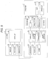
Fig. 5 is a block diagram illustrating functions of the infusion device illustrated inFig. 4 . - Hereinafter, an infusion device and a syringe pump according to an embodiment of the present invention will be described in detail with reference to the drawings.
- First, an
infusion device 1 and asyringe pump 2 according to a first embodiment of the present invention will be described in detail with reference toFigs. 1 to 3 . As illustrated inFig. 1 , theinfusion device 1 according to this embodiment includes thesyringe pump 2, aninfusion bag 3, and afluid sensor 4. - The
syringe pump 2 is configured to hold asyringe 5 and be capable of delivering a second fluid contained in thesyringe 5 to aninfusion line 6 connected to theinfusion bag 3. The second fluid may be a predetermined drug which may cause a serious situation when the fluid to be delivered to a living body decreases in flow rate. Examples of the predetermined drug include anesthetics, hypertensive drugs, hypotensive drugs, and the like. Thesyringe 5 includes a cylindrical barrel 5a and aplunger 5b. The barrel 5a partitions an ejection hole and a hollow linked to the ejection hole. Theplunger 5b is to be inserted into the hollow of the barrel and pushed toward the ejection hole so that the second fluid inside the hollow is pushed out from the ejection hole. Thesyringe pump 2 includes asyringe clamp 2a that can fix the barrel 5a and aslider 2b that can press theplunger 5b toward the ejection hole. Thesyringe pump 2 also includes adisplay 2d included in anotification unit 2c that can notify outside of predetermined information to urge the replacement of theinfusion bag 3. Thedisplay 2d may be a display panel that can show various kinds of information or may be a touch panel that can accept various kinds of input. - The
infusion line 6 connects theinfusion bag 3 and a living body such as a human body. Theinfusion line 6 includes an indwelling member 7 such as an indwelling needle to be placed inside the living body. Theinfusion line 6 also includes a connecting member 8 having one end connected to theinfusion bag 3 and the other end connected to the indwelling member 7. The connecting member 8 may include, for example, a tube, a connector, and a coinfusion plug. The coinfusion plug included in the connecting member 8 is connected to one end of a coinfusion line 9 having the other end connected to the ejection hole of thesyringe 5. - The
infusion bag 3 contains a first fluid L including a predetermined component according to the intended use. In this embodiment, the first fluid L contained in theinfusion bag 3 is delivered to the living body by gravity drip. However, an infusion pump may be disposed on theinfusion line 6, and the first fluid L may be delivered by the infusion pump. - The
fluid sensor 4 is configured to be capable of transmitting a predetermined signal (hereinafter also referred to as "first signal") when a residual volume of the first fluid L contained in theinfusion bag 3 is equal to or less than a predetermined volume. Furthermore, thefluid sensor 4 is configured to be capable of transmitting another signal different from the first signal (hereinafter also referred to as "second signal") when the residual volume of the first fluid L exceeds the predetermined volume. Thefluid sensor 4 in this embodiment is an ultrasonic sensor disposed in theinfusion bag 3. Thefluid sensor 4 is not limited to such an ultrasonic sensor and may be, for example, a capacitance sensor that can detect changes of capacitance inside theinfusion bag 3. Thefluid sensor 4 in this embodiment is connected to thesyringe pump 2 by acable 10. Thefluid sensor 4 is attachable to and detachable from theinfusion bag 3 by a double-sided tape or the like. - As illustrated in
Fig. 2 , thefluid sensor 4 includes asensor unit 4a provided with an ultrasonic transmitter that can transmit an ultrasonic wave to the inside of theinfusion bag 3 and an ultrasonic receiver that can receive a reflected wave of the ultrasonic wave transmitted from the ultrasonic transmitter. Thesyringe pump 2 includes acommunication unit 2e that can receive the first signal from thefluid sensor 4. Thefluid sensor 4 includes acommunication unit 4b that can communicate with thecommunication unit 2e. Thecommunication unit 2e of thesyringe pump 2 can receive via thecable 10 either the first signal or the second signal from thecommunication unit 4b of thefluid sensor 4 depending on the residual volume of the first fluid L. Thefluid sensor 4 is connected to apower source 2f disposed in thesyringe pump 2 via thecable 10 and can operate by electric power from thepower source 2f. - The
syringe pump 2 includes thedisplay 2d and asound output unit 2g as components of thenotification unit 2c. Thedisplay 2d can output predetermined visual information to urge the replacement of theinfusion bag 3. Thesound output unit 2g can output predetermined aural information to urge the replacement of theinfusion bag 3. Thenotification unit 2c may include either thedisplay 2d or thesound output unit 2g. - The
syringe pump 2 includes anoperation input unit 2h that can receive various kinds of input for making thesyringe pump 2 operates. Theoperation input unit 2h includes, for example, operation buttons. Part or all of theoperation input unit 2h may be a touch panel included in thedisplay 2d. - The
syringe pump 2 includes aslider driver 2i that drives theslider 2b and pushes out the second fluid from the ejection hole of thesyringe 5 while the barrel 5a of thesyringe 5 is fixed with the syringe clamp. Theslider driver 2i may include, for example, an electric motor. - The
syringe pump 2 includes acontrol unit 2k connected to thecommunication unit 2e, thepower source 2f, thedisplay 2d, thesound output unit 2g, theoperation input unit 2h, theslider driver 2i, and amemory 2j. Thecontrol unit 2k can control the operations of, for example, thepower source 2f, theslider driver 2i, thedisplay 2d, and thesound output unit 2g according to input from theoperation input unit 2h and a program stored in thememory 2j. Thecontrol unit 2k also controls the operation of thesensor unit 4a of thefluid sensor 4 via thecommunication unit 2e and thecommunication unit 4b. - The
control unit 2k includes anotification control unit 21, adetermination unit 2m, and adelivery control unit 2n. Thenotification control unit 21 is configured to cause thenotification unit 2c to notify of the predetermined information when thecommunication unit 2e receives the first signal. Thedetermination unit 2m is configured to determine whether the second fluid is the predetermined drug. The second fluid can be detected by, for example, configuring thesyringe pump 2 so that thecommunication unit 2e reads information such as a product ID of the second fluid stored in a tag disposed in the syringe. Alternatively, thesyringe pump 2 may be configured to be capable of acquiring the information such as the product ID of the second fluid from a library built in, for example, a server or a personal computer via thecommunication unit 2e. Alternatively, thesyringe pump 2 may be configured so that the information such as the product ID of the second fluid is input by a user via theoperation input unit 2h. The predetermined drug can be set by, for example, configuring thesyringe pump 2 so that a user inputs information such as a product ID of the predetermined drug via theoperation input unit 2h. The input information associated with the predetermined drug is stored in thememory 2j. The information associated with the predetermined drug may be stored in thememory 2j in advance without input from the user. Thedelivery control unit 2n is configured to be capable of controlling delivery of the second fluid to theinfusion line 6. In this embodiment, when thedetermination unit 2m determines that the second fluid is the predetermined drug, thedelivery control unit 2n is configured not to start delivering the second fluid to theinfusion line 6 until thecommunication unit 2e receives the second signal. However, thedelivery control unit 2n may be configured not to control initiation of the second fluid delivery. - The
control unit 2k in this embodiment includes a central processing unit (CPU). Note that thecontrol unit 2k may include, for example, a plurality of processing units. - The
infusion device 1 can operate in a manner illustrated inFig. 3 . First, in step S1, thecontrol unit 2k determines whether initiation of the second fluid delivery is input to theoperation input unit 2h. Determining that there is input ("Yes" in step S1), thecontrol unit 2k proceeds to step S2. On the other hand, when thecontrol unit 2k determines that there is no input ("No" in step S1), step S1 is repeated. - In step S2, the
control unit 2k (determination unit 2m) determines whether the second fluid is the predetermined drug. Determining that the second fluid is the predetermined drug ("Yes" in step S2), thecontrol unit 2k (determination unit 2m) proceeds to step S3. On the other hand, when thecontrol unit 2k determines that the second fluid is not the predetermined drug ("No" in step S2), thecontrol unit 2k proceeds to step S4. - In step S3, the
control unit 2k (delivery control unit 2n) determines whether another signal (second signal) is received. Determining that the second signal is received ("Yes" in step S2), thecontrol unit 2k (delivery control unit 2n) proceeds to step S4 and starts delivering the second fluid. On the other hand, when thecontrol unit 2k determines that the second signal is not received ("No" in step S3), step S3 is repeated. - As described above, in this embodiment, when the second fluid is the predetermined drug such as an anesthetic, the second fluid is not delivered until it is determined that the second signal is received, that is, until the
fluid sensor 4 is disposed in theinfusion bag 3 and the residual volume of the first fluid L contained in theinfusion bag 3 is determined to be over the predetermined volume. Accordingly, when the second fluid is the predetermined drug and when the attachment of thefluid sensor 4 to theinfusion bag 3 is forgotten, it is possible to prevent the initiation of the second fluid delivery. In addition, when the second fluid is not the predetermined drug, it is possible to administer the second fluid to a living body without using thefluid sensor 4. In this case, the administering of the second fluid may be performed via theinfusion line 6 or directly without theinfusion line 6. - The
control unit 2k may be configured not to perform the processes from step S2 to step S3. In this case, if "Yes" in step S1, thecontrol unit 2k proceeds to step S4, skipping steps S2 and S3. - After the second fluid delivery is started in step S4, the
control unit 2k proceeds to step S5. In step S5, thecontrol unit 2k determines whether the predetermined signal (first signal) is received. Determining that the predetermined signal (first signal) is received ("Yes" in step S5), thecontrol unit 2k proceeds to step S6 and notifies of the predetermined information. On the other hand, when thecontrol unit 2k determines that the first signal is not received ("No" in step S5), step S5 is repeated. - In this manner, the
control unit 2k can cause thenotification unit 2c to notify of the predetermined information when the first signal is received, that is, when the residual volume inside theinfusion bag 3 is equal to or less than the predetermined volume. In this embodiment, this notification is performed by thesyringe pump 2 itself configured to administer the predetermined drug which may cause a serious situation when theinfusion bag 3 is not replaced. Therefore, according to this embodiment, it is possible to urge a medical staff to replace theinfusion bag 3, which reliably achieves the intended effect of the predetermined drug administered by thesyringe pump 2. - The
infusion device 1 and thesyringe pump 2 according to this embodiment can be modified in various ways. For example, in this embodiment, thefluid sensor 4 is configured to be capable of transmitting the second signal when the residual volume of the first fluid L exceeds the predetermined volume, and thesyringe pump 2 includes thedetermination unit 2m that determines whether the second fluid is the predetermined drug. When thedetermination unit 2m determines that the second fluid is the predetermined drug, thedelivery control unit 2n is configured not to start delivering the second fluid to theinfusion line 6 until thecommunication unit 2e receives the second signal. However, thesyringe pump 2 may not include thedetermination unit 2m that determines whether the second fluid is the predetermined drug, and thedelivery control unit 2n may be configured not to start delivering the second fluid to theinfusion line 6 until thecommunication unit 2e receives the second signal. - Furthermore, the
fluid sensor 4 may not be configured to be capable of transmitting the second signal when the residual volume of the first fluid L exceeds the predetermined volume. In this case, thedetermination unit 2m of thesyringe pump 2 may be configured to determine whether thecommunication unit 2e and thefluid sensor 4 are communicably connected to each other and determine whether the second fluid is the predetermined drug. When thedetermination unit 2m determines that the second fluid is the predetermined drug, thedelivery control unit 2n may be configured not to start delivering the second fluid to theinfusion line 6 until thedetermination unit 2m determines that thecommunication unit 2e and thefluid sensor 4 are communicably connected to each other. Thedetermination unit 2m of thesyringe pump 2 may be configured to determine whether thecommunication unit 2e and thefluid sensor 4 are communicably connected to each other and not to determine whether the second fluid is the predetermined drug. Thedelivery control unit 2n may be configured not to start delivering the second fluid to theinfusion line 6 until thedetermination unit 2m determines that thecommunication unit 2e and thefluid sensor 4 are communicably connected to each other. - Next, an infusion device 1' and a syringe pump 2' according to a second embodiment of the present invention will be described in detail with reference to
Figs. 4 to 5 . As illustrated inFig. 4 , an infusion device 1' according to this embodiment is similar to theinfusion device 1 according to the first embodiment except that a syringe pump 2' and a fluid sensor 4' are wirelessly connected to each other. InFigs. 4 to 5 , components similar to those in the first embodiment are denoted by the same reference numerals as the first embodiment. - As illustrated in
Fig. 5 , in this embodiment, the fluid sensor 4' includes thesensor unit 4a, acommunication unit 4b', apower source 4c, and acontrol unit 4d. Thecontrol unit 4d is connected to thesensor unit 4a, thecommunication unit 4b', and thepower source 4c and configured to be capable of controlling operations of those members. Thecontrol unit 4d in this embodiment includes a microcontroller. - In this embodiment, a
communication unit 2e' of the syringe pump 2' is configured to wirelessly be capable of communicating with thecommunication unit 4b' of the fluid sensor 4' by, for example, Bluetooth (registered trademark). In other words, thecommunication unit 2e' of the syringe pump 2' can receive by wireless communication either a first signal or a second signal from thecommunication unit 4b' of the fluid sensor 4' depending on the residual volume of a first fluid L. The other configurations of the syringe pump 2' are similar to those of thesyringe pump 2 in the first embodiment. - The infusion device 1' can be operated in a similar manner to the
infusion device 1 in the first embodiment. Therefore, the infusion device 1' according to the second embodiment can achieve effects similar to theinfusion device 1 according to the first embodiment. The infusion device 1' according to the second embodiment can variously be modified in a similar manner to theinfusion device 1 in the first embodiment. - The aforementioned embodiments are illustrated as exemplary embodiments of the present invention, and it goes without saying that the present invention may employ various modifications without departing from the gist of the invention.
-
- 1, 1'
- Infusion device
- 2, 2'
- Syringe pump
- 2a
- Syringe clamp
- 2b
- Slider
- 2c
- Notification unit
- 2d
- Display
- 2e, 2e'
- Communication unit
- 2f
- Power source
- 2g
- Sound output unit
- 2h
- Operation input unit
- 2i
- Slider driver
- 2j
- Memory
- 2k
- Control unit
- 21
- Notification control unit
- 2m
- Determination unit
- 2n
- Delivery control unit
- 3
- Infusion bag
- 4, 4'
- Fluid sensor
- 4a
- Sensor unit
- 4b, 4b'
- Communication unit
- 4c
- Power source
- 4d
- Control unit
- 5
- Syringe
- 5a
- Barrel
- 5b
- Plunger
- 6
- Infusion line
- 7
- Indwelling member
- 8
- Connecting member
- 9
- Coinfusion line
- 10
- Cable
- L
- First fluid
Claims (7)
- An infusion device comprising:an infusion bag configured to contain a first fluid;a syringe pump configured to hold a syringe and be capable of delivering a second fluid contained in the syringe to an infusion line connected to the infusion bag; anda fluid sensor configured to be capable of transmitting a predetermined signal when a residual volume of the first fluid contained in the infusion bag is equal to or less than a predetermined volume,wherein the syringe pump comprises:a communication unit configured to be capable of receiving the predetermined signal from the fluid sensor;a notification unit configured to be capable of notifying outside of predetermined information; anda notification control unit configured to cause the notification unit to notify of the predetermined information when the communication unit receives the predetermined signal.
- The infusion device according to claim 1,
wherein the syringe pump comprises:a delivery control unit configured to be capable of controlling delivery of the second fluid to the infusion line; anda determination unit configured to determine whether the communication unit and the fluid sensor are communicably connected to each other,the delivery control unit being configured not to start delivering the second fluid to the infusion line until the determination unit determines that the communication unit and the fluid sensor are communicably connected to each other. - The infusion device according to claim 1,
wherein the syringe pump comprises:a delivery control unit configured to be capable of controlling delivery of the second fluid to the infusion line; anda determination unit configured to determine whether the communication unit and the fluid sensor are communicably connected to each other and determine whether the second fluid is a predetermined drug,the delivery control unit being configured not to start delivering the second fluid to the infusion line until the determination unit determines that the communication unit and the fluid sensor are communicably connected to each other when the determination unit determines that the second fluid is the predetermined drug. - The infusion device according to claim 1,
wherein the fluid sensor is capable of transmitting another signal different from the predetermined signal when the residual volume of the first fluid exceeds the predetermined volume, and
the syringe pump includes a delivery control unit configured to be capable of controlling delivery of the second fluid to the infusion line,
the delivery control unit being configured not to start delivering the second fluid to the infusion line until the communication unit receives the other signal. - The infusion device according to claim 1,
wherein the fluid sensor is capable of transmitting another signal different from the predetermined signal when the residual volume of the first fluid exceeds the predetermined volume, and
the syringe pump comprises:a determination unit configured to determine whether the second fluid is a predetermined drug; anda delivery control unit configured to be capable of controlling delivery of the second fluid to the infusion line,the delivery control unit being configured not to start delivering the second fluid to the infusion line until the communication unit receives the other signal when the determination unit determines that the second fluid is the predetermined drug. - The infusion device according to any one of claims 1 to 5, wherein the fluid sensor is an ultrasonic sensor disposed in the infusion bag.
- A syringe pump configured to hold a syringe and be capable of delivering a second fluid contained in the syringe to an infusion line connected to an infusion bag that contains a first fluid, the syringe pump comprising:a communication unit configured to be capable of receiving a predetermined signal from a fluid sensor when a residual volume of the first fluid contained in the infusion bag is equal to or less than a predetermined volume;a notification unit configured to be capable of notifying outside of predetermined information; anda notification control unit configured to cause the notification unit to notify of the predetermined information when the communication unit receives the predetermined signal.
Applications Claiming Priority (2)
| Application Number | Priority Date | Filing Date | Title |
|---|---|---|---|
| JP2018065569 | 2018-03-29 | ||
| PCT/JP2019/004481 WO2019187690A1 (en) | 2018-03-29 | 2019-02-07 | Infusion device and syringe pump |
Publications (2)
| Publication Number | Publication Date |
|---|---|
| EP3747485A1 true EP3747485A1 (en) | 2020-12-09 |
| EP3747485A4 EP3747485A4 (en) | 2021-04-28 |
Family
ID=68061157
Family Applications (1)
| Application Number | Title | Priority Date | Filing Date |
|---|---|---|---|
| EP19778245.1A Withdrawn EP3747485A4 (en) | 2018-03-29 | 2019-02-07 | Infusion device and syringe pump |
Country Status (4)
| Country | Link |
|---|---|
| EP (1) | EP3747485A4 (en) |
| JP (1) | JPWO2019187690A1 (en) |
| CN (1) | CN111601628B (en) |
| WO (1) | WO2019187690A1 (en) |
Families Citing this family (1)
| Publication number | Priority date | Publication date | Assignee | Title |
|---|---|---|---|---|
| JP7484160B2 (en) * | 2019-12-20 | 2024-05-16 | ニプロ株式会社 | Pump System |
Family Cites Families (16)
| Publication number | Priority date | Publication date | Assignee | Title |
|---|---|---|---|---|
| US4094318A (en) * | 1976-07-09 | 1978-06-13 | Burron Medical Products, Inc. | Electronic control means for a plurality of intravenous infusion sets |
| JPS6443936U (en) * | 1987-09-11 | 1989-03-16 | ||
| DE3817411A1 (en) * | 1988-05-21 | 1989-11-30 | Fresenius Ag | MULTIPLE INFUSION SYSTEM |
| JPH0898885A (en) * | 1994-09-30 | 1996-04-16 | Top & Top:Kk | Electronic drip management drip bottle |
| EP1897574B1 (en) * | 2000-07-20 | 2012-09-05 | ACIST Medical Systems, Inc. | Syringe plunger locking mechanism |
| US20080154214A1 (en) * | 2006-12-22 | 2008-06-26 | Medrad, Inc. | Flow Based Pressure Isolation and Fluid Delivery System Including Flow Based Pressure Isolation |
| JP2008080036A (en) * | 2006-09-29 | 2008-04-10 | Terumo Corp | Pump for medical use |
| JP2009273502A (en) * | 2008-05-12 | 2009-11-26 | Jms Co Ltd | Medication monitoring apparatus |
| US20100114027A1 (en) * | 2008-11-05 | 2010-05-06 | Hospira, Inc. | Fluid medication delivery systems for delivery monitoring of secondary medications |
| TWI379799B (en) * | 2009-10-14 | 2012-12-21 | Inotera Memories Inc | Management system and method for judging correctness of substance in a bottle |
| US10911515B2 (en) * | 2012-05-24 | 2021-02-02 | Deka Products Limited Partnership | System, method, and apparatus for electronic patient care |
| JP5623762B2 (en) * | 2010-03-12 | 2014-11-12 | テルモ株式会社 | Pain relief device |
| WO2014104338A1 (en) * | 2012-12-28 | 2014-07-03 | 株式会社根本杏林堂 | Chemical liquid circuit and chemical liquid system using same |
| JP2015096098A (en) | 2013-11-15 | 2015-05-21 | 地方独立行政法人秋田県立病院機構 | Residual amount monitoring apparatus for infusion solution bag and residual amount monitoring method for infusion solution bag |
| JP2018082729A (en) * | 2015-03-26 | 2018-05-31 | テルモ株式会社 | Liquid medicine administration device |
| EP3266481B1 (en) * | 2016-07-08 | 2022-09-07 | Bayer Healthcare LLC | System and method for identifying a fill volume of a fluid chamber |
-
2019
- 2019-02-07 WO PCT/JP2019/004481 patent/WO2019187690A1/en not_active Ceased
- 2019-02-07 CN CN201980008731.1A patent/CN111601628B/en active Active
- 2019-02-07 JP JP2020510365A patent/JPWO2019187690A1/en active Pending
- 2019-02-07 EP EP19778245.1A patent/EP3747485A4/en not_active Withdrawn
Also Published As
| Publication number | Publication date |
|---|---|
| CN111601628B (en) | 2022-11-22 |
| WO2019187690A1 (en) | 2019-10-03 |
| JPWO2019187690A1 (en) | 2021-03-18 |
| EP3747485A4 (en) | 2021-04-28 |
| CN111601628A (en) | 2020-08-28 |
Similar Documents
| Publication | Publication Date | Title |
|---|---|---|
| US20220305200A1 (en) | Infusion pump system and method with common line auto flush | |
| US10765805B2 (en) | Infusion pump including pain controlled analgesic (“PCA”) apparatus | |
| US10646653B2 (en) | Injection device configured to mate with a mobile device | |
| MX2013014154A (en) | Method and system for alerting as to potential for bolus condition. | |
| US20150367071A1 (en) | Systems and methods for tracking and reversing accidental overdose | |
| KR20190115448A (en) | Drug injection device | |
| KR20160133774A (en) | Electronic handheld cylindrical drug infusion pump and the method of the same | |
| JP2023083324A (en) | Systems, methods and products for identifying lumens | |
| CN111263650B (en) | Controlling medical devices using wireless communication | |
| JP2022043872A (en) | Infusion device for animal | |
| JP2012179099A (en) | Medical pump | |
| CN111601628B (en) | Infusion device and syringe pump | |
| EP3103505A1 (en) | Joining unit for detecting needle disconnection | |
| US20160361500A1 (en) | Pharmaceutical injection device, medical support system and medical support method employing same | |
| CN111867655B (en) | Chemical liquid injection system, liquid chemical injection device, liquid chemical injection method and program | |
| KR101842598B1 (en) | Electronic handheld cylindrical drug infusion pump which is capable of detecting the damage caused by the impact | |
| JP2025522649A (en) | Drug delivery devices, systems and methods | |
| JP6438822B2 (en) | Chemical solution administration device | |
| JP5623762B2 (en) | Pain relief device | |
| WO2025184439A1 (en) | Intelligent infusion device with adjustable automation levels | |
| CN119524254A (en) | Anesthesia machine, infusion equipment, anesthesia system and control method thereof | |
| EP3501581A1 (en) | A drug delivery system and a method for operating a drug delivery system | |
| HK1215205A1 (en) | Disposable system for infusing drug with no catheter |
Legal Events
| Date | Code | Title | Description |
|---|---|---|---|
| STAA | Information on the status of an ep patent application or granted ep patent |
Free format text: STATUS: THE INTERNATIONAL PUBLICATION HAS BEEN MADE |
|
| PUAI | Public reference made under article 153(3) epc to a published international application that has entered the european phase |
Free format text: ORIGINAL CODE: 0009012 |
|
| STAA | Information on the status of an ep patent application or granted ep patent |
Free format text: STATUS: REQUEST FOR EXAMINATION WAS MADE |
|
| 17P | Request for examination filed |
Effective date: 20200831 |
|
| AK | Designated contracting states |
Kind code of ref document: A1 Designated state(s): AL AT BE BG CH CY CZ DE DK EE ES FI FR GB GR HR HU IE IS IT LI LT LU LV MC MK MT NL NO PL PT RO RS SE SI SK SM TR |
|
| AX | Request for extension of the european patent |
Extension state: BA ME |
|
| A4 | Supplementary search report drawn up and despatched |
Effective date: 20210329 |
|
| RIC1 | Information provided on ipc code assigned before grant |
Ipc: A61M 5/168 20060101AFI20210323BHEP Ipc: A61M 5/14 20060101ALI20210323BHEP Ipc: A61M 5/145 20060101ALI20210323BHEP |
|
| DAV | Request for validation of the european patent (deleted) | ||
| DAX | Request for extension of the european patent (deleted) | ||
| STAA | Information on the status of an ep patent application or granted ep patent |
Free format text: STATUS: EXAMINATION IS IN PROGRESS |
|
| 17Q | First examination report despatched |
Effective date: 20211203 |
|
| STAA | Information on the status of an ep patent application or granted ep patent |
Free format text: STATUS: THE APPLICATION HAS BEEN WITHDRAWN |
|
| 18W | Application withdrawn |
Effective date: 20220310 |