EP3747407B1 - Protection device for stent - Google Patents
Protection device for stent Download PDFInfo
- Publication number
- EP3747407B1 EP3747407B1 EP19747479.4A EP19747479A EP3747407B1 EP 3747407 B1 EP3747407 B1 EP 3747407B1 EP 19747479 A EP19747479 A EP 19747479A EP 3747407 B1 EP3747407 B1 EP 3747407B1
- Authority
- EP
- European Patent Office
- Prior art keywords
- stent
- grip
- protection device
- sheath
- fastener
- Prior art date
- Legal status (The legal status is an assumption and is not a legal conclusion. Google has not performed a legal analysis and makes no representation as to the accuracy of the status listed.)
- Active
Links
Images


Classifications
-
- A—HUMAN NECESSITIES
- A61—MEDICAL OR VETERINARY SCIENCE; HYGIENE
- A61F—FILTERS IMPLANTABLE INTO BLOOD VESSELS; PROSTHESES; DEVICES PROVIDING PATENCY TO, OR PREVENTING COLLAPSING OF, TUBULAR STRUCTURES OF THE BODY, e.g. STENTS; ORTHOPAEDIC, NURSING OR CONTRACEPTIVE DEVICES; FOMENTATION; TREATMENT OR PROTECTION OF EYES OR EARS; BANDAGES, DRESSINGS OR ABSORBENT PADS; FIRST-AID KITS
- A61F2/00—Filters implantable into blood vessels; Prostheses, i.e. artificial substitutes or replacements for parts of the body; Appliances for connecting them with the body; Devices providing patency to, or preventing collapsing of, tubular structures of the body, e.g. stents
- A61F2/0095—Packages or dispensers for prostheses or other implants
-
- A—HUMAN NECESSITIES
- A61—MEDICAL OR VETERINARY SCIENCE; HYGIENE
- A61F—FILTERS IMPLANTABLE INTO BLOOD VESSELS; PROSTHESES; DEVICES PROVIDING PATENCY TO, OR PREVENTING COLLAPSING OF, TUBULAR STRUCTURES OF THE BODY, e.g. STENTS; ORTHOPAEDIC, NURSING OR CONTRACEPTIVE DEVICES; FOMENTATION; TREATMENT OR PROTECTION OF EYES OR EARS; BANDAGES, DRESSINGS OR ABSORBENT PADS; FIRST-AID KITS
- A61F2/00—Filters implantable into blood vessels; Prostheses, i.e. artificial substitutes or replacements for parts of the body; Appliances for connecting them with the body; Devices providing patency to, or preventing collapsing of, tubular structures of the body, e.g. stents
- A61F2/82—Devices providing patency to, or preventing collapsing of, tubular structures of the body, e.g. stents
-
- A—HUMAN NECESSITIES
- A61—MEDICAL OR VETERINARY SCIENCE; HYGIENE
- A61F—FILTERS IMPLANTABLE INTO BLOOD VESSELS; PROSTHESES; DEVICES PROVIDING PATENCY TO, OR PREVENTING COLLAPSING OF, TUBULAR STRUCTURES OF THE BODY, e.g. STENTS; ORTHOPAEDIC, NURSING OR CONTRACEPTIVE DEVICES; FOMENTATION; TREATMENT OR PROTECTION OF EYES OR EARS; BANDAGES, DRESSINGS OR ABSORBENT PADS; FIRST-AID KITS
- A61F2/00—Filters implantable into blood vessels; Prostheses, i.e. artificial substitutes or replacements for parts of the body; Appliances for connecting them with the body; Devices providing patency to, or preventing collapsing of, tubular structures of the body, e.g. stents
- A61F2/95—Instruments specially adapted for placement or removal of stents or stent-grafts
- A61F2/9517—Instruments specially adapted for placement or removal of stents or stent-grafts handle assemblies therefor
-
- A—HUMAN NECESSITIES
- A61—MEDICAL OR VETERINARY SCIENCE; HYGIENE
- A61F—FILTERS IMPLANTABLE INTO BLOOD VESSELS; PROSTHESES; DEVICES PROVIDING PATENCY TO, OR PREVENTING COLLAPSING OF, TUBULAR STRUCTURES OF THE BODY, e.g. STENTS; ORTHOPAEDIC, NURSING OR CONTRACEPTIVE DEVICES; FOMENTATION; TREATMENT OR PROTECTION OF EYES OR EARS; BANDAGES, DRESSINGS OR ABSORBENT PADS; FIRST-AID KITS
- A61F2/00—Filters implantable into blood vessels; Prostheses, i.e. artificial substitutes or replacements for parts of the body; Appliances for connecting them with the body; Devices providing patency to, or preventing collapsing of, tubular structures of the body, e.g. stents
- A61F2/95—Instruments specially adapted for placement or removal of stents or stent-grafts
- A61F2/9522—Means for mounting a stent or stent-graft onto or into a placement instrument
-
- A—HUMAN NECESSITIES
- A61—MEDICAL OR VETERINARY SCIENCE; HYGIENE
- A61F—FILTERS IMPLANTABLE INTO BLOOD VESSELS; PROSTHESES; DEVICES PROVIDING PATENCY TO, OR PREVENTING COLLAPSING OF, TUBULAR STRUCTURES OF THE BODY, e.g. STENTS; ORTHOPAEDIC, NURSING OR CONTRACEPTIVE DEVICES; FOMENTATION; TREATMENT OR PROTECTION OF EYES OR EARS; BANDAGES, DRESSINGS OR ABSORBENT PADS; FIRST-AID KITS
- A61F2/00—Filters implantable into blood vessels; Prostheses, i.e. artificial substitutes or replacements for parts of the body; Appliances for connecting them with the body; Devices providing patency to, or preventing collapsing of, tubular structures of the body, e.g. stents
- A61F2/95—Instruments specially adapted for placement or removal of stents or stent-grafts
- A61F2/958—Inflatable balloons for placing stents or stent-grafts
-
- A—HUMAN NECESSITIES
- A61—MEDICAL OR VETERINARY SCIENCE; HYGIENE
- A61F—FILTERS IMPLANTABLE INTO BLOOD VESSELS; PROSTHESES; DEVICES PROVIDING PATENCY TO, OR PREVENTING COLLAPSING OF, TUBULAR STRUCTURES OF THE BODY, e.g. STENTS; ORTHOPAEDIC, NURSING OR CONTRACEPTIVE DEVICES; FOMENTATION; TREATMENT OR PROTECTION OF EYES OR EARS; BANDAGES, DRESSINGS OR ABSORBENT PADS; FIRST-AID KITS
- A61F2/00—Filters implantable into blood vessels; Prostheses, i.e. artificial substitutes or replacements for parts of the body; Appliances for connecting them with the body; Devices providing patency to, or preventing collapsing of, tubular structures of the body, e.g. stents
- A61F2/95—Instruments specially adapted for placement or removal of stents or stent-grafts
- A61F2/962—Instruments specially adapted for placement or removal of stents or stent-grafts having an outer sleeve
- A61F2/966—Instruments specially adapted for placement or removal of stents or stent-grafts having an outer sleeve with relative longitudinal movement between outer sleeve and prosthesis, e.g. using a push rod
-
- A—HUMAN NECESSITIES
- A61—MEDICAL OR VETERINARY SCIENCE; HYGIENE
- A61F—FILTERS IMPLANTABLE INTO BLOOD VESSELS; PROSTHESES; DEVICES PROVIDING PATENCY TO, OR PREVENTING COLLAPSING OF, TUBULAR STRUCTURES OF THE BODY, e.g. STENTS; ORTHOPAEDIC, NURSING OR CONTRACEPTIVE DEVICES; FOMENTATION; TREATMENT OR PROTECTION OF EYES OR EARS; BANDAGES, DRESSINGS OR ABSORBENT PADS; FIRST-AID KITS
- A61F2/00—Filters implantable into blood vessels; Prostheses, i.e. artificial substitutes or replacements for parts of the body; Appliances for connecting them with the body; Devices providing patency to, or preventing collapsing of, tubular structures of the body, e.g. stents
- A61F2/95—Instruments specially adapted for placement or removal of stents or stent-grafts
- A61F2/962—Instruments specially adapted for placement or removal of stents or stent-grafts having an outer sleeve
- A61F2/97—Instruments specially adapted for placement or removal of stents or stent-grafts having an outer sleeve the outer sleeve being splittable
-
- A—HUMAN NECESSITIES
- A61—MEDICAL OR VETERINARY SCIENCE; HYGIENE
- A61F—FILTERS IMPLANTABLE INTO BLOOD VESSELS; PROSTHESES; DEVICES PROVIDING PATENCY TO, OR PREVENTING COLLAPSING OF, TUBULAR STRUCTURES OF THE BODY, e.g. STENTS; ORTHOPAEDIC, NURSING OR CONTRACEPTIVE DEVICES; FOMENTATION; TREATMENT OR PROTECTION OF EYES OR EARS; BANDAGES, DRESSINGS OR ABSORBENT PADS; FIRST-AID KITS
- A61F2/00—Filters implantable into blood vessels; Prostheses, i.e. artificial substitutes or replacements for parts of the body; Appliances for connecting them with the body; Devices providing patency to, or preventing collapsing of, tubular structures of the body, e.g. stents
- A61F2/95—Instruments specially adapted for placement or removal of stents or stent-grafts
- A61F2/958—Inflatable balloons for placing stents or stent-grafts
- A61F2002/9583—Means for holding the stent on the balloon, e.g. using protrusions, adhesives or an outer sleeve
-
- A—HUMAN NECESSITIES
- A61—MEDICAL OR VETERINARY SCIENCE; HYGIENE
- A61F—FILTERS IMPLANTABLE INTO BLOOD VESSELS; PROSTHESES; DEVICES PROVIDING PATENCY TO, OR PREVENTING COLLAPSING OF, TUBULAR STRUCTURES OF THE BODY, e.g. STENTS; ORTHOPAEDIC, NURSING OR CONTRACEPTIVE DEVICES; FOMENTATION; TREATMENT OR PROTECTION OF EYES OR EARS; BANDAGES, DRESSINGS OR ABSORBENT PADS; FIRST-AID KITS
- A61F2250/00—Special features of prostheses classified in groups A61F2/00 - A61F2/26 or A61F2/82 or A61F9/00 or A61F11/00 or subgroups thereof
- A61F2250/0058—Additional features; Implant or prostheses properties not otherwise provided for
Definitions
- the present invention relates to the technical field of medical instruments and, more specifically, to a protection device for a stent.
- Bioabsorbable (biodegradable) polymer coronary stent products can bring benefits to the luminal diameter of coronary arteries and are suitable for use in the treatment of ischemic heart disease caused by primary coronary abnormalities.
- Such a bioabsorbable polymer stent product mainly consists of a polymer stent, a drug coating and a balloon-expandable delivery system.
- Stents are generally categorized into metal and polymer ones, and metal stents are further grouped into biodegradable and non-biodegradable. At present, most metal stents are non-biodegradable, while most polymer ones are biodegradable. In many therapeutic applications, once a commonly-used metal stent is implanted, it will permanently remain in the patient's body, posing long-term risks to the patient's health. By contrast, a polymer stent stays in the body only for a limited period of time during which the stent achieves its expected goal such as blood vessel patency or drug delivery.
- a biodegradable stent After achieving its therapeutic goal, a biodegradable stent will degrade into absorbable and metabolizable products in the body environment and eventually disappear.
- a stent Before a stent is delivered into a diseased blood vessel, it is configured in a squeezed state of being squeezed and secured onto the surface of a balloon. During use, the squeezed stent will be delivered along with the balloon to the diseased blood vessel, and the balloon is then inflated so that the stent expands synchronously with the balloon and finally presses against the vessel wall.
- Metal stents have good shape stability. Once a metal stent is squeezed to a certain diameter, it will substantially maintain the same diameter from then on. Therefore, metal stent products are basically free of the risk of diametrical expansion over time from packaging to use.
- polymer stents are made of polymeric materials that are more or less resilient, so they tend to experience more significant radial resilience after being moved from the presser. As a result, polymer stents will expand in radial dimension over time after being squeezed.
- traditional protective sheaths of a single-layered design tend to be unable to provide sufficient resistance to such expansions for stent diameter maintenance.
- US 2007/061001 A1 discloses a device for protecting the surface of a coated stent during its packaging, shipping, subsequent removal from the packaging and handling prior to introduction into a guiding catheter.
- US 2015/0088240 A1 discloses protective sheaths for scaffolds and stents crimped to a delivery balloon.
- the present invention provides a protection device for stent, comprising a sheath, a first grip and a second grip, the sheath being configured to hold a stent, the first grip is configured to be able to be driven to move toward the second grip to cause a first portion of the sheath to move away from a second portion thereof, so that the stent is allowed to be removed from the sheath.
- the first grip and the second grip are connected to each other by a connecting member.
- the connecting member is a spring, a spring strip or a shaft.
- the protection device for stent further comprising a first fastener and a second fastener, the first fastener being connected to the first grip, the second fastener being connected to the second grip, the first fastener and the second fastener being configured to engage each other to limit relative position of the first grip to the second grip.
- each of the first grip and the second grip is provided thereon with a number of anti-slipping means.
- an end of the first portion away from the first grip is integral with an end of the second portion away from the second grip.
- the first grip defines an axially-extending opening through which the second grip is inserted so that the second grip opposes the first grip.
- the connecting member is a spring strip with two ends disposed close to respective centers of the first grip and the second grip.
- the first portion and/or the second portion comprise(s) a frame and elastomer filler that is filled in the frame and defines a cavity for receiving the stent.
- the protection device for stent further comprising a protective layer provided on an inner surface of the sheath.
- the present invention further provides a medical device, comprising a stent squeezed within a balloon catheter, a coiled tube and a protection device for stent as defined above, the protection device being connected to the coiled tube.
- the coiled tube comprises an engagement tough configured to be received in the sheath so that the engagement tough and the first portion of the sheath together defines a cavity for receiving the stent, and wherein when the first portion and the second portion of the sheath are separated from each other, the protection device is removable from the coiled tube.
- the protection device further comprises fasteners that are secured to an outer surface of the coiled tube or clamped onto an inner surface of the coiled tube by elastic deformation.
- the protection device further comprises a protective layer provided on an inner surface of the sheath.
- the protection device for stent mainly includes the sheath and the first and second grips.
- the sheath is configured to hold a stent
- the first grip is able to be driven to move toward the second grip so that the first portion of the sheath is caused to move away from the second portion thereof, allowing removal of the stent from the sheath.
- the protection device for stent according to the present invention can be operated by only one hand to cause the first grip to move toward the second grip, resulting in the separation of the sheath's first portion from the sheath's second portions. This easy operation results in a significant improvement in operating efficiency.
- 1 denotes a protection device for stent; 10, a sheath; 100a, a first portion; 100b, a second portion; 101, an opening; 102, a slot; 11, a first grip; 12, a second grip; and 13, a cavity.
- FIGs. 3 to 9 and 13, 2 denotes a protection device for stent; 20, sheath; 200a, a first portion; 200b, a second portion; 201, a slit; 21, a first grip; 22, a second grip; 23, a cavity; 24, a protective layer; 25, a connecting member; 26, a first fastener; 27, a second fastener; 4, a coiled tube; and 40, an engagement tough.
- 3 denotes a protection device for stent; 30, a sheath; 300a, a frame; 300b, elastomer filler; 300c, a fastener; 301, a slit; 31, a first grip; 32, a second grip; 33, a cavity; 34, a protective layer; 5, a stent; and 6, a balloon catheter.
- the protection device for stent includes a sheath, a first grip and a second grip.
- the sheath is configured to hold a stent, and the first grip can be driven to move toward the second grip so that a first portion of the sheath is caused to move away from a second portion thereof, allowing removal of the stent from the sheath.
- the first portion and/or the second portion include(s) a frame and elastomer filler that is filled in the frame and define a cavity for receiving the stent.
- the protection device for stent of the present invention will be better understood from the following description of a few specific examples.
- the protection device for stent 1 includes a sheath 10, a first grip 11 and a second grip 12.
- the sheath 10 is configured to hold a stent and includes first and second portions connected to each other.
- the first grip 11 can be driven to move toward the second grip 12 so that the first portion of the sheath 10 is caused to move away from the second portion thereof, allowing removal of the stent from the sheath 10.
- the first grip 11 is formed of an extension of the first portion of the sheath 10, whilst the second grip 12 is formed of an extension of the second portion of the sheath 10.
- the first and second portions are integral with each other at their respective sides away from the first and second grips, respectively.
- the first grip 11 defines an axially-extending opening 101, through which the second grip 12 is inserted and opposes the first grip 11.
- the second grip 12 may define an axially-extending opening, through which the first grip 11 is inserted and opposes the second grip 12.
- a number of anti-slipping means are preferably provided on the first and second grips 11, 12 so that some of them are arranged on a side of the first grip 11 facing away from the second grip 12, and the rest on a side of the second grip 12 facing away from the first grip 11.
- the sheath 10 may define an axially-extending slot 102 having two edges opposing each other along a circumferential direction of the sheath 10 (and respectively forming an end of the first portion close to the first grip and an end of the second portion close to the second grip).
- the first and second grips 11, 12 may be connected respectively to these edges, with one being inserted into the other, so that they bridge the slot and define (delimit), together with the sheath 10, a cavity 13 that retrains the stent's resilience.
- the cavity 13 delimited by the sheath 10, the first grip 11 and the second grip 12 restrains the stent's resilience by providing radial compressive forces, and the bridging of the slot 102 by the first and second grips 12 that are inserted one into the other provides radial support for maintain a circular cross-section of the stent.
- the first and second grips 11, 12 are also allowed to each have a significantly reduced width (perpendicular to an axis of the protection device 1) so as to allow the protection device to be loaded in (i.e., accommodated within) another structure.
- the sheath 10 and the first and second grips 11, 12 may be formed by forging and cutting a metal sheet, or by molding a polymeric material.
- the metal sheet is preferably made of alloy(s) with good biocompatibility, such as at least one of a stainless steel, a nickel-titanium alloy and a magnesium alloy.
- the polymeric material is preferably a polymeric material with good biocompatibility containing, for example, at least one of PTFE, Pebax, polyethylene, polycarbonate, polyamide and nylon.
- the sheath 10 may appear as a hollow tube, and the stent is held therein in a squeezed state where its outer diameter is equal to an inner diameter of the sheath 10.
- the sheath 10 may have a length that is greater than or equal to a length of the squeezed stent so that it is able to entirely cover an outer surface of the stent and apply a constraining force radially to the squeezed stent, thus better restraining the stent's radial resilience.
- step S11 external forces are exerted on the first and second grips 11, 12 so that the first grip 11 moves toward the second grip 12, causing the free ends of the first and second portions of the sheath 10 to move away from each other (manifested as an expansion of the slot 102 and a diametrical expansion of the cavity 13 that restrains the stent's resilience).
- step S12 the stent is removed from the sheath 10.
- the operator may press the first and second grips 11, 12, with the thumb and index finger, respectively, in the directions indicated by the arrows in the Fig. 1 .
- the first grip 11 will move toward the second grip 12, causing the free ends of the first and second portions of the sheath 10 to move away from each other.
- a protection device for stent according to a second embodiment is structurally different from that of Embodiment 1 in further including a connecting member, in addition to a sheath, a first grip and a second grip.
- the connecting member connects the first and second grips to each other.
- the connecting member is a metal member.
- Fig. 3 a schematic illustration of a first structural variant of the protection device for stent according to this embodiment.
- the sheath 20 is split by a slit 201 into a first portion 200a and a second portion 200b that are separable from each other.
- the sheath 20 appears as a hollow tube and has a length that is greater than or equal to a length of a squeezed stent load therein, so that it is able to entirely cover an outer surface of the stent and apply a constraining force radially to the squeezed stent, thus better restraining the stent's radial resilience.
- the stent when squeezed and secured to a balloon in a delivery system, it can maintain a diametrical dimension favorable to the delivery system up until the time when the stent system is delivered to a target site within a body.
- the connecting member 25 connecting the first and second grips 21, 22 is preferably a spring tending to resist the pressure force that would cause opposing movements of the first and second grip 21, 22 and maintain the connection between the first and second portions 200a, 200b. This can ensure the stability of the cavity 23 that restrains the stent's resilience.
- the pressure force is greater than the resistance threshold of the spring, the first and second portions 200a, 200b will move away from each other, leading to a diametrical expansion of the cavity 23 that restrains the stent's resilience.
- the connecting member 25 is not limited to being a spring, because it can be any one of multiple structures including, for example, a spring strip or a shaft, as in particular shown in Figs. 6 to 9 .
- Fig. 6 a schematic illustration of a second structural variant of the protection device for stent according to this embodiment
- Fig. 7 a side view of the protection device for stent of Fig. 6 .
- the protection device for stent 2 shown in Figs. 6 and 7 differs from that in Fig. 3 in the structure of the connecting member 25.
- the connecting member 25 is a shaft such as a pin shaft.
- the first grip 21 is connected to the first portion 200a to form a first piece
- the second grip 22 is connected to the second portion 200b to form a second piece.
- the shaft extends through an overlap between the first and second pieces.
- the protection device for stent 2 further includes a first fastener 26 and a second fastener 27.
- the first fastener 26 is connected to the first grip 21, while the second fastener 27 is connected to the second grip 22.
- FIG. 8 a schematic illustration of a third structural variant of the protection device for stent according to this embodiment
- Fig. 9 a side view of the protection device for stent of Fig. 8
- the protection device for stent 2 shown in Figs. 8 and 9 differs from those in Fig. 3 and in Figs. 6 and 7 in the overall structure of the protection device and in the structure of the connecting member 25.
- the connecting member 25 is a spring strip with ends disposed close to respective centers of the first and second grips.
- the spring strip is curved and defines an opening in which the sheath 20 is secured.
- Fig. 8 a schematic illustration of a third structural variant of the protection device for stent according to this embodiment
- Fig. 9 a side view of the protection device for stent of Fig. 8
- the protection device for stent 2 shown in Figs. 8 and 9 differs from those in Fig. 3 and in Figs. 6 and 7 in the overall structure of the protection device and in the structure of the
- the opening has two edges fixedly connected respectively to the first and second portions 200a, 200b.
- the first and second portions 200a, 200b are axisymmetric, and the two edges of the opening are further fixedly connected respectively to the first and second grips 21, 22.
- the first and second grips 21, 22 are axisymmetric.
- the spring strip provides a resistance force in response to the opposing movements of the first and second grip 21, 22, causing an expansion of the opening of the spring strip.
- the first and second portions 200a, 200b moves away from each other, and the cavity 23 that restrains the stent's resilience experiences a diametrical expansion.
- the spring strip is C-shaped.
- the protection device may further include a protective layer 24 disposed on an inner surface of the sheath 20 (i.e., surrounding an outer surface of the stent 5).
- the protective layer 24 can not only provide protection to the stent 5, but also allows the sheath 20 to apply a higher preload to the stent 5.
- the sheath 20 is a metal sheath or a polymer sheath, with the first and second grips 21, 22 being both metal grips, and with the protective layer 24 being a polymer film wrapping the outer surface of the stent and insulating it from the sheath.
- FIG. 10 a schematic illustration of a fourth structural variant of the protection device for stent according to this embodiment.
- the protection device for stent of Fig. 10 differs from that of Fig. 8 in (i) omitting the connecting member, with the sheath providing the functions of the connecting member instead and (ii) differences in the structures of the first and second portions.
- the sheath 30 of the protection device for stent 3 is split by a slit 301 into first and second portions with respective ends separable from each other.
- the first and second portions are integral with each other at the respective other ends. That is, the slit 301 extends from an outer surface of the sheath 30 radially into the cavity 33.
- the first and second portions include a frame 300a and elastomer filler 300b that is filled within the frame 300a and defines the cavity for receiving the stent.
- the first and second grips 31, 32 are disposed on opposing sides of the frame 300a. As shown in Fig. 11 , in the process that the sheath 30 resists the pressure force on the first and second grips 31, 32, the sheath 30 will elastically deform, causing a diametrical expansion of the cavity 33 and thus allowing removal of the stent from the sheath 30.
- the protection device for stent 3 may further include a protective layer 34 disposed on an inner surface of the sheath 30 (i.e., surrounding an outer surface of the stent 5).
- the protective layer 34 can not only provide protection to the stent 5, but also allows the sheath 30 to apply a higher preload to the stent 5.
- the protection device for stent 3 may further include fasteners 300c enabling engagement with other components.
- Each fastener 300c can be structured as needed, and the present invention is not limited to any particular structure thereof.
- a medical device including a stent 5 squeezed within a balloon catheter 6, a coiled tube 4 and any of the protection devices for stent as described in Embodiment 1 and 2.
- the protection device for stent is coupled to the coiled tube 4.
- the medical device includes the protection device for stent 2 shown in Fig. 3 .
- the coiled tube 4 includes an engagement tough 40 configured to be received in the sheath 20 so that the coiled tube 4 defines the stent cavity 23 together with the first portion 200a of the sheath 20.
- the protection device for stent 2 can be removed from the coiled tube 4.
- the engagement of the protection device for stent with the coiled tube is not limited to being accomplished by the structure shown in Fig. 3 in which the engagement tough 40 and the first portion 200a of the sheath 20 together delimits the stent cavity.
- a groove that can engage the engagement tough 40 may be formed in the first or second portion so that the first and second portions together delimit the stent cavity.
- the protection device for stent may further include fasteners 300c, which are fastened to an outer surface of the coiled tube or clamped onto an inner surface of the coiled tube by elastic deformation.
- Embodiment 3 employs a protection device for stent of Embodiment 1 or 2, it is described relatively briefly, and reference can be made to the related description of Embodiment 1 or 2 for more details in Embodiment 3.
- the methods described in the embodiments correspond to the respective structures in the embodiments, they are described relatively briefly, and reference can be made to the related description of the structures for more details in the methods.
- the protection device for stent mainly includes the sheath and the first and second grips.
- the sheath is configured to hold a stent
- the first grip is able to be driven to move toward the second grip so that the first portion of the sheath is caused to move away from the second portion thereof, allowing removal of the stent from the sheath.
- the protection device for stent can be operated by only one hand to cause the first grip to move toward the second grip, resulting in the separation of the sheath's first portion from the sheath's second portions. This easy operation results in a significant improvement in operating efficiency.
- a diametrical expansion resulting from the opposing movements of the first and second grips allows the stent to be removed from the protection device without sliding contact between them. This can effectively avoid damage to the stent or its surface coating.
- the fasteners can provide stable support to the sheath for a long term, thus avoiding radial resilience of the stent due to deformation of the sheath during storage.
Landscapes
- Health & Medical Sciences (AREA)
- Engineering & Computer Science (AREA)
- Biomedical Technology (AREA)
- Cardiology (AREA)
- Oral & Maxillofacial Surgery (AREA)
- Transplantation (AREA)
- Heart & Thoracic Surgery (AREA)
- Vascular Medicine (AREA)
- Life Sciences & Earth Sciences (AREA)
- Animal Behavior & Ethology (AREA)
- General Health & Medical Sciences (AREA)
- Public Health (AREA)
- Veterinary Medicine (AREA)
- Media Introduction/Drainage Providing Device (AREA)
- Prostheses (AREA)
Description
- The present invention relates to the technical field of medical instruments and, more specifically, to a protection device for a stent.
- Bioabsorbable (biodegradable) polymer coronary stent products can bring benefits to the luminal diameter of coronary arteries and are suitable for use in the treatment of ischemic heart disease caused by primary coronary abnormalities. Such a bioabsorbable polymer stent product mainly consists of a polymer stent, a drug coating and a balloon-expandable delivery system.
- Stents are generally categorized into metal and polymer ones, and metal stents are further grouped into biodegradable and non-biodegradable. At present, most metal stents are non-biodegradable, while most polymer ones are biodegradable. In many therapeutic applications, once a commonly-used metal stent is implanted, it will permanently remain in the patient's body, posing long-term risks to the patient's health. By contrast, a polymer stent stays in the body only for a limited period of time during which the stent achieves its expected goal such as blood vessel patency or drug delivery.
- After achieving its therapeutic goal, a biodegradable stent will degrade into absorbable and metabolizable products in the body environment and eventually disappear. Before a stent is delivered into a diseased blood vessel, it is configured in a squeezed state of being squeezed and secured onto the surface of a balloon. During use, the squeezed stent will be delivered along with the balloon to the diseased blood vessel, and the balloon is then inflated so that the stent expands synchronously with the balloon and finally presses against the vessel wall.
- Metal stents have good shape stability. Once a metal stent is squeezed to a certain diameter, it will substantially maintain the same diameter from then on. Therefore, metal stent products are basically free of the risk of diametrical expansion over time from packaging to use. On the other hand, polymer stents are made of polymeric materials that are more or less resilient, so they tend to experience more significant radial resilience after being moved from the presser. As a result, polymer stents will expand in radial dimension over time after being squeezed. However, traditional protective sheaths of a single-layered design tend to be unable to provide sufficient resistance to such expansions for stent diameter maintenance. Therefore, there is a need to address the challenges associated with securing a polymer stent to a delivery balloon and maintaining a diametrical dimension thereof favorable to the delivery system up until the time when the stent system is delivered to a target site within a body.
- Conventional stents such as that disclosed in
US2012109281A1 require complicated operations and suffer from a lack of compatibility with surgical environments. -
US 2007/061001 A1 discloses a device for protecting the surface of a coated stent during its packaging, shipping, subsequent removal from the packaging and handling prior to introduction into a guiding catheter.US 2015/0088240 A1 discloses protective sheaths for scaffolds and stents crimped to a delivery balloon. - Those skilled in the art have been long seeking solutions to the problem that conventional polymer stent products expand in radial dimension over time from packaging to use.
- The invention is set out in the appended set of claims.
- It is an objective of the present invention to provide a protection device for stent and a medical device, which can be operated easily and radially restrain and protect a stent.
- To solve the above technical problem, the present invention provides a protection device for stent, comprising a sheath, a first grip and a second grip, the sheath being configured to hold a stent, the first grip is configured to be able to be driven to move toward the second grip to cause a first portion of the sheath to move away from a second portion thereof, so that the stent is allowed to be removed from the sheath.
- Optionally, in the protection device for stent, the first grip is formed by extending the first portion, and the second grip is formed by extending the second portion.
- Optionally, in the protection device for stent, the first grip and the second grip are connected to each other by a connecting member.
- Optionally, in the protection device for stent, the connecting member is a spring, a spring strip or a shaft.
- Optionally, in the protection device for stent, further comprising a first fastener and a second fastener, the first fastener being connected to the first grip, the second fastener being connected to the second grip, the first fastener and the second fastener being configured to engage each other to limit relative position of the first grip to the second grip.
- Optionally, in the protection device for stent, each of the first grip and the second grip is provided thereon with a number of anti-slipping means.
- Optionally, in the protection device for stent, an end of the first portion away from the first grip is integral with an end of the second portion away from the second grip.
- Optionally, in the protection device for stent, the first grip defines an axially-extending opening through which the second grip is inserted so that the second grip opposes the first grip.
- Optionally, in the protection device for stent, the connecting member is a spring strip with two ends disposed close to respective centers of the first grip and the second grip.
- According to the invention, in the protection device for stent, the first portion and/or the second portion comprise(s) a frame and elastomer filler that is filled in the frame and defines a cavity for receiving the stent.
- Optionally, in the protection device for stent, further comprising a protective layer provided on an inner surface of the sheath.
- Accordingly, the present invention further provides a medical device, comprising a stent squeezed within a balloon catheter, a coiled tube and a protection device for stent as defined above, the protection device being connected to the coiled tube.
- Optionally, in the medical device, the coiled tube comprises an engagement tough configured to be received in the sheath so that the engagement tough and the first portion of the sheath together defines a cavity for receiving the stent, and wherein when the first portion and the second portion of the sheath are separated from each other, the protection device is removable from the coiled tube.
- Optionally, in the medical device, the protection device further comprises fasteners that are secured to an outer surface of the coiled tube or clamped onto an inner surface of the coiled tube by elastic deformation.
- Optionally, in the medical device, the protection device further comprises a protective layer provided on an inner surface of the sheath.
- In the protection device for stent and the medical device provided in the present invention, the protection device for stent mainly includes the sheath and the first and second grips. The sheath is configured to hold a stent, and the first grip is able to be driven to move toward the second grip so that the first portion of the sheath is caused to move away from the second portion thereof, allowing removal of the stent from the sheath. The protection device for stent according to the present invention can be operated by only one hand to cause the first grip to move toward the second grip, resulting in the separation of the sheath's first portion from the sheath's second portions. This easy operation results in a significant improvement in operating efficiency.
-
Figures 1 to 9 do not represent embodiments of the invention. -
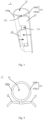
Fig. 1 is a structural schematic of a protection device for stent. -
Fig. 2 is a side view of the protection device for stent ofFig. 1 . -
Fig. 3 is a schematic illustration of a first structural variant of a protection device for stent. -
Fig. 4 is a structural schematic of a coiled tube. -
Fig. 5 is a structural schematic of the protection device for stent of theFig. 3 assembled with the coiled tube. -
Fig. 6 is a schematic illustration of a second structural variant of the protection device for stent. -
Fig. 7 is a side view of the protection device for stent ofFig. 6 . -
Fig. 8 is a schematic illustration of a third structural variant of the protection device for stent. -
Fig. 9 is a side view of the protection device for stent ofFig. 8 . -
Fig. 10 is a schematic illustration showing a side view of a fourth structural variant of the protection device for stent according to the present invention. -
Fig. 11 is a structural schematic of the protection device for stent ofFig. 10 , which has been operated by one hand to result in a diametrical expansion in a cavity that restrains resilience of a stent. -
Fig. 12 is a side view of the protection device for stent ofFig. 10 additionally provided with fasteners. -
Fig. 13 is a structural schematic of the protection device for stent assembled with a stent and a balloon catheter. - In
Figs. 1 to 2 , 1 denotes a protection device for stent; 10, a sheath; 100a, a first portion; 100b, a second portion; 101, an opening; 102, a slot; 11, a first grip; 12, a second grip; and 13, a cavity. - In
Figs. 3 to 9 and 13, 2 denotes a protection device for stent; 20, sheath; 200a, a first portion; 200b, a second portion; 201, a slit; 21, a first grip; 22, a second grip; 23, a cavity; 24, a protective layer; 25, a connecting member; 26, a first fastener; 27, a second fastener; 4, a coiled tube; and 40, an engagement tough. - In
Figs. 10 to 13 , 3 denotes a protection device for stent; 30, a sheath; 300a, a frame; 300b, elastomer filler; 300c, a fastener; 301, a slit; 31, a first grip; 32, a second grip; 33, a cavity; 34, a protective layer; 5, a stent; and 6, a balloon catheter. - The protection device for stent proposed herein will be described in greater detail below by way of particular examples with reference to the accompanying drawings. Features and advantages of the invention will be more apparent from the following detailed description, and from the appended claims. Note that the figures are provided in a very simplified form not necessarily drawn to scale, with the only intention to facilitate convenience and clarity in explaining the examples. In particular, as the figures tend to have distinct emphases, they are often drawn to different scales.
- In this specification, when reference is made to a "stent", this term will refer to a squeezed stent. That is, a "squeezed stent" will be referred to as a "stent" hereinafter for short. The protection device for stent of the present invention can protect a squeezed stent while maintaining it to a diametrical dimension in favor of a delivery system.
- The protection device for stent includes a sheath, a first grip and a second grip. The sheath is configured to hold a stent, and the first grip can be driven to move toward the second grip so that a first portion of the sheath is caused to move away from a second portion thereof, allowing removal of the stent from the sheath.
- The first portion and/or the second portion include(s) a frame and elastomer filler that is filled in the frame and define a cavity for receiving the stent. The protection device for stent of the present invention will be better understood from the following description of a few specific examples.
- Reference is now made to
Fig. 1 , a structural schematic of a protection device for stent according to the present embodiment, and toFig. 2 , a side view of the protection device for stent ofFig. 1 . As illustrated inFigs. 1 and 2 , the protection device forstent 1 includes asheath 10, afirst grip 11 and asecond grip 12. Thesheath 10 is configured to hold a stent and includes first and second portions connected to each other. Thefirst grip 11 can be driven to move toward thesecond grip 12 so that the first portion of thesheath 10 is caused to move away from the second portion thereof, allowing removal of the stent from thesheath 10. Thefirst grip 11 is formed of an extension of the first portion of thesheath 10, whilst thesecond grip 12 is formed of an extension of the second portion of thesheath 10. The first and second portions are integral with each other at their respective sides away from the first and second grips, respectively. Thefirst grip 11 defines an axially-extendingopening 101, through which thesecond grip 12 is inserted and opposes thefirst grip 11. In another embodiment, thesecond grip 12 may define an axially-extending opening, through which thefirst grip 11 is inserted and opposes thesecond grip 12. - In order to increase friction on the first and
second grips second grips first grip 11 facing away from thesecond grip 12, and the rest on a side of thesecond grip 12 facing away from thefirst grip 11. - With continued reference to
Fig. 1 , in particular, thesheath 10 may define an axially-extendingslot 102 having two edges opposing each other along a circumferential direction of the sheath 10 (and respectively forming an end of the first portion close to the first grip and an end of the second portion close to the second grip). The first andsecond grips sheath 10, acavity 13 that retrains the stent's resilience. - The
cavity 13 delimited by thesheath 10, thefirst grip 11 and thesecond grip 12 restrains the stent's resilience by providing radial compressive forces, and the bridging of theslot 102 by the first andsecond grips 12 that are inserted one into the other provides radial support for maintain a circular cross-section of the stent. This effectively prevents radial resilience of the stent so that, when the stent is squeezed and secured to a balloon in a delivery system, it can maintain a diametrical dimension favorable to the delivery system (i.e., a diameter as when it was squeezed) up until the time when the stent system is delivered to a target site within a body. In addition, in the protection device forstent 1 of this embodiment, in addition to being inserted one into the other to bridge theslot 102 and delimit thecavity 13 that restrains the stent's resilience together with thesheath 10, the first andsecond grips - The
sheath 10 and the first andsecond grips sheath 10 may appear as a hollow tube, and the stent is held therein in a squeezed state where its outer diameter is equal to an inner diameter of thesheath 10. In addition, thesheath 10 may have a length that is greater than or equal to a length of the squeezed stent so that it is able to entirely cover an outer surface of the stent and apply a constraining force radially to the squeezed stent, thus better restraining the stent's radial resilience. - In order for better understanding the working principles of the protection device for stent according to the present invention, the operation of the protection device for
stent 1 of this embodiment will be described below in detail with reference toFigs. 1 and 2 . - First of all, in step S11, external forces are exerted on the first and
second grips first grip 11 moves toward thesecond grip 12, causing the free ends of the first and second portions of thesheath 10 to move away from each other (manifested as an expansion of theslot 102 and a diametrical expansion of thecavity 13 that restrains the stent's resilience). - Next, in step S12, the stent is removed from the
sheath 10. - Specifically, for example, this can be accomplished by only one hand of an operator. The operator may press the first and
second grips Fig. 1 . Under the pressure, thefirst grip 11 will move toward thesecond grip 12, causing the free ends of the first and second portions of thesheath 10 to move away from each other. This is manifested as movements of the two ends of theslot 102 opposing each other in the circumferential direction of thesheath 10 in the directions opposite to those indicated by the arrows, which results in an expansion of theslot 102 and a diametrical expansion of thecavity 13 that restrains the stent's resilience, making it possible to release the stent from constraints of thecavity 13 and thus from thesheath 10 in a contactless and frictionless manner. - A protection device for stent according to a second embodiment is structurally different from that of
Embodiment 1 in further including a connecting member, in addition to a sheath, a first grip and a second grip. The connecting member connects the first and second grips to each other. In this embodiment, the connecting member is a metal member. - Reference is now made to
Fig. 3 , a schematic illustration of a first structural variant of the protection device for stent according to this embodiment. As shown inFig. 3 , thesheath 20 is split by aslit 201 into afirst portion 200a and asecond portion 200b that are separable from each other. Thesheath 20 appears as a hollow tube and has a length that is greater than or equal to a length of a squeezed stent load therein, so that it is able to entirely cover an outer surface of the stent and apply a constraining force radially to the squeezed stent, thus better restraining the stent's radial resilience. In this way, when the stent is squeezed and secured to a balloon in a delivery system, it can maintain a diametrical dimension favorable to the delivery system up until the time when the stent system is delivered to a target site within a body. - With continued reference to
Fig. 3 , in the protection device forstent 2, the connectingmember 25 connecting the first andsecond grips second grip second portions cavity 23 that restrains the stent's resilience. When the pressure force is greater than the resistance threshold of the spring, the first andsecond portions cavity 23 that restrains the stent's resilience. - The connecting
member 25 is not limited to being a spring, because it can be any one of multiple structures including, for example, a spring strip or a shaft, as in particular shown inFigs. 6 to 9 . Reference is now made toFig. 6 , a schematic illustration of a second structural variant of the protection device for stent according to this embodiment, and toFig. 7 , a side view of the protection device for stent ofFig. 6 . The protection device forstent 2 shown inFigs. 6 and7 differs from that inFig. 3 in the structure of the connectingmember 25. As shown inFigs. 6 and7 , the connectingmember 25 is a shaft such as a pin shaft. Thefirst grip 21 is connected to thefirst portion 200a to form a first piece, and thesecond grip 22 is connected to thesecond portion 200b to form a second piece. The shaft extends through an overlap between the first and second pieces. In order for ensure robustness of the protection device, the protection device forstent 2 further includes afirst fastener 26 and asecond fastener 27. Thefirst fastener 26 is connected to thefirst grip 21, while thesecond fastener 27 is connected to thesecond grip 22. When thefirst fastener 26 engages thesecond fastener 27, the first andsecond grips second portions - Reference is now made to
Fig. 8 , a schematic illustration of a third structural variant of the protection device for stent according to this embodiment, and toFig. 9 , a side view of the protection device for stent ofFig. 8 . The protection device forstent 2 shown inFigs. 8 and9 differs from those inFig. 3 and inFigs. 6 and7 in the overall structure of the protection device and in the structure of the connectingmember 25. As shown inFigs. 8 and9 , the connectingmember 25 is a spring strip with ends disposed close to respective centers of the first and second grips. In this embodiment, the spring strip is curved and defines an opening in which thesheath 20 is secured. In particular, as shown inFig. 9 , the opening has two edges fixedly connected respectively to the first andsecond portions second portions second grips second grips second grip second portions cavity 23 that restrains the stent's resilience experiences a diametrical expansion. Preferably, the spring strip is C-shaped. - Reference is now made to
Fig. 13 , a structural schematic of the protection device for stent according to this embodiment assembled with a stent and a balloon catheter. As shown inFig. 13 , in order to avoid damage to a coating on the surface of thestent 5 during the removal of the stent from thesheath 20, the protection device according to this embodiment may further include a protective layer 24 disposed on an inner surface of the sheath 20 (i.e., surrounding an outer surface of the stent 5). The protective layer 24 can not only provide protection to thestent 5, but also allows thesheath 20 to apply a higher preload to thestent 5. Preferably, thesheath 20 is a metal sheath or a polymer sheath, with the first andsecond grips - Reference is now made to
Fig. 10 , a schematic illustration of a fourth structural variant of the protection device for stent according to this embodiment. The protection device for stent ofFig. 10 differs from that ofFig. 8 in (i) omitting the connecting member, with the sheath providing the functions of the connecting member instead and (ii) differences in the structures of the first and second portions. As shown inFig. 10 , thesheath 30 of the protection device forstent 3 is split by aslit 301 into first and second portions with respective ends separable from each other. The first and second portions are integral with each other at the respective other ends. That is, theslit 301 extends from an outer surface of thesheath 30 radially into thecavity 33. The first and second portions include aframe 300a andelastomer filler 300b that is filled within theframe 300a and defines the cavity for receiving the stent. The first andsecond grips frame 300a. As shown inFig. 11 , in the process that thesheath 30 resists the pressure force on the first andsecond grips sheath 30 will elastically deform, causing a diametrical expansion of thecavity 33 and thus allowing removal of the stent from thesheath 30. - As shown in
Fig. 13 , in order to avoid damage to a coating on the surface of thestent 5 during the removal of the stent from thesheath 30, the protection device forstent 3 according to this embodiment may further include a protective layer 34 disposed on an inner surface of the sheath 30 (i.e., surrounding an outer surface of the stent 5). The protective layer 34 can not only provide protection to thestent 5, but also allows thesheath 30 to apply a higher preload to thestent 5. - Referring to
Fig. 12 , on the basis of the structure shown inFig. 10 , the protection device forstent 3 may further includefasteners 300c enabling engagement with other components. Eachfastener 300c can be structured as needed, and the present invention is not limited to any particular structure thereof. - Referring to
Figs. 4 ,5 and13 , in an embodiment, there is provided a medical device including astent 5 squeezed within a balloon catheter 6, acoiled tube 4 and any of the protection devices for stent as described inEmbodiment coiled tube 4. In the case shown inFig. 5 , the medical device includes the protection device forstent 2 shown inFig. 3 . - With combined reference to
Figs. 3 and 4 , thecoiled tube 4 includes an engagement tough 40 configured to be received in thesheath 20 so that thecoiled tube 4 defines thestent cavity 23 together with thefirst portion 200a of thesheath 20. When the first andsecond portions stent 2 can be removed from the coiledtube 4. - The engagement of the protection device for stent with the coiled tube is not limited to being accomplished by the structure shown in
Fig. 3 in which the engagement tough 40 and thefirst portion 200a of thesheath 20 together delimits the stent cavity. Alternatively, a groove that can engage the engagement tough 40 (the groove may be complementary to the engagement tough in cross-sectional shape so that the coiled tube can be assembled with the sheath when the engagement tough is engaged in the groove) may be formed in the first or second portion so that the first and second portions together delimit the stent cavity. - Referring to
Fig. 12 , the protection device for stent may further includefasteners 300c, which are fastened to an outer surface of the coiled tube or clamped onto an inner surface of the coiled tube by elastic deformation. - The embodiments disclosed herein are described in a progressive manner, with the description of each embodiment focusing on its differences from others. Reference can be made between the embodiments for their identical or similar parts. Since the medical device of
Embodiment 3 employs a protection device for stent ofEmbodiment Embodiment Embodiment 3. As the methods described in the embodiments correspond to the respective structures in the embodiments, they are described relatively briefly, and reference can be made to the related description of the structures for more details in the methods. - In summary, in the protection device for stent provided in the present invention, the protection device for stent mainly includes the sheath and the first and second grips. The sheath is configured to hold a stent, and the first grip is able to be driven to move toward the second grip so that the first portion of the sheath is caused to move away from the second portion thereof, allowing removal of the stent from the sheath. The protection device for stent can be operated by only one hand to cause the first grip to move toward the second grip, resulting in the separation of the sheath's first portion from the sheath's second portions. This easy operation results in a significant improvement in operating efficiency. Further, a diametrical expansion resulting from the opposing movements of the first and second grips allows the stent to be removed from the protection device without sliding contact between them. This can effectively avoid damage to the stent or its surface coating. Furthermore, the fasteners can provide stable support to the sheath for a long term, thus avoiding radial resilience of the stent due to deformation of the sheath during storage.
- The description presented above is merely that of a few preferred embodiments of the present invention and does not limit the scope thereof in any sense. Any and all changes and modifications made by those of ordinary skill in the art based on the above teachings fall within the scope as defined in the appended claims.
Claims (14)
- A protection device (1) for stent, comprising a sheath (10, 20, 30), a first grip (11, 21, 31) and a second grip (12, 22, 32), the sheath (10, 20, 30) being configured to hold a stent, the first grip (11, 21, 31) is configured to be able to be driven to move toward the second grip (12, 22, 32) to cause a first portion (100a, 200a) of the sheath (10, 20, 30) to move away from a second portion (100b, 200b) thereof, so that the stent is allowed to be removed from the sheath (10, 20, 30);
wherein the first portion (100a, 200a) and the second portion (100b, 200b) form a frame (300a), and an elastomer filler (300b) is filled in the frame (300a) and defines a cavity (33) for receiving the stent. - The protection device (1) for stent of claim 1, wherein the first grip (11, 21, 31) is formed of an extension of the first portion (100a, 200a), and the second grip (12, 22, 32) is formed of an extension of the second portion (100b, 200b).
- The protection device (1) for stent of claim 2, wherein the first grip (11, 21, 31) and the second grip (12, 22, 32) are connected to each other by a connecting member (25).
- The protection device (1) for stent of claim 3, wherein the connecting member (25) is a spring, a spring strip or a shaft.
- The protection device (1) for stent of claim 4, further comprising a first fastener (26) and a second fastener (27), the first fastener (26) being connected to the first grip (11, 21, 31), the second fastener (27) being connected to the second grip (12, 22, 32), the first fastener (26) and the second fastener (27) being configured to engage each other to limit relative position of the first grip (11, 21, 31) to the second grip (12, 22, 32).
- The protection device (1) for stent of claim 1, wherein each of the first grip (11, 21, 31) and the second grip (12, 22, 32) is provided thereon with a number of anti-slipping means.
- The protection device (1) for stent of claim 2, wherein an end of the first portion (100a, 200a) away from the first grip (11, 21, 31) is integral with an end of the second portion (100b, 200b) away from the second grip (12, 22, 32).
- The protection device (1) for stent of claim 7, wherein the first grip (11) defines an axially-extending opening (101) through which the second grip (12) is inserted so that the second grip (12) opposes the first grip (11).
- The protection device (1) for stent of claim 4, wherein the connecting member (25) is a spring strip with two ends disposed close to respective centers of the first grip (21) and the second grip (22).
- The protection device (1) for stent of claim 1, further comprising a protective layer (24, 34) provided on an inner surface of the sheath (20, 30).
- A medical device, comprising a stent (5) squeezed within a balloon catheter (6), a coiled tube (4) and a protection device (1) for stent as defined in any one of claims 1 to 9, the protection device (1) being connected to the coiled tube (4).
- The medical device of claim 11, wherein the coiled tube (4) comprises an engagement tough (40) configured to be received in the sheath (10, 20, 30) so that the engagement tough (40) and the first portion (100a, 200a) of the sheath (10, 20, 30) together defines a cavity (13, 23, 33) for receiving the stent (5), and wherein when the first portion (100a, 200a) and the second portion (100b, 200b) of the sheath (10, 20, 30) are separated from each other, the protection device (1) is removable from the coiled tube (4).
- The medical device of claim 11, wherein the protection device (1) further comprises fasteners (300c) that are secured to an outer surface of the coiled tube (4) or clamped onto an inner surface of the coiled tube (4) by elastic deformation.
- The medical device of claim 11, wherein the protection device (1) further comprises a protective layer (24, 34) provided on an inner surface of the sheath (20, 30).
Applications Claiming Priority (2)
| Application Number | Priority Date | Filing Date | Title |
|---|---|---|---|
| CN201810106942.6A CN110123497A (en) | 2018-02-02 | 2018-02-02 | The protective device and medical device of bracket |
| PCT/CN2019/071966 WO2019149069A1 (en) | 2018-02-02 | 2019-01-16 | Protection device for stent and medical device |
Publications (4)
| Publication Number | Publication Date |
|---|---|
| EP3747407A1 EP3747407A1 (en) | 2020-12-09 |
| EP3747407A4 EP3747407A4 (en) | 2021-03-31 |
| EP3747407C0 EP3747407C0 (en) | 2025-05-07 |
| EP3747407B1 true EP3747407B1 (en) | 2025-05-07 |
Family
ID=67477920
Family Applications (1)
| Application Number | Title | Priority Date | Filing Date |
|---|---|---|---|
| EP19747479.4A Active EP3747407B1 (en) | 2018-02-02 | 2019-01-16 | Protection device for stent |
Country Status (4)
| Country | Link |
|---|---|
| EP (1) | EP3747407B1 (en) |
| CN (1) | CN110123497A (en) |
| ES (1) | ES3029735T3 (en) |
| WO (1) | WO2019149069A1 (en) |
Families Citing this family (1)
| Publication number | Priority date | Publication date | Assignee | Title |
|---|---|---|---|---|
| CN113349997B (en) * | 2021-06-24 | 2025-01-10 | 苏州中天医疗器械科技有限公司 | A gripping device |
Family Cites Families (11)
| Publication number | Priority date | Publication date | Assignee | Title |
|---|---|---|---|---|
| US7105013B2 (en) * | 2002-09-30 | 2006-09-12 | Advanced Cardiovascular Systems, Inc. | Protective sleeve assembly for a balloon catheter |
| US20070061001A1 (en) * | 2005-09-13 | 2007-03-15 | Advanced Cardiovascular Systems, Inc. | Packaging sheath for drug coated stent |
| US20110208292A1 (en) * | 2010-02-19 | 2011-08-25 | Abbott Laboratories | Hinged sheath assembly and method of use |
| US10111767B2 (en) * | 2010-10-29 | 2018-10-30 | Abbott Cardiovascular Systems Inc. | Sheaths used in polymer scaffold delivery systems |
| US8414528B2 (en) * | 2011-05-27 | 2013-04-09 | Abbott Cardiovascular Systems Inc. | Polymer scaffold sheaths |
| US10098771B2 (en) * | 2013-09-25 | 2018-10-16 | Abbott Cardiovascular Systems Inc. | Clip sheath for a polymer scaffold |
| CN105943212B (en) * | 2015-12-23 | 2018-08-14 | 微创心脉医疗科技(上海)有限公司 | Stent delivery system and its Handleset |
| CN107510518B (en) * | 2016-06-16 | 2019-11-26 | 上海微创医疗器械(集团)有限公司 | The deposit method of support system and bracket |
| CN107488345B (en) * | 2016-06-12 | 2020-08-25 | 上海微创医疗器械(集团)有限公司 | Device, stent binding device and stent binding method |
| CN206621363U (en) * | 2016-08-30 | 2017-11-10 | 殷晓燕 | A kind of tumor measuring pliers |
| CN208388810U (en) * | 2018-02-02 | 2019-01-18 | 上海微创医疗器械(集团)有限公司 | The protective device and medical device of bracket |
-
2018
- 2018-02-02 CN CN201810106942.6A patent/CN110123497A/en active Pending
-
2019
- 2019-01-16 ES ES19747479T patent/ES3029735T3/en active Active
- 2019-01-16 WO PCT/CN2019/071966 patent/WO2019149069A1/en not_active Ceased
- 2019-01-16 EP EP19747479.4A patent/EP3747407B1/en active Active
Also Published As
| Publication number | Publication date |
|---|---|
| CN110123497A (en) | 2019-08-16 |
| EP3747407A4 (en) | 2021-03-31 |
| ES3029735T3 (en) | 2025-06-25 |
| EP3747407C0 (en) | 2025-05-07 |
| WO2019149069A1 (en) | 2019-08-08 |
| EP3747407A1 (en) | 2020-12-09 |
Similar Documents
| Publication | Publication Date | Title |
|---|---|---|
| US12447316B2 (en) | Expandable introducer sheath to preserve guidewire access | |
| EP3903728B1 (en) | Anti-shrinkage device used for conveyor and conveyor thereof | |
| US11083608B2 (en) | Stent retaining systems | |
| US10660774B2 (en) | Delivery catheter and catheter arrangement | |
| US20100249896A1 (en) | Stent delivery system | |
| CA2778524C (en) | Stent device delivery system and method of making such | |
| JP2022106908A (en) | A flexible member to receive the vascular prosthesis and assist in its deployment | |
| CN105764451B (en) | Clip Sheaths for Polymer Stents | |
| EP2382947A1 (en) | Stent delivery system | |
| US20150265802A1 (en) | Catheter assembly | |
| US20080208209A1 (en) | Device for delivering a self-expanding stent in a vessel of the body | |
| EP4295819A2 (en) | Self-expanding stent delivery system | |
| EP3269337A1 (en) | Self-expanding stent delivery system | |
| EP1785108B1 (en) | Deployment system for an intraluminal medical device | |
| AU2016213827A1 (en) | Wire with compliant sheath | |
| US8740965B2 (en) | Stent delivery system | |
| JP2011245114A (en) | Balloon catheter | |
| EP3747407A1 (en) | Protection device for stent and medical device | |
| JP2018158007A (en) | Stent delivery system | |
| AU2018357192B2 (en) | Stent delivery catheter system with slow speed control via pin and slot with fast speed control tab | |
| WO2016025896A1 (en) | Medical device with single-input, multiple-output control knob | |
| EP2851039B1 (en) | Delivery system for a self-expanding implant | |
| JP6050926B2 (en) | Manufacturing method of stent delivery system | |
| CN108498216B (en) | Stent protector, method for manufacturing same, and medical device | |
| US10327931B2 (en) | Pusher-assembly for an insertion system for a self-expandable vascular implant |
Legal Events
| Date | Code | Title | Description |
|---|---|---|---|
| STAA | Information on the status of an ep patent application or granted ep patent |
Free format text: STATUS: THE INTERNATIONAL PUBLICATION HAS BEEN MADE |
|
| PUAI | Public reference made under article 153(3) epc to a published international application that has entered the european phase |
Free format text: ORIGINAL CODE: 0009012 |
|
| STAA | Information on the status of an ep patent application or granted ep patent |
Free format text: STATUS: REQUEST FOR EXAMINATION WAS MADE |
|
| 17P | Request for examination filed |
Effective date: 20200902 |
|
| AK | Designated contracting states |
Kind code of ref document: A1 Designated state(s): AL AT BE BG CH CY CZ DE DK EE ES FI FR GB GR HR HU IE IS IT LI LT LU LV MC MK MT NL NO PL PT RO RS SE SI SK SM TR |
|
| AX | Request for extension of the european patent |
Extension state: BA ME |
|
| A4 | Supplementary search report drawn up and despatched |
Effective date: 20210302 |
|
| RIC1 | Information provided on ipc code assigned before grant |
Ipc: B29C 63/42 20060101ALI20210224BHEP Ipc: A61F 2/82 20130101AFI20210224BHEP |
|
| DAV | Request for validation of the european patent (deleted) | ||
| DAX | Request for extension of the european patent (deleted) | ||
| STAA | Information on the status of an ep patent application or granted ep patent |
Free format text: STATUS: EXAMINATION IS IN PROGRESS |
|
| 17Q | First examination report despatched |
Effective date: 20230206 |
|
| GRAP | Despatch of communication of intention to grant a patent |
Free format text: ORIGINAL CODE: EPIDOSNIGR1 |
|
| STAA | Information on the status of an ep patent application or granted ep patent |
Free format text: STATUS: GRANT OF PATENT IS INTENDED |
|
| INTG | Intention to grant announced |
Effective date: 20241219 |
|
| GRAS | Grant fee paid |
Free format text: ORIGINAL CODE: EPIDOSNIGR3 |
|
| GRAA | (expected) grant |
Free format text: ORIGINAL CODE: 0009210 |
|
| STAA | Information on the status of an ep patent application or granted ep patent |
Free format text: STATUS: THE PATENT HAS BEEN GRANTED |
|
| AK | Designated contracting states |
Kind code of ref document: B1 Designated state(s): AL AT BE BG CH CY CZ DE DK EE ES FI FR GB GR HR HU IE IS IT LI LT LU LV MC MK MT NL NO PL PT RO RS SE SI SK SM TR |
|
| REG | Reference to a national code |
Ref country code: GB Ref legal event code: FG4D |
|
| REG | Reference to a national code |
Ref country code: CH Ref legal event code: EP |
|
| REG | Reference to a national code |
Ref country code: DE Ref legal event code: R096 Ref document number: 602019069635 Country of ref document: DE |
|
| REG | Reference to a national code |
Ref country code: IE Ref legal event code: FG4D |
|
| REG | Reference to a national code |
Ref country code: ES Ref legal event code: FG2A Ref document number: 3029735 Country of ref document: ES Kind code of ref document: T3 Effective date: 20250625 |
|
| U01 | Request for unitary effect filed |
Effective date: 20250605 |
|
| U07 | Unitary effect registered |
Designated state(s): AT BE BG DE DK EE FI FR IT LT LU LV MT NL PT RO SE SI Effective date: 20250612 |
|
| PG25 | Lapsed in a contracting state [announced via postgrant information from national office to epo] |
Ref country code: NO Free format text: LAPSE BECAUSE OF FAILURE TO SUBMIT A TRANSLATION OF THE DESCRIPTION OR TO PAY THE FEE WITHIN THE PRESCRIBED TIME-LIMIT Effective date: 20250807 Ref country code: GR Free format text: LAPSE BECAUSE OF FAILURE TO SUBMIT A TRANSLATION OF THE DESCRIPTION OR TO PAY THE FEE WITHIN THE PRESCRIBED TIME-LIMIT Effective date: 20250808 |
|
| PG25 | Lapsed in a contracting state [announced via postgrant information from national office to epo] |
Ref country code: PL Free format text: LAPSE BECAUSE OF FAILURE TO SUBMIT A TRANSLATION OF THE DESCRIPTION OR TO PAY THE FEE WITHIN THE PRESCRIBED TIME-LIMIT Effective date: 20250507 |
|
| PG25 | Lapsed in a contracting state [announced via postgrant information from national office to epo] |
Ref country code: HR Free format text: LAPSE BECAUSE OF FAILURE TO SUBMIT A TRANSLATION OF THE DESCRIPTION OR TO PAY THE FEE WITHIN THE PRESCRIBED TIME-LIMIT Effective date: 20250507 |
|
| PG25 | Lapsed in a contracting state [announced via postgrant information from national office to epo] |
Ref country code: RS Free format text: LAPSE BECAUSE OF FAILURE TO SUBMIT A TRANSLATION OF THE DESCRIPTION OR TO PAY THE FEE WITHIN THE PRESCRIBED TIME-LIMIT Effective date: 20250807 |
|
| PG25 | Lapsed in a contracting state [announced via postgrant information from national office to epo] |
Ref country code: IS Free format text: LAPSE BECAUSE OF FAILURE TO SUBMIT A TRANSLATION OF THE DESCRIPTION OR TO PAY THE FEE WITHIN THE PRESCRIBED TIME-LIMIT Effective date: 20250907 |
|
| PG25 | Lapsed in a contracting state [announced via postgrant information from national office to epo] |
Ref country code: SM Free format text: LAPSE BECAUSE OF FAILURE TO SUBMIT A TRANSLATION OF THE DESCRIPTION OR TO PAY THE FEE WITHIN THE PRESCRIBED TIME-LIMIT Effective date: 20250507 |
|
| PG25 | Lapsed in a contracting state [announced via postgrant information from national office to epo] |
Ref country code: CZ Free format text: LAPSE BECAUSE OF FAILURE TO SUBMIT A TRANSLATION OF THE DESCRIPTION OR TO PAY THE FEE WITHIN THE PRESCRIBED TIME-LIMIT Effective date: 20250507 |
|
| PG25 | Lapsed in a contracting state [announced via postgrant information from national office to epo] |
Ref country code: SK Free format text: LAPSE BECAUSE OF FAILURE TO SUBMIT A TRANSLATION OF THE DESCRIPTION OR TO PAY THE FEE WITHIN THE PRESCRIBED TIME-LIMIT Effective date: 20250507 |
|
| U20 | Renewal fee for the european patent with unitary effect paid |
Year of fee payment: 8 Effective date: 20260129 |
|
| PLBE | No opposition filed within time limit |
Free format text: ORIGINAL CODE: 0009261 |
|
| STAA | Information on the status of an ep patent application or granted ep patent |
Free format text: STATUS: NO OPPOSITION FILED WITHIN TIME LIMIT |
|
| REG | Reference to a national code |
Ref country code: CH Ref legal event code: L10 Free format text: ST27 STATUS EVENT CODE: U-0-0-L10-L00 (AS PROVIDED BY THE NATIONAL OFFICE) Effective date: 20260318 |
|
| PGFP | Annual fee paid to national office [announced via postgrant information from national office to epo] |
Ref country code: GB Payment date: 20260123 Year of fee payment: 8 |
|
| PGFP | Annual fee paid to national office [announced via postgrant information from national office to epo] |
Ref country code: ES Payment date: 20260227 Year of fee payment: 8 |
|
| PGFP | Annual fee paid to national office [announced via postgrant information from national office to epo] |
Ref country code: IE Payment date: 20260122 Year of fee payment: 8 |
|
| 26N | No opposition filed |
Effective date: 20260210 |