EP3746997B1 - Protected security strap - Google Patents
Protected security strap Download PDFInfo
- Publication number
- EP3746997B1 EP3746997B1 EP20760355.6A EP20760355A EP3746997B1 EP 3746997 B1 EP3746997 B1 EP 3746997B1 EP 20760355 A EP20760355 A EP 20760355A EP 3746997 B1 EP3746997 B1 EP 3746997B1
- Authority
- EP
- European Patent Office
- Prior art keywords
- strap
- elongated flexible
- thin elongated
- flexible sheets
- links
- Prior art date
- Legal status (The legal status is an assumption and is not a legal conclusion. Google has not performed a legal analysis and makes no representation as to the accuracy of the status listed.)
- Active
Links
Images




Classifications
-
- G—PHYSICS
- G08—SIGNALLING
- G08B—SIGNALLING SYSTEMS, e.g. PERSONAL CALLING SYSTEMS; ORDER TELEGRAPHS; ALARM SYSTEMS
- G08B21/00—Alarms responsive to a single specified undesired or abnormal condition and not otherwise provided for
- G08B21/18—Status alarms
- G08B21/22—Status alarms responsive to presence or absence of persons
-
- A—HUMAN NECESSITIES
- A44—HABERDASHERY; JEWELLERY
- A44C—PERSONAL ADORNMENTS, e.g. JEWELLERY; COINS
- A44C5/00—Bracelets; Wrist-watch straps; Fastenings for bracelets or wrist-watch straps
- A44C5/02—Link constructions
- A44C5/025—Link constructions with links threaded on a band
-
- A—HUMAN NECESSITIES
- A44—HABERDASHERY; JEWELLERY
- A44C—PERSONAL ADORNMENTS, e.g. JEWELLERY; COINS
- A44C5/00—Bracelets; Wrist-watch straps; Fastenings for bracelets or wrist-watch straps
- A44C5/0007—Bracelets specially adapted for other functions or with means for attaching other articles
-
- G—PHYSICS
- G08—SIGNALLING
- G08B—SIGNALLING SYSTEMS, e.g. PERSONAL CALLING SYSTEMS; ORDER TELEGRAPHS; ALARM SYSTEMS
- G08B21/00—Alarms responsive to a single specified undesired or abnormal condition and not otherwise provided for
- G08B21/02—Alarms for ensuring the safety of persons
- G08B21/0202—Child monitoring systems using a transmitter-receiver system carried by the parent and the child
- G08B21/0286—Tampering or removal detection of the child unit from child or article
-
- G—PHYSICS
- G08—SIGNALLING
- G08B—SIGNALLING SYSTEMS, e.g. PERSONAL CALLING SYSTEMS; ORDER TELEGRAPHS; ALARM SYSTEMS
- G08B21/00—Alarms responsive to a single specified undesired or abnormal condition and not otherwise provided for
- G08B21/02—Alarms for ensuring the safety of persons
- G08B21/0202—Child monitoring systems using a transmitter-receiver system carried by the parent and the child
- G08B21/0288—Attachment of child unit to child/article
-
- G—PHYSICS
- G08—SIGNALLING
- G08B—SIGNALLING SYSTEMS, e.g. PERSONAL CALLING SYSTEMS; ORDER TELEGRAPHS; ALARM SYSTEMS
- G08B25/00—Alarm systems in which the location of the alarm condition is signalled to a central station, e.g. fire or police telegraphic systems
- G08B25/01—Alarm systems in which the location of the alarm condition is signalled to a central station, e.g. fire or police telegraphic systems characterised by the transmission medium
- G08B25/10—Alarm systems in which the location of the alarm condition is signalled to a central station, e.g. fire or police telegraphic systems characterised by the transmission medium using wireless transmission systems
Definitions
- a body worn tracking device it is common practice today to attach a body worn tracking device to a person for monitoring their location and/or enforcing a location based policy such as house arrest, curfew sentencing, pre-trial sentencing, parole and probation.
- a location based policy such as house arrest, curfew sentencing, pre-trial sentencing, parole and probation.
- the tracking device is attached with a strap to the ankle of the person or to other limbs, for example the wrist of the person. The person is prohibited from removing the tracking device to prevent them from violating the location based policy.
- the strap is designed to serve as a security strap, which is designed to make it physically hard for the person to remove the strap and/or includes tamper detection means that identify removal of the strap.
- the detection means might even detect attempts to remove the strap.
- the tamper detection may be implemented by including a wire or fiber optic cable to close a circuit.
- the wire or fiber optic cable surrounds the person's limb and is monitored by the tracking device. If the wire or fiber optic cable is cut or broken the tracking device will identify a violation and provide notification.
- the security strap be robust so that the security strap will not be accidently broken, easily removed when desired, with standard household utensils or easily removed in an act of rage or moment of insanity.
- comfort considerations make it desirable that the strap be lightweight and flexible and not a solid rigid band.
- WO 2016/164994 A1 describes an optical coupling system with a mechanical seal, the features of which provide a coupling system with a specific mechanical structure to keep the components of a product locked together in an inviolable manner, and is based on the integration of an optical security system formed by an optical fibre cable and lenses with a mechanical security device formed by a strap, a holder, a sleeve and a lock, in order to optimize totally and carry out with high security coupling, locking and inviolability-ensuring processes of product components in an extremely convenient, accurate and ergonomic manner, besides transmitting signals warning when the components are violated, providing complete impermeability of the coupling of optical fibre with the lens against water, dust and dirt, on the basis of a highly resistant, secure and versatile coupling system.
- US 2011/248853 A1 relates to a mounting strap assembly of a tracking device includes a primary mounting strap and one more secondary reinforcing support straps. Continuity sensing elements and other tamper detection means detect any attempt to cut through the mounting strap assembly during an attempted removal of the tracking device from an offender or other mounted location.
- the reinforcing support straps keep the mounting strap assembly from being completely severed while providing authorities time to be summoned to the location where the tracking device is located and prior to the tracking device being completely removed.
- EP 3 382 664 A1 relates to a buckle for a monitoring device attached to a person to be monitored (e.g. elderly people, offenders), provided with a male connecting member and a female connecting member, with the female connecting member containing at least one wedge-shaped locking element, and the male connecting member comprising at least one flexible latching element for engaging with the locking element.
- a flange on the male connecting member seals off the mechanism in the locked state, so that the latching element cannot be released.
- the buckle can be opened only by using a sharp-tipped tool which perforates a thinner-walled spot on the flange, positioned to correspond with a channel in the locking elements. Perforation makes tampering visible. The tool can then enter the space between the latching element and the side wall of the female connecting member via the channel, opening the buckle by tilting the latch away from the female connecting member.
- An aspect of an embodiment of the disclosure relates to a device and method for attaching a tracking device to a person's limb.
- the device includes a communication interface for communicating with a server and a strap to attach the communication interface to a person's limb.
- the strap is designed to be detachable so that it can be reused.
- the device also includes a fiber optic cable to detect tampering.
- the strap is designed to be robust so that it cannot be easily cut, for example with home utensils or even with a bolt cutter or wire cutter.
- the strap includes one or more thin elongated flexible sheets with a plurality of interlocking links coupled to one side of the sheets to form a protected channel to accommodate the fiber optic cable. The links enhance robustness of the strap, protecting the strap from being cut, and the links preserve flexibility of the strap.
- the strap includes a single sheet with interlocking links coupled to one side of the sheet. Wherein the links are arranged in two columns to form a channel for positioning the fiber optic cable.
- the strap includes two or more sheets and links coupled to one side of the sheets holding the sheets in position.
- the links extend across the width of the strap and form an interlocking pattern from one end of the strap to the other.
- the fiber optic cable is positioned beneath the links between the two or more sheets.
- the links include tabs that extend downward to form a protected channel between the sheets to position the fiber optic cable.
- the links are covered by a protective cover, for example a rubber, plastic or silicon cover to protect the links and sheets from dirt.
- a protective cover for example a rubber, plastic or silicon cover to protect the links and sheets from dirt.
- the protective cover may be on a single side to cover the links, or on two sides, covering the links and the sheets. Alternatively, the protective cover may cover the entire body of the strap.
- a tracking device comprising:
- the strap includes a single thin elongated flexible sheet and the links are arranged in two rows along an elongated axis on one side of the thin elongated flexible sheet, forming a channel between the two rows for placing the fiber optic cable between the links.
- the strap includes multiple thin elongated flexible sheets; wherein each link defines the width of the strap and is coupled to each of the multiple thin elongated flexible sheets; and wherein the links are interlocked along an elongated axis on one side of the multiple thin elongated flexible sheets.
- the links include protection tabs that extend downward from the links toward the inner circumference of the strap to form a protected channel for the fiber optic cable between the multiple thin elongated flexible sheets.
- the fiber optic cable is positioned below the links toward the inner circumference of the strap between the multiple thin elongated flexible sheets.
- the strap further includes an interface connected at each end of the fiber optic cable; wherein the interface at each end is coupled to the ends of the one or more thin elongated flexible sheets and attached to a respective head.
- the head at each end of the strap is coupled directly to the ends of the one or more thin elongated flexible sheets.
- each head includes a latch that is configured to lock the head in the receptacle and wherein the latch is configured to also enable release of the head from the receptacle by pressing on the latch with a specially designed tool.
- the links of the strap are covered by a protective cover.
- the protective cover is color coded to designate a length of the strap.
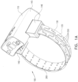
- Fig. 1A is a schematic illustration of a perspective view of a first side of a tracking device 100 and Fig. 1B is a schematic illustration of a perspective view of a second side of a tracking device 100, according to an exemplary embodiment of the disclosure.
- Tracking device 100 includes a communication interface 110 that may serve as a GPS tracking device and/or a transmitter/receiver that communicates with a base station or directly with a central server.
- the communication interface serves as a transceiver (transmitter/receiver) and in some embodiments the communication interface may serve only as a transmitter or only as a receiver.
- the tracking device 100 also includes a flexible strap 120 that is configured to securely couple the communication interface 110 to a limb of a person, for example an ankle or wrist.
- the strap 120 may be provided in the form of a strap 220 (e.g. Fig. 2B ) that is made up from a single elongated flexible thin sheet 260 of a strong material (e.g. stainless steel or strong plastic) coupled to links 250 guiding a fiber optic cable 130 between the links 250.
- the strap 120 is designed to serve as a reusable robust flexible strap 120 that cannot be cut with household tools or optionally even with a bolt cutter or wire cutter.
- the strap 120 may be provided in the form of a strap 320 (e.g. Fig.
- the links (250, 350) are thicker than the thin sheets (260, 360).
- the communication interface 110 of the tracking device 100 identifies its location and communicates the identified location to the central server to enable monitoring the location of the person wearing the tracking device 100.
- the tracking device 100 also monitors that it is coupled to the person's limb and has not been tampered with or removed.
- the fiber optic cable 130 embedded within the strap 120 is used to monitor and detect tampering.
- the fiber optic cable 130 serves to transmit a light signal from the first side of the communication interface 110 to the second side to verify that the strap 120 is intact, has not been tampered with and remains securely locked around the person's limb.
- Fig. 1C is a schematic illustration of a side view of tracking device 100
- Fig. 1D is a schematic illustration of a front view of tracking device 100
- Fig. 1E is a schematic illustration of an upper view of tracking device 100, according to an exemplary embodiment of the disclosure.
- the straps 120 are premanufactured in various sizes and not cut to size and prepared on the spot to fit a specific person.
- the straps 120 are color coded to designate the size of the strap 120.
- the installer arrives with a set of straps 120 and selects a correct sized strap 120 to fit the limb of the person that the tracking device 100 is being attached to.
- removing the strap 120 it may be cleaned and restocked for future use on a different person.
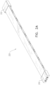
- Fig. 2A is a schematic illustration of strap 220
- Fig. 2B is a schematic illustration of an exploded view of strap 220
- Fig. 2C is a schematic illustration of a perspective back view of strap 220, according to an exemplary embodiment of the disclosure.
- communication interface 110 is enclosed in an enclosure 145 and includes on each side a receptacle 140 to grasp the strap 220.
- Each end of the strap 220 is fit with a head 210 that is configured to lock an end of strap 220 into one of the receptacles 140.
- each head 210 includes an interface 225 for connecting with the ends of fiber optic cable 130.
- interface 225 is configured to connect with an optical circuit within the enclosure of communication interface 110 and form an optical connection between the sides of the tracking device 100.
- the interface 225 is attached with screws 270 to head 210 and coupled to sheet 260 in a similar manner as the links 250.
- each head 210 may include a latch 230 that is configured to make head 210 snap into the receptacle 140, locking the head 210 in place and preventing it from sliding back out.
- a special tool is required to press on latch 230 and release strap 220 from receptacle 140.
- the links 250 are coupled to the thin sheet 260, for example using an adhesive, screws or by welding (e.g. laser welding).
- the links 250 are arranged in two rows along the elongated axis of sheet 260, leaving a channel 235 for placing fiber optic cable 130 between the links 250 above sheet 260. Accordingly, the links 250 provide strength to strap 220 and protect fiber optic 130, while maintaining flexibility.
- strap 220 is covered by a protective cover 290.
- the cover is made from a flexible material such as silicon, rubber, plastic and/or other materials e.g. biocompatible materials.
- the cover 290 covers a single side of strap 220, for example the outer circumference of the strap 220 when attached to communication interface 110.
- protective cover 290 may cover strap 220 on two sides, for example the outer circumference and inner circumference of strap 220, or completely enclose the strap 220 along the length of the strap 220.
- Fig. 3A is a schematic illustration of an alternative strap 320
- Fig. 3B is a schematic illustration of alternative strap 320 with cut out portions
- Fig. 3C is a schematic illustration of alternative strap 320 with a protective coating 390, according to an exemplary embodiment of the disclosure.
- Strap 320 is similar to strap 220. Both include a head (310, 210) with a latch (330, 230), screws (370, 270) and an interface (325, 225) for locking the strap (320, 220) in receivers 140.
- strap 320 comprises links 350 in the form of single interlinking elements each covering the entire width of the strap 320.
- strap 320 comprises multiple sheets 360 that cover the entire length of the strap 320 and are held together by being coupled to the links 350.
- the fiber optic cable 130 is positioned under the links 350 between the multiple sheets along the inner circumference of strap 320 to reduce stress on the fiber optic cable 130.
- the links 350 may be attached along the inner circumference of the strap 320 and the sheets 360 along the outer circumference of strap 320, with fiber optic cable 130 positioned along the outer circumference.
- the sheet 260 covers the entire width of the strap 220 and the links 250 are coupled to the sheet leaving a channel 235 for placing the fiber optic cable 130 between the links 250.
- the links 250 are placed next to each other to cover the entire length of the strap 220.
- the links (350, 250) are not directly connected together but rather only positioned next to each other (e.g. in an interlocking pattern) and coupled to the sheets (360, 260) to form a robust flexible strap (320, 220) that can be bent to fit around the person's limb.
- links 350 include protection tabs 375 that extend downward from the links 350 (toward the inner circumference) to form a protected channel for the fiber optic cable 130 between the multiple sheets 360.
- head 310 includes interface 325, thus head 310 is connected directly to sheet 360 instead of indirectly via interface 325.
- the sheets (260, 360) and links (250, 350) are made from stainless steel.
- they may be made from other materials, for example metals or plastics (e.g. polycarbonate).
- the materials may be rigid and lightweight so that the tracking device 100 is less of a burden on the person to which it is attached.
Landscapes
- Business, Economics & Management (AREA)
- Emergency Management (AREA)
- Physics & Mathematics (AREA)
- General Physics & Mathematics (AREA)
- Health & Medical Sciences (AREA)
- Child & Adolescent Psychology (AREA)
- General Health & Medical Sciences (AREA)
- Engineering & Computer Science (AREA)
- Computer Networks & Wireless Communication (AREA)
- Purses, Travelling Bags, Baskets, Or Suitcases (AREA)
Description
- It is common practice today to attach a body worn tracking device to a person for monitoring their location and/or enforcing a location based policy such as house arrest, curfew sentencing, pre-trial sentencing, parole and probation. Typically the tracking device is attached with a strap to the ankle of the person or to other limbs, for example the wrist of the person. The person is prohibited from removing the tracking device to prevent them from violating the location based policy.
- Typically the strap is designed to serve as a security strap, which is designed to make it physically hard for the person to remove the strap and/or includes tamper detection means that identify removal of the strap. Optionally, the detection means might even detect attempts to remove the strap. The tamper detection may be implemented by including a wire or fiber optic cable to close a circuit. Optionally, the wire or fiber optic cable surrounds the person's limb and is monitored by the tracking device. If the wire or fiber optic cable is cut or broken the tracking device will identify a violation and provide notification.
- Likewise it is desirable that the security strap be robust so that the security strap will not be accidently broken, easily removed when desired, with standard household utensils or easily removed in an act of rage or moment of insanity. However, on the other hand comfort considerations make it desirable that the strap be lightweight and flexible and not a solid rigid band.
- Thus it is desirable to form a flexible strap, with tamper means, that is not easily damaged or removed.
-
WO 2016/164994 A1 describes an optical coupling system with a mechanical seal, the features of which provide a coupling system with a specific mechanical structure to keep the components of a product locked together in an inviolable manner, and is based on the integration of an optical security system formed by an optical fibre cable and lenses with a mechanical security device formed by a strap, a holder, a sleeve and a lock, in order to optimize totally and carry out with high security coupling, locking and inviolability-ensuring processes of product components in an extremely convenient, accurate and ergonomic manner, besides transmitting signals warning when the components are violated, providing complete impermeability of the coupling of optical fibre with the lens against water, dust and dirt, on the basis of a highly resistant, secure and versatile coupling system. -
US 2011/248853 A1 relates to a mounting strap assembly of a tracking device includes a primary mounting strap and one more secondary reinforcing support straps. Continuity sensing elements and other tamper detection means detect any attempt to cut through the mounting strap assembly during an attempted removal of the tracking device from an offender or other mounted location. The reinforcing support straps keep the mounting strap assembly from being completely severed while providing authorities time to be summoned to the location where the tracking device is located and prior to the tracking device being completely removed. -
EP 3 382 664 A1 relates to a buckle for a monitoring device attached to a person to be monitored (e.g. elderly people, offenders), provided with a male connecting member and a female connecting member, with the female connecting member containing at least one wedge-shaped locking element, and the male connecting member comprising at least one flexible latching element for engaging with the locking element. A flange on the male connecting member seals off the mechanism in the locked state, so that the latching element cannot be released. The buckle can be opened only by using a sharp-tipped tool which perforates a thinner-walled spot on the flange, positioned to correspond with a channel in the locking elements. Perforation makes tampering visible. The tool can then enter the space between the latching element and the side wall of the female connecting member via the channel, opening the buckle by tilting the latch away from the female connecting member. - An aspect of an embodiment of the disclosure relates to a device and method for attaching a tracking device to a person's limb. The device includes a communication interface for communicating with a server and a strap to attach the communication interface to a person's limb. The strap is designed to be detachable so that it can be reused. The device also includes a fiber optic cable to detect tampering. The strap is designed to be robust so that it cannot be easily cut, for example with home utensils or even with a bolt cutter or wire cutter. The strap includes one or more thin elongated flexible sheets with a plurality of interlocking links coupled to one side of the sheets to form a protected channel to accommodate the fiber optic cable. The links enhance robustness of the strap, protecting the strap from being cut, and the links preserve flexibility of the strap.
- According to a first realisation of the invention, , the strap includes a single sheet with interlocking links coupled to one side of the sheet. Wherein the links are arranged in two columns to form a channel for positioning the fiber optic cable. According to a second realisation of the invention, the strap includes two or more sheets and links coupled to one side of the sheets holding the sheets in position. Optionally, the links extend across the width of the strap and form an interlocking pattern from one end of the strap to the other. Optionally, the fiber optic cable is positioned beneath the links between the two or more sheets. In some embodiments of the disclosure, the links include tabs that extend downward to form a protected channel between the sheets to position the fiber optic cable.
- In some embodiments of the disclosure, the links are covered by a protective cover, for example a rubber, plastic or silicon cover to protect the links and sheets from dirt. The protective cover may be on a single side to cover the links, or on two sides, covering the links and the sheets. Alternatively, the protective cover may cover the entire body of the strap.
- There is thus provided according to an exemplary embodiment of the disclosure, a tracking device, comprising:
- A communication interface encased in a encasement with a receptacle on two opposite sides of the encasement;
- A strap, comprising:
- One or more thin elongated flexible sheets;
- Links coupled to one side of the one or more thin elongated flexible sheets;
- A fiber optic cable extending from a first end of the one or more thin elongated flexible sheets to a second end of the one or more thin elongated flexible sheets;
- A head connected to each end of the one or more thin elongated flexible sheets; wherein the heads are configured to fit into the receptacles and lock the strap in the receptacles thus preventing the strap from sliding out of the receptacles; and
- Wherein the communication interface is configured to detect tampering with the strap by transmitting an optical signal through the fiber optic cable.
- In a first variant of the invention the strap includes a single thin elongated flexible sheet and the links are arranged in two rows along an elongated axis on one side of the thin elongated flexible sheet, forming a channel between the two rows for placing the fiber optic cable between the links.
- In a second variant of the invention, the strap includes multiple thin elongated flexible sheets; wherein each link defines the width of the strap and is coupled to each of the multiple thin elongated flexible sheets; and wherein the links are interlocked along an elongated axis on one side of the multiple thin elongated flexible sheets. In an exemplary embodiment of the disclosure, the links include protection tabs that extend downward from the links toward the inner circumference of the strap to form a protected channel for the fiber optic cable between the multiple thin elongated flexible sheets. Optionally, the fiber optic cable is positioned below the links toward the inner circumference of the strap between the multiple thin elongated flexible sheets.
- In an exemplary embodiment of the disclosure, the strap further includes an interface connected at each end of the fiber optic cable; wherein the interface at each end is coupled to the ends of the one or more thin elongated flexible sheets and attached to a respective head. Optionally, the head at each end of the strap is coupled directly to the ends of the one or more thin elongated flexible sheets. In an exemplary embodiment of the disclosure, each head includes a latch that is configured to lock the head in the receptacle and wherein the latch is configured to also enable release of the head from the receptacle by pressing on the latch with a specially designed tool. Optionally, the links of the strap are covered by a protective cover. In an exemplary embodiment of the disclosure, the protective cover is color coded to designate a length of the strap.
- There is further provided according to an exemplary embodiment of the disclosure, a method of connecting a tracking device as illustrated above to a limb of a person. The claimed invention is defined by the independent claims.
- Particular embodiments are defined by the dependent claims.
- The present disclosure will be understood and better appreciated from the following detailed description taken in conjunction with the drawings. Identical structures, elements or parts, which appear in more than one figure, are generally labeled with the same or similar number in all the figures in which they appear, wherein:
-
Fig. 1A is a schematic illustration of a perspective view of a first side of a tracking device, according to an exemplary embodiment of the disclosure; -
Fig. 1B is a schematic illustration of a perspective view of a second side of a tracking device, according to an exemplary embodiment of the disclosure; -
Fig. 1C is a schematic illustration of a side view of a tracking device, according to an exemplary embodiment of the disclosure; -
Fig. 1D is a schematic illustration of a front view of a tracking device, according to an exemplary embodiment of the disclosure; -
Fig. 1E is a schematic illustration of an upper view of a tracking device, according to an exemplary embodiment of the disclosure; -
Fig. 2A is a schematic illustration of a strap, according to an exemplary embodiment of the disclosure; -
Fig. 2B is a schematic illustration of an exploded view of a strap, according to an exemplary embodiment of the disclosure; -
Fig. 2C is a schematic illustration of a perspective back view of a strap, according to an exemplary embodiment of the disclosure; -
Fig. 3A is a schematic illustration of an alternative strap, according to an exemplary embodiment of the disclosure; -
Fig. 3B is a schematic illustration of an alternative strap with cut out portions, according to an exemplary embodiment of the disclosure; and -
Fig. 3C is a schematic illustration of an alternative strap with a protective coating, according to an exemplary embodiment of the disclosure. -
Fig. 1A is a schematic illustration of a perspective view of a first side of atracking device 100 andFig. 1B is a schematic illustration of a perspective view of a second side of atracking device 100, according to an exemplary embodiment of the disclosure.Tracking device 100 includes acommunication interface 110 that may serve as a GPS tracking device and/or a transmitter/receiver that communicates with a base station or directly with a central server. In some embodiments of the disclosure, the communication interface serves as a transceiver (transmitter/receiver) and in some embodiments the communication interface may serve only as a transmitter or only as a receiver. - In an exemplary embodiment of the disclosure, the
tracking device 100 also includes aflexible strap 120 that is configured to securely couple thecommunication interface 110 to a limb of a person, for example an ankle or wrist. Optionally, thestrap 120 may be provided in the form of a strap 220 (e.g.Fig. 2B ) that is made up from a single elongated flexiblethin sheet 260 of a strong material (e.g. stainless steel or strong plastic) coupled tolinks 250 guiding afiber optic cable 130 between thelinks 250. Thestrap 120 is designed to serve as a reusable robustflexible strap 120 that cannot be cut with household tools or optionally even with a bolt cutter or wire cutter. Alternatively, thestrap 120 may be provided in the form of a strap 320 (e.g.Fig. 3B ) that is made up from two or more elongated thin sheets offlexible material 360 coupled tolinks 350 holding the sheets together and wherein thefiber optic cable 130 is positioned between thesheets 360 below thelinks 350. Optionally, the links (250, 350) are thicker than the thin sheets (260, 360). - In an exemplary embodiment of the disclosure, the
communication interface 110 of thetracking device 100 identifies its location and communicates the identified location to the central server to enable monitoring the location of the person wearing thetracking device 100. Thetracking device 100 also monitors that it is coupled to the person's limb and has not been tampered with or removed. According to the invention, thefiber optic cable 130 embedded within thestrap 120 is used to monitor and detect tampering. For example thefiber optic cable 130 serves to transmit a light signal from the first side of thecommunication interface 110 to the second side to verify that thestrap 120 is intact, has not been tampered with and remains securely locked around the person's limb. -
Fig. 1C is a schematic illustration of a side view oftracking device 100,Fig. 1D is a schematic illustration of a front view oftracking device 100 andFig. 1E is a schematic illustration of an upper view oftracking device 100, according to an exemplary embodiment of the disclosure. Optionally, thestraps 120 are premanufactured in various sizes and not cut to size and prepared on the spot to fit a specific person. In some embodiments of the disclosure, thestraps 120 are color coded to designate the size of thestrap 120. In an exemplary embodiment of the disclosure, when installing thestrap 120 the installer arrives with a set ofstraps 120 and selects a correctsized strap 120 to fit the limb of the person that thetracking device 100 is being attached to. Optionally, when removing thestrap 120 it may be cleaned and restocked for future use on a different person. -
Fig. 2A is a schematic illustration ofstrap 220,Fig. 2B is a schematic illustration of an exploded view ofstrap 220 andFig. 2C is a schematic illustration of a perspective back view ofstrap 220, according to an exemplary embodiment of the disclosure. According to the invention,communication interface 110 is enclosed in anenclosure 145 and includes on each side areceptacle 140 to grasp thestrap 220. Each end of thestrap 220 is fit with ahead 210 that is configured to lock an end ofstrap 220 into one of thereceptacles 140. In an exemplary embodiment of the disclosure, eachhead 210 includes aninterface 225 for connecting with the ends offiber optic cable 130. Optionally,interface 225 is configured to connect with an optical circuit within the enclosure ofcommunication interface 110 and form an optical connection between the sides of thetracking device 100. Optionally, theinterface 225 is attached withscrews 270 to head 210 and coupled tosheet 260 in a similar manner as thelinks 250. Additionally, eachhead 210 may include alatch 230 that is configured to makehead 210 snap into thereceptacle 140, locking thehead 210 in place and preventing it from sliding back out. Optionally, a special tool is required to press onlatch 230 andrelease strap 220 fromreceptacle 140. - In an exemplary embodiment of the disclosure, the
links 250 are coupled to thethin sheet 260, for example using an adhesive, screws or by welding (e.g. laser welding). In a first imiplementation of the invention, thelinks 250 are arranged in two rows along the elongated axis ofsheet 260, leaving achannel 235 for placingfiber optic cable 130 between thelinks 250 abovesheet 260. Accordingly, thelinks 250 provide strength to strap 220 and protectfiber optic 130, while maintaining flexibility. - In an exemplary embodiment of the disclosure,
strap 220 is covered by aprotective cover 290. The cover is made from a flexible material such as silicon, rubber, plastic and/or other materials e.g. biocompatible materials. In some embodiments of the disclosure, thecover 290 covers a single side ofstrap 220, for example the outer circumference of thestrap 220 when attached tocommunication interface 110. Alternatively,protective cover 290 may coverstrap 220 on two sides, for example the outer circumference and inner circumference ofstrap 220, or completely enclose thestrap 220 along the length of thestrap 220. -
Fig. 3A is a schematic illustration of analternative strap 320,Fig. 3B is a schematic illustration ofalternative strap 320 with cut out portions andFig. 3C is a schematic illustration ofalternative strap 320 with aprotective coating 390, according to an exemplary embodiment of the disclosure. -
Strap 320 is similar tostrap 220. Both include a head (310, 210) with a latch (330, 230), screws (370, 270) and an interface (325, 225) for locking the strap (320, 220) inreceivers 140. However as shown infigures 3A to 3C strap 320 compriseslinks 350 in the form of single interlinking elements each covering the entire width of thestrap 320. Likewisestrap 320 comprisesmultiple sheets 360 that cover the entire length of thestrap 320 and are held together by being coupled to thelinks 350. In an exemplary embodiment of the disclosure, thefiber optic cable 130 is positioned under thelinks 350 between the multiple sheets along the inner circumference ofstrap 320 to reduce stress on thefiber optic cable 130. Alternatively, thelinks 350 may be attached along the inner circumference of thestrap 320 and thesheets 360 along the outer circumference ofstrap 320, withfiber optic cable 130 positioned along the outer circumference. - In contrast to strap 320, in
strap 220 thesheet 260 covers the entire width of thestrap 220 and thelinks 250 are coupled to the sheet leaving achannel 235 for placing thefiber optic cable 130 between thelinks 250. Thelinks 250 are placed next to each other to cover the entire length of thestrap 220. - In an exemplary embodiment of the disclosure, the links (350, 250) are not directly connected together but rather only positioned next to each other (e.g. in an interlocking pattern) and coupled to the sheets (360, 260) to form a robust flexible strap (320, 220) that can be bent to fit around the person's limb.
- In an exemplary embodiment of the disclosure,
links 350 includeprotection tabs 375 that extend downward from the links 350 (toward the inner circumference) to form a protected channel for thefiber optic cable 130 between themultiple sheets 360. - In some embodiments of the disclosure,
head 310 includesinterface 325, thus head 310 is connected directly tosheet 360 instead of indirectly viainterface 325. - In some embodiments of the disclosure, the sheets (260, 360) and links (250, 350) are made from stainless steel. Alternatively, they may be made from other materials, for example metals or plastics (e.g. polycarbonate). Optionally, the materials may be rigid and lightweight so that the
tracking device 100 is less of a burden on the person to which it is attached. - It should be appreciated that the above described methods and apparatus may be varied in many ways, including omitting or adding steps, changing the order of steps and the type of devices used. It should be appreciated that different features may be combined in different ways. In particular, not all the features shown above in a particular embodiment are necessary in every embodiment of the disclosure. Further combinations of the above features are also considered to be within the scope of some embodiments of the disclosure. It will also be appreciated by persons skilled in the art that the present disclosure is not limited to what has been particularly shown and described hereinabove but rather will be defined by the claims.
Claims (15)
- A tracking device (100), comprising:a communication interface (110) encased in an encasement (145) with a receptacle (140) on two opposite sides of the encasement (145);a strap (220), comprising:a single thin elongated flexible sheet (260);interlocking links (250) coupled to one side of the single thin elongated flexible sheets (260);a fiber optic cable (130) extending from a first end of the one or more thin elongated flexible sheets (260) to a second end of the one or more thin elongated flexible sheets (260);a head (210) connected to each end of the one or more thin elongated flexible sheets (260); wherein the heads (210) are configured to fit into the receptacles (140) and lock the strap (220) in the receptacles (140) thus preventing the strap (220) from sliding out of the receptacles (140);wherein the communication interface (110) is configured to detect tampering with the strap (220) by transmitting an optical signal through the fiber optic cable (130);and wherein the links (250) are arranged in two rows along an elongated axis on one side of the thin elongated flexible sheet (260), forming a channel (235) between the two rows for placing the fiber optic cable (130) between the links (250).
- The device (100) according to claim 1, wherein the strap (220) further includes an interface (225) connected at each end of the fiber optic cable (130); wherein the interface (225) at each end is coupled to the ends of the one or more thin elongated flexible sheets (260) and attached to a respective head (210).
- The device (100) according to claim 1, wherein the head (210) at each end of the strap (220) is coupled directly to the ends of the one or more thin elongated flexible sheets (260).
- The device (100) according to claim 1, wherein each head (210) includes a latch (230) that is configured to lock the head (210) in the receptacle and wherein the latch (230) is configured to also enable release of the head (210) from the receptacle (140) by pressing on the latch (230) with a specially designed tool.
- The device (100) according to claim 1, wherein the links (250) of the strap (220) are covered by a protective cover (290).
- The device according to claim 5, wherein the protective cover (290) is color coded to designate a length of the strap (220).
- A tracking device (100), comprising:a communication interface (110) encased in an encasement (145) with a receptacle (140) on two opposite sides of the encasement (145);a strap (320), comprising:multiple thin elongated flexible sheets (360);interlocking links (350) coupled to one side of the multiple thin elongated flexible sheets (260);a fiber optic cable (130) extending from a first end of the one or more thin elongated flexible sheets (360) to a second end of the one or more thin elongated flexible sheets (360);a head (310) connected to each end of the one or more thin elongated flexible sheets (360); wherein the heads (310) are configured to fit into the receptacles (140) and lock the strap (320) in the receptacles (140) thus preventing the strap (320) from sliding out of the receptacles (140);wherein the communication interface (110) is configured to detect tampering with the strap (320) by transmitting an optical signal through the fiber optic cable (130); andwherein each link (350) defines the width of the strap (320) and is coupled to each of the multiple thin elongated flexible sheets (360); and wherein the links (350) are interlocked along an elongated axis on one side of the multiple thin elongated flexible sheets (360).
- The device (100) according to claim 7, wherein the links (350) include protection tabs (375) that extend downward from the links (350) toward the inner circumference of the strap (320) to form a protected channel for the fiber optic cable between the multiple thin elongated flexible sheets.
- The device (100) according to claim 7, wherein the fiber optic cable (130) is positioned below the links (350) toward the inner circumference of the strap (320) between the multiple thin elongated flexible sheets (360).
- A method of connecting a tracking device (100) to a limb of a person, comprising:receiving a communication interface (110) encased in an encasement (145) with a receptacle (140) on two opposite sides of the encasement (145);receiving a strap (220), comprising:a single thin elongated flexible sheet (260);interlocking links (250) coupled to one side of the thin elongated flexible sheets (260);a fiber optic cable (130) extending from a first end of the thin elongated flexible sheets (260) to a second end of the thin elongated flexible sheets (260);a head (210) connected to each end of the thin elongated flexible sheets (260);inserting the heads (210) of the strap (220) into the receptacles (140) of the communication interface (110) to lock the straps (220) to the communication interface (110) and prevent the straps (220) from sliding out of the receptacles (140); wherein the communication interface (110) is configured to detect tampering with the strap (220) by transmitting an optical signal through the fiber optic cable (130); andwherein the links (250) are arranged in two rows along an elongated axis of the thin elongated flexible sheet (260), forming a channel (235) between the two rows for placing the fiber optic cable (130) between the links (250).
- The method according to claim 10, wherein the strap (220) further includes an interface (225) connected at each end of the fiber optic cable (130); wherein the interface (225) at each end is coupled to the ends of the multiple thin elongated sheets (260) and attached to a respective head (210).
- The method according to claim 10, wherein the head (210) at each end of the strap (220) is coupled directly to the ends of the multiple thin elongated sheets (260).
- A method of connecting a tracking device (100) to a limb of a person, comprising:receiving a communication interface (110) encased in a encasement (145) with a receptacle (140) on two opposite sides of the encasement (145);receiving a strap (320), comprising:multiple thin elongated flexible sheets (360);interlocking links (350) coupled to one side of the multiple thin elongated flexible sheets (360);a fiber optic cable (130) extending from a first end of the thin elongated flexible sheets (360) to a second end of the thin elongated flexible sheets (360);a head (310) connected to each end of the thin elongated flexible sheets (360);inserting the heads (310) of the strap (220) into the receptacles (140) of the communication interface (110) to lock the straps (320) to the communication interface (110) and prevent the straps (320) from sliding out of the receptacles (140);wherein the communication interface (110) is configured to detect tampering with the strap (320) by transmitting an optical signal through the fiber optic cable (130); andwherein each link (350) defines the width of the strap (320) and is coupled to each of the multiple thin elongated flexible sheets (360); and wherein the links (350) are interlocked along an elongated axis on one side of the multiple thin elongated flexible sheets (360).
- The method according to claim 13, wherein the links (350) include protection tabs (375) that extend downward from the links (350) toward the inner circumference of the strap (320) to form a protected channel for the fiber optic cable (130) between the multiple thin elongated flexible sheets (360).
- The method according to claim 13, wherein the fiber optic cable (130) is positioned below the links (350) toward the inner circumference of the strap (320) between the multiple thin elongated sheets (360).
Applications Claiming Priority (2)
| Application Number | Priority Date | Filing Date | Title |
|---|---|---|---|
| US201962810512P | 2019-02-26 | 2019-02-26 | |
| PCT/IL2020/050220 WO2020174474A1 (en) | 2019-02-26 | 2020-02-26 | Protected security strap |
Publications (3)
| Publication Number | Publication Date |
|---|---|
| EP3746997A1 EP3746997A1 (en) | 2020-12-09 |
| EP3746997A4 EP3746997A4 (en) | 2021-12-01 |
| EP3746997B1 true EP3746997B1 (en) | 2024-05-29 |
Family
ID=72239485
Family Applications (1)
| Application Number | Title | Priority Date | Filing Date |
|---|---|---|---|
| EP20760355.6A Active EP3746997B1 (en) | 2019-02-26 | 2020-02-26 | Protected security strap |
Country Status (5)
| Country | Link |
|---|---|
| US (1) | US11455878B2 (en) |
| EP (1) | EP3746997B1 (en) |
| AU (1) | AU2020223651B2 (en) |
| ES (1) | ES2990188T3 (en) |
| WO (1) | WO2020174474A1 (en) |
Families Citing this family (3)
| Publication number | Priority date | Publication date | Assignee | Title |
|---|---|---|---|---|
| CN210726884U (en) * | 2019-06-25 | 2020-06-12 | Oppo广东移动通信有限公司 | Watch straps, watch strap assemblies and wearable devices |
| ES3013620T3 (en) * | 2019-07-08 | 2025-04-14 | Attenti Electronic Monitoring Ltd | Adjustable electronic monitoring device |
| CN114145547B (en) * | 2021-12-31 | 2024-02-02 | 深圳市新隆达表业有限公司 | A rubber-covered watch chain, watch-chain rubber-covering equipment and watch-chain rubber-covering process |
Family Cites Families (9)
| Publication number | Priority date | Publication date | Assignee | Title |
|---|---|---|---|---|
| US5471197A (en) | 1993-02-19 | 1995-11-28 | Cincinnati Microwave, Inc. | Tamper-proof bracelet for home arrest system |
| US20030174059A1 (en) | 2002-03-12 | 2003-09-18 | Michael Reeves | Home detention system |
| US7612678B1 (en) | 2005-08-01 | 2009-11-03 | Guidance Monitoring Limited | Monitoring tags |
| US7382268B2 (en) * | 2006-06-13 | 2008-06-03 | Hartman Kevin L | Device and method for tethering a person wirelessly with a cellular telephone |
| US8514070B2 (en) * | 2010-04-07 | 2013-08-20 | Securealert, Inc. | Tracking device incorporating enhanced security mounting strap |
| GB2501909A (en) | 2012-05-10 | 2013-11-13 | Richard Satherley | Flexible strap |
| WO2016131415A1 (en) * | 2015-02-17 | 2016-08-25 | Webbem Limited | Device for carrying cordage and survival tools and method for manufacturing the same |
| BR102015008709A2 (en) | 2015-04-17 | 2016-12-06 | Spacecomm Monitoramento S A | mechanical seal optical coupling system |
| PL3382664T3 (en) | 2017-03-27 | 2020-07-27 | Ebs Sp. Z O.O. | Buckle for electronic surveillance device and method of opening the same |
-
2020
- 2020-02-26 AU AU2020223651A patent/AU2020223651B2/en active Active
- 2020-02-26 WO PCT/IL2020/050220 patent/WO2020174474A1/en not_active Ceased
- 2020-02-26 US US16/975,127 patent/US11455878B2/en active Active
- 2020-02-26 ES ES20760355T patent/ES2990188T3/en active Active
- 2020-02-26 EP EP20760355.6A patent/EP3746997B1/en active Active
Also Published As
| Publication number | Publication date |
|---|---|
| EP3746997A4 (en) | 2021-12-01 |
| AU2020223651B2 (en) | 2021-09-09 |
| AU2020223651A1 (en) | 2020-09-17 |
| ES2990188T3 (en) | 2024-11-29 |
| EP3746997A1 (en) | 2020-12-09 |
| US11455878B2 (en) | 2022-09-27 |
| WO2020174474A1 (en) | 2020-09-03 |
| US20210201650A1 (en) | 2021-07-01 |
| NZ767422A (en) | 2022-03-25 |
Similar Documents
| Publication | Publication Date | Title |
|---|---|---|
| AU2020223651B2 (en) | Protected security strap | |
| EP1177546B1 (en) | Tagging device | |
| US5497149A (en) | Global security system | |
| US7872588B2 (en) | Monitoring tags | |
| US9315973B2 (en) | Fire hydrant cover including a controller coupled with a transceiver and a lock mechanism | |
| US6388612B1 (en) | Global cellular position tracking device | |
| CA2261652C (en) | Portable tracking apparatus for continuous position determination of criminal offenders and victims | |
| US20100267361A1 (en) | Monitoring device and system | |
| US8115621B2 (en) | Device for tracking the movement of individuals or objects | |
| US7864059B2 (en) | Portable tracking alarm apparatus | |
| EP3382664B1 (en) | Buckle for electronic surveillance device and method of opening the same | |
| US11308748B2 (en) | Flexible identification band with cut detection | |
| JP7261470B2 (en) | Safety belt hook locking state detector | |
| NZ767422B2 (en) | Protected Security Strap | |
| EP3997680B1 (en) | Adjustable electronic monitoring device | |
| AU2009201910A1 (en) | Protective Shroud | |
| EP2948381B1 (en) | Apparatus for cutting electronic monitoring bracelet straps | |
| US20250292670A1 (en) | Remote monitoring system and method for controlled population | |
| JP7604940B2 (en) | Disaster prevention equipment | |
| JP4825437B2 (en) | Surveillance belt | |
| HUP9800440A1 (en) | Method for detecting accidental or intentional operation trouble of a wireless telemonitoring system |
Legal Events
| Date | Code | Title | Description |
|---|---|---|---|
| STAA | Information on the status of an ep patent application or granted ep patent |
Free format text: STATUS: UNKNOWN |
|
| STAA | Information on the status of an ep patent application or granted ep patent |
Free format text: STATUS: THE INTERNATIONAL PUBLICATION HAS BEEN MADE |
|
| PUAI | Public reference made under article 153(3) epc to a published international application that has entered the european phase |
Free format text: ORIGINAL CODE: 0009012 |
|
| STAA | Information on the status of an ep patent application or granted ep patent |
Free format text: STATUS: REQUEST FOR EXAMINATION WAS MADE |
|
| 17P | Request for examination filed |
Effective date: 20200831 |
|
| AK | Designated contracting states |
Kind code of ref document: A1 Designated state(s): AL AT BE BG CH CY CZ DE DK EE ES FI FR GB GR HR HU IE IS IT LI LT LU LV MC MK MT NL NO PL PT RO RS SE SI SK SM TR |
|
| AX | Request for extension of the european patent |
Extension state: BA ME |
|
| A4 | Supplementary search report drawn up and despatched |
Effective date: 20211102 |
|
| RIC1 | Information provided on ipc code assigned before grant |
Ipc: A44C 5/02 20060101ALI20211026BHEP Ipc: G08B 25/01 20060101ALI20211026BHEP Ipc: G08B 21/02 20060101ALI20211026BHEP Ipc: A44C 5/00 20060101ALI20211026BHEP Ipc: G08B 21/22 20060101ALI20211026BHEP Ipc: G08B 25/10 20060101AFI20211026BHEP |
|
| DAV | Request for validation of the european patent (deleted) | ||
| DAX | Request for extension of the european patent (deleted) | ||
| GRAP | Despatch of communication of intention to grant a patent |
Free format text: ORIGINAL CODE: EPIDOSNIGR1 |
|
| STAA | Information on the status of an ep patent application or granted ep patent |
Free format text: STATUS: GRANT OF PATENT IS INTENDED |
|
| INTG | Intention to grant announced |
Effective date: 20231219 |
|
| GRAS | Grant fee paid |
Free format text: ORIGINAL CODE: EPIDOSNIGR3 |
|
| GRAA | (expected) grant |
Free format text: ORIGINAL CODE: 0009210 |
|
| STAA | Information on the status of an ep patent application or granted ep patent |
Free format text: STATUS: THE PATENT HAS BEEN GRANTED |
|
| AK | Designated contracting states |
Kind code of ref document: B1 Designated state(s): AL AT BE BG CH CY CZ DE DK EE ES FI FR GB GR HR HU IE IS IT LI LT LU LV MC MK MT NL NO PL PT RO RS SE SI SK SM TR |
|
| REG | Reference to a national code |
Ref country code: CH Ref legal event code: EP |
|
| REG | Reference to a national code |
Ref country code: IE Ref legal event code: FG4D |
|
| REG | Reference to a national code |
Ref country code: DE Ref legal event code: R096 Ref document number: 602020031675 Country of ref document: DE |
|
| REG | Reference to a national code |
Ref country code: NL Ref legal event code: FP |
|
| REG | Reference to a national code |
Ref country code: LT Ref legal event code: MG9D |
|
| PG25 | Lapsed in a contracting state [announced via postgrant information from national office to epo] |
Ref country code: IS Free format text: LAPSE BECAUSE OF FAILURE TO SUBMIT A TRANSLATION OF THE DESCRIPTION OR TO PAY THE FEE WITHIN THE PRESCRIBED TIME-LIMIT Effective date: 20240929 |
|
| PG25 | Lapsed in a contracting state [announced via postgrant information from national office to epo] |
Ref country code: BG Free format text: LAPSE BECAUSE OF FAILURE TO SUBMIT A TRANSLATION OF THE DESCRIPTION OR TO PAY THE FEE WITHIN THE PRESCRIBED TIME-LIMIT Effective date: 20240529 |
|
| PG25 | Lapsed in a contracting state [announced via postgrant information from national office to epo] |
Ref country code: HR Free format text: LAPSE BECAUSE OF FAILURE TO SUBMIT A TRANSLATION OF THE DESCRIPTION OR TO PAY THE FEE WITHIN THE PRESCRIBED TIME-LIMIT Effective date: 20240529 Ref country code: FI Free format text: LAPSE BECAUSE OF FAILURE TO SUBMIT A TRANSLATION OF THE DESCRIPTION OR TO PAY THE FEE WITHIN THE PRESCRIBED TIME-LIMIT Effective date: 20240529 |
|
| PG25 | Lapsed in a contracting state [announced via postgrant information from national office to epo] |
Ref country code: GR Free format text: LAPSE BECAUSE OF FAILURE TO SUBMIT A TRANSLATION OF THE DESCRIPTION OR TO PAY THE FEE WITHIN THE PRESCRIBED TIME-LIMIT Effective date: 20240830 |
|
| REG | Reference to a national code |
Ref country code: AT Ref legal event code: MK05 Ref document number: 1691313 Country of ref document: AT Kind code of ref document: T Effective date: 20240529 |
|
| PG25 | Lapsed in a contracting state [announced via postgrant information from national office to epo] |
Ref country code: AT Free format text: LAPSE BECAUSE OF FAILURE TO SUBMIT A TRANSLATION OF THE DESCRIPTION OR TO PAY THE FEE WITHIN THE PRESCRIBED TIME-LIMIT Effective date: 20240529 |
|
| PG25 | Lapsed in a contracting state [announced via postgrant information from national office to epo] |
Ref country code: PL Free format text: LAPSE BECAUSE OF FAILURE TO SUBMIT A TRANSLATION OF THE DESCRIPTION OR TO PAY THE FEE WITHIN THE PRESCRIBED TIME-LIMIT Effective date: 20240529 |
|
| PG25 | Lapsed in a contracting state [announced via postgrant information from national office to epo] |
Ref country code: LV Free format text: LAPSE BECAUSE OF FAILURE TO SUBMIT A TRANSLATION OF THE DESCRIPTION OR TO PAY THE FEE WITHIN THE PRESCRIBED TIME-LIMIT Effective date: 20240529 |
|
| PG25 | Lapsed in a contracting state [announced via postgrant information from national office to epo] |
Ref country code: PL Free format text: LAPSE BECAUSE OF FAILURE TO SUBMIT A TRANSLATION OF THE DESCRIPTION OR TO PAY THE FEE WITHIN THE PRESCRIBED TIME-LIMIT Effective date: 20240529 Ref country code: NO Free format text: LAPSE BECAUSE OF FAILURE TO SUBMIT A TRANSLATION OF THE DESCRIPTION OR TO PAY THE FEE WITHIN THE PRESCRIBED TIME-LIMIT Effective date: 20240829 Ref country code: LV Free format text: LAPSE BECAUSE OF FAILURE TO SUBMIT A TRANSLATION OF THE DESCRIPTION OR TO PAY THE FEE WITHIN THE PRESCRIBED TIME-LIMIT Effective date: 20240529 Ref country code: IS Free format text: LAPSE BECAUSE OF FAILURE TO SUBMIT A TRANSLATION OF THE DESCRIPTION OR TO PAY THE FEE WITHIN THE PRESCRIBED TIME-LIMIT Effective date: 20240929 Ref country code: HR Free format text: LAPSE BECAUSE OF FAILURE TO SUBMIT A TRANSLATION OF THE DESCRIPTION OR TO PAY THE FEE WITHIN THE PRESCRIBED TIME-LIMIT Effective date: 20240529 Ref country code: GR Free format text: LAPSE BECAUSE OF FAILURE TO SUBMIT A TRANSLATION OF THE DESCRIPTION OR TO PAY THE FEE WITHIN THE PRESCRIBED TIME-LIMIT Effective date: 20240830 Ref country code: FI Free format text: LAPSE BECAUSE OF FAILURE TO SUBMIT A TRANSLATION OF THE DESCRIPTION OR TO PAY THE FEE WITHIN THE PRESCRIBED TIME-LIMIT Effective date: 20240529 Ref country code: BG Free format text: LAPSE BECAUSE OF FAILURE TO SUBMIT A TRANSLATION OF THE DESCRIPTION OR TO PAY THE FEE WITHIN THE PRESCRIBED TIME-LIMIT Effective date: 20240529 Ref country code: AT Free format text: LAPSE BECAUSE OF FAILURE TO SUBMIT A TRANSLATION OF THE DESCRIPTION OR TO PAY THE FEE WITHIN THE PRESCRIBED TIME-LIMIT Effective date: 20240529 Ref country code: RS Free format text: LAPSE BECAUSE OF FAILURE TO SUBMIT A TRANSLATION OF THE DESCRIPTION OR TO PAY THE FEE WITHIN THE PRESCRIBED TIME-LIMIT Effective date: 20240829 |
|
| REG | Reference to a national code |
Ref country code: ES Ref legal event code: FG2A Ref document number: 2990188 Country of ref document: ES Kind code of ref document: T3 Effective date: 20241129 |
|
| PG25 | Lapsed in a contracting state [announced via postgrant information from national office to epo] |
Ref country code: DK Free format text: LAPSE BECAUSE OF FAILURE TO SUBMIT A TRANSLATION OF THE DESCRIPTION OR TO PAY THE FEE WITHIN THE PRESCRIBED TIME-LIMIT Effective date: 20240529 |
|
| PG25 | Lapsed in a contracting state [announced via postgrant information from national office to epo] |
Ref country code: EE Free format text: LAPSE BECAUSE OF FAILURE TO SUBMIT A TRANSLATION OF THE DESCRIPTION OR TO PAY THE FEE WITHIN THE PRESCRIBED TIME-LIMIT Effective date: 20240529 |
|
| PG25 | Lapsed in a contracting state [announced via postgrant information from national office to epo] |
Ref country code: CZ Free format text: LAPSE BECAUSE OF FAILURE TO SUBMIT A TRANSLATION OF THE DESCRIPTION OR TO PAY THE FEE WITHIN THE PRESCRIBED TIME-LIMIT Effective date: 20240529 |
|
| PG25 | Lapsed in a contracting state [announced via postgrant information from national office to epo] |
Ref country code: SK Free format text: LAPSE BECAUSE OF FAILURE TO SUBMIT A TRANSLATION OF THE DESCRIPTION OR TO PAY THE FEE WITHIN THE PRESCRIBED TIME-LIMIT Effective date: 20240529 Ref country code: RO Free format text: LAPSE BECAUSE OF FAILURE TO SUBMIT A TRANSLATION OF THE DESCRIPTION OR TO PAY THE FEE WITHIN THE PRESCRIBED TIME-LIMIT Effective date: 20240529 |
|
| PG25 | Lapsed in a contracting state [announced via postgrant information from national office to epo] |
Ref country code: SM Free format text: LAPSE BECAUSE OF FAILURE TO SUBMIT A TRANSLATION OF THE DESCRIPTION OR TO PAY THE FEE WITHIN THE PRESCRIBED TIME-LIMIT Effective date: 20240529 |
|
| PG25 | Lapsed in a contracting state [announced via postgrant information from national office to epo] |
Ref country code: SM Free format text: LAPSE BECAUSE OF FAILURE TO SUBMIT A TRANSLATION OF THE DESCRIPTION OR TO PAY THE FEE WITHIN THE PRESCRIBED TIME-LIMIT Effective date: 20240529 Ref country code: SK Free format text: LAPSE BECAUSE OF FAILURE TO SUBMIT A TRANSLATION OF THE DESCRIPTION OR TO PAY THE FEE WITHIN THE PRESCRIBED TIME-LIMIT Effective date: 20240529 Ref country code: RO Free format text: LAPSE BECAUSE OF FAILURE TO SUBMIT A TRANSLATION OF THE DESCRIPTION OR TO PAY THE FEE WITHIN THE PRESCRIBED TIME-LIMIT Effective date: 20240529 Ref country code: EE Free format text: LAPSE BECAUSE OF FAILURE TO SUBMIT A TRANSLATION OF THE DESCRIPTION OR TO PAY THE FEE WITHIN THE PRESCRIBED TIME-LIMIT Effective date: 20240529 Ref country code: DK Free format text: LAPSE BECAUSE OF FAILURE TO SUBMIT A TRANSLATION OF THE DESCRIPTION OR TO PAY THE FEE WITHIN THE PRESCRIBED TIME-LIMIT Effective date: 20240529 Ref country code: CZ Free format text: LAPSE BECAUSE OF FAILURE TO SUBMIT A TRANSLATION OF THE DESCRIPTION OR TO PAY THE FEE WITHIN THE PRESCRIBED TIME-LIMIT Effective date: 20240529 |
|
| PG25 | Lapsed in a contracting state [announced via postgrant information from national office to epo] |
Ref country code: IT Free format text: LAPSE BECAUSE OF FAILURE TO SUBMIT A TRANSLATION OF THE DESCRIPTION OR TO PAY THE FEE WITHIN THE PRESCRIBED TIME-LIMIT Effective date: 20240529 |
|
| REG | Reference to a national code |
Ref country code: DE Ref legal event code: R097 Ref document number: 602020031675 Country of ref document: DE |
|
| PLBE | No opposition filed within time limit |
Free format text: ORIGINAL CODE: 0009261 |
|
| STAA | Information on the status of an ep patent application or granted ep patent |
Free format text: STATUS: NO OPPOSITION FILED WITHIN TIME LIMIT |
|
| PG25 | Lapsed in a contracting state [announced via postgrant information from national office to epo] |
Ref country code: SI Free format text: LAPSE BECAUSE OF FAILURE TO SUBMIT A TRANSLATION OF THE DESCRIPTION OR TO PAY THE FEE WITHIN THE PRESCRIBED TIME-LIMIT Effective date: 20240529 |
|
| 26N | No opposition filed |
Effective date: 20250303 |
|
| PGFP | Annual fee paid to national office [announced via postgrant information from national office to epo] |
Ref country code: ES Payment date: 20250331 Year of fee payment: 6 |
|
| PG25 | Lapsed in a contracting state [announced via postgrant information from national office to epo] |
Ref country code: SE Free format text: LAPSE BECAUSE OF FAILURE TO SUBMIT A TRANSLATION OF THE DESCRIPTION OR TO PAY THE FEE WITHIN THE PRESCRIBED TIME-LIMIT Effective date: 20240529 |
|
| PG25 | Lapsed in a contracting state [announced via postgrant information from national office to epo] |
Ref country code: MC Free format text: LAPSE BECAUSE OF FAILURE TO SUBMIT A TRANSLATION OF THE DESCRIPTION OR TO PAY THE FEE WITHIN THE PRESCRIBED TIME-LIMIT Effective date: 20240529 |
|
| REG | Reference to a national code |
Ref country code: CH Ref legal event code: PL |
|
| PG25 | Lapsed in a contracting state [announced via postgrant information from national office to epo] |
Ref country code: LU Free format text: LAPSE BECAUSE OF NON-PAYMENT OF DUE FEES Effective date: 20250226 |
|
| PG25 | Lapsed in a contracting state [announced via postgrant information from national office to epo] |
Ref country code: CH Free format text: LAPSE BECAUSE OF NON-PAYMENT OF DUE FEES Effective date: 20250228 |
|
| REG | Reference to a national code |
Ref country code: BE Ref legal event code: MM Effective date: 20250228 |
|
| PG25 | Lapsed in a contracting state [announced via postgrant information from national office to epo] |
Ref country code: BE Free format text: LAPSE BECAUSE OF NON-PAYMENT OF DUE FEES Effective date: 20250228 |
|
| PG25 | Lapsed in a contracting state [announced via postgrant information from national office to epo] |
Ref country code: IE Free format text: LAPSE BECAUSE OF NON-PAYMENT OF DUE FEES Effective date: 20250226 |
|
| PGFP | Annual fee paid to national office [announced via postgrant information from national office to epo] |
Ref country code: NL Payment date: 20260218 Year of fee payment: 7 |
|
| PGFP | Annual fee paid to national office [announced via postgrant information from national office to epo] |
Ref country code: GB Payment date: 20260220 Year of fee payment: 7 |
|
| PGFP | Annual fee paid to national office [announced via postgrant information from national office to epo] |
Ref country code: DE Payment date: 20260218 Year of fee payment: 7 |
|
| PGFP | Annual fee paid to national office [announced via postgrant information from national office to epo] |
Ref country code: FR Payment date: 20260218 Year of fee payment: 7 |