EP3746855B1 - Path planning in mobile robots - Google Patents
Path planning in mobile robots Download PDFInfo
- Publication number
- EP3746855B1 EP3746855B1 EP19708289.4A EP19708289A EP3746855B1 EP 3746855 B1 EP3746855 B1 EP 3746855B1 EP 19708289 A EP19708289 A EP 19708289A EP 3746855 B1 EP3746855 B1 EP 3746855B1
- Authority
- EP
- European Patent Office
- Prior art keywords
- path
- obstacle
- obstacles
- function
- upper bound
- Prior art date
- Legal status (The legal status is an assumption and is not a legal conclusion. Google has not performed a legal analysis and makes no representation as to the accuracy of the status listed.)
- Active
Links
Images






Classifications
-
- G—PHYSICS
- G05—CONTROLLING; REGULATING
- G05D—SYSTEMS FOR CONTROLLING OR REGULATING NON-ELECTRIC VARIABLES
- G05D1/00—Control of position, course, altitude or attitude of land, water, air or space vehicles, e.g. using automatic pilots
- G05D1/02—Control of position or course in two dimensions
- G05D1/021—Control of position or course in two dimensions specially adapted to land vehicles
- G05D1/0212—Control of position or course in two dimensions specially adapted to land vehicles with means for defining a desired trajectory
- G05D1/0214—Control of position or course in two dimensions specially adapted to land vehicles with means for defining a desired trajectory in accordance with safety or protection criteria, e.g. avoiding hazardous areas
-
- B—PERFORMING OPERATIONS; TRANSPORTING
- B60—VEHICLES IN GENERAL
- B60W—CONJOINT CONTROL OF VEHICLE SUB-UNITS OF DIFFERENT TYPE OR DIFFERENT FUNCTION; CONTROL SYSTEMS SPECIALLY ADAPTED FOR HYBRID VEHICLES; ROAD VEHICLE DRIVE CONTROL SYSTEMS FOR PURPOSES NOT RELATED TO THE CONTROL OF A PARTICULAR SUB-UNIT
- B60W60/00—Drive control systems specially adapted for autonomous road vehicles
- B60W60/001—Planning or execution of driving tasks
- B60W60/0011—Planning or execution of driving tasks involving control alternatives for a single driving scenario, e.g. planning several paths to avoid obstacles
-
- B—PERFORMING OPERATIONS; TRANSPORTING
- B60—VEHICLES IN GENERAL
- B60W—CONJOINT CONTROL OF VEHICLE SUB-UNITS OF DIFFERENT TYPE OR DIFFERENT FUNCTION; CONTROL SYSTEMS SPECIALLY ADAPTED FOR HYBRID VEHICLES; ROAD VEHICLE DRIVE CONTROL SYSTEMS FOR PURPOSES NOT RELATED TO THE CONTROL OF A PARTICULAR SUB-UNIT
- B60W60/00—Drive control systems specially adapted for autonomous road vehicles
- B60W60/001—Planning or execution of driving tasks
- B60W60/0027—Planning or execution of driving tasks using trajectory prediction for other traffic participants
-
- G—PHYSICS
- G05—CONTROLLING; REGULATING
- G05D—SYSTEMS FOR CONTROLLING OR REGULATING NON-ELECTRIC VARIABLES
- G05D1/00—Control of position, course, altitude or attitude of land, water, air or space vehicles, e.g. using automatic pilots
- G05D1/02—Control of position or course in two dimensions
- G05D1/021—Control of position or course in two dimensions specially adapted to land vehicles
- G05D1/0231—Control of position or course in two dimensions specially adapted to land vehicles using optical position detecting means
- G05D1/0238—Control of position or course in two dimensions specially adapted to land vehicles using optical position detecting means using obstacle or wall sensors
-
- G—PHYSICS
- G05—CONTROLLING; REGULATING
- G05D—SYSTEMS FOR CONTROLLING OR REGULATING NON-ELECTRIC VARIABLES
- G05D1/00—Control of position, course, altitude or attitude of land, water, air or space vehicles, e.g. using automatic pilots
- G05D1/02—Control of position or course in two dimensions
- G05D1/021—Control of position or course in two dimensions specially adapted to land vehicles
- G05D1/0231—Control of position or course in two dimensions specially adapted to land vehicles using optical position detecting means
- G05D1/0246—Control of position or course in two dimensions specially adapted to land vehicles using optical position detecting means using a video camera in combination with image processing means
- G05D1/0253—Control of position or course in two dimensions specially adapted to land vehicles using optical position detecting means using a video camera in combination with image processing means extracting relative motion information from a plurality of images taken successively, e.g. visual odometry, optical flow
-
- G—PHYSICS
- G05—CONTROLLING; REGULATING
- G05D—SYSTEMS FOR CONTROLLING OR REGULATING NON-ELECTRIC VARIABLES
- G05D1/00—Control of position, course, altitude or attitude of land, water, air or space vehicles, e.g. using automatic pilots
- G05D1/60—Intended control result
- G05D1/617—Safety or protection, e.g. defining protection zones around obstacles or avoiding hazards
- G05D1/622—Obstacle avoidance
-
- G—PHYSICS
- G06—COMPUTING OR CALCULATING; COUNTING
- G06V—IMAGE OR VIDEO RECOGNITION OR UNDERSTANDING
- G06V20/00—Scenes; Scene-specific elements
- G06V20/50—Context or environment of the image
- G06V20/56—Context or environment of the image exterior to a vehicle by using sensors mounted on the vehicle
- G06V20/58—Recognition of moving objects or obstacles, e.g. vehicles or pedestrians; Recognition of traffic objects, e.g. traffic signs, traffic lights or roads
-
- B—PERFORMING OPERATIONS; TRANSPORTING
- B60—VEHICLES IN GENERAL
- B60W—CONJOINT CONTROL OF VEHICLE SUB-UNITS OF DIFFERENT TYPE OR DIFFERENT FUNCTION; CONTROL SYSTEMS SPECIALLY ADAPTED FOR HYBRID VEHICLES; ROAD VEHICLE DRIVE CONTROL SYSTEMS FOR PURPOSES NOT RELATED TO THE CONTROL OF A PARTICULAR SUB-UNIT
- B60W2554/00—Input parameters relating to objects
- B60W2554/40—Dynamic objects, e.g. animals, windblown objects
- B60W2554/404—Characteristics
- B60W2554/4042—Longitudinal speed
-
- B—PERFORMING OPERATIONS; TRANSPORTING
- B60—VEHICLES IN GENERAL
- B60W—CONJOINT CONTROL OF VEHICLE SUB-UNITS OF DIFFERENT TYPE OR DIFFERENT FUNCTION; CONTROL SYSTEMS SPECIALLY ADAPTED FOR HYBRID VEHICLES; ROAD VEHICLE DRIVE CONTROL SYSTEMS FOR PURPOSES NOT RELATED TO THE CONTROL OF A PARTICULAR SUB-UNIT
- B60W2554/00—Input parameters relating to objects
- B60W2554/40—Dynamic objects, e.g. animals, windblown objects
- B60W2554/404—Characteristics
- B60W2554/4043—Lateral speed
-
- G—PHYSICS
- G05—CONTROLLING; REGULATING
- G05D—SYSTEMS FOR CONTROLLING OR REGULATING NON-ELECTRIC VARIABLES
- G05D2101/00—Details of software or hardware architectures used for the control of position
- G05D2101/20—Details of software or hardware architectures used for the control of position using external object recognition
Definitions
- This disclosure relates to path planning in mobile robots such as autonomous vehicles (AVs).
- AVs autonomous vehicles
- An autonomous vehicle also known as a self-driving vehicle, refers to a vehicle which has a sensor system for monitoring its external environment and a control system that is capable of making and implementing driving decisions automatically using those sensors. This includes in particular the ability to automatically adapt the vehicle's speed and direction of travel based on inputs from the sensor system.
- a fully autonomous or "driverless" vehicle has sufficient decision-making capability to operate without any input from a human driver.
- autonomous vehicle as used herein also applies to semi-autonomous vehicles, which have more limited autonomous decision-making capability and therefore still require a degree of oversight from a human driver.
- the robust control theory provides techniques to determine the single controller that can simultaneously guarantee a desired performance level for a family of possible target system models.
- This basic notion can be extended to the case of hybrid nonlinear dynamical systems and optimal control specifications through the concept of reachable sets, which can be computed using techniques such as level set methods.
- Recent extensions have included the use of Gaussian Process based learning of a robot's internal dynamics model, to enable such reachability computations with physical robots.
- the authors calculate rectangular bounds associated with uncertainty in location of obstacles, to determine the safe space within which RRT (Rapidly Exploring Random Tree) style algorithms can operate.
- RRT Rapidly Exploring Random Tree
- Guibas et al “Bounded Uncertainty Maps for Path Planning” teaches sampling-based motion planning based on an uncertainty roadmap in a robot's collision space. A path is selected based on a cost function that trades off distance of travel against collision risk.
- the method receives as input detection of objects in the environment along with probability distributions over pose, such as over their centroid position when the shape model is known. This defines the space within which paths are searched.
- the first step is to determine the probability of a collision event occurring (i.e., the spatial extent of the robot and the spatial extent of any obstacle having an overlap) along any given path.
- This core computation may then be used to modify a variety of motion synthesis methods. For instance, the Rapidly Exploring Random Tree algorithm can utilise this probability within the search process. Likewise, a variational formulation of optimal control could include this within the cost term.
- an autonomous vehicle planner In order to navigate an encountered driving scenario safely and effectively, an autonomous vehicle planner needs to be able to plan paths which can enable collision free behaviour or at least determine an upper bound on collision risk.
- path planning is to implement a manoeuvre in a sequence of manoeuvres which have been determined to be executed in an encountered scenario.
- the manoeuvre may be implemented by one of a number of candidate paths (or trajectories).
- the techniques described herein can be used to calculate a bound on the probability of collision which can be used to stratify candidate trajectories according to their degree of risk. Then, within a user-defined threshold for an acceptable level of primary risk, motion synthesis techniques could optimise for secondary criteria such as comfort and efficiency.
- the upper bound is further based on the shape (s) of the obstacles.
- the computational load for calculating the upper bound for all paths A after the first is independent of the number of obstacles.
- Calculating the upper bound may comprise computing the sum of the probability of collision of each obstacle with the autonomous vehicle by computing an integral of the product of a first term depending on the path A and a second term dependent on the number of obstacles and the density function of each obstacle but independent of the path A.
- the second term may be calculated in an initial calculation and then the upper bound computed using the calculated second term for each different path.
- the method further comprises the step of determining, for each obstacle and each path A, whether its shape B k lies inside the path A.
- this step is not needed as the steps of the computation described herein inherently account for that.
- the step of calculating the upper bound F D includes calculating the integral for the case when the shape B K lies outside the path ⁇ ⁇ A ⁇ x G ⁇ x
- pedestrians may be modelled as point sources .
- the method comprises:
- the upper bound for each candidate path is an upper bound on the sum of individual obstacle collision probabilities along that path, but may be computed without determining any of the individual obstacle collision probabilities, and instead, by integrating the path independent function over the swept area.
- the K obstacles may be identified using a perception module based on sensory input available to the mobile robot while mobile in its environment.
- the perception module may take simulated sensory input to implement the method in an off board simulator.
- simulated input may be real data which has been gathered earlier, but the simulator is not running in real time on the robot.
- the step of determining the shape B K may comprise accessing a shape model for the obstacle.
- the invention provides a data processing system configured to plan a path for a mobile robot and comprising a computer and memory holding computer code which when executed by the computer carries out a method as defined above.
- the data processing system may be embodied in a simulator, on board or off board the robot.
- the invention provides in another aspect a computer program product comprising instructions which, when the program is executed by a computer, cause the computer to carry out a method as defined above.
- the invention provides in another aspect a computer-readable storage medium comprising instructions which, when executed by a computer, cause the computer to carry out a method as defined above.
- the computer program product may be stored on a computer readable data carrier in non transitory form, or may be embodied in a data carrier signal.
- a further aspect of the invention provides a computer implemented method of planning a path for a mobile robot in the presence of K obstacles where K is at least one, the method comprising:
- a threshold for safety may be received and the ranked candidate paths which do not satisfy the threshold for safety can be deselected.
- the safety threshold may be received from an external body, such as an insurance company or regulator and programmed into the planner/ simulator. It may readily be altered without disturbing the planning method because it is applied as a filter after the paths have been ranked. It guarantees that a minimum safety threshold can be met.
- a path selection parameter may then be used to select an operating path from the ranked paths which have not been deselected.
- the path selection parameter can optimise for comfort or efficiency for example, in a set of paths having a guaranteed minimum safety.
- the presence of K obstacles may be carried out by at least one sensor on the robot while mobile in its environment by capturing images and recognising obstacles in the images according to different object recognition classes based on accuracy of recognition.
- a minimum threshold for safety is attained by a selected operating path for all object recognition classes of objects captured in the images. It may be improved on for certain object classes, but a minimum may be guaranteed by the techniques herein.
- Another aspect of the invention provides a computer implemented method of planning a path for a mobile robot in the presence of K obstacles where K is at least one, the method comprising:
- the method can comprise the step of providing for each candidate path in the set an upper bound on the total probability of at least one collision between the robot and the K obstacles as a safety parameter, and using the safety parameter in comparison with the threshold for safety for deselecting candidate paths.
- the path selection parameter can comprise at least one of comfort and efficiency.
- a further aspect of the invention provides a computer implemented method of planning a path for a mobile robot in the presence of K obstacles, where K is at least one, wherein each of the K obstacles has a shape model indicating a shape B K of the obstacle and a density function P K (X) representing the probabilistic position of said obstacle, the method comprising:
- a further aspect provides a data processing system configured to plan a path for a mobile robot and comprising a computer and memory holding computer code which when executed by the computer carries out a method As defined above .
- the data processing system may be embodied in a simulator external to, or on board the mobile robot.
- the invention also provides a computer program product comprising instructions which, when the program is executed by computer, cause the computer to carry out a method as defined above.
- Embodiments of the present invention introduce methods of path planning which enable a number of candidate paths to be ranked according to a safety parameter.
- a Fast Path Risk brackets (FPR) algorithm is described herein which efficiently calculates a bound on the probability of collision which can be used to stratify candidate trajectories according to their degree of risk. Then, within the user-defined threshold for an acceptable level of primary risk, motion synthetic techniques might be utilised to optimise for secondary criteria such as comfort or efficiency.
- FPR Fast Path Risk brackets
- Embodiments of the present invention provide a number of different novel and useful aspects.
- One contribution is the use in the FPR algorithm of a 'convolution trick' to factor integrals which are used to compute the bound on the collision risk.
- the computational load is reduced to O (N+K) compared with conventional techniques at O (NK).
- candidate paths may be ranked in order of safety based on the upper bound on the total probability of at least one collision between the robot and K obstacles.
- candidate paths may be filtered (e.g. deselected) on the basis of a user-defined threshold, and then a path selected based on other parameters (for example comfort and efficiency) from the filtered (non-deselected) set.
- Figure 10 shows a highly schematic functional block diagram of certain functional components embodied in an on-board computer system A1 of an AV (ego vehicle), namely a data processing component A2, simulation component A5 and an AV planner A6.
- AV ego vehicle
- the AV is given as a non-limiting example of a mobile robot.
- the data processing component A2 receives sensory input in the form of sensor data from an on-board sensor system A8 of the AV.
- the on-board sensor system A8 can take different forms but generally comprises a variety of sensors such as image capture devices (cameras), LiDAR units etc., satellite-positioning sensor(s) (GPS etc.), motion sensor(s) (accelerometers, gyroscopes etc.) etc., which collectively provide rich sensor data from which it is possible to extract detailed information about the surrounding environment and the state of the AV and other actors (vehicles, pedestrians etc.) within that environment.
- image capture devices cameras
- LiDAR units etc. satellite-positioning sensor(s) (GPS etc.)
- motion sensor(s) accelerelerometers, gyroscopes etc.
- the present-techniques are not limited to using image data and the like captured using on-board optical sensors (image capture devices, LiDAR etc.) of the AV itself.
- the method can alternatively or additionally be applied using externally-captured sensor data, for example CCTV images etc. captured by external image capture units in the vicinity of the AV.
- at least some of the sensor inputs used to implement the method may be received by the AV from external sensor data sources via one or more wireless communication links.
- the techniques described herein can be implemented off-board, that is in a computer system such as a simulator which is to execute path planning for modelling or experimental purposes.
- the sensory data may be taken from computer programs running as part of a simulation stack.
- a perception module A17 may operate on the sensor data to identify objects, as part of the data processing system A2.
- the data processing system A2 processes the sensor data in order to extract such information therefrom. This will generally involve various forms of machine learning (ML)/artificial intelligence (Al) processing. Functions of the data processing system A2 that are relevant in the present context include localization (block A10) and object detection (block A12).
- ML machine learning
- Al artificial intelligence
- Localization is performed to provide awareness of the surrounding environment and the AV's location within it.
- a variety of localization techniques may be used to this end, including visual and map-based localization.
- Object detection is applied to the sensor data to detect and localize external objects within the environment such as vehicles, pedestrians and other external actors which may contribute obstacles to the AV.
- This may for example comprise a form of 3D bounding box detection, wherein a location, orientation and size of objects within the environment and/or relative to the ego vehicle is estimated.
- This can for example be applied to (3D) image data such as RGBD (red green blue depth.), LiDAR point cloud etc. This allows the location and other physical properties of such external actors to be determined on the map.
- Object detection may be carried out using a perceptual model in a perception module A17. In an on-board context, the perceptual model utilises the received sensor data. In an off-board context the perceptual model may utilise data derived from actual or simulated sensors, pre-stored or generated by a computer program. Perceptual models and their limitations are discussed later.
- the AV planner A6 uses the extracted information about the ego's surrounding environment and the external agents within it as a basis for planning path for the AV.
- the AV planner A6 makes various high-level decisions and then increasingly lower-level decisions that are needed to implement the higher-level decisions.
- the end result is a series of real-time, low level action decisions.
- the AV planner A6 generates control signals, which are input, at least in part, to a drive mechanism A16 of the AV, in order to control the speed and heading of the vehicle (e.g. though steering, breaking, accelerating, changing gear) etc. Control signals are also generated to execute secondary actions such as signalling.
- Similar control signals may be generated in an off-board simulators and supplied to computer programs implementing models of other parts of the AV.
- a scenario extraction component A3 determines an encountered driving scenario for the ego vehicle using outputs of the data processing component A2.
- the determined driving scenario comprises driving scenario parameters which are extracted from the captured sensor data, and which provide a representation of a real-world scenario that has been encountered by the AV that is concise but sufficiently detailed to be used as a basis for realistic simulations.
- the simulator A5 receives the parameters of the encountered driving scenario and can run simulations based on those parameters. These are simulations of what might happen in the encountered driving scenario under different assumptions. These simulations are used as a basis for AV planning, in which the AV planner A6 runs multiple simulations with the aim of determining a globally optimal sequence of manoeuvres to be taken in the encountered driving scenario to execute a defined goal (i.e. achieve a desired outcome, such as reaching a particular location on the map). In one example described in our Patent Application No. 1816853.4 , the contents of which are incorporated by reference, the simulations are run as part of a Monte Carlo Tree Search (MTCS) executed by a manoeuvre selection component A7 of the AV planner A6.
- MTCS Monte Carlo Tree Search
- the planning module A6 reasons systematically about the different possible outcomes of different ego manoeuvres (i.e. manoeuvres which the AV planner A6 of the ego vehicle might take) in the encountered driving scenario. For example a manoeuvre may determine that the AV needs to travel from its present location (starting point SP) to a certain endpoint EP. The determined manoeuvre is supplied to the simulator A5 which generates a number of candidate paths as will be described, each associated with a computed bound on collision risk. The candidate paths may be returned to the planner A6 to select a suitable path to execute.
- ego manoeuvres i.e. manoeuvres which the AV planner A6 of the ego vehicle might take
- the paths can be synthesised for each goal using a Rapidly Exploring Random Tree (RRT) model.
- RRT Rapidly Exploring Random Tree
- a space of predicted paths (search space) is defined based on the reference location for each goal and the current location r 0 of the external vehicle.
- the search space is then randomly sampled (based on randomized input parameters), in order to determine the set of n paths, and a likelihood of each of those paths.
- the relevant parameters of the RRT are randomised n times to perform n appropriately based random searches of the search space.
- the probabilistic risk of collision along a given trajectory may be calculated, and used to rank the candidate trajectories by safety. This in turn provides the likelihood of each sampled path on the assumption that the external vehicle is more likely to take safer paths to execute the goal in question.
- the approach described herein is based on probabilistic robotics, wherein environmental uncertainty is posed probabilistically in the form of occupancy grids.
- the present disclosure seeks to relax several assumptions. Firstly, the fact that collision probabilities are not independent from cell to cell in an occupancy grid representation is taken into account. Instead, the probability of collision at one cell is directly coupled to that at a nearby cell, via the latent variable of true object pose. Secondly, the grid representation is reconsidered and an alternative computational approach is adopted that allows paths and object shapes to be modelled in a continuous fashion, deferring approximations to a much later stage in the procedure.
- a key contribution of the techniques described herein is a faster procedure for calculating integrals associated with the calculation of collision risk. This is achieved through the use of convolutions over boundary shapes. Given the shapes and uncertain location of obstacles in an environment, the problem is to estimate the risk of collision from taking a sequence of actions (i.e., traversing along a candidate path), given a description of the objects in the environment for a set of hypothetical paths. This risk can be posed in terms of the probability distribution for environment by the obstacles on the path swept by a moving robot during a specified time interval along that path.
- Figure 12 is a visualisation of the motion planning problem faced by a robot AV.
- the three curves represent possible paths C1, C2, C3 that the robot could traverse.
- the environment is represented by the two white cars O 1 , O 2 whose position is known only up to probabilities, depicted by the distribution (over the centroids).
- the outcome of the computations is an assignment of risk of collision to each curve which defines a rank ordering (here C1 is most preferred and C3 is least preferred).
- This provides a formula for calculating I Ak when B k ( r ) ⁇ A .
- the following sets out a corresponding calculation for the case when B k ( r ) ⁇ A .
- the complementary component of the Minkowski sum, I Ak can be bounded using a convolution of using the bounding contours of the obstacles, ⁇ B K , and of the robot, ⁇ A K , to obtain an upper bound on any integral of the form ⁇ Ak f ( r ), and in particular on the collision probability in Equation 2.
- ⁇ B (k, ⁇ ) (r) is defined as the delta function ridge around ⁇ B K .
- the indicator function for the Minkowski sum is bounded in the complementary condition, and in the limit that ⁇ 0, by the convolution of the two delta function ridge functions as follows, I A k r ⁇ 1 2 ⁇ A ⁇ ⁇ ⁇ B k , ⁇ ⁇ r , when B k r ⁇ A
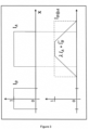
- Figure 4 is an illustration in 1D of the fact that the indicator of a Minkowski sum is not generally equal to the convolution of the two indicators, but they do share the same support.
- Equation 10 the right hand side of the inequalities in 12 is everywhere positive. So, now the complementary expressions in Equations 10 and 12 can be combined into a single bound on the indicator function of the Minkowski sum, I A k r ⁇ 1 2 ⁇ A ⁇ ⁇ ⁇ B k , ⁇ ⁇ r + ⁇ k I A ⁇ I ⁇ B k r
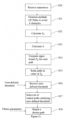
- FIG 11 is a flow chart illustrating a planning method comprising various aspects described herein.
- a manoeuvre is received from the planner A6.
- Multiple paths are generated to avoid K obstacles at step S11 eg. by an RRT algorithm.
- Factors G ⁇ and G are calculated across all obstacles. Although these are shown in order S12, S13, it will readily be appreciated that they could be calculated in a different order, or indeed simultaneously (as they are not interdependent).
- the upper bound F D is computed for each path using equation 18. In each computation for each path, the same value of G ⁇ or G is utilised for the obstacles which have been detected for this set of candidate paths.
- the paths are ranked in order of the computed upper bound.
- the ranked paths may be returned from the simulator to the planner.
- a user-defined threshold is received at step S16. This user-defined threshold may be a threshold on an acceptable level of primary risk, and may therefore set a certain value of F D below which paths are considered not safe enough.
- a set of ranked paths is selected which satisfy the user-defined threshold.
- At step S18 on operating path is chosen from the selected set of ranked paths, using a path selection parameter, for example comfort or efficiency.
- the ability to receive a user-defined threshold on primary risk opens up many useful possibilities.
- An externally defined threshold of risk may be applied and candidate paths (across all obstacles) which do not satisfy that level of risk may be deselected.
- This enables for example a regulatory or insurance body to apply a threshold of safety, and the techniques described herein ensure that that can be met in the path planning. It further enables candidate paths which have not been deselected to remain available such that other path selection parameters can be utilised, for example comfort or efficiency as mentioned.
- This provides a convenient way of handling the potential difficulty of optimising both for a primary risk (collisions) and other nevertheless important factors. This has a number of possible applications.
- on-board sensors are responsible for detecting the environment and providing sensor data which is supplied to object detection algorithms.
- Object detection or recognition may be hampered by a number of aspects for example, it is possible that accuracy of recognition may differ between different object classes. Put simply, some objects may be more reliably detected than others.
- the present approach enables an operating path to be selected from candidate paths which achieves a minimum level of safety for all object recognition classes regardless of their accuracy. It may be that in path planning the robot can avoid collisions with obstacles in certain object classes at a higher level of safety (due to increased accuracy of detection for example), but at least a minimum level of safety is guaranteed across all object classes.
- Shape models for obstacles have been mentioned earlier.
- One way of determining the shape of an obstacle is to access a shape model for that kind of obstacle.
- a shape model may be a rectangle or ellipse of certain dimensions.
- pedestrians and other small moving objects
- Another way of determining the shape would be to use the object recognition algorithms to actually determine a particular shape for each obstacle. This is likely to be more complex but the techniques described herein could also be used in such a circumstance.
- a Closed Loop variant CL-RRT of the RRT algorithm is used to generate hypothetical paths in the environment, draw from the kinodynamicmodel for a particular robot. See for example Y. Kuwata, J. Teo, G. Fiore, S. Karaman, E. Frazzoli, and J. P. How, Real-time motion planning with applications to autonomous urban driving, IEEE Trans. Control Systems Tech., 17, 5, 1105-1118, 2009 and S. M. LaValle, Rapidly-exploring random trees: A new tool for path planning, Tech Rep., 1998 . This has the advantage of generating typically smooth paths, that are plausible paths for that robot. Then the risk bound is calculated for each generated path.
- a 2D simulation is used in which a rectangular robot of size 2mx 4m navigates along continuous paths, defined as the progression of full pose over time (though visualisations only depict the centroid).
- a simulation scenario is defined as a collection of obstacles within the environment, each specified as a shape (a subset of 2), and pose, together with positional uncertainty, as well as start and target poses for the ego vehicle.
- the three simulated scenarios used here resemble sections of a car park: two each with just two car as obstacles ( Figures 5A and 5B ), and a third with a more complex arrangement ( Figure 6 ).
- 400 paths are generated at random by CL-RRT.
- the uncertainty over each obstacle's position is modelled as a two- dimensional Gaussian distribution with standard deviation 30 cm, which is 15% of each obstacle's width.
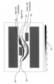
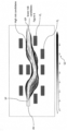
- Figures 5A and 5B show paths for two different simulated environments.
- a set of candidate paths are generated with fixed start SP and end poses EP.
- the dark objects are obstacles, O1. O2 etc. whose position is known with an uncertainty visualised here as a shaded halo.
- Risk bounds F D on each path are represented by different shades of grey, on the logarithmic scale S2 shown. Safer paths maintain greater clearance around obstacles as expected. Some risky paths involve squeezing through a narrow gap. In the second scenario ( Figure 5B ), the robot AV is able to squeeze through a narrow gap, but at some considerable risk of collision. In Figure 6 , a more complex environment is shown with more obstacles O i , and again higher values of the bound F D on the risk of collision correspond to tighter clearances.
- Figure 6 shows paths with varying values of F D , with tighter clearances when the bound F D on collision risk is high. Risk bounds are shown on same scale as Figure 5 .
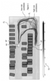
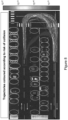
- Figure 1 an aerial view of a car park is shown, with a set of candidate paths for the robot AV generated by CL-RRT, between fixed start and end points.
- Obstacle vehicle shapes O i are represented as bounding rectangles.
- the obstacles here are 35 cars with shapes given by the bounding boxes shown in a fixed line, and uncertainties in location visualised as a slightly darker "fuzzy" halo around each bounding box.
- the robot vehicle AV has a set of candidate paths, evaluated here as high risk (dark grey) to low risk (white) according to the scale shown. Bounds on collision risk are represented by different shades of grey as on the logarithmic scale S1 shown. Some higher risk paths involve squeezing through a narrow gap.
- Error in estimated position of the obstacle-cars is Gaussian with standard deviation of 0.3m.
- the candidate paths are shown in different shades of grey according to the computed value of the bound on collision risk. This turns out to include safer paths with collision risk down to 10 -5 and below, and riskier paths, above 10 -2 risk of collision, that involve squeezing through a narrow gap.
- the FPR algorithm computes the bound F D on the exact risk P D computed as in (Equation 2) and (6).
- the slack in the bound is evaluated in several situations to see how close the bound is in practice.
- Tree nodes are chosen for expansion according to their scores. It discretises steering and accelerator input ranges when expanding the random tree, to generate realisable trajectories, and in order to restrict abrupt steering or velocity changes. Nodes in the RRT are scored based on their proximity to the goal, and similarity to its orientation and velocity.
- the approach described herein to safe motion planning bounds the risk of collision for candidate paths in configuration space.
- An acceptably safe path is then taken to be one that satisfies F D ⁇ ⁇ , for some user-supplied threshold ⁇ on risk.
- the FPR algorithm builds on a probabilistic framework for calculating collision risk, and uses the convolution trick to render these computations in linear time in N and K. Amongst trajectories deemed safe enough, there is then freedom to optimise for other criteria such as rider comfort and travel time.
- the on-board computer system A1 of the AV comprises execution hardware capable of executing algorithms encoded in software (computer programs) to carry out the above functions.
- the execution hardware can be general purpose or special purpose execution hardware, or any combination thereof, it will generally comprise one or more processors such as central processing units (CPUs) and which may operate in conjunction with specialized hardware such as, but not limited to, accelerators (e.g. GPU(s)), field programmable gate-arrays (FPGAs) or other programmable hardware, and/or application-specific integrated circuits (ASICs) etc.
- the on-board computer system may be highly sophisticated, possibly with specialized computer hardware tailored to implement the models and algorithms in question.
- the architecture of the AV on-board computer system A1 at both the hardware level and the functional/software level may take numerous forms.
- functional components and the like embodied in a computer system - such as the data processing component A2, prediction component A4 and AV planner A6 - are high-level representation of particular functionality implemented by the computer system, i.e. functions performed by whatever (combination of) general purpose and/or specialized hardware of the computer system that is appropriate in the circumstances.
- the invention also contemplates an off-board simulation environment where similar code may be executed on off-board computer hardware.
- a computer-implemented method of evaluating different paths A of an object in the presence of K obstacles comprising:
- the method, wherein the step of calculating F D includes calculating an upper bound which is given by F D ⁇ ⁇ ⁇ A ⁇ x G ⁇ x + ⁇ I A x G x
- dA ⁇ is the bounding contour of the path A
- ⁇ A ⁇ approximates a delta-function ridge along that contour
- G ⁇ as well as G are functions which do not depend on A .
- G ⁇ 1 2 ⁇ k ⁇ B k , ⁇ ⁇ p k
- ⁇ B k ⁇ is a delta-function ridge along the bounding contour of the shape B k of the obstacle k
- p k is a density function representing the position of the obstacle centre.
- G ⁇ k ⁇ k I B k ⁇ p k
- ⁇ k 1/ area ( B k )
- I Bk is the indicator function of the shape B k of the obstacle k
- p k is a density function representing the position of the obstacle centre.
- the method further comprising the step of determining, for each obstacle and each path A, whether its shape B k lies inside the path A .
- the method further comprising the step of calculating the indicator function I Ak for an obstacle having a shape B k lying inside the path A using a convolution of the two indicator functions I A and ⁇ Bk .
- an upper bound on the indicator function I Ak for each obstacle is calculated as follows: I A k x ⁇ 1 2 ⁇ A ⁇ ⁇ ⁇ B k , ⁇ ⁇ + ⁇ k I A ⁇ I ⁇ B k where ⁇ B k and ⁇ A are the boundary contours of said obstacle and the path, respectively, I A is the indicator function of the path A, and ⁇ Bk is the indicator function of the shape B k .
Landscapes
- Engineering & Computer Science (AREA)
- Physics & Mathematics (AREA)
- Automation & Control Theory (AREA)
- General Physics & Mathematics (AREA)
- Remote Sensing (AREA)
- Radar, Positioning & Navigation (AREA)
- Aviation & Aerospace Engineering (AREA)
- Human Computer Interaction (AREA)
- Transportation (AREA)
- Mechanical Engineering (AREA)
- Electromagnetism (AREA)
- Multimedia (AREA)
- Computer Vision & Pattern Recognition (AREA)
- Theoretical Computer Science (AREA)
- Control Of Position, Course, Altitude, Or Attitude Of Moving Bodies (AREA)
Description
- This disclosure relates to path planning in mobile robots such as autonomous vehicles (AVs).
- Mobile robotic systems that can autonomously plan their paths in complex environments are becoming increasingly more prevalent. An example of such a rapidly emerging technology is autonomous vehicles that can navigate by themselves on urban roads. Such vehicles must not only perform complex manoeuvres among people and other vehicles, but they must often do so while guaranteeing stringent constraints on the probability of adverse events occurring, such as collision with these other agents in the environments. In one study, it is estimated that publicly deployable autonomous vehicles must achieve less than 1 collision in hundreds of millions of miles driven in order for their maximum failure rates to be established as acceptable.
- An autonomous vehicle, also known as a self-driving vehicle, refers to a vehicle which has a sensor system for monitoring its external environment and a control system that is capable of making and implementing driving decisions automatically using those sensors. This includes in particular the ability to automatically adapt the vehicle's speed and direction of travel based on inputs from the sensor system. A fully autonomous or "driverless" vehicle has sufficient decision-making capability to operate without any input from a human driver. However the term autonomous vehicle as used herein also applies to semi-autonomous vehicles, which have more limited autonomous decision-making capability and therefore still require a degree of oversight from a human driver.
- Other mobile robots are being developed, for example for carrying freight supplies in internal and external industrial zones. Such mobile robots would have no people on board. Autonomous air mobile robots (drones) are also being developed. The sensory input available to such a mobile robot can often be noisy. Typically, the environment is perceived through sensors such as based on stereo vision or LiDAR, requiring not only signal processing for smoothing or noise removal, but also more complex "object finding" algorithms, such as for the drivable surface or other agents in the environment.
- Uncertainty arises directly from sensor noise, and then indirectly through perception algorithms that detect discrete obstacles or impassable terrain.
- The issue of safety in control and motion planning has been investigated from a number of different methodological directions.
- In early attempts within the robotics community, treatment of safety was closely associated with the notions of robustness to modelling errors in control theory. In the context of feedback control design, the robust control theory provides techniques to determine the single controller that can simultaneously guarantee a desired performance level for a family of possible target system models. This basic notion can be extended to the case of hybrid nonlinear dynamical systems and optimal control specifications through the concept of reachable sets, which can be computed using techniques such as level set methods. Recent extensions have included the use of Gaussian Process based learning of a robot's internal dynamics model, to enable such reachability computations with physical robots.
- Other current approaches consider safety in the context of human-robot interaction, where one is also interested in considerations such as modulating physical forces and human factors associated with the psychology of interaction. The core question of avoiding collision states in motion planning is dealt with in these works through the definition of safe zones and operating envelopes, which are not unlike the reachable sets mentioned above. In many applications, the resulting solutions may be overly conservative - leading to 'frozen robots'. In work drawing on robust optimization and stochastic programming, some researchers have posed the problem of motion planning as one of chance-constrained optimization. Following the above mentioned approaches to robust control, these works use set-bounded models of uncertainty and pose the search for paths as a problem of convex programming. In another recent example, the authors calculate rectangular bounds associated with uncertainty in location of obstacles, to determine the safe space within which RRT (Rapidly Exploring Random Tree) style algorithms can operate. As discussed later, the approach described in the present disclosure will improve upon these computations, particularly in the case of close interactions in tight spaces - such as in urban driving.
- Reference is made to papers authored by Christian Laugier, Jorge Rios-Martinez and Anne Spalanzani, who calculate probabilistic risk of collision of mobile robots and utilise this to define a risk guided search such as the Risk -RRT. In a paper entitled " Understanding human interaction for probabilistic autonomous navigation using Risk-RRT approach, (IEEE Int. Conf. IROS, 2011.) Laugier et al show that, in the context of posing environmental uncertainty in occupancy grids, integrals over multiple grids, one per obstacle, can be combined non-linearly to compute the total risk of collision. Fulgency et al "Risk based motion planning and navigation in uncertain dynamic environment" discloses another Risk-RRT based planning method.
- State of the art object detection algorithms tend to be based on methods that imply a limit on the achievable accuracy and reliability of detections. It is realistic to expect such perception modules to be able to provide a probability distribution over poses of each detected object in the scene. Achieving safe motion planning in such a setting requires the motion planning methods to take into account the probability of unsafe events (such as a collision of the robot with another agent), providing at least approximate assurance regarding the (non-)occurrence of these events.
- Guibas et al "Bounded Uncertainty Maps for Path Planning" teaches sampling-based motion planning based on an uncertainty roadmap in a robot's collision space. A path is selected based on a cost function that trades off distance of travel against collision risk.
- The core problem addressed herein is that of safe and computationally efficient motion planning in an imprecisely known environment. In some embodiments, the method receives as input detection of objects in the environment along with probability distributions over pose, such as over their centroid position when the shape model is known. This defines the space within which paths are searched. The first step is to determine the probability of a collision event occurring (i.e., the spatial extent of the robot and the spatial extent of any obstacle having an overlap) along any given path. This core computation may then be used to modify a variety of motion synthesis methods. For instance, the Rapidly Exploring Random Tree algorithm can utilise this probability within the search process. Likewise, a variational formulation of optimal control could include this within the cost term.
- In order to navigate an encountered driving scenario safely and effectively, an autonomous vehicle planner needs to be able to plan paths which can enable collision free behaviour or at least determine an upper bound on collision risk. One context of path planning is to implement a manoeuvre in a sequence of manoeuvres which have been determined to be executed in an encountered scenario. The manoeuvre may be implemented by one of a number of candidate paths (or trajectories). The techniques described herein can be used to calculate a bound on the probability of collision which can be used to stratify candidate trajectories according to their degree of risk. Then, within a user-defined threshold for an acceptable level of primary risk, motion synthesis techniques could optimise for secondary criteria such as comfort and efficiency.
- According to one aspect of the invention there is provided a computer-implemented method of planning a path for a mobile robot in the presence of K obstacles where K is at least one, as recited in
claim 1; - In the described embodiments the upper bound is further based on the shape (s) of the obstacles.
- In one aspect herein, the computational load for calculating the upper bound for all paths A after the first is independent of the number of obstacles.
- Calculating the upper bound may comprise computing the sum of the probability of collision of each obstacle with the autonomous vehicle by computing an integral of the product of a first term depending on the path A and a second term dependent on the number of obstacles and the density function of each obstacle but independent of the path A.
- The second term may be calculated in an initial calculation and then the upper bound computed using the calculated second term for each different path.
- In one embodiment the method further comprises the step of determining, for each obstacle and each path A, whether its shape Bk lies inside the path A. However in the described embodiments, this step is not needed as the steps of the computation described herein inherently account for that.
- In one embodiment, the step of calculating the upper bound FD includes calculating the integral for the case when the shape BK lies outside the path

- where ∂Ao is the bounding contour of the path A, ∂Ao(x) approximates a delta-
- function ridge along that contour, and Gσ is the second term which does not depend on the path A.
- Gσ may be calculated as follows:

- In one embodiment, the step of calculating the upper bound for the case when the shape BK lies inside the path comprises computing the integral ∫IA (x)G(x) wherein G is calculated as follows:

- where Ak = 1 / area(Bk), IBK is the indicator function of the shape Bk of the obstacle
- k and pk is a density function representing the probabilistic position of the obstacle at a canonical point of the obstacle.
- In certain cases, the shapes Bk are modelled as zero dimensional and the upper bound is given by


- For example , pedestrians may be modelled as point sources .
- In one aspect, which significantly reduces the computation complexity, the method comprises:
- computing at least one path independent function as a combination of the density functions for the obstacles; and
- for each of a plurality of candidate paths, determining an upper bound of the total probability of obstacle collision along that path, by integrating the path independent function over the swept area;
- wherein the path independent function is independent of the candidate path and the upper bound is computed for each candidate path without recomputing the path independent function.
- The upper bound for each candidate path is an upper bound on the sum of individual obstacle collision probabilities along that path, but may be computed without determining any of the individual obstacle collision probabilities, and instead, by integrating the path independent function over the swept area.
- The K obstacles may be identified using a perception module based on sensory input available to the mobile robot while mobile in its environment. Alternatively, the perception module may take simulated sensory input to implement the method in an off board simulator. In this context, simulated input may be real data which has been gathered earlier, but the simulator is not running in real time on the robot.
- The step of determining the shape BK may comprise accessing a shape model for the obstacle. in another aspect, the invention provides a data processing system configured to plan a path for a mobile robot and comprising a computer and memory holding computer code which when executed by the computer carries out a method as defined above.
- The data processing system may be embodied in a simulator, on board or off board the robot.
- The invention provides in another aspect a computer program product comprising instructions which, when the program is executed by a computer, cause the computer to carry out a method as defined above.
- The invention provides in another aspect a computer-readable storage medium comprising instructions which, when executed by a computer, cause the computer to carry out a method as defined above.
- The computer program product may be stored on a computer readable data carrier in non transitory form, or may be embodied in a data carrier signal.
- A further aspect of the invention provides a computer implemented method of planning a path for a mobile robot in the presence of K obstacles where K is at least one, the method comprising:
- determining a set of candidate paths, all candidate paths being from a common start point to a common end point;
- providing for each candidate path an upper bound on the total probability of at least one collision between the mobile robot and the K obstacles as a safety parameter; and
- ranking the candidate paths in order of the safety parameter to enable selection of one of the candidate paths from the ranked paths.
- A threshold for safety may be received and the ranked candidate paths which do not satisfy the threshold for safety can be deselected. The safety threshold may be received from an external body, such as an insurance company or regulator and programmed into the planner/ simulator. It may readily be altered without disturbing the planning method because it is applied as a filter after the paths have been ranked. It guarantees that a minimum safety threshold can be met.
- A path selection parameter may then be used to select an operating path from the ranked paths which have not been deselected. The path selection parameter can optimise for comfort or efficiency for example, in a set of paths having a guaranteed minimum safety.
- The presence of K obstacles may be carried out by at least one sensor on the robot while mobile in its environment by capturing images and recognising obstacles in the images according to different object recognition classes based on accuracy of recognition.
- By using the above method, a minimum threshold for safety is attained by a selected operating path for all object recognition classes of objects captured in the images. It may be improved on for certain object classes, but a minimum may be guaranteed by the techniques herein.
- Another aspect of the invention provides a computer implemented method of planning a path for a mobile robot in the presence of K obstacles where K is at least one, the method comprising:
- determining a set of candidate paths, all candidate paths being from a common start point to a common end point;
- receiving a threshold for safety and deselecting candidate paths of the set which do not satisfy the threshold for safety, and
- using a path selection parameters to select an operating path from the candidate paths which have not been deselected.
- The method can comprise the step of providing for each candidate path in the set an upper bound on the total probability of at least one collision between the robot and the K obstacles as a safety parameter, and using the safety parameter in comparison with the threshold for safety for deselecting candidate paths.
- The path selection parameter can comprise at least one of comfort and efficiency.
- A further aspect of the invention provides a computer implemented method of planning a path for a mobile robot in the presence of K obstacles, where K is at least one, wherein each of the K obstacles has a shape model indicating a shape BK of the obstacle and a density function PK (X) representing the probabilistic position of said obstacle, the method comprising:
- repeating the following steps for at least two different paths A;
- choosing a path A, where A is a swept area of the robot within a given time interval; and
- calculating based on the density function of each obstacle in the swept path an upper bound on the total probability of at least one collision FD between the robot and the K obstacles.
- A further aspect provides a data processing system configured to plan a path for a mobile robot and comprising a computer and memory holding computer code which when executed by the computer carries out a method As defined above .
- The data processing system may be embodied in a simulator external to, or on board the mobile robot.
- The invention also provides a computer program product comprising instructions which, when the program is executed by computer, cause the computer to carry out a method as defined above.
- For a better understanding of the present invention, and to show how embodiments of the same may be carried into effect, reference is made to the following Figures by way of non-limiting example in which:
-
Figure 1 is a representation based on data taken from an aerial view of a car-park illustrating the robot planning problem, with trajectories shown in shades of grey according to risk of collision. -
Figure 2 is a diagram illustrating a Minkowski Sum showing a path π with swept area A, dilated by Minkowski sum with obstacle of shape BK, to give the expanded swept area AK. -
Figure 3 are graphs illustrating convolution and the Minkowski sum. -
Figure 4 is a graphical representation of a contour convolution in which the indicator function of the Minkowski sum of sets A and B is approximated via contour convolution. -
Figures 5A and5B illustrates visualisation of paths for two different simulated. -
Figure 6 illustrates visualisation of paths in an environment with more obstacles. -
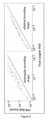
Figure 7 is a graph comparing the complexity and performance of the FPR (Fast Path Risk) computation described herein of the bound FD on collision risk, using the car park data fromFigure 1 , with a Laugier computation. -
Figure 8 is a representation of data from an aerial view of the car-park with the vehicles represented as elliptical shapes. -
Figure 9 is a plot of bounds on collision risk plotted for elliptical and rectangular bounding obstacle shapes in the car-park data ofFigure 1 and8 . -
Figure 10 is a schematic block diagram of an on-board control system for an AV. -
Figure 11 is a flow chart of a path planning method. -
Figure 12 is a visualisation of the motion planning problem for mobile robots. - As mobile robots and autonomous vehicles become increasingly prevalent in human centred environments, there is a need to develop techniques which seek to guarantee collision free behaviour, or at least bound the risk. Perceptual modules which receive sensory input data provide only noisy estimates of objects and it is appropriate to represent the environment probabilistically. Embodiments of the present invention introduce methods of path planning which enable a number of candidate paths to be ranked according to a safety parameter. A Fast Path Risk brackets (FPR) algorithm is described herein which efficiently calculates a bound on the probability of collision which can be used to stratify candidate trajectories according to their degree of risk. Then, within the user-defined threshold for an acceptable level of primary risk, motion synthetic techniques might be utilised to optimise for secondary criteria such as comfort or efficiency.
- Embodiments of the present invention provide a number of different novel and useful aspects. One contribution is the use in the FPR algorithm of a 'convolution trick' to factor integrals which are used to compute the bound on the collision risk. As a result, given K obstacles and N candidate paths, the computational load is reduced to O (N+K) compared with conventional techniques at O (NK). According to another aspect, candidate paths may be ranked in order of safety based on the upper bound on the total probability of at least one collision between the robot and K obstacles.
- According to another aspect, candidate paths may be filtered (e.g. deselected) on the basis of a user-defined threshold, and then a path selected based on other parameters (for example comfort and efficiency) from the filtered (non-deselected) set.
- Example embodiments of the present invention are described in detail below. First some useful context to the invention is described.
-
Figure 10 shows a highly schematic functional block diagram of certain functional components embodied in an on-board computer system A1 of an AV (ego vehicle), namely a data processing component A2, simulation component A5 and an AV planner A6. The AV is given as a non-limiting example of a mobile robot. - The data processing component A2 receives sensory input in the form of sensor data from an on-board sensor system A8 of the AV. The on-board sensor system A8 can take different forms but generally comprises a variety of sensors such as image capture devices (cameras), LiDAR units etc., satellite-positioning sensor(s) (GPS etc.), motion sensor(s) (accelerometers, gyroscopes etc.) etc., which collectively provide rich sensor data from which it is possible to extract detailed information about the surrounding environment and the state of the AV and other actors (vehicles, pedestrians etc.) within that environment.
- Note however that the present-techniques are not limited to using image data and the like captured using on-board optical sensors (image capture devices, LiDAR etc.) of the AV itself. The method can alternatively or additionally be applied using externally-captured sensor data, for example CCTV images etc. captured by external image capture units in the vicinity of the AV. In that case, at least some of the sensor inputs used to implement the method may be received by the AV from external sensor data sources via one or more wireless communication links. Moreover, the techniques described herein can be implemented off-board, that is in a computer system such as a simulator which is to execute path planning for modelling or experimental purposes. In that case, the sensory data may be taken from computer programs running as part of a simulation stack. In either context, a perception module A17 may operate on the sensor data to identify objects, as part of the data processing system A2.
- The data processing system A2 processes the sensor data in order to extract such information therefrom. This will generally involve various forms of machine learning (ML)/artificial intelligence (Al) processing. Functions of the data processing system A2 that are relevant in the present context include localization (block A10) and object detection (block A12).
- Localization is performed to provide awareness of the surrounding environment and the AV's location within it. A variety of localization techniques may be used to this end, including visual and map-based localization. By way of example, reference is made to
United Kingdom patent Application No. 1812658.1 - Object detection is applied to the sensor data to detect and localize external objects within the environment such as vehicles, pedestrians and other external actors which may contribute obstacles to the AV. This may for example comprise a form of 3D bounding box detection, wherein a location, orientation and size of objects within the environment and/or relative to the ego vehicle is estimated. This can for example be applied to (3D) image data such as RGBD (red green blue depth.), LiDAR point cloud etc. This allows the location and other physical properties of such external actors to be determined on the map. Object detection may be carried out using a perceptual model in a perception module A17. In an on-board context, the perceptual model utilises the received sensor data. In an off-board context the perceptual model may utilise data derived from actual or simulated sensors, pre-stored or generated by a computer program. Perceptual models and their limitations are discussed later.
- The AV planner A6 uses the extracted information about the ego's surrounding environment and the external agents within it as a basis for planning path for the AV. The AV planner A6 makes various high-level decisions and then increasingly lower-level decisions that are needed to implement the higher-level decisions. The end result is a series of real-time, low level action decisions. In order to implement those decisions, the AV planner A6 generates control signals, which are input, at least in part, to a drive mechanism A16 of the AV, in order to control the speed and heading of the vehicle (e.g. though steering, breaking, accelerating, changing gear) etc. Control signals are also generated to execute secondary actions such as signalling.
- Similar control signals may be generated in an off-board simulators and supplied to computer programs implementing models of other parts of the AV.
- A scenario extraction component A3 determines an encountered driving scenario for the ego vehicle using outputs of the data processing component A2. The determined driving scenario comprises driving scenario parameters which are extracted from the captured sensor data, and which provide a representation of a real-world scenario that has been encountered by the AV that is concise but sufficiently detailed to be used as a basis for realistic simulations.
- The simulator A5 receives the parameters of the encountered driving scenario and can run simulations based on those parameters. These are simulations of what might happen in the encountered driving scenario under different assumptions. These simulations are used as a basis for AV planning, in which the AV planner A6 runs multiple simulations with the aim of determining a globally optimal sequence of manoeuvres to be taken in the encountered driving scenario to execute a defined goal (i.e. achieve a desired outcome, such as reaching a particular location on the map). In one example described in our Patent Application No.
1816853.4 - When the ego vehicle is travelling, it must plan which manoeuvres to perform in order to execute a defined goal.
- When the ego vehicle encounters an actual driving scenario it needs to navigate, the planning module A6 reasons systematically about the different possible outcomes of different ego manoeuvres (i.e. manoeuvres which the AV planner A6 of the ego vehicle might take) in the encountered driving scenario. For example a manoeuvre may determine that the AV needs to travel from its present location (starting point SP) to a certain endpoint EP. The determined manoeuvre is supplied to the simulator A5 which generates a number of candidate paths as will be described, each associated with a computed bound on collision risk. The candidate paths may be returned to the planner A6 to select a suitable path to execute.
- For example, the paths can be synthesised for each goal using a Rapidly Exploring Random Tree (RRT) model. A space of predicted paths (search space) is defined based on the reference location for each goal and the current location r0 of the external vehicle. The search space is then randomly sampled (based on randomized input parameters), in order to determine the set of n paths, and a likelihood of each of those paths. To simulate n paths for each goal, the relevant parameters of the RRT are randomised n times to perform n appropriately based random searches of the search space. In the present disclosure, the probabilistic risk of collision along a given trajectory may be calculated, and used to rank the candidate trajectories by safety. This in turn provides the likelihood of each sampled path on the assumption that the external vehicle is more likely to take safer paths to execute the goal in question.
- The approach described herein is based on probabilistic robotics, wherein environmental uncertainty is posed probabilistically in the form of occupancy grids. However, the present disclosure seeks to relax several assumptions. Firstly, the fact that collision probabilities are not independent from cell to cell in an occupancy grid representation is taken into account. Instead, the probability of collision at one cell is directly coupled to that at a nearby cell, via the latent variable of true object pose. Secondly, the grid representation is reconsidered and an alternative computational approach is adopted that allows paths and object shapes to be modelled in a continuous fashion, deferring approximations to a much later stage in the procedure.
- A key contribution of the techniques described herein is a faster procedure for calculating integrals associated with the calculation of collision risk. This is achieved through the use of convolutions over boundary shapes. Given the shapes and uncertain location of obstacles in an environment, the problem is to estimate the risk of collision from taking a sequence of actions (i.e., traversing along a candidate path), given a description of the objects in the environment for a set of hypothetical paths. This risk can be posed in terms of the probability distribution for environment by the obstacles on the path swept by a moving robot during a specified time interval along that path.
-
Figure 12 is a visualisation of the motion planning problem faced by a robot AV. The three curves represent possible paths C1, C2, C3 that the robot could traverse. The environment is represented by the two white cars O1, O2 whose position is known only up to probabilities, depicted by the distribution (over the centroids). The outcome of the computations is an assignment of risk of collision to each curve which defines a rank ordering (here C1 is most preferred and C3 is least preferred). - In the present disclosure it is assumed that freespace in the plane is defined deterministically, and that a robot of known shape translates and rotates in freespace. In addition, discrete "tethered" obstacles k = 1 . . . , K of known shape and uncertain location are introduced. The problem is then, over a (short) time-interval t ∈ [0, ... , T ] to:
- Generate N hypothetical paths in configuration space for the robot.
- Bound the probabilistic risk of collision, for each path: a bound FD is computed on the risk of collision for each path. The FPR algorithm introduced here computes a bound FD on risk of collision, which is then available for use in motion synthesis. Its computational complexity is O(N + K), compared with the O(NK) of earlier techniques.
- The following inputs to the risk computation are assumed:
- Freespace: it is assumed that freespace F is defined to be a subset of

- Robot: assumed to have a deterministic spatial extent and to be manoeuvrable in translation and rotation. Over the interval t ∈ [0, . . . , T], it sweeps out the set A in the plane of r = (x, y).
- Obstacle shape: the kth obstacle is assumed to have deterministic shape and mean orientation represented by the set BK.
- Tethered obstacle: tethering here means specifying a probability distribution pk(r) for the location of the kth obstacle, taking into account: i) variability arising from any possible motion over the time-interval [0, ... , T ]; and ii) modelled uncertainty in object detector output. Obstacle locations are assumed to be mutually independent - arising from independent sensor observations.
- Obstacle rotation: treated as part of its shape so, to the extent that an obstacle may rotate over the time interval [0, ... , T ], that rotation must be absorbed in a deterministic expansion of the set BK.
- This treatment of obstacle rotation is a limitation of the framework described herein which, however, is reasonable if the time interval [0, ... , T ] is short, so rotation is limited.
- Consider an environment consisting of a set of K obstacles. These obstacles are typically detected by perceptual modules whose outputs are uncertain, hence we treat them as probabilistic. The position of each obstacle centre (or suitable canonical point, with respect to which all geometric computations can be reframed) is a random variable given by the density function pK (r), where

- The probability of collision between the robot and the kth obstacle (which we will sometimes write as 'obstacle k'), if that obstacle were a point obstacle, could be written as

- Now the total probability of collision is computed using the techniques of the Laugier et al paper reference earlier as


- The inventors have perceived that the computation of FD in
equation 3 can be made more efficient, i.e., of order O (1), by factoring it as:

- So, the probability of collision with the obstacle may be rewritten as

Figure 2 . - In prior search based planning algorithms, the Minkowski sums for AK must be recomputed for each new path A that is conjectured, and for every obstacle, BK. This becomes inefficient when K, the number of obstacles, is large. In the present disclosure, there is presented a way to replace these repeated O (K) computations by an O (1) computation.
- Note that the integral in
Equation 6 can be rewritten as the convolution of two functions, evaluated at the origin,
- The inventors have noted that a connection between the Minkowski sum of two sets, and the convolution operator * applied to the indicator functions of the two sets may be used to advantage in this context. The connection is laid out in
Equation 8.

- In general, it need not be the case that the indicator of a Minkowski sum is simply (proportional to) the convolution of the two indicator functions (see
Figure 3 ), but over a restricted portion of the plane - corresponding to the case when the obstacle BK lies inside the robot path A, the following equality holds,

- This provides a formula for calculating IAk when Bk (r) ⊂ A. The following sets out a corresponding calculation for the case when Bk (r) ⊄ A.
- Using contours to bound the integral.
- The complementary component of the Minkowski sum, IAk can be bounded using a convolution of using the bounding contours of the obstacles, ∂BK, and of the robot, ∂AK, to obtain an upper bound on any integral of the form ∫Akf(r), and in particular on the collision probability in
Equation 2. - Given the set A, the delta function ridge around its boundary ∂A is calculated as,


- This is illustrated in
Figure 4 which is an illustration in 1D of the fact that the indicator of a Minkowski sum is not generally equal to the convolution of the two indicators, but they do share the same support. - As with
equation 10, the right hand side of the inequalities in 12 is everywhere positive. So, now the complementary expressions inEquations 10 and 12 can be combined into a single bound on the indicator function of the Minkowski sum,
- As this bounds holds everywhere, we may write,

- Returning to the earlier expression for the collision probability, in
equation 2,
- Using the associativity of the convolution operator, this may be rewritten as,

- Finally,

- Summing up over obstacles, the bound on number of collisions is,


- Note that G and Gσ are independent of A and do not need to be recomputed every time A changes. So, the repeated computation of the bound (Equation 18) for N different swept paths A would indeed have complexity be O(N+K). That is, the path computations are independent of the number of obstacles - once the initial calculations of G and Gσ have been carried out. The above "convolution test" gives a Fast Path Risk (FPR) method to calculate the bound on the number of collisions, summarised in
Algorithm 1. (Shown in Annexe A). - That the indicator function for the Minkowski sum (in the limit that σ→0), in the inequality of
Equation 10, is indeed bounded can be shown as follows
- In the case that BK (x)∩A=φ both sides of
equation 17 are 0. Elsewhere, and given that BK (x)⊄A, the contours of A and BK must intersect at least twice. In that case,

- In the limit when σ→0, since the indicator function IAK (x) has
value 1 whenever the contours intersect, theformula 17 does indeed hold. -
Figure 11 is a flow chart illustrating a planning method comprising various aspects described herein. At step S10 a manoeuvre is received from the planner A6. Multiple paths are generated to avoid K obstacles at step S11 eg. by an RRT algorithm. Factors Gσ and G are calculated across all obstacles. Although these are shown in order S12, S13, it will readily be appreciated that they could be calculated in a different order, or indeed simultaneously (as they are not interdependent). At step S14 the upper bound FD is computed for each path using equation 18. In each computation for each path, the same value of Gσ or G is utilised for the obstacles which have been detected for this set of candidate paths. At step S15 the paths are ranked in order of the computed upper bound. The ranked paths may be returned from the simulator to the planner. A user-defined threshold is received at step S16. This user-defined threshold may be a threshold on an acceptable level of primary risk, and may therefore set a certain value of FD below which paths are considered not safe enough. At step S 17 a set of ranked paths is selected which satisfy the user-defined threshold. At step S18 on operating path is chosen from the selected set of ranked paths, using a path selection parameter, for example comfort or efficiency. - The ability to receive a user-defined threshold on primary risk opens up many useful possibilities. An externally defined threshold of risk may be applied and candidate paths (across all obstacles) which do not satisfy that level of risk may be deselected. This enables for example a regulatory or insurance body to apply a threshold of safety, and the techniques described herein ensure that that can be met in the path planning. It further enables candidate paths which have not been deselected to remain available such that other path selection parameters can be utilised, for example comfort or efficiency as mentioned. This provides a convenient way of handling the potential difficulty of optimising both for a primary risk (collisions) and other nevertheless important factors. This has a number of possible applications.
- For example, on-board sensors are responsible for detecting the environment and providing sensor data which is supplied to object detection algorithms. Object detection or recognition may be hampered by a number of aspects for example, it is possible that accuracy of recognition may differ between different object classes. Put simply, some objects may be more reliably detected than others. The present approach enables an operating path to be selected from candidate paths which achieves a minimum level of safety for all object recognition classes regardless of their accuracy. It may be that in path planning the robot can avoid collisions with obstacles in certain object classes at a higher level of safety (due to increased accuracy of detection for example), but at least a minimum level of safety is guaranteed across all object classes.
- Shape models for obstacles have been mentioned earlier. One way of determining the shape of an obstacle is to access a shape model for that kind of obstacle. For example, if the obstacle has been identified as a vehicle, a shape model may be a rectangle or ellipse of certain dimensions. According to another example, pedestrians (and other small moving objects) may be modelled as zero dimensional shapes. Note that this does not mean they become invisible with respect to the planning, but are mathematically treated as a zero dimensional shape. In effect, they have been reduced to point obstacles.
- Another way of determining the shape would be to use the object recognition algorithms to actually determine a particular shape for each obstacle. This is likely to be more complex but the techniques described herein could also be used in such a circumstance.
- Experiments have been carried out to demonstrate that sets of randomly generated trajectories, for a particular environment configuration, can be efficiently labelled by the FPR algorithm, according to the bound FD on the risk of collision for each path. The FPR algorithm is agnostic as to the motion planner used to synthesise the candidate trajectories and is generally compatible with state of the art methods for motion planning (as outlined for example in C. Katrakazas, M. Quddus, W.-H. Chen, and L. Deka, Real-time motion planning methods for autonomous on-road driving, Transportation Rsch Part C: Emerging Technologies, 60, 416-442, 2015. A Closed Loop variant CL-RRT of the RRT algorithm is used to generate hypothetical paths in the environment, draw from the kinodynamicmodel for a particular robot. See for example Y. Kuwata, J. Teo, G. Fiore, S. Karaman, E. Frazzoli, and J. P. How, Real-time motion planning with applications to autonomous urban driving, IEEE Trans. Control Systems Tech., 17, 5, 1105-1118, 2009 and S. M. LaValle, Rapidly-exploring random trees: A new tool for path planning, Tech Rep., 1998. This has the advantage of generating typically smooth paths, that are plausible paths for that robot. Then the risk bound is calculated for each generated path.
- First the results demonstrate the FPR algorithm for three simulated environments, then for a real environment taken from an aerial view. In each case, higher risk paths take tighter lines around obstacles, as would be expected. The experiments show: i) how close the bound on risk is to the true risk; and ii) that the use in FPR of the "convolution trick", which improves computational complexity from O(NK) to O(N + K) as explained earlier, leads to substantial reductions in practical computation times.
- In the experiments, a 2D simulation is used in which a rectangular robot of size 2mx 4m navigates along continuous paths, defined as the progression of full pose over time (though visualisations only depict the centroid). A simulation scenario is defined as a collection of obstacles within the environment, each specified as a shape (a subset of 2), and pose, together with positional uncertainty, as well as start and target poses for the ego vehicle.
- The three simulated scenarios used here resemble sections of a car park: two each with just two car as obstacles (
Figures 5A and5B ), and a third with a more complex arrangement (Figure 6 ). In each case, 400 paths are generated at random by CL-RRT. The uncertainty over each obstacle's position is modelled as a two- dimensional Gaussian distribution with standard deviation 30 cm, which is 15% of each obstacle's width.Figures 5A and5B show paths for two different simulated environments. A set of candidate paths are generated with fixed start SP and end poses EP. The dark objects are obstacles, O1. O2 etc. whose position is known with an uncertainty visualised here as a shaded halo. Risk bounds FD on each path are represented by different shades of grey, on the logarithmic scale S2 shown. Safer paths maintain greater clearance around obstacles as expected. Some risky paths involve squeezing through a narrow gap. In the second scenario (Figure 5B ), the robot AV is able to squeeze through a narrow gap, but at some considerable risk of collision. InFigure 6 , a more complex environment is shown with more obstacles Oi, and again higher values of the bound FD on the risk of collision correspond to tighter clearances. -
Figure 6 shows paths with varying values of FD, with tighter clearances when the bound FD on collision risk is high. Risk bounds are shown on same scale asFigure 5 . - In
Figure 1 an aerial view of a car park is shown, with a set of candidate paths for the robot AV generated by CL-RRT, between fixed start and end points. Obstacle vehicle shapes Oi are represented as bounding rectangles. The obstacles here are 35 cars with shapes given by the bounding boxes shown in a fixed line, and uncertainties in location visualised as a slightly darker "fuzzy" halo around each bounding box. The robot vehicle AV has a set of candidate paths, evaluated here as high risk (dark grey) to low risk (white) according to the scale shown. Bounds on collision risk are represented by different shades of grey as on the logarithmic scale S1 shown. Some higher risk paths involve squeezing through a narrow gap. Error in estimated position of the obstacle-cars is Gaussian with standard deviation of 0.3m. The candidate paths are shown in different shades of grey according to the computed value of the bound on collision risk. This turns out to include safer paths with collision risk down to 10-5 and below, and riskier paths, above 10-2 risk of collision, that involve squeezing through a narrow gap. - Experimental results given here illustrate the computational benefits of the FPR approach for evaluating bounds on risk. In
Figure 7 , empirical data is presented regarding the computational complexity of the present method compared to the baseline of computing the integral in Equation 6) directly.Figure 7 shows that computing the FPR bound on risk is significantly faster than exact computation via Laugier integrals. This is true in absolute terms, thanks to the use of efficiently implemented convolution, in place of Minkowski sum. It is also true in complexity, giving almost constant computation time with respect to the number K of obstacles, cf. linear growth. In absolute terms, even for one obstacle, average runtime is 9 times faster for FPR, owing to the use of efficiently implemented convolution in place of Minkowski sum. Then for increasing numbers of obstacles, runtime becomes almost constant with the number of obstacles at 9.4mc/path, cf. linear growth for direct computation of the Laugier integrals (6) for each obstacle. This is consistent with O(N +K) complexity c.f O(NK) complexity (for N evaluated paths), as expected from the theory outlined above. - A consideration of how tight is the bound on collision risk.
- The FPR algorithm computes the bound FD on the exact risk PD computed as in (Equation 2) and (6). The slack in the bound is evaluated in several situations to see how close the bound is in practice.
- Consider the simplest interesting situation with one square robot and an identical square obstacle, at various relative orientations and distances (from 0.75 of a square diameter up to 1.75 diameters), and where p1(r) is Gaussian with s.d. of 0.25 of a square diameter.
- Statistics are averaged over all the paths in the car-park data, representing the car-obstacle shapes Bk as rectangles.
- The rectangle shapes above are replaced with bounding ellipses, as in
Figure 8 . Bounds FD on collision risk are calculated here using elliptical rather than rectangular bounding shapes for the obstacles. This produces tighter bounds, so risk values FD are generally lower than forFigure 1 . - For the two squares, the bound is quite tight, ceding a factor of just 1.9 in risk on average. For the car park, the bounds are rather loose, with a factor of 8.9 of slack on average. When ellipses are used in place of rectangles, the slack is tightened to a factor of 4.7 on average. These slack factors occur more or less uniformly at high and low risk, as
Figure 9 shows. InFigure 9 , bounds FD on collision risk are plotted for elliptical and rectangular bounding obstacle shapes. Risk bounds have, on average, a factor of up to an order of magnitude slack for rectangular shapes, and that is true both at low and high risk. Bounds are tighter for elliptical obstacle shapes. One reason on why the the bound is slacker for rectangles than ellipses is because configurations in which the robot rectangle is almost tangential to an obstacle rectangle occur frequently, causing a spike in the contour-convolution (seeFigure 4 ). This effect is abated when the bounding obstacle shapes are ellipses, since extended tangency is avoided. - As described above, an augmented version of the CL-RRT planner, with probabilistic sampling is used in the above examples, similar to other approaches for heuristically biasing RRT growth as described for example in C. Urmson and R. Simmons, "Approaches for heuristically biasing rrt growth", in IEEE Int. Conf. IROS, 2, 1178-1183, 2003. Tree nodes are chosen for expansion according to their scores. It discretises steering and accelerator input ranges when expanding the random tree, to generate realisable trajectories, and in order to restrict abrupt steering or velocity changes. Nodes in the RRT are scored based on their proximity to the goal, and similarity to its orientation and velocity. The kth tethered obstacle is made deterministic, for the purposes of CL-RRT, taking the shape Bk at the mean location over pk. Throughout the experiments freespace is discretized on a grid with a resolution of 5 cm/px. The constant for Gaussian convolution, σ = 1 grid square, is just big enough for good numerical behaviour. All of the numerical computations are implemented using the GPU-enabled Python module for linear algebra CuPy.
- The approach described herein to safe motion planning bounds the risk of collision for candidate paths in configuration space. An acceptably safe path is then taken to be one that satisfies FD ≤ θ, for some user-supplied threshold θ on risk. The FPR algorithm builds on a probabilistic framework for calculating collision risk, and uses the convolution trick to render these computations in linear time in N and K. Amongst trajectories deemed safe enough, there is then freedom to optimise for other criteria such as rider comfort and travel time.
- At the hardware level, the on-board computer system A1 of the AV comprises execution hardware capable of executing algorithms encoded in software (computer programs) to carry out the above functions. Whilst the execution hardware can be general purpose or special purpose execution hardware, or any combination thereof, it will generally comprise one or more processors such as central processing units (CPUs) and which may operate in conjunction with specialized hardware such as, but not limited to, accelerators (e.g. GPU(s)), field programmable gate-arrays (FPGAs) or other programmable hardware, and/or application-specific integrated circuits (ASICs) etc. Given the need to perform complex data processing operations, often using sophisticated and complex ML/Al models, with sufficient accuracy and speed (often in real-time) to ensure safe and reliable operation, the on-board computer system may be highly sophisticated, possibly with specialized computer hardware tailored to implement the models and algorithms in question. Particularly given the speed at which innovation is progressing in the field of AI, it will be appreciated that the architecture of the AV on-board computer system A1 at both the hardware level and the functional/software level may take numerous forms. Herein, functional components and the like embodied in a computer system - such as the data processing component A2, prediction component A4 and AV planner A6 - are high-level representation of particular functionality implemented by the computer system, i.e. functions performed by whatever (combination of) general purpose and/or specialized hardware of the computer system that is appropriate in the circumstances. As noted, the invention also contemplates an off-board simulation environment where similar code may be executed on off-board computer hardware.
- In the above description there are laid out various aspects of path planning for a mobile robot. The following steps are discussed. Not all of these steps need to be performed in an efficient computation as described earlier.
- A computer-implemented method of evaluating different paths A of an object in the presence of K obstacles, comprising:
- ▪ determining, for each of the K obstacles, the shape Bk and a density function pk (x) representing the position of said obstacle;
- ▪ repeating the following steps for at least two different paths A:
- choosing a path A, where A is the swept area of the object within a given time interval;
- calculating an upper bound on the total probability of at least one collision FD between the object and the K obstacles.
- The method wherein a path A having the smallest FD , preferably having FD = 0, is selected for navigating the object through the obstacles.
- The method, wherein the step of calculating FD includes calculating an upper bound which is given by

- where dAσ is the bounding contour of the path A, ∂Aσ approximates a delta-function ridge along that contour, and Gσ as well as G are functions which do not depend on A.
- The method wherein the computational load for calculating the upper bound for all paths A after the first is independent of the number of obstacles.
- The method wherein Gσ is calculated as follows:

- The method wherein G is calculated as follows:

- The method, wherein the shapes Bk are zero-dimensional as a result of which the upper bound is given by


- The method wherein

- The method further comprising the step of determining, for each obstacle and each path A, whether its shape Bk lies inside the path A.
- The method further comprising the step of calculating the indicator function IAk for an obstacle having a shape Bk lying inside the path A using a convolution of the two indicator functions IA and ĨBk.
- The method wherein the indicator function IAk for said obstacle having a shape Bk lying inside the path A is calculated as follows:

- The method wherein an upper bound on the indicator function IAk for an obstacle having a shape Bk overlapping with the path A is calculated using a convolution of the boundary contours of said obstacle ∂Bk and the path ∂A.
- The method wherein the upper bound is calculated as follows:

- The method wherein an upper bound on the indicator function IAk for each obstacle is calculated as follows:

- The method wherein the probability of collision PD(k) is the convolution of the indicator function IAk of the Minkowski sum Ak = A⊕Bk for said obstacle and a density function pk (x) representing the position of the obstacle centre, evaluated at the origin.
-

Claims (12)
- A computer-implemented method of planning a path for a mobile robot (AV) in the presence of K obstacles (01,02) where K is at least one, comprising:- determining, for each of the K obstacles (01, 02), a shape Bk and a density function pk(x) representing the probabilistic position of said obstacle;- computing at least one of the following path-independent functions:∘
 ∘ G = ∑ k λk I Bk * pk where
 - repeating the following steps for at least two different paths (C1, C2, C3):wherein the path independent function is independent of each path and the upper bound is computed for each path without recomputing the path independent-function; and∘ determining a swept area A of the mobile robot (AV) along the path within a given time interval, and∘ calculating an upper bound on the total probability of obstacle collision between the mobile robot and the K obstacles (01,02), by integrating said at least one path-independent function over the swept area A as:▪ ∫ ∂Aσ (r)Gσ (r) where ∂Aσ(r) approximates a delta-function ridge along a bounding contour of the swept area A, or▪ ∫ IA (r)G(r) where IA is the indicator function for the swept area A,- selecting, from the at least two different paths based on the calculated upper bounds, a path for navigating the mobile robot (AV) through the obstacles (01, 02).
 - The method according to claim 1 comprising ranking the paths based on the upper bound of the total probability of at least one collision.
- The method according to claim 2, wherein a path having the smallest FD, preferably having FD = 0, is selected for navigating the mobile robot (AV) through the obstacles (01, 02).
- The method according to one of the preceding claims wherein the upper bound is further based on the shapes of the obstacles.
- The method according to one of the preceding claims, wherein each shape Bk is modelled as zero dimensional and the upper bound is given by
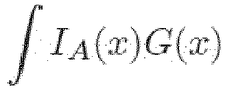
G = ∑ k pk and IA (x) is an indicator function of the swept area A. - The method according to one of the preceding claims, wherein the number of obstacles K>1.
- The method according to claim 6, wherein the upper bound for each candidate path is an upper bound on the sum of individual obstacle collision probabilities along that path, but is computed without determining any of the individual obstacle collision probabilities, and instead, by integrating the path-independent function over the swept area.
- The method of any preceding claim, wherein the upper bound is determined as:

- The method according to one of the preceding claims wherein the K obstacles are identified using a perception module based on sensory input available to the mobile robot while mobile in its environment, or simulated sensory input.
- The method according to one of the preceding claims wherein the step of determining the shape BK comprises accessing a shape model for the obstacle.
- A data processing system configured to plan a path for a mobile robot and comprising a computer and memory holding computer code which when executed by the computer carries out a method according to one of claims 1 to 10.
- A computer program product comprising instructions which, when the program is executed by a computer, cause the computer to carry out a method according to one of claims 1 to 10.
Applications Claiming Priority (2)
| Application Number | Priority Date | Filing Date | Title |
|---|---|---|---|
| GBGB1803292.0A GB201803292D0 (en) | 2018-02-28 | 2018-02-28 | Efficient computation of collision probabilities for safe motion planning |
| PCT/EP2019/054910 WO2019166517A1 (en) | 2018-02-28 | 2019-02-27 | Path planning in mobile robots |
Publications (2)
| Publication Number | Publication Date |
|---|---|
| EP3746855A1 EP3746855A1 (en) | 2020-12-09 |
| EP3746855B1 true EP3746855B1 (en) | 2024-05-08 |
Family
ID=61903271
Family Applications (2)
| Application Number | Title | Priority Date | Filing Date |
|---|---|---|---|
| EP19708289.4A Active EP3746855B1 (en) | 2018-02-28 | 2019-02-27 | Path planning in mobile robots |
| EP19708290.2A Active EP3746856B1 (en) | 2018-02-28 | 2019-02-27 | Path planning in mobile robots |
Family Applications After (1)
| Application Number | Title | Priority Date | Filing Date |
|---|---|---|---|
| EP19708290.2A Active EP3746856B1 (en) | 2018-02-28 | 2019-02-27 | Path planning in mobile robots |
Country Status (4)
| Country | Link |
|---|---|
| US (2) | US12242272B2 (en) |
| EP (2) | EP3746855B1 (en) |
| GB (1) | GB201803292D0 (en) |
| WO (2) | WO2019166517A1 (en) |
Families Citing this family (51)
| Publication number | Priority date | Publication date | Assignee | Title |
|---|---|---|---|---|
| WO2019241680A1 (en) * | 2018-06-15 | 2019-12-19 | Google Llc | Deep reinforcement learning for robotic manipulation |
| JP6838028B2 (en) * | 2018-10-31 | 2021-03-03 | ファナック株式会社 | Automatic program correction device and automatic program correction method |
| WO2020144970A1 (en) * | 2019-01-11 | 2020-07-16 | ソニー株式会社 | Action planning device, action planning method, and program |
| KR20200129045A (en) * | 2019-05-07 | 2020-11-17 | 모셔널 에이디 엘엘씨 | Systems and methods for planning and updating a vehicle's trajectory |
| EP3760507A1 (en) * | 2019-07-04 | 2021-01-06 | TTTech Auto AG | Safe trajectory selection for autonomous vehicles |
| US20210064031A1 (en) * | 2019-08-28 | 2021-03-04 | Zenuity Ab | Path planning for autonomous and semi-autonomous vehicles |
| US20220335183A1 (en) * | 2019-10-02 | 2022-10-20 | Nippon Telegraph And Telephone Corporation | Simulation device, learning device, simulation method, and simulation program |
| CN110703754B (en) * | 2019-10-17 | 2021-07-09 | 南京航空航天大学 | A trajectory planning method with highly coupled path and velocity for autonomous vehicles |
| US12005585B2 (en) * | 2019-12-27 | 2024-06-11 | Intrinsic Innovation Llc | Offline robot planning with online adaptation |
| EP4118507B1 (en) * | 2020-03-10 | 2025-05-07 | Seegrid Corporation | Self-driving vehicle path adaptation method |
| CN111506084B (en) * | 2020-05-19 | 2021-09-28 | 安徽江淮汽车集团股份有限公司 | Obstacle avoidance method, apparatus, device and storage medium for unmanned vehicle |
| US11886193B1 (en) * | 2020-06-04 | 2024-01-30 | Nuro, Inc. | Methods and apparatus for using scene-based metrics to gate readiness of autonomous systems |
| US11912300B2 (en) | 2020-09-30 | 2024-02-27 | GM Global Technology Operations LLC | Behavioral planning in autonomus vehicle |
| US11958688B2 (en) | 2020-10-19 | 2024-04-16 | Gideon Brothers d.o.o. | Area-based operation by autonomous robots in a facility context |
| CN112327620B (en) * | 2020-10-29 | 2022-05-17 | 广东省智能机器人研究院 | Robust control method and system for mobile robot considering obstacle avoidance |
| CN114440908B (en) * | 2020-10-31 | 2023-07-28 | 华为技术有限公司 | Method and device for planning driving path of vehicle, intelligent vehicle and storage medium |
| US11618479B2 (en) * | 2020-12-08 | 2023-04-04 | GM Global Technology Operations LLC | System, method and controller for graph-based path planning for a host vehicle |
| CN112558611B (en) * | 2020-12-15 | 2022-07-08 | 深圳市云视机器人有限公司 | Path planning method and device, computer equipment and storage medium |
| US12319315B2 (en) * | 2020-12-22 | 2025-06-03 | Waymo Llc | Autonomous vehicle trajectory computed using box-based probabilistic overlap model |
| CN112884256B (en) * | 2021-04-28 | 2021-07-27 | 深圳大学 | Path planning method and device, computer equipment and storage medium |
| CN113345008B (en) * | 2021-05-31 | 2022-05-24 | 湖南大学 | LiDAR dynamic obstacle detection method considering wheeled robot pose estimation |
| JP7688354B2 (en) * | 2021-07-12 | 2025-06-04 | 三菱重工業株式会社 | CONTROL DEVICE, UNMANNED SYSTEM, CONTROL METHOD, AND PROGRAM |
| CN115701524B (en) * | 2021-08-02 | 2024-05-28 | 郑州克莱门斯智能科技有限公司 | Construction method of space structure frame and navigation method and system using same |
| CN113485363B (en) * | 2021-08-02 | 2024-02-20 | 安徽理工大学 | Multi-step path planning method for underground coal mine robots based on membrane calculation and RRT |
| CN113485375B (en) * | 2021-08-13 | 2023-03-24 | 苏州大学 | Indoor environment robot exploration method based on heuristic bias sampling |
| CN113741484A (en) * | 2021-09-30 | 2021-12-03 | 暨南大学 | Path planning method, system and medium based on probability model |
| JP7716951B2 (en) | 2021-09-30 | 2025-08-01 | 本田技研工業株式会社 | Mobile object control device, mobile object, learning device, learning method, and program |
| US12384457B2 (en) | 2021-10-22 | 2025-08-12 | Gideon Brothers d.o.o. | Steering system for autonomous mobile robot |
| CN114089747B (en) * | 2021-11-05 | 2023-07-04 | 季华实验室 | Multi-AGV path planning method based on time slices |
| GB2612632B (en) * | 2021-11-08 | 2024-04-03 | Jaguar Land Rover Ltd | Control system for a vehicle and method thereof |
| DE102021212697A1 (en) * | 2021-11-11 | 2023-05-11 | Robert Bosch Gesellschaft mit beschränkter Haftung | Method for determining a movement path for a mobile device |
| KR20230073417A (en) * | 2021-11-18 | 2023-05-26 | 현대자동차주식회사 | Apparatus for controlling autonomous driving and method thereof |
| CN115240160A (en) * | 2021-11-26 | 2022-10-25 | 上海仙途智能科技有限公司 | Obstacle avoidance method, device and equipment for edge pasting cleaning of unmanned sweeper |
| CN114740843B (en) * | 2022-03-29 | 2024-12-06 | 江苏电子信息职业学院 | Environment modeling and path storage method for path planning of deformable two-state detection robot |
| US20230331252A1 (en) * | 2022-04-15 | 2023-10-19 | Gm Cruise Holdings Llc | Autonomous vehicle risk evaluation |
| US20230339502A1 (en) * | 2022-04-20 | 2023-10-26 | Gm Cruise Holdings Llc | Safety measurement of autonomous vehicle driving |
| CN114967691B (en) * | 2022-05-27 | 2025-06-27 | 美智纵横科技有限责任公司 | Robot control method, device, readable storage medium and robot |
| CN115230721B (en) * | 2022-08-31 | 2024-09-24 | 阿波罗智能技术(北京)有限公司 | Perception data processing method, device and autonomous driving vehicle |
| CN115344049B (en) * | 2022-09-14 | 2023-08-29 | 江苏天一航空工业股份有限公司 | Automatic path planning and vehicle control method and device for passenger boarding vehicle |
| CN115683145B (en) * | 2022-11-03 | 2024-06-11 | 北京踏歌智行科技有限公司 | A safe obstacle avoidance method for autonomous driving based on trajectory prediction |
| US12242371B2 (en) * | 2023-01-24 | 2025-03-04 | Dell Products L.P. | Bootstrap method for continuous deployment in cross-customer model management |
| CN116540701B (en) * | 2023-04-19 | 2024-03-05 | 广州里工实业有限公司 | Path planning method, system, device and storage medium |
| US20250083702A1 (en) * | 2023-09-12 | 2025-03-13 | The United States Of America As Represented By The Secretary Of The Navy | Method Of Machine-Learned Verification And Advance Notice Oracles For Autonomous Systems |
| CN117035602B (en) * | 2023-10-10 | 2023-12-15 | 成都思越智能装备股份有限公司 | Material conveying path optimizing method and device across conveying system |
| CN117806333B (en) * | 2024-02-29 | 2024-05-24 | 北京大学 | Target tracking track planning method and device for maintaining visibility in complex environment |
| CN118394092B (en) * | 2024-06-21 | 2024-11-08 | 南京邮电大学 | AGV multi-stage path planning method and system based on moss mouse algorithm |
| CN118894134B (en) * | 2024-10-09 | 2024-12-13 | 吉林大学 | Automatic driving automobile track planning method considering uncertainty of surrounding automobiles |
| CN120143827B (en) * | 2025-03-11 | 2025-08-12 | 成都智享科技有限公司 | A robot safe path planning method and system based on expansion distance |
| CN120085683B (en) * | 2025-04-30 | 2025-07-04 | 广东海洋大学 | Bionic fish robot underwater motion control system |
| CN120372723B (en) * | 2025-06-24 | 2025-09-05 | 北自所(北京)科技发展股份有限公司 | AMR task scene equipment parameter simulation generation method, device and storage medium |
| CN120886273B (en) * | 2025-09-29 | 2026-01-06 | 北京大学南昌创新研究院 | A humanoid robot fusion system with autonomous navigation |
Family Cites Families (4)
| Publication number | Priority date | Publication date | Assignee | Title |
|---|---|---|---|---|
| US7447593B2 (en) * | 2004-03-26 | 2008-11-04 | Raytheon Company | System and method for adaptive path planning |
| US10049578B2 (en) | 2015-06-29 | 2018-08-14 | Hitachi, Ltd. | Travel command generation device |
| WO2017214581A1 (en) * | 2016-06-10 | 2017-12-14 | Duke University | Motion planning for autonomous vehicles and reconfigurable motion planning processors |
| US10480952B2 (en) * | 2018-02-01 | 2019-11-19 | Didi Research America, Llc | Probabilistic navigation system and method |
-
2018
- 2018-02-28 GB GBGB1803292.0A patent/GB201803292D0/en not_active Ceased
-
2019
- 2019-02-27 EP EP19708289.4A patent/EP3746855B1/en active Active
- 2019-02-27 US US16/976,070 patent/US12242272B2/en active Active
- 2019-02-27 WO PCT/EP2019/054910 patent/WO2019166517A1/en not_active Ceased
- 2019-02-27 US US16/976,053 patent/US11768495B2/en active Active
- 2019-02-27 EP EP19708290.2A patent/EP3746856B1/en active Active
- 2019-02-27 WO PCT/EP2019/054911 patent/WO2019166518A1/en not_active Ceased
Also Published As
| Publication number | Publication date |
|---|---|
| US11768495B2 (en) | 2023-09-26 |
| US20210191404A1 (en) | 2021-06-24 |
| EP3746855A1 (en) | 2020-12-09 |
| GB201803292D0 (en) | 2018-04-11 |
| EP3746856A1 (en) | 2020-12-09 |
| WO2019166518A1 (en) | 2019-09-06 |
| US12242272B2 (en) | 2025-03-04 |
| US20220107646A1 (en) | 2022-04-07 |
| EP3746856B1 (en) | 2025-09-24 |
| WO2019166517A1 (en) | 2019-09-06 |
Similar Documents
| Publication | Publication Date | Title |
|---|---|---|
| US11768495B2 (en) | Path planning in mobile robots | |
| Xu et al. | System and experiments of model-driven motion planning and control for autonomous vehicles | |
| Li et al. | Real-time trajectory planning for autonomous urban driving: Framework, algorithms, and verifications | |
| Seraji et al. | Behavior-based robot navigation on challenging terrain: A fuzzy logic approach | |
| Andersen et al. | Trajectory optimization and situational analysis framework for autonomous overtaking with visibility maximization | |
| US8744648B2 (en) | Integrated framework for vehicle operator assistance based on a trajectory prediction and threat assessment | |
| Liu et al. | CommonRoad-Reach: A toolbox for reachability analysis of automated vehicles | |
| De Oliveira et al. | Trajectory planning for autonomous cars in low-structured and unstructured environments: A systematic review | |
| Sehn et al. | Along similar lines: Local obstacle avoidance for long-term autonomous path following | |
| Liu et al. | Radius: Risk-aware, real-time, reachability-based motion planning | |
| Blake et al. | FPR—Fast Path Risk algorithm to evaluate collision probability | |
| Chandler et al. | Model checking for closed-loop robot reactive planning | |
| Meerpohl et al. | Free-space polygon creation based on occupancy grid maps for trajectory optimization methods | |
| Tariq et al. | Frenet Corridor Planner: An Optimal Local Path Planning Framework for Autonomous Driving | |
| Chen et al. | From perception to control: an autonomous driving system for a formula student driverless car | |
| Hardy et al. | Contingency planning over probabilistic hybrid obstacle predictions for autonomous road vehicles | |
| Nasti et al. | Obstacle avoidance during robot navigation in dynamic environment using fuzzy controller | |
| CN120057021A (en) | Automatic driving decision method and device based on intelligent agent interaction active perception shielding | |
| Constantin et al. | A margin-based approach to threat assessment for autonomous highway navigation | |
| Althoff | Safety assessment for motion planning in uncertain and dynamic environments | |
| Yuan et al. | A novel obstacle avoidance method based on multi-information inflation map | |
| Misra et al. | Machine learning for autonomous vehicles | |
| Banerjee | Development of a simulation-based platform for autonomous vehicle algorithm validation | |
| Sudianto et al. | Sensor Fusion using Model Predictive Control for Differential Dual Wheeled Robot | |
| US20260048507A1 (en) | Motion planning and/or collision determination using continuous environment model |
Legal Events
| Date | Code | Title | Description |
|---|---|---|---|
| STAA | Information on the status of an ep patent application or granted ep patent |
Free format text: STATUS: UNKNOWN |
|
| STAA | Information on the status of an ep patent application or granted ep patent |
Free format text: STATUS: THE INTERNATIONAL PUBLICATION HAS BEEN MADE |
|
| PUAI | Public reference made under article 153(3) epc to a published international application that has entered the european phase |
Free format text: ORIGINAL CODE: 0009012 |
|
| STAA | Information on the status of an ep patent application or granted ep patent |
Free format text: STATUS: REQUEST FOR EXAMINATION WAS MADE |
|
| 17P | Request for examination filed |
Effective date: 20200902 |
|
| AK | Designated contracting states |
Kind code of ref document: A1 Designated state(s): AL AT BE BG CH CY CZ DE DK EE ES FI FR GB GR HR HU IE IS IT LI LT LU LV MC MK MT NL NO PL PT RO RS SE SI SK SM TR |
|
| AX | Request for extension of the european patent |
Extension state: BA ME |
|
| DAV | Request for validation of the european patent (deleted) | ||
| DAX | Request for extension of the european patent (deleted) | ||
| STAA | Information on the status of an ep patent application or granted ep patent |
Free format text: STATUS: EXAMINATION IS IN PROGRESS |
|
| 17Q | First examination report despatched |
Effective date: 20220513 |
|
| RAP3 | Party data changed (applicant data changed or rights of an application transferred) |
Owner name: FIVE AI LIMITED |
|
| GRAP | Despatch of communication of intention to grant a patent |
Free format text: ORIGINAL CODE: EPIDOSNIGR1 |
|
| STAA | Information on the status of an ep patent application or granted ep patent |
Free format text: STATUS: GRANT OF PATENT IS INTENDED |
|
| INTG | Intention to grant announced |
Effective date: 20231213 |
|
| RIN1 | Information on inventor provided before grant (corrected) |
Inventor name: SILVA, ALEXANDRE OLIVEIRA E Inventor name: MICO, ALEJANDRO BORDALLO Inventor name: EIRAS, FRANCISCO MARIA GIRBAL Inventor name: HAWASLY, MAJD Inventor name: PENKOV, SVETLIN VALENTINOV Inventor name: RAMAMOORTHY, SUBRAMANIAN Inventor name: BLAKE, ANDREW |
|
| GRAS | Grant fee paid |
Free format text: ORIGINAL CODE: EPIDOSNIGR3 |
|
| GRAA | (expected) grant |
Free format text: ORIGINAL CODE: 0009210 |
|
| STAA | Information on the status of an ep patent application or granted ep patent |
Free format text: STATUS: THE PATENT HAS BEEN GRANTED |
|
| AK | Designated contracting states |
Kind code of ref document: B1 Designated state(s): AL AT BE BG CH CY CZ DE DK EE ES FI FR GB GR HR HU IE IS IT LI LT LU LV MC MK MT NL NO PL PT RO RS SE SI SK SM TR |
|
| REG | Reference to a national code |
Ref country code: GB Ref legal event code: FG4D |
|
| REG | Reference to a national code |
Ref country code: CH Ref legal event code: EP |
|
| REG | Reference to a national code |
Ref country code: DE Ref legal event code: R096 Ref document number: 602019051884 Country of ref document: DE |
|
| REG | Reference to a national code |
Ref country code: IE Ref legal event code: FG4D |
|
| REG | Reference to a national code |
Ref country code: LT Ref legal event code: MG9D |
|
| REG | Reference to a national code |
Ref country code: NL Ref legal event code: MP Effective date: 20240508 |
|
| PG25 | Lapsed in a contracting state [announced via postgrant information from national office to epo] |
Ref country code: IS Free format text: LAPSE BECAUSE OF FAILURE TO SUBMIT A TRANSLATION OF THE DESCRIPTION OR TO PAY THE FEE WITHIN THE PRESCRIBED TIME-LIMIT Effective date: 20240908 |
|
| PG25 | Lapsed in a contracting state [announced via postgrant information from national office to epo] |
Ref country code: BG Free format text: LAPSE BECAUSE OF FAILURE TO SUBMIT A TRANSLATION OF THE DESCRIPTION OR TO PAY THE FEE WITHIN THE PRESCRIBED TIME-LIMIT Effective date: 20240508 |
|
| PG25 | Lapsed in a contracting state [announced via postgrant information from national office to epo] |
Ref country code: HR Free format text: LAPSE BECAUSE OF FAILURE TO SUBMIT A TRANSLATION OF THE DESCRIPTION OR TO PAY THE FEE WITHIN THE PRESCRIBED TIME-LIMIT Effective date: 20240508 Ref country code: FI Free format text: LAPSE BECAUSE OF FAILURE TO SUBMIT A TRANSLATION OF THE DESCRIPTION OR TO PAY THE FEE WITHIN THE PRESCRIBED TIME-LIMIT Effective date: 20240508 |
|
| PG25 | Lapsed in a contracting state [announced via postgrant information from national office to epo] |
Ref country code: GR Free format text: LAPSE BECAUSE OF FAILURE TO SUBMIT A TRANSLATION OF THE DESCRIPTION OR TO PAY THE FEE WITHIN THE PRESCRIBED TIME-LIMIT Effective date: 20240809 |
|
| PG25 | Lapsed in a contracting state [announced via postgrant information from national office to epo] |
Ref country code: PT Free format text: LAPSE BECAUSE OF FAILURE TO SUBMIT A TRANSLATION OF THE DESCRIPTION OR TO PAY THE FEE WITHIN THE PRESCRIBED TIME-LIMIT Effective date: 20240909 |
|
| REG | Reference to a national code |
Ref country code: AT Ref legal event code: MK05 Ref document number: 1685511 Country of ref document: AT Kind code of ref document: T Effective date: 20240508 |
|
| PG25 | Lapsed in a contracting state [announced via postgrant information from national office to epo] |
Ref country code: NL Free format text: LAPSE BECAUSE OF FAILURE TO SUBMIT A TRANSLATION OF THE DESCRIPTION OR TO PAY THE FEE WITHIN THE PRESCRIBED TIME-LIMIT Effective date: 20240508 |
|
| PG25 | Lapsed in a contracting state [announced via postgrant information from national office to epo] |
Ref country code: ES Free format text: LAPSE BECAUSE OF FAILURE TO SUBMIT A TRANSLATION OF THE DESCRIPTION OR TO PAY THE FEE WITHIN THE PRESCRIBED TIME-LIMIT Effective date: 20240508 |
|
| PG25 | Lapsed in a contracting state [announced via postgrant information from national office to epo] |
Ref country code: AT Free format text: LAPSE BECAUSE OF FAILURE TO SUBMIT A TRANSLATION OF THE DESCRIPTION OR TO PAY THE FEE WITHIN THE PRESCRIBED TIME-LIMIT Effective date: 20240508 |
|
| PG25 | Lapsed in a contracting state [announced via postgrant information from national office to epo] |
Ref country code: PL Free format text: LAPSE BECAUSE OF FAILURE TO SUBMIT A TRANSLATION OF THE DESCRIPTION OR TO PAY THE FEE WITHIN THE PRESCRIBED TIME-LIMIT Effective date: 20240508 |
|
| PG25 | Lapsed in a contracting state [announced via postgrant information from national office to epo] |
Ref country code: LV Free format text: LAPSE BECAUSE OF FAILURE TO SUBMIT A TRANSLATION OF THE DESCRIPTION OR TO PAY THE FEE WITHIN THE PRESCRIBED TIME-LIMIT Effective date: 20240508 |
|
| PG25 | Lapsed in a contracting state [announced via postgrant information from national office to epo] |
Ref country code: PT Free format text: LAPSE BECAUSE OF FAILURE TO SUBMIT A TRANSLATION OF THE DESCRIPTION OR TO PAY THE FEE WITHIN THE PRESCRIBED TIME-LIMIT Effective date: 20240909 Ref country code: PL Free format text: LAPSE BECAUSE OF FAILURE TO SUBMIT A TRANSLATION OF THE DESCRIPTION OR TO PAY THE FEE WITHIN THE PRESCRIBED TIME-LIMIT Effective date: 20240508 Ref country code: NO Free format text: LAPSE BECAUSE OF FAILURE TO SUBMIT A TRANSLATION OF THE DESCRIPTION OR TO PAY THE FEE WITHIN THE PRESCRIBED TIME-LIMIT Effective date: 20240808 Ref country code: NL Free format text: LAPSE BECAUSE OF FAILURE TO SUBMIT A TRANSLATION OF THE DESCRIPTION OR TO PAY THE FEE WITHIN THE PRESCRIBED TIME-LIMIT Effective date: 20240508 Ref country code: LV Free format text: LAPSE BECAUSE OF FAILURE TO SUBMIT A TRANSLATION OF THE DESCRIPTION OR TO PAY THE FEE WITHIN THE PRESCRIBED TIME-LIMIT Effective date: 20240508 Ref country code: IS Free format text: LAPSE BECAUSE OF FAILURE TO SUBMIT A TRANSLATION OF THE DESCRIPTION OR TO PAY THE FEE WITHIN THE PRESCRIBED TIME-LIMIT Effective date: 20240908 Ref country code: HR Free format text: LAPSE BECAUSE OF FAILURE TO SUBMIT A TRANSLATION OF THE DESCRIPTION OR TO PAY THE FEE WITHIN THE PRESCRIBED TIME-LIMIT Effective date: 20240508 Ref country code: GR Free format text: LAPSE BECAUSE OF FAILURE TO SUBMIT A TRANSLATION OF THE DESCRIPTION OR TO PAY THE FEE WITHIN THE PRESCRIBED TIME-LIMIT Effective date: 20240809 Ref country code: FI Free format text: LAPSE BECAUSE OF FAILURE TO SUBMIT A TRANSLATION OF THE DESCRIPTION OR TO PAY THE FEE WITHIN THE PRESCRIBED TIME-LIMIT Effective date: 20240508 Ref country code: ES Free format text: LAPSE BECAUSE OF FAILURE TO SUBMIT A TRANSLATION OF THE DESCRIPTION OR TO PAY THE FEE WITHIN THE PRESCRIBED TIME-LIMIT Effective date: 20240508 Ref country code: BG Free format text: LAPSE BECAUSE OF FAILURE TO SUBMIT A TRANSLATION OF THE DESCRIPTION OR TO PAY THE FEE WITHIN THE PRESCRIBED TIME-LIMIT Effective date: 20240508 Ref country code: AT Free format text: LAPSE BECAUSE OF FAILURE TO SUBMIT A TRANSLATION OF THE DESCRIPTION OR TO PAY THE FEE WITHIN THE PRESCRIBED TIME-LIMIT Effective date: 20240508 Ref country code: RS Free format text: LAPSE BECAUSE OF FAILURE TO SUBMIT A TRANSLATION OF THE DESCRIPTION OR TO PAY THE FEE WITHIN THE PRESCRIBED TIME-LIMIT Effective date: 20240808 |
|
| PG25 | Lapsed in a contracting state [announced via postgrant information from national office to epo] |
Ref country code: DK Free format text: LAPSE BECAUSE OF FAILURE TO SUBMIT A TRANSLATION OF THE DESCRIPTION OR TO PAY THE FEE WITHIN THE PRESCRIBED TIME-LIMIT Effective date: 20240508 |
|
| PG25 | Lapsed in a contracting state [announced via postgrant information from national office to epo] |
Ref country code: EE Free format text: LAPSE BECAUSE OF FAILURE TO SUBMIT A TRANSLATION OF THE DESCRIPTION OR TO PAY THE FEE WITHIN THE PRESCRIBED TIME-LIMIT Effective date: 20240508 |
|
| PG25 | Lapsed in a contracting state [announced via postgrant information from national office to epo] |
Ref country code: CZ Free format text: LAPSE BECAUSE OF FAILURE TO SUBMIT A TRANSLATION OF THE DESCRIPTION OR TO PAY THE FEE WITHIN THE PRESCRIBED TIME-LIMIT Effective date: 20240508 |
|
| PG25 | Lapsed in a contracting state [announced via postgrant information from national office to epo] |
Ref country code: SK Free format text: LAPSE BECAUSE OF FAILURE TO SUBMIT A TRANSLATION OF THE DESCRIPTION OR TO PAY THE FEE WITHIN THE PRESCRIBED TIME-LIMIT Effective date: 20240508 Ref country code: RO Free format text: LAPSE BECAUSE OF FAILURE TO SUBMIT A TRANSLATION OF THE DESCRIPTION OR TO PAY THE FEE WITHIN THE PRESCRIBED TIME-LIMIT Effective date: 20240508 |
|
| PG25 | Lapsed in a contracting state [announced via postgrant information from national office to epo] |
Ref country code: SM Free format text: LAPSE BECAUSE OF FAILURE TO SUBMIT A TRANSLATION OF THE DESCRIPTION OR TO PAY THE FEE WITHIN THE PRESCRIBED TIME-LIMIT Effective date: 20240508 |
|
| PG25 | Lapsed in a contracting state [announced via postgrant information from national office to epo] |
Ref country code: SM Free format text: LAPSE BECAUSE OF FAILURE TO SUBMIT A TRANSLATION OF THE DESCRIPTION OR TO PAY THE FEE WITHIN THE PRESCRIBED TIME-LIMIT Effective date: 20240508 Ref country code: SK Free format text: LAPSE BECAUSE OF FAILURE TO SUBMIT A TRANSLATION OF THE DESCRIPTION OR TO PAY THE FEE WITHIN THE PRESCRIBED TIME-LIMIT Effective date: 20240508 Ref country code: RO Free format text: LAPSE BECAUSE OF FAILURE TO SUBMIT A TRANSLATION OF THE DESCRIPTION OR TO PAY THE FEE WITHIN THE PRESCRIBED TIME-LIMIT Effective date: 20240508 Ref country code: EE Free format text: LAPSE BECAUSE OF FAILURE TO SUBMIT A TRANSLATION OF THE DESCRIPTION OR TO PAY THE FEE WITHIN THE PRESCRIBED TIME-LIMIT Effective date: 20240508 Ref country code: DK Free format text: LAPSE BECAUSE OF FAILURE TO SUBMIT A TRANSLATION OF THE DESCRIPTION OR TO PAY THE FEE WITHIN THE PRESCRIBED TIME-LIMIT Effective date: 20240508 Ref country code: CZ Free format text: LAPSE BECAUSE OF FAILURE TO SUBMIT A TRANSLATION OF THE DESCRIPTION OR TO PAY THE FEE WITHIN THE PRESCRIBED TIME-LIMIT Effective date: 20240508 |
|
| PG25 | Lapsed in a contracting state [announced via postgrant information from national office to epo] |
Ref country code: IT Free format text: LAPSE BECAUSE OF FAILURE TO SUBMIT A TRANSLATION OF THE DESCRIPTION OR TO PAY THE FEE WITHIN THE PRESCRIBED TIME-LIMIT Effective date: 20240508 |
|
| REG | Reference to a national code |
Ref country code: DE Ref legal event code: R097 Ref document number: 602019051884 Country of ref document: DE |
|
| PLBE | No opposition filed within time limit |
Free format text: ORIGINAL CODE: 0009261 |
|
| STAA | Information on the status of an ep patent application or granted ep patent |
Free format text: STATUS: NO OPPOSITION FILED WITHIN TIME LIMIT |
|
| 26N | No opposition filed |
Effective date: 20250211 |
|
| PG25 | Lapsed in a contracting state [announced via postgrant information from national office to epo] |
Ref country code: SI Free format text: LAPSE BECAUSE OF FAILURE TO SUBMIT A TRANSLATION OF THE DESCRIPTION OR TO PAY THE FEE WITHIN THE PRESCRIBED TIME-LIMIT Effective date: 20240508 |
|
| PG25 | Lapsed in a contracting state [announced via postgrant information from national office to epo] |
Ref country code: SE Free format text: LAPSE BECAUSE OF FAILURE TO SUBMIT A TRANSLATION OF THE DESCRIPTION OR TO PAY THE FEE WITHIN THE PRESCRIBED TIME-LIMIT Effective date: 20240508 |
|
| PG25 | Lapsed in a contracting state [announced via postgrant information from national office to epo] |
Ref country code: MC Free format text: LAPSE BECAUSE OF FAILURE TO SUBMIT A TRANSLATION OF THE DESCRIPTION OR TO PAY THE FEE WITHIN THE PRESCRIBED TIME-LIMIT Effective date: 20240508 |
|
| REG | Reference to a national code |
Ref country code: CH Ref legal event code: PL |
|
| PG25 | Lapsed in a contracting state [announced via postgrant information from national office to epo] |
Ref country code: LU Free format text: LAPSE BECAUSE OF NON-PAYMENT OF DUE FEES Effective date: 20250227 |
|
| PG25 | Lapsed in a contracting state [announced via postgrant information from national office to epo] |
Ref country code: CH Free format text: LAPSE BECAUSE OF NON-PAYMENT OF DUE FEES Effective date: 20250228 |
|
| GBPC | Gb: european patent ceased through non-payment of renewal fee |
Effective date: 20250227 |
|
| REG | Reference to a national code |
Ref country code: BE Ref legal event code: MM Effective date: 20250228 |
|
| REG | Reference to a national code |
Ref country code: DE Ref legal event code: R082 Ref document number: 602019051884 Country of ref document: DE Representative=s name: WESTPHAL, MUSSGNUG & PARTNER PATENTANWAELTE MI, DE |
|
| PG25 | Lapsed in a contracting state [announced via postgrant information from national office to epo] |
Ref country code: GB Free format text: LAPSE BECAUSE OF NON-PAYMENT OF DUE FEES Effective date: 20250227 |
|
| PG25 | Lapsed in a contracting state [announced via postgrant information from national office to epo] |
Ref country code: FR Free format text: LAPSE BECAUSE OF NON-PAYMENT OF DUE FEES Effective date: 20250228 |
|
| PG25 | Lapsed in a contracting state [announced via postgrant information from national office to epo] |
Ref country code: BE Free format text: LAPSE BECAUSE OF NON-PAYMENT OF DUE FEES Effective date: 20250228 |
|
| PG25 | Lapsed in a contracting state [announced via postgrant information from national office to epo] |
Ref country code: IE Free format text: LAPSE BECAUSE OF NON-PAYMENT OF DUE FEES Effective date: 20250227 |
|
| PGFP | Annual fee paid to national office [announced via postgrant information from national office to epo] |
Ref country code: DE Payment date: 20260213 Year of fee payment: 8 |