EP3746367B1 - Unit dose packaging system (udps) having child resistant locking feature with focused push button - Google Patents
Unit dose packaging system (udps) having child resistant locking feature with focused push button Download PDFInfo
- Publication number
- EP3746367B1 EP3746367B1 EP19748289.6A EP19748289A EP3746367B1 EP 3746367 B1 EP3746367 B1 EP 3746367B1 EP 19748289 A EP19748289 A EP 19748289A EP 3746367 B1 EP3746367 B1 EP 3746367B1
- Authority
- EP
- European Patent Office
- Prior art keywords
- tab
- button
- slide card
- edge
- inner slide
- Prior art date
- Legal status (The legal status is an assumption and is not a legal conclusion. Google has not performed a legal analysis and makes no representation as to the accuracy of the status listed.)
- Active
Links
- 238000004806 packaging method and process Methods 0.000 title description 7
- 239000011087 paperboard Substances 0.000 claims description 19
- 230000000994 depressogenic effect Effects 0.000 claims description 5
- 230000000717 retained effect Effects 0.000 claims description 4
- 230000000881 depressing effect Effects 0.000 claims description 3
- 238000000034 method Methods 0.000 description 5
- 238000007796 conventional method Methods 0.000 description 1
- 239000003814 drug Substances 0.000 description 1
- 238000012986 modification Methods 0.000 description 1
- 230000004048 modification Effects 0.000 description 1
Images


Classifications
-
- B—PERFORMING OPERATIONS; TRANSPORTING
- B65—CONVEYING; PACKING; STORING; HANDLING THIN OR FILAMENTARY MATERIAL
- B65D—CONTAINERS FOR STORAGE OR TRANSPORT OF ARTICLES OR MATERIALS, e.g. BAGS, BARRELS, BOTTLES, BOXES, CANS, CARTONS, CRATES, DRUMS, JARS, TANKS, HOPPERS, FORWARDING CONTAINERS; ACCESSORIES, CLOSURES, OR FITTINGS THEREFOR; PACKAGING ELEMENTS; PACKAGES
- B65D5/00—Rigid or semi-rigid containers of polygonal cross-section, e.g. boxes, cartons or trays, formed by folding or erecting one or more blanks made of paper
- B65D5/38—Drawer-and-shell type containers
-
- B—PERFORMING OPERATIONS; TRANSPORTING
- B31—MAKING ARTICLES OF PAPER, CARDBOARD OR MATERIAL WORKED IN A MANNER ANALOGOUS TO PAPER; WORKING PAPER, CARDBOARD OR MATERIAL WORKED IN A MANNER ANALOGOUS TO PAPER
- B31B—MAKING CONTAINERS OF PAPER, CARDBOARD OR MATERIAL WORKED IN A MANNER ANALOGOUS TO PAPER
- B31B50/00—Making rigid or semi-rigid containers, e.g. boxes or cartons
- B31B50/26—Folding sheets, blanks or webs
-
- B—PERFORMING OPERATIONS; TRANSPORTING
- B65—CONVEYING; PACKING; STORING; HANDLING THIN OR FILAMENTARY MATERIAL
- B65D—CONTAINERS FOR STORAGE OR TRANSPORT OF ARTICLES OR MATERIALS, e.g. BAGS, BARRELS, BOTTLES, BOXES, CANS, CARTONS, CRATES, DRUMS, JARS, TANKS, HOPPERS, FORWARDING CONTAINERS; ACCESSORIES, CLOSURES, OR FITTINGS THEREFOR; PACKAGING ELEMENTS; PACKAGES
- B65D75/00—Packages comprising articles or materials partially or wholly enclosed in strips, sheets, blanks, tubes, or webs of flexible sheet material, e.g. in folded wrappers
- B65D75/28—Articles or materials wholly enclosed in composite wrappers, i.e. wrappers formed by associating or interconnecting two or more sheets or blanks
- B65D75/30—Articles or materials enclosed between two opposed sheets or blanks having their margins united, e.g. by pressure-sensitive adhesive, crimping, heat-sealing, or welding
- B65D75/32—Articles or materials enclosed between two opposed sheets or blanks having their margins united, e.g. by pressure-sensitive adhesive, crimping, heat-sealing, or welding one or both sheets or blanks being recessed to accommodate contents
- B65D75/36—Articles or materials enclosed between two opposed sheets or blanks having their margins united, e.g. by pressure-sensitive adhesive, crimping, heat-sealing, or welding one or both sheets or blanks being recessed to accommodate contents one sheet or blank being recessed and the other formed of relatively stiff flat sheet material, e.g. blister packages, the recess or recesses being preformed
- B65D75/367—Articles or materials enclosed between two opposed sheets or blanks having their margins united, e.g. by pressure-sensitive adhesive, crimping, heat-sealing, or welding one or both sheets or blanks being recessed to accommodate contents one sheet or blank being recessed and the other formed of relatively stiff flat sheet material, e.g. blister packages, the recess or recesses being preformed and forming several compartments
-
- B—PERFORMING OPERATIONS; TRANSPORTING
- B65—CONVEYING; PACKING; STORING; HANDLING THIN OR FILAMENTARY MATERIAL
- B65D—CONTAINERS FOR STORAGE OR TRANSPORT OF ARTICLES OR MATERIALS, e.g. BAGS, BARRELS, BOTTLES, BOXES, CANS, CARTONS, CRATES, DRUMS, JARS, TANKS, HOPPERS, FORWARDING CONTAINERS; ACCESSORIES, CLOSURES, OR FITTINGS THEREFOR; PACKAGING ELEMENTS; PACKAGES
- B65D83/00—Containers or packages with special means for dispensing contents
- B65D83/04—Containers or packages with special means for dispensing contents for dispensing annular, disc-shaped, or spherical or like small articles, e.g. tablets or pills
- B65D83/0445—Containers or packages with special means for dispensing contents for dispensing annular, disc-shaped, or spherical or like small articles, e.g. tablets or pills all the articles being stored in individual compartments
- B65D83/0463—Containers or packages with special means for dispensing contents for dispensing annular, disc-shaped, or spherical or like small articles, e.g. tablets or pills all the articles being stored in individual compartments formed in a band or a blisterweb, inserted in a dispensing device or container
-
- A—HUMAN NECESSITIES
- A61—MEDICAL OR VETERINARY SCIENCE; HYGIENE
- A61J—CONTAINERS SPECIALLY ADAPTED FOR MEDICAL OR PHARMACEUTICAL PURPOSES; DEVICES OR METHODS SPECIALLY ADAPTED FOR BRINGING PHARMACEUTICAL PRODUCTS INTO PARTICULAR PHYSICAL OR ADMINISTERING FORMS; DEVICES FOR ADMINISTERING FOOD OR MEDICINES ORALLY; BABY COMFORTERS; DEVICES FOR RECEIVING SPITTLE
- A61J1/00—Containers specially adapted for medical or pharmaceutical purposes
- A61J1/03—Containers specially adapted for medical or pharmaceutical purposes for pills or tablets
- A61J1/035—Blister-type containers
-
- B—PERFORMING OPERATIONS; TRANSPORTING
- B65—CONVEYING; PACKING; STORING; HANDLING THIN OR FILAMENTARY MATERIAL
- B65D—CONTAINERS FOR STORAGE OR TRANSPORT OF ARTICLES OR MATERIALS, e.g. BAGS, BARRELS, BOTTLES, BOXES, CANS, CARTONS, CRATES, DRUMS, JARS, TANKS, HOPPERS, FORWARDING CONTAINERS; ACCESSORIES, CLOSURES, OR FITTINGS THEREFOR; PACKAGING ELEMENTS; PACKAGES
- B65D2215/00—Child-proof means
- B65D2215/04—Child-proof means requiring the combination of different actions in succession
-
- B—PERFORMING OPERATIONS; TRANSPORTING
- B65—CONVEYING; PACKING; STORING; HANDLING THIN OR FILAMENTARY MATERIAL
- B65D—CONTAINERS FOR STORAGE OR TRANSPORT OF ARTICLES OR MATERIALS, e.g. BAGS, BARRELS, BOTTLES, BOXES, CANS, CARTONS, CRATES, DRUMS, JARS, TANKS, HOPPERS, FORWARDING CONTAINERS; ACCESSORIES, CLOSURES, OR FITTINGS THEREFOR; PACKAGING ELEMENTS; PACKAGES
- B65D2583/00—Containers or packages with special means for dispensing contents
- B65D2583/04—For dispensing annular, disc-shaped or spherical or like small articles or tablets
- B65D2583/0445—For dispensing annular, disc-shaped or spherical or like small articles or tablets characterised by the shape of the container
- B65D2583/0454—Flat container with slide cover, i.e. the thickness of the container is slightly more than the thickness of one article
Definitions
- the present disclosure relates to unit dose packaging systems (UDPSs), and more particularly to child resistant UDPSs.
- UDPSs unit dose packaging systems
- US 6, 230, 893 there is disclosed a unit dose paperboard package having a locking feature, comprising an outer paperboard sleeve and an inner paperboard slide card lockably retained within said outer sleeve.
- the outer sleeve paperboard blank 2 includes, in part, extension panels 4 and 8, side panels 10, 18 and 26, cut away areas 12 and 14, node 16, legs 17, side panels 20 and 24, cut outs 21 and 28, end flaps 22 and 32 and release button 30.
- Legs 17 are elongations in cut away area 14 and are configured so as to inhibit the entire length of node 16 from deflecting.
- Release button 30 is cut within panel 26.
- the area of node 16 between legs 17 is slightly larger than the size of release button 30 which will cause node 16 to deflect only when release button 30 is pressed, thus adding to the child resistance features.
- Child resistant unit dose packaging systems require pressing a button or tab on an outer sleeve to release a blister back from the sleeve. Once the blisters are clear of the sleeve, a dose can be removed by pressing it out of the blister. The multiple steps required to actually obtain the product from the blister discourage and/or prevent children from being able to remove products from the blister pack.
- a unit dose paperboard package having a locking feature includes an outer paperboard sleeve and an inner paperboard slide card lockably retained within the outer sleeve, such that the outer sleeve includes a plurality of panels operatively connected to each other such that a top panel of the plurality of panels includes an inner slide card retaining aperture and an inner slide card releasing button defined thereon.
- the inner slide card includes one or more unit dose dispensing blisters and an inner slide card retaining and releasing panel located adjacent to the one or more unit dose dispensing blisters.
- the slide card release button includes a longitudinally extending tab defined by a cut in the sleeve, with a root of the tab between ends of the cut, and with a moveable tab edge opposite the root of the tab.
- the card retaining aperture extends longitudinally past the moveable tab edge in a first direction, but does not extend longitudinally past the root of the tab in a second direction opposite the first direction.
- the longitudinally extending tab has a length extending in a longitudinal direction from the moveable tab edge to the root of the tab, and the card retaining aperture can extend in the longitudinal direction less than one half of the length of the tab from the moveable tab edge towards the root.
- the card retaining aperture can terminate at either lateral end thereof in a laterally extending wing portion.
- the top panel can include a plurality of layers, e.g. connected together with the plurality of panels along fold lines, wherein the card retaining aperture is defined as an aperture in an inner layer of the plurality of layers, and wherein the tab of the slide card releasing button is defined in an outer layer of the plurality of layers.
- the card retaining aperture can include a catch edge configured to engage the inner slide card retaining and releasing panel to prevent removal of the slide card without depressing the button, and the inner slide card retaining aperture can include a button edge opposite the catch edge, wherein the button edge conforms to a contour of the moveable tab edge of the slide card release button.
- the cut defining the longitudinally extending tab can include a pair of spaced apart longitudinally extending side portions defining side edges of the longitudinally extending tab, wherein the button edge of the card retaining aperture conforms to the moveable tab edge and a portion of the side edges of the tab.
- the side portions of the cut defining the longitudinally extending tab can each terminate in a u-shaped terminus.
- the inner slide card retaining and releasing panel can be hingedly attached along a fold line to the inner slide card, with a catch edge opposite the fold line that engages the catch edge of the slide card retaining aperture to prevent removal of the inner slide card unless the button is depressed.
- the button and card retaining aperture can be configured so that direct pressing of the button releases the inner slide card, wherein releasing the inner slide card is inhibited for pressing near the button but not on the button
- a blank for an outer paperboard sleeve for a unit dose paperboard package includes a plurality of panels operatively connected to each other to form a sleeve for receiving an inner slide card with one or more unit dose dispensing blisters, wherein a top one of the panels includes an inner slide card retaining aperture and an inner slide card releasing button defined thereon.
- the slide card includes a card retaining aperture and a release button with a longitudinally extending tab as described above.
- Fig. 1 a partial view of an exemplary embodiment of a package in accordance with the disclosure is shown in Fig. 1 and is designated generally by reference character 100.
- Other embodiments of packages in accordance with the disclosure, or aspects thereof, are provided in Figs. 2-6 , as will be described.
- the systems and methods described herein can be used to prevent access, as in child proofing, to contents in unit dose packaging systems such as for pharmaceuticals.
- U.S. Patent No. 6,047,829 provides an explanation of a unit dose packaging system (UPDS), provides an explanation of how to form such a package from a paperboard blank which is assembled into an outer sleeve, provides an explanation of how to form an inner slide card, and provides an explanation for how to assemble the inner slide card into the outer sleeve to provide a locking mechanism in the closed position of the inner slide card and a mechanism for preventing complete removal of the inner slide card from the outer sleeve or shell.
- UPDS unit dose packaging system
- a unit dose paperboard package 100 with a locking feature in accordance with the present disclosure includes an outer paperboard sleeve 102 and an inner paperboard slide card 104 lockably retained within the outer sleeve 102.
- the button 120 In a closed position shown in Fig. 1 , the button 120 must be depressed in order to unlock the slide card 104 to access the contents of the slide card 104 in the open position shown in Fig. 2 .
- the contents of the inner slide card 104 e.g., contained within a plurality of unit dose dispensing blisters 108 of the slide card 104, can be accessed but the slide card 104 cannot be completely removed from the sleeve 102 due to a second locking mechanism described below which retains slide card 104 in the open end of the sleeve 102.
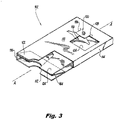
- the sleeve 102 includes a plurality of panels, e.g. panels 110, 112, 114, and 116, operatively connected to each other such that a top panel 110 includes an inner slide card retaining aperture 118 (shown in hidden lines in Fig. 3 ) and an inner slide card releasing button 120 defined thereon.
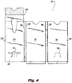
- the top panel 110 includes a plurality of layers 122 and 124, e.g. connected together with the plurality of panels 110, 112, 114, and 116 along fold lines 130 shown Fig. 4 , which shows a blank 101 for forming the sleeve 102.
- the card retaining aperture 118 is defined as an aperture, e.g., cut through, in the inner layer 124 of the top panel 110.
- the slide card release button 120 includes a longitudinally extending tab 126 defined by a cut 128 in the outer layer 122 of the top panel 110 of the sleeve 102.
- the tab 126 includes a root 132 of the tab 126 between ends 134 of the cut 128.
- the tab 126 includes a moveable tab edge 136 opposite the root 132 of the tab 126.
- the cut 128 defining the longitudinally extending tab 126 includes a pair of spaced apart longitudinally extending side portions 138 defining side edges of the longitudinally extending tab 126.
- the side portions 138 of the cut 128 each terminate in a u-shaped terminus 140.
- the longitudinally extending tab can have a length L extending in a longitudinal direction, e.g., along longitudinal axis A from the moveable tab edge 136 to the root 132 of the tab 126.
- the card retaining aperture 118 extends longitudinally past the moveable tab edge 136 in a first direction, as indicated by the length d1 in Fig. 5 , but does not extend longitudinally past the root 132 of the tab 126 in a second direction opposite the first direction, as indicated by the length d2 in Fig. 5 .
- the card retaining aperture 118 extends in the longitudinal direction less than one half of the length L of the tab 126 from the moveable tab edge 136 towards the root 132, i.e., d2 ⁇ 0.5 ⁇ L.
- d2 can be 40% of L.
- the card retaining aperture 118 terminates at either lateral end thereof in a laterally extending wing portion 142.
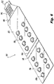
- the inner slide card 104 includes an inner slide card retaining and releasing panel 146 located adjacent to the unit dose dispensing blisters 108.
- An inner slide card retaining and releasing panel 146 is hingedly attached along a fold line 148 to the main panel 150 of the inner slide card 104.
- the retaining and releasing panel 146 includes a catch edge 152 opposite the fold line 148 that engages the catch edge 154 (identified in Fig. 5 ) of the slide card retaining aperture 118 to prevent removal of the inner slide card 104 unless the button 120 is depressed.
- the inner slide card 104 also includes a second panel 156, which includes additional unit dose dispensing blisters 108, and is connected to the main panel 150 by fold lines 158.
- the inner slide card retaining aperture 118 includes a button edge 160 opposite the catch edge 154.
- the button edge 160 conforms to a contour of the moveable tab edge 136 of the slide card release button 120 and to a portion of the side edges 138 of the tab 126.
- the button 120 and card retaining aperture 126 are configured so that direct pressing of the button 120 releases the inner slide card 104 when it is in the closed and locked position shown in Fig. 1 so the inner slide card can be opened to the open position shown in Fig. 2 , e.g. by lowering the catch edge 152 of the inner slide card 104 to clear the catch edge 154 of the sleeve 102. Releasing the inner slide card is inhibited when pressing near the button 120 but not on the button 120, e.g., pressing at locations in area 162 schematically indicated in Fig 5 .
- buttons 4 into a sleeve 102, how to assemble the slide card 104, and how to assemble the slide card 104 into the sleeve 102 so that improved direct pressing of the button 102 unlocks access to the slide card 104 when in the locked position, in accordance to this disclosure. Since direct pressing of the button 120 is required to release the inner slide card 104, the button press is more focused compared to traditional configurations, improving inadvertent opening and improving child proofing.
- the button and aperture configuration disclosed herein is also stronger and less likely to tear when pressed very hard compared to traditional configurations.
Description
- This application claims the benefit of priority under 35 U.S.C. §119(e) of
United States provisional application serial number 62/624853 filed on February 1, 2018 - The present disclosure relates to unit dose packaging systems (UDPSs), and more particularly to child resistant UDPSs. In
US 6, 230, 893 , there is disclosed a unit dose paperboard package having a locking feature, comprising an outer paperboard sleeve and an inner paperboard slide card lockably retained within said outer sleeve. The outer sleeve paperboard blank 2 includes, in part, extension panels 4 and 8, side panels 10, 18 and 26, cut away areas 12 and 14, node 16, legs 17, side panels 20 and 24, cut outs 21 and 28, end flaps 22 and 32 and release button 30. Legs 17 are elongations in cut away area 14 and are configured so as to inhibit the entire length of node 16 from deflecting. Release button 30 is cut within panel 26. The area of node 16 between legs 17 is slightly larger than the size of release button 30 which will cause node 16 to deflect only when release button 30 is pressed, thus adding to the child resistance features. - Child resistant unit dose packaging systems require pressing a button or tab on an outer sleeve to release a blister back from the sleeve. Once the blisters are clear of the sleeve, a dose can be removed by pressing it out of the blister. The multiple steps required to actually obtain the product from the blister discourage and/or prevent children from being able to remove products from the blister pack.
- In traditional child resistant unit dose packaging systems, it may be possible to release the blister pack from the sleeve by pressing near or around the actual button, which in some designs may not meet more stringent child proofing standards.
- The conventional techniques have been considered satisfactory for their intended purpose. However, there is an ever-present need for improved unit dose packaging systems. This disclosure provides a solution for this need.
- A unit dose paperboard package having a locking feature includes an outer paperboard sleeve and an inner paperboard slide card lockably retained within the outer sleeve, such that the outer sleeve includes a plurality of panels operatively connected to each other such that a top panel of the plurality of panels includes an inner slide card retaining aperture and an inner slide card releasing button defined thereon. The inner slide card includes one or more unit dose dispensing blisters and an inner slide card retaining and releasing panel located adjacent to the one or more unit dose dispensing blisters. The slide card release button includes a longitudinally extending tab defined by a cut in the sleeve, with a root of the tab between ends of the cut, and with a moveable tab edge opposite the root of the tab. The card retaining aperture extends longitudinally past the moveable tab edge in a first direction, but does not extend longitudinally past the root of the tab in a second direction opposite the first direction. The longitudinally extending tab has a length extending in a longitudinal direction from the moveable tab edge to the root of the tab, and the card retaining aperture can extend in the longitudinal direction less than one half of the length of the tab from the moveable tab edge towards the root.
- The card retaining aperture can terminate at either lateral end thereof in a laterally extending wing portion. The top panel can include a plurality of layers, e.g. connected together with the plurality of panels along fold lines, wherein the card retaining aperture is defined as an aperture in an inner layer of the plurality of layers, and wherein the tab of the slide card releasing button is defined in an outer layer of the plurality of layers.
- The card retaining aperture can include a catch edge configured to engage the inner slide card retaining and releasing panel to prevent removal of the slide card without depressing the button, and the inner slide card retaining aperture can include a button edge opposite the catch edge, wherein the button edge conforms to a contour of the moveable tab edge of the slide card release button. The cut defining the longitudinally extending tab can include a pair of spaced apart longitudinally extending side portions defining side edges of the longitudinally extending tab, wherein the button edge of the card retaining aperture conforms to the moveable tab edge and a portion of the side edges of the tab. The side portions of the cut defining the longitudinally extending tab can each terminate in a u-shaped terminus. The inner slide card retaining and releasing panel can be hingedly attached along a fold line to the inner slide card, with a catch edge opposite the fold line that engages the catch edge of the slide card retaining aperture to prevent removal of the inner slide card unless the button is depressed. The button and card retaining aperture can be configured so that direct pressing of the button releases the inner slide card, wherein releasing the inner slide card is inhibited for pressing near the button but not on the button
- A blank for an outer paperboard sleeve for a unit dose paperboard package includes a plurality of panels operatively connected to each other to form a sleeve for receiving an inner slide card with one or more unit dose dispensing blisters, wherein a top one of the panels includes an inner slide card retaining aperture and an inner slide card releasing button defined thereon. The slide card includes a card retaining aperture and a release button with a longitudinally extending tab as described above.
- These and other features of the systems and methods of the subject disclosure will become more readily apparent to those skilled in the art from the following detailed description of the preferred embodiments taken in conjunction with the drawings.
- So that those skilled in the art to which the subject disclosure appertains will readily understand how to make and use the devices and methods of the subject disclosure without undue experimentation, preferred embodiments thereof will be described in detail herein below with reference to certain figures, wherein:
-
Fig. 1 is a perspective view of an exemplary embodiment of a unit dose paperboard package constructed in accordance with the present disclosure, showing the outer sleeve and the inner slide card assembled together with the inner slide card stored inside the sleeve; -
Fig. 2 is a partially cross-sectional perspective view of the sleeve and inner slide card ofFig. 1 , showing the inner slide card extended from the sleeve for access to the contents thereof; -
Fig. 3 is a partially cross-sectional perspective view of the sleeve ofFig. 1 , showing the sleeve without the inner slide card; -
Fig. 4 is a plan view of a blank for the sleeve ofFig. 3 , showing the panels with the button and the card retaining aperture; -
Fig. 5 is a partially cut-away plan view of a portion of the sleeve ofFig. 1 , showing the button with the card retaining aperture shown partially in hidden lines; and -
Fig. 6 is a perspective view of the inner slide card ofFig. 1 , showing the retaining and releasing panel of the inner slide card. - Reference will now be made to the drawings wherein like reference numerals identify similar structural features or aspects of the subject disclosure. For purposes of explanation and illustration, and not limitation, a partial view of an exemplary embodiment of a package in accordance with the disclosure is shown in
Fig. 1 and is designated generally byreference character 100. Other embodiments of packages in accordance with the disclosure, or aspects thereof, are provided inFigs. 2-6 , as will be described. The systems and methods described herein can be used to prevent access, as in child proofing, to contents in unit dose packaging systems such as for pharmaceuticals. -
U.S. Patent No. 6,047,829 provides an explanation of a unit dose packaging system (UPDS), provides an explanation of how to form such a package from a paperboard blank which is assembled into an outer sleeve, provides an explanation of how to form an inner slide card, and provides an explanation for how to assemble the inner slide card into the outer sleeve to provide a locking mechanism in the closed position of the inner slide card and a mechanism for preventing complete removal of the inner slide card from the outer sleeve or shell. - With reference now to
Fig. 1 , a unitdose paperboard package 100 with a locking feature in accordance with the present disclosure includes anouter paperboard sleeve 102 and an innerpaperboard slide card 104 lockably retained within theouter sleeve 102. In a closed position shown inFig. 1 , thebutton 120 must be depressed in order to unlock theslide card 104 to access the contents of theslide card 104 in the open position shown inFig. 2 . In this open position, the contents of theinner slide card 104, e.g., contained within a plurality of unitdose dispensing blisters 108 of theslide card 104, can be accessed but theslide card 104 cannot be completely removed from thesleeve 102 due to a second locking mechanism described below which retainsslide card 104 in the open end of thesleeve 102. - With reference now to
Fig. 3 , thesleeve 102 includes a plurality of panels,e.g. panels top panel 110 includes an inner slide card retaining aperture 118 (shown in hidden lines inFig. 3 ) and an inner slidecard releasing button 120 defined thereon. Thetop panel 110 includes a plurality oflayers panels fold lines 130 shownFig. 4 , which shows a blank 101 for forming thesleeve 102. Thecard retaining aperture 118 is defined as an aperture, e.g., cut through, in theinner layer 124 of thetop panel 110. There arelongitudinal creases 125 formed in the underside of thetop panel 110, as oriented inFig. 4 , running toward thecard retaining aperture 118, which underlie thebutton 120 when thesleeve 102 is assembled as shown inFig. 3 . The slidecard release button 120 includes a longitudinally extendingtab 126 defined by acut 128 in theouter layer 122 of thetop panel 110 of thesleeve 102. - With reference now to
Fig. 5 , thetab 126 includes aroot 132 of thetab 126 betweenends 134 of thecut 128. Thetab 126 includes amoveable tab edge 136 opposite theroot 132 of thetab 126. Thecut 128 defining the longitudinally extendingtab 126 includes a pair of spaced apart longitudinally extendingside portions 138 defining side edges of the longitudinally extendingtab 126. Theside portions 138 of thecut 128 each terminate in au-shaped terminus 140. - The longitudinally extending tab can have a length L extending in a longitudinal direction, e.g., along longitudinal axis A from the
moveable tab edge 136 to theroot 132 of thetab 126. Thecard retaining aperture 118 extends longitudinally past themoveable tab edge 136 in a first direction, as indicated by the length d1 inFig. 5 , but does not extend longitudinally past theroot 132 of thetab 126 in a second direction opposite the first direction, as indicated by the length d2 inFig. 5 . Thecard retaining aperture 118 extends in the longitudinal direction less than one half of the length L of thetab 126 from themoveable tab edge 136 towards theroot 132, i.e., d2 < 0.5·L. For example, d2 can be 40% of L. Thecard retaining aperture 118 terminates at either lateral end thereof in a laterally extendingwing portion 142. - With reference now to
Fig. 6 , theinner slide card 104 includes an inner slide card retaining and releasingpanel 146 located adjacent to the unitdose dispensing blisters 108. An inner slide card retaining and releasingpanel 146 is hingedly attached along afold line 148 to themain panel 150 of theinner slide card 104. The retaining and releasingpanel 146 includes acatch edge 152 opposite thefold line 148 that engages the catch edge 154 (identified inFig. 5 ) of the slidecard retaining aperture 118 to prevent removal of theinner slide card 104 unless thebutton 120 is depressed. Theinner slide card 104 also includes asecond panel 156, which includes additional unitdose dispensing blisters 108, and is connected to themain panel 150 byfold lines 158. - With reference again to
Fig. 5 , the inner slidecard retaining aperture 118 includes abutton edge 160 opposite thecatch edge 154. Thebutton edge 160 conforms to a contour of themoveable tab edge 136 of the slidecard release button 120 and to a portion of the side edges 138 of thetab 126. Thebutton 120 andcard retaining aperture 126 are configured so that direct pressing of thebutton 120 releases theinner slide card 104 when it is in the closed and locked position shown inFig. 1 so the inner slide card can be opened to the open position shown inFig. 2 , e.g. by lowering thecatch edge 152 of theinner slide card 104 to clear thecatch edge 154 of thesleeve 102. Releasing the inner slide card is inhibited when pressing near thebutton 120 but not on thebutton 120, e.g., pressing at locations inarea 162 schematically indicated inFig 5 . - When in the open position shown in
Fig. 1 , theextension panel 164 of thesleeve 102 interlocks with the retaining and releasingpanel 146 of theslide card 104 to prevent full removal of theslide card 104 from thesleeve 102, much as described inU.S. Patent No. 6,047,829 . Those skilled in the art having the benefit of this disclosure, and the benefit ofU.S. Patent No. 6,047,829 , will readily appreciate how to assemble the blank 101 ofFig. 4 into asleeve 102, how to assemble theslide card 104, and how to assemble theslide card 104 into thesleeve 102 so that improved direct pressing of thebutton 102 unlocks access to theslide card 104 when in the locked position, in accordance to this disclosure. Since direct pressing of thebutton 120 is required to release theinner slide card 104, the button press is more focused compared to traditional configurations, improving inadvertent opening and improving child proofing. The button and aperture configuration disclosed herein is also stronger and less likely to tear when pressed very hard compared to traditional configurations. - The methods and systems of the present disclosure, as described above and shown in the drawings, provide for unit dose packages with superior properties including improved childproofing and durability. While the apparatus and methods of the subject disclosure have been shown and described with reference to preferred embodiments, those skilled in the art will readily appreciate that changes and/or modifications may be made thereto without departing from the scope of the invention, as defined by the appended claims.
Claims (15)
- A unit dose paperboard package (100) having a locking feature, comprising:an outer paperboard sleeve (102) and an inner paperboard slide card (104) lockably retained within the outer sleeve, the outer sleeve includes a plurality of panels operatively connected to each other such that a top panel (110) of the plurality of panels includes an inner slide card retaining aperture (118) and an inner slide card releasing button (120) defined thereon;wherein the inner slide card (104) includes one or more unit dose dispensing blisters (108) and an inner slide card retaining and releasing panel (146) located adjacent to the one or more unit dose dispensing blisters (108);wherein the slide card release button (120) includes a longitudinally extending tab (126) defined by a cut (128) in the sleeve (102), with a root (132) of the tab (126) between ends (134) of the cut (128), and with a moveable tab edge (136) opposite the root (132) of the tab (126), and wherein the card retaining aperture (118) extends longitudinally past the moveable tab edge (136) in a first direction, but does not extend longitudinally past the root (132) of the tab (126) in a second direction opposite the first direction; characterised in thatthe longitudinally extending tab (126) has a length (L) extending in a longitudinal direction from the moveable tab edge (136) to the root (132) of the tab (126), and wherein the card retaining aperture (118) extends in the longitudinal direction less than one half of the length (L) of the tab (126) from the moveable tab edge (136) towards the root (132).
- The package as claimed in claim 1, wherein the card retaining aperture (118) terminates at either lateral end thereof in a laterally extending wing portion (142).
- The package as claimed in any of claims 1 to 2, wherein said top panel (110) includes a plurality of layers, wherein the card retaining aperture (118) is defined as an aperture in an inner layer (110) of the plurality of layers, and wherein the tab (126) of the slide card releasing button (120) is defined in an outer layer (110) of the plurality of layers.
- The package as claimed in any of claims 1 to 3, wherein the card retaining aperture (118) includes a catch edge (154) configured to engage the inner slide card retaining and releasing panel (146) to prevent removal of the inner slide card (104) without depressing the button, wherein the inner slide card retaining aperture includes a button edge (160) opposite the catch edge (154), wherein the button edge (160) conforms to a contour of the moveable tab edge (136) of the slide card release button (120/126); and wherein the cut (128) defining the longitudinally extending tab (126) includes a pair of spaced apart longitudinally extending side portions (138) defining side edges of the longitudinally extending tab, wherein the button edge (160) of the card retaining aperture (118) conforms to the moveable tab edge (136) and a portion of the side edges of the tab.
- The package as claimed in claim 4, wherein the side portions (138) of the cut (128) defining the longitudinally extending tab each terminates in a u-shaped terminus (140).
- The package as claimed in claims 4 or 5, wherein the inner slide card retaining and releasing panel (146) is hingedly attached along a fold line (148) to the inner slide card, with a catch edge (152) opposite the fold line that engages the catch edge (154) of the slide card retaining aperture (118) to prevent removal of the inner slide card (102) unless the button (120) is depressed.
- The package as claimed in any of claims 1 to 6, wherein the button (120, 126) and card retaining aperture (118) are configured so that direct pressing of the button (120, 126)) releases the inner slide card (104), wherein releasing the inner slide card is inhibited for pressing near the button (120) but not on the button (120, 126).
- A blank (101) for forming an outer paperboard sleeve (102) for a unit dose paperboard package (100) comprising:a plurality of panels operatively connected to each other to form a sleeve (102) for receiving an inner slide card (104) with one or more unit dose dispensing blisters (108) and an inner slide card retaining and releasing panel (146) located adjacent to the one or more unit dose dispensing blisters (108)", wherein
a top panel (110) of the plurality of panels includes an inner slide card retaining aperture (118) and an inner slide card releasing button (120) defined thereon;wherein the slide card release button (120) includes a longitudinally extending tab (126) defined by a cut (128) in the sleeve (102), with a root (132) of the tab between ends of the cut, and with a moveable tab edge (136) opposite the root (132) of the tab,wherein, in an assembled configuration, the card retaining aperture (118) extends longitudinally past the moveable tab edge (136) in a first direction, but does not extend longitudinally past the root (132) of the tab (126) in a second direction opposite the first direction; characterised in thatthe longitudinally extending tab (126) has a length (L) extending in a longitudinal direction from the moveable tab edge (136) to the root (132) of the tab, and wherein the card retaining aperture (118) extends in the longitudinal direction less than one half of the length (L) of the tab (126) from the moveable tab edge (136) towards the root (132). - The blank as claimed in claim 8, wherein the card retaining aperture (118) terminates at either lateral end thereof in a laterally extending wing portion (142).
- The blank as claimed in any of claims 8 to 9, wherein the top panel (110) includes a plurality of layers (110, 110) connected together with the plurality of panels (110, 112, 110) by respective fold lines (130), wherein the inner card retaining aperture (118) is defined as an aperture in an inner layer (110) of the plurality of layers, and wherein the tab (126) of the slide card releasing button (120) is defined in an outer layer (110) of the plurality of layers (110, 110).
- The blank as claimed in any of claims 8 to 10, wherein the card retaining aperture includes (118) a catch edge (154) configured to engage an inner slide card retaining and releasing panel (146) of an inner slide card wherein the inner slide card (104) when disposed within the outer sleeve (102) assembled from the blank (101) to prevent removal of said slide card without first depressing the button (120), and wherein the card retaining aperture (118) includes a button edge (160) opposite the catch edge (154), wherein the button edge (160) conforms to a contour of the moveable tab edge (136) of the slide card release button (120, 126).
- The blank as claimed in claim 11, wherein the cut (128) defining the longitudinally extending tab (126) includes a pair of spaced apart longitudinally extending side portions (138) defining side edges of the longitudinally extending tab (126), wherein the button edge (160 )of the card retaining aperture (118) conforms to the moveable tab edge (136) and a portion of the side edges of the tab.
- The blank as claimed in claim 12, wherein the side portions of the cut defining the longitudinally extending tab each terminates in a u-shaped terminus (140).
- The blank as claimed in any of claims 8 to 13, wherein the button (120) and card retaining aperture (118) are configured so that a catch edge (152) of the inner slide card retaining and releasing panel (146), which catch edge (152) is disposed opposite to a fold line (148) by which the inner slide card retaining and releasing panel (146) is hingedly attached to the inner slide card (102), can engage the catch edge (154) of the slide card retaining aperture (118) to prevent removal of the inner slide card unless the button is depressed.
- The blank as claimed in any of claims 8 to 14, wherein the button (120, 126) and card retaining aperture (118) are configured so that direct pressing of the button (120, 126) can release an inner slide card, and wherein releasing the inner slide card is inhibited for pressing near the button but not on the button (120, 126).
Applications Claiming Priority (2)
| Application Number | Priority Date | Filing Date | Title |
|---|---|---|---|
| US201862624853P | 2018-02-01 | 2018-02-01 | |
| PCT/US2019/016228 WO2019152763A1 (en) | 2018-02-01 | 2019-02-01 | Unit dose packaging system (udps) having child resistant locking feature with focused push button |
Publications (3)
| Publication Number | Publication Date |
|---|---|
| EP3746367A1 EP3746367A1 (en) | 2020-12-09 |
| EP3746367A4 EP3746367A4 (en) | 2021-03-03 |
| EP3746367B1 true EP3746367B1 (en) | 2022-04-13 |
Family
ID=67391812
Family Applications (1)
| Application Number | Title | Priority Date | Filing Date |
|---|---|---|---|
| EP19748289.6A Active EP3746367B1 (en) | 2018-02-01 | 2019-02-01 | Unit dose packaging system (udps) having child resistant locking feature with focused push button |
Country Status (8)
| Country | Link |
|---|---|
| US (1) | US10919663B2 (en) |
| EP (1) | EP3746367B1 (en) |
| JP (2) | JP2021512020A (en) |
| CA (1) | CA3072364A1 (en) |
| DK (1) | DK3746367T3 (en) |
| ES (1) | ES2923221T3 (en) |
| PL (1) | PL3746367T3 (en) |
| WO (1) | WO2019152763A1 (en) |
Families Citing this family (4)
| Publication number | Priority date | Publication date | Assignee | Title |
|---|---|---|---|---|
| WO2020033044A1 (en) * | 2018-08-06 | 2020-02-13 | Diamond Packaging | Locking package |
| WO2021076803A1 (en) * | 2019-10-15 | 2021-04-22 | All Packaging Company | Locking packaging container |
| USD980069S1 (en) | 2020-07-14 | 2023-03-07 | Ball Corporation | Metallic dispensing lid |
| USD979401S1 (en) * | 2020-12-14 | 2023-02-28 | Gilead Sciences, Inc. | Blister pack packaging blank |
Family Cites Families (17)
| Publication number | Priority date | Publication date | Assignee | Title |
|---|---|---|---|---|
| US4552269A (en) * | 1983-12-07 | 1985-11-12 | Chang Sung Chol | Resealable sealing device |
| JPH0526020Y2 (en) * | 1990-03-27 | 1993-06-30 | ||
| US6047829A (en) | 1998-09-18 | 2000-04-11 | Westvaco Corporation | Unit dose packaging system (UDPS) having a child resistant locking feature |
| US6230893B1 (en) * | 2000-02-11 | 2001-05-15 | Westvaco Corporation | Unit dose packaging system (udps) having a child resistant locking feature |
| US6752272B2 (en) * | 2001-09-13 | 2004-06-22 | Mead Westvaco Corporation | Unit dose packaging system with exterior pocket feature |
| US6874636B2 (en) * | 2003-03-27 | 2005-04-05 | Howell Packaging, Division Of Fm Howell & Co. | Lock and release mechanism of child resistant unit dose package |
| CA2552751A1 (en) | 2004-01-07 | 2005-07-28 | Meadwestvaco Corporation | Blister and package system |
| WO2007021788A1 (en) * | 2005-08-10 | 2007-02-22 | Meadwestvaco Corporation | Packaging system with an improved inner structure |
| US20070054525A1 (en) * | 2005-09-08 | 2007-03-08 | Marty Jones | Packaging System With An Improved Locking Mechanism |
| US7617935B2 (en) | 2008-01-10 | 2009-11-17 | Anderson Packaging, Inc. | Reusable child-resistant, senior friendly unit dose container |
| US8011512B2 (en) | 2008-01-18 | 2011-09-06 | International Paper Co. | Child-resistant package with latch and retaining feature |
| US8066121B2 (en) | 2009-09-22 | 2011-11-29 | Anderson Packaging, Inc. | Child-resistant, senior-friendly package having a squeeze-release mechanism and method of assembly |
| US8499936B2 (en) * | 2011-03-15 | 2013-08-06 | Nosco, Inc. | Product packaging system with button lock release |
| CN103826975B (en) * | 2011-09-28 | 2017-10-27 | 维实洛克Mwv有限责任公司 | Base substrate, sleeve and packaging system |
| WO2014130941A2 (en) | 2013-02-22 | 2014-08-28 | Meadwestvaco Corporation | Packaging system, sleeve and slide card |
| WO2015021014A1 (en) * | 2013-08-06 | 2015-02-12 | Meadwestvaco Corporation | Smart dispensing packaging system |
| JP3212328U (en) * | 2017-06-14 | 2017-09-07 | 富山スガキ株式会社 | PTP packaging |
-
2019
- 2019-02-01 EP EP19748289.6A patent/EP3746367B1/en active Active
- 2019-02-01 WO PCT/US2019/016228 patent/WO2019152763A1/en unknown
- 2019-02-01 JP JP2020541874A patent/JP2021512020A/en active Pending
- 2019-02-01 DK DK19748289.6T patent/DK3746367T3/en active
- 2019-02-01 ES ES19748289T patent/ES2923221T3/en active Active
- 2019-02-01 PL PL19748289.6T patent/PL3746367T3/en unknown
- 2019-02-01 CA CA3072364A patent/CA3072364A1/en active Pending
- 2019-02-01 US US16/264,754 patent/US10919663B2/en active Active
-
2023
- 2023-11-10 JP JP2023192503A patent/JP2024014934A/en active Pending
Also Published As
| Publication number | Publication date |
|---|---|
| EP3746367A4 (en) | 2021-03-03 |
| PL3746367T3 (en) | 2022-10-03 |
| US10919663B2 (en) | 2021-02-16 |
| EP3746367A1 (en) | 2020-12-09 |
| CA3072364A1 (en) | 2019-08-08 |
| JP2021512020A (en) | 2021-05-13 |
| DK3746367T3 (en) | 2022-07-18 |
| JP2024014934A (en) | 2024-02-01 |
| US20190233158A1 (en) | 2019-08-01 |
| WO2019152763A1 (en) | 2019-08-08 |
| ES2923221T3 (en) | 2022-09-26 |
Similar Documents
| Publication | Publication Date | Title |
|---|---|---|
| EP3746367B1 (en) | Unit dose packaging system (udps) having child resistant locking feature with focused push button | |
| JP4188911B2 (en) | Packaging container | |
| US9994353B2 (en) | Lockable packaging | |
| US10710785B2 (en) | Lockable packaging and a release mechanism therefor | |
| US4516718A (en) | Carton with automatic lock | |
| EP3456647B1 (en) | Packaging | |
| US11072453B2 (en) | Latchable packaging | |
| US10968014B2 (en) | Locking package | |
| US20160001948A1 (en) | Packaging system, sleeve and slide card | |
| WO2011054104A1 (en) | Child resistant package with floating panel | |
| EP3015398B1 (en) | Child resistant packaging | |
| WO2013151806A1 (en) | Lockable packaging | |
| US20190233159A1 (en) | Unit dose packaging system (udps) inner card configurations | |
| US20140061067A1 (en) | Child resistant packaging system | |
| EP2979992B1 (en) | A package for products packed in blister packs and a tray-shaped slide suitable for such a package | |
| EP2102068B1 (en) | Insert and package formed of an insert in a sleeve | |
| US20160120748A1 (en) | Packaging | |
| EP3015399B1 (en) | Packaging for a blister pack | |
| US2044980A (en) | Carton |
Legal Events
| Date | Code | Title | Description |
|---|---|---|---|
| STAA | Information on the status of an ep patent application or granted ep patent |
Free format text: STATUS: THE INTERNATIONAL PUBLICATION HAS BEEN MADE |
|
| PUAI | Public reference made under article 153(3) epc to a published international application that has entered the european phase |
Free format text: ORIGINAL CODE: 0009012 |
|
| STAA | Information on the status of an ep patent application or granted ep patent |
Free format text: STATUS: REQUEST FOR EXAMINATION WAS MADE |
|
| 17P | Request for examination filed |
Effective date: 20200829 |
|
| AK | Designated contracting states |
Kind code of ref document: A1 Designated state(s): AL AT BE BG CH CY CZ DE DK EE ES FI FR GB GR HR HU IE IS IT LI LT LU LV MC MK MT NL NO PL PT RO RS SE SI SK SM TR |
|
| AX | Request for extension of the european patent |
Extension state: BA ME |
|
| A4 | Supplementary search report drawn up and despatched |
Effective date: 20210128 |
|
| RIC1 | Information provided on ipc code assigned before grant |
Ipc: B65D 83/04 20060101ALI20210122BHEP Ipc: B65D 5/38 20060101AFI20210122BHEP Ipc: A61J 1/03 20060101ALI20210122BHEP |
|
| DAV | Request for validation of the european patent (deleted) | ||
| DAX | Request for extension of the european patent (deleted) | ||
| GRAP | Despatch of communication of intention to grant a patent |
Free format text: ORIGINAL CODE: EPIDOSNIGR1 |
|
| STAA | Information on the status of an ep patent application or granted ep patent |
Free format text: STATUS: GRANT OF PATENT IS INTENDED |
|
| RIC1 | Information provided on ipc code assigned before grant |
Ipc: A61J 1/03 20060101ALI20211012BHEP Ipc: B65D 83/04 20060101ALI20211012BHEP Ipc: B65D 5/38 20060101AFI20211012BHEP |
|
| INTG | Intention to grant announced |
Effective date: 20211102 |
|
| GRAS | Grant fee paid |
Free format text: ORIGINAL CODE: EPIDOSNIGR3 |
|
| GRAA | (expected) grant |
Free format text: ORIGINAL CODE: 0009210 |
|
| STAA | Information on the status of an ep patent application or granted ep patent |
Free format text: STATUS: THE PATENT HAS BEEN GRANTED |
|
| AK | Designated contracting states |
Kind code of ref document: B1 Designated state(s): AL AT BE BG CH CY CZ DE DK EE ES FI FR GB GR HR HU IE IS IT LI LT LU LV MC MK MT NL NO PL PT RO RS SE SI SK SM TR |
|
| REG | Reference to a national code |
Ref country code: GB Ref legal event code: FG4D |
|
| REG | Reference to a national code |
Ref country code: CH Ref legal event code: EP |
|
| REG | Reference to a national code |
Ref country code: DE Ref legal event code: R096 Ref document number: 602019013734 Country of ref document: DE |
|
| REG | Reference to a national code |
Ref country code: IE Ref legal event code: FG4D |
|
| REG | Reference to a national code |
Ref country code: AT Ref legal event code: REF Ref document number: 1483255 Country of ref document: AT Kind code of ref document: T Effective date: 20220515 |
|
| REG | Reference to a national code |
Ref country code: DK Ref legal event code: T3 Effective date: 20220712 |
|
| REG | Reference to a national code |
Ref country code: NL Ref legal event code: FP |
|
| REG | Reference to a national code |
Ref country code: LT Ref legal event code: MG9D |
|
| REG | Reference to a national code |
Ref country code: AT Ref legal event code: MK05 Ref document number: 1483255 Country of ref document: AT Kind code of ref document: T Effective date: 20220413 |
|
| REG | Reference to a national code |
Ref country code: ES Ref legal event code: FG2A Ref document number: 2923221 Country of ref document: ES Kind code of ref document: T3 Effective date: 20220926 |
|
| PG25 | Lapsed in a contracting state [announced via postgrant information from national office to epo] |
Ref country code: SE Free format text: LAPSE BECAUSE OF FAILURE TO SUBMIT A TRANSLATION OF THE DESCRIPTION OR TO PAY THE FEE WITHIN THE PRESCRIBED TIME-LIMIT Effective date: 20220413 Ref country code: PT Free format text: LAPSE BECAUSE OF FAILURE TO SUBMIT A TRANSLATION OF THE DESCRIPTION OR TO PAY THE FEE WITHIN THE PRESCRIBED TIME-LIMIT Effective date: 20220816 Ref country code: NO Free format text: LAPSE BECAUSE OF FAILURE TO SUBMIT A TRANSLATION OF THE DESCRIPTION OR TO PAY THE FEE WITHIN THE PRESCRIBED TIME-LIMIT Effective date: 20220713 Ref country code: LT Free format text: LAPSE BECAUSE OF FAILURE TO SUBMIT A TRANSLATION OF THE DESCRIPTION OR TO PAY THE FEE WITHIN THE PRESCRIBED TIME-LIMIT Effective date: 20220413 Ref country code: HR Free format text: LAPSE BECAUSE OF FAILURE TO SUBMIT A TRANSLATION OF THE DESCRIPTION OR TO PAY THE FEE WITHIN THE PRESCRIBED TIME-LIMIT Effective date: 20220413 Ref country code: GR Free format text: LAPSE BECAUSE OF FAILURE TO SUBMIT A TRANSLATION OF THE DESCRIPTION OR TO PAY THE FEE WITHIN THE PRESCRIBED TIME-LIMIT Effective date: 20220714 Ref country code: FI Free format text: LAPSE BECAUSE OF FAILURE TO SUBMIT A TRANSLATION OF THE DESCRIPTION OR TO PAY THE FEE WITHIN THE PRESCRIBED TIME-LIMIT Effective date: 20220413 Ref country code: BG Free format text: LAPSE BECAUSE OF FAILURE TO SUBMIT A TRANSLATION OF THE DESCRIPTION OR TO PAY THE FEE WITHIN THE PRESCRIBED TIME-LIMIT Effective date: 20220713 Ref country code: AT Free format text: LAPSE BECAUSE OF FAILURE TO SUBMIT A TRANSLATION OF THE DESCRIPTION OR TO PAY THE FEE WITHIN THE PRESCRIBED TIME-LIMIT Effective date: 20220413 |
|
| REG | Reference to a national code |
Ref country code: DE Ref legal event code: R082 Ref document number: 602019013734 Country of ref document: DE Representative=s name: GRAPE & SCHWARZENSTEINER, DE |
|
| PG25 | Lapsed in a contracting state [announced via postgrant information from national office to epo] |
Ref country code: RS Free format text: LAPSE BECAUSE OF FAILURE TO SUBMIT A TRANSLATION OF THE DESCRIPTION OR TO PAY THE FEE WITHIN THE PRESCRIBED TIME-LIMIT Effective date: 20220413 Ref country code: LV Free format text: LAPSE BECAUSE OF FAILURE TO SUBMIT A TRANSLATION OF THE DESCRIPTION OR TO PAY THE FEE WITHIN THE PRESCRIBED TIME-LIMIT Effective date: 20220413 Ref country code: IS Free format text: LAPSE BECAUSE OF FAILURE TO SUBMIT A TRANSLATION OF THE DESCRIPTION OR TO PAY THE FEE WITHIN THE PRESCRIBED TIME-LIMIT Effective date: 20220813 |
|
| REG | Reference to a national code |
Ref country code: DE Ref legal event code: R097 Ref document number: 602019013734 Country of ref document: DE |
|
| PG25 | Lapsed in a contracting state [announced via postgrant information from national office to epo] |
Ref country code: SM Free format text: LAPSE BECAUSE OF FAILURE TO SUBMIT A TRANSLATION OF THE DESCRIPTION OR TO PAY THE FEE WITHIN THE PRESCRIBED TIME-LIMIT Effective date: 20220413 Ref country code: SK Free format text: LAPSE BECAUSE OF FAILURE TO SUBMIT A TRANSLATION OF THE DESCRIPTION OR TO PAY THE FEE WITHIN THE PRESCRIBED TIME-LIMIT Effective date: 20220413 Ref country code: RO Free format text: LAPSE BECAUSE OF FAILURE TO SUBMIT A TRANSLATION OF THE DESCRIPTION OR TO PAY THE FEE WITHIN THE PRESCRIBED TIME-LIMIT Effective date: 20220413 Ref country code: EE Free format text: LAPSE BECAUSE OF FAILURE TO SUBMIT A TRANSLATION OF THE DESCRIPTION OR TO PAY THE FEE WITHIN THE PRESCRIBED TIME-LIMIT Effective date: 20220413 Ref country code: CZ Free format text: LAPSE BECAUSE OF FAILURE TO SUBMIT A TRANSLATION OF THE DESCRIPTION OR TO PAY THE FEE WITHIN THE PRESCRIBED TIME-LIMIT Effective date: 20220413 |
|
| PLBE | No opposition filed within time limit |
Free format text: ORIGINAL CODE: 0009261 |
|
| STAA | Information on the status of an ep patent application or granted ep patent |
Free format text: STATUS: NO OPPOSITION FILED WITHIN TIME LIMIT |
|
| 26N | No opposition filed |
Effective date: 20230116 |
|
| PG25 | Lapsed in a contracting state [announced via postgrant information from national office to epo] |
Ref country code: AL Free format text: LAPSE BECAUSE OF FAILURE TO SUBMIT A TRANSLATION OF THE DESCRIPTION OR TO PAY THE FEE WITHIN THE PRESCRIBED TIME-LIMIT Effective date: 20220413 |
|
| PGFP | Annual fee paid to national office [announced via postgrant information from national office to epo] |
Ref country code: IE Payment date: 20230327 Year of fee payment: 5 |
|
| PG25 | Lapsed in a contracting state [announced via postgrant information from national office to epo] |
Ref country code: SI Free format text: LAPSE BECAUSE OF FAILURE TO SUBMIT A TRANSLATION OF THE DESCRIPTION OR TO PAY THE FEE WITHIN THE PRESCRIBED TIME-LIMIT Effective date: 20220413 |
|
| PGFP | Annual fee paid to national office [announced via postgrant information from national office to epo] |
Ref country code: IT Payment date: 20230321 Year of fee payment: 5 Ref country code: GB Payment date: 20230327 Year of fee payment: 5 Ref country code: DE Payment date: 20230329 Year of fee payment: 5 Ref country code: PL Payment date: 20230119 Year of fee payment: 5 |
|
| P01 | Opt-out of the competence of the unified patent court (upc) registered |
Effective date: 20230601 |
|
| PGFP | Annual fee paid to national office [announced via postgrant information from national office to epo] |
Ref country code: CH Payment date: 20230402 Year of fee payment: 5 |
|
| REG | Reference to a national code |
Ref country code: DK Ref legal event code: EBP Effective date: 20230228 |
|
| PG25 | Lapsed in a contracting state [announced via postgrant information from national office to epo] |
Ref country code: MC Free format text: LAPSE BECAUSE OF FAILURE TO SUBMIT A TRANSLATION OF THE DESCRIPTION OR TO PAY THE FEE WITHIN THE PRESCRIBED TIME-LIMIT Effective date: 20220413 |
|
| REG | Reference to a national code |
Ref country code: NL Ref legal event code: MM Effective date: 20230301 |
|
| REG | Reference to a national code |
Ref country code: BE Ref legal event code: MM Effective date: 20230228 |
|
| PG25 | Lapsed in a contracting state [announced via postgrant information from national office to epo] |
Ref country code: LU Free format text: LAPSE BECAUSE OF NON-PAYMENT OF DUE FEES Effective date: 20230201 |
|
| PG25 | Lapsed in a contracting state [announced via postgrant information from national office to epo] |
Ref country code: NL Free format text: LAPSE BECAUSE OF NON-PAYMENT OF DUE FEES Effective date: 20230301 |
|
| PG25 | Lapsed in a contracting state [announced via postgrant information from national office to epo] |
Ref country code: FR Free format text: LAPSE BECAUSE OF NON-PAYMENT OF DUE FEES Effective date: 20230228 Ref country code: DK Free format text: LAPSE BECAUSE OF NON-PAYMENT OF DUE FEES Effective date: 20230228 |
|
| PG25 | Lapsed in a contracting state [announced via postgrant information from national office to epo] |
Ref country code: BE Free format text: LAPSE BECAUSE OF NON-PAYMENT OF DUE FEES Effective date: 20230228 |
|
| REG | Reference to a national code |
Ref country code: DE Ref legal event code: R082 Ref document number: 602019013734 Country of ref document: DE |
|
| REG | Reference to a national code |
Ref country code: ES Ref legal event code: FD2A Effective date: 20240326 |
|
| PG25 | Lapsed in a contracting state [announced via postgrant information from national office to epo] |
Ref country code: ES Free format text: LAPSE BECAUSE OF NON-PAYMENT OF DUE FEES Effective date: 20230202 |
|
| PGFP | Annual fee paid to national office [announced via postgrant information from national office to epo] |
Ref country code: IE Payment date: 20240227 Year of fee payment: 6 |