EP3745742A1 - Speaker mounting structure and electronic device provided with same - Google Patents
Speaker mounting structure and electronic device provided with same Download PDFInfo
- Publication number
- EP3745742A1 EP3745742A1 EP18723657.5A EP18723657A EP3745742A1 EP 3745742 A1 EP3745742 A1 EP 3745742A1 EP 18723657 A EP18723657 A EP 18723657A EP 3745742 A1 EP3745742 A1 EP 3745742A1
- Authority
- EP
- European Patent Office
- Prior art keywords
- horn
- holder
- shell
- mounting structure
- bonding layer
- Prior art date
- Legal status (The legal status is an assumption and is not a legal conclusion. Google has not performed a legal analysis and makes no representation as to the accuracy of the status listed.)
- Granted
Links
Images


Classifications
-
- H—ELECTRICITY
- H04—ELECTRIC COMMUNICATION TECHNIQUE
- H04R—LOUDSPEAKERS, MICROPHONES, GRAMOPHONE PICK-UPS OR LIKE ACOUSTIC ELECTROMECHANICAL TRANSDUCERS; ELECTRIC HEARING AIDS; PUBLIC ADDRESS SYSTEMS
- H04R9/00—Transducers of moving-coil, moving-strip, or moving-wire type
- H04R9/06—Loudspeakers
-
- H—ELECTRICITY
- H04—ELECTRIC COMMUNICATION TECHNIQUE
- H04R—LOUDSPEAKERS, MICROPHONES, GRAMOPHONE PICK-UPS OR LIKE ACOUSTIC ELECTROMECHANICAL TRANSDUCERS; ELECTRIC HEARING AIDS; PUBLIC ADDRESS SYSTEMS
- H04R1/00—Details of transducers, loudspeakers or microphones
- H04R1/02—Casings; Cabinets ; Supports therefor; Mountings therein
- H04R1/023—Screens for loudspeakers
-
- G—PHYSICS
- G06—COMPUTING OR CALCULATING; COUNTING
- G06F—ELECTRIC DIGITAL DATA PROCESSING
- G06F1/00—Details not covered by groups G06F3/00 - G06F13/00 and G06F21/00
- G06F1/16—Constructional details or arrangements
- G06F1/1613—Constructional details or arrangements for portable computers
- G06F1/1626—Constructional details or arrangements for portable computers with a single-body enclosure integrating a flat display, e.g. Personal Digital Assistants [PDAs]
-
- G—PHYSICS
- G06—COMPUTING OR CALCULATING; COUNTING
- G06F—ELECTRIC DIGITAL DATA PROCESSING
- G06F1/00—Details not covered by groups G06F3/00 - G06F13/00 and G06F21/00
- G06F1/16—Constructional details or arrangements
- G06F1/1613—Constructional details or arrangements for portable computers
- G06F1/163—Wearable computers, e.g. on a belt
-
- G—PHYSICS
- G06—COMPUTING OR CALCULATING; COUNTING
- G06F—ELECTRIC DIGITAL DATA PROCESSING
- G06F1/00—Details not covered by groups G06F3/00 - G06F13/00 and G06F21/00
- G06F1/16—Constructional details or arrangements
- G06F1/1613—Constructional details or arrangements for portable computers
- G06F1/1633—Constructional details or arrangements of portable computers not specific to the type of enclosures covered by groups G06F1/1615 - G06F1/1626
- G06F1/1684—Constructional details or arrangements related to integrated I/O peripherals not covered by groups G06F1/1635 - G06F1/1675
- G06F1/1688—Constructional details or arrangements related to integrated I/O peripherals not covered by groups G06F1/1635 - G06F1/1675 the I/O peripheral being integrated loudspeakers
-
- H—ELECTRICITY
- H04—ELECTRIC COMMUNICATION TECHNIQUE
- H04R—LOUDSPEAKERS, MICROPHONES, GRAMOPHONE PICK-UPS OR LIKE ACOUSTIC ELECTROMECHANICAL TRANSDUCERS; ELECTRIC HEARING AIDS; PUBLIC ADDRESS SYSTEMS
- H04R1/00—Details of transducers, loudspeakers or microphones
- H04R1/02—Casings; Cabinets ; Supports therefor; Mountings therein
- H04R1/025—Arrangements for fixing loudspeaker transducers, e.g. in a box, furniture
-
- H—ELECTRICITY
- H04—ELECTRIC COMMUNICATION TECHNIQUE
- H04R—LOUDSPEAKERS, MICROPHONES, GRAMOPHONE PICK-UPS OR LIKE ACOUSTIC ELECTROMECHANICAL TRANSDUCERS; ELECTRIC HEARING AIDS; PUBLIC ADDRESS SYSTEMS
- H04R1/00—Details of transducers, loudspeakers or microphones
- H04R1/02—Casings; Cabinets ; Supports therefor; Mountings therein
- H04R1/028—Casings; Cabinets ; Supports therefor; Mountings therein associated with devices performing functions other than acoustics, e.g. electric candles
-
- H—ELECTRICITY
- H04—ELECTRIC COMMUNICATION TECHNIQUE
- H04R—LOUDSPEAKERS, MICROPHONES, GRAMOPHONE PICK-UPS OR LIKE ACOUSTIC ELECTROMECHANICAL TRANSDUCERS; ELECTRIC HEARING AIDS; PUBLIC ADDRESS SYSTEMS
- H04R9/00—Transducers of moving-coil, moving-strip, or moving-wire type
- H04R9/02—Details
-
- H—ELECTRICITY
- H05—ELECTRIC TECHNIQUES NOT OTHERWISE PROVIDED FOR
- H05K—PRINTED CIRCUITS; CASINGS OR CONSTRUCTIONAL DETAILS OF ELECTRIC APPARATUS; MANUFACTURE OF ASSEMBLAGES OF ELECTRICAL COMPONENTS
- H05K5/00—Casings, cabinets or drawers for electric apparatus
- H05K5/0086—Casings, cabinets or drawers for electric apparatus portable, e.g. battery operated apparatus
-
- H—ELECTRICITY
- H05—ELECTRIC TECHNIQUES NOT OTHERWISE PROVIDED FOR
- H05K—PRINTED CIRCUITS; CASINGS OR CONSTRUCTIONAL DETAILS OF ELECTRIC APPARATUS; MANUFACTURE OF ASSEMBLAGES OF ELECTRICAL COMPONENTS
- H05K5/00—Casings, cabinets or drawers for electric apparatus
- H05K5/02—Details
- H05K5/0217—Mechanical details of casings
-
- H—ELECTRICITY
- H04—ELECTRIC COMMUNICATION TECHNIQUE
- H04M—TELEPHONIC COMMUNICATION
- H04M1/00—Substation equipment, e.g. for use by subscribers
- H04M1/02—Constructional features of telephone sets
- H04M1/03—Constructional features of telephone transmitters or receivers, e.g. telephone hand-sets
-
- H—ELECTRICITY
- H04—ELECTRIC COMMUNICATION TECHNIQUE
- H04M—TELEPHONIC COMMUNICATION
- H04M1/00—Substation equipment, e.g. for use by subscribers
- H04M1/02—Constructional features of telephone sets
- H04M1/18—Telephone sets specially adapted for use in ships, mines, or other places exposed to adverse environment
-
- H—ELECTRICITY
- H04—ELECTRIC COMMUNICATION TECHNIQUE
- H04R—LOUDSPEAKERS, MICROPHONES, GRAMOPHONE PICK-UPS OR LIKE ACOUSTIC ELECTROMECHANICAL TRANSDUCERS; ELECTRIC HEARING AIDS; PUBLIC ADDRESS SYSTEMS
- H04R1/00—Details of transducers, loudspeakers or microphones
- H04R1/20—Arrangements for obtaining desired frequency or directional characteristics
- H04R1/22—Arrangements for obtaining desired frequency or directional characteristics for obtaining desired frequency characteristic only
- H04R1/30—Combinations of transducers with horns, e.g. with mechanical matching means, i.e. front-loaded horns
-
- H—ELECTRICITY
- H04—ELECTRIC COMMUNICATION TECHNIQUE
- H04R—LOUDSPEAKERS, MICROPHONES, GRAMOPHONE PICK-UPS OR LIKE ACOUSTIC ELECTROMECHANICAL TRANSDUCERS; ELECTRIC HEARING AIDS; PUBLIC ADDRESS SYSTEMS
- H04R2400/00—Loudspeakers
- H04R2400/11—Aspects regarding the frame of loudspeaker transducers
-
- H—ELECTRICITY
- H04—ELECTRIC COMMUNICATION TECHNIQUE
- H04R—LOUDSPEAKERS, MICROPHONES, GRAMOPHONE PICK-UPS OR LIKE ACOUSTIC ELECTROMECHANICAL TRANSDUCERS; ELECTRIC HEARING AIDS; PUBLIC ADDRESS SYSTEMS
- H04R2499/00—Aspects covered by H04R or H04S not otherwise provided for in their subgroups
- H04R2499/10—General applications
- H04R2499/11—Transducers incorporated or for use in hand-held devices, e.g. mobile phones, PDA's, camera's
Definitions
- the present disclosure relates to the technical field of electronic devices, and for example to a horn mounting structure and an electronic device having same.
- a sound hole of the device is usually formed at a side surface of a metal shell.
- the metal shell is placed in a mold; then, an internal assembly structure is molded in the metal shell by a nano injection molding process; and later, the horn is mounted in the internal assembly structure.
- an injection molding material and a metal material have poor physical associativity, causing that the junction between the internal assembly structure and the metal shell has poor waterproof reliability, and more defective products with water leakage would be presented during mass production.
- the internal assembly structure is processed on the metal shell directly using a Computer numerical control (CNC) processing technology, and then, the horn is mounted in the internal assembly structure.
- CNC Computer numerical control
- an internal structure for assembling the horn is directly processed on the metal shell.
- the present disclosure provides a horn mounting structure and an electronic device having same, which may effectively improve the waterproof reliability of the electronic device, reduce the processing and assembly difficulties of the horn mounting structure and save production cost.
- a horn mounting structure includes: a shell; a holder, where a sound hole formed at a side surface of the shell; a mounting groove formed inside the shell; where the sound hole is communicated with the mounting groove, and the holder is bonded in the mounting groove through a sealant; a front sound chamber formed at one side of the holder facing to the sound hole; and a horn bonded to one side of the holder facing away from the shell through the sealant.
- a dustproof net is further included, and the dustproof is arranged between the sound hole and the front sound chamber and is bonded with the shell and the holder respectively.
- the dustproof net includes a first connecting portion, a dustproof portion and a second connecting portion which are successively connected; the first connecting portion is arranged between an inside bottom of the mounting groove and a top of the holder, the dustproof portion is arranged at the sound hole, and the second connecting portion is arranged between a side surface of the mounting grove and a side surface of the holder.
- the inside bottom of mounting groove is bonded with the first connecting portion through a first bonding layer.
- a first connecting surface is formed at the top of the holder, and the first connecting portion and the second connecting portion of the dustproof net are bonded with the first connecting surface through a second bonding layer.
- a periphery of a side wall of the holder is bonded with the mounting groove through a third bonding layer.
- the holder comprises a groove, and the groove is configured for mounting the horn; a second connecting surface is formed in the groove, a third connecting surface is formed at a first part of the horn, and the second connecting surface is bonded with the third connecting surface through a fourth bonding layer.
- the third bonding layer and the fourth bonding layer are sealant layers. In an embodiment, at least one of the first bonding layer and the second bonding layer is a sealant layer.
- An electronic device includes the horn mounting structure in any solution above.
- the electronic device is an electronic watch, a sports bracelet, a mobile phone or a tablet computer.
- An embodiment ensures the sealing connection between the holder and the shell and between the horn and the holder on the basis of achieving a side sounding function of the shell, thereby effectively improving waterproof reliability of the electronic device, and solving problems that a plastic material and the metal material have poor bonding reliability in the existing horn mounting structure and the water leakage is easily generated at a joint; and meanwhile, the shell, the holder and other structures of the present disclosure could be separately produced and then assembled, thereby reducing the processing and assembly difficulties of the horn mounting structure, reducing the production cost, and solving the problems of complicated processing of the metal shell and high cost caused by direct processing of the horn mounting structure on the shell in the existing art.
- the horn mounting structure of the present disclosure as an independent assembly module, avoids a matching relationship with other structures having a waterproof demand in the shell, thereby reducing the complexity of a waterproof structure of the shell, and improving waterproof capability and production convenience of the shell.
- top in the prevent disclosure refers to one side close to an outer part of the shell in a corresponding component
- bottom refers to one side close to an inner part of the shell in the corresponding component
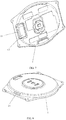
- the present embodiment provides a horn mounting structure for an electronic device, including a shell 1, a holder 3 and a horn 4, the shell 1 (see FIG. 7 and FIG. 8 ) is a metal shell processed through CNC; a sound hole 11 is formed at a side surface of the shell 1 for achieving a side sounding function of the electronic device, to avoid influencing an appearance and a sounding effect of the electronic device when the sound hole 11 is formed in an upper surface or a lower surface of the shell 1.
- a mounting groove 12 is formed at a position in an inner part of the shell 1 that is close to a side surface of the shell 1; and the sound hole 11 is communicated with the mounting groove 12, so as to transmit the sound made by the horn 4 arranged in the mounting groove 12 to an outer part of the electronic device.
- the holder 3 is mounted in the mounting groove 12, and an outline dimension of the holder 3 is matched with that of the mounting groove 12, so as to increase the mounting stability of the holder 3 and the structural compactness of the shell 1.
- the holder 3 is bonded in the mounting groove 12 through a sealant.
- the sealant is adopted for connection, thereby not only guaranteeing the fixing reliability between the holder 3 and the shell 1, but also greatly improving the leakproofness of a junction between the holder 3 and the shell 1 and preventing water leakage.
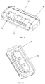
- a front sound chamber 33 is formed at one side of the holder 3 (see FIG. 9 and FIG. 10 ), which faces to the sound hole 11 and enables that the sound hole 11 is communicated with the horn 4, so as to achieve the side sounding function of the electronic device.
- the horn 4 is mounted in the holder 3, and in an embodiment, the horn 4 is bonded at one side of the holder 3 facing to the inside of the shell 1 through the sealant.
- connection manner also guarantees the fixing reliability between the horn 4 and the holder 3, and effectively improves the sealing effect between the horn 4 and the holder 3.
- the sealant used in the present embodiment is curable liquid glue, so as to achieve the sealing and fixing effects.
- the horn mounting structure in the present embodiment could achieve higher waterproof level and more durable waterproof effect.
- the horn mounting structure also has better weather fastness and corrosion resistance. Through tests, the horn mounting structure of the present embodiment has waterproofness above IPX8.
- the holder 3 is bonded in the mounting groove 12 of the shell 1, and the horn 4 is bonded on the holder 4, thereby guaranteeing the sealing connection between the holder 3 and the shell 1 and between the horn 4 and the holder 3 on the basis of achieving the side sounding function of the shell 1, effectively improving the waterproof reliability of the electronic device, and solving the problems that a plastic material and the metal material have poor bonding reliability in the horn mounting structure and the water leakage is easily generated at a joint in the related art.
- the shell 1, the holder 3 and other structures of the present embodiment could be separately produced and then assembled, thereby reducing the processing and assembly difficulties of the horn mounting structure, reducing the production cost, and solving the problems of complicated processing of the metal shell and high cost caused by direct processing of the horn mounting structure on the shell 1 in the existing art.
- the horn mounting structure of the present embodiment as an independent assembly module, avoids a matching relationship with other structures having a waterproof demand in the shell 1, thereby reducing the complexity of a waterproof structure of the shell 1, and improving the waterproof ability and production convenience of the shell 1.
- a dustproof net 2 is further arranged between the sound hole 11 and the front sound chamber 33, for preventing impurities such as dust from entering into the front sound chamber 33, thereby preventing the dust from influencing normal work of the horn 4.
- the dustproof net 2 is connected with the shell 1 and the holder 3 respectively by a gluing way, thereby simplifying the mounting process of the dustproof net 2and increasing the assembly efficiency of the shell 1.
- FIG. 6 shows that shows that is connected with the shell 1 and the holder 3 respectively by a gluing way, thereby simplifying the mounting process of the dustproof net 2and increasing the assembly efficiency of the shell 1.
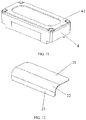
- the dustproof net 2 has a bending shape, and includes a first connecting portion 21, a dustproof portion 22 and a second connecting portion 23 which are successively connected, the first connecting portion 21 is arranged between a bottom of the mounting groove 12 and a top 37 of the holder 3, the dustproof portion 22 is arranged at the sound hole 11, and the second connecting portion 23 is arranged between a side surface of the mounting grove 12 and a side surface of the holder 3. As shown in FIG. 2 and FIG.
- one side of dustproof net 2 for instance, one side of the first connecting portion 21 is bonded with a bottom of the mounting groove 12 through a first bonding layer 5, and a shape of the cured first bonding layer 5 is a rectangle; the edge of the second side of the dustproof net 2 is bonded with the holder 3 through a second bonding layer 6, and a bonding position of dustproof net 2 includes edges of the first connecting portion 21, the dustproof portion 22 and the second connecting portion 23.
- a circle of first connecting surface 31 (see FIG. 9 ) is formed around the front sound chamber 33 at the top 37 of the holder 3, the dustproof net 2 is bonded with the first connecting surface 31 through the second bonding layer 6, and a shape of the cured second bonding layer 6 is the same as that of the first connecting surface 31, so as to achieve firm connection between the holder 3 and the dustproof net 2, and prevent a gluing layer from influencing the sounding of the horn 4.
- the first connecting portion 21 and the dustproof portion 22 may connected to each other through the second bonding layer 6.
- the dustproof net 2 could be made of materials having dustproof and ventilation functions, such as cloth materials; and the dustproof net 2 could be bonded with the shell 1 and the holder 3 by gluing when mounting; a two-sided glue could also be arranged at both sides of the dustproof net 2, and when mounting, the dustproof net 2 is directly connected with the shell 1 and the holder 3 by removing the two-sided glue, and such mounting process is more simple and fast, thereby greatly increasing the assembly efficiency of the shell 1.
- a plurality of division plates 32 are also arranged at the top 37 of the holder 3.
- Each of the division plates 32 divides an internal space of the holder 3 into a plurality of front sound chambers 33, which are communicated with each other.
- the structural strength of the holder 3 is increased, and meanwhile, a certain supporting role can be played for the dustproof net 2, thereby preventing the deformation of the dustproof net 2.
- the holder 3 of the present embodiment is preferably formed integrally by plastic materials.
- reinforcing ribs 34 are further arranged at the top of the holder 3, to achieve the effect of improving the structural strength of the holder 3, improving the processing technology of the holder 3 and preventing shrinkage and other defects.
- an outer side of the side wall of the holder 3 is bonded with an inner side of the mounting groove 12 through a third bonding layer 7, and the third bonding layer 7 is a sealant layer, so as to guarantee the sealing performance between the holder 3 and the mounting groove 12, and prevent water leakage at the junction of the holder 3 and the mounting groove 12.
- an oblong through hole 35 is further formed at the bottom of the holder 3, for communicating the front sound chambers 33 with the horn 4; and a circle of annular groove 36 is formed along a periphery of the through hole 35, for mounting the horn 4.
- a second connecting surface is formed in the groove 36, a third connecting surface 41 is formed at the top of the horn 4 (see FIG. 11 ), the second connecting surface is bonded with the third connecting surface 41 through a fourth bonding layer 8, and herein, the fourth bonding layer 8 is also a sealant layer, to achieve the waterproof sealing between the holder 3 and the horn 4.
- the horn mounting structure of the present embodiment takes a dash line in the figure as a boundary; a region above the dash line is communicated with the outer part of the shell 1 and is a non-waterproof region; and a region below the dash line is communicated with the inner part of the shell 1 and is a waterproof region, thereby effectively preventing water from entering into the shell from the sound hole 11, and guaranteeing safe operation of internal components of the electronic device.
- the first bonding layer 5 and the second bonding layer 6 in the present embodiment could also be the sealant layers, so as to further increase the waterproof capability of the horn mounting structure.
- the present embodiment further provides an electronic device, including the above horn mounting structure.
- the electronic device is an electronic watch, a sports bracelet, a mobile phone or a tablet computer.
- the present embodiment guarantees the sealing connection between the shell and the horn and effectively improving the waterproof reliability of the electronic device, on the basis of achieving the side sounding function of the shell. Meanwhile, when the horn is mounted, a common standard horn could be selected to achieve the waterproof function of the whole machine, without specially customizing a horn having a special structure, thereby simplifying the manufacturing process of the electronic device, reducing the processing and assembly difficulties of the horn mounting structure and saving the production cost.
- a horn mounting structure provided by the present application ensures the sealing connection between the holder and the shell and between the horn and the holder on the basis of achieving a side sounding function of the shell, thereby effectively improving waterproof reliability of the electronic device, and solving problems that a plastic material and the metal material have poor bonding reliability in the existing horn mounting structure and the water leakage is easily generated at a joint.
Landscapes
- Engineering & Computer Science (AREA)
- Physics & Mathematics (AREA)
- Signal Processing (AREA)
- Acoustics & Sound (AREA)
- Theoretical Computer Science (AREA)
- Computer Hardware Design (AREA)
- General Engineering & Computer Science (AREA)
- General Physics & Mathematics (AREA)
- Human Computer Interaction (AREA)
- Microelectronics & Electronic Packaging (AREA)
- Health & Medical Sciences (AREA)
- Otolaryngology (AREA)
- Telephone Set Structure (AREA)
- Details Of Audible-Bandwidth Transducers (AREA)
- Details Of Aerials (AREA)
- Casings For Electric Apparatus (AREA)
Abstract
Description
- The present disclosure relates to the technical field of electronic devices, and for example to a horn mounting structure and an electronic device having same.
- In a small electronic device, such as a watch or a wristband, in order to facilitate sounding of a horn and saving space occupation of a horn, a sound hole of the device is usually formed at a side surface of a metal shell. When the horn and the metal shell are assembled, the following two solutions are usually adopted in a related art.
- Firstly, the metal shell is placed in a mold; then, an internal assembly structure is molded in the metal shell by a nano injection molding process; and later, the horn is mounted in the internal assembly structure. However, for the electronic device prepared with such process, an injection molding material and a metal material have poor physical associativity, causing that the junction between the internal assembly structure and the metal shell has poor waterproof reliability, and more defective products with water leakage would be presented during mass production.
- The internal assembly structure is processed on the metal shell directly using a Computer numerical control (CNC) processing technology, and then, the horn is mounted in the internal assembly structure. However, it may increase the processing difficulty of the metal shell and greatly increase the processing cost of the metal shell that an internal structure for assembling the horn is directly processed on the metal shell. Meanwhile, for small products having tiny structures, such as the watch or the wristband, it would also be very difficult when a dustproof net or other structures are added in a subsequent procedure by virtue of such form of shell.
- Based on the above mentioned, the present disclosure provides a horn mounting structure and an electronic device having same, which may effectively improve the waterproof reliability of the electronic device, reduce the processing and assembly difficulties of the horn mounting structure and save production cost.
- A horn mounting structure includes: a shell; a holder, where a sound hole formed at a side surface of the shell; a mounting groove formed inside the shell; where the sound hole is communicated with the mounting groove, and the holder is bonded in the mounting groove through a sealant; a front sound chamber formed at one side of the holder facing to the sound hole; and a horn bonded to one side of the holder facing away from the shell through the sealant.
- In an embodiment, a dustproof net is further included, and the dustproof is arranged between the sound hole and the front sound chamber and is bonded with the shell and the holder respectively.
- In an embodiment, the dustproof net includes a first connecting portion, a dustproof portion and a second connecting portion which are successively connected; the first connecting portion is arranged between an inside bottom of the mounting groove and a top of the holder, the dustproof portion is arranged at the sound hole, and the second connecting portion is arranged between a side surface of the mounting grove and a side surface of the holder.
- In an embodiment, the inside bottom of mounting groove is bonded with the first connecting portion through a first bonding layer.
- In an embodiment, a first connecting surface is formed at the top of the holder, and the first connecting portion and the second connecting portion of the dustproof net are bonded with the first connecting surface through a second bonding layer.
- In an embodiment, a periphery of a side wall of the holder is bonded with the mounting groove through a third bonding layer.
- In an embodiment, the holder comprises a groove, and the groove is configured for mounting the horn; a second connecting surface is formed in the groove, a third connecting surface is formed at a first part of the horn, and the second connecting surface is bonded with the third connecting surface through a fourth bonding layer.
- In an embodiment, the third bonding layer and the fourth bonding layer are sealant layers. In an embodiment, at least one of the first bonding layer and the second bonding layer is a sealant layer.
- An electronic device includes the horn mounting structure in any solution above.
- In an embodiment, the electronic device is an electronic watch, a sports bracelet, a mobile phone or a tablet computer.
- An embodiment ensures the sealing connection between the holder and the shell and between the horn and the holder on the basis of achieving a side sounding function of the shell, thereby effectively improving waterproof reliability of the electronic device, and solving problems that a plastic material and the metal material have poor bonding reliability in the existing horn mounting structure and the water leakage is easily generated at a joint; and meanwhile, the shell, the holder and other structures of the present disclosure could be separately produced and then assembled, thereby reducing the processing and assembly difficulties of the horn mounting structure, reducing the production cost, and solving the problems of complicated processing of the metal shell and high cost caused by direct processing of the horn mounting structure on the shell in the existing art. In addition, the horn mounting structure of the present disclosure, as an independent assembly module, avoids a matching relationship with other structures having a waterproof demand in the shell, thereby reducing the complexity of a waterproof structure of the shell, and improving waterproof capability and production convenience of the shell.
-
-
FIG. 1 is an exploded diagram illustrating a horn mounting structure provided by an embodiment (a bonding layer is not shown); -
FIG. 2 is a exploded diagram illustrating a horn mounting structure provided by another embodiment (a bonding layer is shown); -
FIG. 3 is a schematic diagram ofFIG. 1 from another angle; -
FIG. 4 is a schematic diagram ofFIG. 2 from another angle; -
FIG. 5 is an assembly diagram illustrating a horn mounting structure provided by another embodiment; -
FIG. 6 is a partial section view illustrating a horn mounting structure provided by an embodiment; -
FIG. 7 is a structural diagram illustrating a shell involved in an embodiment; -
FIG. 8 is schematic diagram ofFIG. 7 from another angle; -
FIG. 9 is a structural diagram illustrating a holder involved in an embodiment; -
FIG. 10 is schematic diagram ofFIG. 9 from another angle; -
FIG. 11 is a structural diagram illustrating a horn involved in an embodiment; and -
FIG. 12 is a structural diagram illustrating a dustproof net involved in an embodiment. - In the figures:
- 1-Shell; 11-Sound hole; 12-Mounting groove;
- 2-Dustproof net; 21-First connecting portion; 22-Dustproof portion; 23-Second connecting portion;
- 3-Holder; 31-First connecting surface; 32-Division plate; 33-Front sound chamber; 34-Reinforcing rib; 35-Through hole; 36-Groove;
- 4-Horn; 41-Third connecting surface;
- 5-First bonding layer; 6-Second bonding layer; 7-Third bonding layer; and 8-Fourth bonding layer.
- The "top" in the prevent disclosure refers to one side close to an outer part of the shell in a corresponding component, and the "bottom" refers to one side close to an inner part of the shell in the corresponding component.
- As shown in
FIG. 1 ,FIG. 3 andFIG. 5 , the present embodiment provides a horn mounting structure for an electronic device, including ashell 1, aholder 3 and ahorn 4, the shell 1 (seeFIG. 7 and FIG. 8 ) is a metal shell processed through CNC; asound hole 11 is formed at a side surface of theshell 1 for achieving a side sounding function of the electronic device, to avoid influencing an appearance and a sounding effect of the electronic device when thesound hole 11 is formed in an upper surface or a lower surface of theshell 1. Amounting groove 12 is formed at a position in an inner part of theshell 1 that is close to a side surface of theshell 1; and thesound hole 11 is communicated with themounting groove 12, so as to transmit the sound made by thehorn 4 arranged in themounting groove 12 to an outer part of the electronic device. Theholder 3 is mounted in themounting groove 12, and an outline dimension of theholder 3 is matched with that of themounting groove 12, so as to increase the mounting stability of theholder 3 and the structural compactness of theshell 1. Optionally, theholder 3 is bonded in themounting groove 12 through a sealant. The sealant is adopted for connection, thereby not only guaranteeing the fixing reliability between theholder 3 and theshell 1, but also greatly improving the leakproofness of a junction between theholder 3 and theshell 1 and preventing water leakage. In addition, afront sound chamber 33 is formed at one side of the holder 3 (seeFIG. 9 and FIG. 10 ), which faces to thesound hole 11 and enables that thesound hole 11 is communicated with thehorn 4, so as to achieve the side sounding function of the electronic device. Thehorn 4 is mounted in theholder 3, and in an embodiment, thehorn 4 is bonded at one side of theholder 3 facing to the inside of theshell 1 through the sealant. Such connection manner also guarantees the fixing reliability between thehorn 4 and theholder 3, and effectively improves the sealing effect between thehorn 4 and theholder 3. Herein, the sealant used in the present embodiment is curable liquid glue, so as to achieve the sealing and fixing effects. Compared with a waterproof double-sided adhesive tape and a waterproof cotton adhesive tape, the horn mounting structure in the present embodiment could achieve higher waterproof level and more durable waterproof effect. Meanwhile, the horn mounting structure also has better weather fastness and corrosion resistance. Through tests, the horn mounting structure of the present embodiment has waterproofness above IPX8. - In the present embodiment, through the sealant, the
holder 3 is bonded in themounting groove 12 of theshell 1, and thehorn 4 is bonded on theholder 4, thereby guaranteeing the sealing connection between theholder 3 and theshell 1 and between thehorn 4 and theholder 3 on the basis of achieving the side sounding function of theshell 1, effectively improving the waterproof reliability of the electronic device, and solving the problems that a plastic material and the metal material have poor bonding reliability in the horn mounting structure and the water leakage is easily generated at a joint in the related art. Meanwhile, theshell 1, theholder 3 and other structures of the present embodiment could be separately produced and then assembled, thereby reducing the processing and assembly difficulties of the horn mounting structure, reducing the production cost, and solving the problems of complicated processing of the metal shell and high cost caused by direct processing of the horn mounting structure on theshell 1 in the existing art. In addition, the horn mounting structure of the present embodiment, as an independent assembly module, avoids a matching relationship with other structures having a waterproof demand in theshell 1, thereby reducing the complexity of a waterproof structure of theshell 1, and improving the waterproof ability and production convenience of theshell 1. - Further, as shown in
FIG. 6 , adustproof net 2 is further arranged between thesound hole 11 and thefront sound chamber 33, for preventing impurities such as dust from entering into thefront sound chamber 33, thereby preventing the dust from influencing normal work of thehorn 4. In one embodiment, thedustproof net 2 is connected with theshell 1 and theholder 3 respectively by a gluing way, thereby simplifying the mounting process of the dustproof net 2and increasing the assembly efficiency of theshell 1. In one embodiment, as shown inFIG. 12 , thedustproof net 2 has a bending shape, and includes a first connectingportion 21, adustproof portion 22 and a second connectingportion 23 which are successively connected, the first connectingportion 21 is arranged between a bottom of the mountinggroove 12 and a top 37 of theholder 3, thedustproof portion 22 is arranged at thesound hole 11, and the second connectingportion 23 is arranged between a side surface of the mountinggrove 12 and a side surface of theholder 3. As shown inFIG. 2 andFIG. 4 , one side ofdustproof net 2, for instance, one side of the first connectingportion 21 is bonded with a bottom of the mountinggroove 12 through afirst bonding layer 5, and a shape of the curedfirst bonding layer 5 is a rectangle; the edge of the second side of thedustproof net 2 is bonded with theholder 3 through asecond bonding layer 6, and a bonding position ofdustproof net 2 includes edges of the first connectingportion 21, thedustproof portion 22 and the second connectingportion 23. - In an embodiment, a circle of first connecting surface 31 (see
FIG. 9 ) is formed around thefront sound chamber 33 at the top 37 of theholder 3, thedustproof net 2 is bonded with the first connectingsurface 31 through thesecond bonding layer 6, and a shape of the curedsecond bonding layer 6 is the same as that of the first connectingsurface 31, so as to achieve firm connection between theholder 3 and thedustproof net 2, and prevent a gluing layer from influencing the sounding of thehorn 4. In an embodiment, the first connectingportion 21 and thedustproof portion 22 may connected to each other through thesecond bonding layer 6. - In the present embodiment, the
dustproof net 2 could be made of materials having dustproof and ventilation functions, such as cloth materials; and thedustproof net 2 could be bonded with theshell 1 and theholder 3 by gluing when mounting; a two-sided glue could also be arranged at both sides of thedustproof net 2, and when mounting, thedustproof net 2 is directly connected with theshell 1 and theholder 3 by removing the two-sided glue, and such mounting process is more simple and fast, thereby greatly increasing the assembly efficiency of theshell 1. - Further, as shown in
FIG. 9 , a plurality ofdivision plates 32 are also arranged at the top 37 of theholder 3. Each of thedivision plates 32 divides an internal space of theholder 3 into a plurality offront sound chambers 33, which are communicated with each other. Through such arrangement, the structural strength of theholder 3 is increased, and meanwhile, a certain supporting role can be played for thedustproof net 2, thereby preventing the deformation of thedustproof net 2. In addition, to facilitate the processing and save manufacturing cost, theholder 3 of the present embodiment is preferably formed integrally by plastic materials. Meanwhile, reinforcingribs 34 are further arranged at the top of theholder 3, to achieve the effect of improving the structural strength of theholder 3, improving the processing technology of theholder 3 and preventing shrinkage and other defects. - In the present embodiment, an outer side of the side wall of the
holder 3 is bonded with an inner side of the mountinggroove 12 through athird bonding layer 7, and thethird bonding layer 7 is a sealant layer, so as to guarantee the sealing performance between theholder 3 and the mountinggroove 12, and prevent water leakage at the junction of theholder 3 and the mountinggroove 12. As shown inFIG. 10 , an oblong throughhole 35 is further formed at the bottom of theholder 3, for communicating thefront sound chambers 33 with thehorn 4; and a circle ofannular groove 36 is formed along a periphery of the throughhole 35, for mounting thehorn 4. In one embodiment, a second connecting surface is formed in thegroove 36, a third connectingsurface 41 is formed at the top of the horn 4 (seeFIG. 11 ), the second connecting surface is bonded with the third connectingsurface 41 through afourth bonding layer 8, and herein, thefourth bonding layer 8 is also a sealant layer, to achieve the waterproof sealing between theholder 3 and thehorn 4. Through the above arrangement, as shown inFIG. 6 , the horn mounting structure of the present embodiment takes a dash line in the figure as a boundary; a region above the dash line is communicated with the outer part of theshell 1 and is a non-waterproof region; and a region below the dash line is communicated with the inner part of theshell 1 and is a waterproof region, thereby effectively preventing water from entering into the shell from thesound hole 11, and guaranteeing safe operation of internal components of the electronic device. Thefirst bonding layer 5 and thesecond bonding layer 6 in the present embodiment could also be the sealant layers, so as to further increase the waterproof capability of the horn mounting structure. - The present embodiment further provides an electronic device, including the above horn mounting structure. In an embodiment, the electronic device is an electronic watch, a sports bracelet, a mobile phone or a tablet computer. The present embodiment guarantees the sealing connection between the shell and the horn and effectively improving the waterproof reliability of the electronic device, on the basis of achieving the side sounding function of the shell. Meanwhile, when the horn is mounted, a common standard horn could be selected to achieve the waterproof function of the whole machine, without specially customizing a horn having a special structure, thereby simplifying the manufacturing process of the electronic device, reducing the processing and assembly difficulties of the horn mounting structure and saving the production cost.
- A horn mounting structure provided by the present application ensures the sealing connection between the holder and the shell and between the horn and the holder on the basis of achieving a side sounding function of the shell, thereby effectively improving waterproof reliability of the electronic device, and solving problems that a plastic material and the metal material have poor bonding reliability in the existing horn mounting structure and the water leakage is easily generated at a joint.
Claims (11)
- A horn mounting structure, comprising:a shell (1), wherein a sound hole (11) is formed at a side surface of the shell (1);a mounting groove (12) formed inside the shell (1), wherein the sound hole (11) is communicated with the mounting groove (12);a holder (3), wherein the holder (3) is bonded in the mounting groove (12) through a sealant, and a front sound chamber (33) is formed at one side of the holder (3) facing to the sound hole (11), anda horn (4), wherein the horn (4) is bonded to one side of the holder (3) facing away from the shell (1) through the sealant.
- The horn mounting structure according to claim 1, further comprising a dustproof net (2);
wherein the dustproof net (2) is arranged between the sound hole (11) and the front sound chamber (33), and is bonded with the shell (1) and the holder (3) respectively. - The horn mounting structure according to claim 2, wherein the dustproof net (2) comprises a first connecting portion (21), a dustproof portion (22) and a second connecting portion (23) which are successively connected;
wherein the first connecting portion (21) is arranged between an inside bottom of the mounting groove (12) and a top (37) of the holder (3), the dustproof portion (22) is arranged at the sound hole (11), and the second connecting portion (23) is arranged between a side surface of the mounting grove (12) and a side surface of the holder (3). - The horn mounting structure according to claim 3, wherein the inside bottom of mounting groove (12) is bonded with the first connecting portion (21) through a first bonding layer (5).
- The horn mounting structure according to claim 4, wherein a first connecting surface (31) is formed at the top (37) of the holder (3), and the first connecting portion (21) and the second connecting portion (23) of the dustproof net (2) are bonded with the first connecting surface (31) through a second bonding layer (6).
- The horn mounting structure according to claim 5, wherein a periphery of a side wall of the holder (3) is bonded with the mounting groove (12) through a third bonding layer (7).
- The horn mounting structure according to claim 6, wherein the holder (3) comprises a groove (36), and the groove (36) is configured for mounting the horn (4); a second connecting surface (361) is formed in the groove (36), a third connecting surface (41) is formed at a first part of the horn (4), and the second connecting surface (361) is bonded with the third connecting surface (41) through a fourth bonding layer (8).
- The horn mounting structure according to claim 7, wherein the third bonding layer (7) and the fourth bonding layer (8) are sealant layers.
- The horn mounting structure according to claim 5, wherein at least one of the first bonding layer (5) and the second bonding layer (6) is a sealant layer.
- An electronic device, comprising the horn mounting structure according to any one of claims 1-9.
- The electronic device according to claim 10, comprising an electronic watch, a sports bracelet, a mobile phone or a tablet computer.
Applications Claiming Priority (2)
| Application Number | Priority Date | Filing Date | Title |
|---|---|---|---|
| CN201810069346.5A CN108260059B (en) | 2018-01-24 | 2018-01-24 | Loudspeaker mounting structure and have its electronic equipment |
| PCT/CN2018/087467 WO2019144539A1 (en) | 2018-01-24 | 2018-05-18 | Speaker mounting structure and electronic device provided with same |
Publications (3)
| Publication Number | Publication Date |
|---|---|
| EP3745742A1 true EP3745742A1 (en) | 2020-12-02 |
| EP3745742A4 EP3745742A4 (en) | 2021-10-13 |
| EP3745742B1 EP3745742B1 (en) | 2022-12-28 |
Family
ID=62743015
Family Applications (1)
| Application Number | Title | Priority Date | Filing Date |
|---|---|---|---|
| EP18723657.5A Active EP3745742B1 (en) | 2018-01-24 | 2018-05-18 | Speaker mounting structure and electronic device provided with same |
Country Status (4)
| Country | Link |
|---|---|
| US (1) | US11290808B2 (en) |
| EP (1) | EP3745742B1 (en) |
| CN (1) | CN108260059B (en) |
| WO (1) | WO2019144539A1 (en) |
Families Citing this family (3)
| Publication number | Priority date | Publication date | Assignee | Title |
|---|---|---|---|---|
| CN112468943B (en) * | 2019-09-06 | 2022-04-29 | 瑞声科技(新加坡)有限公司 | Loudspeaker structure and electronic equipment applying same |
| CN114585209B (en) * | 2020-11-30 | 2022-12-20 | 荣耀终端有限公司 | Electronic equipment frame |
| US20240149429A1 (en) * | 2024-01-15 | 2024-05-09 | Jonathan Adams | Mag-Mount |
Family Cites Families (11)
| Publication number | Priority date | Publication date | Assignee | Title |
|---|---|---|---|---|
| JP2001197182A (en) * | 2000-01-05 | 2001-07-19 | Nec Saitama Ltd | Receiving system and method for portable telephone set |
| JP4002561B2 (en) * | 2004-06-30 | 2007-11-07 | 埼玉日本電気株式会社 | Small speaker mounting structure in portable electronic device and portable electronic device having the structure |
| US20070223744A1 (en) * | 2006-03-23 | 2007-09-27 | Epson Imaging Devices Corporation | Electro-optic device and electronic apparatus |
| CN202085292U (en) * | 2011-03-07 | 2011-12-21 | 海能达通信股份有限公司 | Audio cavity device |
| CN202931405U (en) * | 2012-11-01 | 2013-05-08 | 深圳天珑无线科技有限公司 | Mobile phone and speaker device thereof |
| CN203590383U (en) * | 2013-09-12 | 2014-05-07 | 歌尔声学股份有限公司 | Loudspeaker module |
| CN204795478U (en) * | 2015-07-09 | 2015-11-18 | 上海与德通讯技术有限公司 | Loudspeaker module and electronic equipment |
| CN106101947B (en) * | 2016-06-20 | 2019-01-15 | Oppo广东移动通信有限公司 | Loudspeaker go out acoustic form and mobile terminal |
| CN206341406U (en) * | 2016-11-13 | 2017-07-18 | 上海与德信息技术有限公司 | Electronic equipment |
| CN106686506A (en) * | 2017-02-24 | 2017-05-17 | 上海与德信息技术有限公司 | Loudspeaker |
| CN107528944B (en) * | 2017-09-08 | 2025-06-10 | 北京小米移动软件有限公司 | Communications equipment |
-
2018
- 2018-01-24 CN CN201810069346.5A patent/CN108260059B/en active Active
- 2018-05-18 EP EP18723657.5A patent/EP3745742B1/en active Active
- 2018-05-18 US US15/778,981 patent/US11290808B2/en active Active
- 2018-05-18 WO PCT/CN2018/087467 patent/WO2019144539A1/en not_active Ceased
Also Published As
| Publication number | Publication date |
|---|---|
| US11290808B2 (en) | 2022-03-29 |
| CN108260059A (en) | 2018-07-06 |
| EP3745742B1 (en) | 2022-12-28 |
| EP3745742A4 (en) | 2021-10-13 |
| US20210266660A1 (en) | 2021-08-26 |
| WO2019144539A1 (en) | 2019-08-01 |
| CN108260059B (en) | 2020-04-10 |
Similar Documents
| Publication | Publication Date | Title |
|---|---|---|
| JP6460633B2 (en) | Electronic device including a camera module | |
| KR20160086385A (en) | Speaker Module and Manufacturing Method Therefor | |
| EP3745742B1 (en) | Speaker mounting structure and electronic device provided with same | |
| CN107660095A (en) | The seal member and its manufacture method of mobile terminal | |
| WO2016176981A1 (en) | Loudspeaker module | |
| CN118870859B (en) | Display panel, manufacturing method and display terminal | |
| CN104936109B (en) | Microspeaker | |
| CN204810544U (en) | Loudspeaker | |
| CN108965668A (en) | A mobile terminal and camera module of the mobile terminal | |
| CN113037894A (en) | Electronic equipment | |
| CN108810678B (en) | Mobile terminal | |
| CN114025525B (en) | Shell assembly and electronic equipment | |
| CN208063455U (en) | Loud speaker module | |
| CN205945948U (en) | Two camera subassemblies | |
| CN107786694A (en) | Fingerprint identification module and its assembly method, housing assembly and electronic device | |
| TWI626158B (en) | Case structure of electronic device and manufacturing method thereof | |
| CN204733373U (en) | Microspeaker | |
| CN115118839A (en) | Camera module and electronic device | |
| CN207783150U (en) | A kind of loudspeaker installation structure and the electronic equipment with it | |
| CN206820997U (en) | Housing, loudspeaker module and electronic equipment for loudspeaker module | |
| CN206100435U (en) | Speaker module casing, speaker module and sound generating mechanism | |
| WO2020258892A1 (en) | Fingerprint module and display device | |
| CN112297544A (en) | Preparation method of ceramic shell, ceramic shell and electronic equipment | |
| WO2015159518A1 (en) | Electronic device and manufacturing method for case therefor | |
| JP2016522583A (en) | Battery housing assembly, plastic metal assembly and plastic member for electronic equipment |
Legal Events
| Date | Code | Title | Description |
|---|---|---|---|
| STAA | Information on the status of an ep patent application or granted ep patent |
Free format text: STATUS: UNKNOWN |
|
| STAA | Information on the status of an ep patent application or granted ep patent |
Free format text: STATUS: THE INTERNATIONAL PUBLICATION HAS BEEN MADE |
|
| PUAI | Public reference made under article 153(3) epc to a published international application that has entered the european phase |
Free format text: ORIGINAL CODE: 0009012 |
|
| STAA | Information on the status of an ep patent application or granted ep patent |
Free format text: STATUS: REQUEST FOR EXAMINATION WAS MADE |
|
| 17P | Request for examination filed |
Effective date: 20180524 |
|
| AK | Designated contracting states |
Kind code of ref document: A1 Designated state(s): AL AT BE BG CH CY CZ DE DK EE ES FI FR GB GR HR HU IE IS IT LI LT LU LV MC MK MT NL NO PL PT RO RS SE SI SK SM TR |
|
| AX | Request for extension of the european patent |
Extension state: BA ME |
|
| DAV | Request for validation of the european patent (deleted) | ||
| DAX | Request for extension of the european patent (deleted) | ||
| A4 | Supplementary search report drawn up and despatched |
Effective date: 20210915 |
|
| RIC1 | Information provided on ipc code assigned before grant |
Ipc: H04M 1/18 20060101ALI20210909BHEP Ipc: H04M 1/03 20060101ALI20210909BHEP Ipc: H04R 1/30 20060101ALI20210909BHEP Ipc: H04R 1/02 20060101ALI20210909BHEP Ipc: H05K 5/06 20060101ALI20210909BHEP Ipc: H04R 9/02 20060101ALI20210909BHEP Ipc: H04M 1/02 20060101ALI20210909BHEP Ipc: H04R 9/06 20060101AFI20210909BHEP |
|
| GRAP | Despatch of communication of intention to grant a patent |
Free format text: ORIGINAL CODE: EPIDOSNIGR1 |
|
| STAA | Information on the status of an ep patent application or granted ep patent |
Free format text: STATUS: GRANT OF PATENT IS INTENDED |
|
| INTG | Intention to grant announced |
Effective date: 20220720 |
|
| GRAS | Grant fee paid |
Free format text: ORIGINAL CODE: EPIDOSNIGR3 |
|
| GRAA | (expected) grant |
Free format text: ORIGINAL CODE: 0009210 |
|
| STAA | Information on the status of an ep patent application or granted ep patent |
Free format text: STATUS: THE PATENT HAS BEEN GRANTED |
|
| AK | Designated contracting states |
Kind code of ref document: B1 Designated state(s): AL AT BE BG CH CY CZ DE DK EE ES FI FR GB GR HR HU IE IS IT LI LT LU LV MC MK MT NL NO PL PT RO RS SE SI SK SM TR |
|
| REG | Reference to a national code |
Ref country code: GB Ref legal event code: FG4D |
|
| REG | Reference to a national code |
Ref country code: CH Ref legal event code: EP |
|
| REG | Reference to a national code |
Ref country code: DE Ref legal event code: R096 Ref document number: 602018044706 Country of ref document: DE |
|
| REG | Reference to a national code |
Ref country code: AT Ref legal event code: REF Ref document number: 1541222 Country of ref document: AT Kind code of ref document: T Effective date: 20230115 |
|
| REG | Reference to a national code |
Ref country code: IE Ref legal event code: FG4D |
|
| REG | Reference to a national code |
Ref country code: LT Ref legal event code: MG9D |
|
| PG25 | Lapsed in a contracting state [announced via postgrant information from national office to epo] |
Ref country code: SE Free format text: LAPSE BECAUSE OF FAILURE TO SUBMIT A TRANSLATION OF THE DESCRIPTION OR TO PAY THE FEE WITHIN THE PRESCRIBED TIME-LIMIT Effective date: 20221228 Ref country code: NO Free format text: LAPSE BECAUSE OF FAILURE TO SUBMIT A TRANSLATION OF THE DESCRIPTION OR TO PAY THE FEE WITHIN THE PRESCRIBED TIME-LIMIT Effective date: 20230328 Ref country code: LT Free format text: LAPSE BECAUSE OF FAILURE TO SUBMIT A TRANSLATION OF THE DESCRIPTION OR TO PAY THE FEE WITHIN THE PRESCRIBED TIME-LIMIT Effective date: 20221228 Ref country code: FI Free format text: LAPSE BECAUSE OF FAILURE TO SUBMIT A TRANSLATION OF THE DESCRIPTION OR TO PAY THE FEE WITHIN THE PRESCRIBED TIME-LIMIT Effective date: 20221228 |
|
| REG | Reference to a national code |
Ref country code: NL Ref legal event code: MP Effective date: 20221228 |
|
| REG | Reference to a national code |
Ref country code: AT Ref legal event code: MK05 Ref document number: 1541222 Country of ref document: AT Kind code of ref document: T Effective date: 20221228 |
|
| PG25 | Lapsed in a contracting state [announced via postgrant information from national office to epo] |
Ref country code: RS Free format text: LAPSE BECAUSE OF FAILURE TO SUBMIT A TRANSLATION OF THE DESCRIPTION OR TO PAY THE FEE WITHIN THE PRESCRIBED TIME-LIMIT Effective date: 20221228 Ref country code: LV Free format text: LAPSE BECAUSE OF FAILURE TO SUBMIT A TRANSLATION OF THE DESCRIPTION OR TO PAY THE FEE WITHIN THE PRESCRIBED TIME-LIMIT Effective date: 20221228 Ref country code: HR Free format text: LAPSE BECAUSE OF FAILURE TO SUBMIT A TRANSLATION OF THE DESCRIPTION OR TO PAY THE FEE WITHIN THE PRESCRIBED TIME-LIMIT Effective date: 20221228 Ref country code: GR Free format text: LAPSE BECAUSE OF FAILURE TO SUBMIT A TRANSLATION OF THE DESCRIPTION OR TO PAY THE FEE WITHIN THE PRESCRIBED TIME-LIMIT Effective date: 20230329 |
|
| PG25 | Lapsed in a contracting state [announced via postgrant information from national office to epo] |
Ref country code: NL Free format text: LAPSE BECAUSE OF FAILURE TO SUBMIT A TRANSLATION OF THE DESCRIPTION OR TO PAY THE FEE WITHIN THE PRESCRIBED TIME-LIMIT Effective date: 20221228 |
|
| PG25 | Lapsed in a contracting state [announced via postgrant information from national office to epo] |
Ref country code: SM Free format text: LAPSE BECAUSE OF FAILURE TO SUBMIT A TRANSLATION OF THE DESCRIPTION OR TO PAY THE FEE WITHIN THE PRESCRIBED TIME-LIMIT Effective date: 20221228 Ref country code: RO Free format text: LAPSE BECAUSE OF FAILURE TO SUBMIT A TRANSLATION OF THE DESCRIPTION OR TO PAY THE FEE WITHIN THE PRESCRIBED TIME-LIMIT Effective date: 20221228 Ref country code: PT Free format text: LAPSE BECAUSE OF FAILURE TO SUBMIT A TRANSLATION OF THE DESCRIPTION OR TO PAY THE FEE WITHIN THE PRESCRIBED TIME-LIMIT Effective date: 20230428 Ref country code: ES Free format text: LAPSE BECAUSE OF FAILURE TO SUBMIT A TRANSLATION OF THE DESCRIPTION OR TO PAY THE FEE WITHIN THE PRESCRIBED TIME-LIMIT Effective date: 20221228 Ref country code: EE Free format text: LAPSE BECAUSE OF FAILURE TO SUBMIT A TRANSLATION OF THE DESCRIPTION OR TO PAY THE FEE WITHIN THE PRESCRIBED TIME-LIMIT Effective date: 20221228 Ref country code: CZ Free format text: LAPSE BECAUSE OF FAILURE TO SUBMIT A TRANSLATION OF THE DESCRIPTION OR TO PAY THE FEE WITHIN THE PRESCRIBED TIME-LIMIT Effective date: 20221228 Ref country code: AT Free format text: LAPSE BECAUSE OF FAILURE TO SUBMIT A TRANSLATION OF THE DESCRIPTION OR TO PAY THE FEE WITHIN THE PRESCRIBED TIME-LIMIT Effective date: 20221228 |
|
| PG25 | Lapsed in a contracting state [announced via postgrant information from national office to epo] |
Ref country code: SK Free format text: LAPSE BECAUSE OF FAILURE TO SUBMIT A TRANSLATION OF THE DESCRIPTION OR TO PAY THE FEE WITHIN THE PRESCRIBED TIME-LIMIT Effective date: 20221228 Ref country code: PL Free format text: LAPSE BECAUSE OF FAILURE TO SUBMIT A TRANSLATION OF THE DESCRIPTION OR TO PAY THE FEE WITHIN THE PRESCRIBED TIME-LIMIT Effective date: 20221228 Ref country code: IS Free format text: LAPSE BECAUSE OF FAILURE TO SUBMIT A TRANSLATION OF THE DESCRIPTION OR TO PAY THE FEE WITHIN THE PRESCRIBED TIME-LIMIT Effective date: 20230428 Ref country code: AL Free format text: LAPSE BECAUSE OF FAILURE TO SUBMIT A TRANSLATION OF THE DESCRIPTION OR TO PAY THE FEE WITHIN THE PRESCRIBED TIME-LIMIT Effective date: 20221228 |
|
| REG | Reference to a national code |
Ref country code: DE Ref legal event code: R097 Ref document number: 602018044706 Country of ref document: DE |
|
| PG25 | Lapsed in a contracting state [announced via postgrant information from national office to epo] |
Ref country code: DK Free format text: LAPSE BECAUSE OF FAILURE TO SUBMIT A TRANSLATION OF THE DESCRIPTION OR TO PAY THE FEE WITHIN THE PRESCRIBED TIME-LIMIT Effective date: 20221228 |
|
| PLBE | No opposition filed within time limit |
Free format text: ORIGINAL CODE: 0009261 |
|
| STAA | Information on the status of an ep patent application or granted ep patent |
Free format text: STATUS: NO OPPOSITION FILED WITHIN TIME LIMIT |
|
| 26N | No opposition filed |
Effective date: 20230929 |
|
| REG | Reference to a national code |
Ref country code: CH Ref legal event code: PL |
|
| PG25 | Lapsed in a contracting state [announced via postgrant information from national office to epo] |
Ref country code: MC Free format text: LAPSE BECAUSE OF FAILURE TO SUBMIT A TRANSLATION OF THE DESCRIPTION OR TO PAY THE FEE WITHIN THE PRESCRIBED TIME-LIMIT Effective date: 20221228 |
|
| REG | Reference to a national code |
Ref country code: BE Ref legal event code: MM Effective date: 20230531 |
|
| PG25 | Lapsed in a contracting state [announced via postgrant information from national office to epo] |
Ref country code: SI Free format text: LAPSE BECAUSE OF FAILURE TO SUBMIT A TRANSLATION OF THE DESCRIPTION OR TO PAY THE FEE WITHIN THE PRESCRIBED TIME-LIMIT Effective date: 20221228 Ref country code: MC Free format text: LAPSE BECAUSE OF FAILURE TO SUBMIT A TRANSLATION OF THE DESCRIPTION OR TO PAY THE FEE WITHIN THE PRESCRIBED TIME-LIMIT Effective date: 20221228 Ref country code: LU Free format text: LAPSE BECAUSE OF NON-PAYMENT OF DUE FEES Effective date: 20230518 Ref country code: LI Free format text: LAPSE BECAUSE OF NON-PAYMENT OF DUE FEES Effective date: 20230531 Ref country code: CH Free format text: LAPSE BECAUSE OF NON-PAYMENT OF DUE FEES Effective date: 20230531 |
|
| REG | Reference to a national code |
Ref country code: IE Ref legal event code: MM4A |
|
| PG25 | Lapsed in a contracting state [announced via postgrant information from national office to epo] |
Ref country code: IE Free format text: LAPSE BECAUSE OF NON-PAYMENT OF DUE FEES Effective date: 20230518 |
|
| PG25 | Lapsed in a contracting state [announced via postgrant information from national office to epo] |
Ref country code: IE Free format text: LAPSE BECAUSE OF NON-PAYMENT OF DUE FEES Effective date: 20230518 |
|
| PG25 | Lapsed in a contracting state [announced via postgrant information from national office to epo] |
Ref country code: IT Free format text: LAPSE BECAUSE OF FAILURE TO SUBMIT A TRANSLATION OF THE DESCRIPTION OR TO PAY THE FEE WITHIN THE PRESCRIBED TIME-LIMIT Effective date: 20221228 Ref country code: BE Free format text: LAPSE BECAUSE OF NON-PAYMENT OF DUE FEES Effective date: 20230531 |
|
| PG25 | Lapsed in a contracting state [announced via postgrant information from national office to epo] |
Ref country code: BG Free format text: LAPSE BECAUSE OF FAILURE TO SUBMIT A TRANSLATION OF THE DESCRIPTION OR TO PAY THE FEE WITHIN THE PRESCRIBED TIME-LIMIT Effective date: 20221228 |
|
| PG25 | Lapsed in a contracting state [announced via postgrant information from national office to epo] |
Ref country code: BG Free format text: LAPSE BECAUSE OF FAILURE TO SUBMIT A TRANSLATION OF THE DESCRIPTION OR TO PAY THE FEE WITHIN THE PRESCRIBED TIME-LIMIT Effective date: 20221228 |
|
| PGFP | Annual fee paid to national office [announced via postgrant information from national office to epo] |
Ref country code: DE Payment date: 20250513 Year of fee payment: 8 |
|
| PGFP | Annual fee paid to national office [announced via postgrant information from national office to epo] |
Ref country code: GB Payment date: 20250521 Year of fee payment: 8 |
|
| PGFP | Annual fee paid to national office [announced via postgrant information from national office to epo] |
Ref country code: FR Payment date: 20250530 Year of fee payment: 8 |
|
| PG25 | Lapsed in a contracting state [announced via postgrant information from national office to epo] |
Ref country code: CY Free format text: LAPSE BECAUSE OF FAILURE TO SUBMIT A TRANSLATION OF THE DESCRIPTION OR TO PAY THE FEE WITHIN THE PRESCRIBED TIME-LIMIT; INVALID AB INITIO Effective date: 20180518 |
|
| PG25 | Lapsed in a contracting state [announced via postgrant information from national office to epo] |
Ref country code: HU Free format text: LAPSE BECAUSE OF FAILURE TO SUBMIT A TRANSLATION OF THE DESCRIPTION OR TO PAY THE FEE WITHIN THE PRESCRIBED TIME-LIMIT; INVALID AB INITIO Effective date: 20180518 |
|
| PG25 | Lapsed in a contracting state [announced via postgrant information from national office to epo] |
Ref country code: TR Free format text: LAPSE BECAUSE OF FAILURE TO SUBMIT A TRANSLATION OF THE DESCRIPTION OR TO PAY THE FEE WITHIN THE PRESCRIBED TIME-LIMIT Effective date: 20221228 |