EP3745531A1 - Antenna, bicycle, display device, and unmanned aerial vehicle - Google Patents
Antenna, bicycle, display device, and unmanned aerial vehicle Download PDFInfo
- Publication number
- EP3745531A1 EP3745531A1 EP19741953.4A EP19741953A EP3745531A1 EP 3745531 A1 EP3745531 A1 EP 3745531A1 EP 19741953 A EP19741953 A EP 19741953A EP 3745531 A1 EP3745531 A1 EP 3745531A1
- Authority
- EP
- European Patent Office
- Prior art keywords
- conductor
- antenna
- bicycle
- resonator
- unit
- Prior art date
- Legal status (The legal status is an assumption and is not a legal conclusion. Google has not performed a legal analysis and makes no representation as to the accuracy of the status listed.)
- Granted
Links
Images







































Classifications
-
- H—ELECTRICITY
- H01—ELECTRIC ELEMENTS
- H01Q—ANTENNAS, i.e. RADIO AERIALS
- H01Q15/00—Devices for reflection, refraction, diffraction or polarisation of waves radiated from an antenna, e.g. quasi-optical devices
- H01Q15/0006—Devices acting selectively as reflecting surface, as diffracting or as refracting device, e.g. frequency filtering or angular spatial filtering devices
- H01Q15/006—Selective devices having photonic band gap materials or materials of which the material properties are frequency dependent, e.g. perforated substrates, high-impedance surfaces
-
- A—HUMAN NECESSITIES
- A61—MEDICAL OR VETERINARY SCIENCE; HYGIENE
- A61B—DIAGNOSIS; SURGERY; IDENTIFICATION
- A61B5/00—Measuring for diagnostic purposes; Identification of persons
- A61B5/0059—Measuring for diagnostic purposes; Identification of persons using light, e.g. diagnosis by transillumination, diascopy, fluorescence
- A61B5/0077—Devices for viewing the surface of the body, e.g. camera, magnifying lens
-
- A—HUMAN NECESSITIES
- A61—MEDICAL OR VETERINARY SCIENCE; HYGIENE
- A61B—DIAGNOSIS; SURGERY; IDENTIFICATION
- A61B5/00—Measuring for diagnostic purposes; Identification of persons
- A61B5/02—Detecting, measuring or recording for evaluating the cardiovascular system, e.g. pulse, heart rate, blood pressure or blood flow
- A61B5/024—Measuring pulse rate or heart rate
- A61B5/02444—Details of sensor
-
- A—HUMAN NECESSITIES
- A61—MEDICAL OR VETERINARY SCIENCE; HYGIENE
- A61B—DIAGNOSIS; SURGERY; IDENTIFICATION
- A61B5/00—Measuring for diagnostic purposes; Identification of persons
- A61B5/05—Detecting, measuring or recording for diagnosis by means of electric currents or magnetic fields; Measuring using microwaves or radio waves
- A61B5/0507—Detecting, measuring or recording for diagnosis by means of electric currents or magnetic fields; Measuring using microwaves or radio waves using microwaves or terahertz waves
-
- B—PERFORMING OPERATIONS; TRANSPORTING
- B62—LAND VEHICLES FOR TRAVELLING OTHERWISE THAN ON RAILS
- B62J—CYCLE SADDLES OR SEATS; AUXILIARY DEVICES OR ACCESSORIES SPECIALLY ADAPTED TO CYCLES AND NOT OTHERWISE PROVIDED FOR, e.g. ARTICLE CARRIERS OR CYCLE PROTECTORS
- B62J45/00—Electrical equipment arrangements specially adapted for use as accessories on cycles, not otherwise provided for
- B62J45/20—Cycle computers as cycle accessories
-
- B—PERFORMING OPERATIONS; TRANSPORTING
- B62—LAND VEHICLES FOR TRAVELLING OTHERWISE THAN ON RAILS
- B62J—CYCLE SADDLES OR SEATS; AUXILIARY DEVICES OR ACCESSORIES SPECIALLY ADAPTED TO CYCLES AND NOT OTHERWISE PROVIDED FOR, e.g. ARTICLE CARRIERS OR CYCLE PROTECTORS
- B62J45/00—Electrical equipment arrangements specially adapted for use as accessories on cycles, not otherwise provided for
- B62J45/40—Sensor arrangements; Mounting thereof
- B62J45/41—Sensor arrangements; Mounting thereof characterised by the type of sensor
-
- B—PERFORMING OPERATIONS; TRANSPORTING
- B62—LAND VEHICLES FOR TRAVELLING OTHERWISE THAN ON RAILS
- B62J—CYCLE SADDLES OR SEATS; AUXILIARY DEVICES OR ACCESSORIES SPECIALLY ADAPTED TO CYCLES AND NOT OTHERWISE PROVIDED FOR, e.g. ARTICLE CARRIERS OR CYCLE PROTECTORS
- B62J45/00—Electrical equipment arrangements specially adapted for use as accessories on cycles, not otherwise provided for
- B62J45/40—Sensor arrangements; Mounting thereof
- B62J45/41—Sensor arrangements; Mounting thereof characterised by the type of sensor
- B62J45/416—Physiological sensors, e.g. heart rate sensors
-
- B—PERFORMING OPERATIONS; TRANSPORTING
- B62—LAND VEHICLES FOR TRAVELLING OTHERWISE THAN ON RAILS
- B62J—CYCLE SADDLES OR SEATS; AUXILIARY DEVICES OR ACCESSORIES SPECIALLY ADAPTED TO CYCLES AND NOT OTHERWISE PROVIDED FOR, e.g. ARTICLE CARRIERS OR CYCLE PROTECTORS
- B62J50/00—Arrangements specially adapted for use on cycles not provided for in main groups B62J1/00 - B62J45/00
- B62J50/20—Information-providing devices
- B62J50/21—Information-providing devices intended to provide information to rider or passenger
- B62J50/22—Information-providing devices intended to provide information to rider or passenger electronic, e.g. displays
-
- H—ELECTRICITY
- H01—ELECTRIC ELEMENTS
- H01Q—ANTENNAS, i.e. RADIO AERIALS
- H01Q1/00—Details of, or arrangements associated with, antennas
- H01Q1/12—Supports; Mounting means
- H01Q1/22—Supports; Mounting means by structural association with other equipment or articles
-
- H—ELECTRICITY
- H01—ELECTRIC ELEMENTS
- H01Q—ANTENNAS, i.e. RADIO AERIALS
- H01Q1/00—Details of, or arrangements associated with, antennas
- H01Q1/27—Adaptation for use in or on movable bodies
- H01Q1/28—Adaptation for use in or on aircraft, missiles, satellites, or balloons
-
- H—ELECTRICITY
- H01—ELECTRIC ELEMENTS
- H01Q—ANTENNAS, i.e. RADIO AERIALS
- H01Q1/00—Details of, or arrangements associated with, antennas
- H01Q1/27—Adaptation for use in or on movable bodies
- H01Q1/32—Adaptation for use in or on road or rail vehicles
-
- H—ELECTRICITY
- H01—ELECTRIC ELEMENTS
- H01Q—ANTENNAS, i.e. RADIO AERIALS
- H01Q1/00—Details of, or arrangements associated with, antennas
- H01Q1/27—Adaptation for use in or on movable bodies
- H01Q1/32—Adaptation for use in or on road or rail vehicles
- H01Q1/3208—Adaptation for use in or on road or rail vehicles characterised by the application wherein the antenna is used
- H01Q1/3233—Adaptation for use in or on road or rail vehicles characterised by the application wherein the antenna is used particular used as part of a sensor or in a security system, e.g. for automotive radar, navigation systems
-
- H—ELECTRICITY
- H01—ELECTRIC ELEMENTS
- H01Q—ANTENNAS, i.e. RADIO AERIALS
- H01Q21/00—Antenna arrays or systems
- H01Q21/06—Arrays of individually energised antenna units similarly polarised and spaced apart
- H01Q21/061—Two dimensional planar arrays
- H01Q21/065—Patch antenna array
-
- H—ELECTRICITY
- H01—ELECTRIC ELEMENTS
- H01Q—ANTENNAS, i.e. RADIO AERIALS
- H01Q9/00—Electrically-short antennas having dimensions not more than twice the operating wavelength and consisting of conductive active radiating elements
- H01Q9/04—Resonant antennas
- H01Q9/0407—Substantially flat resonant element parallel to ground plane, e.g. patch antenna
- H01Q9/0414—Substantially flat resonant element parallel to ground plane, e.g. patch antenna in a stacked or folded configuration
-
- B—PERFORMING OPERATIONS; TRANSPORTING
- B62—LAND VEHICLES FOR TRAVELLING OTHERWISE THAN ON RAILS
- B62K—CYCLES; CYCLE FRAMES; CYCLE STEERING DEVICES; RIDER-OPERATED TERMINAL CONTROLS SPECIALLY ADAPTED FOR CYCLES; CYCLE AXLE SUSPENSIONS; CYCLE SIDECARS, FORECARS, OR THE LIKE
- B62K19/00—Cycle frames
- B62K19/30—Frame parts shaped to receive other cycle parts or accessories
- B62K19/40—Frame parts shaped to receive other cycle parts or accessories for attaching accessories, e.g. article carriers, lamps
-
- B—PERFORMING OPERATIONS; TRANSPORTING
- B62—LAND VEHICLES FOR TRAVELLING OTHERWISE THAN ON RAILS
- B62K—CYCLES; CYCLE FRAMES; CYCLE STEERING DEVICES; RIDER-OPERATED TERMINAL CONTROLS SPECIALLY ADAPTED FOR CYCLES; CYCLE AXLE SUSPENSIONS; CYCLE SIDECARS, FORECARS, OR THE LIKE
- B62K3/00—Bicycles
- B62K3/02—Frames
-
- B—PERFORMING OPERATIONS; TRANSPORTING
- B62—LAND VEHICLES FOR TRAVELLING OTHERWISE THAN ON RAILS
- B62L—BRAKES SPECIALLY ADAPTED FOR CYCLES
- B62L3/00—Brake-actuating mechanisms; Arrangements thereof
- B62L3/02—Brake-actuating mechanisms; Arrangements thereof for control by a hand lever
-
- B—PERFORMING OPERATIONS; TRANSPORTING
- B62—LAND VEHICLES FOR TRAVELLING OTHERWISE THAN ON RAILS
- B62M—RIDER PROPULSION OF WHEELED VEHICLES OR SLEDGES; POWERED PROPULSION OF SLEDGES OR SINGLE-TRACK CYCLES; TRANSMISSIONS SPECIALLY ADAPTED FOR SUCH VEHICLES
- B62M3/00—Construction of cranks operated by hand or foot
- B62M3/16—Accessories
-
- B—PERFORMING OPERATIONS; TRANSPORTING
- B62—LAND VEHICLES FOR TRAVELLING OTHERWISE THAN ON RAILS
- B62M—RIDER PROPULSION OF WHEELED VEHICLES OR SLEDGES; POWERED PROPULSION OF SLEDGES OR SINGLE-TRACK CYCLES; TRANSMISSIONS SPECIALLY ADAPTED FOR SUCH VEHICLES
- B62M9/00—Transmissions characterised by use of an endless chain, belt, or the like
Definitions
- the present disclosure relates to an antenna, a bicycle, a display apparatus, and an unmanned aircraft. Background
- An electromagnetic wave emitted from an antenna is reflected by a metal conductor.
- the electromagnetic wave reflected by the metal conductor has a phase shift of 180°.
- the reflected electromagnetic wave is combined with an electromagnetic wave radiated from the antenna.
- the electromagnetic wave radiated from the antenna may have small amplitude due to the combination thereof with an electromagnetic wave having a phase shift. As a result, the amplitude of the electromagnetic wave radiated from the antenna is reduced. Setting the distance between the antenna and the metal conductor to be 1/4 of a wavelength ⁇ of an electromagnetic wave to be radiated reduces the influence of the reflected wave.
- Non Patent Literature 1 Murakami et al., "Low Attitude Design and a Band Characteristic of an Artificial Magnetic Conductor using a Dielectric Substrate” Trans. Inst. Electron. Inform. Communi. Engnr. Jpn. (B), Vol. J98-B No. 2, pp. 172-179
- Non Patent Literature 2 Murakami et al., "An Optimum Configuration of a Reflector for a Dipole Antenna with an AMC reflector" Trans. Inst. Electron. Inform. Communi. Engnr. Jpn. (B), Vol. J98-B No. 11, pp. 1212-1220 Summary
- An antenna includes a first conductor, a second conductor that faces the first conductor in a first direction, a third conductor, a fourth conductor, and a feeding line that is electromagnetically connected to the third conductor.
- the third conductor is located between the first conductor and the second conductor, apart from the first conductor and the second conductor, and extends in the first direction.
- the fourth conductor is connected to the first conductor and the second conductor and extends in the first direction.
- the first conductor and the second conductor are capacitively connected via the third conductor.
- the antenna is disposed in a bicycle component of a bicycle such that the fourth conductor faces the bicycle component.
- An antenna includes a first conductor, a second conductor that faces the first conductor in a first direction, a third conductor, a fourth conductor, and a feeding line that is electromagnetically connected to the third conductor.
- the third conductor is located between the first conductor and the second conductor, apart from the first conductor and the second conductor, and extends in the first direction.
- the fourth conductor is connected to the first conductor and the second conductor and extends in the first direction.
- the first conductor and the second conductor are capacitively connected via the third conductor.
- the antenna is disposed in a conductive long portion included in a frame of a bicycle such that the first direction is along the long portion.
- a bicycle according to another aspect of the present disclosure includes an antenna and a bicycle component.
- the antenna includes a first conductor, a second conductor that faces the first conductor in a first direction, a third conductor, a fourth conductor, and a feeding line that is electromagnetically connected to the third conductor.
- the third conductor is located between the first conductor and the second conductor, apart from the first conductor and the second conductor, and extends in the first direction.
- the fourth conductor is connected to the first conductor and the second conductor and extends in the first direction.
- the first conductor and the second conductor are capacitively connected via the third conductor.
- the antenna is disposed in the bicycle component of the bicycle such that the fourth conductor faces the bicycle component.
- a bicycle according to another aspect of the present disclosure includes an antenna and a frame including at least one conductive long portion.
- the antenna includes a first conductor, a second conductor that faces the first conductor in a first direction, a third conductor, a fourth conductor, and a feeding line that is electromagnetically connected to the third conductor.
- the third conductor is located between the first conductor and the second conductor, apart from the first conductor and the second conductor, and extends in the first direction.
- the fourth conductor is connected to the first conductor and the second conductor and extends in the first direction.
- the first conductor and the second conductor are capacitively connected via the third conductor.
- the antenna is disposed in the long portion such that the first direction is along the long portion.
- a display apparatus includes an antenna and a display device.
- the antenna includes a first conductor, a second conductor that faces the first conductor in a first direction, a third conductor, a fourth conductor, and a feeding line that is electromagnetically connected to the third conductor.
- the third conductor is located between the first conductor and the second conductor, apart from the first conductor and the second conductor, and extends in the first direction.
- the fourth conductor is connected to the first conductor and the second conductor and extends in the first direction.
- the first conductor and the second conductor are capacitively connected via the third conductor.
- the antenna is disposed in a bicycle component of a bicycle such that the fourth conductor faces the bicycle component or disposed in a conductive long portion included in a frame of the bicycle such that the first direction is along the long portion.
- An antenna includes a first conductor and a second conductor that face each other in a first direction, one or a plurality of third conductors, a fourth conductor, and a feeding line that is electromagnetically connected to the third conductor.
- the third conductors are located between the first conductor and the second conductor and extend in the first direction.
- the fourth conductor is connected to the first conductor and the second conductor and extends in the first direction.
- the first conductor and the second conductor are capacitively connected via the third conductor.
- the antenna is disposed in an unmanned aircraft.
- an antenna is disposed.
- the antenna includes a first conductor and a second conductor that face each other in a first direction, one or a plurality of third conductors, a fourth conductor, and a feeding line that is electromagnetically connected to the third conductor.
- the third conductor is located between the first conductor and the second conductor and extends in the first direction.
- the fourth conductor is connected to the first conductor and the second conductor and extends in the first direction.
- the first conductor and the second conductor are capacitively connected via the third conductor.
- An object of the present disclosure is to provide a new antenna, a bicycle including the new antenna, a display apparatus including the new antenna, and an unmanned aircraft including the new antenna. According to the present disclosure, there are provided the new antenna, the bicycle including the new antenna, the display apparatus including the new antenna, and the unmanned aircraft including the new antenna.
- the resonant structure can include a resonator.
- the resonance structure includes the resonator and another member such that the resonator and the other member can be integrated with each other.
- a resonator 10 illustrated in FIGS. 1 to 62 includes a base 20, pair conductors 30, a third conductor 40, and a fourth conductor 50.
- the base 20 makes contact with the pair conductors 30, the third conductor 40, and the fourth conductor 50.
- the pair conductors 30, the third conductor 40, and the fourth conductor 50 each function as a resonator.
- the resonator 10 can resonate at a plurality of resonant frequencies.
- One resonant frequency of the resonant frequencies of the resonator 10 is defined as a first frequency f 1 .
- the wavelength of the first frequency f 1 is ⁇ 1 .
- the resonator 10 can have at least one of the at least one resonant frequency as an operating frequency.
- the first frequency f 1 of the resonator 10 is used as the operating frequency.
- the base 20 can include either a ceramic material or a resin material as a composition.
- the ceramic material includes a sintered aluminum oxide, sintered aluminum nitride, mullite refractory, sintered glass ceramic, crystallized glass obtained by depositing a crystal component in a glass base material, and sintered microcrystal of mica, aluminum titanate, or the like.
- the resin material includes a material obtained by curing an uncured material such as an epoxy resin, a polyester resin, a polyimide resin, a polyamide-imide resin, a polyetherimide resin, and a liquid crystal polymer.
- Each of the air conductors 30, the third conductor 40, and the fourth conductor 50 can include, as a composition, any of a metal material, an alloy of the metal material, hardened metal paste, and a conductive polymer. All of the pair conductors 30, the third conductor 40, and the fourth conductor 50 may include the same material. All of the pair conductors 30, the third conductor 40, and the fourth conductor 50 may include different materials. Any combination of the pair conductors 30, the third conductor 40, and the fourth conductor 50 may include the same material.
- the metal material includes copper, silver, palladium, gold, platinum, aluminum, chromium, nickel, cadmium, lead, selenium, manganese, tin, vanadium, lithium, cobalt, titanium, and the like.
- the alloy includes a plurality of metal materials.
- the metal paste agent includes a powdered metal material that is kneaded together with an organic solvent and a binder.
- the binder includes an epoxy resin, a polyester resin, a polyimide resin, a polyamide-imide resin, and a polyetherimide resin.
- the conductive polymer includes a polythiophene polymer, a polyacethylene polymer, a polyaniline polymer, a polypyrrole polymer, and the like.
- the resonator 10 includes two pair conductors 30.
- the pair conductors 30 include a plurality of conductive members.
- the pair conductors 30 include a first conductor 31 and a second conductor 32.
- the pair conductors 30 can include three or more conductive members. Each conductor of the pair conductors 30 is separated from the other conductor in a first direction. In the conductors of the pair conductors 30, one conductor can be paired with the other conductor.
- the conductors of the pair conductors 30 can appear as an electric wall, in relation to the resonator between the pair conductors.
- the first conductor 31 is positioned apart from the second conductor 32 in the first direction.
- the conductors 31 and 32 extend along a second plane intersecting the first direction.
- the first direction is represented as an x-direction.
- a third direction is represented as a y-direction.
- a second direction is represented as a z-direction.
- a first plane is represented as an xy surface.
- the second plane is represented as a yz surface.
- a third plane is represented as a zx surface.
- an area in a yz plane may be referred to as a second area.
- an area in a zx plane may be referred to as a third area.
- the area (surface integral) is measured in units of square meters or the like.
- a length in the x-direction may be simply referred to as a "length”.
- a length in the y-direction may be simply referred to as a "width”.
- a length in the z-direction may be simply referred to as a "height".
- the conductors 31 and 32 are located at either end of the base 20 in the x-direction. Each of the conductors 31 and 32 can partially face outside the base 20. Each of the conductors 31 and 32 can have a portion that is located inside the base 20 and another portion that is located outside the base 20. Each of the conductors 31 and 32 can be located within the base 20.
- the third conductor 40 functions as a resonator.
- the third conductor 40 can include at least one of a line resonator, patch resonator, and slot resonator.
- the third conductor 40 is located on the base 20.
- the third conductor 40 is located at an end of the base 20 in the z-direction.
- the third conductor 40 can be located within the base 20.
- the third conductor 40 can have a portion that is located inside the base 20 and another portion that is located outside the base 20.
- the third conductor 40 can have a surface that partially faces outside the base 20.
- the third conductor 40 includes at least one conductive member.
- the third conductor 40 can include a plurality of conductive members. When the third conductor 40 includes the plurality of conductive members, the third conductor 40 can be referred to as a third conductor group.
- the third conductor 40 includes at least one conductive layer.
- the third conductor 40 includes at least one conductive member in one conductive layer.
- the third conductor 40 can include a plurality of conductive layers.
- the third conductor 40 can include three or more conductive layers.
- the third conductor 40 includes at least one conductive member in each of the plurality of conductive layers.
- the third conductor 40 extends in the xy plane.
- the xy plane includes the x-direction. Each of the conductive layers of the third conductor 40 extends along the xy plane.
- the third conductor 40 includes a first conductive layer 41 and a second conductive layer 42.
- the first conductive layer 41 extends along the xy plane.
- the first conductive layer 41 can be located on the base 20.
- the second conductive layer 42 extends along the xy plane.
- the second conductive layer 42 can be capacitively coupled to the first conductive layer 41.
- the second conductive layer 42 can be electrically connected to the first conductive layer 41.
- the two conductive layers capacitively coupled can face each other in the y-direction.
- the two conductive layers capacitively coupled can face each other in the x-direction.
- the two conductive layers capacitively coupled can face each other in the first plane.
- the two conductive layers facing each other in the first plane can also be said that two conductive members are located in one conductive layer.
- the second conductive layer 42 can be located so as to at least partially overlap the first conductive layer 41 in the z-direction.
- the second conductive layer 42 can be located within the base 20.
- the fourth conductor 50 is located apart from the third conductor 40.
- the fourth conductor 50 is electrically connected to the conductors 31 and 32 of the pair conductors 30.
- the fourth conductor 50 is electrically connected to the first conductor 31 and the second conductor 32.
- the fourth conductor 50 extends along the third conductor 40.
- the fourth conductor 50 extends along the first plane.
- the fourth conductor 50 expands from the first conductor 31 to the second conductor 32.
- the fourth conductor 50 is located on the base 20.
- the fourth conductor 50 can be located within the base 20.
- the fourth conductor 50 can have a portion that is located inside the base 20 and another portion that is located outside the base 20.
- the fourth conductor 50 can have a surface that partially faces outside the base 20.
- the fourth conductor 50 can function as a ground conductor in the resonator 10.
- the potential of the fourth conductor 50 can be a reference potential of the resonator 10.
- the fourth conductor 50 can be connected to the ground of a device including the resonator 10.
- the resonator 10 can include the fourth conductor 50 and a reference potential layer 51.
- the reference potential layer 51 is located apart from the fourth conductor 50 in the z-direction.
- the reference potential layer 51 is electrically insulated from the fourth conductor 50.
- the potential of the reference potential layer 51 can be a reference potential of the resonator 10.
- the reference potential layer 51 can be electrically connected to the ground of a device including the resonator 10.
- the fourth conductor 50 can be electrically separated from the ground of a device including the resonator 10.
- the reference potential layer 51 faces either the third conductor 40 or the fourth conductor 50 in the z-direction.
- the reference potential layer 51 faces the third conductor 40 via the fourth conductor 50.
- the fourth conductor 50 is located between the third conductor 40 and the reference potential layer 51.
- the distance between the reference potential layer 51 and the fourth conductor 50 is smaller than the distance between the third conductor 40 and the fourth conductor 50.
- the fourth conductor 50 can include one or a plurality of conductive members.
- the fourth conductor 50 can include one or a plurality of conductive members, and the third conductor 40 can include one conductive member that is connected to the pair conductors 30.
- each of the third conductor 40 and the fourth conductor 50 can include at least one resonator.
- the fourth conductor 50 can include a plurality of conductive layers.
- the fourth conductor 50 can include a third conductive layer 52 and a fourth conductive layer 53.
- the third conductive layer 52 can be capacitively coupled to the fourth conductive layer 53.
- the third conductive layer 52 can be electrically connected to the first conductive layer 41.
- the two conductive layers capacitively coupled can face each other in the y-direction.
- the two conductive layers capacitively coupled can face each other in the x-direction.
- the two conductive layers capacitively coupled can face each other in the xy plane.
- the distance between the two conductive layers capacitively coupled with facing each other in the z-direction is smaller than the distance between the conductor group and the reference potential layer 51.
- the distance between the first conductive layer 41 and the second conductive layer 42 is smaller than the distance between the third conductor 40 and the reference potential layer 51.
- the distance between the third conductive layer 52 and the fourth conductive layer 53 is shorter than the distance between the fourth conductor 50 and the reference potential layer 51.
- Each of the first conductor 31 and the second conductor 32 can include one or a plurality of conductive members. Each of the first conductor 31 and the second conductor 32 can include one conductive member. Each of the first conductor 31 and the second conductor 32 can include a plurality of conductive members. Each of the first conductor 31 and the second conductor 32 can include at least one fifth conductive layer 301 and a plurality of fifth conductors 302. The pair conductors 30 include at least one fifth conductive layer 301 and a plurality of fifth conductors 302.
- the fifth conductive layer 301 extends in the y-direction.
- the fifth conductive layer 301 extends along the xy plane.
- the fifth conductive layer 301 is a layered conductive member.
- the fifth conductive layer 301 can be located on the base 20.
- the fifth conductive layer 301 can be located within the base 20.
- a plurality of the fifth conductive layers 301 is separated from each other in the z-direction.
- the plurality of the fifth conductive layers 301 is aligned in the z-direction.
- the plurality of the fifth conductive layers 301 partially overlaps each other in the z-direction.
- Each of the fifth conductive layers 301 electrically connects the plurality of fifth conductors 302.
- the fifth conductive layer 301 serves as a connecting conductor that connects the plurality of fifth conductors 302.
- the fifth conductive layer 301 can be electrically connected to any conductive layer of the third conductor 40.
- the fifth conductive layer 301 is electrically connected to the second conductive layer 42.
- the fifth conductive layer 301 can be integrated with the second conductive layer 42.
- the fifth conductive layer 301 can be electrically connected to the fourth conductor 50.
- the fifth conductive layer 301 can be integrated with the fourth conductor 50.
- Each of the fifth conductors 302 extends in the z-direction.
- the plurality of fifth conductors 302 is separated from each other in the y-direction.
- the distance between the fifth conductors 302 is equal to or less than 1/2 of the wavelength ⁇ 1 .
- each of the first conductors 31 and second conductors 32 can reduce leakage of an electromagnetic wave in a resonant frequency band from between the fifth conductors 302. Since leakage of the electromagnetic wave in the resonant frequency band from the pair conductors 30 is small, the pair conductors 30 appear as an electric wall due to the unit structure.
- At least part of the plurality of fifth conductors 302 are electrically connected to the fourth conductor 50.
- part of the plurality of fifth conductors 302 can electrically connect the fourth conductor 50 and fifth conductive layers 301.
- the plurality of fifth conductors 302 can be electrically connected to the fourth conductor 50 via the fifth conductive layers 301.
- Part of the plurality of fifth conductors 302 can electrically connect one fifth conductive layer 301 to another fifth conductive layer 301.
- Each of the fifth conductors 302 can employ a via conductor and a through-hole conductor.
- the resonator 10 includes the third conductor 40 that functions as a resonator.
- the third conductor 40 can function as an artificial magnetic wall (artificial magnetic conductor; AMC).
- the artificial magnetic conductor can also be called as a reactive impedance surface (RIS).
- the resonator 10 includes the third conductor 40 that functions as a resonator, between two pair conductors 30 facing each other in the x-direction.
- the two pair conductors 30 appear as the electric wall (electric conductor) extending in the yz plane from the third conductor 40.
- the resonator 10 is electrically open at an end in the y-direction.
- the resonator 10 has high impedance in zx planes at both ends in the y-direction.
- the zx planes at both ends of the resonator 10 in the y-direction appear as a magnetic wall (magnetic conductor) from the third conductor 40.
- the resonator 10 is surrounded by two electric walls and two high-impedance surfaces (magnetic walls), and the resonator of the third conductor 40 has an artificial magnetic conductor character in the z-direction.
- the resonator of the third conductor 40 surrounded by the two electric walls and two high-impedance surfaces has a finite number of artificial magnetic conductor characters.
- the "artificial magnetic conductor character” exhibits a phase difference of 0 degree between an incident wave and a reflected wave at an operating frequency.
- the phase difference between an incident wave and a reflected wave at the first frequency f 1 is 0 degree.
- the phase difference between an incident wave and a reflected wave is -90 degrees to +90 degrees in an operating frequency band.
- the operating frequency band is a frequency band between a second frequency f 2 and a third frequency f 3 .
- the second frequency f 2 is a frequency at which a phase difference between an incident wave and a reflected wave is +90 degrees.
- the third frequency f 3 is a frequency at which a phase difference between an incident wave and a reflected wave is -90 degrees.
- the width of the operating frequency band determined on the basis of the second and third frequencies may be, for example, not less than 100 MHz when the operating frequency is approximately 2.5 GHz.
- the width of the operating frequency band may be, for example, not less than 5 MHz when the operating frequency is approximately 400 MHz.
- the operating frequency of the resonator 10 can be different from a resonant frequency of a resonator of each third conductor 40.
- the operating frequency of the resonator 10 can be changed depending on the lengths, sizes, shapes, materials, or the like of the base 20, the pair conductors 30, the third conductor 40, and the fourth conductor 50.
- the third conductor 40 can include at least one unit resonator 40X.
- the third conductor 40 can include one unit resonator 40X.
- the third conductor 40 can include a plurality of unit resonators 40X.
- the unit resonators 40X are located so as to overlap the fourth conductor 50 in the z-direction.
- the unit resonator 40X faces the fourth conductor 50.
- the unit resonator 40X can function as a frequency selective surface (FSS).
- FSS frequency selective surface
- the plurality of unit resonators 40X is arranged along the xy plane.
- the plurality of unit resonators 40X can be regularly arranged in the xy plane.
- the unit resonators 40X can be arranged in the form of a square grid, oblique grid, rectangular grid, or hexagonal grid.
- the third conductor 40 can include a plurality of conductive layers that is arranged in the z-direction. Each of the plurality of conductive layers of the third conductor 40 includes at least one-equivalent unit resonator. For example, the third conductor 40 includes the first conductive layer 41 and the second conductor 42.
- the first conductive layer 41 includes at least one-equivalent first unit resonator 41X.
- the first conductive layer 41 can include one first unit resonator 41X.
- the first conductive layer 41 can include a plurality of first divisional resonators 41Y that is obtained by dividing one first unit resonator 41X.
- the plurality of first divisional resonators 41Y can be formed into at least one-equivalent first unit resonator 41X by adjacent unit structures 10X.
- the plurality of first divisional resonators 41Y is located at the ends of the first conductive layer 41.
- the first unit resonator 41X and the first divisional resonator 41Y can be called a third conductor.
- the second conductive layer 42 includes at least one-equivalent second unit resonator 42X.
- the second conductive layer 42 can include one second unit resonator 42X.
- the second conductive layer 42 can include a plurality of second divisional resonators 42Y that is obtained by dividing one second unit resonator 42X.
- the plurality of second divisional resonators 42Y can be formed into at least one-equivalent second unit resonator 42X by adjacent unit structures 10X.
- the plurality of second divisional resonators 42Y is located at the ends of the second conductive layer 42.
- the second unit resonator 42X and the second divisional resonator 42Y can be called a third conductor.
- the second unit resonator 42X and the second divisional resonators 42Y are located so as to at least partially overlap the first unit resonator 41X and the first divisional resonators 41Y in the Z-direction.
- the third conductor 40 at least part of the unit resonators and partial resonators of the respective layers overlap in the Z-direction to form one unit resonator 40X.
- the unit resonator 40X includes at least one-equivalent resonator in each layer.
- the first conductive layer 41 includes at least one first unit conductor 411.
- the first unit conductor 411 can function as the first unit resonator 41X or the first divisional resonator 41Y.
- the first conductive layer 41 includes a plurality of first unit conductors 411 that is arranged in n rows and m columns in the x and y directions. In the above, n and m are each independently a natural number of 1 or more. In an example illustrated in FIGS. 1 to 9 and the like, the first conductive layer 41 includes six first unit conductors 411 that are arranged in a grid of two rows and three columns.
- the first unit conductors 411 can be arranged in the form of a square grid, oblique grid, rectangular grid, or hexagonal grid.
- a first unit conductors 411 corresponding to a first divisional resonator 41Y is located at an end of the first conductive layer 41 in the xy plane.
- the first conductive layer 41 has at least one conductive layer extending in the x and y directions.
- the first conductive layer 41 includes at least one first unit slot 412.
- the first unit slot 412 can function as the first unit resonator 41X or the first divisional resonator 41Y.
- the first conductive layer 41 can include a plurality of first unit slots 412 that is arranged in n rows and m columns in the x and y directions. In the above, n and m are each independently a natural number of 1 or more. In an example illustrated in FIGS.
- the first conductive layer 41 includes six first unit slots 412 that are arranged in a grid of two rows and three columns.
- the first unit slots 412 can be arranged in the form of a square grid, oblique grid, rectangular grid, or hexagonal grid.
- a first unit slot 412 corresponding to a first divisional resonator 41Y is located at an end of the first conductive layer 41 in the xy plane.
- the second conductive layer 42 includes at least one second unit conductor 421.
- the second conductive layer 42 can include a plurality of second unit conductors 421 that is arranged in the x and y directions.
- the second unit conductors 421 can be arranged in the form of a square grid, oblique grid, rectangular grid, or hexagonal grid.
- the second unit conductor 421 can function as the second unit resonator 42X or the second divisional resonator 42Y.
- a second unit conductor 421 corresponding to a second divisional resonator 42Y is located at an end of the second conductive layer 42 in the xy plane.
- the second unit conductor 421 at least partially overlaps at least one of the first unit resonator 41X and the first divisional resonator 41Y in the z-direction.
- the second unit conductor 421 can overlap a plurality of first unit resonators 41X.
- the second unit conductor 421 can overlap a plurality of first divisional resonators 41Y.
- the second unit conductor 421 can overlap one first unit resonator 41X and four first divisional resonators 41Y.
- the second unit conductor 421 can only overlap one first unit resonator 41X.
- the center of gravity of the second unit conductor 421 can coincide with that of one first unit conductor 41X.
- the center of gravity of the second unit conductor 421 can be located between a plurality of first unit conductors 41X and first divisional resonators 41Y.
- the center of gravity of the second unit conductor 421 can be located between two first unit resonators 41X arranged in the x-direction or y-direction.
- the second unit conductor 421 can at least partially overlap two first unit conductors 411.
- the second unit conductor 421 can overlap only one first unit conductor 411.
- the center of gravity of the second unit conductor 421 can be located between two first unit conductors 411.
- the center of gravity of the second unit conductor 421 can coincide with that of one first unit conductor 411.
- the second unit conductor 421 can at least partially overlap a first unit slot 412.
- the second unit conductor 421 can overlap only one first unit slot 412.
- the center of gravity of the second unit conductor 421 can be located between two first unit slots 412 arranged in the x-direction or y-direction.
- the center of gravity of second unit conductors 421 can coincide with that of one first unit slot 412.
- the second conductive layer 42 has at least one conductive layer extending along the xy plane.
- the second conductive layer 42 includes at least one second unit slot 422.
- the second unit slot 422 can function as the second unit resonator 42X or the first divisional resonator 42Y.
- the second conductive layer 42 can include a plurality of second unit slots 422 that is arranged in the xy plane.
- the second unit slots 422 can be arranged in the form of a square grid, oblique grid, rectangular grid, or hexagonal grid.
- the second unit slot 422 corresponding to the second divisional resonator 42Y is located at an end of the second conductive layer 42 in the xy plane.
- the second unit slot 422 at least partially overlaps at least one of the first unit resonator 41X and the first divisional resonator 41Y in the y-direction.
- the second unit slot 422 can overlap a plurality of first unit resonators 41X.
- the second unit slot 422 can overlap a plurality of first divisional resonators 41Y.
- the second unit slot 422 can overlap one first unit resonator 41X and four first divisional resonators 41Y.
- the second unit slot 422 can overlap only one first unit resonator 41X.
- the center of gravity of the second unit slot 422 can coincide with that of one first unit conductor 41X.
- the center of gravity of the second unit slot 422 can be located between a plurality of first unit conductors 41X.
- the center of gravity of the second unit slot 422 can be located between two first unit resonators 41X and two first divisional resonators 41Y arranged in the x-direction or y-direction.
- the second unit slot 422 can at least partially overlap two first unit conductors 411.
- the second unit slot 422 can overlap only one first unit conductor 411.
- the center of gravity of the second unit slot 422 can be located between two first unit conductors 411.
- the center of gravity of second unit slot 422 can coincide with that of one first unit conductor 411.
- the second unit slot 422 can at least partially overlap a first unit slot 412.
- the second unit slot 422 can overlap only one first unit slot 412.
- the center of gravity of the second unit slot 422 can be located between two first unit slots 412 arranged in the x-direction or y-direction.
- the center of the second unit slot 422 can overlap one first unit slot 412.
- the unit resonator 40X includes at least one-equivalent first unit resonator 41X and at least one-equivalent second unit resonator 42X.
- the unit resonator 40X can include one first unit resonator 41X.
- the unit resonator 40X can include a plurality of first unit resonators 41X.
- the unit resonator 40X can include one first divisional resonator 41Y.
- the unit resonator 40X can include a plurality of first divisional resonators 41Y.
- the unit resonator 40X can include a portion of a first unit resonator 41X.
- the unit resonator 40X can include one or a plurality of partial first unit resonators 41X.
- the unit resonator 40X includes a plurality of partial resonators that includes one or a plurality of partial first unit resonators 41X and one or a plurality of first divisional resonators 41Y.
- the plurality of partial resonators included in the unit resonator 40X is combined into at least one-equivalent first unit resonator 41X.
- the unit resonator 40X can include a plurality of first divisional resonators 41Y without including the first unit resonator 41X.
- the unit resonator 40X can include, for example, four first divisional resonators 41Y.
- the unit resonator 40X can include only a plurality of partial first unit resonators 41X.
- the unit resonator 40X can include one or a plurality of partial first unit resonators 41X and one or a plurality of first divisional resonators 41Y.
- the unit resonator 40X can include, for example, two partial first unit resonators 41X and two first divisional resonators 41Y.
- the unit resonator 40X can include, at both ends in the x-direction, first conductive layers 41 that are substantially the same in mirror image.
- the unit resonator 40X can include first conductive layers 41 that are substantially targets with respect to a center line extending in the z-direction.
- the unit resonator 40X can include one second unit resonator 42X.
- the unit resonator 40X can include a plurality of second unit resonators 42X.
- the unit resonator 40X can include one second divisional resonator 42Y.
- the unit resonator 40X can include a plurality of second divisional resonators 42Y.
- the unit resonator 40X can include a portion of a second unit resonator 42X.
- the unit resonator 40X can include one or a plurality of partial second unit resonators 42X.
- the unit resonator 40X includes a plurality of partial resonators that includes one or a plurality of partial second unit resonators 42X and one or a plurality of second divisional resonators 42Y.
- the plurality of partial resonators included in the unit resonator 40X is combined into at least one-equivalent second unit resonator 42X.
- the unit resonator 40X can include a plurality of second divisional resonators 42Y without including the second unit resonator 42X.
- the unit resonator 40X can include, for example, four second divisional resonators 42Y.
- the unit resonator 40X can include only a plurality of partial second unit resonators 42X.
- the unit resonator 40X can include one or a plurality of partial second unit resonators 42X and one or a plurality of second divisional resonators 42Y.
- the unit resonator 40X can include, for example, two partial second unit resonators 42X and two second divisional resonators 42Y.
- the unit resonator 40X can include, at both ends in the x-direction, second conductive layers 42 that are substantially the same in mirror image.
- the unit resonator 40X can include second conductive layers 42 that are substantially targets with respect to a center line extending in the y-direction.
- the unit resonator 40X includes one first unit resonator 41X and a plurality of partial second unit resonators 42X.
- the unit resonator 40X includes one first unit resonator 41X and four halves of second unit resonators 42X.
- the unit resonator 40X includes one-equivalent first unit resonator 41X and two-equivalent second unit resonators 42X.
- the configuration of the unit resonator 40X is not limited to this example.
- the resonator 10 can include at least one unit structure 10X.
- the resonator 10 can include a plurality of unit structures 10X.
- the plurality of unit structures 10X can be arranged in the xy plane.
- the plurality of unit structures 10X can be arranged in the form of a square grid, oblique grid, rectangular grid, or hexagonal grid.
- the unit structure 10X includes any of repeated units of square grid, oblique grid, rectangular grid, and hexagonal grid.
- the unit structures 10X arranged infinitely along the xy plane can function as an artificial magnetic conductor (AMC) .
- AMC artificial magnetic conductor
- the unit structure 10X can include at least part of the base 20, at least part of the third conductor 40, and at least part of the fourth conductor 50.
- the portions of the base 20, third conductor 40, and fourth conductor 50 that are included in the unit structure 10X overlap in the z-direction.
- the unit structure 10X includes the unit resonator 40X, part of the base 20 that overlaps the unit resonator 40X in the z-direction, and the fourth conductor 50 that overlaps the unit resonator 40X in the z-direction.
- the resonator 10 can include, for example, six unit structures 10X that are arranged in two rows and three columns.
- the resonator 10 can include at least one unit structure 10X between two pair conductors 30 facing each other in the x-direction.
- the two pair conductors 30 appear as electric walls extending in the yz plane from the unit structure 10X.
- the unit structure 10X is electrically open at an end in the y-direction.
- the unit structure 10X has high impedance in zx planes at both ends in the y-direction. In the unit structure 10X, the zx planes at both ends in the y-direction appear as magnetic walls.
- the unit structures 10X can be arranged repeatedly so as to be line-symmetric in the z-direction.
- the unit structure 10X surrounded by two electric walls and two high impedance surfaces (magnetic walls) has an artificial magnetic conductor character in the z-direction.
- the unit structure 10X surrounded by two electric walls and two high-impedance surfaces (magnetic walls) has a finite number of artificial magnetic conductor characters.
- the operating frequency of the resonator 10 can be different from the operating frequency of the first unit resonator 41X.
- the operating frequency of the resonator 10 can be different from the operating frequency of the second unit resonator 42X.
- the operating frequency of the resonator 10 can be changed by the coupling of the first unit resonator 41X and the second unit resonator 42X that form the unit resonator 40X.
- the third conductor 40 can include the first conductive layer 41 and the second conductive layer 42.
- the first conductive layer 41 includes at least one first unit conductor 411.
- the first unit conductor 411 includes a first connecting conductor 413 and a first floating conductor 414.
- the first connecting conductor 413 is connected to any of the pair conductors 30.
- the first floating conductor 414 is not connected to the pair conductors 30.
- the second conductive layer 42 includes at least one second unit conductor 421.
- the second unit conductor 421 includes a second connecting conductor 423 and a second floating conductor 424.
- the second connecting conductor 423 is connected to any of the pair conductors 30.
- the second floating conductor 424 is not connected to the pair conductors 30.
- the third conductor 40 can include a first unit conductor 411 and the second unit conductor 421.
- the first connecting conductor 413 can have a larger length than the first floating conductor 414 in the x-direction.
- the first connecting conductor 413 can have a smaller length than the first floating conductor 414 in the x-direction.
- the first connecting conductor 413 can have a length that is half of that of the first floating conductor 414, in the x-direction.
- the second connecting conductor 423 can have a larger length than the second floating conductor 424 in the x-direction.
- the second connecting conductor 423 can have a smaller length than the second floating conductor 424 in the x-direction.
- the second connecting conductor 423 can have a length that is half of that of the second floating conductor 424, in the x-direction.
- the third conductor 40 can include a current path 401 that serves as a current path between the first conductor 31 and the second conductor 32 when the resonator 10 resonates.
- the current path 401 can be connected to the first conductor 31 and the second conductor 32.
- the current path 401 has capacitance between the first conductor 31 and the second conductor 32.
- the capacitance of the current path 401 is electrically connected in series between the first conductor 31 and the second conductor 32.
- conductive members are separated between the first conductor 31 and the second conductor 32.
- the current path 401 can include a conductive member connected to the first conductor 31 and a conductive member connected to the second conductor 32.
- the first unit conductor 411 and the second unit conductor 421 partially face each other in the z-direction.
- the first unit conductor 411 and the second unit conductor 421 are capacitively coupled.
- the first unit conductor 411 has a capacitance component at an end in the x-direction.
- the first unit conductor 411 can have a capacitance component at an end in the y-direction that faces the second unit conductor 421 in the z-direction.
- the first unit conductor 411 can have a capacitance component at an end in the x-direction and at an end in the y-direction that face the second unit conductor 421 in the z-direction.
- the second unit conductor 421 has a capacitance component at an end in the x-direction.
- the second unit conductor 421 can have a capacitance component at an end in the y-direction that faces the first unit conductor 411 in the z-direction.
- the second unit conductor 421 can have a capacitive component at an end in the x-direction and at an end in the y-direction that face the first unit conductor 411 in the z-direction.
- the resonator 10 can reduce a resonant frequency by increasing the capacitive coupling in the current path 401. In achieving a desired operating frequency, the resonator 10 can reduce the length in the x-direction by increasing the capacitive coupling in the current path 401.
- the first unit conductor 411 and the second unit conductor 421 face each other in a stacking direction of the base 20 and are capacitively coupled.
- the third conductor 40 can adjust the capacitance between the first unit conductor 411 and the second unit conductor 421 by the area of a portion where the first unit conductor 411 and the second unit conductor 421 face each other.
- the length of the first unit conductor 411 in the y-direction is different from the length of the second unit conductor 421 in the y-direction.
- different lengths in a third direction between the first unit conductor 411 and the second unit conductor 421 can reduce a change in magnitude of the capacitance.
- the current path 401 includes one conductive member that is spatially separated from the first conductor 31 and the second conductor 32 and is capacitively coupled to the first conductor 31 and the second conductor 32.
- the current path 401 includes the first conductive layer 41 and the second conductive layer 42.
- the current path 401 includes at least one first unit conductor 411 and at least one second unit conductor 421.
- the current path 401 includes two first connecting conductors 413 and two second connecting conductors 423 or one first connecting conductor 413 and one second connecting conductor 423.
- the first unit conductors 411 and the second unit conductors 421 can be arranged alternately in a first direction.
- the current path 401 includes the first connecting conductor 413 and the second connecting conductor 423.
- the current path 401 includes at least one first connecting conductor 413 and at least one second connecting conductor 423.
- the third conductor 40 has capacitance between the first connecting conductor 413 and the second connecting conductor 423.
- the first connecting conductor 413 can face the second connecting conductor 423 to have capacitance.
- the first connecting conductor 413 can be capacitively connected to the second connecting conductor 423 via another conductive member.
- the current path 401 includes the first connecting conductor 413 and the second floating conductor 424.
- the current path 401 includes two first connecting conductors 413.
- the third conductor 40 has capacitance between the two first connecting conductors 413.
- the two first connecting conductors 413 can be capacitively connected via at least one second floating conductor 424.
- the two first connecting conductors 413 can be capacitively connected via at least one first floating conductor 414 and a plurality of second floating conductors 424.
- the current path 401 includes the first floating conductor 414 and the second connecting conductor 423.
- the current path 401 includes two second connecting conductors 423.
- the third conductor 40 has capacitance between the two second connecting conductors 423.
- the two second connecting conductors 423 can be capacitively connected via at least one first floating conductor 414.
- the two second connecting conductors 423 can be capacitively connected via a plurality of first floating conductors 414 and at least one second floating conductor 424.
- each of the first connecting conductor 413 and the second connecting conductor 423 can have a length that is one quarter of a wavelength ⁇ of a resonant frequency.
- Each of the first connecting conductor 413 and the second connecting conductor 423 can function as a resonator that has a length one half of the wavelength ⁇ .
- Each of the first connecting conductor 413 and the second connecting conductor 423 can be capacitively coupled to a resonator so as to oscillate in an odd mode or an even mode.
- the resonator 10 can use a resonant frequency in the even mode after capacitive coupling as the operating frequency.
- the current path 401 can be connected to the first conductor 31 at a plurality of points.
- the current path 401 can be connected to the second conductor 32 at a plurality of points.
- the current path 401 can include a plurality of conductive paths that independently conducts current from the first conductor 31 to the second conductor 32.
- an end of the second floating conductor 424 that is capacitively coupled to the first connecting conductor 413 has a smaller distance from the first connecting conductor 413 compared with distances from the pair conductors 30.
- an end of the first floating conductor 414 that is capacitively coupled to the second connecting conductor 423 has a smaller distance from the second connecting conductor 423 compared with distances from the pair conductors 30.
- the conductive layers of the third conductors 40 can have different lengths in y-directions.
- a conductive layer of the third conductor 40 is capacitively coupled to another conductive layer in the z-direction.
- the different lengths of the conductive layers in the y-directions can increase the acceptable range of displacement of the conductive layers in the y-direction.
- the third conductors 40 have capacitance due to capacitive coupling between conductive layers.
- a plurality of capacitive portions having the capacitance can be arranged in the y-direction.
- the plurality of capacitive portions arranged in the y-direction can have an electromagnetically parallel relationship.
- the resonator 10, a plurality of capacitive portions electrically arranged in parallel can mutually complement individual capacitive errors.
- the resonator 10 When the resonator 10 is in a resonant state, current flows through the pair conductors 30, the third conductor 40, and the fourth conductor 50 in a loop. When the resonator 10 is in the resonant state, alternating current is flowing in the resonator 10. In the resonator 10, current flowing through the third conductor 40 is defined as first current, and current flowing through the fourth conductor 50 is defined as second current.
- a direction in which the first current flows is different from a direction in which the second current flows, in the x-direction. For example, when the first current flows in a +x-direction, the second current flows in a -x-direction.
- the second current flows in the +x-direction. That is, when the resonator 10 is in the resonant state, the loop current alternately flows in the +x-direction and the -x-direction.
- the resonator 10 radiates an electromagnetic wave by repeating reversal of the loop current that generates a magnetic field.
- the third conductor 40 includes the first conductive layer 41 and the second conductive layer 42.
- the first conductive layer 41 and the second conductive layer 42 are capacitively coupled to each other, current globally appears to flow in one direction in the resonant state.
- current flowing through each conductor has a high density at an end in the y-direction.
- the first current and the second current flow in a loop via the pair conductors 30.
- the first conductor 31, the second conductor 32, the third conductor 40, and the fourth conductor 50 form a resonance circuit.
- the resonant frequency of the resonator 10 is the resonant frequency of each unit resonator.
- the resonant frequency of the resonator 10 changes depending on the base 20, pair conductors 30, third conductor 40, and fourth conductor 50 as well as electromagnetic coupling between the resonator 10 and the surroundings.
- the resonator 10 becomes one unit resonator as a whole or becomes part of one unit resonator as a whole.
- the resonant frequency of the resonator 10 changes depending on the lengths of the first conductor 31 and second conductor 32 in the z-direction, the lengths of the third conductor 40 and the fourth conductor 50 in the x-direction, and the capacitance of the third conductor 40 and fourth conductor 50.
- the resonator 10 has a large capacitance between the first unit conductor 411 and the second unit conductor 421, the lengths of the first conductor 31 and second conductor 32 in the z-direction and the lengths of the third conductor 40 and fourth conductor 50 in the x-direction are reduced, simultaneously enabling reduction of the resonant frequency.
- the first conductive layer 41 serves as an effective electromagnetic wave radiation surface in the z-direction.
- a first area of the first conductive layer 41 is larger than a first area of the other conductive layers.
- the resonator 10 can increase the first area of the first conductive layer 41 to increase the radiation of the electromagnetic wave.
- the resonator 10 can include one or a plurality of impedance elements 45.
- Each of the impedance elements 45 has an impedance value between a plurality of terminals.
- the impedance element 45 changes the resonant frequency of the resonator 10.
- the impedance element 45 can include a register, a capacitor, and an inductor.
- the impedance element 45 can include a variable element whose impedance value can be changed.
- the variable element can change the impedance value with an electric signal.
- the variable element can change the impedance value with a physical mechanism.
- the impedance element 45 can be connected to two unit conductors of the third conductor 40 arranged in the x-direction.
- the impedance element 45 can be connected to two first unit conductors 411 that are arranged in the x-direction.
- the impedance element 45 can be connected to a first connecting conductor 413 and the first floating conductor 414, that are arranged in the x-direction.
- the impedance element 45 can be connected to the first conductor 31 and the first floating conductor 414.
- the impedance element 45 is connected to a unit conductor of the third conductor 40 at the center in the y-direction.
- the impedance element 45 is connected to the centers of the two first unit conductors 411 in the y-direction.
- the impedance element 45 is electrically connected in series between two conductive members that are arranged in the x-direction in the xy plane.
- the impedance element 45 can be electrically connected in series between two first unit conductors 411 that are arranged in the x-direction.
- the impedance element 45 can be electrically connected in series between a first connecting conductor 413 and the first floating conductor 414 that are arranged in the x-direction.
- the impedance element 45 can be electrically connected in series between the first conductor 31 and the first floating conductor 414.
- the impedance element 45 can be electrically connected in parallel to two first unit conductors 411 and two second unit conductors 421 that overlap in the z-direction and have capacitance.
- the impedance element 45 can be electrically connected in parallel to the second connecting conductor 423 and the first floating conductor 414 that overlap in the z-direction and have capacitance.
- the resonator 10 can reduce the resonant frequency by adding a capacitor as the impedance element 45.
- the resonator 10 can increase the resonant frequency by adding an inductor as the impedance element 45.
- the resonator 10 can include impedance elements 45 having different impedance values.
- the resonator 10 can include capacitors having different electric capacitances as the impedance elements 45.
- the resonator 10 can include inductors having different inductances as the impedance elements 45. In the resonator 10, addition of the impedance elements 45 having different impedance values increases an adjustment range of the resonant frequency.
- the resonator 10 can simultaneously include a capacitor and an inductor as the impedance elements 45.
- the resonator 10 In the resonator 10, simultaneous addition of the capacitor and the inductor as the impedance elements 45 increases the adjustment range of the resonant frequency. Since the resonator 10 includes the impedance element 45, the resonator 10 can be one unit resonator as a whole or be part of one unit resonator as a whole.
- FIGS. 1 to 5 are diagrams illustrating a resonator 10, which is an example of the plurality of embodiments.
- FIG. 1 is a schematic diagram of the resonator 10.
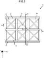
- FIG. 2 is a plan view of the xy plane, as viewed in the z-direction.
- FIG. 3A is a cross-sectional view taken along line IIIa-IIIa illustrated in FIG. 2 .
- FIG. 3B is a cross-sectional view taken along line IIIb-IIIb illustrated in FIG. 2 .
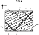
- FIG. 4 is a cross-sectional view taken along line IV-IV illustrated in FIG. 3 .
- FIG. 5 is a conceptual diagram illustrating the unit structure 10X, which is an example of the plurality of embodiments.
- the first conductive layer 41 includes a patch resonator that serves as the first unit resonator 41X.
- the second conductive layer 42 includes a patch resonator that serves as the second unit resonator 42X.
- the unit resonator 40X includes one first unit resonator 41X and four second divisional resonators 42Y.
- the unit structure 10X includes the unit resonator 40X, part of the base 20 that overlaps the unit resonator 40X in the z-direction, and part of the fourth conductor 50.
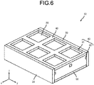
- FIGS. 6 to 9 are diagrams illustrating a resonator 10, which is an example of the plurality of embodiments.
- FIG. 6 is a schematic diagram of the resonator 10.
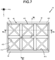
- FIG. 7 is a plan view of the xy plane, as viewed in the z-direction.
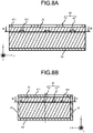
- FIG. 8A is a cross-sectional view taken along line VIIIa-VIIIa illustrated in FIG. 7 .
- FIG. 8B is a cross-sectional view taken along line VIIIb-VIIIb illustrated in FIG. 7 .
- FIG. 9 is a cross-sectional view taken along line IX-IX illustrated in FIG. 8 .
- the first conductive layer 41 includes a slot resonator that serves as the first unit resonator 41X.
- the second conductive layer 42 includes a slot resonator that serves as the second unit resonator 42X.
- the unit resonator 40X includes one first unit resonator 41X and four second divisional resonators 42Y.
- the unit structure 10X includes the unit resonator 40X, part of the base 20 that overlaps the unit resonator 40X in the z-direction, and part of the fourth conductor 50.
- FIGS. 10 to 13 are diagrams illustrating a resonator 10, which is an example of the plurality of embodiments.
- FIG. 10 is a schematic diagram of the resonator 10.
- FIG. 11 is a plan view of the xy plane, as viewed in the z-direction.
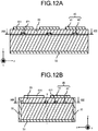
- FIG. 12A is a cross-sectional view taken along line XIIa-XIIa illustrated in FIG. 11 .
- FIG. 12B is a cross-sectional view taken along line XIIb-XIIb illustrated in FIG. 11 .
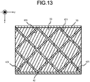
- FIG. 13 is a cross-sectional view taken along line XIII-XIII illustrated in FIG. 12 .
- the first conductive layer 41 includes a patch resonator that serves as the first unit resonator 41X.
- the second conductive layer 42 includes a slot resonator that serves as the second unit resonator 42X.
- the unit resonator 40X includes one first unit resonator 41X and four second divisional resonators 42Y.
- the unit structure 10X includes the unit resonator 40X, part of the base 20 that overlaps the unit resonator 40X in the z-direction, and part of the fourth conductor 50.
- FIGS. 14 to 17 are diagrams illustrating a resonator 10, which is an example of the plurality of embodiments.
- FIG. 14 is a schematic diagram of the resonator 10.
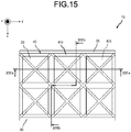
- FIG. 15 is a plan view of the xy plane, as viewed in the z-direction.
- FIG. 16A is a cross-sectional view taken along line XVIa-XVIa illustrated in FIG. 15 .
- FIG. 16B is a cross-sectional view taken along line XVIb-XVIb illustrated in FIG. 15 .
- FIG. 17 is a cross-sectional view taken along line XVII-XVII illustrated in FIG. 16 .
- the first conductive layer 41 includes a slot resonator that serves as the first unit resonator 41X.
- the second conductive layer 42 includes a patch resonator that serves as the second unit resonator 42X.
- the unit resonator 40X includes one first unit resonator 41X and four second divisional resonators 42Y.
- the unit structure 10X includes the unit resonator 40X, part of the base 20 that overlaps the unit resonator 40X in the z-direction, and part of the fourth conductor 50.
- FIGS. 1 to 17 are diagrams each illustrating the resonator 10 as an example.
- the configuration of the resonator 10 is not limited to the structures illustrated in FIGS. 1 to 17 .
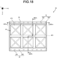
- FIG. 18 is a diagram illustrating the resonator 10 including the pair conductors 30 having another configuration.
- FIG. 19A is a cross-sectional view taken along line XIXa-XIXa illustrated in FIG. 18 .
- FIG. 19B is a cross-sectional view taken along line XIXb-XIXb illustrated in FIG. 18 .
- FIGS. 1 to 19 are diagrams each illustrating the base 20 as an example.
- the configuration of the base 20 is not limited to the configurations illustrated in FIGS. 1 to 19 .
- the base 20 can internally include a cavity 20a, as illustrated in FIG. 20 .
- the cavity 20a is located between the third conductor 40 and the fourth conductor 50 in the z-direction.
- a dielectric constant of the cavity 20a is lower than a dielectric constant of the base 20.
- the base 20 including the cavity 20a can reduce an electromagnetic distance between the third conductor 40 and the fourth conductor 50.
- the base 20 can include a plurality of members, as illustrated in FIG. 21 .
- the base 20 can include a first base 21, a second base 22, and a connector 23.
- the first base 21 and the second base 22 can be mechanically connected via the connector 23.
- the connector 23 can internally include a sixth conductor 303.
- the sixth conductor 303 is electrically connected to a fourth conductor 301 or a fifth conductor 302.
- the sixth conductor 303 is formed as the first conductor 31 or the second conductor 32 together with the fourth conductor 301 and the fifth conductor 302.
- FIGS. 1 to 21 are diagrams each illustrating the pair conductors 30 as an example.
- the configuration of the pair conductors 30 is not limited to the configurations illustrated in FIGS. 1 to 21 .
- FIGS. 22 to 28 are diagrams illustrating resonators 10 which includes other pair conductors 30 having other configurations.
- FIG. 22 is a cross-sectional view corresponding to FIG. 19A .
- the number of the fifth conductive layers 301 can be changed as appropriate.
- the fifth conductive layer 301 may not be located on the base 20.
- the fifth conductive layer 301 may not be located within the base 20.
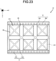
- FIG. 23 is a plan view corresponding to FIG. 18 .
- the fifth conductor 302 can be separated from the boundary of the unit resonator 40X.
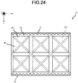
- FIG. 24 is a plan view corresponding to FIG. 18 .
- two pair conductors 30 each can include protrusions that protrude toward the other of the pair conductors 30.
- Such a resonator 10 can be formed, for example, by applying metal paste to the base 20 having recesses and curing the metal paste.
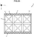
- FIG. 25 is a plan view corresponding to FIG. 18 .
- the base 20 can have recesses.
- the pair conductors 30 each have recesses that are recessed inward in the x-direction from an outer surface.
- the pair conductors 30 each extend along a surface of the base 20.
- Such a resonator 10 can be formed, for example, by spraying a fine metal material onto the base 20 having recesses.
- FIG. 26 is a plan view corresponding to FIG. 18 .
- the base 20 can have recesses.
- the pair conductors 30 each have recesses that are recessed inward in the x-direction from an outer surface.
- the pair conductors 30 each extend along the recesses of the base 20.
- Such a resonator 10 can be manufactured, for example, by dividing a mother substrate along an array of through-hole conductors.
- Such pair conductors 30 can be referred to as an end surface through-hole or the like.
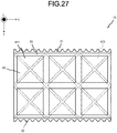
- FIG. 27 is a plan view corresponding to FIG. 18 .
- the base 20 can have recesses.
- the pair conductors 30 each have recesses that are recessed inward in the x-direction from an outer surface.
- Such a resonator 10 can be manufactured, for example, by dividing a mother substrate along an array of through-hole conductors.
- Such pair conductors 30 can be referred to as an end surface through-hole or the like.
- FIG. 28 is a plan view corresponding to FIG. 18 .
- pair conductors 30 each may have a smaller length in the x-direction than the base 20.
- the configuration of the pair conductors 30 is not limited to these configurations.
- Two pair conductors 30 can have different configurations.
- one of the pair conductors 30 may include the fifth conductive layer 301 and the fifth conductor 302, and the other of the pair conductors 30 may include an end surface through-hole.
- FIGS. 1 to 28 are diagrams each illustrating the third conductor 40 as an example.
- the configuration of the third conductor 40 is not limited to the configurations illustrated in FIGS. 1 to 28 .
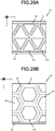
- the unit resonator 40X, the first unit resonator 41X, and the second unit resonator 42X are not limited to the square shape.
- the unit resonator 40X, the first unit resonator 41X, and the second unit resonator 42X can be referred to as the unit resonator 40X and the like.
- the unit resonators 40X and the like may have a triangular shape as illustrated in FIG. 29A and may have a hexagonal shape as illustrated in FIG. 29B . As illustrated in FIG.
- each side of the unit resonator 40X and the like can extend in a direction different from the x-direction and the y-direction.
- the second conductive layer 42 can be located on the base 20 and the first conductive layer 41 can be located within the base 20.
- the second conductive layer 42 can be located farther from the fourth conductor 50 than the first conductive layer 41.
- FIGS. 1 to 30 are diagrams each illustrating the third conductor 40 as an example.
- the configuration of the third conductor 40 is not limited to the configurations illustrated in FIGS. 1 to 30 .
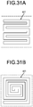
- the resonator including the third conductor 40 may be a linear resonator 401.
- FIG. 31A illustrates a meander-line resonator 401.
- FIG. 31B illustrates a spiral resonator 401.
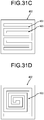
- the resonator including the third conductor 40 may be a slot resonator 402.
- the slot resonator 402 can have one or a plurality of seventh conductors 403 in an opening.
- the seventh conductors 403 in the opening has one end that is opened and the other end that is electrically connected to a conductor defining the opening.
- a unit slot illustrated in FIG. 31C five seventh conductors 403 are located in an opening. In the unit slot, the seventh conductors 403 form a shape corresponding to a meander line. In a unit slot illustrated in FIG. 31D , one seventh conductor 403 is located in an opening. In the unit slot, the seventh conductor 403 forms a shape corresponding to a spiral.
- FIGS. 1 to 31 are diagrams each illustrating a configuration of the resonator 10 as an example.
- the configuration of the resonator 10 is not limited to the configurations illustrated in FIGS. 1 to 31 .
- the resonator 10 can include three or more pair conductors 30.
- one of the pair conductors 30 can face two pair conductors 30 in the x-direction.
- the two pair conductors 30 have different distances from the one of the pair conductors 30.
- the resonator 10 can include two pairs of pair conductors 30. In the two pairs of pair conductors 30, the distances between the respective pairs and the lengths of the respective pairs are different.
- the resonator 10 can include five or more first conductors.
- the resonator 10 includes the unit structure 10X that can be aligned with another unit structure 10X in the y-direction.
- the unit structure 10X of the resonator 10 can be aligned with another unit structure 10X in the x-direction without through the pair conductors 30.
- FIGS. 32 to 34 are diagrams illustrating examples of the resonators 10. In the resonators 10 illustrated in FIGS. 32 to 34 , the unit resonator 40X of the unit structure 10X is represented as a square, but the unit resonator 40X is not limited to this shape.
- FIGS. 1 to 34 are diagrams each illustrating a configuration of the resonator 10 as an example.
- the configuration of the resonator 10 are not limited to the configurations illustrated in FIGS. 1 to 34 .
- FIG. 35 is a plan view of the xy plane, as viewed in the z-direction.
- FIG. 36A is a cross-sectional view taken along line XXXVIa-XXXVIa illustrated in FIG. 35
- FIG. 36B is a cross-sectional view taken along line XXXVIb-XXXVIb illustrated in FIG. 35 .
- the first conductive layer 41 includes half of a patch resonator as the first unit resonator 41X.
- the second conductive layer 42 includes half of a patch resonator as the second unit resonator 42X.
- the unit resonator 40X includes one first divisional resonator 41Y and one second divisional resonator 42Y.
- the unit structure 10X includes the unit resonator 40X, part of the base 20 overlapping the unit resonator 40X in the z-direction, and part of the fourth conductor 50.
- three unit resonators 40X are arranged in the x-direction.
- the first unit conductor 411 and the second unit conductor 421 included in the three unit resonators 40X form one current path 401.
- FIG. 37 illustrates another example of the resonator 10 illustrated in FIG. 35 .
- the resonator 10 illustrated in FIG. 37 has a length larger in the x-direction than the resonator 10 illustrated in FIG. 35 .
- the size of the resonator 10 is not limited to the resonator 10 illustrated in FIG. 37 and can be changed as appropriate.
- the first connecting conductor 413 has a length in the x-direction that is different from the first floating conductor 414.
- the length of the first connecting conductor 413 in the x-direction is smaller than that of the first floating conductor 414.
- the third conductor 40 has different lengths in the x-direction.
- the length of the first connecting conductor 413 in the x-direction is larger than that of the first floating conductor 414.
- FIG. 39 illustrates another example of the resonator 10.
- FIG. 39 illustrates another example of the resonator 10 illustrated in FIG. 37 .
- a plurality of first unit conductors 411 and second unit conductors 421 arranged in the x-direction are capacitively coupled.
- two current paths 401 can be arranged in y-directions in which no current flows from one side to the other side.
- FIG. 40 illustrates another example of the resonator 10.
- FIG. 40 illustrates another example of the resonator 10 illustrated in FIG. 39 .
- the resonator 10 can be configured such that the number of conductive members connected to the first conductor 31 and the number of conductive members connected to the second conductor 32 are different in number.
- one first connecting conductor 413 is capacitively coupled to two second floating conductors 424.
- the two second connecting conductors 423 are capacitively coupled to one first floating conductor 414.
- the number of first unit conductors 411 can be different from the number of second unit conductors 421 capacitively coupled to the first unit conductors 411.
- FIG. 41 illustrates another example of the resonator 10 illustrated in FIG. 39 .
- the first unit conductor 411 can be configured such that the number of second unit conductors 421 capacitively coupled at a first end in the x-direction and the number of second unit conductors 421 capacitively coupled at a second end in the x-direction are different.
- one second floating conductor 424 has a first end in the x-direction to which two first connecting conductors 413 are capacitively coupled and a second end to which three second floating conductors 424 are capacitively coupled.
- a plurality of conductive members arranged in the y-direction can have different lengths in the y-direction.
- the three first floating conductors 414 arranged in the y-direction have different lengths in the y-direction.
- FIG. 42 illustrates another example of the resonator 10.
- FIG. 43 is a cross-sectional view taken along line XLIII-XLIII illustrated in FIG. 42 .
- the first conductive layer 41 includes half of a patch resonator as the first unit resonator 41X.
- the second conductive layer 42 includes half of a patch resonator as the second unit resonator 42X.
- the unit resonator 40X includes one first divisional resonator 41Y and one second divisional resonator 42Y.
- the unit structure 10X includes the unit resonator 40X, part of the base 20 that overlaps the unit resonator 40X in the z-direction, and part of the fourth conductor 50.
- one unit resonator 40X extends in the x-direction.
- FIG. 44 illustrates another example of the resonator 10.
- FIG. 45 is a cross-sectional view taken along line XLV-XLV illustrated in FIG. 44
- the third conductor 40 includes only the first connecting conductor 413.
- the first connecting conductor 413 faces the first conductor 31 in the xy plane.
- the first connecting conductor 413 is capacitively coupled to the first conductor 31.
- FIG. 46 illustrates another example of the resonator 10.
- FIG. 47 is a cross-sectional view taken along line XLVII-XLVII illustrated in FIG. 46 .
- the third conductor 40 includes the first conductive layer 41 and the second conductive layer 42.
- the first conductive layer 41 includes one first floating conductor 414.
- the second conductive layer 42 includes two second connecting conductors 423.
- the first conductive layer 41 faces the pair conductors 30 in the xy plane.
- the two second connecting conductors 423 overlap the one first floating conductor 414 in the z-direction.
- the one first floating conductor 414 is capacitively coupled to the two second connecting conductors 423.
- FIG. 48 illustrates another example of the resonator 10.
- FIG. 49 is a cross-sectional view taken along line XLIX-XLIX illustrated in FIG. 48 .
- the third conductor 40 includes only the first floating conductor 414.
- the first floating conductor 414 faces the pair conductors 30 in the xy plane.
- the first connecting conductor 413 is capacitively coupled to the pair conductors 30.
- FIG. 50 illustrates another example of the resonator 10.
- FIG. 51 is a cross-sectional view taken along line LI-LI illustrated in FIG. 50 .
- the resonator 10 illustrated in FIGS. 50 and 51 is different from the resonator 10 illustrated in FIGS. 42 and 43 in the configuration of the fourth conductor 50.
- the resonator 10 illustrated in FIGS. 50 and 51 includes the fourth conductor 50 and the reference potential layer 51.
- the reference potential layer 51 is electrically connected to the ground of a device including the resonator 10.
- the reference potential layer 51 faces the third conductor 40 via the fourth conductor 50.
- the fourth conductor 50 is located between the third conductor 40 and the reference potential layer 51.
- the distance between the reference potential layer 51 and the fourth conductor 50 is smaller than the distance between the third conductor 40 and the fourth conductor 50.
- FIG. 52 illustrates another example of the resonator 10.
- FIG. 53 is a cross-sectional view taken along line LIII-LIII illustrated in FIG. 52 .
- the resonator 10 includes the fourth conductor 50 and the reference potential layer 51.
- the reference potential layer 51 is electrically connected to the ground of a device including the resonator 10.
- the fourth conductor 50 includes a resonator.
- the fourth conductor 50 includes the third conductive layer 52 and the fourth conductive layer 53.
- the third conductive layer 52 and the fourth conductive layer 53 are capacitively coupled.
- the third conductive layer 52 and the fourth conductive layer 53 face each other in the z-direction.
- the distance between the third conductive layer 52 and the fourth conductive layer 53 is smaller than the distance between the fourth conductive layer 53 and the reference potential layer 51.
- the distance between the third conductive layer 52 and the fourth conductive layer 53 is shorter than the distance between the fourth conductor 50 and the reference potential layer 51.
- the third conductor 40 is formed into one conductive layer.
- FIG. 54 illustrates another example of the resonator 10 illustrated in FIG. 53 .
- the resonator 10 includes the third conductor 40, the fourth conductor 50, and the reference potential layer 51.
- the third conductor 40 includes the first conductive layer 41 and the second conductive layer 42.
- the first conductive layer 41 includes the first connecting conductor 413.
- the second conductive layer 42 includes the second connecting conductor 423.
- the first connecting conductor 413 is capacitively coupled to the second connecting conductor 423.
- the reference potential layer 51 is electrically connected to the ground of a device including the resonator 10.
- the fourth conductor 50 includes the third conductive layer 52 and the fourth conductive layer 53.
- the third conductive layer 52 and the fourth conductive layer 53 are capacitively coupled.
- the third conductive layer 52 and the fourth conductive layer 53 face each other in the z-direction.
- the distance between the third conductive layer 52 and the fourth conductive layer 53 is smaller than the distance between the fourth conductive layer 53 and the reference potential layer 51.
- the distance between the third conductive layer 52 and the fourth conductive layer 53 is shorter than the distance between the fourth conductor 50 and the reference potential layer 51.
- FIG. 55 illustrates another example of the resonator 10.
- FIG. 56A is a cross-sectional view taken along line LVIa-LVIa illustrated in FIG. 55 .
- FIG. 56B is a cross-sectional view taken along line LVIb-LVIb illustrated in FIG. 55 .
- the first conductive layer 41 includes four first floating conductors 414.
- the first conductive layer 41 illustrated in FIG. 55 does not include the first connecting conductor 413.
- the second conductive layer 42 includes six second connecting conductors 423 and three second floating conductors 424. Two of the second connecting conductors 423 are each capacitively coupled to two of the first floating conductors 414.
- One of the second floating conductors 424 is capacitively coupled to four first floating conductors 414.
- Two of the second floating conductors 424 are capacitively coupled to two first floating conductors 414.
- FIG. 57 is a diagram illustrating another example of the resonator illustrated in FIG. 55 .
- the resonator 10 of FIG. 57 is different from the resonator 10 illustrated in FIG. 55 in the size of the second conductive layer 42.
- the length of each second floating conductor 424 in the x-direction is smaller than the length of each second connecting conductor 423 in the x-direction.
- FIG. 58 is a diagram illustrating another example of the resonator illustrated in FIG. 55 .
- the resonator 10 of FIG. 58 is different from the resonator 10 illustrated in FIG. 55 in the size of the second conductive layer 42.
- the plurality of second unit conductors 421 has different first areas.
- the plurality of second unit conductors 421 has different lengths in x-directions.
- the plurality of second unit conductors 421 has different lengths in y-directions.
- FIG. 58 the plurality of second unit conductors 421 has different lengths in y-directions.
- the plurality of second unit conductors 421 has, but is not limited to, different first areas, lengths, and widths.
- the plurality of second unit conductors 421 can be different from each other in part of first area, length, and width.
- the plurality of second unit conductors 421 can match each other in part or all of first area, length, and width.
- the plurality of second unit conductors 421 can be different from each other in part or all of first area, length, and width.
- the plurality of second unit conductors 421 can match each other in part or all of first area, length, and width. Part of the plurality of second unit conductors 421 can match each other in part or all of first area, length, and width.
- the plurality of second connecting conductors 423 arranged in the y-direction has different first areas.
- the plurality of second connecting conductors 423 arranged in the y-direction has different lengths in x-directions.
- the plurality of second connecting conductors 423 arranged in the y-direction has different lengths in the y-direction.
- the plurality of second connecting conductors 423 has, but is not limited to, different first areas, lengths, and widths.
- the plurality of second connecting conductors 423 can be different from each other in part of first area, length, and width.
- the plurality of second connecting conductors 423 can match each other in part or all of first area, length, and width.
- the plurality of second connecting conductors 423 can be different from each other in part or all of first area, length, and width.
- the plurality of second connecting conductors 423 can match each other in part or all of first area, length, and width.
- Part of the plurality of second connecting conductors 423 can match each other in part or all of first area, length, and width.
- a plurality of second floating conductors 424 arranged in the y-direction has different first areas.
- the plurality of second floating conductors 424 arranged in the y-direction has different lengths in x-directions.
- the plurality of second floating conductors 424 arranged in the y-direction has different lengths in the y-direction.
- the plurality of second floating conductors 424 has, but is not limited to, different first areas, lengths, and widths.
- the plurality of second floating conductors 424 can be different from each other in part of first area, length, and width.
- the plurality of second floating conductors 424 can match each other in part or all of first area, length, and width.
- the plurality of second floating conductors 424 can be different from each other in part or all of first area, length, and width.
- the plurality of second floating conductors 424 can match each other in part or all of first area, length, and width.
- Part of the plurality of second floating conductors 424 can match each other in part or all of first area, length, and width.
- FIG. 59 is a diagram illustrating another example of the resonator 10 illustrated in FIG. 57 .
- the resonator 10 of FIG. 59 is different from the resonator 10 illustrated in FIG. 57 in distance between first unit conductors 411 in the y-direction.
- a distance between first unit conductors 411 in the y-direction is smaller than a distance between first unit conductors 411 in the x-direction.
- the pair conductors 30 can function as the electric walls, current flows in the x-direction.
- current flowing through the third conductor 40 in the y-direction can be ignored.
- the distance between the first unit conductors 411 in the y-direction can be reduced relative to the distance between the first unit conductors 411 in the x-direction.
- the distance between the first unit conductors 411 in the y-direction can be reduced to increase the areas of the first unit conductors 411.
- FIGS. 60 to 62 are diagrams illustrating other examples of the resonators 10. These resonators 10 have the impedance element 45.
- a unit conductor to which the impedance element 45 is connected is not limited to the examples illustrated in FIGS. 60 to 62 . Part of the impedance elements 45 illustrated in FIGS. 60 to 62 can be omitted.
- the impedance element 45 can have capacitance characteristics.
- the impedance element 45 can have inductance characteristics.
- the impedance element 45 can be a mechanical or electrical variable element.
- the impedance element 45 can connect two different conductors located in one layer.
- An antenna has at least one of a function of radiating electromagnetic waves and a function of receiving electromagnetic waves.
- An antenna according to the present disclosure includes, but is not limited to, a first antenna 60 and a second antenna 70.
- the first antenna 60 includes the base 20, the pair conductors 30, the third conductor 40, the fourth conductor 50, and a first feeding line 61.
- the first antenna 60 includes a third base 24 on the base 20.
- the third base 24 can have a different composition from the composition of the base 20.
- the third base 24 can be located above the third conductor 40.
- FIGS. 63 to 76 are diagrams each illustrating the first antenna 60 as an example of the plurality of embodiments.
- the first feeding line 61 supplies power to at least one of resonators arranged periodically as artificial magnetic walls.
- the first antenna 60 can include a plurality of first feeding lines.
- the first feeding line 61 can be electromagnetically connected to any of the resonators arranged periodically as the artificial magnetic walls.
- the first feeding line 61 can be electromagnetically connected to any of a pair of conductors that appear as electric walls from the resonators arranged periodically as the artificial magnetic walls.
- the first feeding line 61 supplies power to at least one of the first conductor 31, the second conductor 32, and the third conductor 40.
- the first antenna 60 can include a plurality of first feeding lines.
- the first feeding line 61 can be electromagnetically connected to any of the first conductor 31, second conductor 32, and third conductor 40.
- the first antenna 60 includes the reference potential layer 51 in addition to the fourth conductor 50
- the first feeding line 61 can be electromagnetically connected to any of the first conductor 31, second conductor 32, third conductor 40, and fourth conductor 50.
- the first feeding line 61 is electrically connected to any of the fifth conductive layer 301 or the fifth conductor 302 of the pair conductors 30.
- the first feeding line 61 can be partially integrated with the fifth conductive layer 301.
- the first feeding line 61 can be electromagnetically connected to the third conductor 40.
- the first feeding line 61 is electromagnetically connected to one of first unit resonators 41X.
- the first feeding line 61 is electromagnetically connected to one of second unit conductors 42X.
- the first feeding line 61 is electromagnetically connected to a unit conductor of the third conductor 40 at a point different from the center in the x-direction.
- the first feeding line 61 supplies power to at least one resonator included in the third conductor 40.
- the first feeding line 61 supplies power from at least one resonator included in the third conductor 40 to the outside. At least part of the first feeding line 61 can be located within the base 20.
- the first feeding line 61 can be exposed to the outside from any of two zx surfaces, two yz surfaces, and two xy surfaces of the base 20.
- the first feeding line 61 can make contact with the third conductor 40 in a forward direction and reverse direction of the z-direction.
- the fourth conductor 50 can be omitted around the first feeding line 61.
- the first feeding line 61 can be electromagnetically connected to the third conductor 40 through the opening of the fourth conductor 50.
- the first conductive layer 41 can be omitted around the first feeding line 61.
- the first feeding line 61 can be connected to the second conductive layer 42 through the opening of the first conductive layer 41.
- the first feeding line 61 can make contact with the third conductor 40 along the xy plane.
- the pair conductors 30 can be omitted around the first feeding line 61.
- the first feeding line 61 can be connected to the third conductor 40 through the openings of the pair conductors 30.
- the first feeding line 61 is connected to a unit conductor of the third conductor 40, apart from the center of the unit conductor.
- FIG. 63 is a plan view of the first antenna 60 in the xy plane, as viewed in the z-direction.
- FIG. 64 is a cross-sectional view taken along line LXIV-LXIV illustrated in FIG. 63 .
- the first antenna 60 illustrated in FIGS. 63 and 64 includes the third base 24 above the third conductor 40.
- the third base 24 has an opening above the first conductive layer 41.
- the first feeding line 61 is electrically connected to the first conductive layer 41 via the opening of the third base 24.
- FIG. 65 is a plan view of the first antenna 60 in the xy plane, as viewed in the z-direction.
- FIG. 66 is a cross-sectional view taken along line LXVI-LXVI illustrated in FIG. 65 .
- the first feeding line 61 is partially located on the base 20.
- the first feeding line 61 can be connected to the third conductor 40 in the xy plane.
- the first feeding line 61 can be connected to the first conductive layer 41 in the xy plane.
- the first feeding line 61 can be connected to the second conductive layer 42 in the xy plane.
- FIG. 67 is a plan view of the first antenna 60 in the xy plane, as viewed in the z-direction.
- FIG. 68 is a cross-sectional view taken along line LXVIII-LXVIII illustrated in FIG. 67 .
- the first feeding line 61 is located within the base 20.
- the first feeding line 61 can be connected to the third conductor 40 in a reverse direction of the z-direction.
- the fourth conductor 50 can have an opening.
- the fourth conductor 50 can have an opening at a position where the fourth conductor 50 overlaps the third conductor 40 in the z-direction.
- the first feeding line 61 can be exposed to the outside of the base 20 through the opening.
- FIG. 69 is a cross-sectional view of the first antenna 60 as viewed in the yz plane in the x-direction.
- the pair conductors 30 can have an opening.
- the first feeding line 61 can be exposed to the outside of the base 20 through the opening.
- An electromagnetic wave radiated by the first antenna 70 has a polarization component in the x-direction that is larger than that in the y-direction, in the first plane.
- the polarization component in the x-direction has less attenuation than a horizontal polarization component when a metal plate approaches the fourth conductor 50 in the z-direction.
- the first antenna 70 can maintain radiation efficiency when a metal plate approaches from outside.
- FIG. 70 illustrates another example of the first antenna 60.
- FIG. 71 is a cross-sectional view taken along line LXXI-LXXI illustrated in FIG. 70 .
- FIG. 72 illustrates another example of the first antenna 60.
- FIG. 73 is a cross-sectional view taken along line LXXIII-LXXIII illustrated in FIG. 72 .
- FIG. 74 illustrates another example of the first antenna 60.
- FIG. 75A is a cross-sectional view taken along line LXXVa-LXXVa illustrated in FIG. 74 .
- FIG. 75B is a cross-sectional view taken along line LXXVb-LXXVb illustrated in FIG. 74 .
- FIG. 76 illustrates another example of the first antenna 60.
- the first antenna 60 illustrated in FIG. 76 has an impedance element 45.
- the operating frequency of the first antenna 60 can be changed by the impedance element 45.
- the first antenna 60 includes a first feeding conductor 415 that is connected to the first feeding line 61 and the first unit conductor 411 that is not connected to the first feeding line 61. Impedance matching changes when the impedance element 45 is connected to the first feeding conductor 415 and another conductive member.
- the impedance matching can be adjusted by connecting the first feeding conductor 415 and another conductive member by the impedance element 45.
- the impedance element 45 can be inserted between the first feeding conductor 415 and the other conductive member to adjust the impedance matching.
- the impedance element 45 can be inserted between two first unit conductors 411 that are not connected to the first feeding line 61 to adjust the operating frequency. In the first antenna 60, the impedance element 45 can be inserted between the first unit conductor 411 that is not connected to the first feeding line 61 and any of the pair conductors 30 to adjust the operating frequency.
- the second antenna 70 includes the base 20, the pair conductors 30, the third conductor 40, the fourth conductor 50, a second feeding layer 71, and a second feeding line 72.
- the third conductor 40 is located within the base 20.
- the second antenna 70 includes the third base 24 above the base 20.
- the third base 24 can have a different composition from the composition of the base 20.
- the third base 24 can be located above the third conductor 40.
- the third base 24 can be located above the second feeding layer 71.
- the second feeding layer 71 is spaced above the third conductor 40.
- the base 20 or the third base 24 can be located between the second feeding layer 71 and the third conductor 40.
- the second feeding layer 71 includes a line resonator, patch resonator, and slot resonator.
- the second feeding layer 71 can be referred to as an antenna element.
- the second feeding layer 71 can be electromagnetically coupled to the third conductor 40.
- the second feeding layer 71 has a resonant frequency that changes from a single resonant frequency due to the electromagnetic coupling to the third conductor 40.
- the second feeding layer 71 receives power transmitted from the second feeding line 72 and resonates with the third conductor 40.
- the second feeding layer 71 receives power transmitted from the second feeding line 72 and resonates with the third conductor 40 and the third conductor.
- the second feeding line 72 is electrically connected to the second feeding layer 71. In an embodiment, the second feeding line 72 transmits power to the second feeding layer 71. In an embodiment, the second feeding line 72 transmits power from the second feeding layer 71 to the outside.
- FIG. 77 is a plan view of the second antenna 70 in the xy plane, as viewed in the z-direction.
- FIG. 78 is a cross-sectional view taken along line LXXVIII-LXXVIII illustrated in FIG. 77 .
- the third conductor 40 is located within the base 20.
- the second feeding layer 71 is located above the base 20.
- the second feeding layer 71 is located so as to overlap a unit structure 10X in the z-direction.
- the second feeding line 72 is located on the base 20.
- the second feeding line 72 is electromagnetically connected to the second feeding layer 71 in the xy plane.
- a wireless communication module includes a wireless communication module 80 as an example of the plurality of embodiments.
- FIG. 79 is a block structural diagram of the wireless communication module 80.
- FIG. 80 is a schematic configuration diagram of the wireless communication module 80.
- the wireless communication module 80 includes the first antenna 60, a circuit board 81, and an RF module 82.
- the wireless communication module 80 can include the second antenna 70 instead of the first antenna 60.
- the first antenna 60 is located on the circuit board 81.
- the first antenna 60 includes the first feeding line 61 that is electromagnetically connected to the RF module 82 via the circuit board 81.
- the first antenna 60 includes the fourth conductor 50 that is electromagnetically connected to a ground conductor 811 of the circuit board 81.
- the ground conductor 811 can extend in the xy plane.
- the ground conductor 811 has a larger area than the fourth conductor 50, in the xy plane.
- the ground conductor 811 has a larger length than the fourth conductor 50, in the y-direction.
- the ground conductor 811 has a larger length than the fourth conductor 50, in the x-direction.
- the first antenna 60 can be located closer to an end side relative to the center of the ground conductor 811, in the y-direction.
- the center of the first antenna 60 may not coincide with the center of the ground conductor 811 in the xy plane.
- the center of the first antenna 60 may not coincide with the centers of a first conductor 41 and second conductor 42.
- a point at which the first feeding line 61 is connected to the third conductor 40 may not coincide with the center of the ground conductor 811 in the xy plane.
- first current and second current flow in a loop via the pair conductors 30.
- the first antenna 60 is located on the end side in the y-direction relative to the center of the ground conductor 811, and thus, the second current flowing through the ground conductor 811 becomes outside a target.
- the polarization component of a radiation wave in the x-direction is increased, in an antenna structure including the first antenna 60 and the ground conductor 811. The increased polarization component of the radiation wave in the x-direction can improve the total radiation efficiency of the radiation wave.
- the RF module 82 can control power supplied to the first antenna 60.
- the RF module 82 modulates a baseband signal and supplies the baseband signal to the first antenna 60.
- the RF module 82 can modulate an electric signal received by the first antenna 60 into a baseband signal.
- a change in the resonant frequency of the first antenna 60 is small due to a conductor of the circuit board 81 side.
- the first antenna 60 of the wireless communication module 80 can reduce the influence from an external environment.
- the first antenna 60 can be integrated with the circuit board 81.
- the fourth conductor 50 and the ground conductor 811 are integrally configured.
- a wireless communication device includes a wireless communication device 90 as an example of the plurality of embodiments.
- FIG. 81 is a block structural diagram of the wireless communication device 90.
- FIG. 82 is a plan view of the wireless communication device 90. Part of the configuration of the wireless communication device 90 illustrated in FIG. 82 is omitted.
- FIG. 83 is a cross-sectional view of the wireless communication device 90. Part of the configuration of the wireless communication device 90 illustrated in FIG. 83 is omitted.
- the wireless communication device 90 includes the wireless communication module 80, a battery 91, a sensor 92, a memory 93, a controller 94, a first case 95, and a second case 96.
- the wireless module 80 of the wireless communication device 90 includes the first antenna 60 but can include the second antenna 70.
- FIG. 84 illustrates one of other embodiments of the wireless communication device 90.
- the first antenna 60 of the wireless communication device 90 can include the reference potential layer 51.
- the battery 91 supplies power to the wireless communication module 80.
- the battery 91 can supply power to at least one of the sensor 92, memory 93, and controller 94.
- the battery 91 can include at least one of a primary battery and a secondary battery.
- a negative electrode of the battery 91 is electrically connected to a ground terminal of a circuit board 81.
- the negative electrode of the battery 91 is electrically connected to a fourth conductor 50 of the antenna 60.
- the sensor 92 may include, for example, a speed sensor, vibration sensor, acceleration sensor, gyro-sensor, rotation angle sensor, angular velocity sensor, geomagnetic sensor, magnet sensor, temperature sensor, humidity sensor, atmospheric pressure sensor, optical sensor, illuminance sensor, UV sensor, gas sensor, gas concentration sensor, atmosphere sensor, level sensor, odor sensor, pressure sensor, air pressure sensor, contact sensor, wind sensor, infrared sensor, human sensor, displacement sensor, image sensor, weight sensor, smoke sensor, leak sensor, vital sensor, battery remaining amount sensor, ultrasonic sensor, a global positioning system (GPS) signal receiving device, or the like.
- GPS global positioning system
- the memory 93 can include, for example, a semiconductor memory or the like.
- the memory 93 can function as a work memory for the controller 94.
- the memory 93 can be included in the controller 94.
- the memory 93 stores a program in which processing contents for achieving each function of the wireless communication device 90 is described, information used for processing in the wireless communication device 90, and the like.
- the controller 94 can include, for example, a processor.
- the controller 94 may include one or more processors.
- the processor may include a general-purpose processor that is used for loading a specific program to execute a specific function and a dedicated processor that is dedicated to specific processing.
- the dedicated processor may include an application specific IC.
- the application specific IC is also referred to as ASIC.
- the processor may include a programmable logic device.
- the programmable logic device is also referred to as PLD.
- the PLD may include a field-programmable gate array (FPGA).
- the controller 94 may include any of an SoC (System-on-a-Chip) and an SiP (System In a Package) that are configured such that one or more processors cooperating with each other.
- the controller 94 may store a variety of information, a program for operating each component module of the wireless communication device 90, or the like in the memory 93.
- the controller 94 generates a transmission signal to be transmitted from the wireless communication device 90.
- the controller 94 may obtain measurement data, for example, from the sensor 92.
- the controller 94 may generate a transmission signal according to the measurement data.
- the controller 94 can transmit a baseband signal to the RF module 82 of the wireless communication module 80.
- the first case 95 and the second case 96 protect other devices of the wireless communication device 90.
- the first case 95 can extend in the xy plane.
- the first case 95 supports other devices.
- the first case 95 can support the wireless communication module 80.
- the wireless communication module 80 is located on an upper surface 95A of the first case 95.
- the first case 95 can support the battery 91.
- the battery 91 is located on the upper surface 95A of the first case 95.
- the wireless communication module 80 and the battery 91 are arranged in the x-direction on the upper surface 95A of the first case 95.
- the first conductor 31 is located between the battery 91 and the third conductor 40.
- the battery 91 is located behind the pair conductors 30 when viewed from the third conductor 40.
- the second case 96 can cover other devices.
- the second case 96 includes an under surface 96A located in the z-direction from the first antenna 60.
- the under surface 96A extends along the xy plane.
- the under surface 96A is not limited to a flat shape but can include irregularities.
- the second case 96 can have an eighth conductor 961.
- the eighth conductor 961 is located at least within, on the outer side, or on the inner side of the second case 96.
- the eighth conductor 961 is located at least on an upper surface or lateral side surface of the second case 96.
- the eighth conductor 961 faces the first antenna 60.
- the eighth conductor 961 includes a first body 9611 that faces the first antenna 60 in the z-direction.
- the eighth conductor 961 can include, in addition to the first body 9611, at least one of a second body that faces the first antenna 60 in the x-direction and a third body that faces the first antenna in the y-direction.
- the eighth conductor 961 partially faces the battery 91.
- the eighth conductor 961 can include a first extra-body 9612 that extends outward from the first conductor 31 in the x-direction.
- the eighth conductor 961 can include a second extra-body 9613 that extends outward from the second conductor 32 in the x-direction.
- the first extra-body 9612 can be electrically connected to the first body 9611.
- the second extra-body 9613 can be electrically connected to the first body 9611.
- the first extra-body 9612 of the eighth conductor 961 faces the battery 91 in the z-direction.
- the eighth conductor 961 can be capacitively coupled to the battery 91.
- the eighth conductor 961 can have capacitance between the eighth conductor 961 and the battery 91.
- the eighth conductor 961 is separated from the third conductor 40 of the first antenna 60.
- the eighth conductor 961 is not electrically connected to each conductor of the first antenna 60.
- the eighth conductor 961 can be separated from the first antenna 60.
- the eighth conductor 961 can be electromagnetically coupled to any conductor of the first antenna 60.
- the first body 9611 of the eighth conductor 961 can be electromagnetically coupled to the first antenna 60.
- the first body 9611 can overlap the third conductor 40 in plan view in the z-direction. Since the first body 9611 overlaps the third conductor 40, propagation due to electromagnetic coupling can be increased.
- the eighth conductor 961 can have a mutual inductance, due to electromagnetic coupling with the third conductor 40.
- the eighth conductor 961 extends in the x-direction.
- the eighth conductor 961 extends along the xy plane.
- the length of the eighth conductor 961 is larger than the length of the first antenna 60 in the x-direction.
- the length of the eighth conductor 961 in the x-direction is larger than the length of the first antenna 60 in the x-direction.
- the length of the eighth conductor 961 can be larger than that of 1/2 of the operating wavelength ⁇ of the wireless communication device 90.
- the eighth conductor 961 can include a portion extending along the y-direction.
- the eighth conductor 961 can bend in the xy plane.
- the eighth conductor 961 can include a portion extending in the z-direction.
- the eighth conductor 961 can bend from the xy plane to the yz plane or the zx plane.
- the first antenna 60 and the eighth conductor 961 can be electromagnetically coupled to function as a third antenna 97.
- the third antenna 97 may have an operating frequency f c that is different from the resonant frequency of the first antenna 60 alone.
- the operating frequency f c of the third antenna 97 may be closer to the resonant frequency of the first antenna 60 than the resonant frequency of the eighth conductor 961 alone.
- the operating frequency f c of the third antenna 97 can be within the resonant frequency band of the first antenna 60.
- the operating frequency f c of the third antenna 97 can be outside the resonant frequency band of the eighth conductor 961 alone.
- FIG. 85 illustrates another embodiment of the third antenna 97.
- the eighth conductor 961 can be configured integrally with the first antenna 61. In FIG. 85 , part of the configuration of the wireless communication device 90 is omitted. In the example of FIG. 85 , the second case 96 may not include the eighth conductor 961.
- the eighth conductor 961 is capacitively coupled to the third conductor 40.
- the eighth conductor 961 is electromagnetically coupled to the fourth conductor 50.
- the third antenna 97 includes the first extra-body 9612 and the second extra-body 9613 of the eighth conductor in the air, and thus, a gain is improved as compared with the first antenna 60.
- the wireless communication device 90 can be located on various objects.
- the wireless communication device 90 can be located on an electrical conductive body 99.
- FIG. 86 is a plan view illustrating an embodiment of the wireless communication device 90.
- the electrical conductive body 99 is a conductor that transmits electricity.
- the material of the electrical conductive body 99 can include a metal, highly-doped semiconductor, conductive plastic, and liquid containing ions.
- the electrical conductive body 99 can include a non-conductive layer that does not transmit electricity on the surface.
- a portion that transmits electricity and the non-conductive layer can contain a common element.
- the electrical conductive body 99 including aluminum can include the non-conductive layer of aluminum oxide on the surface.
- the portion that transmits electricity and the non-conductive layer can include different elements.
- the shape of the electrical conductive body 99 is not limited to a flat plate shape but can include a three-dimensional shape such as a box shape.
- the three-dimensional shape of the electrical conductive body 99 includes a rectangular parallelepiped shape or a cylindrical shape.
- the three-dimensional shape can include a shape partially depressed, a shape partially penetrated, and a shape partially protruded.
- the electrical conductive body 99 can be formed into a torus shape.
- the electrical conductive body 99 includes an upper surface 99A on which the wireless communication device 90 can be placed.
- the upper surface 99A can extend over the entire surface of the electrical conductive body 99.
- the upper surface 99A can be part of the electrical conductive body 99.
- the upper surface 99A can have a larger area than the wireless communication device 90.
- the wireless communication device 90 can be placed on the upper surface 99A of the electrical conductive body 99.
- the upper surface 99A can have a smaller area than the wireless communication device 90.
- the wireless communication device 90 can be partially placed on the upper surface 99A of the electrical conductive body 99.
- the wireless communication device 90 can be placed on the upper surface 99A of the electrical conductive body 99 in various orientations.
- the wireless communication device 90 can have any orientation.
- the wireless communication device 90 can be appropriately secured on the upper surface 99A of the electrical conductive body 99 with a fastener.
- the fastener includes a fastener that uses a surface for securing, such as double-sided tape and adhesive.
- the fastener includes a fastener that uses a point for securing, such as a screw and a nail.
- the upper surface 99A of the electrical conductive body 99 can include a portion extending in a j-direction. In the portion extending in the j-direction, a length extending in the j-direction is larger than a length extending in the k-direction.
- the j-direction and the k-direction are orthogonal to each other.
- the j-direction is a direction in which the electrical conductive body 99 extends long.
- the k-direction is a direction in which the electrical conductive body 99 has a length smaller than that in the j-direction.
- the wireless communication device 90 can be placed on the upper surface 99A such that the x-direction is along the j-direction.
- the wireless communication device 90 can be placed on the upper surface 99A of the electrical conductive body 99 so as to be aligned in the x-direction in which the first conductor 31 and the second conductor 32 are arranged.
- the first antenna 60 can be electromagnetically coupled to the electrical conductive body 99.
- second current flows in the x-direction.
- the electrical conductive body 99 electromagnetically coupled to the first antenna 60, the second current induces current.
- the angle between the x-direction and the j-direction can be 45 degrees or less.
- the ground conductor 811 of the wireless communication device 90 is separated from the electrical conductive body 99.
- the ground conductor 811 is separated from the electrical conductive body 99.
- the wireless communication device 90 can be placed on the upper surface 99A such that the direction along a long side of the upper surface 99A is aligned in the x-direction in which the first conductor 31 and the second conductor 32 are arranged.
- the upper surface 99A can include a diamond-shaped surface and a circular surface in addition to a rectangular surface.
- the electrical conductive body 99 can include a diamond-shaped surface. This diamond-shaped surface can be the upper surface 99A on which the wireless communication device 90 is placed.
- the wireless communication device 90 can be placed on the upper surface 99A such that a direction along a long diagonal of the upper surface 99A is aligned in the x-direction in which the first conductor 31 and the second conductor 32 are arranged.
- the upper surface 99A is not limited to a flat shape.
- the upper surface 99A can include irregularities.
- the upper surface 99A can include a curved surface.
- the curved surface includes a ruled surface.
- the curved surface includes a cylinder.
- the electrical conductive body 99 extends in the xy plane.
- a length in the x-direction can be larger than a length in the y-direction.
- the length in the y-direction can be smaller than that one half of a wavelength ⁇ c at the operating frequency f c of the third antenna 97.
- the wireless communication device 90 can be located on the electrical conductive body 99.
- the electrical conductive body 99 is located apart from the fourth conductor 50 in the z-direction. In the electrical conductive body 99, the length in the x-direction is larger than that of the fourth conductor 50. In the electrical conductive body 99, an area in the xy plane is larger than that of the fourth conductor 50.
- the electrical conductive body 99 is located apart from the ground conductor 811 in the z-direction. In the electrical conductive body 99, the length in the x-direction is larger than that of the ground conductor 811. In the electrical conductive body 99, an area in the xy plane is larger than that of the ground conductor 811.
- the wireless communication device 90 can be placed on the electrical conductive body 99 in an orientation aligned with the x-direction in which the first conductor 31 and the second conductor 32 are arranged, in a direction in which the electrical conductive body 99 extends long.
- the wireless communication device 90 can be placed on the electrical conductive body 99, in an orientation in which a direction in which the current of the first antenna 60 flows is aligned with a direction in which the electrical conductive body 99 extends long, in the xy plane.
- the first antenna 60 has a small change in resonant frequency due to the conductor of the circuit board 80 side.
- the first antenna 60 of the wireless communication device 90 can reduce the influence from an external environment.
- the ground conductor 811 is capacitively coupled to the electrical conductive body 99.
- the wireless communication device 90 includes the portion of the electrical conductive body 99 extending outward from the third antenna 97, and thus, a gain is improved as compared with the first antenna 60.
- the wireless communication device 90 can have different resonance circuits for use in the air and for use on the electrical conductive body 99.
- FIG. 87 illustrates a schematic circuit of a resonance structure for use in the air.
- FIG. 88 illustrates a schematic circuit of a resonance structure for use on the electrical conductive body 99.
- L3 is the inductance of the resonator 10
- L8 is the inductance of the eighth conductor 961
- L9 is the inductance of the electrical conductive body 99
- M is the mutual inductance between L3 and L8.
- C3 is the capacitance of the third conductor 40
- C4 is the capacitance of the fourth conductor 50
- C8 is the capacitance of the eighth conductor 961
- C8B is the capacitance between the eighth conductor 961 and the battery 91
- C9 is the electrical conductive body 99, the ground conductor 811 and the capacitance.
- R3 is the radiation resistance of the resonator 10
- R8 is the radiation resistance of the eighth conductor 961.
- the operating frequency of the resonator 10 is lower than the resonant frequency of the eighth conductor.
- the ground conductor 811 functions as a chassis ground in the air.
- the fourth conductor 50 is capacitively coupled to the electrical conductive body 99.
- the electrical conductive body 99 substantially functions as the chassis ground.
- the wireless communication device 90 includes the eighth conductor 961.
- the eighth conductor 961 is electromagnetically coupled to the first antenna 60 and capacitively coupled to the fourth conductor 50.
- the wireless communication device 90 has capacitance C8B increased due to the capacitive coupling, and when the wireless communication device 90 is put on the electrical conductive body 99 from the air, the operating frequency thereof can be increased.
- the wireless communication device 90 has mutual inductance M increased due to the electromagnetic coupling, and when the wireless communication device 90 is put on the electrical conductive body 99 from the air, the operating frequency can be reduced.
- changing the balance between the capacitance C8B and the mutual inductance M can adjust the change in operating frequency when the wireless communication device 90 is placed on the electrical conductive body 99 from the air.
- changing the balance between the capacitance C8B and the mutual inductance M can reduce the change in operating frequency when the wireless communication device 90 is placed on the electrical conductive body 99 from the air.
- the wireless communication device 90 includes the eighth conductor 961 that is electromagnetically coupled to the third conductor 40 and capacitively coupled to the fourth conductor 50.
- the wireless communication device 90 including the eighth conductor 961 can adjust the change in operating frequency when the wireless communication device 90 is placed on the electrical conductive body 99 from the air.
- the wireless communication device 90 including such an eighth conductor 961 can reduce the change in operating frequency when the wireless communication device 90 is placed on the electrical conductive body 99 from the air.
- the ground conductor 811 functions as the chassis ground in the air.
- the electrical conductive body 99 functions as a substantial chassis ground, on the electrical conductive body 99.
- the resonant structure including the resonator 10 can oscillate even if the chassis ground changes. This configuration corresponds to that the resonator 10 including the reference potential layer 51 and the resonator 10 not including the reference potential layer 51 can oscillate.
- FIG. 89 is an exterior view illustrating an embodiment of a bicycle 1.
- FIG. 90 is a view illustrating frames of the bicycle 1 illustrated in FIG. 89 .
- FIG. 91 is a view illustrating a crank 1b-1 and a chain wheel 1j of the bicycle 1 illustrated in FIG. 89 .
- FIG. 92 is a view illustrating a dual control lever 1h of the bicycle 1 illustrated in FIG. 89 .
- the bicycle 1 travels with human power.
- the "bicycle” of the present disclosure is not limited to a bicycle that travels with only human power.
- the "bicycle” may include an electric powered bicycle, an electric bicycle, and a two-wheel drive bicycle.
- the “bicycle” of the present disclosure is not limited to a two-wheel vehicle.
- the "bicycle” may include a unicycle, a tricycle, and a four-wheel vehicle. Classifications of the bicycle are not limited to the above description.
- the "bicycle” may include a tandem bicycle.
- the bicycle 1 may be a bicycle owned by an individual.
- the bicycle 1 may be a bicycle owned by a company that provides bicycle lending service.
- the bicycle 1 may be a bicycle owned by a company that provides a home delivery service for foods and the like.
- a person having authority of using the bicycle 1 is referred to as "user”.
- a person currently operating the bicycle 1 is referred to as "driver”.
- the bicycle 1 includes frames and bicycle components.
- the frames of the bicycle 1 may be any conductive material.
- the conductive material may include metal and carbon fiber reinforced plastic.
- the bicycle components may be configured by any members according to uses of the components.
- the frames of the bicycle 1 may include, as illustrated in FIG. 90 , a seat stay 1A, a seat tube 1B, a chain stay 1C, a down tube 1D, a front fork 1E, a head tube 1F, and a top tube 1G.
- the frames of the bicycle 1 may include a rear fork end 1H, a bottom bracket shell 1J, and a front fork end 1K.
- the shape of the frames of the bicycle 1 is not limited to the shape illustrated in FIG. 90 and may be any shape.
- the seat stay 1A extends along an extending direction A from the rear fork end 1H to one end of the seat tube 1B.
- the seat tube 1B extends along an extending direction B from the bottom bracket shell 1J to one end of the seat stay 1A.
- the chain stay 1C extends along an extending direction C extending from the rear fork end 1H to the bottom bracket shell 1J.
- the down tube 1D extends along an extending direction D from the bottom bracket shell 1J to the head tube 1F.
- the front fork 1E extends along an extending direction E from one end of the head tube 1F to the front fork end 1K.
- the head tube 1F extends along an extending direction F from one end of the front fork 1E to one end of the top tube 1G.
- the top tube 1G extends along an extending direction F from one end of the seat stay 1A to the other end of the head tube 1F.
- the bicycle components of the bicycle 1 may include, as illustrated in FIG. 89 , a handlebar 1a, a crank 1b, a rear wheel 1c, a wheel 1d, a stem 1e, a rear derailleur 1f, a front derailleur 1g, the dual control lever 1h, a light 1i, the chain wheel 1j, a brake 1k-1, a brake 1k-2, and a pedal 1m.
- the bicycle components of the bicycle 1 may include a power meter 1n as illustrated in FIG. 91 .
- the bicycle components of the bicycle 1 may include a battery 1o as illustrated in FIG. 89 .
- the bicycle components of the bicycle 1 may include, as illustrated in FIG. 89 , a saddle 1p, a seat post 1q, and a head part 1r.
- the crank 1b extends along an extending direction b from the bottom bracket shell 1J to the pedal 1m.
- the crank 1b may include a crank 1b-1 that receives power from the right foot of the driver and a crank 1b-2 that receives power from the left foot of the driver.
- the rear wheel 1c may include a spoke 1c-1, a rim 1c-2, a tire 1c-3, and a hub 1c-4.
- the hub 1c-4 is attached to the rear fork end 1H illustrated in FIG. 90 .
- the hub 1c-4 functions as a rotating shaft of the rear wheel 1c.
- the wheel 1d may include a spoke 1d-1, a rim 1d-2, a tire 1d-3, and a hub 1d-4.
- the hub 1d-4 is attached to the front fork end 1K illustrated in FIG. 90 .
- the hub 1d-4 functions as a rotating shaft of the wheel 1d.
- Each of the brake 1k-1 and the brake 1k-2 may include a brake caliper.
- the brake caliper of the brake 1k-1 may be configured to be capable of holding the rear wheel 1c.
- the brake caliper of the brake 1k-2 may be configured to be capable of holding the wheel 1d.
- the chain wheel 1j extends along a circumferential direction j1.
- the chain wheel 1j may include a plurality of chain wheels.
- the chain wheel 1j may include, as illustrated in FIG. 91 , a chain wheel 1j-1 and a chain wheel 1j-2.
- the chain wheel 1j may include a part that connects the chain wheel 1j-1 and the chain wheel 1j-2. The part may extend along a radial direction j2 of the chain wheel 1j.
- the chain wheel 1j may include a hole portion 1j-3 and a bottom bracket 1j-4.
- the bottom bracket 1j-4 is attached to the bottom bracket shell 1J illustrated in FIG. 90 .
- the chain wheel 1j is attached to the bottom bracket 1j-4.
- the bottom bracket 1j-4 functions as a rotating shaft of the chain wheel 1j.
- the pedal 1m may include a pedal 1m-1 on which the right foot of the driver is placed and a pedal 1m-2 on which the left foot of the driver is placed.
- the dual control lever 1h may include, as illustrated in FIG. 92 , a shift lever 1h-1 and a brake lever 1h-2.
- a switch 1h-3 may be provided in the shift lever 1h-1.
- the brake lever 1h-2 may extend along an extending direction h.
- the bicycle components may include an independent shift lever and an independent brake lever instead of the dual control lever 1h.
- the power meter 1n may be disposed in the hole portion 1j-3 of the chain wheel 1j illustrated in FIG. 91 .
- the "bicycle components" of the present disclosure are not limited to the components described above.
- the “bicycle components” of the present disclosure may include any components according to a use of the bicycle.
- the “bicycle components” may include a shadow and a cycle computer.
- the bicycle 1 includes at least one first antenna 60a.
- the first antenna 60a has the same structure as the structure of the first antenna 60 explained above.
- the bicycle 1 may include the second antenna 70 in addition to the first antenna 60a or instead of the first antenna 60a.
- the first antenna 60a may be disposed in any one of the frames of the bicycle 1.
- the first antenna 60a may be disposed in a frame of the bicycle 1 such that the fourth conductor 50 included in the first antenna 60a faces the frame. Since the fourth conductor 50 of the first antenna 60a faces the frame of the bicycle 1, a direction in which the frame is located with respect to the fourth conductor 50 can be set in the opposite direction of a direction in which the third conductor 40 is located with respect to the fourth conductor 50.
- An effective traveling direction of an electromagnetic wave radiated by the first antenna 60a can be a direction in which the third conductor 40 is located with respect to the fourth conductor 50.
- the frame of the bicycle 1 can be located in the opposite direction of the effective traveling direction of the electromagnetic wave radiated by the first antenna 60a. Since the frame of the bicycle 1 is located in the opposite direction of the effective traveling direction of the electromagnetic wave radiated from the first antenna 60a, radiation efficiency of the first antenna 60a can be maintained.
- the first antenna 60a may be disposed in the long portion.
- the first antenna 60a may be disposed in the long portion such that the first direction is along the conductive long portion.
- the long portion may include the seat stay 1A, the seat tube 1B, the chain stay 1C, the down tube 1D, the front fork 1E, the head tube 1F, and the top tube 1G. Since the first antenna 60a is disposed in the conductive long portion included in the frame of the bicycle 1, the first antenna 60a and the long portion can be electromagnetically coupled. Since the fourth conductor 50 of the first antenna 60a and the long portion are capacitively coupled, when the first antenna 60a radiates the electromagnetic wave, an electric current can be induced in the long portion.
- the long portion can radiate the electromagnetic wave with the electric current induced in the long portion. Since the long portion radiates, as the electromagnetic wave, the electric current induced in the long portion, when the first antenna 60a radiates the electromagnetic wave, overall radiation efficiency of the first antenna 60a can be improved.
- the electromagnetic wave radiated from the long portion can be isotropically radiated from the long portion.
- the first antenna 60a when the first antenna 60a is disposed in the seat stay 1A functioning as the long portion, the first antenna 60a may be disposed in the seat stay 1A such that the first direction is along the extending direction A.
- the first antenna 60a when the first antenna 60a is disposed in the seat tube 1B functioning as the long portion, the first antenna 60a may be disposed in the seat tube 1B such that the first direction is along the extending direction B.
- the first antenna 60a when the first antenna 60a is disposed in the chain stay 1C functioning as the long portion, the first antenna 60a is disposed in the chain stay 1C such that the first direction is along the extending direction C.
- the first antenna 60a when the first antenna 60a is disposed in the down tube 1D functioning as the long portion, the first antenna 60a may be disposed in the down tube 1D such that the first direction is along the extending direction D.
- the first antenna 60a when the first antenna 60a is disposed in the front fork 1E functioning as the long portion, the first antenna 60a may be disposed in the front fork 1E such that the first direction is along the extending direction E.
- the first antenna 60a is disposed in the head tube 1F functioning as the long portion, the first antenna 60a may be disposed in the head tube 1F such that the first direction is along the extending direction F.
- the first antenna 60a when the first antenna 60a is disposed in the top tube 1G functioning as the long portion, the first antenna 60a may be disposed in the top tube 1G such that the first direction is along the extend direction G.
- the first antenna 60a may be disposed in any one of the bicycle components of the bicycle 1.
- the first antenna 60a may be disposed in a bicycle component of the bicycle 1 such that the fourth conductor 50 included in the first antenna 60a faces the bicycle component. Since the fourth conductor 50 of the first antenna 60a faces the bicycle component, as explained above, the radiation efficiency of the first antenna 60a can be maintained.
- the first antenna 60a may be disposed in the long portion.
- the first antenna 60a may be disposed in a conductive long portion of the bicycle component such that the first direction is along the long portion. Since the first antenna 60a is disposed in the long portion, as explained above, the overall radiation efficiency of the first antenna 60a can be improved.
- the bicycle component including the conductive long portion may include the brake lever 1h-2, the chain wheel 1j, and the crank 1b.
- the first antenna 60a when the first antenna 60a is disposed in the crank 1b functioning as the long portion, the first antenna 60a may be disposed in the crank 1b such that the first direction is along the extending direction b.
- the first antenna 60a when the first antenna 60a is disposed in the chain wheel 1j functioning as the long portion, the first antenna 60a may be disposed in the chain wheel 1j such that the first direction is along the circumferential direction j1.
- the first antenna 60a may be disposed in the chain wheel 1j such that the first direction is along the radial direction j2.
- the first antenna 60a when the first antenna 60a is disposed in the brake lever 1h-2 functioning as the long portion, the first antenna 60a may be disposed in the brake lever 1h-2 such that the first direction is along the extending direction h.
- the first antenna 60a may be disposed in a bicycle component that can come into contact with the driver.
- the first antenna 60a may be disposed in a portion with less contact with the driver among portions included in the bicycle component that can come into contact with the driver.
- the bicycle component that can come into contact with the driver may include the handlebar 1a, the shift lever 1h-1, and the brake lever 1h-2
- the first antenna 60a when the first antenna 60a is disposed in the handlebar 1a, the first antenna 60a may be disposed in a part not often gripped by the driver with a hand among parts included in the handlebar 1a.
- the part may be a root portion of the handlebar 1a or may be a terminal end portion of the handlebar 1a.
- the first antenna 60a when the first antenna 60a is disposed in the brake lever 1h-2, the first antenna 60a may be disposed in a part not often gripped by the driver with a hand among parts included in the brake lever 1h-2.
- the part may be a root portion of the brake lever 1h-2 illustrated in FIG. 92 .
- FIG. 93 is a functional block diagram of an example of the bicycle 1 illustrated in FIG. 89 .
- the bicycle 1 can communicate with an information processing device 3 via a network 2.
- the bicycle 1 can directly communicate with a mobile body 4.
- the network 2 may include a wireless network.
- a part of the network 2 may include a wired network.
- the bicycle 1 and the information processing device 3 can configure an information integration system.
- the information processing device 3 can communicate with a plurality of bicycles 1.
- the bicycle 1 includes a sensor device 110 and a communication device 120.
- the sensor device 110 and the communication device 120 may be integrally configured.
- the sensor device 110 and the communication device 120 may be integrally configured by integrating a sensor 112 of the sensor device 110 with the communication device 120.
- the information processing device 3 may be managed by any company or the like.
- the information processing device 3 may be managed by the company that provides the lending service.
- the information processing device 3 may be managed by the company that provides the home delivery service.
- the information processing device 3 may be managed by the insurance company.
- the information processing device 3 may be configured by a computer system and other hardware capable of executing a program command.
- the computer system and the other hardware may include a general-purpose computer, a PC (personal computer), a dedicated computer, a work station, a personal communications system (PCS), a mobile (cellular) phone, a mobile phone including a data processing function, a radio frequency identification (RFID) receiver, a game machine, an electronic notepad, a laptop computer, a global positioning system (GPS) receiver, or other programmable data processing devices.
- a general-purpose computer a PC (personal computer), a dedicated computer, a work station, a personal communications system (PCS), a mobile (cellular) phone, a mobile phone including a data processing function, a radio frequency identification (RFID) receiver, a game machine, an electronic notepad, a laptop computer, a global positioning system (GPS) receiver, or other programmable data processing devices.
- RFID radio frequency identification
- GPS global positioning system
- the mobile body 4 is a mobile body present within a communication zone of the bicycle 1 among mobile bodies.
- Examples of the mobile body 4 include, but are not limited to, a vehicle, a ship, and an airplane.
- the mobile body 4 may be a vehicle that travels within the communication zone of the bicycle 1.
- the "vehicle" of the present disclosure includes an automobile, a railway vehicle, an industrial vehicle, and a life vehicle but is not limited to these vehicles.
- the vehicle may include an airplane that travels on a runway.
- the automobile includes a passenger car, a truck, a bus, a motorbike, and a trolley bus but is not limited to these vehicles and may include other vehicles that travel on a road.
- a track vehicle includes a locomotive, a freight car, a passenger car, a streetcar, a guide track railway, a ropeway, a cable car, a linear motor car, and a monorail but is not limited to these vehicles and may include other vehicles that move along a track.
- Examples of the industrial vehicle include, but are not limited to industrial vehicles for agriculture and construction.
- the industrial vehicle includes a forklift and a golf cart but is not limited to these vehicles.
- the industrial vehicle for agriculture include a tractor, a cultivator, a transplanting machine, a binder, a combine, and a lawn mower but is not limited to these vehicles.
- the industrial vehicle for construction includes a bulldozer, a scraper, a shovel car, a crane car, a dump car, and a road roller but is not limited to these vehicles.
- the life vehicle includes a bicycle, a wheelchair, a baby carriage, a hand craft, and an electric standing motorcycle but is not limited to these vehicles.
- a power engine of a vehicle includes an internal combustion engine including a diesel engine, a gasoline engine, and a hydrogen engine and an electric engine including a motor but is not limited to these engines.
- the vehicle includes a vehicle that runs with human power. Classifications of the vehicle are not limited to the above.
- the automobile may include an industrial vehicle capable of traveling on a road. The same vehicle may be included in a plurality of classifications.
- the sensor device 110 can directly communicate with the communication device 120.
- the sensor device 110 and the communication device 120 may perform wired communication or may perform wireless communication.
- the wireless communication may be based on a short-range communication standard.
- the short-range communication standard may include WiFi (registered trademark), Bluetooth (registered trademark), and wireless local area network (LAN) .
- the sensor device 110 includes the sensor 112, a memory 113, and a controller 114.
- the sensor device 110 may include at least one first antenna 60b.
- the sensor device 110 may include the first antenna 60b on the outside or the outer surface of the sensor device 110.
- the sensor device 110 may include a battery 111.
- the sensor device 110 may operate with electric power supplied from the battery 1o illustrated in FIG. 90 .
- the sensor device 110 receives the supply of the electric power from the battery 1o, the sensor device 110 and the battery 1o may be electrically connected by a power line or the like.
- the first antenna 60b may be the first antenna 60a independent from a first antenna 60c of the communication device 120.
- the first antenna 60b is configured as appropriate according to a frequency band used in communication between the sensor device 110 and other devices.
- each of the first conductor 31, the second conductor 32, the third conductor 40, and the fourth conductor 50 included in the first antenna 60b may be configured as appropriate according to the frequency band used in the communication between the sensor device 110 and the other devices.
- the first antenna 60b may be configured according to a frequency band used in short-range communication between the sensor device 110 and the communication device 120.
- the first antenna 60b may be configured according to a frequency band used in communication between the sensor device 110 and a GPS satellite.
- a disposition position of the first antenna 60b may be selected as appropriate out of the disposition positions explained above with reference to FIG. 89 to FIG. 92 according to a communication partner of the sensor device 110 or according to data acquired by the sensor 112.
- the disposition position of the first antenna 60b may be the top tube 1G illustrated in FIG. 90 or the stem 1e illustrate in FIG. 89 . Since the first antenna 60b is disposed in the top tube 1G or the like illustrated in FIG. 90 , the first antenna 60b easily receives an electromagnetic wave from the GPS satellite.
- the first antenna 60b can receive an electromagnetic wave from another device as a reception signal.
- the reception signal received by the first antenna 60b is transmitted to the controller 114 through the first feeding line 61 of the first antenna 60b.
- Electric power is supplied to the first feeding line 61 of the first antenna 60b, whereby the first antenna 60b can radiate an electromagnetic wave to another device as a transmission signal.
- the battery 111 can supply electric power to at least one of the first antenna 60b, the sensor 112, the memory 113, and the controller 114.
- the battery 111 can include, for example, at least one of a primary battery and a secondary battery.
- a negative pole of the battery 111 is electrically connected to the fourth conductor 50 of the first antenna 60b.
- the sensor 112 may be configured as appropriate according to a use of the sensor device 110.
- the sensor 112 may include at least one of a speed sensor, an acceleration sensor, a gyro sensor, a rotation angle sensor, a distortion sensor, a terrestrial magnetism sensor, a temperature sensor, a humidity sensor, an atmospheric pressure sensor, an illuminance sensor, a camera, and a biological sensor.
- the disposition position of the first antenna 60b may be selected as appropriate out of the disposition positions explained above with reference to FIG. 89 to FIG. 92 according to data measured by the sensor 112.
- the sensor 112 when the sensor 112 includes the speed sensor, the sensor 112 can measure the speed of the bicycle 1. The sensor 112 outputs the measured speed of the bicycle 1 to the controller 114.
- the sensor device 110 including the sensor 112 can be disposed in the seat stay 1A or the chain stay 1C illustrated in FIG. 90 .
- the disposition position of the first antenna 60b may be the seat stay 1A or the chain stay 1C.
- the sensor 112 when the sensor 112 includes the acceleration sensor, the sensor 112 can measure acceleration acting on the bicycle 1. The sensor 112 outputs the measured acceleration to the controller 114.
- the sensor device 110 including the sensor 112 can be disposed in the seat stay 1A or the chain stay 1C illustrated in FIG. 90 .
- the disposition position of the first antenna 60b may be the seat stay 1A or the chain stay 1C.
- the sensor 112 when the sensor 112 includes the gyro sensor, the sensor 112 can measure the angular velocity of the bicycle 1. The sensor 112 outputs the measured angular velocity to the controller 114.
- the sensor device 110 including the sensor 112 can be disposed in the seat stay 1A or the chain stay 1C illustrated in FIG. 90 .
- the disposition position of the first antenna 60b may be the seat stay 1A or the chain stay 1C.
- the sensor 112 when the sensor 112 includes the rotation angle sensor, the sensor 112 can measure the rotation speed of the crank 1b of the bicycle 1.
- the sensor device 110 including the sensor 112 can be the power meter 1n disposed in the hole portion 1j-3 of the chain wheel 1j illustrated in FIG. 91 .
- the sensor 112 outputs the measured rotation speed to the controller 114.
- the disposition position of the first antenna 60b may be the chain wheel 1j-1 or the chain wheel 1j-2 illustrated in FIG. 91 .
- the sensor 112 when the sensor 112 includes the distortion sensor, the sensor 112 can measure a load applied to the crank 1b. The sensor 112 outputs data of the measured load to the controller 114.
- the sensor device 110 including the sensor 112 can be the power meter 1n disposed in the crank 1b illustrated in FIG. 91 .
- the disposition position of the first antenna 60b may be the power meter 1n illustrated in FIG. 91 or may be the crank 1b.
- the sensor 112 when the sensor 112 includes the terrestrial magnetism sensor, the sensor 112 can measure the magnitude and the direction of magnetism around the bicycle 1. The sensor 112 outputs the measured magnitude and the measured direction of the magnetism to the controller 114.
- the sensor device 110 including the sensor 112 can be disposed in any one of the frames of the bicycle 1 or any one of the bicycle components.
- the disposition position of the first antenna 60b may be any one of the frames of the bicycle 1 or any one of the bicycle components in which the sensor device 110 is disposed or that is near the sensor device 110.
- the sensor 112 when the sensor 112 includes the temperature sensor, the sensor 112 can measure the temperature around the bicycle 1. The sensor 112 outputs the measured temperature to the controller 114.
- the sensor device 110 including the sensor 112 can be disposed in any one of the frames of the bicycle 1 or any one of the bicycle components.
- the disposition position of the first antenna 60b may be any one of the frames of the bicycle 1 or any one of the bicycle components in which the sensor device 110 is disposed or that is near the sensor device 110.
- the sensor 112 when the sensor 112 includes the humidity sensor, the sensor 112 can measure the humidity around the bicycle 1. The sensor 112 outputs the measured humidity to the controller 114.
- the sensor device 110 including the sensor 112 can be disposed in any one of the frames of the bicycle 1 or any one of the bicycle components.
- the disposition position of the first antenna 60b may be any one of the frames of the bicycle 1 or any one of the bicycle components in which the sensor device 110 is disposed or that is near the sensor device 110.
- the sensor 112 when the sensor 112 includes the atmospheric pressure sensor, the sensor 112 can measure the atmospheric pressure around the bicycle 1. The sensor 112 outputs the measured atmospheric pressure to the controller 114.
- the sensor device 110 including the sensor 112 can be disposed in any one of the frames of the bicycle 1 or any one of the bicycle components.
- the disposition position of the first antenna 60b may be any one of the frames of the bicycle 1 or any one of the bicycle components in which the sensor device 110 is disposed or that is near the sensor device 110.
- the sensor 112 when the sensor 112 includes the illuminance sensor, the sensor 112 can measure the illuminance around the bicycle 1. The sensor 112 outputs the measured illuminance to the controller 114.
- the sensor device 110 including the sensor 112 can be disposed in any one of the frames of the bicycle 1 or any one of the bicycle components.
- the disposition position of the first antenna 60b may be any one of the frames of the bicycle 1 or any one of the bicycle components in which the sensor device 110 is disposed or that is near the sensor device 110.
- the sensor 112 when the sensor 112 includes the camera, the sensor 112 can photograph (measure) a face image of the driver. The sensor 112 outputs the measured face image of the driver to the controller 114.
- the sensor device 110 including the sensor 112 is disposed in the handlebar 1a or the stem 1e illustrated in FIG. 89 .
- the disposition position of the first antenna 60b may be the handlebar 1a or the stem 1e illustrated in FIG. 89 .
- the sensor 112 when the sensor 112 includes the biological sensor, the sensor 112 can measure at least one of a heart rate or a pulse rate of the driver.
- the biological sensor may be a microwave sensor.
- the sensor 112 outputs the measured heart rate and the measured pulse rate to the controller 114.
- the sensor device 110 including the sensor 112 is disposed in the top tube 1G illustrated in FIG. 90 or the handlebar 1a or the stem 1e illustrated in FIG. 89 .
- the disposition position of the first antenna 60b may be the top tube 1G, the handlebar 1a, or the stem 1e.
- the memory 113 may be configured by, for example, a semiconductor memory.
- the memory 113 may function as a work memory of the controller 114.
- the memory 113 may be included in the controller 114.
- the controller 114 can include, for example, a processor.
- the controller 114 may include one or more processors.
- the processor may include a general-purpose processor that reads a specific program and executes a specific function and a dedicated processor specialized for specific processing.
- the dedicated processor may include an IC for specific use.
- the processor may include a programmable logic device.
- the PLD may include an FPGA.
- the controller 114 may be one of an SoC and an SiP in which one or a plurality of processors cooperate.
- the controller 114 may store, in the memory 113, various kinds of information, a program for operating constituent modules of the sensor device 110, or the like.
- the controller 114 acquires data of the bicycle 1 from the sensor 112.
- the data of the bicycle 1 may include the speed of the bicycle 1, the acceleration acting on the bicycle 1, the angular velocity of the bicycle 1, the magnetism around the bicycle 1, the temperature around the bicycle 1, the humidity around the bicycle 1, the atmospheric pressure around the bicycle 1, and the illuminance around the bicycle 1.
- the data of the bicycle 1 may include the rotating speed of the crank 1b and the load applied to the crank 1b.
- the controller 114 may acquire biological data of the driver from the sensor 112.
- the biological data of the driver may include a face image, a heart rate, and a pulse rate.
- the controller 114 may acquire position information of the bicycle 1 based on a GPS signal received by the first antenna 60b.
- the controller 114 may generate a transmission signal to be transmitted from the sensor device 110 to the communication device 120.
- the controller 114 may generate a transmission signal corresponding to at least one of the data of the bicycle 1, the biological data of the driver, and the position information of the bicycle 1.
- the controller 114 may generate a transmission signal according to a communication standard between the sensor device 110 and the communication device 120.
- the controller 114 supplies electric power corresponding to the generated transmission signal to the first feeding line 61 of the first antenna 60b.
- the controller 114 supplies the electric power corresponding to the transmission signal to the first feeding line 61 of the first antenna 60b to transmit the transmission signal to the communication device 120 as an electromagnetic wave.
- the communication device 120 can communicate with the information processing device 3 via the network 2.
- a communication standard between a communication device 120 and the information processing device 3 may be a telecommunication standard.
- the telecommunication standard may include 2nd generation (2G), 3rd generation (3G), 4th generation (4G), long term evolution (LTE), worldwide interoperability for microwave access (WiMAX), and personal handy-phone system (PHS).
- the communication device 120 can directly communicate with the mobile body 4.
- a communication standard between the communication device 120 and the mobile body 4 may be a short-range communication standard.
- the short-range communication standard may include WiFi (registered trademark), Bluetooth (registered trademark), and wireless LAN.
- the communication device 120 includes at least one first antenna 60c, a memory 123, and a controller 124.
- the communication device 120 may include the first antenna 60c on the outside or the outer surface of the communication device 120.
- the communication device 120 may include a battery 121. When the communication device 120 does not include the battery 121, the communication device 120 may operate with electric power supplied from the battery 1o illustrated in FIG. 90 . When the communication device 120 receives the supply of the electric power from the battery 1o, the communication device 120 and the battery 1o may be electrically connected by a power line or the like.
- the first antenna 60c may be the first antenna 60a independent from the first antenna 60b of the sensor device 110.
- the first antenna 60c may be configured as appropriate according to a frequency band used in communication between the communication device 120 and other devices.
- each of the first conductor 31, the second conductor 32, the third conductor 40, and the fourth conductor 50 included in the first antenna 60c may be configured as appropriate according to the frequency band used in the communication between the communication device 120 and the other devices.
- the disposition position of the first antenna 60c may be selected as appropriate out of the disposition positions explained above with reference to FIG. 89 to FIG. 92 according to a communication partner of the communication device 120.
- the disposition position of the first antenna 60c may be the seat stay 1A, the front fork 1E, or the head tube 1F illustrated in FIG. 90 .
- the first antenna 60c is disposed in the seat stay 1A, an electromagnetic wave from the first antenna 60c is easily radiated to the rear of the bicycle 1.
- the first antenna 60c is disposed in the front fork 1E or the head tube 1F, the electromagnetic wave from the first antenna 60c is easily radiated to the front of the bicycle 1. Since the electromagnetic wave from the first antenna 60c is easily radiated to the front or the rear of the bicycle 1, communication between the communication device 120 and the information processing device 3 and the mobile body 4 is stabilized.
- the disposition position of the first antenna 60c may be the top tube 1G illustrated in FIG. 90 or the stem 1e illustrated in FIG. 89 .
- the first antenna 60c When the first antenna 60c is disposed in the top tube 1G or the like illustrated in FIG. 90 , the first antenna 60c easily receives an electromagnetic wave from the GPS satellite.
- the first antenna 60c can receive an electromagnetic wave from another device as a reception signal.
- the reception signal received by the first antenna 60c is transmitted to the controller 124 through the first feeding line 61 of the first antenna 60c.
- Electric power is supplied to the first feeding line 61 of the first antenna 60c, whereby the first antenna 60c can radiate an electromagnetic wave serving as a transmission signal to the other device.
- the battery 121 can supply electric power to at least one of the first antenna 60c, the memory 123, and the controller 124.
- the battery 121 can include, for example, at least one of a primary battery and a secondary battery.
- a negative pole of the battery 121 is electrically connected to the fourth conductor 50 of the first antenna 60c.
- the memory 123 may be configured by, for example, a semiconductor memory.
- the memory 123 may function as a work memory of the controller 124.
- the memory 123 may be included in the controller 124.
- the memory 123 may store identification information of the bicycle 1 and biological data of the user.
- the identification information of the bicycle 1 may be information specific to the bicycle 1.
- the identification information of the bicycle 1 may be formed by a combination of numbers and/or characters.
- the controller 124 can include, for example, a processor.
- the processor may include a general-purpose processor that reads a specific program and executes a specific function and a dedicated processor specialized for specific processing.
- the dedicated processor may include an IC for specific use.
- the processor may include a programmable logic device.
- the PLD may include an FPGA.
- the controller 124 may include one or more processors.
- the controller 124 may be one of an SoC and an SiP in which one or a plurality of processors cooperate.
- the controller 124 may store, in the memory 123, various kinds of information, a program for operating constituent modules of the communication device 120, or the like.
- the controller 124 may store, in the memory 123, identification information of the bicycle 1 acquired from the information processing device 3 or the like on the outside.
- the controller 124 may store, in the memory 123, biological data of the user acquired from the information processing device 3 or the like on the outside.
- the controller 124 acquires a reception signal from the sensor device 110 through, for example, the first feeding line 61 of the first antenna 60c.
- the reception signal can include data of the bicycle 1 and biological data of the driver measured by the sensor device 110.
- the reception signal can include the position information of bicycle 1.
- the controller 124 may detect a driving state of the bicycle 1 based on the data of the bicycle 1.
- the driving state of the bicycle 1 may include a traveling distance of the bicycle 1, a turning direction of the bicycle 1, tumble during traveling of the bicycle 1, and a temporary stop during driving of the bicycle 1.
- the controller 124 may calculate a traveling distance of the bicycle 1 based on the acceleration included in the data of the bicycle 1.
- the controller 124 may detect a turning direction of the bicycle 1 based on the speed and the angular velocity of the bicycle 1 included in the data of the bicycle 1.
- the controller 124 may detect tumble during traveling of the bicycle 1 based on the speed and the angular velocity of the bicycle 1 included in the data of the bicycle 1. When the bicycle 1 tumbles during traveling, since the bicycle 1 tilts, angular velocity equal to or larger than a predetermined value can be measured.
- the controller 124 may detect a temporary stop during driving of the bicycle 1 based on the speed and the angular velocity of the bicycle included in the data of the bicycle 1.
- the driver can tilt the bicycle 1 and touch the ground with the foot of the driver.
- speed lower than predetermined speed is measured and angular velocity equal to or larger than a predetermined value is measured.
- the controller 124 may acquire position information of the bicycle 1 based on a GPS signal received by the first antenna 60c.
- the controller 124 may generate a transmission signal from the communication device 120 to the information processing device 3.
- the controller 124 may generate a transmission signal corresponding to at least one of the data of the bicycle 1, the driving state of the bicycle 1, and the position information of the bicycle 1.
- the controller 124 may generate a transmission signal such that the identification information of the bicycle 1 stored in the memory 123 is included in the transmission signal.
- the controller 124 may generate a transmission signal according to the communication standard between the communication device 120 and the information processing device 3.
- the controller 124 supplies electric power corresponding to the generated transmission signal to the first feeding line 61 of the first antenna 60c.
- the controller 124 supplies the electric power corresponding to the transmission signal to the first feeding line 61 of the first antenna 60c to transmit the transmission signal from the communication device 120 to the information processing device 3 as an electromagnetic wave.
- the controller 124 may generate, as the transmission signal from the communication device 120 to the information processing device 3, a transmission signal corresponding to the traveling distance of the bicycle 1 included in the driving state of the bicycle 1.
- the controller 124 may generate the transmission signal such that the identification information of the bicycle 1 is included in the transmission signal. Since the communication device 120 transmits the transmission signal to the information processing device 3, the information processing device 3 can acquire the transmission signal from the communication device 120 through the network 2.
- the information processing device 3 can acquire the traveling distance of the bicycle 1 and the identification information of the bicycle 1 by acquiring the transmission signal. By viewing the traveling distance of the bicycle 1 acquired by the information processing device 3, the user can grasp a distance that the user travels with the bicycle 1.
- the controller 124 may generate a transmission signal corresponding to the position information of the bicycle 1 as the transmission signal from the communication device 120 to the information processing device 3.
- the controller 124 may generate the transmission signal such that the identification information of the bicycle 1 is included in the transmission signal. Since the communication device 120 transmits the transmission signal to the information processing device 3, the information processing device 3 can acquire the transmission signal from the communication device 120 through the network 2.
- the information processing device 3 can acquire the position information of the bicycle 1 and the identification information of the bicycle 1 by acquiring the transmission signal. For example, when a company that provides a home delivery service owns the bicycle 1, the company can grasp the position of the bicycle 1 in delivery by viewing identification information and position information of the bicycle 1 acquired by the information processing device 3. For example, when the bicycle 1 is stolen, an owner of the bicycle 1 can grasp the position of the stolen bicycle 1 by viewing identification information and the position information of the bicycle 1 acquired by the information processing device 3.
- the controller 124 may generate a transmission signal from the communication device 120 to the mobile body 4 around the bicycle 1.
- the controller 124 may generate a transmission signal corresponding to at least one of the data of the bicycle 1 and the driving state of the bicycle 1.
- the controller 124 may generate a transmission signal according to the short-range communication standard.
- the controller 124 supplies electric power corresponding to the generated transmission signal to the first feeding line 61 of the first antenna 60c.
- the controller 124 supplies the electric power corresponding to the transmission signal to the first feeding line 61 of the first antenna 60c to transmit the transmission signal from the communication device 120 to the mobile body 4 as an electromagnetic wave.
- the controller 124 may generate a transmission signal corresponding to the turning direction of the bicycle 1 included in the driving state of the bicycle 1 as the transmission signal from the communication device 120 to the mobile body 4 around the communication device 120.
- the controller 124 may generate the transmission signal.
- the mobile body 4 can acquire information concerning the turning direction of the bicycle 1 by acquiring the transmission signal from the communication device 120. For example, when the mobile body 4 is an automobile, a driver of the automobile can grasp the turning direction of the bicycle 1. Since the driver of the automobile grasps the turning direction of the bicycle 1, an accident of the mobile body 4 and the bicycle 1 can be avoided.
- the controller 124 may generate a transmission signal corresponding to the tumble during traveling of the bicycle 1 included in the driving state of the bicycle 1 as the transmission signal from the communication device 120 to the mobile body 4 around the communication device 120.
- the controller 124 may generate a transmission signal.
- the mobile body 4 can acquire information concerning the tumble during traveling of the bicycle 1 by acquiring the transmission signal from the communication device 120. For example, when the mobile body 4 is an automobile, by grasping tumble of the bicycle 1, a driver of the automobile can quickly stop the automobile in order to avoid collision with the bicycle 1.
- the controller 124 may determine, based on the biological data of the driver of the bicycle 1 and the biological data of the user stored in the memory 123, whether the driver and the user are the same person. When determining that the driver of the bicycle 1 and the user of the bicycle 1 are not the same person, the controller 124 may generate a transmission signal indicating warning.
- the transmission signal may be transmitted from the communication device 120 to the information processing device 3.
- the controller 124 may generate the transmission signal such that the position information of the bicycle 1 stored in the memory 123 is included in the transmission signal.
- the information processing device 3 can acquire the signal indicating the warning and the position information of the bicycle 1 by acquiring the transmission signal. For example, from the signal indicating the warning acquired by the information processing device 3, the user of the bicycle 1 can learn that the bicycle 1 is stolen. The user learning the theft of the bicycle 1 can learn the location of the bicycle 1 from the position information of the bicycle 1 acquired by the information processing device 3.
- FIG. 94 is a functional block diagram of another example of the bicycle 1 illustrated in FIG. 89 .
- the bicycle 1 includes the sensor device 110 and a display apparatus 130.
- the sensor device 110 and the display apparatus 130 can perform wireless communication with each other.
- the wireless communication may be based on a short-range communication standard.
- the short-range communication standard may include WiFi (registered trademark), Bluetooth (registered trademark), and wireless LAN.
- the sensor device 110 can transmit the data of the bicycle 1 to the display apparatus 130.
- the sensor device 110 can transmit the biological data of the driver to the display apparatus 130.
- the sensor device 110 can transmit the position information of the bicycle 1 to the display apparatus 130.
- the same configuration as the configuration of the sensor device 110 illustrated in FIG. 93 may be adopted as the sensor device 110.
- the display apparatus 130 presents various data to the driver.
- the display apparatus 130 may be a cycle computer.
- the display apparatus 130 may be disposed as appropriate in any one of the frames of the bicycle 1 illustrated in FIG. 90 or any one of the bicycle components illustrated in FIG. 89 and the like.
- the display apparatus 130 may be disposed in the top tube 1G illustrated in FIG. 90 , the handlebar 1a illustrated in FIG. 89 , or the stem 1e illustrated in FIG. 89 .
- a disposition place of the display apparatus 130 is not limited to the frame of the bicycle 1 and the bicycle component.
- the display apparatus 130 may be attached to the user of the bicycle 1.
- the display apparatus 130 includes at least one first antenna 60d, a display device 132, a memory 133, and a controller 134.
- the display apparatus 130 may include the first antenna 60d on the outside or the outer surface of the display apparatus 130.
- the display apparatus 130 may include a battery 131. When the display apparatus 130 does not include the battery 131, the display apparatus 130 may operate with electric power supplied from the battery 1o illustrated in FIG. 90 . When the display apparatus 130 receives the supply of the electric power from the battery 1o, the display apparatus 130 and the battery 1o may be electrically connected by a power line or the like.
- the first antenna 60d may be the first antenna 60a independent from the first antenna 60b of the sensor device 110.
- the first antenna 60d may be configured as appropriate according to a frequency band in use used in the communication between the display apparatus 130 and the other devices.
- each of the first conductor 31, the second conductor 32, the third conductor 40, and the fourth conductor 50 included in the first antenna 60d may be configured as appropriate according to the frequency band used in the communication between the display apparatus 130 and the other devices.
- the first antenna 60d may be configured as appropriate according to a frequency band in use used in short-range communication between the display apparatus 130 and the sensor device 110.
- the first antenna 60d may be configured according to a frequency band used in the communication between the display apparatus 130 and a GPS satellite.
- the first antenna 60d can receive an electromagnetic wave from another device as a reception signal.
- the reception signal received by the first antenna 60d is transmitted to the controller 134 through the first feeding line 61 of the first antenna 60d.
- Electric power is supplied to the first feeding line 61 of the first antenna 60d, whereby the first antenna 60d can radiate, on the other device, an electromagnetic wave serving as a transmission signal.
- a disposition position of the first antenna 60d may be selected as appropriate from the disposition positions explained above with reference to FIG. 89 to FIG. 92 according to a disposition position of the display apparatus 130 or a communication partner of the display apparatus 130.
- the disposition position of the first antenna 60d may be the top tube 1G.
- a disposition place of the first antenna 60d may be the handlebar 1a or the stem 1e.
- the disposition position of the first antenna 60d may be the top tube 1G illustrated in FIG. 90 or the stem 1e illustrated in FIG. 89 . Since the first antenna 60d is disposed in the top tube 1G or the stem 1e, the first antenna 60d easily receives an electromagnetic wave from the GPS satellite.
- the battery 131 can supply electric power to at least one of the first antenna 60d, the display device 132, the memory 133, and the controller 134.
- the battery 131 can include, for example, at least one of a primary battery and a secondary battery.
- a negative pole of the battery 131 is electrically connected to the fourth conductor 50 of the first antenna 60d.
- the display device 132 may include an liquid crystal display (LCD), organic electro luminescence (EL), or an inorganic EL.
- LCD liquid crystal display
- EL organic electro luminescence
- the display device 132 displays a character, an image, an object for operation, a pointer, and the like based on control by the controller 134.
- the memory 133 may be configured by, for example, a semiconductor memory.
- the memory 133 may function as a work memory of the controller 134.
- the memory 133 may be included in the controller 134.
- the memory 133 may store the weight of the user and the weight of the bicycle 1.
- the controller 134 can include, for example, a processor.
- the processor may include a general-purpose processor that reads a specific program and executes a specific function and a dedicated processor specialized for specific processing.
- the dedicated processor may include an IC for specific use.
- the processor may include a programmable logic device.
- the PLD may include an FPGA.
- the controller 134 may include one or more processors.
- the controller 134 may be one of an SoC or an SiP in which one or a plurality of processors cooperate.
- the controller 134 may store, in the memory 133, various kinds of information, a program for operating constituent modules of the display apparatus 130, and the like.
- the controller 134 acquires a reception signal from the sensor device 110 through, for example, the first feeding line 61 of the first antenna 60d.
- the reception signal can include data of the bicycle 1 and biological data of the driver measured by the sensor device 110.
- the reception signal can include the position information of bicycle 1.
- the controller 134 may acquire the position information of the bicycle 1 based on a GPS signal received by the first antenna 60d.
- the controller 134 may calculate a traveling distance of the bicycle 1 based on the acceleration included in the data of the bicycle 1.
- the controller 134 may calculate, based on the traveling distance of the bicycle 1, the weight of the user, and the weight of the bicycle 1, a consumed calorie consumed by the user by driving the bicycle 1.
- the controller 134 may cause the display device 132 to display various kinds of information.
- the controller 134 may cause the display device 132 to display the speed of the bicycle 1 included in the data of the bicycle 1.
- the controller 134 may cause the display device 132 to display the position information of the bicycle 1.
- the controller 134 may cause the display device 132 to display the rotating speed of the crank 1b included in the data of the bicycle 1.
- the controller 134 may cause the display device 132 to display the load applied to the crank 1b included in the data of the bicycle 1.
- the controller 134 may cause the display device 132 to display the calculated traveling distance of the bicycle 1 and the calculated consumed calorie of the user.
- the controller 134 may cause the display device 132 to display residual power of the battery 1o illustrated in FIG. 90 .
- the controller 134 may cause the display device 132 to display the heart rate and the pulse rate included in the biological data of the driver.
- the controller 134 may generate a transmission signal from the display apparatus 130 to the sensor device 110.
- the controller 134 may generate a transmission signal according to a short-range communication standard between the display apparatus 130 and the sensor device 110.
- the controller 134 supplies electric power corresponding to the generated transmission signal to the first feeding line 61 of the first antenna 60d.
- the controller 134 supplies the electric power corresponding to the transmission signal to the first feeding line 61 of the first antenna 60d to transmit the transmission signal from the display apparatus 130 to the sensor device 110.
- the sensor device 110 and the display apparatus 130 respectively include the first antenna 60b and the first antenna 60d independent from each other. Therefore, the sensor device 110 and the display apparatus 130 can perform wireless communication each other. Since the sensor device 110 and the display apparatus 130 perform the wireless communication, wires such as cables attached to the bicycle 1 can be reduced.
- the bicycle 1 can be reduced in weight by reducing the wires attached to the bicycle 1. Since the bicycle 1 can be reduced in weight, convenience of the bicycle 1 can be improved.
- FIG. 95 is a functional block diagram of still another example of the bicycle 1 illustrated in FIG. 89 .
- the bicycle 1 includes a detection device 140 and a control device 150.
- the detection device 140 and the control device 150 can perform wireless communication with each other.
- the wireless communication may be based on a short-range communication standard.
- the short-range communication standard may include WiFi (registered trademark), Bluetooth (registered trademark), and wireless LAN.
- the detection device 140 detects operation by the driver.
- the detection device 140 may be a bicycle component.
- the detection device 140 may be the dual control lever 1h illustrated in FIG. 92 .
- the detection device 140 may detect operation by the driver on the shift lever 1h-1 or may detect operation by the driver on the brake lever 1h-2.
- the detection device 140 may detect an environment around the bicycle 1. For example, the detection device 140 may detect illuminance around the bicycle 1.
- the detection device 140 includes at least one first antenna 60e, a detection unit 142, a memory 143, and a controller 144.
- the detection device 140 may include a first antenna 60e on the outside or the outer surface of the detection device 140.
- the detection device 140 may include a battery 141. When the detection device 140 does not include the battery 141, the detection device 140 may operate with electric power supplied from the battery 1o illustrated in FIG. 90 . When the detection device 140 receives the supply of the electric power from the battery 1o, the detection device 140 and the battery 1o may be electrically connected via a power line or the like.
- the first antenna 60e may be the first antenna 60a independent from a first antenna 60f of the control device 150.
- a disposition position of the first antenna 60e may be selected as appropriate from the disposition positions explained above with reference to FIG. 89 to FIG. 92 according to a bicycle component that could be the detection device 140.
- the detection device 140 could be the dual control lever 1h illustrated in FIG. 89 .
- the disposition position of the first antenna 60e may be the dual control lever 1h or may be the head tube 1F near the dual control lever 1h illustrated in FIG. 90 .
- the first antenna 60e may be configured as appropriate according to a frequency band used in communication between the detection device 140 and other devices.
- each of the first conductor 31, the second conductor 32, the third conductor 40, and the fourth conductor 50 included in the first antenna 60e may be configured as appropriate according to the frequency band used in the communication between the detection device 140 and the other devices.
- the first antenna 60e can receive an electromagnetic wave from another device as a reception signal.
- the reception signal received by the first antenna 60e is transmitted to the controller 144 through the first feeding line 61 of the first antenna 60e.
- Electric power is supplied to the first feeding line 61 of the first antenna 60e, whereby the first antenna 60e can radiate, on the other device, an electromagnetic wave serving as a transmission signal.
- the battery 141 can supply electric power to at least one of the first antenna 60e, the detection unit 142, the memory 143, and the controller 144.
- the battery 141 can include, for example, at least one of a primary battery and a secondary battery.
- a negative pole of the battery 141 is electrically connected to the fourth conductor 50 of the first antenna 60e.
- the detection unit 142 detects operation by the driver.
- the detection unit 142 may be configured as appropriate according to the specifications and the like of the bicycle component that could be the detection device 140.
- the detection device 140 can be the dual control lever 1h illustrated in FIG. 92 .
- the specification of the dual control lever 1h can be changing a speed gear ratio according to left and right rotations of the shift lever 1h-1.
- the speed gear ratio is the number of revolutions of the rear wheel 1c per one rotation of the chain wheel 1j.
- the detection unit 142 may include a rotation sensor. The detection unit 142 detects, with the rotation sensor, the left and right rotations of the shift lever 1h-1. The detection unit 142 outputs the detected left and right rotations to the controller 144.
- the detection device 140 can be the dual control lever 1h illustrated in FIG. 92 .
- the specification of the dual control lever 1h can be changing a speed gear ratio according to operation by the driver on the switch 1h-3.
- the detection unit 142 may include a pressure sensor. The detection unit 142 detects operation by the driver on the switch 1h-3. The detection unit 142 outputs the operation by the driver on the switch 1h-3 to the controller 144.
- the detection device 140 can be the dual control lever 1h illustrated in FIG. 92 .
- the specification of the dual control lever 1h can be exerting a brake function according to pressure applied to the brake lever 1h-2 by, for example, grasping power of the driver.
- the brake function is a function of stopping the rear wheel 1c and the wheel 1d illustrated in FIG. 89 .
- the detection unit 142 may include a pressure sensor. The detection unit 142 detects, with the pressure sensor, the pressure applied to the brake lever 1h-2. The detection unit 142 outputs the detected pressure to the controller 144.
- the detection unit 142 may detect an environment around the bicycle 1.
- the detection unit 142 may be configured as appropriate according to the environment around the bicycle 1 detected by the detection device 140.
- the detection unit 142 may include an illuminance sensor.
- the detection unit 142 detects, with the illuminance sensor, the illuminance around the bicycle 1.
- the detection unit 142 outputs the detected illuminance to the controller 144.
- the memory 143 may be configured by, for example, a semiconductor memory.
- the memory 143 may function as a work memory of the controller 144.
- the memory 143 may be included in the controller 144.
- the controller 144 can include a processor.
- the processor may include a general-purpose processor that reads a specific program and executes a specific function and a dedicated processor specialized for specific processing.
- the dedicated processor may include an IC for specific use.
- the processor may include a programmable logic device.
- the PLD may include an FPGA.
- the controller 144 may include one or more processors.
- the controller 144 may be one of an SoC and an SiP in which one or a plurality of processors cooperate.
- the controller 144 may store, in the memory 143, various kinds of information, a program for operating constituent modules of the detection device 140, or the like.
- the controller 144 may acquire a reception signal from the control device 150 through the first feeding line 61 of the first antenna 60e.
- the controller 144 acquires a detection result of the detection unit 142.
- the controller 144 generates a control signal based on the detection result of the detection unit 142.
- the controller 144 determines a speed gear ratio according to left and right rotations of the shift lever 1h-1 detected by the detection unit 142.
- the controller 114 generates, as a control signal, a signal indicating the determined speed gear ratio.
- the controller 144 determines a speed gear ratio according to operation on the switch 1h-3 detected by the detection unit 142.
- the controller 144 generates, as a control signal, a signal indicating the determined speed gear ratio.
- the controller 114 acquires, from the detection unit 142, pressure applied to the brake lever 1h-2.
- the controller 114 generates, according to the pressure applied to the brake lever 1h-2, as a control signal, a signal indicating execution of the brake function.
- the controller 114 generates, based on illuminance around the bicycle 1 detected by the detection unit 142, as a control signal, a signal indicating lighting of the light 1i or a signal indicating extinction of the light 1i. For example, when the illuminance detected by the detection unit 142 is smaller than a predetermined value, the controller 144 generates, as a control signal, a signal indicating lighting of the light 1i. For example, when the illuminance detected by the detection unit 142 increases to the predetermined value or more after the signal indicating the lighting of the light 1i is generated, the controller 144 generates, as a control signal, a signal indicating extinction of the light 1i.
- the controller 144 generates a transmission signal corresponding to the generated control signal as a transmission signal from the detection device 140 to the control device 150.
- the controller 144 may generate a transmission signal according to a short-range communication standard between the detection device 140 and the control device 150.
- the controller 144 supplies electric power corresponding to the generated transmission signal to the first feeding line 61 of the first antenna 60e.
- the controller 144 may acquire a reception signal from the control device 150 through the first feeding line 61 of the first antenna 60e.
- the control device 150 controls a function of the bicycle 1 based on operation by the driver detected by the detection device 140.
- the control device 150 may control a function of the bicycle 1 based on an environment around the bicycle 1 detected by the detection device 140.
- the control device 150 may be a bicycle component corresponding to the function of the bicycle 1 controlled by the control device 150.
- control device 150 may control a speed gear ratio of the bicycle 1 as the function of the bicycle 1.
- control device 150 may be the rear derailleur 1f or the front derailleur 1g.
- control device 150 may control a brake function of the bicycle 1 as the function of the bicycle 1.
- control device 150 may be the brake 1k-1 or the brake 1k-2.
- control device 150 may perform lighting around the bicycle 1 as the function of the bicycle 1.
- control device 150 may be the light 1i.
- the control device 150 includes at least one first antenna 60f, a mechanism 152, a memory 153, and a controller 154.
- the control device 150 may include the first antenna 60f on the outside or the outer surface of the control device 150.
- the control device 150 may include a battery 151. When the control device 150 does not include the battery 151, the control device 150 may operate with electric power supplied from the battery 1o illustrated in FIG. 90 . When the control device 150 receives the supply of the electric power from the battery 1o, the control device 150 and the battery 1o may be electrically connected by a power line or the like.
- the first antenna 60f may be the first antenna 60a independent from the first antenna 60e of the detection device 140.
- the first antenna 60f may be configured as appropriate according to a frequency band used in communication between the control device 150 and other devices.
- each of the first conductor 31, the second conductor 32, the third conductor 40, and the fourth conductor 50 included in the first antenna 60f may be configured as appropriate according to the frequency band used in the communication between the control device 150 and the other devices.
- the first antenna 60f can receive an electromagnetic wave from another device as a reception signal.
- the reception signal received by the first antenna 60f is transmitted to the controller 154 through the first feeding line 61 of the first antenna 60f.
- Electric power is supplied to the first feeding line 61 of the first antenna 60f, whereby the first antenna 60f can radiate, on the other device, an electromagnetic wave serving as a transmission signal.
- a disposition position of the first antenna 60f may be selected as appropriate out of the disposition positions explained above with reference to FIG. 89 to FIG. 92 according to a bicycle component that could be the control device 150.
- control device 150 could be the rear derailleur 1f illustrated in FIG. 89 .
- disposition position of the first antenna 60f may be the rear derailleur 1f or may be the seat stay 1A illustrated in FIG. 90 near the rear derailleur 1f.
- control device 150 could be the front derailleur 1g illustrated in FIG. 89 .
- the disposition position of the first antenna 60f may be the front derailleur 1g or may be the seat tube 1B illustrated in FIG. 90 near the front derailleur 1g.
- control device 150 could be the brake 1k-1 illustrated in FIG. 89 .
- the disposition position of the first antenna 60f may be the brake 1k-1.
- the disposition position of the first antenna 60f may be the seat stay 1A illustrated in FIG. 90 near the brake 1k-1.
- control device 150 could be the brake 1k-2 illustrated in FIG. 89 .
- the disposition position of the first antenna 60f may be the brake 1k-2.
- the disposition position of the first antenna 60f may be the head tube 1F illustrated in FIG. 90 near the brake 1k-2.
- control device 150 could be the light 1i illustrated in FIG. 89 .
- the disposition position of the first antenna 60f may be the light 1i.
- the disposition position of the first antenna 60f may be the head tube 1F illustrated in FIG. 90 near the light 1i.
- the battery 151 can supply electric power to at least one of the first antenna 60f, the mechanism 152, the memory 153, and the controller 154.
- the battery 151 can include, for example, at least one of a primary battery and a secondary battery.
- a negative pole of the battery 151 is electrically connected to the fourth conductor 50 of the first antenna 60f.
- the mechanism 152 may include any member according to, for example, a bicycle component that could be the control device 150.
- control device 150 could be the front derailleur 1g illustrated in FIG. 89 .
- the mechanism 152 may include a chain guide and a motor that drives the chain guide.
- the chain guide guides a chain laid on the chain wheel 1j illustrated in FIG. 91 to the chain wheel 1j-1 or the chain wheel 1j-2.
- control device 150 could be the rear derailleur 1f illustrated in FIG. 89 .
- the mechanism 152 may include a chain guide and a motor that drives the chain guide.
- the chain guide guides a chain of the bicycle 1 to any one of a plurality of chain wheels attached to the rear wheel 1c illustrated in FIG. 91 .
- control device 150 can be the brake 1k-1 or the brake 1k-2 illustrated in FIG. 89 .
- the mechanism 152 may be a brake caliper that can be included in the brake 1k-1 or a brake caliper that can be included in the brake 1k-2.
- control device 150 could be the light 1i illustrated in FIG. 89 .
- the mechanism 152 may include an LED.
- the memory 153 may be configured by, for example, a semiconductor memory.
- the memory 153 may function as a work memory of the controller 154.
- the memory 153 may be included in the controller 154.
- the controller 154 can include, for example, a processor.
- the processor may include a general-purpose processor that reads a specific program and executes a specific function and a dedicated processor specialized for specific processing.
- the dedicated processor may include an IC for specific use.
- the processor may include a programmable logic device.
- the PLD may include an FPGA.
- the controller 154 may include one or more processors.
- the controller 154 may be one of an SoC and an SiP in which one or a plurality of processors cooperate.
- the controller 154 may store, in the memory 153, various kinds of information, a program for operating constituent modules of the control device 150, or the like.
- the controller 154 acquires a reception signal from the detection device 140 through a feeding line of the first antenna 60f.
- the reception signal can include a control signal.
- the control signal may include a signal indicating a speed gear ratio, a signal indicating execution of a brake function, a signal indicating lighting of the light 1i, and a signal indicating extinction of the light 1i.
- the controller 154 controls the mechanism 152 according to the control signal.
- the controller 154 controls the mechanism 152 according to the signal indicating the speed gear ratio.
- the controller 154 controls the mechanism 152 according to the signal indicating the execution of the brake function.
- the controller 154 lights the LED of the mechanism 152 according to the signal indicating the lighting of the light 1i.
- the controller 154 extinguishes the LED of the mechanism 152 according to the signal indicating the extinction of the light 1i.
- the controller 154 may generate a transmission signal transmitted from the control device 150 to the detection device 140.
- the controller 154 may generate a transmission signal according to the short-range communication standard between the detection device 140 and the control device 150.
- the controller 154 supplies electric power corresponding to the generated transmission signal to the first feeding line 61 of the first antenna 60f.
- the controller 154 supplies the electric power corresponding to the transmission signal to the first feeding line 61 of the first antenna 60f to transmit the transmission signal from the control device 150 to the detection device 140 as an electromagnetic wave.
- the detection device 140 and the control device 150 respectively include the first antenna 60e and the first antenna 60f independent from each other. Therefore, the detection device 140 and the control device 150 can perform wireless communication each other. Since the detection device 140 and the control device 150 performs the wireless communication, wires such as cables attached to the bicycle 1 can be reduced.
- the bicycle 1 can be reduced in weight by reducing the wires attached to the bicycle 1. Since the bicycle 1 can be reduced in weight, convenience of the bicycle 1 can be improved.
- the configuration according to the present disclosure is not limited to only the embodiments explained above. Many modifications and changes of the configuration are possible. For example, the functions and the like included in the constituent modules and the like can be rearranged not to logically contradict. A plurality of constituent modules or the like can be combined into one or can be divided.
- the control device 150 illustrated in FIG. 95 may be a motor that drives the rear wheel 1c and the like illustrate in FIG. 89 .
- the detection device 140 may be a device that detects a load applied to the crank 1b illustrated in FIG. 91 .
- FIG. 96 is a perspective view of an embodiment of an unmanned aircraft 101.
- FIG. 97 is a rear view of the unmanned aircraft 101 illustrated in FIG. 96 .
- FIG. 98 is a top view of the unmanned aircraft 101 illustrated in FIG. 96 .
- the unmanned aircraft" of the present disclosure is an aircraft that can be flown by remote operation or automatic operation among aircrafts, airframes of which a person cannot get on in terms of structure.
- the "unmanned aircraft” of the present disclosure may include a fixed wing aircraft and a rotary wing aircraft.
- the rotary wing aircraft may include a multi-copter and a mono-copter.
- the unmanned aircraft 101 includes components and frames.
- the components of the unmanned aircraft 101 may be configured by any member according to a use of the components.
- the frames of the unmanned aircraft 101 may be formed of any material.
- any material may include metal and carbon fiber reinforced plastic.
- the carbon fiber reinforced plastic may have electric conductivity.
- the components of the unmanned aircraft 101 may include, as illustrated in FIG. 96 and FIG. 97 , motors 101a-1, 101a-2, 101a-3, and 101a-4 and propellers 101b, 101c, 101d, and 101e.
- the components of the unmanned aircraft 101 may include, as illustrated in FIG. 96 , a gimbal 101f and a camera 101g.
- the components of the unmanned aircraft 101 may include, as illustrate in FIG. 98 , a battery 101h housed in a battery holder 1F.
- the components of the unmanned aircraft 101 may include an ultrasonic sensor 101i as illustrated in FIG. 97 .
- the propeller 101b is attached to the motor 101a-1.
- the propeller 101c is attached to the motor 101a-2.
- the propeller 101d is attached to the motor 101a-3.
- the propeller 101e is attached to the motor 101a-4.
- Disposition positions of the propellers 101b, 101c, 101d, and 101e may be determined as appropriate considering balance and the like of the unmanned aircraft 101 during flight.
- the propellers 101b, 101c, 101d, and 101e may be disposed on the same circumference that can center on the center of gravity of the unmanned aircraft 101.
- the propellers 101b, 101c, 101d, and 101e may be disposed in positions that equally divide the circumference into four.
- the frames of the unmanned aircraft 101 may include, as illustrated in FIG. 98 , a main body portion 101A and arms 101B, 101C, 101D, and 101E.
- the frames of the unmanned aircraft 101 may include a battery holder 101F as illustrated in FIG. 97 and FIG. 98 .
- the frames of the unmanned aircraft 101 may include two legs 101G as illustrated in FIG. 96 .
- the arm 101B extends along an extending direction B1 from the main body portion 101A to a disposition position of the motor 101a-1.
- the arm 101C extends along an extending direction C1 from the main body portion 101A to a disposition position of the motor 101a-2.
- the extending direction C1 can be substantially orthogonal to the extending direction B1.
- the arm 101D extends along an extending direction D1 from the main body portion 101A to a disposition position of the motor 101a-3.
- the extending direction D1 can be substantially parallel to the extending direction B1 and is the opposite orientation of the extending direction B1.
- the arm 101E extends along an extending direction E1 from the main body portion 101A to a disposition position of the motor 101a-4.
- the extending direction E1 can be substantially parallel to the extending direction C1 and is the opposite orientation of the extending direction C1.
- the legs 101G may include, as illustrated in FIG. 96 , a bottom portion 101G-1 and side portions 101G-2 and 101G-3.
- the bottom portion 101G-1 comes into contact with the ground when the unmanned aircraft 101 lands and when the unmanned aircraft 101 stands on the ground.
- the length of the bottom portion 101G-1 and an extending direction G1-1 in which the bottom portion 101G-1 extends may be determined as appropriate considering balance and the like of the unmanned aircraft 101 standing on the ground.
- the side portion 101G-2 may extend along an extending direction G1-2 from one end of the bottom portion 101G-1 to the main body portion 101A.
- the side portion 101G-3 may extend along an extending direction G1-3 from the other end of the bottom portion 101G-2 to the main body portion 101A.
- the extending direction G1-2 and the extending direction G1-3 can be substantially parallel.
- the extending direction G1-2 and the extending direction G1-3 are further separated from each other toward the bottom portion 101G-1.
- the interval between the extending direction G1-2 and the extending direction G1-3 can be wide on the bottom portion 101G-1 side compared with the main body portion 101A side. Safety of the unmanned aircraft 101 during landing can be improved by forming the bottom portion 101G-1 long compared with the main body portion 101A.
- the unmanned aircraft 101 includes at least one first antenna 60g.
- the first antenna 60g has the same structure as the structure of the first antenna 60.
- the first antenna 60g is an antenna independent from the first antenna 60.
- the unmanned aircraft 101 may include a plurality of first antennas 60g.
- the plurality of first antennas 60g may be disposed such that the unmanned aircraft 101 is adapted to diversity and a communication method of multi input multi output (MIMO).
- MIMO multi input multi output
- the first antenna 60g may be disposed to form a circularly polarized wave or a vertically polarized wave according to a communication use.
- the unmanned aircraft 101 may include the second antenna 70 in addition to the first antenna 60g or instead of the first antenna 60g.
- the first antenna 60g may be disposed in any one of the components of the unmanned aircraft 101.
- the first antenna 60g may be disposed in a component of the unmanned aircraft 101 such that the fourth conductor 50 included in the first antenna 60g faces the component. Since the fourth conductor 50 of the first antenna 60g faces the component of the unmanned aircraft 101, a direction in which the component is located with respect to the fourth conductor 50 can be the opposite direction of a direction in which the third conductor 40 is located with respect to the fourth conductor 50.
- An effective traveling direction of an electromagnetic wave radiated by the first antenna 60g can be the direction in which the third conductor 40 is located with respect to the fourth conductor 50.
- the component of the unmanned aircraft 101 can be located in the opposite direction of the effective traveling direction of the electromagnetic wave radiated by the first antenna 60g. Since the component of the unmanned aircraft 101 is located in the opposite direction of the effective traveling direction of the electromagnetic wave from the first antenna 60g, radiation efficiency of the first antenna 60g can be maintained.
- the first antenna 60g may be disposed in the battery 101h such that the fourth conductor 50 faces the battery 101h.
- the fourth conductor 50 may face a surface that can be located on the sky side during the flight of the unmanned aircraft 101, for example, a surface facing the opposite side of the legs 101G among surfaces included in the battery 101h.
- the first antenna 60g may be disposed in any one of the frames of the unmanned aircraft 101.
- the first antenna 60g may be disposed in a frame of the unmanned aircraft 101 such that the fourth conductor 50 included in the first antenna 60g faces the frame of the unmanned aircraft 101. Since the fourth conductor 50 of the first antenna 60g faces the frame of the unmanned aircraft 101, as explained above, the radiation efficiency of the first antenna 60g can be maintained.
- the first antenna 60g may be disposed in the long portion.
- the first antenna 60g may be disposed in the conductive long portion such that the first direction is along the long portion.
- the long portion may include the arms 101B, 101C, 101D, and 101E illustrated in FIG. 98 .
- the long portion may include the bottom portion 101G-1 and the side portions 101G-2 and 101G-3 illustrated in FIG. 96 . Since the first antenna 60g is disposed in the conductive long portion of the frame of the unmanned aircraft 101, the first antenna 60g and the long portion can be electromagnetically coupled.
- the first antenna 60g and the long portion are electromagnetically coupled, when the first antenna 60g radiates an electromagnetic wave, an electric current is induced in the long portion.
- the long portion can radiate an electromagnetic wave with the electric current induced in the long portion. Since the long portion radiates the electromagnetic wave with the electric current induced in the long portion, when the first antenna 60g radiates the electromagnetic wave, overall radiation efficiency of the first antenna 60g can be improved.
- the first antenna 60g when the first antenna 60g is disposed in the arm 101B functioning as the long portion, the first antenna 60g may be disposed in the arm 101B such that the first direction is along the extending direction B1.
- the first antenna 60g may be disposed on a surface that can be located on the sky side during the flight of the unmanned aircraft 101, for example, a surface facing the opposite side of the legs 101G among surfaces included in the arm 101B.
- the first antenna 60g may be disposed on a surface that can be located on the ground side during the flight of the unmanned aircraft 101, for example, a surface facing the legs 101G side among the surfaces included in the arm 101B.
- the first antenna 60g may be disposed on a side surface of the arm 101B.
- the first antenna 60g when the first antenna 60g is disposed in the arm 101C functioning as the long portion, the first antenna 60g may be disposed in the arm 101C such that the first direction is along the extending direction C1.
- the first antenna 60g may be disposed on a surface that can be located on the sky side during the flight of the unmanned aircraft 101, for example, a surface facing the opposite side of the legs 101G among surfaces included in the arm 101C.
- the first antenna 60g may be disposed on a surface that can be located on the ground side during the flight of the unmanned aircraft 101, for example, a surface facing the legs 101G side among the surfaces included in the arm 101C.
- the first antenna 60g may be disposed on a side surface of the arm 101C.
- the first antenna 60g when the first antenna 60g is disposed in the arm 101D functioning as the long portion, the first antenna 60g may be disposed in the arm 101D such that the first direction is along the extending direction D1.
- the first antenna 60g may be disposed on a surface that can be located on the sky side during the flight of the unmanned aircraft 101, for example, a surface facing the opposite side of the legs 101G among surfaces included in the arm 101D.
- the first antenna 60g may be disposed on a surface that can be located on the ground side during the flight of the unmanned aircraft 101, for example, a surface facing the legs 101G side among the surfaces included in the arm 101D.
- the first antenna 60g may be disposed on a side surface of the arm 101D.
- the first antenna 60g when the first antenna 60g is disposed in the arm 101E functioning as the long portion, the first antenna 60g may be disposed in the arm 101E such that the first direction is along the extending direction E1.
- the first antenna 60g may be disposed on a surface that can be located on the sky side during the flight of the unmanned aircraft 101, for example, a surface facing the opposite side of the legs 101G among surfaces included in the arm 101E.
- the first antenna 60g may be disposed on a surface that can be located on the ground side during the flight of the unmanned aircraft 101, for example, a surface facing the legs 101G side among the surfaces included in the arm 101E.
- the first antenna 60g may be disposed on a side surface of the arm 101E.
- the first antenna 60g when the first antenna 60g is disposed in the bottom portion 101G-1 functioning as the long portion, the first antenna 60g may be disposed in the bottom portion 101G-1 such that the first direction is along the extending direction G1-1.
- the first antenna 60g may be disposed on a surface facing the main body portion 101A among surfaces included in the bottom portion 101G-1. Since the first antenna 60g is disposed on the surface facing the main body portion 101A of the bottom portion 101G-1, for example, when the unmanned aircraft 101 lands, contact of the first antenna 60g with the ground can be reduced. Since the first antenna 60g is disposed on the surface facing the main body portion 101A of the bottom portion 101G-1, the unmanned aircraft 101 can enable wireless communication from the landing time.
- the first antenna 60g when the first antenna 60g is disposed in the side portion 101G-2 functioning as the long portion, the first antenna 60g may be disposed in the side portion 101G-2 to extend along the extending direction G1-2.
- the first antenna 60g when the first antenna 60g is disposed in the side portion 101G-3 functioning as the long portion, the first antenna 60g may be disposed in the side portion 101G-3 to extend along the extending direction G1-3.
- FIG. 99 is a functional block diagram of the unmanned aircraft 101 illustrated in FIG. 96 .
- the unmanned aircraft 101 may be connected to a network 103 by performing wireless communication with a communication base station 102.
- the unmanned aircraft 101 may communicate with an information processing device 104 via the network 103.
- the unmanned aircraft 101 may directly communicate with a transmitter 105.
- the unmanned aircraft 101 may directly communicate with an airplane 106 around the unmanned aircraft 101.
- the unmanned aircraft 101 may directly communicate with a land base station 107.
- a communication standard between the unmanned aircraft 101 and the information processing device 104 may be the telecommunication standard.
- the telecommunication standard may include 2nd generation (2G), 3rd generation (3G), 4th generation (4G), long term evolution (LTE), worldwide interoperability for microwave access (WiMAX), and personal handy-phone system (PHS).
- a communication standard between the unmanned aircraft 101 and the transmitter 105, the airplane 106, and the land base station 107 may be the short-range communication standard.
- the short-range communication standard may include WiFi (registered trademark), Bluetooh (registered trademark), or wireless LAN.
- the unmanned aircraft 101 can fly based on control by a controller 180 of the unmanned aircraft 101.
- the unmanned aircraft 101 may be an unmanned aircraft owned by an individual or may be an unmanned aircraft owned by any company.
- the any company may include a home delivery company that delivers baggage using the unmanned aircraft 101 and a monitoring company that monitors a predetermined region using the unmanned aircraft 101.
- the communication base station 102 is a communication facility present within a communication zone of the unmanned aircraft 101 among communication facilities disposed in various places on the ground.
- the communication facility is managed by a communication company.
- the communication company provides a communication service for connecting a general-purpose mobile phone and the like to the network 103 with the communication facilities disposed in the various places on the ground.
- the network 103 may include a wireless network.
- a part of the network 103 may include a wired network.
- the information processing device 104 may be managed by any company or the like. For example, when a delivery company owns the unmanned aircraft 101, the information processing device 104 may be managed by the delivery company. For example, when a monitoring company owns the unmanned aircraft 101, the information processing device 104 may be managed by the monitoring company.
- the information processing device 104 may be configured by a computer system and other hardware capable of executing a program command.
- the computer system and the other hardware may include a general-purpose computer, a PC (personal computer), a dedicated computer, a work station, a PCS, a mobile (cellular) phone, a mobile phone including a data processing function, an RFID receiver, a game machine, an electronic notepad, a laptop computer, a GPS receiver, or other programmable data processing devices.
- the transmitter 105 is used by an operator to remotely operate the unmanned aircraft 101.
- the transmitter 105 detects an input by the operator.
- the transmitter 105 transmits a control signal corresponding to the detected input by the operator to the unmanned aircraft 101.
- the transmitter 105 may be configured by a computer system and other hardware capable of executing a program command.
- the computer system and the other hardware may include a general-purpose computer, a PC, a dedicated computer, a work station, a PCS, a mobile phone, a mobile phone including a data processing function, an RFID receiver, a game machine, an electronic notepad, a laptop computer, a GPS receiver, or other programmable data processing devices.
- the airplane 106 is an airplane that flies within the communication zone of the unmanned aircraft 101 among a variety of airplanes.
- the airplane 106 may be an unmanned aircraft or may be a manned aircraft.
- the land base station 107 is a communication facility set in a predetermined land base.
- the predetermined land base may be a base in which the unmanned aircraft 1 can land.
- the predetermined land base may be a place predetermined by an administrator or the like of the unmanned aircraft 101.
- the unmanned aircraft 101 may land in the predetermined land base according to a situation.
- the unmanned aircraft 101 may land in any place on the ground according to a situation.
- the unmanned aircraft 101 includes, as a control unit 100, at least one first antenna 60g, the battery 101h, a sensor 160, a memory 170, and the controller 180.
- the unmanned aircraft 101 may include the wireless communication device 90.
- the wireless communication device 90 can perform wireless communication with the control unit.
- a communication standard between the control unit and the wireless communication device 90 may be the short-range communication standard.
- the wireless communication device 90 generates a transmission signal corresponding to measurement data measured by the sensor 92 of the wireless communication device 90.
- the wireless communication device 90 transmits the generated transmission signal to the first antenna 60g of the control unit 100.
- a disposition position of the wireless communication device 90 may be determined as appropriate according to the measurement data acquired by the sensor 92. For example, when any one of illuminance, temperature, and humidity around the unmanned aircraft 101 is acquired by the sensor 92, the wireless communication device 90 may be disposed in the side portion 101G-3 illustrated in FIG. 96 .
- the first antenna 60g may be configured as appropriate according to a frequency band used in communication between the unmanned aircraft 101 and other devices.
- each of the first conductor 31, the second conductor 32, the third conductor 40, and the fourth conductor 50 included in the first antenna 60g may be configured as appropriate according to the frequency band used in the communication between the unmanned aircraft 101 and the other devices.
- a disposition position of the first antenna 60g may be determined as appropriate according to a communication partner.
- the disposition position of the first antenna 60g may be a side surface of the arm 101B or the like illustrated in FIG. 96 or may be a surface on the sky side of the arm 101B or the like illustrated in FIG. 98 Since the first antenna 60g is disposed on the side surface or the like and the surface on the sky side of the arm 101B, radiation strength of the first antenna 60g can increase in the direction on the sky side from the unmanned aircraft 101 and the lateral direction of the unmanned aircraft 101 during the flight of the unmanned aircraft 101. Since the radiation strength of the first antenna 60g increases in the direction on the sky side and the lateral direction, communication between the unmanned aircraft 101 and the information processing device 104 through the communication base station 102 can be stabilized.
- the disposition position of the first antenna 60g may be a surface on the ground side of the arm 101B or the like illustrated in FIG. 96 or may be the side portion 101G-1 or the like illustrated in FIG. 96 . Since the first antenna 60g is disposed on the surface on the ground side of the arm 101B or the like and in the side portion 101G-1 or the like, the radiation strength of the first antenna 60g can increase in the direction on the ground side from the unmanned aircraft 101 during the flight of the unmanned aircraft 101. Since the radiation strength of the first antenna 60g increases in the direction on the ground side, communication between the unmanned aircraft 101 and the transmitter 105 on the ground can be stabilized.
- the disposition position of the first antenna 60g may be a side surface and a surface on the sky side of the arm 101B or the like illustrated in FIG. 96 or may be the side portion 101G-1 or the like illustrated in FIG. 96 . Since the first antenna 60g is disposed on the side surface and the surface on the sky side of the arm 101B or the like and in the side portion 101G-1 or the like, the radiation strength of the first antenna 60g can increase in the direction on the sky side from the unmanned aircraft 101 and the lateral direction of the unmanned aircraft 101 during the flight of the unmanned aircraft 101. Since the radiation strength of the first antenna 60g increases in the direction on the sky side and the lateral direction of the unmanned aircraft 101, communication between the unmanned aircraft 101 and the airplane 106 around the unmanned aircraft 101 can be stabilized.
- the disposition position of the first antenna 60g may be a surface on the ground side of the arm 101B or the like illustrated in FIG. 96 or may be the side portion 101G-1 or the like illustrate in FIG. 96 . Since the first antenna 60g is disposed on the surface on the ground side of the arm 101B or the like and in the side portion 101G-1 or the like, the radiation strength of the first antenna 60g can increase in the direction on the ground side from the unmanned aircraft 101 during the flight of the unmanned aircraft 101. Since the radiation strength of the first antenna 60g increases in the direction on the ground side, communication between the unmanned aircraft 101 and the land base station 107 on the ground can be stabilized.
- the disposition position of the first antenna 60g may be a surface on the sky side of the arm 101B or the like illustrated in FIG. 98 or may be the battery 101h illustrated in FIG. 98 . Since the first antenna 60g is disposed on the surface on the sky side of the arm 101B or the like and in the battery 101h, the first antenna 60g easily receives an electromagnetic wave from the GPS satellite.
- the first antenna 60g can receive an electromagnetic wave from another device as a reception signal.
- the reception signal received by the first antenna 60g is output to the controller 180 through the first feeding line 61 of the first antenna 60g. Electric power is supplied to the first feeding line 61, whereby the first antenna 60g can radiate an electromagnetic wave on the other device as a transmission signal.
- the battery 101h can be housed in the battery holder 101F illustrated in FIG. 97 .
- the battery 101h can supply electric power to at least one of the first antenna 60g, the sensor 160, the memory 170, and the controller 180.
- the battery 101h can include, for example, at least one of a primary battery and a secondary battery.
- a negative pole of the battery 101h is electrically connected to the fourth conductor 50 of the first antenna 60g.
- the sensor 160 measures various data.
- the sensor 160 may include at least one of the camera 101g illustrated in FIG. 96 and the ultrasonic sensor 101i illustrated in FIG. 97 .
- the sensor 160 may include at least one of an acceleration sensor, an angular velocity sensor, a terrestrial magnetism sensor, a temperature sensor, a humidity sensor, an atmospheric pressure sensor, and an illuminance sensor.
- the camera 101g included in the sensor 160 measures (photographs) an image of the periphery of the unmanned aircraft 101.
- the camera 101g outputs the measured image to the controller 180.
- the ultrasonic sensor 101i included in the sensor 160 measures a relative positional relation between the unmanned aircraft 101 and an object around the unmanned aircraft 101.
- the object around the unmanned aircraft 101 may include an obstacle and the airplane 106 around the unmanned aircraft 101.
- the ultrasonic sensor 101i outputs the measured relative positional relation to the controller 180.
- the acceleration sensor included in the sensor 160 measures acceleration acting on the unmanned aircraft 101.
- the acceleration sensor outputs the measured acceleration to the controller 180.
- the angular velocity sensor included in the sensor 160 measures the angular velocity of the unmanned aircraft 101.
- the angular velocity sensor outputs the measured angular velocity to the controller 180.
- the terrestrial magnetism sensor included in the sensor 160 measures the magnitude and the direction of terrestrial magnetism around the unmanned aircraft 101.
- the terrestrial magnetism sensor outputs the measured magnitude and the measured direction of the terrestrial magnetism to the controller 180.
- the temperature sensor included in the sensor 160 measures the temperature around the unmanned aircraft 101.
- the temperature sensor outputs the measured temperature to the controller 180.
- the humidity sensor included in the sensor 160 measures the humidity around the unmanned aircraft 101.
- the humidity sensor outputs the measured humidity to the controller 180.
- the atmospheric pressure sensor included in the sensor 160 measures the atmospheric pressure around the unmanned aircraft 101.
- the atmospheric pressure sensor outputs the measured atmospheric pressure to the controller 180.
- the illuminance sensor included in the sensor 160 measures the illuminance around the unmanned aircraft 101.
- the illuminance sensor outputs the measured illuminance to the controller 180.
- the memory 170 may be configured by, for example, a semiconductor memory.
- the memory 170 may function as a work memory of the controller 180.
- the memory 170 may be included in the controller 180.
- the memory 170 may store identification information of the unmanned aircraft 101.
- the identification information of the unmanned aircraft 101 may be information specific to the unmanned aircraft 101.
- the identification information of the unmanned aircraft 101 may be formed by a combination of numbers and/or characters.
- the memory 170 may store information concerning a flyable area of the unmanned aircraft 101.
- the flyable area may be an area where flight of the unmanned aircraft 101 is permitted by a law or the like.
- the controller 180 can include, for example, a processor.
- the controller 180 may include one or more processors.
- the processor may include a general-purpose processor that reads a specific program and executes a specific function and a dedicated processor specialized for specific processing.
- the dedicated processor may include an IC for specific use.
- the processor may include a programmable logic device.
- the PLD may include an FPGA.
- the controller 180 may be one of an SoC or an SiP in which one or a plurality of processors cooperate.
- the controller 180 may store, in the memory 170, various kinds of information, a program for operating constituent modules of the unmanned aircraft 101, or the like.
- the controller 180 can acquire a reception signal from the transmitter 105 through the first feeding line 61 of the first antenna 60g.
- the controller 180 flies the unmanned aircraft 101 based on a control signal included in the reception signal.
- the controller 180 may fly the unmanned aircraft 101 according to automatic control based on a predetermined program stored in the memory 170.
- the controller 180 may acquire various data from the sensor 160.
- the controller 180 may acquire various data from the sensor 92 of the wireless communication device 90.
- the controller 180 may acquire a reception signal from the wireless communication device 90 through the first feeding line 61 of the first antenna 60g.
- the measurement data measured by the sensor 92 can be included in the reception signal.
- the controller 180 may acquire environment data around the unmanned aircraft 101.
- the environment data may include an image, temperature, humidity, atmospheric pressure, and illuminance around the unmanned aircraft 101.
- the controller 180 may acquire or calculate flight data of the unmanned aircraft 101.
- the flight data may include speed, a flying distance, a flyable time of the unmanned aircraft 101.
- the controller 180 may acquire the speed of the unmanned aircraft 101 with the sensor 160 or the sensor 92 of the wireless communication device 90.
- the controller 180 may calculate a flying distance of the unmanned aircraft 101 based on acceleration acquired by the sensor 160 or the sensor 92.
- the controller 180 may calculate a flyable time of the unmanned aircraft 101 based on residual power of the battery 101h.
- the controller 180 may acquire position information of the unmanned aircraft 101. For example, the controller 180 may acquire position information of the unmanned aircraft 101 based on a GPS signal acquired by the first antenna 60g. For example, the controller 180 may acquire position information of the unmanned aircraft 101 based on a signal from the communication base station 102 around the unmanned aircraft 101 acquired by the first antenna 60g. The controller 180 may control the flyable area based on the acquired position information and the information concerning the flyable area stored the memory 170.
- the controller 180 may generate a transmission signal transmitted from the unmanned aircraft 101 to the information processing device 104.
- the controller 180 may generate a transmission signal according to the telecommunication standard.
- the controller 180 may supply electric power corresponding to the generated transmission signal to the first feeding line 61 of the first antenna 60g.
- the controller 180 can transmit the transmission signal to the information processing device 104 as an electromagnetic wave by the electric power corresponding to the transmission signal to the first feeding line 61 of the first antenna 60g.
- the controller 180 may generate, as the transmission signal from the unmanned aircraft 101 to the information processing device 104, a transmission signal corresponding to at least one of the environment data, the flight data of the unmanned aircraft 101, and the position information of the unmanned aircraft 101.
- the controller 180 may generate a transmission signal such that the identification information of the unmanned aircraft 101 stored the memory 170 is included in the transmission signal.
- the information processing device 104 can acquire at least one of the environment data, the flight data of the unmanned aircraft 101, and the position information of the unmanned aircraft 101 together with the identification information of the unmanned aircraft 101 by acquiring the transmission signal.
- the monitoring company can monitor a predetermined region with an image of the predetermined region included in environment data acquired by the information processing device 104.
- the unmanned aircraft 101 is flying by automatic control, an owner of the unmanned aircraft 101 can grasp a state of the unmanned aircraft 101 from flight data acquired by the unmanned aircraft 101.
- a home delivery company uses the unmanned aircraft 101, the home delivery company can grasp the position of the unmanned aircraft 101 in delivery from identification information and position information of the unmanned aircraft 101 acquired by the information processing device 104.
- an owner of the unmanned aircraft 101 can grasp the position of the unmanned aircraft 101 from identification information and the position information of the unmanned aircraft 101 acquired by the information processing device 104.
- the controller 180 may generate a transmission signal transmitted from the unmanned aircraft 101 to the transmitter 105.
- the controller 180 may generate a transmission signal according to the short-range communication standard.
- the controller 180 may supply electric power corresponding to the generated transmission signal to the first feeding line 61 of the first antenna 60g.
- the controller 180 can transmit the transmission signal to the transmitter 105 as an electromagnetic wave by supplying the electric power corresponding to the transmission signal to the first feeding line 61 of the first antenna 60g.
- the controller 180 may generate, as the transmission signal from the unmanned aircraft 101 to the transmitter 105, a transmission signal corresponding to at least one of environment data around the unmanned aircraft 101, flight data of the unmanned aircraft 101, and position information of the unmanned aircraft 101.
- the controller 180 may generate a transmission signal such that the identification information of the unmanned aircraft 101 stored the memory 170 is included in the transmission signal.
- the transmitter 105 can acquire at least one of the environment data around the unmanned aircraft 101, the flight data of the unmanned aircraft 101, and the position information of the unmanned aircraft 101 together with the identification information of the unmanned aircraft 101 by acquiring the transmission signal.
- the controller 180 may generate, as the transmission signal from the unmanned aircraft 101 to the transmitter 105, a transmission signal corresponding to a relative positional relation between the unmanned aircraft 101 and the transmitter 105.
- the controller 180 may acquire the relative positional relation between the unmanned aircraft 101 and the transmitter 105 based on communication between the unmanned aircraft 101 and the transmitter 105.
- the controller 180 may control an attitude of the unmanned aircraft 101 such that radiation strength of the first antenna 60g increases in the direction of the transmitter 105.
- the controller 180 may generate a transmission signal such that the identification information of the unmanned aircraft 101 stored the memory 170 is included in the transmission signal.
- the controller 180 may generate a transmission signal while the unmanned aircraft 101 returns to the base.
- the transmitter 105 can acquire the relative positional relation between the unmanned aircraft 101 and the transmitter 105 together with the identification information of the unmanned aircraft 101 by acquiring the transmission signal.
- the operator can grasp the relative positional relation between the unmanned aircraft 101 and the transmitter 105 from the information acquired by the transmitter 105.
- the operator can safely land the unmanned aircraft 101 by grasping the relative positional relation between the unmanned aircraft 101 and the transmitter 105.
- the controller 180 may generate a transmission signal transmitted from the unmanned aircraft 101 to the airplane 106 around the unmanned aircraft 101.
- the controller 180 may generate a transmission signal according to the short-range communication standard.
- the controller 180 may supply electric power corresponding to the generated transmission signal to the first feeding line 61 of the first antenna 60g.
- the controller 180 can transmit the transmission signal to the airplane 106 around the unmanned aircraft 101 as an electromagnetic wave by supplying the electric power corresponding to the transmission signal to the first feeding line 61 of the first antenna 60g.
- the controller 180 may generate, as the transmission signal from the unmanned aircraft 101 to the airplane 106 around the unmanned aircraft 101, a transmission signal corresponding to a relative positional relation between the unmanned aircraft 101 and the airplane 106.
- the controller 180 may acquire, with the ultrasonic sensor 101i, the relative positional relation between the unmanned aircraft 101 and the airplane 106.
- the controller 180 may acquire the relative positional relation between the unmanned aircraft 101 and the airplane 106 based on communication between the unmanned aircraft 101 and the airplane 106.
- the controller 180 may control the attitude of the unmanned aircraft 101 such that radiation strength of the first antenna 60g increases in the direction of the airplane 106.
- the controller 180 may generate a transmission signal such that the identification information of the unmanned aircraft 101 stored the memory 170 is included in the transmission signal.
- the airplane 106 can acquire the relative positional relation between the unmanned aircraft 101 and the airplane 106 by acquiring the transmission signal. Since the airplane 106 acquires the relative positional relation, collision of the unmanned aircraft 101 and the airplane 106 can be avoided.
- the controller 180 may generate a transmission signal transmitted from the unmanned aircraft 101 to the land base station 107.
- the controller 180 may generate a transmission signal according to the short-range communication standard.
- the controller 180 may supply electric power corresponding to the generated transmission signal to the first feeding line 61 of the first antenna 60g.
- the controller 180 supplies the electric power corresponding to the transmission signal to the first feeding line 61 of the first antenna 60g to transmit the transmission signal to the land base station 107 as an electromagnetic wave.
- the controller 180 may generate as the transmission signal from the unmanned aircraft 101 to the land base station 107, a transmission signal corresponding to a relative positional relation between the unmanned aircraft 101 and the land base station 107.
- the controller 180 may acquire the relative positional relation between the unmanned aircraft 101 and the land base station 107 based on the communication between the unmanned aircraft 101 and the land base station 107.
- the controller 180 may control the attitude of the unmanned aircraft 101 such that radiation strength of the first antenna 60g increases in the direction of the land base station 107.
- the controller 180 may generate a transmission signal such that the identification information of the unmanned aircraft 101 stored the memory 170 is included in the transmission signal.
- the controller 180 may generate a transmission signal while the unmanned aircraft 101 returns to the base.
- the land base station 107 can acquire the relative positional relation between the unmanned aircraft 101 and the land base station 107 together with the identification information of the unmanned aircraft 101 by acquiring the transmission signal. Since the land base station 107 acquires the relative positional relation between the unmanned aircraft 101 and the transmitter 105, the unmanned aircraft 101 can be safely landed.
- a rod antenna is disposed in an unmanned aircraft.
- the rod antenna is attached to the outer surface of the unmanned aircraft in order to maintain radiation efficiency of the rod antenna.
- the radiation efficiency of the rod antenna is sometimes deteriorated by the conductive frame. Accordingly, when the frame of the unmanned aircraft has electric conductivity, the rod antenna is attached to the outer surface of the unmanned aircraft to project from the frame of the unmanned aircraft.
- an antenna such as a patch antenna on the inside of the unmanned aircraft.
- a space for disposing the antenna is sometimes limited in terms of structure.
- the first antenna 60g is disposed in the unmanned aircraft 101 instead of the rod antenna.
- the first antenna 60g can be smaller than the rod antenna.
- the unmanned aircraft 101 can stably fly.
- the fourth conductor 50 of the first antenna 60g faces the unmanned aircraft 101, even if the first antenna 60g is disposed near the frame of the unmanned aircraft 101, the radiation efficiency of the first antenna 60g can be maintained. Since the first antenna 60g is disposed near the frame of the unmanned aircraft 101, the unmanned aircraft 1 can stably fly.
- the first antenna 60g is smaller than the rod antenna. Therefore, the first antenna 60g can be easily disposed on the inside of the unmanned aircraft 101.
- the configuration according to the present disclosure is not limited to only the embodiments explained above. Many modifications and changes of the configuration are possible. For example, the functions and the like included in the constituent modules and the like can be rearranged not to logically contradict. A plurality of constituent modules or the like can be combined into one or can be divided.
- the description such as “first”, “second”, and “third” are examples of identifiers for distinguishing the components.
- the numbers of the components distinguished by the descriptions such as “first” and “second” in the present disclosure can be interchanged.
- “first” and “second”, which are identifiers of a first frequency and a second frequency, can be interchanged.
- the interchange of the identifiers is simultaneously performed.
- the components can be distinguished even after the interchange of the identifiers.
- the identifiers may be deleted.
- the components, the identifiers of which are deleted, are distinguished by signs.
- the first conductor 31 can be referred to as conductor 31.
- the present disclosure includes a configuration in which the second conductive layer 42 includes the second unit slot 422 but the first conductive layer 41 does not include a first unit slot.
Landscapes
- Health & Medical Sciences (AREA)
- Engineering & Computer Science (AREA)
- Life Sciences & Earth Sciences (AREA)
- Mechanical Engineering (AREA)
- Physics & Mathematics (AREA)
- General Health & Medical Sciences (AREA)
- Heart & Thoracic Surgery (AREA)
- Biophysics (AREA)
- Cardiology (AREA)
- Physiology (AREA)
- Veterinary Medicine (AREA)
- Medical Informatics (AREA)
- Animal Behavior & Ethology (AREA)
- Pathology (AREA)
- Biomedical Technology (AREA)
- Surgery (AREA)
- Public Health (AREA)
- Molecular Biology (AREA)
- Remote Sensing (AREA)
- Optics & Photonics (AREA)
- Aviation & Aerospace Engineering (AREA)
- General Physics & Mathematics (AREA)
- Astronomy & Astrophysics (AREA)
- Computer Security & Cryptography (AREA)
- Radar, Positioning & Navigation (AREA)
- Radiology & Medical Imaging (AREA)
- Nuclear Medicine, Radiotherapy & Molecular Imaging (AREA)
- Details Of Aerials (AREA)
- Variable-Direction Aerials And Aerial Arrays (AREA)
- Waveguide Aerials (AREA)
- Support Of Aerials (AREA)
- Aerials With Secondary Devices (AREA)
- Control Of Motors That Do Not Use Commutators (AREA)
- Electromagnetism (AREA)
Abstract
Description
- This application claims the priority from Japanese Patent Application No.
2018-008411 (filed on January 22, 2018 2018-008415 (filed on January 22, 2018 2018-008416 (filed on January 22, 2018 - The present disclosure relates to an antenna, a bicycle, a display apparatus, and an unmanned aircraft. Background
- An electromagnetic wave emitted from an antenna is reflected by a metal conductor. The electromagnetic wave reflected by the metal conductor has a phase shift of 180°. The reflected electromagnetic wave is combined with an electromagnetic wave radiated from the antenna. The electromagnetic wave radiated from the antenna may have small amplitude due to the combination thereof with an electromagnetic wave having a phase shift. As a result, the amplitude of the electromagnetic wave radiated from the antenna is reduced. Setting the distance between the antenna and the metal conductor to be 1/4 of a wavelength λ of an electromagnetic wave to be radiated reduces the influence of the reflected wave.
- Meanwhile, there has been proposed a technology for reducing the influence of a reflected wave by using an artificial magnetic wall. This technology is described, for example, in
Non Patent Literature 1 andNon Patent Literature 2. - Non Patent Literature 1: Murakami et al., "Low Attitude Design and a Band Characteristic of an Artificial Magnetic Conductor using a Dielectric Substrate" Trans. Inst. Electron. Inform. Communi. Engnr. Jpn. (B), Vol. J98-B No. 2, pp. 172-179
- Non Patent Literature 2: Murakami et al., "An Optimum Configuration of a Reflector for a Dipole Antenna with an AMC reflector" Trans. Inst. Electron. Inform. Communi. Engnr. Jpn. (B), Vol. J98-B No. 11, pp. 1212-1220 Summary
- An antenna according to an aspect of the present disclosure includes a first conductor, a second conductor that faces the first conductor in a first direction, a third conductor, a fourth conductor, and a feeding line that is electromagnetically connected to the third conductor. The third conductor is located between the first conductor and the second conductor, apart from the first conductor and the second conductor, and extends in the first direction. The fourth conductor is connected to the first conductor and the second conductor and extends in the first direction. The first conductor and the second conductor are capacitively connected via the third conductor. The antenna is disposed in a bicycle component of a bicycle such that the fourth conductor faces the bicycle component.
- An antenna according to another aspect of the present disclosure includes a first conductor, a second conductor that faces the first conductor in a first direction, a third conductor, a fourth conductor, and a feeding line that is electromagnetically connected to the third conductor. The third conductor is located between the first conductor and the second conductor, apart from the first conductor and the second conductor, and extends in the first direction. The fourth conductor is connected to the first conductor and the second conductor and extends in the first direction. The first conductor and the second conductor are capacitively connected via the third conductor. The antenna is disposed in a conductive long portion included in a frame of a bicycle such that the first direction is along the long portion.
- A bicycle according to another aspect of the present disclosure includes an antenna and a bicycle component. The antenna includes a first conductor, a second conductor that faces the first conductor in a first direction, a third conductor, a fourth conductor, and a feeding line that is electromagnetically connected to the third conductor. The third conductor is located between the first conductor and the second conductor, apart from the first conductor and the second conductor, and extends in the first direction. The fourth conductor is connected to the first conductor and the second conductor and extends in the first direction. The first conductor and the second conductor are capacitively connected via the third conductor. The antenna is disposed in the bicycle component of the bicycle such that the fourth conductor faces the bicycle component.
- A bicycle according to another aspect of the present disclosure includes an antenna and a frame including at least one conductive long portion. The antenna includes a first conductor, a second conductor that faces the first conductor in a first direction, a third conductor, a fourth conductor, and a feeding line that is electromagnetically connected to the third conductor. The third conductor is located between the first conductor and the second conductor, apart from the first conductor and the second conductor, and extends in the first direction. The fourth conductor is connected to the first conductor and the second conductor and extends in the first direction. The first conductor and the second conductor are capacitively connected via the third conductor. The antenna is disposed in the long portion such that the first direction is along the long portion.
- A display apparatus according to another aspect of the present disclosure includes an antenna and a display device. The antenna includes a first conductor, a second conductor that faces the first conductor in a first direction, a third conductor, a fourth conductor, and a feeding line that is electromagnetically connected to the third conductor. The third conductor is located between the first conductor and the second conductor, apart from the first conductor and the second conductor, and extends in the first direction. The fourth conductor is connected to the first conductor and the second conductor and extends in the first direction. The first conductor and the second conductor are capacitively connected via the third conductor. The antenna is disposed in a bicycle component of a bicycle such that the fourth conductor faces the bicycle component or disposed in a conductive long portion included in a frame of the bicycle such that the first direction is along the long portion.
- An antenna according to another aspect of the present disclosure includes a first conductor and a second conductor that face each other in a first direction, one or a plurality of third conductors, a fourth conductor, and a feeding line that is electromagnetically connected to the third conductor. The third conductors are located between the first conductor and the second conductor and extend in the first direction. The fourth conductor is connected to the first conductor and the second conductor and extends in the first direction. The first conductor and the second conductor are capacitively connected via the third conductor. The antenna is disposed in an unmanned aircraft.
- In an unmanned aircraft according to another aspect of the present disclosure, an antenna is disposed. The antenna includes a first conductor and a second conductor that face each other in a first direction, one or a plurality of third conductors, a fourth conductor, and a feeding line that is electromagnetically connected to the third conductor. The third conductor is located between the first conductor and the second conductor and extends in the first direction. The fourth conductor is connected to the first conductor and the second conductor and extends in the first direction. The first conductor and the second conductor are capacitively connected via the third conductor.
-
-
FIG. 1 is a perspective view illustrating an embodiment of a resonator. -
FIG. 2 is a plan view of the resonator illustrated inFIG. 1 . -
FIG. 3A is a sectional view of an example of the resonator illustrated inFIG. 1 . -
FIG. 3B is a sectional view of another example of the resonator illustrated inFIG. 1 . -
FIG. 4 is a sectional view of the resonator illustrated inFIG. 1 . -
FIG. 5 is a conceptual view illustrating a unit structure of the resonator illustrated inFIG. 1 . -
FIG. 6 is a perspective view illustrating an embodiment of the resonator. -
FIG. 7 is a plan view of the resonator illustrated inFIG. 6 . -
FIG. 8A is a sectional view of an example of the resonator illustrated inFIG. 6 . -
FIG. 8B is a sectional view of another example of the resonator illustrated inFIG. 6 . -
FIG. 9 is a sectional view of the resonator illustrated inFIG. 6 . -
FIG. 10 is a perspective view illustrating an embodiment of the resonator. -
FIG. 11 is a plan view of the resonator illustrated inFIG. 10 . -
FIG. 12A is a sectional view of an example of the resonator illustrated inFIG. 10 . -
FIG. 12B is a sectional view of another example of the resonator illustrated inFIG. 10 . -
FIG. 13 is a sectional view of the resonator illustrated inFIG. 10 . -
FIG. 14 is a perspective view illustrating an embodiment of the resonator. -
FIG. 15 is a plan view of the resonator illustrated inFIG. 14 . -
FIG. 16A is a sectional view of an example of the resonator illustrated inFIG. 14 . -
FIG. 16B is a sectional view of another example of the resonator illustrated inFIG. 14 . -
FIG. 17 is a sectional view of the resonator illustrated inFIG. 14 . -
FIG. 18 is a plan view illustrating an embodiment of the resonator. -
FIG. 19A is a sectional view of an example of the resonator illustrated inFIG. 18 . -
FIG. 19B is a sectional view of another example of the resonator illustrated inFIG. 18 . -
FIG. 20 is a sectional view illustrating an embodiment of the resonator. -
FIG. 21 is a plan view of an embodiment of the resonator. -
FIG. 22A is a sectional view illustrating an embodiment of the resonator. -
FIG. 22B is a sectional view illustrating an embodiment of the resonator. -
FIG. 22C is a sectional view illustrating an embodiment of the resonator. -
FIG. 23 is a plan view of an embodiment of the resonator. -
FIG. 24 is a plan view of an embodiment of the resonator. -
FIG. 25 is a plan view of an embodiment of the resonator. -
FIG. 26 is a plan view of an embodiment of the resonator. -
FIG. 27 is a plan view of an embodiment of the resonator. -
FIG. 28 is a plan view of an embodiment of the resonator. -
FIG. 29A is a plan view of an embodiment of the resonator. -
FIG. 29B is a plan view of an embodiment of the resonator. -
FIG. 30 is a plan view of an embodiment of the resonator. -
FIG. 31A is a schematic view illustrating an example of the resonator. -
FIG. 31B is a schematic view illustrating an example of the resonator. -
FIG. 31C is a schematic view illustrating an example of the resonator. -
FIG. 31D is a schematic view illustrating an example of the resonator. -
FIG. 32A is a plan view of an embodiment of the resonator. -
FIG. 32B is a plan view of an embodiment of the resonator. -
FIG. 32C is a plan view of an embodiment of the resonator. -
FIG. 32D is a plan view of an embodiment of the resonator. -
FIG. 33A is a plan view of an embodiment of the resonator. -
FIG. 33B is a plan view of an embodiment of the resonator. -
FIG. 33C is a plan view of an embodiment of the resonator. -
FIG. 33D is a plan view of an embodiment of the resonator. -
FIG. 34A is a plan view of an embodiment of the resonator. -
FIG. 34B is a plan view of an embodiment of the resonator. -
FIG. 34C is a plan view of an embodiment of the resonator. -
FIG. 34D is a plan view of an embodiment of the resonator. -
FIG. 35 is a plan view of an embodiment of the resonator. -
FIG. 36A is a sectional view illustrating an embodiment of the resonator. -
FIG. 36B is a sectional view illustrating an embodiment of the resonator. -
FIG. 37 is a plan view of an embodiment of the resonator. -
FIG. 38 is a plan view of an embodiment of the resonator. -
FIG. 39 is a plan view of an embodiment of the resonator. -
FIG. 40 is a plan view of an embodiment of the resonator. -
FIG. 41 is a plan view of an embodiment of the resonator. -
FIG. 42 is a plan view of an embodiment of the resonator. -
FIG. 43 is a sectional view illustrating an embodiment of the resonator. -
FIG. 44 is a plan view of an embodiment of the resonator. -
FIG. 45 is a sectional view illustrating an embodiment of the resonator. -
FIG. 46 is a plan view of an embodiment of the resonator. -
FIG. 47 is a sectional view illustrating an embodiment of the resonator. -
FIG. 48 is a plan view of an embodiment of the resonator. -
FIG. 49 is a sectional view illustrating an embodiment of the resonator. -
FIG. 50 is a plan view of an embodiment of the resonator. -
FIG. 51 is a sectional view illustrating an embodiment of the resonator. -
FIG. 52 is a plan view of an embodiment of the resonator. -
FIG. 53 is a sectional view illustrating an embodiment of the resonator. -
FIG. 54 is a sectional view illustrating an embodiment of the resonator. -
FIG. 55 is a plan view of an embodiment of the resonator. -
FIG. 56A is a sectional view illustrating an embodiment of the resonator. -
FIG. 56B is a sectional view illustrating an embodiment of the resonator. -
FIG. 57 is a plan view of an embodiment of the resonator. -
FIG. 58 is a plan view of an embodiment of the resonator. -
FIG. 59 is a plan view of an embodiment of the resonator. -
FIG. 60 is a plan view of an embodiment of the resonator. -
FIG. 61 is a plan view of an embodiment of the resonator. -
FIG. 62 is a plan view of an embodiment of the resonator. -
FIG. 63 is a plan view of an embodiment of an antenna. -
FIG. 64 is a sectional view illustrating an embodiment of the antenna. -
FIG. 65 is a plan view of an embodiment of the antenna. -
FIG. 66 is a sectional view illustrating an embodiment of the antenna. -
FIG. 67 is a plan view of an embodiment of the antenna. -
FIG. 68 is a sectional view illustrating an embodiment of the antenna. -
FIG. 69 is a sectional view illustrating an embodiment of the antenna. -
FIG. 70 is a plan view of an embodiment of the antenna. -
FIG. 71 is a sectional view illustrating an embodiment of the antenna. -
FIG. 72 is a plan view of an embodiment of the antenna. -
FIG. 73 is a sectional view illustrating an embodiment of the antenna. -
FIG. 74 is a plan view of an embodiment of the antenna. -
FIG. 75A is a sectional view illustrating an embodiment of the antenna. -
FIG. 75B is a sectional view illustrating an embodiment of the antenna. -
FIG. 76 is a plan view of an embodiment of the antenna. -
FIG. 77 is a plan view of an embodiment of the antenna. -
FIG. 78 is a sectional view of the antenna illustrated inFIG. 43 . -
FIG. 79 is a block diagram illustrating an embodiment of a wireless communication module. -
FIG. 80 is a partial sectional perspective view illustrating an embodiment of the wireless communication module. -
FIG. 81 is a block diagram illustrating an embodiment of a wireless communication device. -
FIG. 82 is a plan view illustrating an embodiment of the wireless communication device. -
FIG. 83 is a sectional view illustrating an embodiment of the wireless communication device. -
FIG. 84 is a plan view illustrating an embodiment of the wireless communication device. -
FIG. 85 is a sectional view illustrating an embodiment of the wireless communication device. -
FIG. 86 is a sectional view illustrating an embodiment of the antenna. -
FIG. 87 is a diagram illustrating a schematic circuit of the wireless communication device. -
FIG. 88 is a diagram illustrating the schematic circuit of the wireless communication device. -
FIG. 89 is an exterior view illustrating an embodiment of a bicycle. -
FIG. 90 is a view illustrating frames of the bicycle illustrated inFIG. 89 . -
FIG. 91 is a view illustrating a crank and a chain wheel of the bicycle illustrated inFIG. 89 . -
FIG. 92 is a view illustrating a dual control lever of the bicycle illustrated inFIG. 89 . -
FIG. 93 is a functional block diagram of an example of the bicycle illustrated inFIG. 89 . -
FIG. 94 is a functional block diagram of another example of the bicycle illustrated inFIG. 89 . -
FIG. 95 is a functional block diagram of still another example of the bicycle illustrated inFIG. 89 . -
FIG. 96 is a perspective view of an embodiment of an unmanned aircraft. -
FIG. 97 is a rear view of the unmanned aircraft illustrated inFIG. 96 . -
FIG. 98 is a top view of the unmanned aircraft illustrated inFIG. 96 . -
FIG. 99 is a functional block diagram of the unmanned aircraft illustrated inFIG. 96 . - An object of the present disclosure is to provide a new antenna, a bicycle including the new antenna, a display apparatus including the new antenna, and an unmanned aircraft including the new antenna. According to the present disclosure, there are provided the new antenna, the bicycle including the new antenna, the display apparatus including the new antenna, and the unmanned aircraft including the new antenna.
- A plurality of embodiments according to the present disclosure will be described below. The resonant structure can include a resonator. The resonance structure includes the resonator and another member such that the resonator and the other member can be integrated with each other. A
resonator 10 illustrated inFIGS. 1 to 62 includes abase 20,pair conductors 30, athird conductor 40, and afourth conductor 50. Thebase 20 makes contact with thepair conductors 30, thethird conductor 40, and thefourth conductor 50. In theresonator 10, thepair conductors 30, thethird conductor 40, and thefourth conductor 50 each function as a resonator. Theresonator 10 can resonate at a plurality of resonant frequencies. One resonant frequency of the resonant frequencies of theresonator 10 is defined as a first frequency f1. The wavelength of the first frequency f1 is λ1. Theresonator 10 can have at least one of the at least one resonant frequency as an operating frequency. The first frequency f1 of theresonator 10 is used as the operating frequency. - The base 20 can include either a ceramic material or a resin material as a composition. The ceramic material includes a sintered aluminum oxide, sintered aluminum nitride, mullite refractory, sintered glass ceramic, crystallized glass obtained by depositing a crystal component in a glass base material, and sintered microcrystal of mica, aluminum titanate, or the like. The resin material includes a material obtained by curing an uncured material such as an epoxy resin, a polyester resin, a polyimide resin, a polyamide-imide resin, a polyetherimide resin, and a liquid crystal polymer.
- Each of the
air conductors 30, thethird conductor 40, and thefourth conductor 50 can include, as a composition, any of a metal material, an alloy of the metal material, hardened metal paste, and a conductive polymer. All of thepair conductors 30, thethird conductor 40, and thefourth conductor 50 may include the same material. All of thepair conductors 30, thethird conductor 40, and thefourth conductor 50 may include different materials. Any combination of thepair conductors 30, thethird conductor 40, and thefourth conductor 50 may include the same material. The metal material includes copper, silver, palladium, gold, platinum, aluminum, chromium, nickel, cadmium, lead, selenium, manganese, tin, vanadium, lithium, cobalt, titanium, and the like. The alloy includes a plurality of metal materials. The metal paste agent includes a powdered metal material that is kneaded together with an organic solvent and a binder. The binder includes an epoxy resin, a polyester resin, a polyimide resin, a polyamide-imide resin, and a polyetherimide resin. The conductive polymer includes a polythiophene polymer, a polyacethylene polymer, a polyaniline polymer, a polypyrrole polymer, and the like. - The
resonator 10 includes twopair conductors 30. Thepair conductors 30 include a plurality of conductive members. Thepair conductors 30 include afirst conductor 31 and asecond conductor 32. Thepair conductors 30 can include three or more conductive members. Each conductor of thepair conductors 30 is separated from the other conductor in a first direction. In the conductors of thepair conductors 30, one conductor can be paired with the other conductor. The conductors of thepair conductors 30 can appear as an electric wall, in relation to the resonator between the pair conductors. Thefirst conductor 31 is positioned apart from thesecond conductor 32 in the first direction. Theconductors - In the present disclosure, the first direction (first axis) is represented as an x-direction. In the present disclosure, a third direction (third axis) is represented as a y-direction. In the present disclosure, a second direction (second axis) is represented as a z-direction. In the present disclosure, a first plane is represented as an xy surface. In the present disclosure, the second plane is represented as a yz surface. In the present disclosure, a third plane is represented as a zx surface. These planes are planes in a coordinate space and do not represent a specific plate or a specific surface. In the present disclosure, an area (surface integral) in an xy plane may be referred to as a first area. In the present disclosure, an area in a yz plane may be referred to as a second area. In the present disclosure, an area in a zx plane may be referred to as a third area. The area (surface integral) is measured in units of square meters or the like. In the present disclosure, a length in the x-direction may be simply referred to as a "length". In the present disclosure, a length in the y-direction may be simply referred to as a "width". In the present disclosure, a length in the z-direction may be simply referred to as a "height".
- In an example, the
conductors conductors base 20. Each of theconductors base 20 and another portion that is located outside thebase 20. Each of theconductors base 20. - The
third conductor 40 functions as a resonator. Thethird conductor 40 can include at least one of a line resonator, patch resonator, and slot resonator. In an example, thethird conductor 40 is located on thebase 20. In an example, thethird conductor 40 is located at an end of the base 20 in the z-direction. In an example, thethird conductor 40 can be located within thebase 20. Thethird conductor 40 can have a portion that is located inside thebase 20 and another portion that is located outside thebase 20. Thethird conductor 40 can have a surface that partially faces outside thebase 20. - The
third conductor 40 includes at least one conductive member. Thethird conductor 40 can include a plurality of conductive members. When thethird conductor 40 includes the plurality of conductive members, thethird conductor 40 can be referred to as a third conductor group. Thethird conductor 40 includes at least one conductive layer. Thethird conductor 40 includes at least one conductive member in one conductive layer. Thethird conductor 40 can include a plurality of conductive layers. For example, thethird conductor 40 can include three or more conductive layers. Thethird conductor 40 includes at least one conductive member in each of the plurality of conductive layers. Thethird conductor 40 extends in the xy plane. The xy plane includes the x-direction. Each of the conductive layers of thethird conductor 40 extends along the xy plane. - In an example of the plurality of embodiments, the
third conductor 40 includes a firstconductive layer 41 and a secondconductive layer 42. The firstconductive layer 41 extends along the xy plane. The firstconductive layer 41 can be located on thebase 20. The secondconductive layer 42 extends along the xy plane. The secondconductive layer 42 can be capacitively coupled to the firstconductive layer 41. The secondconductive layer 42 can be electrically connected to the firstconductive layer 41. The two conductive layers capacitively coupled can face each other in the y-direction. The two conductive layers capacitively coupled can face each other in the x-direction. The two conductive layers capacitively coupled can face each other in the first plane. The two conductive layers facing each other in the first plane can also be said that two conductive members are located in one conductive layer. The secondconductive layer 42 can be located so as to at least partially overlap the firstconductive layer 41 in the z-direction. The secondconductive layer 42 can be located within thebase 20. - The
fourth conductor 50 is located apart from thethird conductor 40. Thefourth conductor 50 is electrically connected to theconductors pair conductors 30. Thefourth conductor 50 is electrically connected to thefirst conductor 31 and thesecond conductor 32. Thefourth conductor 50 extends along thethird conductor 40. Thefourth conductor 50 extends along the first plane. Thefourth conductor 50 expands from thefirst conductor 31 to thesecond conductor 32. Thefourth conductor 50 is located on thebase 20. Thefourth conductor 50 can be located within thebase 20. Thefourth conductor 50 can have a portion that is located inside thebase 20 and another portion that is located outside thebase 20. Thefourth conductor 50 can have a surface that partially faces outside thebase 20. - In an example of the plurality of embodiments, the
fourth conductor 50 can function as a ground conductor in theresonator 10. The potential of thefourth conductor 50 can be a reference potential of theresonator 10. Thefourth conductor 50 can be connected to the ground of a device including theresonator 10. - In an example of the plurality of embodiments, the
resonator 10 can include thefourth conductor 50 and a referencepotential layer 51. The referencepotential layer 51 is located apart from thefourth conductor 50 in the z-direction. The referencepotential layer 51 is electrically insulated from thefourth conductor 50. The potential of the referencepotential layer 51 can be a reference potential of theresonator 10. The referencepotential layer 51 can be electrically connected to the ground of a device including theresonator 10. Thefourth conductor 50 can be electrically separated from the ground of a device including theresonator 10. The referencepotential layer 51 faces either thethird conductor 40 or thefourth conductor 50 in the z-direction. - In an example of the plurality of embodiments, the reference
potential layer 51 faces thethird conductor 40 via thefourth conductor 50. Thefourth conductor 50 is located between thethird conductor 40 and the referencepotential layer 51. The distance between the referencepotential layer 51 and thefourth conductor 50 is smaller than the distance between thethird conductor 40 and thefourth conductor 50. - In the
resonator 10 including the referencepotential layer 51, thefourth conductor 50 can include one or a plurality of conductive members. In theresonator 10 including the referencepotential layer 51, thefourth conductor 50 can include one or a plurality of conductive members, and thethird conductor 40 can include one conductive member that is connected to thepair conductors 30. In theresonator 10 including the referencepotential layer 51, each of thethird conductor 40 and thefourth conductor 50 can include at least one resonator. - In the
resonator 10 including the referencepotential layer 51, thefourth conductor 50 can include a plurality of conductive layers. For example, thefourth conductor 50 can include a thirdconductive layer 52 and a fourthconductive layer 53. The thirdconductive layer 52 can be capacitively coupled to the fourthconductive layer 53. The thirdconductive layer 52 can be electrically connected to the firstconductive layer 41. The two conductive layers capacitively coupled can face each other in the y-direction. The two conductive layers capacitively coupled can face each other in the x-direction. The two conductive layers capacitively coupled can face each other in the xy plane. - The distance between the two conductive layers capacitively coupled with facing each other in the z-direction is smaller than the distance between the conductor group and the reference
potential layer 51. For example, the distance between the firstconductive layer 41 and the secondconductive layer 42 is smaller than the distance between thethird conductor 40 and the referencepotential layer 51. For example, the distance between the thirdconductive layer 52 and the fourthconductive layer 53 is shorter than the distance between thefourth conductor 50 and the referencepotential layer 51. - Each of the
first conductor 31 and thesecond conductor 32 can include one or a plurality of conductive members. Each of thefirst conductor 31 and thesecond conductor 32 can include one conductive member. Each of thefirst conductor 31 and thesecond conductor 32 can include a plurality of conductive members. Each of thefirst conductor 31 and thesecond conductor 32 can include at least one fifthconductive layer 301 and a plurality offifth conductors 302. Thepair conductors 30 include at least one fifthconductive layer 301 and a plurality offifth conductors 302. - The fifth
conductive layer 301 extends in the y-direction. The fifthconductive layer 301 extends along the xy plane. The fifthconductive layer 301 is a layered conductive member. The fifthconductive layer 301 can be located on thebase 20. The fifthconductive layer 301 can be located within thebase 20. A plurality of the fifthconductive layers 301 is separated from each other in the z-direction. The plurality of the fifthconductive layers 301 is aligned in the z-direction. The plurality of the fifthconductive layers 301 partially overlaps each other in the z-direction. Each of the fifthconductive layers 301 electrically connects the plurality offifth conductors 302. The fifthconductive layer 301 serves as a connecting conductor that connects the plurality offifth conductors 302. The fifthconductive layer 301 can be electrically connected to any conductive layer of thethird conductor 40. In an embodiment, the fifthconductive layer 301 is electrically connected to the secondconductive layer 42. The fifthconductive layer 301 can be integrated with the secondconductive layer 42. In an embodiment, the fifthconductive layer 301 can be electrically connected to thefourth conductor 50. The fifthconductive layer 301 can be integrated with thefourth conductor 50. - Each of the
fifth conductors 302 extends in the z-direction. The plurality offifth conductors 302 is separated from each other in the y-direction. The distance between thefifth conductors 302 is equal to or less than 1/2 of the wavelength λ1. When the distance betweenfifth conductors 302 electrically connected is equal to or less than λ1/2, each of thefirst conductors 31 andsecond conductors 32 can reduce leakage of an electromagnetic wave in a resonant frequency band from between thefifth conductors 302. Since leakage of the electromagnetic wave in the resonant frequency band from thepair conductors 30 is small, thepair conductors 30 appear as an electric wall due to the unit structure. At least part of the plurality offifth conductors 302 are electrically connected to thefourth conductor 50. In an embodiment, part of the plurality offifth conductors 302 can electrically connect thefourth conductor 50 and fifthconductive layers 301. In an embodiment, the plurality offifth conductors 302 can be electrically connected to thefourth conductor 50 via the fifthconductive layers 301. Part of the plurality offifth conductors 302 can electrically connect one fifthconductive layer 301 to another fifthconductive layer 301. Each of thefifth conductors 302 can employ a via conductor and a through-hole conductor. - The
resonator 10 includes thethird conductor 40 that functions as a resonator. Thethird conductor 40 can function as an artificial magnetic wall (artificial magnetic conductor; AMC). The artificial magnetic conductor can also be called as a reactive impedance surface (RIS). - The
resonator 10 includes thethird conductor 40 that functions as a resonator, between twopair conductors 30 facing each other in the x-direction. The twopair conductors 30 appear as the electric wall (electric conductor) extending in the yz plane from thethird conductor 40. Theresonator 10 is electrically open at an end in the y-direction. Theresonator 10 has high impedance in zx planes at both ends in the y-direction. The zx planes at both ends of theresonator 10 in the y-direction appear as a magnetic wall (magnetic conductor) from thethird conductor 40. Theresonator 10 is surrounded by two electric walls and two high-impedance surfaces (magnetic walls), and the resonator of thethird conductor 40 has an artificial magnetic conductor character in the z-direction. The resonator of thethird conductor 40 surrounded by the two electric walls and two high-impedance surfaces has a finite number of artificial magnetic conductor characters. - The "artificial magnetic conductor character" exhibits a phase difference of 0 degree between an incident wave and a reflected wave at an operating frequency. In the
resonator 10, the phase difference between an incident wave and a reflected wave at the first frequency f1 is 0 degree. In the "artificial magnetic conductor character", the phase difference between an incident wave and a reflected wave is -90 degrees to +90 degrees in an operating frequency band. The operating frequency band is a frequency band between a second frequency f2 and a third frequency f3. The second frequency f2 is a frequency at which a phase difference between an incident wave and a reflected wave is +90 degrees. The third frequency f3 is a frequency at which a phase difference between an incident wave and a reflected wave is -90 degrees. The width of the operating frequency band determined on the basis of the second and third frequencies may be, for example, not less than 100 MHz when the operating frequency is approximately 2.5 GHz. The width of the operating frequency band may be, for example, not less than 5 MHz when the operating frequency is approximately 400 MHz. - The operating frequency of the
resonator 10 can be different from a resonant frequency of a resonator of eachthird conductor 40. The operating frequency of theresonator 10 can be changed depending on the lengths, sizes, shapes, materials, or the like of thebase 20, thepair conductors 30, thethird conductor 40, and thefourth conductor 50. - In an example of the plurality of embodiments, the
third conductor 40 can include at least oneunit resonator 40X. Thethird conductor 40 can include oneunit resonator 40X. Thethird conductor 40 can include a plurality ofunit resonators 40X. The unit resonators 40X are located so as to overlap thefourth conductor 50 in the z-direction. Theunit resonator 40X faces thefourth conductor 50. Theunit resonator 40X can function as a frequency selective surface (FSS). The plurality ofunit resonators 40X is arranged along the xy plane. The plurality ofunit resonators 40X can be regularly arranged in the xy plane. Theunit resonators 40X can be arranged in the form of a square grid, oblique grid, rectangular grid, or hexagonal grid. - The
third conductor 40 can include a plurality of conductive layers that is arranged in the z-direction. Each of the plurality of conductive layers of thethird conductor 40 includes at least one-equivalent unit resonator. For example, thethird conductor 40 includes the firstconductive layer 41 and thesecond conductor 42. - The first
conductive layer 41 includes at least one-equivalentfirst unit resonator 41X. The firstconductive layer 41 can include onefirst unit resonator 41X. The firstconductive layer 41 can include a plurality of firstdivisional resonators 41Y that is obtained by dividing onefirst unit resonator 41X. The plurality of firstdivisional resonators 41Y can be formed into at least one-equivalentfirst unit resonator 41X byadjacent unit structures 10X. The plurality of firstdivisional resonators 41Y is located at the ends of the firstconductive layer 41. Thefirst unit resonator 41X and the firstdivisional resonator 41Y can be called a third conductor. - The second
conductive layer 42 includes at least one-equivalentsecond unit resonator 42X. The secondconductive layer 42 can include onesecond unit resonator 42X. The secondconductive layer 42 can include a plurality of seconddivisional resonators 42Y that is obtained by dividing onesecond unit resonator 42X. The plurality of seconddivisional resonators 42Y can be formed into at least one-equivalentsecond unit resonator 42X byadjacent unit structures 10X. The plurality of seconddivisional resonators 42Y is located at the ends of the secondconductive layer 42. Thesecond unit resonator 42X and the seconddivisional resonator 42Y can be called a third conductor. - The
second unit resonator 42X and the seconddivisional resonators 42Y are located so as to at least partially overlap thefirst unit resonator 41X and the firstdivisional resonators 41Y in the Z-direction. In thethird conductor 40, at least part of the unit resonators and partial resonators of the respective layers overlap in the Z-direction to form oneunit resonator 40X. Theunit resonator 40X includes at least one-equivalent resonator in each layer. - When the
first unit resonator 41X includes a line or patch resonator, the firstconductive layer 41 includes at least onefirst unit conductor 411. Thefirst unit conductor 411 can function as thefirst unit resonator 41X or the firstdivisional resonator 41Y. The firstconductive layer 41 includes a plurality offirst unit conductors 411 that is arranged in n rows and m columns in the x and y directions. In the above, n and m are each independently a natural number of 1 or more. In an example illustrated inFIGS. 1 to 9 and the like, the firstconductive layer 41 includes sixfirst unit conductors 411 that are arranged in a grid of two rows and three columns. Thefirst unit conductors 411 can be arranged in the form of a square grid, oblique grid, rectangular grid, or hexagonal grid. Afirst unit conductors 411 corresponding to a firstdivisional resonator 41Y is located at an end of the firstconductive layer 41 in the xy plane. - In a case where the
first unit resonator 41X uses a slot resonator, the firstconductive layer 41 has at least one conductive layer extending in the x and y directions. The firstconductive layer 41 includes at least onefirst unit slot 412. Thefirst unit slot 412 can function as thefirst unit resonator 41X or the firstdivisional resonator 41Y. The firstconductive layer 41 can include a plurality offirst unit slots 412 that is arranged in n rows and m columns in the x and y directions. In the above, n and m are each independently a natural number of 1 or more. In an example illustrated inFIGS. 6 to 9 and the like, the firstconductive layer 41 includes sixfirst unit slots 412 that are arranged in a grid of two rows and three columns. Thefirst unit slots 412 can be arranged in the form of a square grid, oblique grid, rectangular grid, or hexagonal grid. Afirst unit slot 412 corresponding to a firstdivisional resonator 41Y is located at an end of the firstconductive layer 41 in the xy plane. - In a case where the
second unit resonator 42X uses a line or patch resonator, the secondconductive layer 42 includes at least onesecond unit conductor 421. The secondconductive layer 42 can include a plurality ofsecond unit conductors 421 that is arranged in the x and y directions. Thesecond unit conductors 421 can be arranged in the form of a square grid, oblique grid, rectangular grid, or hexagonal grid. Thesecond unit conductor 421 can function as thesecond unit resonator 42X or the seconddivisional resonator 42Y. Asecond unit conductor 421 corresponding to a seconddivisional resonator 42Y is located at an end of the secondconductive layer 42 in the xy plane. - The
second unit conductor 421 at least partially overlaps at least one of thefirst unit resonator 41X and the firstdivisional resonator 41Y in the z-direction. Thesecond unit conductor 421 can overlap a plurality offirst unit resonators 41X. Thesecond unit conductor 421 can overlap a plurality of firstdivisional resonators 41Y. Thesecond unit conductor 421 can overlap onefirst unit resonator 41X and four firstdivisional resonators 41Y. Thesecond unit conductor 421 can only overlap onefirst unit resonator 41X. The center of gravity of thesecond unit conductor 421 can coincide with that of onefirst unit conductor 41X. The center of gravity of thesecond unit conductor 421 can be located between a plurality offirst unit conductors 41X and firstdivisional resonators 41Y. The center of gravity of thesecond unit conductor 421 can be located between twofirst unit resonators 41X arranged in the x-direction or y-direction. - The
second unit conductor 421 can at least partially overlap twofirst unit conductors 411. Thesecond unit conductor 421 can overlap only onefirst unit conductor 411. The center of gravity of thesecond unit conductor 421 can be located between twofirst unit conductors 411. The center of gravity of thesecond unit conductor 421 can coincide with that of onefirst unit conductor 411. Thesecond unit conductor 421 can at least partially overlap afirst unit slot 412. Thesecond unit conductor 421 can overlap only onefirst unit slot 412. The center of gravity of thesecond unit conductor 421 can be located between twofirst unit slots 412 arranged in the x-direction or y-direction. The center of gravity ofsecond unit conductors 421 can coincide with that of onefirst unit slot 412. - In a case where the
second unit resonator 42X uses a slot resonator, the secondconductive layer 42 has at least one conductive layer extending along the xy plane. The secondconductive layer 42 includes at least onesecond unit slot 422. Thesecond unit slot 422 can function as thesecond unit resonator 42X or the firstdivisional resonator 42Y. The secondconductive layer 42 can include a plurality ofsecond unit slots 422 that is arranged in the xy plane. Thesecond unit slots 422 can be arranged in the form of a square grid, oblique grid, rectangular grid, or hexagonal grid. Thesecond unit slot 422 corresponding to the seconddivisional resonator 42Y is located at an end of the secondconductive layer 42 in the xy plane. - The
second unit slot 422 at least partially overlaps at least one of thefirst unit resonator 41X and the firstdivisional resonator 41Y in the y-direction. Thesecond unit slot 422 can overlap a plurality offirst unit resonators 41X. Thesecond unit slot 422 can overlap a plurality of firstdivisional resonators 41Y. Thesecond unit slot 422 can overlap onefirst unit resonator 41X and four firstdivisional resonators 41Y. Thesecond unit slot 422 can overlap only onefirst unit resonator 41X. The center of gravity of thesecond unit slot 422 can coincide with that of onefirst unit conductor 41X. The center of gravity of thesecond unit slot 422 can be located between a plurality offirst unit conductors 41X. The center of gravity of thesecond unit slot 422 can be located between twofirst unit resonators 41X and two firstdivisional resonators 41Y arranged in the x-direction or y-direction. - The
second unit slot 422 can at least partially overlap twofirst unit conductors 411. Thesecond unit slot 422 can overlap only onefirst unit conductor 411. The center of gravity of thesecond unit slot 422 can be located between twofirst unit conductors 411. The center of gravity ofsecond unit slot 422 can coincide with that of onefirst unit conductor 411. Thesecond unit slot 422 can at least partially overlap afirst unit slot 412. Thesecond unit slot 422 can overlap only onefirst unit slot 412. The center of gravity of thesecond unit slot 422 can be located between twofirst unit slots 412 arranged in the x-direction or y-direction. The center of thesecond unit slot 422 can overlap onefirst unit slot 412. - The
unit resonator 40X includes at least one-equivalentfirst unit resonator 41X and at least one-equivalentsecond unit resonator 42X. Theunit resonator 40X can include onefirst unit resonator 41X. Theunit resonator 40X can include a plurality offirst unit resonators 41X. Theunit resonator 40X can include one firstdivisional resonator 41Y. Theunit resonator 40X can include a plurality of firstdivisional resonators 41Y. Theunit resonator 40X can include a portion of afirst unit resonator 41X. Theunit resonator 40X can include one or a plurality of partialfirst unit resonators 41X. Theunit resonator 40X includes a plurality of partial resonators that includes one or a plurality of partialfirst unit resonators 41X and one or a plurality of firstdivisional resonators 41Y. The plurality of partial resonators included in theunit resonator 40X is combined into at least one-equivalentfirst unit resonator 41X. Theunit resonator 40X can include a plurality of firstdivisional resonators 41Y without including thefirst unit resonator 41X. Theunit resonator 40X can include, for example, four firstdivisional resonators 41Y. Theunit resonator 40X can include only a plurality of partialfirst unit resonators 41X. Theunit resonator 40X can include one or a plurality of partialfirst unit resonators 41X and one or a plurality of firstdivisional resonators 41Y. Theunit resonator 40X can include, for example, two partialfirst unit resonators 41X and two firstdivisional resonators 41Y. Theunit resonator 40X can include, at both ends in the x-direction, firstconductive layers 41 that are substantially the same in mirror image. Theunit resonator 40X can include firstconductive layers 41 that are substantially targets with respect to a center line extending in the z-direction. - The
unit resonator 40X can include onesecond unit resonator 42X. Theunit resonator 40X can include a plurality ofsecond unit resonators 42X. Theunit resonator 40X can include one seconddivisional resonator 42Y. Theunit resonator 40X can include a plurality of seconddivisional resonators 42Y. Theunit resonator 40X can include a portion of asecond unit resonator 42X. Theunit resonator 40X can include one or a plurality of partialsecond unit resonators 42X. Theunit resonator 40X includes a plurality of partial resonators that includes one or a plurality of partialsecond unit resonators 42X and one or a plurality of seconddivisional resonators 42Y. The plurality of partial resonators included in theunit resonator 40X is combined into at least one-equivalentsecond unit resonator 42X. Theunit resonator 40X can include a plurality of seconddivisional resonators 42Y without including thesecond unit resonator 42X. Theunit resonator 40X can include, for example, four seconddivisional resonators 42Y. Theunit resonator 40X can include only a plurality of partialsecond unit resonators 42X. Theunit resonator 40X can include one or a plurality of partialsecond unit resonators 42X and one or a plurality of seconddivisional resonators 42Y. Theunit resonator 40X can include, for example, two partialsecond unit resonators 42X and two seconddivisional resonators 42Y. Theunit resonator 40X can include, at both ends in the x-direction, secondconductive layers 42 that are substantially the same in mirror image. Theunit resonator 40X can include secondconductive layers 42 that are substantially targets with respect to a center line extending in the y-direction. - In an example of the plurality of embodiments, the
unit resonator 40X includes onefirst unit resonator 41X and a plurality of partialsecond unit resonators 42X. For example, theunit resonator 40X includes onefirst unit resonator 41X and four halves ofsecond unit resonators 42X. Theunit resonator 40X includes one-equivalentfirst unit resonator 41X and two-equivalentsecond unit resonators 42X. The configuration of theunit resonator 40X is not limited to this example. - The
resonator 10 can include at least oneunit structure 10X. Theresonator 10 can include a plurality ofunit structures 10X. The plurality ofunit structures 10X can be arranged in the xy plane. The plurality ofunit structures 10X can be arranged in the form of a square grid, oblique grid, rectangular grid, or hexagonal grid. Theunit structure 10X includes any of repeated units of square grid, oblique grid, rectangular grid, and hexagonal grid. Theunit structures 10X arranged infinitely along the xy plane can function as an artificial magnetic conductor (AMC) . - The
unit structure 10X can include at least part of thebase 20, at least part of thethird conductor 40, and at least part of thefourth conductor 50. The portions of thebase 20,third conductor 40, andfourth conductor 50 that are included in theunit structure 10X overlap in the z-direction. Theunit structure 10X includes theunit resonator 40X, part of the base 20 that overlaps theunit resonator 40X in the z-direction, and thefourth conductor 50 that overlaps theunit resonator 40X in the z-direction. Theresonator 10 can include, for example, sixunit structures 10X that are arranged in two rows and three columns. - The
resonator 10 can include at least oneunit structure 10X between twopair conductors 30 facing each other in the x-direction. The twopair conductors 30 appear as electric walls extending in the yz plane from theunit structure 10X. Theunit structure 10X is electrically open at an end in the y-direction. Theunit structure 10X has high impedance in zx planes at both ends in the y-direction. In theunit structure 10X, the zx planes at both ends in the y-direction appear as magnetic walls. Theunit structures 10X can be arranged repeatedly so as to be line-symmetric in the z-direction. Theunit structure 10X surrounded by two electric walls and two high impedance surfaces (magnetic walls) has an artificial magnetic conductor character in the z-direction. Theunit structure 10X surrounded by two electric walls and two high-impedance surfaces (magnetic walls) has a finite number of artificial magnetic conductor characters. - The operating frequency of the
resonator 10 can be different from the operating frequency of thefirst unit resonator 41X. The operating frequency of theresonator 10 can be different from the operating frequency of thesecond unit resonator 42X. The operating frequency of theresonator 10 can be changed by the coupling of thefirst unit resonator 41X and thesecond unit resonator 42X that form theunit resonator 40X. - The
third conductor 40 can include the firstconductive layer 41 and the secondconductive layer 42. The firstconductive layer 41 includes at least onefirst unit conductor 411. Thefirst unit conductor 411 includes a first connectingconductor 413 and a first floatingconductor 414. The first connectingconductor 413 is connected to any of thepair conductors 30. The first floatingconductor 414 is not connected to thepair conductors 30. The secondconductive layer 42 includes at least onesecond unit conductor 421. Thesecond unit conductor 421 includes a second connectingconductor 423 and a second floatingconductor 424. The second connectingconductor 423 is connected to any of thepair conductors 30. The second floatingconductor 424 is not connected to thepair conductors 30. Thethird conductor 40 can include afirst unit conductor 411 and thesecond unit conductor 421. - The first connecting
conductor 413 can have a larger length than the first floatingconductor 414 in the x-direction. The first connectingconductor 413 can have a smaller length than the first floatingconductor 414 in the x-direction. The first connectingconductor 413 can have a length that is half of that of the first floatingconductor 414, in the x-direction. The second connectingconductor 423 can have a larger length than the second floatingconductor 424 in the x-direction. The second connectingconductor 423 can have a smaller length than the second floatingconductor 424 in the x-direction. The second connectingconductor 423 can have a length that is half of that of the second floatingconductor 424, in the x-direction. - The
third conductor 40 can include acurrent path 401 that serves as a current path between thefirst conductor 31 and thesecond conductor 32 when theresonator 10 resonates. Thecurrent path 401 can be connected to thefirst conductor 31 and thesecond conductor 32. Thecurrent path 401 has capacitance between thefirst conductor 31 and thesecond conductor 32. The capacitance of thecurrent path 401 is electrically connected in series between thefirst conductor 31 and thesecond conductor 32. In thecurrent path 401, conductive members are separated between thefirst conductor 31 and thesecond conductor 32. Thecurrent path 401 can include a conductive member connected to thefirst conductor 31 and a conductive member connected to thesecond conductor 32. - In the plurality of embodiments, in the
current path 401, thefirst unit conductor 411 and thesecond unit conductor 421 partially face each other in the z-direction. In thecurrent path 401, thefirst unit conductor 411 and thesecond unit conductor 421 are capacitively coupled. Thefirst unit conductor 411 has a capacitance component at an end in the x-direction. Thefirst unit conductor 411 can have a capacitance component at an end in the y-direction that faces thesecond unit conductor 421 in the z-direction. Thefirst unit conductor 411 can have a capacitance component at an end in the x-direction and at an end in the y-direction that face thesecond unit conductor 421 in the z-direction. Thesecond unit conductor 421 has a capacitance component at an end in the x-direction. Thesecond unit conductor 421 can have a capacitance component at an end in the y-direction that faces thefirst unit conductor 411 in the z-direction. Thesecond unit conductor 421 can have a capacitive component at an end in the x-direction and at an end in the y-direction that face thefirst unit conductor 411 in the z-direction. - The
resonator 10 can reduce a resonant frequency by increasing the capacitive coupling in thecurrent path 401. In achieving a desired operating frequency, theresonator 10 can reduce the length in the x-direction by increasing the capacitive coupling in thecurrent path 401. In thethird conductor 40, thefirst unit conductor 411 and thesecond unit conductor 421 face each other in a stacking direction of thebase 20 and are capacitively coupled. Thethird conductor 40 can adjust the capacitance between thefirst unit conductor 411 and thesecond unit conductor 421 by the area of a portion where thefirst unit conductor 411 and thesecond unit conductor 421 face each other. - In the plurality of embodiments, the length of the
first unit conductor 411 in the y-direction is different from the length of thesecond unit conductor 421 in the y-direction. In theresonator 10, when a relative position between thefirst unit conductor 411 and thesecond unit conductor 421 is displaced from an ideal position along the xy plane, different lengths in a third direction between thefirst unit conductor 411 and thesecond unit conductor 421 can reduce a change in magnitude of the capacitance. - In the plurality of embodiments, the
current path 401 includes one conductive member that is spatially separated from thefirst conductor 31 and thesecond conductor 32 and is capacitively coupled to thefirst conductor 31 and thesecond conductor 32. - In the plurality of embodiments, the
current path 401 includes the firstconductive layer 41 and the secondconductive layer 42. Thecurrent path 401 includes at least onefirst unit conductor 411 and at least onesecond unit conductor 421. Thecurrent path 401 includes two first connectingconductors 413 and two second connectingconductors 423 or one first connectingconductor 413 and one second connectingconductor 423. In thecurrent path 401, thefirst unit conductors 411 and thesecond unit conductors 421 can be arranged alternately in a first direction. - In the plurality of embodiments, the
current path 401 includes the first connectingconductor 413 and the second connectingconductor 423. Thecurrent path 401 includes at least one first connectingconductor 413 and at least one second connectingconductor 423. In thecurrent path 401, thethird conductor 40 has capacitance between the first connectingconductor 413 and the second connectingconductor 423. In an example of the embodiments, the first connectingconductor 413 can face the second connectingconductor 423 to have capacitance. In an example of the embodiment, the first connectingconductor 413 can be capacitively connected to the second connectingconductor 423 via another conductive member. - In the plurality of embodiments, the
current path 401 includes the first connectingconductor 413 and the second floatingconductor 424. Thecurrent path 401 includes two first connectingconductors 413. In thecurrent path 401, thethird conductor 40 has capacitance between the two first connectingconductors 413. In an example of the embodiments, the two first connectingconductors 413 can be capacitively connected via at least one second floatingconductor 424. In an example of the embodiment, the two first connectingconductors 413 can be capacitively connected via at least one first floatingconductor 414 and a plurality of second floatingconductors 424. - In the plurality of embodiments, the
current path 401 includes the first floatingconductor 414 and the second connectingconductor 423. Thecurrent path 401 includes two second connectingconductors 423. In thecurrent path 401, thethird conductor 40 has capacitance between the two second connectingconductors 423. In an example of the embodiments, the two second connectingconductors 423 can be capacitively connected via at least one first floatingconductor 414. In an example of the embodiment, the two second connectingconductors 423 can be capacitively connected via a plurality of first floatingconductors 414 and at least one second floatingconductor 424. - In the plurality of embodiments, each of the first connecting
conductor 413 and the second connectingconductor 423 can have a length that is one quarter of a wavelength λ of a resonant frequency. Each of the first connectingconductor 413 and the second connectingconductor 423 can function as a resonator that has a length one half of the wavelength λ. Each of the first connectingconductor 413 and the second connectingconductor 423 can be capacitively coupled to a resonator so as to oscillate in an odd mode or an even mode. Theresonator 10 can use a resonant frequency in the even mode after capacitive coupling as the operating frequency. - The
current path 401 can be connected to thefirst conductor 31 at a plurality of points. Thecurrent path 401 can be connected to thesecond conductor 32 at a plurality of points. Thecurrent path 401 can include a plurality of conductive paths that independently conducts current from thefirst conductor 31 to thesecond conductor 32. - In the second floating
conductor 424 capacitively coupled to the first connectingconductor 413, an end of the second floatingconductor 424 that is capacitively coupled to the first connectingconductor 413 has a smaller distance from the first connectingconductor 413 compared with distances from thepair conductors 30. In the first floatingconductor 414 capacitively coupled to the second connectingconductor 423, an end of the first floatingconductor 414 that is capacitively coupled to the second connectingconductor 423 has a smaller distance from the second connectingconductor 423 compared with distances from thepair conductors 30. - In the
resonators 10 according to the plurality of embodiments, the conductive layers of thethird conductors 40 can have different lengths in y-directions. A conductive layer of thethird conductor 40 is capacitively coupled to another conductive layer in the z-direction. In theresonator 10, when conductive layers have different lengths in y-directions, a change in capacitance is reduced even if the conductive layers are displaced in the y-directions. In theresonator 10, the different lengths of the conductive layers in the y-directions can increase the acceptable range of displacement of the conductive layers in the y-direction. - In the
resonators 10 according to the plurality of embodiments, thethird conductors 40 have capacitance due to capacitive coupling between conductive layers. A plurality of capacitive portions having the capacitance can be arranged in the y-direction. The plurality of capacitive portions arranged in the y-direction can have an electromagnetically parallel relationship. Theresonator 10, a plurality of capacitive portions electrically arranged in parallel can mutually complement individual capacitive errors. - When the
resonator 10 is in a resonant state, current flows through thepair conductors 30, thethird conductor 40, and thefourth conductor 50 in a loop. When theresonator 10 is in the resonant state, alternating current is flowing in theresonator 10. In theresonator 10, current flowing through thethird conductor 40 is defined as first current, and current flowing through thefourth conductor 50 is defined as second current. When theresonator 10 is in the resonant state, a direction in which the first current flows is different from a direction in which the second current flows, in the x-direction. For example, when the first current flows in a +x-direction, the second current flows in a -x-direction. For example, when the first current flows in the -x-direction, the second current flows in the +x-direction. That is, when theresonator 10 is in the resonant state, the loop current alternately flows in the +x-direction and the -x-direction. Theresonator 10 radiates an electromagnetic wave by repeating reversal of the loop current that generates a magnetic field. - In the plurality of embodiments, the
third conductor 40 includes the firstconductive layer 41 and the secondconductive layer 42. In thethird conductor 40, since the firstconductive layer 41 and the secondconductive layer 42 are capacitively coupled to each other, current globally appears to flow in one direction in the resonant state. In the plurality of embodiments, current flowing through each conductor has a high density at an end in the y-direction. - In the
resonator 10, the first current and the second current flow in a loop via thepair conductors 30. In theresonator 10, thefirst conductor 31, thesecond conductor 32, thethird conductor 40, and thefourth conductor 50 form a resonance circuit. The resonant frequency of theresonator 10 is the resonant frequency of each unit resonator. When theresonator 10 includes one unit resonator or when theresonator 10 includes part of a unit resonator, the resonant frequency of theresonator 10 changes depending on thebase 20,pair conductors 30,third conductor 40, andfourth conductor 50 as well as electromagnetic coupling between theresonator 10 and the surroundings. For example, when thethird conductor 40 has poor periodicity, theresonator 10 becomes one unit resonator as a whole or becomes part of one unit resonator as a whole. For example, the resonant frequency of theresonator 10 changes depending on the lengths of thefirst conductor 31 andsecond conductor 32 in the z-direction, the lengths of thethird conductor 40 and thefourth conductor 50 in the x-direction, and the capacitance of thethird conductor 40 andfourth conductor 50. For example, when theresonator 10 has a large capacitance between thefirst unit conductor 411 and thesecond unit conductor 421, the lengths of thefirst conductor 31 andsecond conductor 32 in the z-direction and the lengths of thethird conductor 40 andfourth conductor 50 in the x-direction are reduced, simultaneously enabling reduction of the resonant frequency. - In the plurality of embodiments, in the
resonator 10, the firstconductive layer 41 serves as an effective electromagnetic wave radiation surface in the z-direction. In the plurality of embodiments, in theresonator 10, a first area of the firstconductive layer 41 is larger than a first area of the other conductive layers. Theresonator 10 can increase the first area of the firstconductive layer 41 to increase the radiation of the electromagnetic wave. - In the plurality of embodiments, the
resonator 10 can include one or a plurality ofimpedance elements 45. Each of theimpedance elements 45 has an impedance value between a plurality of terminals. Theimpedance element 45 changes the resonant frequency of theresonator 10. Theimpedance element 45 can include a register, a capacitor, and an inductor. Theimpedance element 45 can include a variable element whose impedance value can be changed. The variable element can change the impedance value with an electric signal. The variable element can change the impedance value with a physical mechanism. - The
impedance element 45 can be connected to two unit conductors of thethird conductor 40 arranged in the x-direction. Theimpedance element 45 can be connected to twofirst unit conductors 411 that are arranged in the x-direction. Theimpedance element 45 can be connected to a first connectingconductor 413 and the first floatingconductor 414, that are arranged in the x-direction. Theimpedance element 45 can be connected to thefirst conductor 31 and the first floatingconductor 414. Theimpedance element 45 is connected to a unit conductor of thethird conductor 40 at the center in the y-direction. Theimpedance element 45 is connected to the centers of the twofirst unit conductors 411 in the y-direction. - The
impedance element 45 is electrically connected in series between two conductive members that are arranged in the x-direction in the xy plane. Theimpedance element 45 can be electrically connected in series between twofirst unit conductors 411 that are arranged in the x-direction. Theimpedance element 45 can be electrically connected in series between a first connectingconductor 413 and the first floatingconductor 414 that are arranged in the x-direction. Theimpedance element 45 can be electrically connected in series between thefirst conductor 31 and the first floatingconductor 414. - The
impedance element 45 can be electrically connected in parallel to twofirst unit conductors 411 and twosecond unit conductors 421 that overlap in the z-direction and have capacitance. Theimpedance element 45 can be electrically connected in parallel to the second connectingconductor 423 and the first floatingconductor 414 that overlap in the z-direction and have capacitance. - The
resonator 10 can reduce the resonant frequency by adding a capacitor as theimpedance element 45. Theresonator 10 can increase the resonant frequency by adding an inductor as theimpedance element 45. Theresonator 10 can includeimpedance elements 45 having different impedance values. Theresonator 10 can include capacitors having different electric capacitances as theimpedance elements 45. Theresonator 10 can include inductors having different inductances as theimpedance elements 45. In theresonator 10, addition of theimpedance elements 45 having different impedance values increases an adjustment range of the resonant frequency. Theresonator 10 can simultaneously include a capacitor and an inductor as theimpedance elements 45. In theresonator 10, simultaneous addition of the capacitor and the inductor as theimpedance elements 45 increases the adjustment range of the resonant frequency. Since theresonator 10 includes theimpedance element 45, theresonator 10 can be one unit resonator as a whole or be part of one unit resonator as a whole. -
FIGS. 1 to 5 are diagrams illustrating aresonator 10, which is an example of the plurality of embodiments.FIG. 1 is a schematic diagram of theresonator 10.FIG. 2 is a plan view of the xy plane, as viewed in the z-direction.FIG. 3A is a cross-sectional view taken along line IIIa-IIIa illustrated inFIG. 2 .FIG. 3B is a cross-sectional view taken along line IIIb-IIIb illustrated inFIG. 2 .FIG. 4 is a cross-sectional view taken along line IV-IV illustrated inFIG. 3 .FIG. 5 is a conceptual diagram illustrating theunit structure 10X, which is an example of the plurality of embodiments. - In the
resonator 10 illustrated inFIGS. 1 to 5 , the firstconductive layer 41 includes a patch resonator that serves as thefirst unit resonator 41X. The secondconductive layer 42 includes a patch resonator that serves as thesecond unit resonator 42X. Theunit resonator 40X includes onefirst unit resonator 41X and four seconddivisional resonators 42Y. Theunit structure 10X includes theunit resonator 40X, part of the base 20 that overlaps theunit resonator 40X in the z-direction, and part of thefourth conductor 50. -
FIGS. 6 to 9 are diagrams illustrating aresonator 10, which is an example of the plurality of embodiments.FIG. 6 is a schematic diagram of theresonator 10.FIG. 7 is a plan view of the xy plane, as viewed in the z-direction.FIG. 8A is a cross-sectional view taken along line VIIIa-VIIIa illustrated inFIG. 7 .FIG. 8B is a cross-sectional view taken along line VIIIb-VIIIb illustrated inFIG. 7 .FIG. 9 is a cross-sectional view taken along line IX-IX illustrated inFIG. 8 . - In the
resonator 10 illustrated inFIGS. 6 to 9 , the firstconductive layer 41 includes a slot resonator that serves as thefirst unit resonator 41X. The secondconductive layer 42 includes a slot resonator that serves as thesecond unit resonator 42X. Theunit resonator 40X includes onefirst unit resonator 41X and four seconddivisional resonators 42Y. Theunit structure 10X includes theunit resonator 40X, part of the base 20 that overlaps theunit resonator 40X in the z-direction, and part of thefourth conductor 50. -
FIGS. 10 to 13 are diagrams illustrating aresonator 10, which is an example of the plurality of embodiments.FIG. 10 is a schematic diagram of theresonator 10.FIG. 11 is a plan view of the xy plane, as viewed in the z-direction.FIG. 12A is a cross-sectional view taken along line XIIa-XIIa illustrated inFIG. 11 .FIG. 12B is a cross-sectional view taken along line XIIb-XIIb illustrated inFIG. 11 .FIG. 13 is a cross-sectional view taken along line XIII-XIII illustrated inFIG. 12 . - In the
resonator 10 illustrated inFIGS. 10 to 13 , the firstconductive layer 41 includes a patch resonator that serves as thefirst unit resonator 41X. The secondconductive layer 42 includes a slot resonator that serves as thesecond unit resonator 42X. Theunit resonator 40X includes onefirst unit resonator 41X and four seconddivisional resonators 42Y. Theunit structure 10X includes theunit resonator 40X, part of the base 20 that overlaps theunit resonator 40X in the z-direction, and part of thefourth conductor 50. -
FIGS. 14 to 17 are diagrams illustrating aresonator 10, which is an example of the plurality of embodiments.FIG. 14 is a schematic diagram of theresonator 10.FIG. 15 is a plan view of the xy plane, as viewed in the z-direction.FIG. 16A is a cross-sectional view taken along line XVIa-XVIa illustrated inFIG. 15 .FIG. 16B is a cross-sectional view taken along line XVIb-XVIb illustrated inFIG. 15 .FIG. 17 is a cross-sectional view taken along line XVII-XVII illustrated inFIG. 16 . - In the
resonator 10 illustrated inFIGS. 14 to 17 , the firstconductive layer 41 includes a slot resonator that serves as thefirst unit resonator 41X. The secondconductive layer 42 includes a patch resonator that serves as thesecond unit resonator 42X. Theunit resonator 40X includes onefirst unit resonator 41X and four seconddivisional resonators 42Y. Theunit structure 10X includes theunit resonator 40X, part of the base 20 that overlaps theunit resonator 40X in the z-direction, and part of thefourth conductor 50. -
FIGS. 1 to 17 are diagrams each illustrating theresonator 10 as an example. The configuration of theresonator 10 is not limited to the structures illustrated inFIGS. 1 to 17 .FIG. 18 is a diagram illustrating theresonator 10 including thepair conductors 30 having another configuration.FIG. 19A is a cross-sectional view taken along line XIXa-XIXa illustrated inFIG. 18 .FIG. 19B is a cross-sectional view taken along line XIXb-XIXb illustrated inFIG. 18 . -
FIGS. 1 to 19 are diagrams each illustrating the base 20 as an example. The configuration of thebase 20 is not limited to the configurations illustrated inFIGS. 1 to 19 . The base 20 can internally include acavity 20a, as illustrated inFIG. 20 . Thecavity 20a is located between thethird conductor 40 and thefourth conductor 50 in the z-direction. A dielectric constant of thecavity 20a is lower than a dielectric constant of thebase 20. The base 20 including thecavity 20a can reduce an electromagnetic distance between thethird conductor 40 and thefourth conductor 50. - The base 20 can include a plurality of members, as illustrated in
FIG. 21 . The base 20 can include afirst base 21, asecond base 22, and aconnector 23. Thefirst base 21 and thesecond base 22 can be mechanically connected via theconnector 23. Theconnector 23 can internally include asixth conductor 303. Thesixth conductor 303 is electrically connected to afourth conductor 301 or afifth conductor 302. Thesixth conductor 303 is formed as thefirst conductor 31 or thesecond conductor 32 together with thefourth conductor 301 and thefifth conductor 302. -
FIGS. 1 to 21 are diagrams each illustrating thepair conductors 30 as an example. The configuration of thepair conductors 30 is not limited to the configurations illustrated inFIGS. 1 to 21 .FIGS. 22 to 28 arediagrams illustrating resonators 10 which includesother pair conductors 30 having other configurations.FIG. 22 is a cross-sectional view corresponding toFIG. 19A . As illustrated inFIG. 22A , the number of the fifthconductive layers 301 can be changed as appropriate. As illustrated inFIG. 22B , the fifthconductive layer 301 may not be located on thebase 20. As illustrated inFIG. 22C , the fifthconductive layer 301 may not be located within thebase 20. -
FIG. 23 is a plan view corresponding toFIG. 18 . As illustrated inFIG. 23 , in theresonator 10, thefifth conductor 302 can be separated from the boundary of theunit resonator 40X.FIG. 24 is a plan view corresponding toFIG. 18 . As illustrated inFIG. 24 , twopair conductors 30 each can include protrusions that protrude toward the other of thepair conductors 30. Such aresonator 10 can be formed, for example, by applying metal paste to the base 20 having recesses and curing the metal paste. -
FIG. 25 is a plan view corresponding toFIG. 18 . As illustrated inFIG. 25 , thebase 20 can have recesses. As illustrated inFIG. 25 , thepair conductors 30 each have recesses that are recessed inward in the x-direction from an outer surface. As illustrated inFIG. 25 , thepair conductors 30 each extend along a surface of thebase 20. Such aresonator 10 can be formed, for example, by spraying a fine metal material onto the base 20 having recesses. -
FIG. 26 is a plan view corresponding toFIG. 18 . As illustrated inFIG. 26 , thebase 20 can have recesses. As illustrated inFIG. 25 , thepair conductors 30 each have recesses that are recessed inward in the x-direction from an outer surface. As illustrated inFIG. 26 , thepair conductors 30 each extend along the recesses of thebase 20. Such aresonator 10 can be manufactured, for example, by dividing a mother substrate along an array of through-hole conductors.Such pair conductors 30 can be referred to as an end surface through-hole or the like. -
FIG. 27 is a plan view corresponding toFIG. 18 . As illustrated inFIG. 27 , thebase 20 can have recesses. As illustrated inFIG. 27 , thepair conductors 30 each have recesses that are recessed inward in the x-direction from an outer surface. Such aresonator 10 can be manufactured, for example, by dividing a mother substrate along an array of through-hole conductors.Such pair conductors 30 can be referred to as an end surface through-hole or the like. -
FIG. 28 is a plan view corresponding toFIG. 18 . As illustrated inFIG. 28 ,pair conductors 30 each may have a smaller length in the x-direction than thebase 20. The configuration of thepair conductors 30 is not limited to these configurations. Twopair conductors 30 can have different configurations. For example, one of thepair conductors 30 may include the fifthconductive layer 301 and thefifth conductor 302, and the other of thepair conductors 30 may include an end surface through-hole. -
FIGS. 1 to 28 are diagrams each illustrating thethird conductor 40 as an example. The configuration of thethird conductor 40 is not limited to the configurations illustrated inFIGS. 1 to 28 . Theunit resonator 40X, thefirst unit resonator 41X, and thesecond unit resonator 42X are not limited to the square shape. Theunit resonator 40X, thefirst unit resonator 41X, and thesecond unit resonator 42X can be referred to as theunit resonator 40X and the like. For example, theunit resonators 40X and the like may have a triangular shape as illustrated inFIG. 29A and may have a hexagonal shape as illustrated inFIG. 29B . As illustrated inFIG. 30 , each side of theunit resonator 40X and the like can extend in a direction different from the x-direction and the y-direction. In thethird conductor 40, the secondconductive layer 42 can be located on thebase 20 and the firstconductive layer 41 can be located within thebase 20. In thethird conductor 40, the secondconductive layer 42 can be located farther from thefourth conductor 50 than the firstconductive layer 41. -
FIGS. 1 to 30 are diagrams each illustrating thethird conductor 40 as an example. The configuration of thethird conductor 40 is not limited to the configurations illustrated inFIGS. 1 to 30 . The resonator including thethird conductor 40 may be alinear resonator 401.FIG. 31A illustrates a meander-line resonator 401.FIG. 31B illustrates aspiral resonator 401. The resonator including thethird conductor 40 may be aslot resonator 402. Theslot resonator 402 can have one or a plurality ofseventh conductors 403 in an opening. Theseventh conductors 403 in the opening has one end that is opened and the other end that is electrically connected to a conductor defining the opening. In a unit slot illustrated inFIG. 31C , fiveseventh conductors 403 are located in an opening. In the unit slot, theseventh conductors 403 form a shape corresponding to a meander line. In a unit slot illustrated inFIG. 31D , oneseventh conductor 403 is located in an opening. In the unit slot, theseventh conductor 403 forms a shape corresponding to a spiral. -
FIGS. 1 to 31 are diagrams each illustrating a configuration of theresonator 10 as an example. The configuration of theresonator 10 is not limited to the configurations illustrated inFIGS. 1 to 31 . For example, theresonator 10 can include three ormore pair conductors 30. For example, one of thepair conductors 30 can face twopair conductors 30 in the x-direction. The twopair conductors 30 have different distances from the one of thepair conductors 30. For example, theresonator 10 can include two pairs ofpair conductors 30. In the two pairs ofpair conductors 30, the distances between the respective pairs and the lengths of the respective pairs are different. Theresonator 10 can include five or more first conductors. Theresonator 10 includes theunit structure 10X that can be aligned with anotherunit structure 10X in the y-direction. Theunit structure 10X of theresonator 10 can be aligned with anotherunit structure 10X in the x-direction without through thepair conductors 30.FIGS. 32 to 34 are diagrams illustrating examples of theresonators 10. In theresonators 10 illustrated inFIGS. 32 to 34 , theunit resonator 40X of theunit structure 10X is represented as a square, but theunit resonator 40X is not limited to this shape. -
FIGS. 1 to 34 are diagrams each illustrating a configuration of theresonator 10 as an example. The configuration of theresonator 10 are not limited to the configurations illustrated inFIGS. 1 to 34 .FIG. 35 is a plan view of the xy plane, as viewed in the z-direction.FIG. 36A is a cross-sectional view taken along line XXXVIa-XXXVIa illustrated inFIG. 35 FIG. 36B is a cross-sectional view taken along line XXXVIb-XXXVIb illustrated inFIG. 35 . - In the
resonator 10 illustrated inFIGS. 35 to 36 , the firstconductive layer 41 includes half of a patch resonator as thefirst unit resonator 41X. The secondconductive layer 42 includes half of a patch resonator as thesecond unit resonator 42X. Theunit resonator 40X includes one firstdivisional resonator 41Y and one seconddivisional resonator 42Y. Theunit structure 10X includes theunit resonator 40X, part of the base 20 overlapping theunit resonator 40X in the z-direction, and part of thefourth conductor 50. In theresonator 10 illustrated inFIG. 35 , threeunit resonators 40X are arranged in the x-direction. Thefirst unit conductor 411 and thesecond unit conductor 421 included in the threeunit resonators 40X form onecurrent path 401. -
FIG. 37 illustrates another example of theresonator 10 illustrated inFIG. 35 . Theresonator 10 illustrated inFIG. 37 has a length larger in the x-direction than theresonator 10 illustrated inFIG. 35 . The size of theresonator 10 is not limited to theresonator 10 illustrated inFIG. 37 and can be changed as appropriate. In theresonator 10 ofFIG. 37 , the first connectingconductor 413 has a length in the x-direction that is different from the first floatingconductor 414. In theresonator 10 ofFIG. 37 , the length of the first connectingconductor 413 in the x-direction is smaller than that of the first floatingconductor 414.FIG. 38 illustrates another example of theresonator 10 illustrated inFIG. 35 . In theresonator 10 illustrated inFIG. 38 , thethird conductor 40 has different lengths in the x-direction. In theresonator 10 ofFIG. 38 , the length of the first connectingconductor 413 in the x-direction is larger than that of the first floatingconductor 414. -
FIG. 39 illustrates another example of theresonator 10.FIG. 39 illustrates another example of theresonator 10 illustrated inFIG. 37 . In the plurality of embodiments, in theresonator 10, a plurality offirst unit conductors 411 andsecond unit conductors 421 arranged in the x-direction are capacitively coupled. In theresonator 10, twocurrent paths 401 can be arranged in y-directions in which no current flows from one side to the other side. -
FIG. 40 illustrates another example of theresonator 10.FIG. 40 illustrates another example of theresonator 10 illustrated inFIG. 39 . In the plurality of embodiments, theresonator 10 can be configured such that the number of conductive members connected to thefirst conductor 31 and the number of conductive members connected to thesecond conductor 32 are different in number. In theresonator 10 ofFIG. 40 , one first connectingconductor 413 is capacitively coupled to two second floatingconductors 424. In theresonator 10 ofFIG. 40 , the two second connectingconductors 423 are capacitively coupled to one first floatingconductor 414. In the plurality of embodiments, the number offirst unit conductors 411 can be different from the number ofsecond unit conductors 421 capacitively coupled to thefirst unit conductors 411. -
FIG. 41 illustrates another example of theresonator 10 illustrated inFIG. 39 . In the plurality of embodiments, thefirst unit conductor 411 can be configured such that the number ofsecond unit conductors 421 capacitively coupled at a first end in the x-direction and the number ofsecond unit conductors 421 capacitively coupled at a second end in the x-direction are different. In theresonator 10 ofFIG. 41 , one second floatingconductor 424 has a first end in the x-direction to which two first connectingconductors 413 are capacitively coupled and a second end to which three second floatingconductors 424 are capacitively coupled. In the plurality of embodiments, a plurality of conductive members arranged in the y-direction can have different lengths in the y-direction. In theresonator 10 ofFIG. 41 , the three first floatingconductors 414 arranged in the y-direction have different lengths in the y-direction. -
FIG. 42 illustrates another example of theresonator 10.FIG. 43 is a cross-sectional view taken along line XLIII-XLIII illustrated inFIG. 42 . In theresonator 10 illustrated inFIGS. 42 and43 , the firstconductive layer 41 includes half of a patch resonator as thefirst unit resonator 41X. The secondconductive layer 42 includes half of a patch resonator as thesecond unit resonator 42X. Theunit resonator 40X includes one firstdivisional resonator 41Y and one seconddivisional resonator 42Y. Theunit structure 10X includes theunit resonator 40X, part of the base 20 that overlaps theunit resonator 40X in the z-direction, and part of thefourth conductor 50. In theresonator 10 illustrated inFIG. 42 , oneunit resonator 40X extends in the x-direction. -
FIG. 44 illustrates another example of theresonator 10.FIG. 45 is a cross-sectional view taken along line XLV-XLV illustrated inFIG. 44 In theresonator 10 illustrated inFIGS. 44 and45 , thethird conductor 40 includes only the first connectingconductor 413. The first connectingconductor 413 faces thefirst conductor 31 in the xy plane. The first connectingconductor 413 is capacitively coupled to thefirst conductor 31. -
FIG. 46 illustrates another example of theresonator 10.FIG. 47 is a cross-sectional view taken along line XLVII-XLVII illustrated inFIG. 46 . In theresonator 10 illustrated inFIGS. 46 and47 , thethird conductor 40 includes the firstconductive layer 41 and the secondconductive layer 42. The firstconductive layer 41 includes one first floatingconductor 414. The secondconductive layer 42 includes two second connectingconductors 423. The firstconductive layer 41 faces thepair conductors 30 in the xy plane. The two second connectingconductors 423 overlap the one first floatingconductor 414 in the z-direction. The one first floatingconductor 414 is capacitively coupled to the two second connectingconductors 423. -
FIG. 48 illustrates another example of theresonator 10.FIG. 49 is a cross-sectional view taken along line XLIX-XLIX illustrated inFIG. 48 . In theresonator 10 illustrated inFIGS. 48 and49 , thethird conductor 40 includes only the first floatingconductor 414. The first floatingconductor 414 faces thepair conductors 30 in the xy plane. The first connectingconductor 413 is capacitively coupled to thepair conductors 30. -
FIG. 50 illustrates another example of theresonator 10.FIG. 51 is a cross-sectional view taken along line LI-LI illustrated inFIG. 50 . Theresonator 10 illustrated inFIGS. 50 and51 is different from theresonator 10 illustrated inFIGS. 42 and43 in the configuration of thefourth conductor 50. Theresonator 10 illustrated inFIGS. 50 and51 includes thefourth conductor 50 and the referencepotential layer 51. The referencepotential layer 51 is electrically connected to the ground of a device including theresonator 10. The referencepotential layer 51 faces thethird conductor 40 via thefourth conductor 50. Thefourth conductor 50 is located between thethird conductor 40 and the referencepotential layer 51. The distance between the referencepotential layer 51 and thefourth conductor 50 is smaller than the distance between thethird conductor 40 and thefourth conductor 50. -
FIG. 52 illustrates another example of theresonator 10.FIG. 53 is a cross-sectional view taken along line LIII-LIII illustrated inFIG. 52 . Theresonator 10 includes thefourth conductor 50 and the referencepotential layer 51. The referencepotential layer 51 is electrically connected to the ground of a device including theresonator 10. Thefourth conductor 50 includes a resonator. Thefourth conductor 50 includes the thirdconductive layer 52 and the fourthconductive layer 53. The thirdconductive layer 52 and the fourthconductive layer 53 are capacitively coupled. The thirdconductive layer 52 and the fourthconductive layer 53 face each other in the z-direction. The distance between the thirdconductive layer 52 and the fourthconductive layer 53 is smaller than the distance between the fourthconductive layer 53 and the referencepotential layer 51. The distance between the thirdconductive layer 52 and the fourthconductive layer 53 is shorter than the distance between thefourth conductor 50 and the referencepotential layer 51. Thethird conductor 40 is formed into one conductive layer. -
FIG. 54 illustrates another example of theresonator 10 illustrated inFIG. 53 . Theresonator 10 includes thethird conductor 40, thefourth conductor 50, and the referencepotential layer 51. Thethird conductor 40 includes the firstconductive layer 41 and the secondconductive layer 42. The firstconductive layer 41 includes the first connectingconductor 413. The secondconductive layer 42 includes the second connectingconductor 423. The first connectingconductor 413 is capacitively coupled to the second connectingconductor 423. The referencepotential layer 51 is electrically connected to the ground of a device including theresonator 10. Thefourth conductor 50 includes the thirdconductive layer 52 and the fourthconductive layer 53. The thirdconductive layer 52 and the fourthconductive layer 53 are capacitively coupled. The thirdconductive layer 52 and the fourthconductive layer 53 face each other in the z-direction. The distance between the thirdconductive layer 52 and the fourthconductive layer 53 is smaller than the distance between the fourthconductive layer 53 and the referencepotential layer 51. The distance between the thirdconductive layer 52 and the fourthconductive layer 53 is shorter than the distance between thefourth conductor 50 and the referencepotential layer 51. -
FIG. 55 illustrates another example of theresonator 10.FIG. 56A is a cross-sectional view taken along line LVIa-LVIa illustrated inFIG. 55 .FIG. 56B is a cross-sectional view taken along line LVIb-LVIb illustrated inFIG. 55 . In theresonator 10 illustrated inFIG. 55 , the firstconductive layer 41 includes four first floatingconductors 414. The firstconductive layer 41 illustrated inFIG. 55 does not include the first connectingconductor 413. In theresonator 10 illustrated inFIG. 55 , the secondconductive layer 42 includes six second connectingconductors 423 and three second floatingconductors 424. Two of the second connectingconductors 423 are each capacitively coupled to two of the first floatingconductors 414. One of the second floatingconductors 424 is capacitively coupled to four first floatingconductors 414. Two of the second floatingconductors 424 are capacitively coupled to two first floatingconductors 414. -
FIG. 57 is a diagram illustrating another example of the resonator illustrated inFIG. 55 . Theresonator 10 ofFIG. 57 is different from theresonator 10 illustrated inFIG. 55 in the size of the secondconductive layer 42. In theresonator 10 illustrated inFIG. 57 , the length of each second floatingconductor 424 in the x-direction is smaller than the length of each second connectingconductor 423 in the x-direction. -
FIG. 58 is a diagram illustrating another example of the resonator illustrated inFIG. 55 . Theresonator 10 ofFIG. 58 is different from theresonator 10 illustrated inFIG. 55 in the size of the secondconductive layer 42. In theresonator 10 illustrated inFIG. 58 , the plurality ofsecond unit conductors 421 has different first areas. In theresonator 10 illustrated inFIG. 58 , the plurality ofsecond unit conductors 421 has different lengths in x-directions. In theresonator 10 illustrated inFIG. 58 , the plurality ofsecond unit conductors 421 has different lengths in y-directions. InFIG. 58 , the plurality ofsecond unit conductors 421 has, but is not limited to, different first areas, lengths, and widths. InFIG. 58 , the plurality ofsecond unit conductors 421 can be different from each other in part of first area, length, and width. The plurality ofsecond unit conductors 421 can match each other in part or all of first area, length, and width. The plurality ofsecond unit conductors 421 can be different from each other in part or all of first area, length, and width. The plurality ofsecond unit conductors 421 can match each other in part or all of first area, length, and width. Part of the plurality ofsecond unit conductors 421 can match each other in part or all of first area, length, and width. - In the
resonator 10 illustrated inFIG. 58 , the plurality of second connectingconductors 423 arranged in the y-direction has different first areas. In theresonator 10 illustrated inFIG. 58 , the plurality of second connectingconductors 423 arranged in the y-direction has different lengths in x-directions. In theresonator 10 illustrated inFIG. 58 , the plurality of second connectingconductors 423 arranged in the y-direction has different lengths in the y-direction. InFIG. 58 , the plurality of second connectingconductors 423 has, but is not limited to, different first areas, lengths, and widths. InFIG. 58 , the plurality of second connectingconductors 423 can be different from each other in part of first area, length, and width. The plurality of second connectingconductors 423 can match each other in part or all of first area, length, and width. The plurality of second connectingconductors 423 can be different from each other in part or all of first area, length, and width. The plurality of second connectingconductors 423 can match each other in part or all of first area, length, and width. Part of the plurality of second connectingconductors 423 can match each other in part or all of first area, length, and width. - In the
resonator 10 illustrated inFIG. 58 , a plurality of second floatingconductors 424 arranged in the y-direction has different first areas. In theresonator 10 illustrated inFIG. 58 , the plurality of second floatingconductors 424 arranged in the y-direction has different lengths in x-directions. In theresonator 10 illustrated inFIG. 58 , the plurality of second floatingconductors 424 arranged in the y-direction has different lengths in the y-direction. InFIG. 58 , the plurality of second floatingconductors 424 has, but is not limited to, different first areas, lengths, and widths. InFIG. 58 , the plurality of second floatingconductors 424 can be different from each other in part of first area, length, and width. The plurality of second floatingconductors 424 can match each other in part or all of first area, length, and width. The plurality of second floatingconductors 424 can be different from each other in part or all of first area, length, and width. The plurality of second floatingconductors 424 can match each other in part or all of first area, length, and width. Part of the plurality of second floatingconductors 424 can match each other in part or all of first area, length, and width. -
FIG. 59 is a diagram illustrating another example of theresonator 10 illustrated inFIG. 57 . Theresonator 10 ofFIG. 59 is different from theresonator 10 illustrated inFIG. 57 in distance betweenfirst unit conductors 411 in the y-direction. In theresonator 10 ofFIG. 59 , a distance betweenfirst unit conductors 411 in the y-direction is smaller than a distance betweenfirst unit conductors 411 in the x-direction. In theresonator 10, since thepair conductors 30 can function as the electric walls, current flows in the x-direction. In theresonator 10, current flowing through thethird conductor 40 in the y-direction can be ignored. The distance between thefirst unit conductors 411 in the y-direction can be reduced relative to the distance between thefirst unit conductors 411 in the x-direction. The distance between thefirst unit conductors 411 in the y-direction can be reduced to increase the areas of thefirst unit conductors 411. -
FIGS. 60 to 62 are diagrams illustrating other examples of theresonators 10. Theseresonators 10 have theimpedance element 45. A unit conductor to which theimpedance element 45 is connected is not limited to the examples illustrated inFIGS. 60 to 62 . Part of theimpedance elements 45 illustrated inFIGS. 60 to 62 can be omitted. Theimpedance element 45 can have capacitance characteristics. Theimpedance element 45 can have inductance characteristics. Theimpedance element 45 can be a mechanical or electrical variable element. Theimpedance element 45 can connect two different conductors located in one layer. - An antenna has at least one of a function of radiating electromagnetic waves and a function of receiving electromagnetic waves. An antenna according to the present disclosure includes, but is not limited to, a
first antenna 60 and asecond antenna 70. - The
first antenna 60 includes thebase 20, thepair conductors 30, thethird conductor 40, thefourth conductor 50, and afirst feeding line 61. In an example, thefirst antenna 60 includes athird base 24 on thebase 20. Thethird base 24 can have a different composition from the composition of thebase 20. Thethird base 24 can be located above thethird conductor 40.FIGS. 63 to 76 are diagrams each illustrating thefirst antenna 60 as an example of the plurality of embodiments. - The
first feeding line 61 supplies power to at least one of resonators arranged periodically as artificial magnetic walls. In a case where power is fed to a plurality of resonators, thefirst antenna 60 can include a plurality of first feeding lines. Thefirst feeding line 61 can be electromagnetically connected to any of the resonators arranged periodically as the artificial magnetic walls. Thefirst feeding line 61 can be electromagnetically connected to any of a pair of conductors that appear as electric walls from the resonators arranged periodically as the artificial magnetic walls. - The
first feeding line 61 supplies power to at least one of thefirst conductor 31, thesecond conductor 32, and thethird conductor 40. In a case where power is fed to a plurality of portions of thefirst conductor 31,second conductor 32, andthird conductor 40, thefirst antenna 60 can include a plurality of first feeding lines. Thefirst feeding line 61 can be electromagnetically connected to any of thefirst conductor 31,second conductor 32, andthird conductor 40. In a case where thefirst antenna 60 includes the referencepotential layer 51 in addition to thefourth conductor 50, thefirst feeding line 61 can be electromagnetically connected to any of thefirst conductor 31,second conductor 32,third conductor 40, andfourth conductor 50. Thefirst feeding line 61 is electrically connected to any of the fifthconductive layer 301 or thefifth conductor 302 of thepair conductors 30. Thefirst feeding line 61 can be partially integrated with the fifthconductive layer 301. - The
first feeding line 61 can be electromagnetically connected to thethird conductor 40. For example, thefirst feeding line 61 is electromagnetically connected to one offirst unit resonators 41X. For example, thefirst feeding line 61 is electromagnetically connected to one ofsecond unit conductors 42X. Thefirst feeding line 61 is electromagnetically connected to a unit conductor of thethird conductor 40 at a point different from the center in the x-direction. In an embodiment, thefirst feeding line 61 supplies power to at least one resonator included in thethird conductor 40. In an embodiment, thefirst feeding line 61 supplies power from at least one resonator included in thethird conductor 40 to the outside. At least part of thefirst feeding line 61 can be located within thebase 20. Thefirst feeding line 61 can be exposed to the outside from any of two zx surfaces, two yz surfaces, and two xy surfaces of thebase 20. - The
first feeding line 61 can make contact with thethird conductor 40 in a forward direction and reverse direction of the z-direction. Thefourth conductor 50 can be omitted around thefirst feeding line 61. Thefirst feeding line 61 can be electromagnetically connected to thethird conductor 40 through the opening of thefourth conductor 50. The firstconductive layer 41 can be omitted around thefirst feeding line 61. Thefirst feeding line 61 can be connected to the secondconductive layer 42 through the opening of the firstconductive layer 41. Thefirst feeding line 61 can make contact with thethird conductor 40 along the xy plane. Thepair conductors 30 can be omitted around thefirst feeding line 61. Thefirst feeding line 61 can be connected to thethird conductor 40 through the openings of thepair conductors 30. Thefirst feeding line 61 is connected to a unit conductor of thethird conductor 40, apart from the center of the unit conductor. -
FIG. 63 is a plan view of thefirst antenna 60 in the xy plane, as viewed in the z-direction.FIG. 64 is a cross-sectional view taken along line LXIV-LXIV illustrated inFIG. 63 . Thefirst antenna 60 illustrated inFIGS. 63 and64 includes thethird base 24 above thethird conductor 40. Thethird base 24 has an opening above the firstconductive layer 41. Thefirst feeding line 61 is electrically connected to the firstconductive layer 41 via the opening of thethird base 24. -
FIG. 65 is a plan view of thefirst antenna 60 in the xy plane, as viewed in the z-direction.FIG. 66 is a cross-sectional view taken along line LXVI-LXVI illustrated inFIG. 65 . In thefirst antenna 60 illustrated inFIGS. 65 and66 , thefirst feeding line 61 is partially located on thebase 20. Thefirst feeding line 61 can be connected to thethird conductor 40 in the xy plane. Thefirst feeding line 61 can be connected to the firstconductive layer 41 in the xy plane. In an embodiment, thefirst feeding line 61 can be connected to the secondconductive layer 42 in the xy plane. -
FIG. 67 is a plan view of thefirst antenna 60 in the xy plane, as viewed in the z-direction.FIG. 68 is a cross-sectional view taken along line LXVIII-LXVIII illustrated inFIG. 67 . In thefirst antenna 60 illustrated inFIGS. 67 and68 , thefirst feeding line 61 is located within thebase 20. Thefirst feeding line 61 can be connected to thethird conductor 40 in a reverse direction of the z-direction. Thefourth conductor 50 can have an opening. Thefourth conductor 50 can have an opening at a position where thefourth conductor 50 overlaps thethird conductor 40 in the z-direction. Thefirst feeding line 61 can be exposed to the outside of the base 20 through the opening. -
FIG. 69 is a cross-sectional view of thefirst antenna 60 as viewed in the yz plane in the x-direction. Thepair conductors 30 can have an opening. Thefirst feeding line 61 can be exposed to the outside of the base 20 through the opening. - An electromagnetic wave radiated by the
first antenna 70 has a polarization component in the x-direction that is larger than that in the y-direction, in the first plane. The polarization component in the x-direction has less attenuation than a horizontal polarization component when a metal plate approaches thefourth conductor 50 in the z-direction. Thefirst antenna 70 can maintain radiation efficiency when a metal plate approaches from outside. -
FIG. 70 illustrates another example of thefirst antenna 60.FIG. 71 is a cross-sectional view taken along line LXXI-LXXI illustrated inFIG. 70 .FIG. 72 illustrates another example of thefirst antenna 60.FIG. 73 is a cross-sectional view taken along line LXXIII-LXXIII illustrated inFIG. 72 .FIG. 74 illustrates another example of thefirst antenna 60.FIG. 75A is a cross-sectional view taken along line LXXVa-LXXVa illustrated inFIG. 74 .FIG. 75B is a cross-sectional view taken along line LXXVb-LXXVb illustrated inFIG. 74 .FIG. 76 illustrates another example of thefirst antenna 60. Thefirst antenna 60 illustrated inFIG. 76 has animpedance element 45. - The operating frequency of the
first antenna 60 can be changed by theimpedance element 45. Thefirst antenna 60 includes afirst feeding conductor 415 that is connected to thefirst feeding line 61 and thefirst unit conductor 411 that is not connected to thefirst feeding line 61. Impedance matching changes when theimpedance element 45 is connected to thefirst feeding conductor 415 and another conductive member. In thefirst antenna 60, the impedance matching can be adjusted by connecting thefirst feeding conductor 415 and another conductive member by theimpedance element 45. In thefirst antenna 60, theimpedance element 45 can be inserted between thefirst feeding conductor 415 and the other conductive member to adjust the impedance matching. In thefirst antenna 60, theimpedance element 45 can be inserted between twofirst unit conductors 411 that are not connected to thefirst feeding line 61 to adjust the operating frequency. In thefirst antenna 60, theimpedance element 45 can be inserted between thefirst unit conductor 411 that is not connected to thefirst feeding line 61 and any of thepair conductors 30 to adjust the operating frequency. - The
second antenna 70 includes thebase 20, thepair conductors 30, thethird conductor 40, thefourth conductor 50, asecond feeding layer 71, and asecond feeding line 72. In an example, thethird conductor 40 is located within thebase 20. In an example, thesecond antenna 70 includes thethird base 24 above thebase 20. Thethird base 24 can have a different composition from the composition of thebase 20. Thethird base 24 can be located above thethird conductor 40. Thethird base 24 can be located above thesecond feeding layer 71. - The
second feeding layer 71 is spaced above thethird conductor 40. The base 20 or thethird base 24 can be located between thesecond feeding layer 71 and thethird conductor 40. Thesecond feeding layer 71 includes a line resonator, patch resonator, and slot resonator. Thesecond feeding layer 71 can be referred to as an antenna element. In an example, thesecond feeding layer 71 can be electromagnetically coupled to thethird conductor 40. Thesecond feeding layer 71 has a resonant frequency that changes from a single resonant frequency due to the electromagnetic coupling to thethird conductor 40. In an example, thesecond feeding layer 71 receives power transmitted from thesecond feeding line 72 and resonates with thethird conductor 40. In an example, thesecond feeding layer 71 receives power transmitted from thesecond feeding line 72 and resonates with thethird conductor 40 and the third conductor. - The
second feeding line 72 is electrically connected to thesecond feeding layer 71. In an embodiment, thesecond feeding line 72 transmits power to thesecond feeding layer 71. In an embodiment, thesecond feeding line 72 transmits power from thesecond feeding layer 71 to the outside. -
FIG. 77 is a plan view of thesecond antenna 70 in the xy plane, as viewed in the z-direction.FIG. 78 is a cross-sectional view taken along line LXXVIII-LXXVIII illustrated inFIG. 77 . In thesecond antenna 70 illustrated inFIGS. 77 and78 , thethird conductor 40 is located within thebase 20. Thesecond feeding layer 71 is located above thebase 20. Thesecond feeding layer 71 is located so as to overlap aunit structure 10X in the z-direction. Thesecond feeding line 72 is located on thebase 20. Thesecond feeding line 72 is electromagnetically connected to thesecond feeding layer 71 in the xy plane. - A wireless communication module according to the present disclosure includes a
wireless communication module 80 as an example of the plurality of embodiments.FIG. 79 is a block structural diagram of thewireless communication module 80.FIG. 80 is a schematic configuration diagram of thewireless communication module 80. Thewireless communication module 80 includes thefirst antenna 60, acircuit board 81, and anRF module 82. Thewireless communication module 80 can include thesecond antenna 70 instead of thefirst antenna 60. - The
first antenna 60 is located on thecircuit board 81. Thefirst antenna 60 includes thefirst feeding line 61 that is electromagnetically connected to theRF module 82 via thecircuit board 81. Thefirst antenna 60 includes thefourth conductor 50 that is electromagnetically connected to aground conductor 811 of thecircuit board 81. - The
ground conductor 811 can extend in the xy plane. Theground conductor 811 has a larger area than thefourth conductor 50, in the xy plane. Theground conductor 811 has a larger length than thefourth conductor 50, in the y-direction. Theground conductor 811 has a larger length than thefourth conductor 50, in the x-direction. Thefirst antenna 60 can be located closer to an end side relative to the center of theground conductor 811, in the y-direction. The center of thefirst antenna 60 may not coincide with the center of theground conductor 811 in the xy plane. The center of thefirst antenna 60 may not coincide with the centers of afirst conductor 41 andsecond conductor 42. A point at which thefirst feeding line 61 is connected to thethird conductor 40 may not coincide with the center of theground conductor 811 in the xy plane. - In the
first antenna 60, first current and second current flow in a loop via thepair conductors 30. Thefirst antenna 60 is located on the end side in the y-direction relative to the center of theground conductor 811, and thus, the second current flowing through theground conductor 811 becomes outside a target. When the flow of the second current through theground conductor 811 becomes outside the target, the polarization component of a radiation wave in the x-direction is increased, in an antenna structure including thefirst antenna 60 and theground conductor 811. The increased polarization component of the radiation wave in the x-direction can improve the total radiation efficiency of the radiation wave. - The
RF module 82 can control power supplied to thefirst antenna 60. TheRF module 82 modulates a baseband signal and supplies the baseband signal to thefirst antenna 60. TheRF module 82 can modulate an electric signal received by thefirst antenna 60 into a baseband signal. - A change in the resonant frequency of the
first antenna 60 is small due to a conductor of thecircuit board 81 side. Thefirst antenna 60 of thewireless communication module 80 can reduce the influence from an external environment. - The
first antenna 60 can be integrated with thecircuit board 81. When thefirst antenna 60 and thecircuit board 81 are integrally configured, thefourth conductor 50 and theground conductor 811 are integrally configured. - A wireless communication device according to the present disclosure includes a
wireless communication device 90 as an example of the plurality of embodiments.FIG. 81 is a block structural diagram of thewireless communication device 90.FIG. 82 is a plan view of thewireless communication device 90. Part of the configuration of thewireless communication device 90 illustrated inFIG. 82 is omitted.FIG. 83 is a cross-sectional view of thewireless communication device 90. Part of the configuration of thewireless communication device 90 illustrated inFIG. 83 is omitted. Thewireless communication device 90 includes thewireless communication module 80, abattery 91, asensor 92, amemory 93, acontroller 94, afirst case 95, and asecond case 96. Thewireless module 80 of thewireless communication device 90 includes thefirst antenna 60 but can include thesecond antenna 70.FIG. 84 illustrates one of other embodiments of thewireless communication device 90. Thefirst antenna 60 of thewireless communication device 90 can include the referencepotential layer 51. - The
battery 91 supplies power to thewireless communication module 80. Thebattery 91 can supply power to at least one of thesensor 92,memory 93, andcontroller 94. Thebattery 91 can include at least one of a primary battery and a secondary battery. A negative electrode of thebattery 91 is electrically connected to a ground terminal of acircuit board 81. The negative electrode of thebattery 91 is electrically connected to afourth conductor 50 of theantenna 60. - The
sensor 92 may include, for example, a speed sensor, vibration sensor, acceleration sensor, gyro-sensor, rotation angle sensor, angular velocity sensor, geomagnetic sensor, magnet sensor, temperature sensor, humidity sensor, atmospheric pressure sensor, optical sensor, illuminance sensor, UV sensor, gas sensor, gas concentration sensor, atmosphere sensor, level sensor, odor sensor, pressure sensor, air pressure sensor, contact sensor, wind sensor, infrared sensor, human sensor, displacement sensor, image sensor, weight sensor, smoke sensor, leak sensor, vital sensor, battery remaining amount sensor, ultrasonic sensor, a global positioning system (GPS) signal receiving device, or the like. - The
memory 93 can include, for example, a semiconductor memory or the like. Thememory 93 can function as a work memory for thecontroller 94. Thememory 93 can be included in thecontroller 94. Thememory 93 stores a program in which processing contents for achieving each function of thewireless communication device 90 is described, information used for processing in thewireless communication device 90, and the like. - The
controller 94 can include, for example, a processor. Thecontroller 94 may include one or more processors. The processor may include a general-purpose processor that is used for loading a specific program to execute a specific function and a dedicated processor that is dedicated to specific processing. The dedicated processor may include an application specific IC. The application specific IC is also referred to as ASIC. The processor may include a programmable logic device. The programmable logic device is also referred to as PLD. The PLD may include a field-programmable gate array (FPGA). Thecontroller 94 may include any of an SoC (System-on-a-Chip) and an SiP (System In a Package) that are configured such that one or more processors cooperating with each other. Thecontroller 94 may store a variety of information, a program for operating each component module of thewireless communication device 90, or the like in thememory 93. - The
controller 94 generates a transmission signal to be transmitted from thewireless communication device 90. Thecontroller 94 may obtain measurement data, for example, from thesensor 92. Thecontroller 94 may generate a transmission signal according to the measurement data. Thecontroller 94 can transmit a baseband signal to theRF module 82 of thewireless communication module 80. - The
first case 95 and thesecond case 96 protect other devices of thewireless communication device 90. Thefirst case 95 can extend in the xy plane. Thefirst case 95 supports other devices. Thefirst case 95 can support thewireless communication module 80. Thewireless communication module 80 is located on anupper surface 95A of thefirst case 95. Thefirst case 95 can support thebattery 91. Thebattery 91 is located on theupper surface 95A of thefirst case 95. In an example of the plurality of embodiments, thewireless communication module 80 and thebattery 91 are arranged in the x-direction on theupper surface 95A of thefirst case 95. Thefirst conductor 31 is located between thebattery 91 and thethird conductor 40. Thebattery 91 is located behind thepair conductors 30 when viewed from thethird conductor 40. - The
second case 96 can cover other devices. Thesecond case 96 includes an undersurface 96A located in the z-direction from thefirst antenna 60. The undersurface 96A extends along the xy plane. The undersurface 96A is not limited to a flat shape but can include irregularities. Thesecond case 96 can have aneighth conductor 961. Theeighth conductor 961 is located at least within, on the outer side, or on the inner side of thesecond case 96. Theeighth conductor 961 is located at least on an upper surface or lateral side surface of thesecond case 96. - The
eighth conductor 961 faces thefirst antenna 60. Theeighth conductor 961 includes afirst body 9611 that faces thefirst antenna 60 in the z-direction. Theeighth conductor 961 can include, in addition to thefirst body 9611, at least one of a second body that faces thefirst antenna 60 in the x-direction and a third body that faces the first antenna in the y-direction. Theeighth conductor 961 partially faces thebattery 91. - The
eighth conductor 961 can include a first extra-body 9612 that extends outward from thefirst conductor 31 in the x-direction. Theeighth conductor 961 can include a second extra-body 9613 that extends outward from thesecond conductor 32 in the x-direction. The first extra-body 9612 can be electrically connected to thefirst body 9611. The second extra-body 9613 can be electrically connected to thefirst body 9611. Thefirst extra-body 9612 of theeighth conductor 961 faces thebattery 91 in the z-direction. Theeighth conductor 961 can be capacitively coupled to thebattery 91. Theeighth conductor 961 can have capacitance between theeighth conductor 961 and thebattery 91. - The
eighth conductor 961 is separated from thethird conductor 40 of thefirst antenna 60. Theeighth conductor 961 is not electrically connected to each conductor of thefirst antenna 60. Theeighth conductor 961 can be separated from thefirst antenna 60. Theeighth conductor 961 can be electromagnetically coupled to any conductor of thefirst antenna 60. Thefirst body 9611 of theeighth conductor 961 can be electromagnetically coupled to thefirst antenna 60. Thefirst body 9611 can overlap thethird conductor 40 in plan view in the z-direction. Since thefirst body 9611 overlaps thethird conductor 40, propagation due to electromagnetic coupling can be increased. Theeighth conductor 961 can have a mutual inductance, due to electromagnetic coupling with thethird conductor 40. - The
eighth conductor 961 extends in the x-direction. Theeighth conductor 961 extends along the xy plane. The length of theeighth conductor 961 is larger than the length of thefirst antenna 60 in the x-direction. The length of theeighth conductor 961 in the x-direction is larger than the length of thefirst antenna 60 in the x-direction. The length of theeighth conductor 961 can be larger than that of 1/2 of the operating wavelength λ of thewireless communication device 90. Theeighth conductor 961 can include a portion extending along the y-direction. Theeighth conductor 961 can bend in the xy plane. Theeighth conductor 961 can include a portion extending in the z-direction. Theeighth conductor 961 can bend from the xy plane to the yz plane or the zx plane. - In the
wireless communication device 90 including theeighth conductor 961, thefirst antenna 60 and theeighth conductor 961 can be electromagnetically coupled to function as athird antenna 97. Thethird antenna 97 may have an operating frequency fc that is different from the resonant frequency of thefirst antenna 60 alone. The operating frequency fc of thethird antenna 97 may be closer to the resonant frequency of thefirst antenna 60 than the resonant frequency of theeighth conductor 961 alone. The operating frequency fc of thethird antenna 97 can be within the resonant frequency band of thefirst antenna 60. The operating frequency fc of thethird antenna 97 can be outside the resonant frequency band of theeighth conductor 961 alone.FIG. 85 illustrates another embodiment of thethird antenna 97. Theeighth conductor 961 can be configured integrally with thefirst antenna 61. InFIG. 85 , part of the configuration of thewireless communication device 90 is omitted. In the example ofFIG. 85 , thesecond case 96 may not include theeighth conductor 961. - In the
wireless communication device 90, theeighth conductor 961 is capacitively coupled to thethird conductor 40. Theeighth conductor 961 is electromagnetically coupled to thefourth conductor 50. Thethird antenna 97 includes the first extra-body 9612 and thesecond extra-body 9613 of the eighth conductor in the air, and thus, a gain is improved as compared with thefirst antenna 60. - The
wireless communication device 90 can be located on various objects. Thewireless communication device 90 can be located on an electricalconductive body 99.FIG. 86 is a plan view illustrating an embodiment of thewireless communication device 90. The electricalconductive body 99 is a conductor that transmits electricity. The material of the electricalconductive body 99 can include a metal, highly-doped semiconductor, conductive plastic, and liquid containing ions. The electricalconductive body 99 can include a non-conductive layer that does not transmit electricity on the surface. A portion that transmits electricity and the non-conductive layer can contain a common element. For example, the electricalconductive body 99 including aluminum can include the non-conductive layer of aluminum oxide on the surface. The portion that transmits electricity and the non-conductive layer can include different elements. - The shape of the electrical
conductive body 99 is not limited to a flat plate shape but can include a three-dimensional shape such as a box shape. The three-dimensional shape of the electricalconductive body 99 includes a rectangular parallelepiped shape or a cylindrical shape. The three-dimensional shape can include a shape partially depressed, a shape partially penetrated, and a shape partially protruded. For example, the electricalconductive body 99 can be formed into a torus shape. - The electrical
conductive body 99 includes anupper surface 99A on which thewireless communication device 90 can be placed. Theupper surface 99A can extend over the entire surface of the electricalconductive body 99. Theupper surface 99A can be part of the electricalconductive body 99. Theupper surface 99A can have a larger area than thewireless communication device 90. Thewireless communication device 90 can be placed on theupper surface 99A of the electricalconductive body 99. Theupper surface 99A can have a smaller area than thewireless communication device 90. Thewireless communication device 90 can be partially placed on theupper surface 99A of the electricalconductive body 99. Thewireless communication device 90 can be placed on theupper surface 99A of the electricalconductive body 99 in various orientations. Thewireless communication device 90 can have any orientation. Thewireless communication device 90 can be appropriately secured on theupper surface 99A of the electricalconductive body 99 with a fastener. The fastener includes a fastener that uses a surface for securing, such as double-sided tape and adhesive. The fastener includes a fastener that uses a point for securing, such as a screw and a nail. - The
upper surface 99A of the electricalconductive body 99 can include a portion extending in a j-direction. In the portion extending in the j-direction, a length extending in the j-direction is larger than a length extending in the k-direction. The j-direction and the k-direction are orthogonal to each other. The j-direction is a direction in which the electricalconductive body 99 extends long. The k-direction is a direction in which the electricalconductive body 99 has a length smaller than that in the j-direction. Thewireless communication device 90 can be placed on theupper surface 99A such that the x-direction is along the j-direction. Thewireless communication device 90 can be placed on theupper surface 99A of the electricalconductive body 99 so as to be aligned in the x-direction in which thefirst conductor 31 and thesecond conductor 32 are arranged. When thewireless communication device 90 is located on the electricalconductive body 99, thefirst antenna 60 can be electromagnetically coupled to the electricalconductive body 99. In thefourth conductor 50 of thefirst antenna 60, second current flows in the x-direction. In the electricalconductive body 99 electromagnetically coupled to thefirst antenna 60, the second current induces current. When the x-direction of thefirst antenna 60 and the j-direction of the electricalconductive body 99 are aligned, current flowing in the j-direction becomes large in the electricalconductive body 99. When the x-direction of thefirst antenna 60 and the j-direction of the electricalconductive body 99 are aligned, radiation due to the induced current becomes large in the electricalconductive body 99. The angle between the x-direction and the j-direction can be 45 degrees or less. - The
ground conductor 811 of thewireless communication device 90 is separated from the electricalconductive body 99. Theground conductor 811 is separated from the electricalconductive body 99. Thewireless communication device 90 can be placed on theupper surface 99A such that the direction along a long side of theupper surface 99A is aligned in the x-direction in which thefirst conductor 31 and thesecond conductor 32 are arranged. Theupper surface 99A can include a diamond-shaped surface and a circular surface in addition to a rectangular surface. The electricalconductive body 99 can include a diamond-shaped surface. This diamond-shaped surface can be theupper surface 99A on which thewireless communication device 90 is placed. Thewireless communication device 90 can be placed on theupper surface 99A such that a direction along a long diagonal of theupper surface 99A is aligned in the x-direction in which thefirst conductor 31 and thesecond conductor 32 are arranged. Theupper surface 99A is not limited to a flat shape. Theupper surface 99A can include irregularities. Theupper surface 99A can include a curved surface. The curved surface includes a ruled surface. The curved surface includes a cylinder. - The electrical
conductive body 99 extends in the xy plane. In the electricalconductive body 99, a length in the x-direction can be larger than a length in the y-direction. In the electricalconductive body 99, the length in the y-direction can be smaller than that one half of a wavelength λc at the operating frequency fc of thethird antenna 97. Thewireless communication device 90 can be located on the electricalconductive body 99. The electricalconductive body 99 is located apart from thefourth conductor 50 in the z-direction. In the electricalconductive body 99, the length in the x-direction is larger than that of thefourth conductor 50. In the electricalconductive body 99, an area in the xy plane is larger than that of thefourth conductor 50. The electricalconductive body 99 is located apart from theground conductor 811 in the z-direction. In the electricalconductive body 99, the length in the x-direction is larger than that of theground conductor 811. In the electricalconductive body 99, an area in the xy plane is larger than that of theground conductor 811. - The
wireless communication device 90 can be placed on the electricalconductive body 99 in an orientation aligned with the x-direction in which thefirst conductor 31 and thesecond conductor 32 are arranged, in a direction in which the electricalconductive body 99 extends long. In other words, thewireless communication device 90 can be placed on the electricalconductive body 99, in an orientation in which a direction in which the current of thefirst antenna 60 flows is aligned with a direction in which the electricalconductive body 99 extends long, in the xy plane. - The
first antenna 60 has a small change in resonant frequency due to the conductor of thecircuit board 80 side. Thefirst antenna 60 of thewireless communication device 90 can reduce the influence from an external environment. - In the
wireless communication device 90, theground conductor 811 is capacitively coupled to the electricalconductive body 99. Thewireless communication device 90 includes the portion of the electricalconductive body 99 extending outward from thethird antenna 97, and thus, a gain is improved as compared with thefirst antenna 60. - The
wireless communication device 90 can have different resonance circuits for use in the air and for use on the electricalconductive body 99.FIG. 87 illustrates a schematic circuit of a resonance structure for use in the air.FIG. 88 illustrates a schematic circuit of a resonance structure for use on the electricalconductive body 99. L3 is the inductance of theresonator 10, L8 is the inductance of theeighth conductor 961, L9 is the inductance of the electricalconductive body 99, and M is the mutual inductance between L3 and L8. C3 is the capacitance of thethird conductor 40, C4 is the capacitance of thefourth conductor 50, C8 is the capacitance of theeighth conductor 961, C8B is the capacitance between theeighth conductor 961 and thebattery 91, and C9 is the electricalconductive body 99, theground conductor 811 and the capacitance. R3 is the radiation resistance of theresonator 10 and R8 is the radiation resistance of theeighth conductor 961. The operating frequency of theresonator 10 is lower than the resonant frequency of the eighth conductor. In thewireless communication device 90, theground conductor 811 functions as a chassis ground in the air. In thewireless communication device 90, thefourth conductor 50 is capacitively coupled to the electricalconductive body 99. In thewireless communication device 90 on the electricalconductive body 99, the electricalconductive body 99 substantially functions as the chassis ground. - In the plurality of embodiments, the
wireless communication device 90 includes theeighth conductor 961. Theeighth conductor 961 is electromagnetically coupled to thefirst antenna 60 and capacitively coupled to thefourth conductor 50. Thewireless communication device 90 has capacitance C8B increased due to the capacitive coupling, and when thewireless communication device 90 is put on the electricalconductive body 99 from the air, the operating frequency thereof can be increased. Thewireless communication device 90 has mutual inductance M increased due to the electromagnetic coupling, and when thewireless communication device 90 is put on the electricalconductive body 99 from the air, the operating frequency can be reduced. In thewireless communication device 90, changing the balance between the capacitance C8B and the mutual inductance M can adjust the change in operating frequency when thewireless communication device 90 is placed on the electricalconductive body 99 from the air. In thewireless communication device 90, changing the balance between the capacitance C8B and the mutual inductance M can reduce the change in operating frequency when thewireless communication device 90 is placed on the electricalconductive body 99 from the air. - The
wireless communication device 90 includes theeighth conductor 961 that is electromagnetically coupled to thethird conductor 40 and capacitively coupled to thefourth conductor 50. Thewireless communication device 90 including theeighth conductor 961 can adjust the change in operating frequency when thewireless communication device 90 is placed on the electricalconductive body 99 from the air. Thewireless communication device 90 including such aneighth conductor 961 can reduce the change in operating frequency when thewireless communication device 90 is placed on the electricalconductive body 99 from the air. - Likewise, in the
wireless communication device 90 that does not include theeighth conductor 961, theground conductor 811 functions as the chassis ground in the air. Likewise, in thewireless communication device 90 that does not include theeighth conductor 961, the electricalconductive body 99 functions as a substantial chassis ground, on the electricalconductive body 99. The resonant structure including theresonator 10 can oscillate even if the chassis ground changes. This configuration corresponds to that theresonator 10 including the referencepotential layer 51 and theresonator 10 not including the referencepotential layer 51 can oscillate. -
FIG. 89 is an exterior view illustrating an embodiment of abicycle 1.FIG. 90 is a view illustrating frames of thebicycle 1 illustrated inFIG. 89 .FIG. 91 is a view illustrating a crank 1b-1 and achain wheel 1j of thebicycle 1 illustrated inFIG. 89 .FIG. 92 is a view illustrating adual control lever 1h of thebicycle 1 illustrated inFIG. 89 . - The
bicycle 1 travels with human power. The "bicycle" of the present disclosure is not limited to a bicycle that travels with only human power. For example, the "bicycle" may include an electric powered bicycle, an electric bicycle, and a two-wheel drive bicycle. The "bicycle" of the present disclosure is not limited to a two-wheel vehicle. For example, the "bicycle" may include a unicycle, a tricycle, and a four-wheel vehicle. Classifications of the bicycle are not limited to the above description. For example, the "bicycle" may include a tandem bicycle. - The
bicycle 1 may be a bicycle owned by an individual. Thebicycle 1 may be a bicycle owned by a company that provides bicycle lending service. Thebicycle 1 may be a bicycle owned by a company that provides a home delivery service for foods and the like. In the following explanation, a person having authority of using thebicycle 1 is referred to as "user". A person currently operating thebicycle 1 is referred to as "driver". - The
bicycle 1 includes frames and bicycle components. The frames of thebicycle 1 may be any conductive material. The conductive material may include metal and carbon fiber reinforced plastic. The bicycle components may be configured by any members according to uses of the components. - The frames of the
bicycle 1 may include, as illustrated inFIG. 90 , aseat stay 1A, aseat tube 1B, a chain stay 1C, adown tube 1D, afront fork 1E, ahead tube 1F, and atop tube 1G. The frames of thebicycle 1 may include a rear fork end 1H, abottom bracket shell 1J, and afront fork end 1K. The shape of the frames of thebicycle 1 is not limited to the shape illustrated inFIG. 90 and may be any shape. - The
seat stay 1A extends along an extending direction A from the rear fork end 1H to one end of theseat tube 1B. - The
seat tube 1B extends along an extending direction B from thebottom bracket shell 1J to one end of theseat stay 1A. - The chain stay 1C extends along an extending direction C extending from the rear fork end 1H to the
bottom bracket shell 1J. - The down
tube 1D extends along an extending direction D from thebottom bracket shell 1J to thehead tube 1F. - The
front fork 1E extends along an extending direction E from one end of thehead tube 1F to thefront fork end 1K. - The
head tube 1F extends along an extending direction F from one end of thefront fork 1E to one end of thetop tube 1G. - The
top tube 1G extends along an extending direction F from one end of theseat stay 1A to the other end of thehead tube 1F. - The bicycle components of the
bicycle 1 may include, as illustrated inFIG. 89 , ahandlebar 1a, a crank 1b, arear wheel 1c, awheel 1d, astem 1e, arear derailleur 1f, afront derailleur 1g, thedual control lever 1h, a light 1i, thechain wheel 1j, abrake 1k-1, abrake 1k-2, and a pedal 1m. The bicycle components of thebicycle 1 may include apower meter 1n as illustrated inFIG. 91 . The bicycle components of thebicycle 1 may include a battery 1o as illustrated inFIG. 89 . The bicycle components of thebicycle 1 may include, as illustrated inFIG. 89 , asaddle 1p, aseat post 1q, and ahead part 1r. - As illustrated in
FIG. 91 , thecrank 1b extends along an extending direction b from thebottom bracket shell 1J to the pedal 1m. Thecrank 1b may include a crank 1b-1 that receives power from the right foot of the driver and a crank 1b-2 that receives power from the left foot of the driver. - The
rear wheel 1c may include aspoke 1c-1, arim 1c-2, atire 1c-3, and ahub 1c-4. Thehub 1c-4 is attached to the rear fork end 1H illustrated inFIG. 90 . Thehub 1c-4 functions as a rotating shaft of therear wheel 1c. - The
wheel 1d may include aspoke 1d-1, arim 1d-2, atire 1d-3, and ahub 1d-4. Thehub 1d-4 is attached to thefront fork end 1K illustrated inFIG. 90 . Thehub 1d-4 functions as a rotating shaft of thewheel 1d. - Each of the
brake 1k-1 and thebrake 1k-2 may include a brake caliper. The brake caliper of thebrake 1k-1 may be configured to be capable of holding therear wheel 1c. The brake caliper of thebrake 1k-2 may be configured to be capable of holding thewheel 1d. - The
chain wheel 1j extends along a circumferential direction j1. Thechain wheel 1j may include a plurality of chain wheels. For example, thechain wheel 1j may include, as illustrated inFIG. 91 , achain wheel 1j-1 and achain wheel 1j-2. Thechain wheel 1j may include a part that connects thechain wheel 1j-1 and thechain wheel 1j-2. The part may extend along a radial direction j2 of thechain wheel 1j. - The
chain wheel 1j may include ahole portion 1j-3 and abottom bracket 1j-4. Thebottom bracket 1j-4 is attached to thebottom bracket shell 1J illustrated inFIG. 90 . Thechain wheel 1j is attached to thebottom bracket 1j-4. Thebottom bracket 1j-4 functions as a rotating shaft of thechain wheel 1j. - The pedal 1m may include a pedal 1m-1 on which the right foot of the driver is placed and a pedal 1m-2 on which the left foot of the driver is placed.
- The
dual control lever 1h may include, as illustrated inFIG. 92 , ashift lever 1h-1 and abrake lever 1h-2. Aswitch 1h-3 may be provided in theshift lever 1h-1. Thebrake lever 1h-2 may extend along an extending direction h. The bicycle components may include an independent shift lever and an independent brake lever instead of thedual control lever 1h. - The
power meter 1n may be disposed in thehole portion 1j-3 of thechain wheel 1j illustrated inFIG. 91 . - The "bicycle components" of the present disclosure are not limited to the components described above. The "bicycle components" of the present disclosure may include any components according to a use of the bicycle. For example, the "bicycle components" may include a shadow and a cycle computer.
- The
bicycle 1 includes at least onefirst antenna 60a. Thefirst antenna 60a has the same structure as the structure of thefirst antenna 60 explained above. Thebicycle 1 may include thesecond antenna 70 in addition to thefirst antenna 60a or instead of thefirst antenna 60a. - The
first antenna 60a may be disposed in any one of the frames of thebicycle 1. Thefirst antenna 60a may be disposed in a frame of thebicycle 1 such that thefourth conductor 50 included in thefirst antenna 60a faces the frame. Since thefourth conductor 50 of thefirst antenna 60a faces the frame of thebicycle 1, a direction in which the frame is located with respect to thefourth conductor 50 can be set in the opposite direction of a direction in which thethird conductor 40 is located with respect to thefourth conductor 50. An effective traveling direction of an electromagnetic wave radiated by thefirst antenna 60a can be a direction in which thethird conductor 40 is located with respect to thefourth conductor 50. Since thefourth conductor 50 of thefirst antenna 60a faces the frame of thebicycle 1, the frame of thebicycle 1 can be located in the opposite direction of the effective traveling direction of the electromagnetic wave radiated by thefirst antenna 60a. Since the frame of thebicycle 1 is located in the opposite direction of the effective traveling direction of the electromagnetic wave radiated from thefirst antenna 60a, radiation efficiency of thefirst antenna 60a can be maintained. - When the frame of the
bicycle 1 includes a conductive long portion, thefirst antenna 60a may be disposed in the long portion. Thefirst antenna 60a may be disposed in the long portion such that the first direction is along the conductive long portion. The long portion may include theseat stay 1A, theseat tube 1B, the chain stay 1C, thedown tube 1D, thefront fork 1E, thehead tube 1F, and thetop tube 1G. Since thefirst antenna 60a is disposed in the conductive long portion included in the frame of thebicycle 1, thefirst antenna 60a and the long portion can be electromagnetically coupled. Since thefourth conductor 50 of thefirst antenna 60a and the long portion are capacitively coupled, when thefirst antenna 60a radiates the electromagnetic wave, an electric current can be induced in the long portion. The long portion can radiate the electromagnetic wave with the electric current induced in the long portion. Since the long portion radiates, as the electromagnetic wave, the electric current induced in the long portion, when thefirst antenna 60a radiates the electromagnetic wave, overall radiation efficiency of thefirst antenna 60a can be improved. The electromagnetic wave radiated from the long portion can be isotropically radiated from the long portion. - For example, when the
first antenna 60a is disposed in theseat stay 1A functioning as the long portion, thefirst antenna 60a may be disposed in theseat stay 1A such that the first direction is along the extending direction A. - For example, when the
first antenna 60a is disposed in theseat tube 1B functioning as the long portion, thefirst antenna 60a may be disposed in theseat tube 1B such that the first direction is along the extending direction B. - For example, when the
first antenna 60a is disposed in the chain stay 1C functioning as the long portion, thefirst antenna 60a is disposed in the chain stay 1C such that the first direction is along the extending direction C. - For example, when the
first antenna 60a is disposed in thedown tube 1D functioning as the long portion, thefirst antenna 60a may be disposed in thedown tube 1D such that the first direction is along the extending direction D. - For example, when the
first antenna 60a is disposed in thefront fork 1E functioning as the long portion, thefirst antenna 60a may be disposed in thefront fork 1E such that the first direction is along the extending direction E. - For example, the
first antenna 60a is disposed in thehead tube 1F functioning as the long portion, thefirst antenna 60a may be disposed in thehead tube 1F such that the first direction is along the extending direction F. - For example, when the
first antenna 60a is disposed in thetop tube 1G functioning as the long portion, thefirst antenna 60a may be disposed in thetop tube 1G such that the first direction is along the extend direction G. - The
first antenna 60a may be disposed in any one of the bicycle components of thebicycle 1. Thefirst antenna 60a may be disposed in a bicycle component of thebicycle 1 such that thefourth conductor 50 included in thefirst antenna 60a faces the bicycle component. Since thefourth conductor 50 of thefirst antenna 60a faces the bicycle component, as explained above, the radiation efficiency of thefirst antenna 60a can be maintained. - When the bicycle component includes a conductive long portion, the
first antenna 60a may be disposed in the long portion. Thefirst antenna 60a may be disposed in a conductive long portion of the bicycle component such that the first direction is along the long portion. Since thefirst antenna 60a is disposed in the long portion, as explained above, the overall radiation efficiency of thefirst antenna 60a can be improved. As an example, the bicycle component including the conductive long portion may include thebrake lever 1h-2, thechain wheel 1j, and thecrank 1b. - For example, when the
first antenna 60a is disposed in thecrank 1b functioning as the long portion, thefirst antenna 60a may be disposed in thecrank 1b such that the first direction is along the extending direction b. - For example, when the
first antenna 60a is disposed in thechain wheel 1j functioning as the long portion, thefirst antenna 60a may be disposed in thechain wheel 1j such that the first direction is along the circumferential direction j1. Thefirst antenna 60a may be disposed in thechain wheel 1j such that the first direction is along the radial direction j2. - For example, when the
first antenna 60a is disposed in thebrake lever 1h-2 functioning as the long portion, thefirst antenna 60a may be disposed in thebrake lever 1h-2 such that the first direction is along the extending direction h. - The
first antenna 60a may be disposed in a bicycle component that can come into contact with the driver. Thefirst antenna 60a may be disposed in a portion with less contact with the driver among portions included in the bicycle component that can come into contact with the driver. As an example, the bicycle component that can come into contact with the driver may include thehandlebar 1a, theshift lever 1h-1, and thebrake lever 1h-2 - For example, when the
first antenna 60a is disposed in thehandlebar 1a, thefirst antenna 60a may be disposed in a part not often gripped by the driver with a hand among parts included in thehandlebar 1a. The part may be a root portion of thehandlebar 1a or may be a terminal end portion of thehandlebar 1a. - For example, when the
first antenna 60a is disposed in thebrake lever 1h-2, thefirst antenna 60a may be disposed in a part not often gripped by the driver with a hand among parts included in thebrake lever 1h-2. The part may be a root portion of thebrake lever 1h-2 illustrated inFIG. 92 . -
FIG. 93 is a functional block diagram of an example of thebicycle 1 illustrated inFIG. 89 . Thebicycle 1 can communicate with aninformation processing device 3 via anetwork 2. Thebicycle 1 can directly communicate with amobile body 4. Thenetwork 2 may include a wireless network. A part of thenetwork 2 may include a wired network. Thebicycle 1 and theinformation processing device 3 can configure an information integration system. Theinformation processing device 3 can communicate with a plurality ofbicycles 1. - The
bicycle 1 includes asensor device 110 and acommunication device 120. Thesensor device 110 and thecommunication device 120 may be integrally configured. For example, thesensor device 110 and thecommunication device 120 may be integrally configured by integrating asensor 112 of thesensor device 110 with thecommunication device 120. - The
information processing device 3 may be managed by any company or the like. For example, when a company that provides a bicycle lending service owns thebicycle 1, theinformation processing device 3 may be managed by the company that provides the lending service. For example, when a company that provides a home delivery service owns thebicycle 1, theinformation processing device 3 may be managed by the company that provides the home delivery service. For example, when an owner of thebicycle 1 has a contract with an insurance company, theinformation processing device 3 may be managed by the insurance company. - The
information processing device 3 may be configured by a computer system and other hardware capable of executing a program command. The computer system and the other hardware may include a general-purpose computer, a PC (personal computer), a dedicated computer, a work station, a personal communications system (PCS), a mobile (cellular) phone, a mobile phone including a data processing function, a radio frequency identification (RFID) receiver, a game machine, an electronic notepad, a laptop computer, a global positioning system (GPS) receiver, or other programmable data processing devices. - The
mobile body 4 is a mobile body present within a communication zone of thebicycle 1 among mobile bodies. Examples of themobile body 4 include, but are not limited to, a vehicle, a ship, and an airplane. For example, themobile body 4 may be a vehicle that travels within the communication zone of thebicycle 1. The "vehicle" of the present disclosure includes an automobile, a railway vehicle, an industrial vehicle, and a life vehicle but is not limited to these vehicles. For example, the vehicle may include an airplane that travels on a runway. The automobile includes a passenger car, a truck, a bus, a motorbike, and a trolley bus but is not limited to these vehicles and may include other vehicles that travel on a road. A track vehicle includes a locomotive, a freight car, a passenger car, a streetcar, a guide track railway, a ropeway, a cable car, a linear motor car, and a monorail but is not limited to these vehicles and may include other vehicles that move along a track. Examples of the industrial vehicle include, but are not limited to industrial vehicles for agriculture and construction. The industrial vehicle includes a forklift and a golf cart but is not limited to these vehicles. The industrial vehicle for agriculture include a tractor, a cultivator, a transplanting machine, a binder, a combine, and a lawn mower but is not limited to these vehicles. The industrial vehicle for construction includes a bulldozer, a scraper, a shovel car, a crane car, a dump car, and a road roller but is not limited to these vehicles. The life vehicle includes a bicycle, a wheelchair, a baby carriage, a hand craft, and an electric standing motorcycle but is not limited to these vehicles. A power engine of a vehicle includes an internal combustion engine including a diesel engine, a gasoline engine, and a hydrogen engine and an electric engine including a motor but is not limited to these engines. The vehicle includes a vehicle that runs with human power. Classifications of the vehicle are not limited to the above. For example, the automobile may include an industrial vehicle capable of traveling on a road. The same vehicle may be included in a plurality of classifications. - The
sensor device 110 can directly communicate with thecommunication device 120. Thesensor device 110 and thecommunication device 120 may perform wired communication or may perform wireless communication. The wireless communication may be based on a short-range communication standard. The short-range communication standard may include WiFi (registered trademark), Bluetooth (registered trademark), and wireless local area network (LAN) . - The
sensor device 110 includes thesensor 112, amemory 113, and acontroller 114. For example, when thesensor device 110 and thecommunication device 120 perform the wireless communication, thesensor device 110 may include at least onefirst antenna 60b. Thesensor device 110 may include thefirst antenna 60b on the outside or the outer surface of thesensor device 110. Thesensor device 110 may include abattery 111. When thesensor device 110 does not include thebattery 111, thesensor device 110 may operate with electric power supplied from the battery 1o illustrated inFIG. 90 . When thesensor device 110 receives the supply of the electric power from the battery 1o, thesensor device 110 and the battery 1o may be electrically connected by a power line or the like. - The
first antenna 60b may be thefirst antenna 60a independent from afirst antenna 60c of thecommunication device 120. - The
first antenna 60b is configured as appropriate according to a frequency band used in communication between thesensor device 110 and other devices. In other words, each of thefirst conductor 31, thesecond conductor 32, thethird conductor 40, and thefourth conductor 50 included in thefirst antenna 60b may be configured as appropriate according to the frequency band used in the communication between thesensor device 110 and the other devices. For example, thefirst antenna 60b may be configured according to a frequency band used in short-range communication between thesensor device 110 and thecommunication device 120. For example, thefirst antenna 60b may be configured according to a frequency band used in communication between thesensor device 110 and a GPS satellite. - A disposition position of the
first antenna 60b may be selected as appropriate out of the disposition positions explained above with reference toFIG. 89 to FIG. 92 according to a communication partner of thesensor device 110 or according to data acquired by thesensor 112. - For example, when the communication partner of the
sensor device 110 is a GPS satellite, the disposition position of thefirst antenna 60b may be thetop tube 1G illustrated inFIG. 90 or thestem 1e illustrate inFIG. 89 . Since thefirst antenna 60b is disposed in thetop tube 1G or the like illustrated inFIG. 90 , thefirst antenna 60b easily receives an electromagnetic wave from the GPS satellite. - The
first antenna 60b can receive an electromagnetic wave from another device as a reception signal. The reception signal received by thefirst antenna 60b is transmitted to thecontroller 114 through thefirst feeding line 61 of thefirst antenna 60b. Electric power is supplied to thefirst feeding line 61 of thefirst antenna 60b, whereby thefirst antenna 60b can radiate an electromagnetic wave to another device as a transmission signal. - The
battery 111 can supply electric power to at least one of thefirst antenna 60b, thesensor 112, thememory 113, and thecontroller 114. Thebattery 111 can include, for example, at least one of a primary battery and a secondary battery. A negative pole of thebattery 111 is electrically connected to thefourth conductor 50 of thefirst antenna 60b. - The
sensor 112 may be configured as appropriate according to a use of thesensor device 110. Thesensor 112 may include at least one of a speed sensor, an acceleration sensor, a gyro sensor, a rotation angle sensor, a distortion sensor, a terrestrial magnetism sensor, a temperature sensor, a humidity sensor, an atmospheric pressure sensor, an illuminance sensor, a camera, and a biological sensor. As explained above, the disposition position of thefirst antenna 60b may be selected as appropriate out of the disposition positions explained above with reference toFIG. 89 to FIG. 92 according to data measured by thesensor 112. - For example, when the
sensor 112 includes the speed sensor, thesensor 112 can measure the speed of thebicycle 1. Thesensor 112 outputs the measured speed of thebicycle 1 to thecontroller 114. In this example, thesensor device 110 including thesensor 112 can be disposed in theseat stay 1A or the chain stay 1C illustrated inFIG. 90 . In this example, the disposition position of thefirst antenna 60b may be theseat stay 1A or the chain stay 1C. - For example, when the
sensor 112 includes the acceleration sensor, thesensor 112 can measure acceleration acting on thebicycle 1. Thesensor 112 outputs the measured acceleration to thecontroller 114. In this example, thesensor device 110 including thesensor 112 can be disposed in theseat stay 1A or the chain stay 1C illustrated inFIG. 90 . In this example, the disposition position of thefirst antenna 60b may be theseat stay 1A or the chain stay 1C. - For example, when the
sensor 112 includes the gyro sensor, thesensor 112 can measure the angular velocity of thebicycle 1. Thesensor 112 outputs the measured angular velocity to thecontroller 114. In this example, thesensor device 110 including thesensor 112 can be disposed in theseat stay 1A or the chain stay 1C illustrated inFIG. 90 . In this example, the disposition position of thefirst antenna 60b may be theseat stay 1A or the chain stay 1C. - For example, when the
sensor 112 includes the rotation angle sensor, thesensor 112 can measure the rotation speed of the crank 1b of thebicycle 1. In this example, thesensor device 110 including thesensor 112 can be thepower meter 1n disposed in thehole portion 1j-3 of thechain wheel 1j illustrated inFIG. 91 . Thesensor 112 outputs the measured rotation speed to thecontroller 114. In this example, the disposition position of thefirst antenna 60b may be thechain wheel 1j-1 or thechain wheel 1j-2 illustrated inFIG. 91 . - For example, when the
sensor 112 includes the distortion sensor, thesensor 112 can measure a load applied to the crank 1b. Thesensor 112 outputs data of the measured load to thecontroller 114. In this example, thesensor device 110 including thesensor 112 can be thepower meter 1n disposed in thecrank 1b illustrated inFIG. 91 . In this example, the disposition position of thefirst antenna 60b may be thepower meter 1n illustrated inFIG. 91 or may be thecrank 1b. - For example, when the
sensor 112 includes the terrestrial magnetism sensor, thesensor 112 can measure the magnitude and the direction of magnetism around thebicycle 1. Thesensor 112 outputs the measured magnitude and the measured direction of the magnetism to thecontroller 114. In this example, thesensor device 110 including thesensor 112 can be disposed in any one of the frames of thebicycle 1 or any one of the bicycle components. In this example, the disposition position of thefirst antenna 60b may be any one of the frames of thebicycle 1 or any one of the bicycle components in which thesensor device 110 is disposed or that is near thesensor device 110. - For example, when the
sensor 112 includes the temperature sensor, thesensor 112 can measure the temperature around thebicycle 1. Thesensor 112 outputs the measured temperature to thecontroller 114. In this example, thesensor device 110 including thesensor 112 can be disposed in any one of the frames of thebicycle 1 or any one of the bicycle components. In this example, the disposition position of thefirst antenna 60b may be any one of the frames of thebicycle 1 or any one of the bicycle components in which thesensor device 110 is disposed or that is near thesensor device 110. - For example, when the
sensor 112 includes the humidity sensor, thesensor 112 can measure the humidity around thebicycle 1. Thesensor 112 outputs the measured humidity to thecontroller 114. In this example, thesensor device 110 including thesensor 112 can be disposed in any one of the frames of thebicycle 1 or any one of the bicycle components. In this example, the disposition position of thefirst antenna 60b may be any one of the frames of thebicycle 1 or any one of the bicycle components in which thesensor device 110 is disposed or that is near thesensor device 110. - For example, when the
sensor 112 includes the atmospheric pressure sensor, thesensor 112 can measure the atmospheric pressure around thebicycle 1. Thesensor 112 outputs the measured atmospheric pressure to thecontroller 114. In this example, thesensor device 110 including thesensor 112 can be disposed in any one of the frames of thebicycle 1 or any one of the bicycle components. In this example, the disposition position of thefirst antenna 60b may be any one of the frames of thebicycle 1 or any one of the bicycle components in which thesensor device 110 is disposed or that is near thesensor device 110. - For example, when the
sensor 112 includes the illuminance sensor, thesensor 112 can measure the illuminance around thebicycle 1. Thesensor 112 outputs the measured illuminance to thecontroller 114. In this example, thesensor device 110 including thesensor 112 can be disposed in any one of the frames of thebicycle 1 or any one of the bicycle components. In this example, the disposition position of thefirst antenna 60b may be any one of the frames of thebicycle 1 or any one of the bicycle components in which thesensor device 110 is disposed or that is near thesensor device 110. - For example, when the
sensor 112 includes the camera, thesensor 112 can photograph (measure) a face image of the driver. Thesensor 112 outputs the measured face image of the driver to thecontroller 114. In this example, thesensor device 110 including thesensor 112 is disposed in thehandlebar 1a or thestem 1e illustrated inFIG. 89 . In this example, the disposition position of thefirst antenna 60b may be thehandlebar 1a or thestem 1e illustrated inFIG. 89 . - For example, when the
sensor 112 includes the biological sensor, thesensor 112 can measure at least one of a heart rate or a pulse rate of the driver. The biological sensor may be a microwave sensor. Thesensor 112 outputs the measured heart rate and the measured pulse rate to thecontroller 114. In this example, thesensor device 110 including thesensor 112 is disposed in thetop tube 1G illustrated inFIG. 90 or thehandlebar 1a or thestem 1e illustrated inFIG. 89 . In this example, the disposition position of thefirst antenna 60b may be thetop tube 1G, thehandlebar 1a, or thestem 1e. - The
memory 113 may be configured by, for example, a semiconductor memory. Thememory 113 may function as a work memory of thecontroller 114. Thememory 113 may be included in thecontroller 114. - The
controller 114 can include, for example, a processor. Thecontroller 114 may include one or more processors. The processor may include a general-purpose processor that reads a specific program and executes a specific function and a dedicated processor specialized for specific processing. The dedicated processor may include an IC for specific use. The processor may include a programmable logic device. The PLD may include an FPGA. Thecontroller 114 may be one of an SoC and an SiP in which one or a plurality of processors cooperate. Thecontroller 114 may store, in thememory 113, various kinds of information, a program for operating constituent modules of thesensor device 110, or the like. - The
controller 114 acquires data of thebicycle 1 from thesensor 112. The data of thebicycle 1 may include the speed of thebicycle 1, the acceleration acting on thebicycle 1, the angular velocity of thebicycle 1, the magnetism around thebicycle 1, the temperature around thebicycle 1, the humidity around thebicycle 1, the atmospheric pressure around thebicycle 1, and the illuminance around thebicycle 1. The data of thebicycle 1 may include the rotating speed of thecrank 1b and the load applied to the crank 1b. - The
controller 114 may acquire biological data of the driver from thesensor 112. The biological data of the driver may include a face image, a heart rate, and a pulse rate. - When the
first antenna 60b is configured to be capable of communicating with a GPS satellite, thecontroller 114 may acquire position information of thebicycle 1 based on a GPS signal received by thefirst antenna 60b. - The
controller 114 may generate a transmission signal to be transmitted from thesensor device 110 to thecommunication device 120. Thecontroller 114 may generate a transmission signal corresponding to at least one of the data of thebicycle 1, the biological data of the driver, and the position information of thebicycle 1. Thecontroller 114 may generate a transmission signal according to a communication standard between thesensor device 110 and thecommunication device 120. Thecontroller 114 supplies electric power corresponding to the generated transmission signal to thefirst feeding line 61 of thefirst antenna 60b. Thecontroller 114 supplies the electric power corresponding to the transmission signal to thefirst feeding line 61 of thefirst antenna 60b to transmit the transmission signal to thecommunication device 120 as an electromagnetic wave. - The
communication device 120 can communicate with theinformation processing device 3 via thenetwork 2. A communication standard between acommunication device 120 and theinformation processing device 3 may be a telecommunication standard. The telecommunication standard may include 2nd generation (2G), 3rd generation (3G), 4th generation (4G), long term evolution (LTE), worldwide interoperability for microwave access (WiMAX), and personal handy-phone system (PHS). Thecommunication device 120 can directly communicate with themobile body 4. A communication standard between thecommunication device 120 and themobile body 4 may be a short-range communication standard. The short-range communication standard may include WiFi (registered trademark), Bluetooth (registered trademark), and wireless LAN. - The
communication device 120 includes at least onefirst antenna 60c, amemory 123, and acontroller 124. Thecommunication device 120 may include thefirst antenna 60c on the outside or the outer surface of thecommunication device 120. Thecommunication device 120 may include abattery 121. When thecommunication device 120 does not include thebattery 121, thecommunication device 120 may operate with electric power supplied from the battery 1o illustrated inFIG. 90 . When thecommunication device 120 receives the supply of the electric power from the battery 1o, thecommunication device 120 and the battery 1o may be electrically connected by a power line or the like. - The
first antenna 60c may be thefirst antenna 60a independent from thefirst antenna 60b of thesensor device 110. - The
first antenna 60c may be configured as appropriate according to a frequency band used in communication between thecommunication device 120 and other devices. In other words, each of thefirst conductor 31, thesecond conductor 32, thethird conductor 40, and thefourth conductor 50 included in thefirst antenna 60c may be configured as appropriate according to the frequency band used in the communication between thecommunication device 120 and the other devices. - The disposition position of the
first antenna 60c may be selected as appropriate out of the disposition positions explained above with reference toFIG. 89 to FIG. 92 according to a communication partner of thecommunication device 120. - For example, when the communication partner is the
information processing device 3 and themobile body 4, the disposition position of thefirst antenna 60c may be theseat stay 1A, thefront fork 1E, or thehead tube 1F illustrated inFIG. 90 . When thefirst antenna 60c is disposed in theseat stay 1A, an electromagnetic wave from thefirst antenna 60c is easily radiated to the rear of thebicycle 1. When thefirst antenna 60c is disposed in thefront fork 1E or thehead tube 1F, the electromagnetic wave from thefirst antenna 60c is easily radiated to the front of thebicycle 1. Since the electromagnetic wave from thefirst antenna 60c is easily radiated to the front or the rear of thebicycle 1, communication between thecommunication device 120 and theinformation processing device 3 and themobile body 4 is stabilized. - For example, when the communication partner is a GPS satellite, the disposition position of the
first antenna 60c may be thetop tube 1G illustrated inFIG. 90 or thestem 1e illustrated inFIG. 89 . When thefirst antenna 60c is disposed in thetop tube 1G or the like illustrated inFIG. 90 , thefirst antenna 60c easily receives an electromagnetic wave from the GPS satellite. - The
first antenna 60c can receive an electromagnetic wave from another device as a reception signal. The reception signal received by thefirst antenna 60c is transmitted to thecontroller 124 through thefirst feeding line 61 of thefirst antenna 60c. Electric power is supplied to thefirst feeding line 61 of thefirst antenna 60c, whereby thefirst antenna 60c can radiate an electromagnetic wave serving as a transmission signal to the other device. - The
battery 121 can supply electric power to at least one of thefirst antenna 60c, thememory 123, and thecontroller 124. Thebattery 121 can include, for example, at least one of a primary battery and a secondary battery. A negative pole of thebattery 121 is electrically connected to thefourth conductor 50 of thefirst antenna 60c. - The
memory 123 may be configured by, for example, a semiconductor memory. Thememory 123 may function as a work memory of thecontroller 124. Thememory 123 may be included in thecontroller 124. Thememory 123 may store identification information of thebicycle 1 and biological data of the user. The identification information of thebicycle 1 may be information specific to thebicycle 1. The identification information of thebicycle 1 may be formed by a combination of numbers and/or characters. - The
controller 124 can include, for example, a processor. The processor may include a general-purpose processor that reads a specific program and executes a specific function and a dedicated processor specialized for specific processing. The dedicated processor may include an IC for specific use. The processor may include a programmable logic device. The PLD may include an FPGA. Thecontroller 124 may include one or more processors. Thecontroller 124 may be one of an SoC and an SiP in which one or a plurality of processors cooperate. Thecontroller 124 may store, in thememory 123, various kinds of information, a program for operating constituent modules of thecommunication device 120, or the like. Thecontroller 124 may store, in thememory 123, identification information of thebicycle 1 acquired from theinformation processing device 3 or the like on the outside. Thecontroller 124 may store, in thememory 123, biological data of the user acquired from theinformation processing device 3 or the like on the outside. - The
controller 124 acquires a reception signal from thesensor device 110 through, for example, thefirst feeding line 61 of thefirst antenna 60c. The reception signal can include data of thebicycle 1 and biological data of the driver measured by thesensor device 110. When thesensor device 110 is configured to be capable of measuring position information of thebicycle 1, the reception signal can include the position information ofbicycle 1. - The
controller 124 may detect a driving state of thebicycle 1 based on the data of thebicycle 1. The driving state of thebicycle 1 may include a traveling distance of thebicycle 1, a turning direction of thebicycle 1, tumble during traveling of thebicycle 1, and a temporary stop during driving of thebicycle 1. - For example, the
controller 124 may calculate a traveling distance of thebicycle 1 based on the acceleration included in the data of thebicycle 1. - For example, the
controller 124 may detect a turning direction of thebicycle 1 based on the speed and the angular velocity of thebicycle 1 included in the data of thebicycle 1. - For example, the
controller 124 may detect tumble during traveling of thebicycle 1 based on the speed and the angular velocity of thebicycle 1 included in the data of thebicycle 1. When thebicycle 1 tumbles during traveling, since thebicycle 1 tilts, angular velocity equal to or larger than a predetermined value can be measured. - For example, the
controller 124 may detect a temporary stop during driving of thebicycle 1 based on the speed and the angular velocity of the bicycle included in the data of thebicycle 1. When temporarily stopping thebicycle 1 during the driving of thebicycle 1, the driver can tilt thebicycle 1 and touch the ground with the foot of the driver. When the driver tilts thebicycle 1 and touches the ground with the foot of the driver, speed lower than predetermined speed is measured and angular velocity equal to or larger than a predetermined value is measured. - When the
first antenna 60c is configured to be capable of communicating with a GPS satellite, thecontroller 124 may acquire position information of thebicycle 1 based on a GPS signal received by thefirst antenna 60c. - The
controller 124 may generate a transmission signal from thecommunication device 120 to theinformation processing device 3. Thecontroller 124 may generate a transmission signal corresponding to at least one of the data of thebicycle 1, the driving state of thebicycle 1, and the position information of thebicycle 1. Thecontroller 124 may generate a transmission signal such that the identification information of thebicycle 1 stored in thememory 123 is included in the transmission signal. Thecontroller 124 may generate a transmission signal according to the communication standard between thecommunication device 120 and theinformation processing device 3. Thecontroller 124 supplies electric power corresponding to the generated transmission signal to thefirst feeding line 61 of thefirst antenna 60c. Thecontroller 124 supplies the electric power corresponding to the transmission signal to thefirst feeding line 61 of thefirst antenna 60c to transmit the transmission signal from thecommunication device 120 to theinformation processing device 3 as an electromagnetic wave. - For example, the
controller 124 may generate, as the transmission signal from thecommunication device 120 to theinformation processing device 3, a transmission signal corresponding to the traveling distance of thebicycle 1 included in the driving state of thebicycle 1. Thecontroller 124 may generate the transmission signal such that the identification information of thebicycle 1 is included in the transmission signal. Since thecommunication device 120 transmits the transmission signal to theinformation processing device 3, theinformation processing device 3 can acquire the transmission signal from thecommunication device 120 through thenetwork 2. Theinformation processing device 3 can acquire the traveling distance of thebicycle 1 and the identification information of thebicycle 1 by acquiring the transmission signal. By viewing the traveling distance of thebicycle 1 acquired by theinformation processing device 3, the user can grasp a distance that the user travels with thebicycle 1. - For example, the
controller 124 may generate a transmission signal corresponding to the position information of thebicycle 1 as the transmission signal from thecommunication device 120 to theinformation processing device 3. Thecontroller 124 may generate the transmission signal such that the identification information of thebicycle 1 is included in the transmission signal. Since thecommunication device 120 transmits the transmission signal to theinformation processing device 3, theinformation processing device 3 can acquire the transmission signal from thecommunication device 120 through thenetwork 2. Theinformation processing device 3 can acquire the position information of thebicycle 1 and the identification information of thebicycle 1 by acquiring the transmission signal. For example, when a company that provides a home delivery service owns thebicycle 1, the company can grasp the position of thebicycle 1 in delivery by viewing identification information and position information of thebicycle 1 acquired by theinformation processing device 3. For example, when thebicycle 1 is stolen, an owner of thebicycle 1 can grasp the position of the stolenbicycle 1 by viewing identification information and the position information of thebicycle 1 acquired by theinformation processing device 3. - The
controller 124 may generate a transmission signal from thecommunication device 120 to themobile body 4 around thebicycle 1. Thecontroller 124 may generate a transmission signal corresponding to at least one of the data of thebicycle 1 and the driving state of thebicycle 1. Thecontroller 124 may generate a transmission signal according to the short-range communication standard. Thecontroller 124 supplies electric power corresponding to the generated transmission signal to thefirst feeding line 61 of thefirst antenna 60c. Thecontroller 124 supplies the electric power corresponding to the transmission signal to thefirst feeding line 61 of thefirst antenna 60c to transmit the transmission signal from thecommunication device 120 to themobile body 4 as an electromagnetic wave. - For example, the
controller 124 may generate a transmission signal corresponding to the turning direction of thebicycle 1 included in the driving state of thebicycle 1 as the transmission signal from thecommunication device 120 to themobile body 4 around thecommunication device 120. When detecting the turning direction of thebicycle 1, thecontroller 124 may generate the transmission signal. Themobile body 4 can acquire information concerning the turning direction of thebicycle 1 by acquiring the transmission signal from thecommunication device 120. For example, when themobile body 4 is an automobile, a driver of the automobile can grasp the turning direction of thebicycle 1. Since the driver of the automobile grasps the turning direction of thebicycle 1, an accident of themobile body 4 and thebicycle 1 can be avoided. - For example, the
controller 124 may generate a transmission signal corresponding to the tumble during traveling of thebicycle 1 included in the driving state of thebicycle 1 as the transmission signal from thecommunication device 120 to themobile body 4 around thecommunication device 120. When detecting tumble during traveling of thebicycle 1, thecontroller 124 may generate a transmission signal. Themobile body 4 can acquire information concerning the tumble during traveling of thebicycle 1 by acquiring the transmission signal from thecommunication device 120. For example, when themobile body 4 is an automobile, by grasping tumble of thebicycle 1, a driver of the automobile can quickly stop the automobile in order to avoid collision with thebicycle 1. - The
controller 124 may determine, based on the biological data of the driver of thebicycle 1 and the biological data of the user stored in thememory 123, whether the driver and the user are the same person. When determining that the driver of thebicycle 1 and the user of thebicycle 1 are not the same person, thecontroller 124 may generate a transmission signal indicating warning. The transmission signal may be transmitted from thecommunication device 120 to theinformation processing device 3. Thecontroller 124 may generate the transmission signal such that the position information of thebicycle 1 stored in thememory 123 is included in the transmission signal. Theinformation processing device 3 can acquire the signal indicating the warning and the position information of thebicycle 1 by acquiring the transmission signal. For example, from the signal indicating the warning acquired by theinformation processing device 3, the user of thebicycle 1 can learn that thebicycle 1 is stolen. The user learning the theft of thebicycle 1 can learn the location of thebicycle 1 from the position information of thebicycle 1 acquired by theinformation processing device 3. -
FIG. 94 is a functional block diagram of another example of thebicycle 1 illustrated inFIG. 89 . Thebicycle 1 includes thesensor device 110 and adisplay apparatus 130. Thesensor device 110 and thedisplay apparatus 130 can perform wireless communication with each other. The wireless communication may be based on a short-range communication standard. The short-range communication standard may include WiFi (registered trademark), Bluetooth (registered trademark), and wireless LAN. - The
sensor device 110 can transmit the data of thebicycle 1 to thedisplay apparatus 130. Thesensor device 110 can transmit the biological data of the driver to thedisplay apparatus 130. Thesensor device 110 can transmit the position information of thebicycle 1 to thedisplay apparatus 130. The same configuration as the configuration of thesensor device 110 illustrated inFIG. 93 may be adopted as thesensor device 110. - The
display apparatus 130 presents various data to the driver. Thedisplay apparatus 130 may be a cycle computer. Thedisplay apparatus 130 may be disposed as appropriate in any one of the frames of thebicycle 1 illustrated inFIG. 90 or any one of the bicycle components illustrated inFIG. 89 and the like. As an example, thedisplay apparatus 130 may be disposed in thetop tube 1G illustrated inFIG. 90 , thehandlebar 1a illustrated inFIG. 89 , or thestem 1e illustrated inFIG. 89 . A disposition place of thedisplay apparatus 130 is not limited to the frame of thebicycle 1 and the bicycle component. For example, thedisplay apparatus 130 may be attached to the user of thebicycle 1. - The
display apparatus 130 includes at least onefirst antenna 60d, adisplay device 132, amemory 133, and acontroller 134. Thedisplay apparatus 130 may include thefirst antenna 60d on the outside or the outer surface of thedisplay apparatus 130. Thedisplay apparatus 130 may include abattery 131. When thedisplay apparatus 130 does not include thebattery 131, thedisplay apparatus 130 may operate with electric power supplied from the battery 1o illustrated inFIG. 90 . When thedisplay apparatus 130 receives the supply of the electric power from the battery 1o, thedisplay apparatus 130 and the battery 1o may be electrically connected by a power line or the like. - The
first antenna 60d may be thefirst antenna 60a independent from thefirst antenna 60b of thesensor device 110. - The
first antenna 60d may be configured as appropriate according to a frequency band in use used in the communication between thedisplay apparatus 130 and the other devices. In other words, each of thefirst conductor 31, thesecond conductor 32, thethird conductor 40, and thefourth conductor 50 included in thefirst antenna 60d may be configured as appropriate according to the frequency band used in the communication between thedisplay apparatus 130 and the other devices. For example, thefirst antenna 60d may be configured as appropriate according to a frequency band in use used in short-range communication between thedisplay apparatus 130 and thesensor device 110. For example, thefirst antenna 60d may be configured according to a frequency band used in the communication between thedisplay apparatus 130 and a GPS satellite. - The
first antenna 60d can receive an electromagnetic wave from another device as a reception signal. The reception signal received by thefirst antenna 60d is transmitted to thecontroller 134 through thefirst feeding line 61 of thefirst antenna 60d. Electric power is supplied to thefirst feeding line 61 of thefirst antenna 60d, whereby thefirst antenna 60d can radiate, on the other device, an electromagnetic wave serving as a transmission signal. - A disposition position of the
first antenna 60d may be selected as appropriate from the disposition positions explained above with reference toFIG. 89 to FIG. 92 according to a disposition position of thedisplay apparatus 130 or a communication partner of thedisplay apparatus 130. - For example, when the disposition position of the
display apparatus 130 is thetop tube 1G illustrated inFIG. 90 , the disposition position of thefirst antenna 60d may be thetop tube 1G. For example, when the disposition position of thedisplay apparatus 130 is thehandlebar 1a or thestem 1e illustrated inFIG. 89 , a disposition place of thefirst antenna 60d may be thehandlebar 1a or thestem 1e. - For example, when the communication partner of the
display apparatus 130 is a GPS satellite, the disposition position of thefirst antenna 60d may be thetop tube 1G illustrated inFIG. 90 or thestem 1e illustrated inFIG. 89 . Since thefirst antenna 60d is disposed in thetop tube 1G or thestem 1e, thefirst antenna 60d easily receives an electromagnetic wave from the GPS satellite. - The
battery 131 can supply electric power to at least one of thefirst antenna 60d, thedisplay device 132, thememory 133, and thecontroller 134. Thebattery 131 can include, for example, at least one of a primary battery and a secondary battery. A negative pole of thebattery 131 is electrically connected to thefourth conductor 50 of thefirst antenna 60d. - The
display device 132 may include an liquid crystal display (LCD), organic electro luminescence (EL), or an inorganic EL. Thedisplay device 132 displays a character, an image, an object for operation, a pointer, and the like based on control by thecontroller 134. - The
memory 133 may be configured by, for example, a semiconductor memory. Thememory 133 may function as a work memory of thecontroller 134. Thememory 133 may be included in thecontroller 134. Thememory 133 may store the weight of the user and the weight of thebicycle 1. - The
controller 134 can include, for example, a processor. The processor may include a general-purpose processor that reads a specific program and executes a specific function and a dedicated processor specialized for specific processing. The dedicated processor may include an IC for specific use. The processor may include a programmable logic device. The PLD may include an FPGA. Thecontroller 134 may include one or more processors. Thecontroller 134 may be one of an SoC or an SiP in which one or a plurality of processors cooperate. Thecontroller 134 may store, in thememory 133, various kinds of information, a program for operating constituent modules of thedisplay apparatus 130, and the like. - The
controller 134 acquires a reception signal from thesensor device 110 through, for example, thefirst feeding line 61 of thefirst antenna 60d. The reception signal can include data of thebicycle 1 and biological data of the driver measured by thesensor device 110. When thesensor device 110 is configured to be capable of measuring position information of thebicycle 1, the reception signal can include the position information ofbicycle 1. - When the
first antenna 60d is configured to be capable of communicating with a GPS satellite, thecontroller 134 may acquire the position information of thebicycle 1 based on a GPS signal received by thefirst antenna 60d. - The
controller 134 may calculate a traveling distance of thebicycle 1 based on the acceleration included in the data of thebicycle 1. Thecontroller 134 may calculate, based on the traveling distance of thebicycle 1, the weight of the user, and the weight of thebicycle 1, a consumed calorie consumed by the user by driving thebicycle 1. - The
controller 134 may cause thedisplay device 132 to display various kinds of information. For example, thecontroller 134 may cause thedisplay device 132 to display the speed of thebicycle 1 included in the data of thebicycle 1. For example, thecontroller 134 may cause thedisplay device 132 to display the position information of thebicycle 1. For example, thecontroller 134 may cause thedisplay device 132 to display the rotating speed of thecrank 1b included in the data of thebicycle 1. For example, thecontroller 134 may cause thedisplay device 132 to display the load applied to the crank 1b included in the data of thebicycle 1. For example, thecontroller 134 may cause thedisplay device 132 to display the calculated traveling distance of thebicycle 1 and the calculated consumed calorie of the user. For example, thecontroller 134 may cause thedisplay device 132 to display residual power of the battery 1o illustrated inFIG. 90 . For example, thecontroller 134 may cause thedisplay device 132 to display the heart rate and the pulse rate included in the biological data of the driver. - The
controller 134 may generate a transmission signal from thedisplay apparatus 130 to thesensor device 110. Thecontroller 134 may generate a transmission signal according to a short-range communication standard between thedisplay apparatus 130 and thesensor device 110. Thecontroller 134 supplies electric power corresponding to the generated transmission signal to thefirst feeding line 61 of thefirst antenna 60d. Thecontroller 134 supplies the electric power corresponding to the transmission signal to thefirst feeding line 61 of thefirst antenna 60d to transmit the transmission signal from thedisplay apparatus 130 to thesensor device 110. - In this way, the
sensor device 110 and thedisplay apparatus 130 respectively include thefirst antenna 60b and thefirst antenna 60d independent from each other. Therefore, thesensor device 110 and thedisplay apparatus 130 can perform wireless communication each other. Since thesensor device 110 and thedisplay apparatus 130 perform the wireless communication, wires such as cables attached to thebicycle 1 can be reduced. Thebicycle 1 can be reduced in weight by reducing the wires attached to thebicycle 1. Since thebicycle 1 can be reduced in weight, convenience of thebicycle 1 can be improved. -
FIG. 95 is a functional block diagram of still another example of thebicycle 1 illustrated inFIG. 89 . Thebicycle 1 includes adetection device 140 and acontrol device 150. Thedetection device 140 and thecontrol device 150 can perform wireless communication with each other. The wireless communication may be based on a short-range communication standard. The short-range communication standard may include WiFi (registered trademark), Bluetooth (registered trademark), and wireless LAN. - The
detection device 140 detects operation by the driver. Thedetection device 140 may be a bicycle component. For example, thedetection device 140 may be thedual control lever 1h illustrated inFIG. 92 . In this example, thedetection device 140 may detect operation by the driver on theshift lever 1h-1 or may detect operation by the driver on thebrake lever 1h-2. - The
detection device 140 may detect an environment around thebicycle 1. For example, thedetection device 140 may detect illuminance around thebicycle 1. - The
detection device 140 includes at least onefirst antenna 60e, adetection unit 142, amemory 143, and acontroller 144. Thedetection device 140 may include afirst antenna 60e on the outside or the outer surface of thedetection device 140. Thedetection device 140 may include abattery 141. When thedetection device 140 does not include thebattery 141, thedetection device 140 may operate with electric power supplied from the battery 1o illustrated inFIG. 90 . When thedetection device 140 receives the supply of the electric power from the battery 1o, thedetection device 140 and the battery 1o may be electrically connected via a power line or the like. - The
first antenna 60e may be thefirst antenna 60a independent from afirst antenna 60f of thecontrol device 150. - A disposition position of the
first antenna 60e may be selected as appropriate from the disposition positions explained above with reference toFIG. 89 to FIG. 92 according to a bicycle component that could be thedetection device 140. - For example, the
detection device 140 could be thedual control lever 1h illustrated inFIG. 89 . In this example, the disposition position of thefirst antenna 60e may be thedual control lever 1h or may be thehead tube 1F near thedual control lever 1h illustrated inFIG. 90 . - The
first antenna 60e may be configured as appropriate according to a frequency band used in communication between thedetection device 140 and other devices. In other words, each of thefirst conductor 31, thesecond conductor 32, thethird conductor 40, and thefourth conductor 50 included in thefirst antenna 60e may be configured as appropriate according to the frequency band used in the communication between thedetection device 140 and the other devices. - The
first antenna 60e can receive an electromagnetic wave from another device as a reception signal. The reception signal received by thefirst antenna 60e is transmitted to thecontroller 144 through thefirst feeding line 61 of thefirst antenna 60e. Electric power is supplied to thefirst feeding line 61 of thefirst antenna 60e, whereby thefirst antenna 60e can radiate, on the other device, an electromagnetic wave serving as a transmission signal. - The
battery 141 can supply electric power to at least one of thefirst antenna 60e, thedetection unit 142, thememory 143, and thecontroller 144. Thebattery 141 can include, for example, at least one of a primary battery and a secondary battery. A negative pole of thebattery 141 is electrically connected to thefourth conductor 50 of thefirst antenna 60e. - The
detection unit 142 detects operation by the driver. Thedetection unit 142 may be configured as appropriate according to the specifications and the like of the bicycle component that could be thedetection device 140. - For example, the
detection device 140 can be thedual control lever 1h illustrated inFIG. 92 . The specification of thedual control lever 1h can be changing a speed gear ratio according to left and right rotations of theshift lever 1h-1. The speed gear ratio is the number of revolutions of therear wheel 1c per one rotation of thechain wheel 1j. In this example, thedetection unit 142 may include a rotation sensor. Thedetection unit 142 detects, with the rotation sensor, the left and right rotations of theshift lever 1h-1. Thedetection unit 142 outputs the detected left and right rotations to thecontroller 144. - For example, the
detection device 140 can be thedual control lever 1h illustrated inFIG. 92 . The specification of thedual control lever 1h can be changing a speed gear ratio according to operation by the driver on theswitch 1h-3. In this example, thedetection unit 142 may include a pressure sensor. Thedetection unit 142 detects operation by the driver on theswitch 1h-3. Thedetection unit 142 outputs the operation by the driver on theswitch 1h-3 to thecontroller 144. - For example, the
detection device 140 can be thedual control lever 1h illustrated inFIG. 92 . The specification of thedual control lever 1h can be exerting a brake function according to pressure applied to thebrake lever 1h-2 by, for example, grasping power of the driver. The brake function is a function of stopping therear wheel 1c and thewheel 1d illustrated inFIG. 89 . In this example, thedetection unit 142 may include a pressure sensor. Thedetection unit 142 detects, with the pressure sensor, the pressure applied to thebrake lever 1h-2. Thedetection unit 142 outputs the detected pressure to thecontroller 144. - The
detection unit 142 may detect an environment around thebicycle 1. Thedetection unit 142 may be configured as appropriate according to the environment around thebicycle 1 detected by thedetection device 140. - For example, when the
detection device 140 detects illuminance around thebicycle 1, thedetection unit 142 may include an illuminance sensor. Thedetection unit 142 detects, with the illuminance sensor, the illuminance around thebicycle 1. Thedetection unit 142 outputs the detected illuminance to thecontroller 144. - The
memory 143 may be configured by, for example, a semiconductor memory. Thememory 143 may function as a work memory of thecontroller 144. Thememory 143 may be included in thecontroller 144. - The
controller 144 can include a processor. The processor may include a general-purpose processor that reads a specific program and executes a specific function and a dedicated processor specialized for specific processing. The dedicated processor may include an IC for specific use. The processor may include a programmable logic device. The PLD may include an FPGA. Thecontroller 144 may include one or more processors. Thecontroller 144 may be one of an SoC and an SiP in which one or a plurality of processors cooperate. Thecontroller 144 may store, in thememory 143, various kinds of information, a program for operating constituent modules of thedetection device 140, or the like. Thecontroller 144 may acquire a reception signal from thecontrol device 150 through thefirst feeding line 61 of thefirst antenna 60e. - The
controller 144 acquires a detection result of thedetection unit 142. Thecontroller 144 generates a control signal based on the detection result of thedetection unit 142. - For example, the
controller 144 determines a speed gear ratio according to left and right rotations of theshift lever 1h-1 detected by thedetection unit 142. Thecontroller 114 generates, as a control signal, a signal indicating the determined speed gear ratio. - For example, the
controller 144 determines a speed gear ratio according to operation on theswitch 1h-3 detected by thedetection unit 142. Thecontroller 144 generates, as a control signal, a signal indicating the determined speed gear ratio. - For example, the
controller 114 acquires, from thedetection unit 142, pressure applied to thebrake lever 1h-2. Thecontroller 114 generates, according to the pressure applied to thebrake lever 1h-2, as a control signal, a signal indicating execution of the brake function. - For example, the
controller 114 generates, based on illuminance around thebicycle 1 detected by thedetection unit 142, as a control signal, a signal indicating lighting of the light 1i or a signal indicating extinction of the light 1i. For example, when the illuminance detected by thedetection unit 142 is smaller than a predetermined value, thecontroller 144 generates, as a control signal, a signal indicating lighting of the light 1i. For example, when the illuminance detected by thedetection unit 142 increases to the predetermined value or more after the signal indicating the lighting of the light 1i is generated, thecontroller 144 generates, as a control signal, a signal indicating extinction of the light 1i. - The
controller 144 generates a transmission signal corresponding to the generated control signal as a transmission signal from thedetection device 140 to thecontrol device 150. Thecontroller 144 may generate a transmission signal according to a short-range communication standard between thedetection device 140 and thecontrol device 150. Thecontroller 144 supplies electric power corresponding to the generated transmission signal to thefirst feeding line 61 of thefirst antenna 60e. - The
controller 144 may acquire a reception signal from thecontrol device 150 through thefirst feeding line 61 of thefirst antenna 60e. - The
control device 150 controls a function of thebicycle 1 based on operation by the driver detected by thedetection device 140. Thecontrol device 150 may control a function of thebicycle 1 based on an environment around thebicycle 1 detected by thedetection device 140. Thecontrol device 150 may be a bicycle component corresponding to the function of thebicycle 1 controlled by thecontrol device 150. - For example, the
control device 150 may control a speed gear ratio of thebicycle 1 as the function of thebicycle 1. In this example, thecontrol device 150 may be therear derailleur 1f or thefront derailleur 1g. - For example, the
control device 150 may control a brake function of thebicycle 1 as the function of thebicycle 1. In this example, thecontrol device 150 may be thebrake 1k-1 or thebrake 1k-2. - For example, the
control device 150 may perform lighting around thebicycle 1 as the function of thebicycle 1. In this example, thecontrol device 150 may be the light 1i. - The
control device 150 includes at least onefirst antenna 60f, amechanism 152, amemory 153, and acontroller 154. Thecontrol device 150 may include thefirst antenna 60f on the outside or the outer surface of thecontrol device 150. Thecontrol device 150 may include abattery 151. When thecontrol device 150 does not include thebattery 151, thecontrol device 150 may operate with electric power supplied from the battery 1o illustrated inFIG. 90 . When thecontrol device 150 receives the supply of the electric power from the battery 1o, thecontrol device 150 and the battery 1o may be electrically connected by a power line or the like. - The
first antenna 60f may be thefirst antenna 60a independent from thefirst antenna 60e of thedetection device 140. - The
first antenna 60f may be configured as appropriate according to a frequency band used in communication between thecontrol device 150 and other devices. In other words, each of thefirst conductor 31, thesecond conductor 32, thethird conductor 40, and thefourth conductor 50 included in thefirst antenna 60f may be configured as appropriate according to the frequency band used in the communication between thecontrol device 150 and the other devices. - The
first antenna 60f can receive an electromagnetic wave from another device as a reception signal. The reception signal received by thefirst antenna 60f is transmitted to thecontroller 154 through thefirst feeding line 61 of thefirst antenna 60f. Electric power is supplied to thefirst feeding line 61 of thefirst antenna 60f, whereby thefirst antenna 60f can radiate, on the other device, an electromagnetic wave serving as a transmission signal. - A disposition position of the
first antenna 60f may be selected as appropriate out of the disposition positions explained above with reference toFIG. 89 to FIG. 92 according to a bicycle component that could be thecontrol device 150. - For example, the
control device 150 could be therear derailleur 1f illustrated inFIG. 89 . In this example, the disposition position of thefirst antenna 60f may be therear derailleur 1f or may be theseat stay 1A illustrated inFIG. 90 near therear derailleur 1f. - For example, the
control device 150 could be thefront derailleur 1g illustrated inFIG. 89 . In this example, the disposition position of thefirst antenna 60f may be thefront derailleur 1g or may be theseat tube 1B illustrated inFIG. 90 near thefront derailleur 1g. - For example, the
control device 150 could be thebrake 1k-1 illustrated inFIG. 89 . In this example, the disposition position of thefirst antenna 60f may be thebrake 1k-1. The disposition position of thefirst antenna 60f may be theseat stay 1A illustrated inFIG. 90 near thebrake 1k-1. - For example, the
control device 150 could be thebrake 1k-2 illustrated inFIG. 89 . In this example, the disposition position of thefirst antenna 60f may be thebrake 1k-2. The disposition position of thefirst antenna 60f may be thehead tube 1F illustrated inFIG. 90 near thebrake 1k-2. - For example, the
control device 150 could be the light 1i illustrated inFIG. 89 . In this example, the disposition position of thefirst antenna 60f may be the light 1i. The disposition position of thefirst antenna 60f may be thehead tube 1F illustrated inFIG. 90 near the light 1i. - The
battery 151 can supply electric power to at least one of thefirst antenna 60f, themechanism 152, thememory 153, and thecontroller 154. Thebattery 151 can include, for example, at least one of a primary battery and a secondary battery. A negative pole of thebattery 151 is electrically connected to thefourth conductor 50 of thefirst antenna 60f. - The
mechanism 152 may include any member according to, for example, a bicycle component that could be thecontrol device 150. - For example, the
control device 150 could be thefront derailleur 1g illustrated inFIG. 89 . In this example, themechanism 152 may include a chain guide and a motor that drives the chain guide. The chain guide guides a chain laid on thechain wheel 1j illustrated inFIG. 91 to thechain wheel 1j-1 or thechain wheel 1j-2. - For example, the
control device 150 could be therear derailleur 1f illustrated inFIG. 89 . In this example, themechanism 152 may include a chain guide and a motor that drives the chain guide. The chain guide guides a chain of thebicycle 1 to any one of a plurality of chain wheels attached to therear wheel 1c illustrated inFIG. 91 . - For example, the
control device 150 can be thebrake 1k-1 or thebrake 1k-2 illustrated inFIG. 89 . In this example, themechanism 152 may be a brake caliper that can be included in thebrake 1k-1 or a brake caliper that can be included in thebrake 1k-2. - For example, the
control device 150 could be the light 1i illustrated inFIG. 89 . In this example, themechanism 152 may include an LED. - The
memory 153 may be configured by, for example, a semiconductor memory. Thememory 153 may function as a work memory of thecontroller 154. Thememory 153 may be included in thecontroller 154. - The
controller 154 can include, for example, a processor. The processor may include a general-purpose processor that reads a specific program and executes a specific function and a dedicated processor specialized for specific processing. The dedicated processor may include an IC for specific use. The processor may include a programmable logic device. The PLD may include an FPGA. Thecontroller 154 may include one or more processors. Thecontroller 154 may be one of an SoC and an SiP in which one or a plurality of processors cooperate. Thecontroller 154 may store, in thememory 153, various kinds of information, a program for operating constituent modules of thecontrol device 150, or the like. - The
controller 154 acquires a reception signal from thedetection device 140 through a feeding line of thefirst antenna 60f. The reception signal can include a control signal. The control signal may include a signal indicating a speed gear ratio, a signal indicating execution of a brake function, a signal indicating lighting of the light 1i, and a signal indicating extinction of the light 1i. Thecontroller 154 controls themechanism 152 according to the control signal. - For example, when the
control device 150 is therear derailleur 1f or thefront derailleur 1g illustrated inFIG. 89 , thecontroller 154 controls themechanism 152 according to the signal indicating the speed gear ratio. - For example, when the
control device 150 is thebrake 1k-1 or thebrake 1k-2 illustrated inFIG. 89 , thecontroller 154 controls themechanism 152 according to the signal indicating the execution of the brake function. - For example, when the
control device 150 is the light 1i illustrated inFIG. 89 , thecontroller 154 lights the LED of themechanism 152 according to the signal indicating the lighting of the light 1i. Thecontroller 154 extinguishes the LED of themechanism 152 according to the signal indicating the extinction of the light 1i. - The
controller 154 may generate a transmission signal transmitted from thecontrol device 150 to thedetection device 140. Thecontroller 154 may generate a transmission signal according to the short-range communication standard between thedetection device 140 and thecontrol device 150. Thecontroller 154 supplies electric power corresponding to the generated transmission signal to thefirst feeding line 61 of thefirst antenna 60f. Thecontroller 154 supplies the electric power corresponding to the transmission signal to thefirst feeding line 61 of thefirst antenna 60f to transmit the transmission signal from thecontrol device 150 to thedetection device 140 as an electromagnetic wave. - In this way, the
detection device 140 and thecontrol device 150 respectively include thefirst antenna 60e and thefirst antenna 60f independent from each other. Therefore, thedetection device 140 and thecontrol device 150 can perform wireless communication each other. Since thedetection device 140 and thecontrol device 150 performs the wireless communication, wires such as cables attached to thebicycle 1 can be reduced. Thebicycle 1 can be reduced in weight by reducing the wires attached to thebicycle 1. Since thebicycle 1 can be reduced in weight, convenience of thebicycle 1 can be improved. - The configuration according to the present disclosure is not limited to only the embodiments explained above. Many modifications and changes of the configuration are possible. For example, the functions and the like included in the constituent modules and the like can be rearranged not to logically contradict. A plurality of constituent modules or the like can be combined into one or can be divided.
- For example, when the
bicycle 1 is an electric powered bicycle, thecontrol device 150 illustrated inFIG. 95 may be a motor that drives therear wheel 1c and the like illustrate inFIG. 89 . In this example, thedetection device 140 may be a device that detects a load applied to the crank 1b illustrated inFIG. 91 . -
FIG. 96 is a perspective view of an embodiment of anunmanned aircraft 101.FIG. 97 is a rear view of theunmanned aircraft 101 illustrated inFIG. 96 .FIG. 98 is a top view of theunmanned aircraft 101 illustrated inFIG. 96 . - The unmanned aircraft" of the present disclosure is an aircraft that can be flown by remote operation or automatic operation among aircrafts, airframes of which a person cannot get on in terms of structure. The "unmanned aircraft" of the present disclosure may include a fixed wing aircraft and a rotary wing aircraft. The rotary wing aircraft may include a multi-copter and a mono-copter.
- The
unmanned aircraft 101 includes components and frames. The components of theunmanned aircraft 101 may be configured by any member according to a use of the components. The frames of theunmanned aircraft 101 may be formed of any material. As an example, any material may include metal and carbon fiber reinforced plastic. The carbon fiber reinforced plastic may have electric conductivity. - The components of the
unmanned aircraft 101 may include, as illustrated inFIG. 96 andFIG. 97 ,motors 101a-1, 101a-2, 101a-3, and 101a-4 andpropellers unmanned aircraft 101 may include, as illustrated inFIG. 96 , agimbal 101f and acamera 101g. The components of theunmanned aircraft 101 may include, as illustrate inFIG. 98 , abattery 101h housed in abattery holder 1F. The components of theunmanned aircraft 101 may include an ultrasonic sensor 101i as illustrated inFIG. 97 . - The
propeller 101b is attached to themotor 101a-1. Thepropeller 101c is attached to themotor 101a-2. Thepropeller 101d is attached to themotor 101a-3. Thepropeller 101e is attached to themotor 101a-4. - Disposition positions of the
propellers unmanned aircraft 101 during flight. Thepropellers unmanned aircraft 101. Thepropellers - The frames of the
unmanned aircraft 101 may include, as illustrated inFIG. 98 , amain body portion 101A andarms unmanned aircraft 101 may include abattery holder 101F as illustrated inFIG. 97 andFIG. 98 . The frames of theunmanned aircraft 101 may include twolegs 101G as illustrated inFIG. 96 . - The
arm 101B extends along an extending direction B1 from themain body portion 101A to a disposition position of themotor 101a-1. The arm 101C extends along an extending direction C1 from themain body portion 101A to a disposition position of themotor 101a-2. The extending direction C1 can be substantially orthogonal to the extending direction B1. Thearm 101D extends along an extending direction D1 from themain body portion 101A to a disposition position of themotor 101a-3. The extending direction D1 can be substantially parallel to the extending direction B1 and is the opposite orientation of the extending direction B1. Thearm 101E extends along an extending direction E1 from themain body portion 101A to a disposition position of themotor 101a-4. The extending direction E1 can be substantially parallel to the extending direction C1 and is the opposite orientation of the extending direction C1. - The
legs 101G may include, as illustrated inFIG. 96 , abottom portion 101G-1 andside portions 101G-2 and 101G-3. - The
bottom portion 101G-1 comes into contact with the ground when theunmanned aircraft 101 lands and when theunmanned aircraft 101 stands on the ground. The length of thebottom portion 101G-1 and an extending direction G1-1 in which thebottom portion 101G-1 extends may be determined as appropriate considering balance and the like of theunmanned aircraft 101 standing on the ground. - The
side portion 101G-2 may extend along an extending direction G1-2 from one end of thebottom portion 101G-1 to themain body portion 101A. Theside portion 101G-3 may extend along an extending direction G1-3 from the other end of thebottom portion 101G-2 to themain body portion 101A. The extending direction G1-2 and the extending direction G1-3 can be substantially parallel. The extending direction G1-2 and the extending direction G1-3 are further separated from each other toward thebottom portion 101G-1. The interval between the extending direction G1-2 and the extending direction G1-3 can be wide on thebottom portion 101G-1 side compared with themain body portion 101A side. Safety of theunmanned aircraft 101 during landing can be improved by forming thebottom portion 101G-1 long compared with themain body portion 101A. - The
unmanned aircraft 101 includes at least onefirst antenna 60g. Thefirst antenna 60g has the same structure as the structure of thefirst antenna 60. Thefirst antenna 60g is an antenna independent from thefirst antenna 60. Theunmanned aircraft 101 may include a plurality offirst antennas 60g. The plurality offirst antennas 60g may be disposed such that theunmanned aircraft 101 is adapted to diversity and a communication method of multi input multi output (MIMO). Thefirst antenna 60g may be disposed to form a circularly polarized wave or a vertically polarized wave according to a communication use. Theunmanned aircraft 101 may include thesecond antenna 70 in addition to thefirst antenna 60g or instead of thefirst antenna 60g. - The
first antenna 60g may be disposed in any one of the components of theunmanned aircraft 101. Thefirst antenna 60g may be disposed in a component of theunmanned aircraft 101 such that thefourth conductor 50 included in thefirst antenna 60g faces the component. Since thefourth conductor 50 of thefirst antenna 60g faces the component of theunmanned aircraft 101, a direction in which the component is located with respect to thefourth conductor 50 can be the opposite direction of a direction in which thethird conductor 40 is located with respect to thefourth conductor 50. An effective traveling direction of an electromagnetic wave radiated by thefirst antenna 60g can be the direction in which thethird conductor 40 is located with respect to thefourth conductor 50. Since thefourth conductor 50 of thefirst antenna 60g faces the component of theunmanned aircraft 101, the component of theunmanned aircraft 101 can be located in the opposite direction of the effective traveling direction of the electromagnetic wave radiated by thefirst antenna 60g. Since the component of theunmanned aircraft 101 is located in the opposite direction of the effective traveling direction of the electromagnetic wave from thefirst antenna 60g, radiation efficiency of thefirst antenna 60g can be maintained. - For example, the
first antenna 60g may be disposed in thebattery 101h such that thefourth conductor 50 faces thebattery 101h. In this example, thefourth conductor 50 may face a surface that can be located on the sky side during the flight of theunmanned aircraft 101, for example, a surface facing the opposite side of thelegs 101G among surfaces included in thebattery 101h. - The
first antenna 60g may be disposed in any one of the frames of theunmanned aircraft 101. Thefirst antenna 60g may be disposed in a frame of theunmanned aircraft 101 such that thefourth conductor 50 included in thefirst antenna 60g faces the frame of theunmanned aircraft 101. Since thefourth conductor 50 of thefirst antenna 60g faces the frame of theunmanned aircraft 101, as explained above, the radiation efficiency of thefirst antenna 60g can be maintained. - When the frame of the
unmanned aircraft 101 includes a conductive long portion, thefirst antenna 60g may be disposed in the long portion. Thefirst antenna 60g may be disposed in the conductive long portion such that the first direction is along the long portion. The long portion may include thearms FIG. 98 . The long portion may include thebottom portion 101G-1 and theside portions 101G-2 and 101G-3 illustrated inFIG. 96 . Since thefirst antenna 60g is disposed in the conductive long portion of the frame of theunmanned aircraft 101, thefirst antenna 60g and the long portion can be electromagnetically coupled. Since thefirst antenna 60g and the long portion are electromagnetically coupled, when thefirst antenna 60g radiates an electromagnetic wave, an electric current is induced in the long portion. The long portion can radiate an electromagnetic wave with the electric current induced in the long portion. Since the long portion radiates the electromagnetic wave with the electric current induced in the long portion, when thefirst antenna 60g radiates the electromagnetic wave, overall radiation efficiency of thefirst antenna 60g can be improved. - For example, when the
first antenna 60g is disposed in thearm 101B functioning as the long portion, thefirst antenna 60g may be disposed in thearm 101B such that the first direction is along the extending direction B1. Thefirst antenna 60g may be disposed on a surface that can be located on the sky side during the flight of theunmanned aircraft 101, for example, a surface facing the opposite side of thelegs 101G among surfaces included in thearm 101B. Thefirst antenna 60g may be disposed on a surface that can be located on the ground side during the flight of theunmanned aircraft 101, for example, a surface facing thelegs 101G side among the surfaces included in thearm 101B. Thefirst antenna 60g may be disposed on a side surface of thearm 101B. - For example, when the
first antenna 60g is disposed in the arm 101C functioning as the long portion, thefirst antenna 60g may be disposed in the arm 101C such that the first direction is along the extending direction C1. Thefirst antenna 60g may be disposed on a surface that can be located on the sky side during the flight of theunmanned aircraft 101, for example, a surface facing the opposite side of thelegs 101G among surfaces included in the arm 101C. Thefirst antenna 60g may be disposed on a surface that can be located on the ground side during the flight of theunmanned aircraft 101, for example, a surface facing thelegs 101G side among the surfaces included in the arm 101C. Thefirst antenna 60g may be disposed on a side surface of the arm 101C. - For example, when the
first antenna 60g is disposed in thearm 101D functioning as the long portion, thefirst antenna 60g may be disposed in thearm 101D such that the first direction is along the extending direction D1. Thefirst antenna 60g may be disposed on a surface that can be located on the sky side during the flight of theunmanned aircraft 101, for example, a surface facing the opposite side of thelegs 101G among surfaces included in thearm 101D. Thefirst antenna 60g may be disposed on a surface that can be located on the ground side during the flight of theunmanned aircraft 101, for example, a surface facing thelegs 101G side among the surfaces included in thearm 101D. Thefirst antenna 60g may be disposed on a side surface of thearm 101D. - For example, when the
first antenna 60g is disposed in thearm 101E functioning as the long portion, thefirst antenna 60g may be disposed in thearm 101E such that the first direction is along the extending direction E1. Thefirst antenna 60g may be disposed on a surface that can be located on the sky side during the flight of theunmanned aircraft 101, for example, a surface facing the opposite side of thelegs 101G among surfaces included in thearm 101E. Thefirst antenna 60g may be disposed on a surface that can be located on the ground side during the flight of theunmanned aircraft 101, for example, a surface facing thelegs 101G side among the surfaces included in thearm 101E. Thefirst antenna 60g may be disposed on a side surface of thearm 101E. - For example, when the
first antenna 60g is disposed in thebottom portion 101G-1 functioning as the long portion, thefirst antenna 60g may be disposed in thebottom portion 101G-1 such that the first direction is along the extending direction G1-1. Thefirst antenna 60g may be disposed on a surface facing themain body portion 101A among surfaces included in thebottom portion 101G-1. Since thefirst antenna 60g is disposed on the surface facing themain body portion 101A of thebottom portion 101G-1, for example, when theunmanned aircraft 101 lands, contact of thefirst antenna 60g with the ground can be reduced. Since thefirst antenna 60g is disposed on the surface facing themain body portion 101A of thebottom portion 101G-1, theunmanned aircraft 101 can enable wireless communication from the landing time. - For example, when the
first antenna 60g is disposed in theside portion 101G-2 functioning as the long portion, thefirst antenna 60g may be disposed in theside portion 101G-2 to extend along the extending direction G1-2. For example, when thefirst antenna 60g is disposed in theside portion 101G-3 functioning as the long portion, thefirst antenna 60g may be disposed in theside portion 101G-3 to extend along the extending direction G1-3. -
FIG. 99 is a functional block diagram of theunmanned aircraft 101 illustrated inFIG. 96 . Theunmanned aircraft 101 may be connected to anetwork 103 by performing wireless communication with acommunication base station 102. Theunmanned aircraft 101 may communicate with aninformation processing device 104 via thenetwork 103. Theunmanned aircraft 101 may directly communicate with atransmitter 105. Theunmanned aircraft 101 may directly communicate with anairplane 106 around theunmanned aircraft 101. Theunmanned aircraft 101 may directly communicate with aland base station 107. - A communication standard between the
unmanned aircraft 101 and theinformation processing device 104 may be the telecommunication standard. The telecommunication standard may include 2nd generation (2G), 3rd generation (3G), 4th generation (4G), long term evolution (LTE), worldwide interoperability for microwave access (WiMAX), and personal handy-phone system (PHS). A communication standard between theunmanned aircraft 101 and thetransmitter 105, theairplane 106, and theland base station 107 may be the short-range communication standard. The short-range communication standard may include WiFi (registered trademark), Bluetooh (registered trademark), or wireless LAN. - The
unmanned aircraft 101 can fly based on control by acontroller 180 of theunmanned aircraft 101. Theunmanned aircraft 101 may be an unmanned aircraft owned by an individual or may be an unmanned aircraft owned by any company. The any company may include a home delivery company that delivers baggage using theunmanned aircraft 101 and a monitoring company that monitors a predetermined region using theunmanned aircraft 101. - The
communication base station 102 is a communication facility present within a communication zone of theunmanned aircraft 101 among communication facilities disposed in various places on the ground. The communication facility is managed by a communication company. The communication company provides a communication service for connecting a general-purpose mobile phone and the like to thenetwork 103 with the communication facilities disposed in the various places on the ground. Thenetwork 103 may include a wireless network. A part of thenetwork 103 may include a wired network. - The
information processing device 104 may be managed by any company or the like. For example, when a delivery company owns theunmanned aircraft 101, theinformation processing device 104 may be managed by the delivery company. For example, when a monitoring company owns theunmanned aircraft 101, theinformation processing device 104 may be managed by the monitoring company. - The
information processing device 104 may be configured by a computer system and other hardware capable of executing a program command. The computer system and the other hardware may include a general-purpose computer, a PC (personal computer), a dedicated computer, a work station, a PCS, a mobile (cellular) phone, a mobile phone including a data processing function, an RFID receiver, a game machine, an electronic notepad, a laptop computer, a GPS receiver, or other programmable data processing devices. - The
transmitter 105 is used by an operator to remotely operate theunmanned aircraft 101. Thetransmitter 105 detects an input by the operator. Thetransmitter 105 transmits a control signal corresponding to the detected input by the operator to theunmanned aircraft 101. - The
transmitter 105 may be configured by a computer system and other hardware capable of executing a program command. The computer system and the other hardware may include a general-purpose computer, a PC, a dedicated computer, a work station, a PCS, a mobile phone, a mobile phone including a data processing function, an RFID receiver, a game machine, an electronic notepad, a laptop computer, a GPS receiver, or other programmable data processing devices. - The
airplane 106 is an airplane that flies within the communication zone of theunmanned aircraft 101 among a variety of airplanes. Theairplane 106 may be an unmanned aircraft or may be a manned aircraft. - The
land base station 107 is a communication facility set in a predetermined land base. The predetermined land base may be a base in which theunmanned aircraft 1 can land. The predetermined land base may be a place predetermined by an administrator or the like of theunmanned aircraft 101. Theunmanned aircraft 101 may land in the predetermined land base according to a situation. Theunmanned aircraft 101 may land in any place on the ground according to a situation. - The
unmanned aircraft 101 includes, as acontrol unit 100, at least onefirst antenna 60g, thebattery 101h, asensor 160, amemory 170, and thecontroller 180. Theunmanned aircraft 101 may include thewireless communication device 90. - The
wireless communication device 90 can perform wireless communication with the control unit. A communication standard between the control unit and thewireless communication device 90 may be the short-range communication standard. - The
wireless communication device 90 generates a transmission signal corresponding to measurement data measured by thesensor 92 of thewireless communication device 90. Thewireless communication device 90 transmits the generated transmission signal to thefirst antenna 60g of thecontrol unit 100. A disposition position of thewireless communication device 90 may be determined as appropriate according to the measurement data acquired by thesensor 92. For example, when any one of illuminance, temperature, and humidity around theunmanned aircraft 101 is acquired by thesensor 92, thewireless communication device 90 may be disposed in theside portion 101G-3 illustrated inFIG. 96 . - The
first antenna 60g may be configured as appropriate according to a frequency band used in communication between theunmanned aircraft 101 and other devices. In other words, each of thefirst conductor 31, thesecond conductor 32, thethird conductor 40, and thefourth conductor 50 included in thefirst antenna 60g may be configured as appropriate according to the frequency band used in the communication between theunmanned aircraft 101 and the other devices. A disposition position of thefirst antenna 60g may be determined as appropriate according to a communication partner. - For example, when the communication partner is the
information processing device 104, the disposition position of thefirst antenna 60g may be a side surface of thearm 101B or the like illustrated inFIG. 96 or may be a surface on the sky side of thearm 101B or the like illustrated inFIG. 98 Since thefirst antenna 60g is disposed on the side surface or the like and the surface on the sky side of thearm 101B, radiation strength of thefirst antenna 60g can increase in the direction on the sky side from theunmanned aircraft 101 and the lateral direction of theunmanned aircraft 101 during the flight of theunmanned aircraft 101. Since the radiation strength of thefirst antenna 60g increases in the direction on the sky side and the lateral direction, communication between theunmanned aircraft 101 and theinformation processing device 104 through thecommunication base station 102 can be stabilized. - For example, when the communication partner is the
transmitter 105, the disposition position of thefirst antenna 60g may be a surface on the ground side of thearm 101B or the like illustrated inFIG. 96 or may be theside portion 101G-1 or the like illustrated inFIG. 96 . Since thefirst antenna 60g is disposed on the surface on the ground side of thearm 101B or the like and in theside portion 101G-1 or the like, the radiation strength of thefirst antenna 60g can increase in the direction on the ground side from theunmanned aircraft 101 during the flight of theunmanned aircraft 101. Since the radiation strength of thefirst antenna 60g increases in the direction on the ground side, communication between theunmanned aircraft 101 and thetransmitter 105 on the ground can be stabilized. - For example, when the communication partner is the
airplane 106, the disposition position of thefirst antenna 60g may be a side surface and a surface on the sky side of thearm 101B or the like illustrated inFIG. 96 or may be theside portion 101G-1 or the like illustrated inFIG. 96 . Since thefirst antenna 60g is disposed on the side surface and the surface on the sky side of thearm 101B or the like and in theside portion 101G-1 or the like, the radiation strength of thefirst antenna 60g can increase in the direction on the sky side from theunmanned aircraft 101 and the lateral direction of theunmanned aircraft 101 during the flight of theunmanned aircraft 101. Since the radiation strength of thefirst antenna 60g increases in the direction on the sky side and the lateral direction of theunmanned aircraft 101, communication between theunmanned aircraft 101 and theairplane 106 around theunmanned aircraft 101 can be stabilized. - For example, when the communication partner is the
land base station 107, the disposition position of thefirst antenna 60g may be a surface on the ground side of thearm 101B or the like illustrated inFIG. 96 or may be theside portion 101G-1 or the like illustrate inFIG. 96 . Since thefirst antenna 60g is disposed on the surface on the ground side of thearm 101B or the like and in theside portion 101G-1 or the like, the radiation strength of thefirst antenna 60g can increase in the direction on the ground side from theunmanned aircraft 101 during the flight of theunmanned aircraft 101. Since the radiation strength of thefirst antenna 60g increases in the direction on the ground side, communication between theunmanned aircraft 101 and theland base station 107 on the ground can be stabilized. - For example, when the communication partner is a GPS satellite, the disposition position of the
first antenna 60g may be a surface on the sky side of thearm 101B or the like illustrated inFIG. 98 or may be thebattery 101h illustrated inFIG. 98 . Since thefirst antenna 60g is disposed on the surface on the sky side of thearm 101B or the like and in thebattery 101h, thefirst antenna 60g easily receives an electromagnetic wave from the GPS satellite. - The
first antenna 60g can receive an electromagnetic wave from another device as a reception signal. The reception signal received by thefirst antenna 60g is output to thecontroller 180 through thefirst feeding line 61 of thefirst antenna 60g. Electric power is supplied to thefirst feeding line 61, whereby thefirst antenna 60g can radiate an electromagnetic wave on the other device as a transmission signal. - The
battery 101h can be housed in thebattery holder 101F illustrated inFIG. 97 . Thebattery 101h can supply electric power to at least one of thefirst antenna 60g, thesensor 160, thememory 170, and thecontroller 180. Thebattery 101h can include, for example, at least one of a primary battery and a secondary battery. A negative pole of thebattery 101h is electrically connected to thefourth conductor 50 of thefirst antenna 60g. - The
sensor 160 measures various data. Thesensor 160 may include at least one of thecamera 101g illustrated inFIG. 96 and the ultrasonic sensor 101i illustrated inFIG. 97 . Thesensor 160 may include at least one of an acceleration sensor, an angular velocity sensor, a terrestrial magnetism sensor, a temperature sensor, a humidity sensor, an atmospheric pressure sensor, and an illuminance sensor. - For example, the
camera 101g included in thesensor 160 measures (photographs) an image of the periphery of theunmanned aircraft 101. Thecamera 101g outputs the measured image to thecontroller 180. - For example, the ultrasonic sensor 101i included in the
sensor 160 measures a relative positional relation between theunmanned aircraft 101 and an object around theunmanned aircraft 101. The object around theunmanned aircraft 101 may include an obstacle and theairplane 106 around theunmanned aircraft 101. The ultrasonic sensor 101i outputs the measured relative positional relation to thecontroller 180. - For example, the acceleration sensor included in the
sensor 160 measures acceleration acting on theunmanned aircraft 101. The acceleration sensor outputs the measured acceleration to thecontroller 180. - For example, the angular velocity sensor included in the
sensor 160 measures the angular velocity of theunmanned aircraft 101. The angular velocity sensor outputs the measured angular velocity to thecontroller 180. - For example, the terrestrial magnetism sensor included in the
sensor 160 measures the magnitude and the direction of terrestrial magnetism around theunmanned aircraft 101. The terrestrial magnetism sensor outputs the measured magnitude and the measured direction of the terrestrial magnetism to thecontroller 180. - For example, the temperature sensor included in the
sensor 160 measures the temperature around theunmanned aircraft 101. The temperature sensor outputs the measured temperature to thecontroller 180. - For example, the humidity sensor included in the
sensor 160 measures the humidity around theunmanned aircraft 101. The humidity sensor outputs the measured humidity to thecontroller 180. - For example, the atmospheric pressure sensor included in the
sensor 160 measures the atmospheric pressure around theunmanned aircraft 101. The atmospheric pressure sensor outputs the measured atmospheric pressure to thecontroller 180. - For example, the illuminance sensor included in the
sensor 160 measures the illuminance around theunmanned aircraft 101. The illuminance sensor outputs the measured illuminance to thecontroller 180. - The
memory 170 may be configured by, for example, a semiconductor memory. Thememory 170 may function as a work memory of thecontroller 180. Thememory 170 may be included in thecontroller 180. Thememory 170 may store identification information of theunmanned aircraft 101. The identification information of theunmanned aircraft 101 may be information specific to theunmanned aircraft 101. The identification information of theunmanned aircraft 101 may be formed by a combination of numbers and/or characters. Thememory 170 may store information concerning a flyable area of theunmanned aircraft 101. The flyable area may be an area where flight of theunmanned aircraft 101 is permitted by a law or the like. - The
controller 180 can include, for example, a processor. Thecontroller 180 may include one or more processors. The processor may include a general-purpose processor that reads a specific program and executes a specific function and a dedicated processor specialized for specific processing. The dedicated processor may include an IC for specific use. The processor may include a programmable logic device. The PLD may include an FPGA. Thecontroller 180 may be one of an SoC or an SiP in which one or a plurality of processors cooperate. Thecontroller 180 may store, in thememory 170, various kinds of information, a program for operating constituent modules of theunmanned aircraft 101, or the like. - The
controller 180 can acquire a reception signal from thetransmitter 105 through thefirst feeding line 61 of thefirst antenna 60g. Thecontroller 180 flies theunmanned aircraft 101 based on a control signal included in the reception signal. Thecontroller 180 may fly theunmanned aircraft 101 according to automatic control based on a predetermined program stored in thememory 170. - The
controller 180 may acquire various data from thesensor 160. When theunmanned aircraft 101 includes thewireless communication device 90, thecontroller 180 may acquire various data from thesensor 92 of thewireless communication device 90. When acquiring the various data from thesensor 92, thecontroller 180 may acquire a reception signal from thewireless communication device 90 through thefirst feeding line 61 of thefirst antenna 60g. The measurement data measured by thesensor 92 can be included in the reception signal. - The
controller 180 may acquire environment data around theunmanned aircraft 101. The environment data may include an image, temperature, humidity, atmospheric pressure, and illuminance around theunmanned aircraft 101. - The
controller 180 may acquire or calculate flight data of theunmanned aircraft 101. The flight data may include speed, a flying distance, a flyable time of theunmanned aircraft 101. For example, thecontroller 180 may acquire the speed of theunmanned aircraft 101 with thesensor 160 or thesensor 92 of thewireless communication device 90. For example, thecontroller 180 may calculate a flying distance of theunmanned aircraft 101 based on acceleration acquired by thesensor 160 or thesensor 92. For example, thecontroller 180 may calculate a flyable time of theunmanned aircraft 101 based on residual power of thebattery 101h. - The
controller 180 may acquire position information of theunmanned aircraft 101. For example, thecontroller 180 may acquire position information of theunmanned aircraft 101 based on a GPS signal acquired by thefirst antenna 60g. For example, thecontroller 180 may acquire position information of theunmanned aircraft 101 based on a signal from thecommunication base station 102 around theunmanned aircraft 101 acquired by thefirst antenna 60g. Thecontroller 180 may control the flyable area based on the acquired position information and the information concerning the flyable area stored thememory 170. - The
controller 180 may generate a transmission signal transmitted from theunmanned aircraft 101 to theinformation processing device 104. Thecontroller 180 may generate a transmission signal according to the telecommunication standard. Thecontroller 180 may supply electric power corresponding to the generated transmission signal to thefirst feeding line 61 of thefirst antenna 60g. Thecontroller 180 can transmit the transmission signal to theinformation processing device 104 as an electromagnetic wave by the electric power corresponding to the transmission signal to thefirst feeding line 61 of thefirst antenna 60g. - The
controller 180 may generate, as the transmission signal from theunmanned aircraft 101 to theinformation processing device 104, a transmission signal corresponding to at least one of the environment data, the flight data of theunmanned aircraft 101, and the position information of theunmanned aircraft 101. Thecontroller 180 may generate a transmission signal such that the identification information of theunmanned aircraft 101 stored thememory 170 is included in the transmission signal. Theinformation processing device 104 can acquire at least one of the environment data, the flight data of theunmanned aircraft 101, and the position information of theunmanned aircraft 101 together with the identification information of theunmanned aircraft 101 by acquiring the transmission signal. - For example, when a monitoring company uses the
unmanned aircraft 101, the monitoring company can monitor a predetermined region with an image of the predetermined region included in environment data acquired by theinformation processing device 104. For example, when theunmanned aircraft 101 is flying by automatic control, an owner of theunmanned aircraft 101 can grasp a state of theunmanned aircraft 101 from flight data acquired by theunmanned aircraft 101. For example, a home delivery company uses theunmanned aircraft 101, the home delivery company can grasp the position of theunmanned aircraft 101 in delivery from identification information and position information of theunmanned aircraft 101 acquired by theinformation processing device 104. For example, when theunmanned aircraft 101 is stolen, an owner of theunmanned aircraft 101 can grasp the position of theunmanned aircraft 101 from identification information and the position information of theunmanned aircraft 101 acquired by theinformation processing device 104. - The
controller 180 may generate a transmission signal transmitted from theunmanned aircraft 101 to thetransmitter 105. Thecontroller 180 may generate a transmission signal according to the short-range communication standard. Thecontroller 180 may supply electric power corresponding to the generated transmission signal to thefirst feeding line 61 of thefirst antenna 60g. Thecontroller 180 can transmit the transmission signal to thetransmitter 105 as an electromagnetic wave by supplying the electric power corresponding to the transmission signal to thefirst feeding line 61 of thefirst antenna 60g. - The
controller 180 may generate, as the transmission signal from theunmanned aircraft 101 to thetransmitter 105, a transmission signal corresponding to at least one of environment data around theunmanned aircraft 101, flight data of theunmanned aircraft 101, and position information of theunmanned aircraft 101. Thecontroller 180 may generate a transmission signal such that the identification information of theunmanned aircraft 101 stored thememory 170 is included in the transmission signal. Thetransmitter 105 can acquire at least one of the environment data around theunmanned aircraft 101, the flight data of theunmanned aircraft 101, and the position information of theunmanned aircraft 101 together with the identification information of theunmanned aircraft 101 by acquiring the transmission signal. - The
controller 180 may generate, as the transmission signal from theunmanned aircraft 101 to thetransmitter 105, a transmission signal corresponding to a relative positional relation between theunmanned aircraft 101 and thetransmitter 105. Thecontroller 180 may acquire the relative positional relation between theunmanned aircraft 101 and thetransmitter 105 based on communication between theunmanned aircraft 101 and thetransmitter 105. When acquiring the relative positional relation, thecontroller 180 may control an attitude of theunmanned aircraft 101 such that radiation strength of thefirst antenna 60g increases in the direction of thetransmitter 105. Thecontroller 180 may generate a transmission signal such that the identification information of theunmanned aircraft 101 stored thememory 170 is included in the transmission signal. Thecontroller 180 may generate a transmission signal while theunmanned aircraft 101 returns to the base. Thetransmitter 105 can acquire the relative positional relation between theunmanned aircraft 101 and thetransmitter 105 together with the identification information of theunmanned aircraft 101 by acquiring the transmission signal. The operator can grasp the relative positional relation between theunmanned aircraft 101 and thetransmitter 105 from the information acquired by thetransmitter 105. The operator can safely land theunmanned aircraft 101 by grasping the relative positional relation between theunmanned aircraft 101 and thetransmitter 105. - The
controller 180 may generate a transmission signal transmitted from theunmanned aircraft 101 to theairplane 106 around theunmanned aircraft 101. Thecontroller 180 may generate a transmission signal according to the short-range communication standard. Thecontroller 180 may supply electric power corresponding to the generated transmission signal to thefirst feeding line 61 of thefirst antenna 60g. Thecontroller 180 can transmit the transmission signal to theairplane 106 around theunmanned aircraft 101 as an electromagnetic wave by supplying the electric power corresponding to the transmission signal to thefirst feeding line 61 of thefirst antenna 60g. - The
controller 180 may generate, as the transmission signal from theunmanned aircraft 101 to theairplane 106 around theunmanned aircraft 101, a transmission signal corresponding to a relative positional relation between theunmanned aircraft 101 and theairplane 106. Thecontroller 180 may acquire, with the ultrasonic sensor 101i, the relative positional relation between theunmanned aircraft 101 and theairplane 106. Thecontroller 180 may acquire the relative positional relation between theunmanned aircraft 101 and theairplane 106 based on communication between theunmanned aircraft 101 and theairplane 106. When acquiring the relative positional relation, thecontroller 180 may control the attitude of theunmanned aircraft 101 such that radiation strength of thefirst antenna 60g increases in the direction of theairplane 106. Thecontroller 180 may generate a transmission signal such that the identification information of theunmanned aircraft 101 stored thememory 170 is included in the transmission signal. Theairplane 106 can acquire the relative positional relation between theunmanned aircraft 101 and theairplane 106 by acquiring the transmission signal. Since theairplane 106 acquires the relative positional relation, collision of theunmanned aircraft 101 and theairplane 106 can be avoided. - The
controller 180 may generate a transmission signal transmitted from theunmanned aircraft 101 to theland base station 107. Thecontroller 180 may generate a transmission signal according to the short-range communication standard. Thecontroller 180 may supply electric power corresponding to the generated transmission signal to thefirst feeding line 61 of thefirst antenna 60g. Thecontroller 180 supplies the electric power corresponding to the transmission signal to thefirst feeding line 61 of thefirst antenna 60g to transmit the transmission signal to theland base station 107 as an electromagnetic wave. - The
controller 180 may generate as the transmission signal from theunmanned aircraft 101 to theland base station 107, a transmission signal corresponding to a relative positional relation between theunmanned aircraft 101 and theland base station 107. Thecontroller 180 may acquire the relative positional relation between theunmanned aircraft 101 and theland base station 107 based on the communication between theunmanned aircraft 101 and theland base station 107. When acquiring the relative positional relation, thecontroller 180 may control the attitude of theunmanned aircraft 101 such that radiation strength of thefirst antenna 60g increases in the direction of theland base station 107. Thecontroller 180 may generate a transmission signal such that the identification information of theunmanned aircraft 101 stored thememory 170 is included in the transmission signal. Thecontroller 180 may generate a transmission signal while theunmanned aircraft 101 returns to the base. Theland base station 107 can acquire the relative positional relation between theunmanned aircraft 101 and theland base station 107 together with the identification information of theunmanned aircraft 101 by acquiring the transmission signal. Since theland base station 107 acquires the relative positional relation between theunmanned aircraft 101 and thetransmitter 105, theunmanned aircraft 101 can be safely landed. - Usually, a rod antenna is disposed in an unmanned aircraft. The rod antenna is attached to the outer surface of the unmanned aircraft in order to maintain radiation efficiency of the rod antenna. When a frame of the unmanned aircraft has electric conductivity, the radiation efficiency of the rod antenna is sometimes deteriorated by the conductive frame. Accordingly, when the frame of the unmanned aircraft has electric conductivity, the rod antenna is attached to the outer surface of the unmanned aircraft to project from the frame of the unmanned aircraft.
- However, when the rod antenna is attached to the outer surface of the unmanned aircraft, air resistance against the unmanned aircraft can increase during flight of the unmanned aircraft. When the rod antenna is attached to project from the frame of the unmanned aircraft, the air resistance against the unmanned aircraft can further increase. When the air resistance against the unmanned aircraft increases, stability during the flight of the unmanned aircraft is sometimes deteriorated.
- In order to maintain the stability during the flight of the unmanned aircraft, it is conceived to dispose an antenna such as a patch antenna on the inside of the unmanned aircraft. However, in the unmanned aircraft, a space for disposing the antenna is sometimes limited in terms of structure.
- On the other hand, in this embodiment, the
first antenna 60g is disposed in theunmanned aircraft 101 instead of the rod antenna. Thefirst antenna 60g can be smaller than the rod antenna. In this embodiment, since thefirst antenna 60g smaller than the rod antenna is used, even if thefirst antenna 60g is disposed on the outer surface of theunmanned aircraft 101, theunmanned aircraft 101 can stably fly. - Further, since the
fourth conductor 50 of thefirst antenna 60g faces theunmanned aircraft 101, even if thefirst antenna 60g is disposed near the frame of theunmanned aircraft 101, the radiation efficiency of thefirst antenna 60g can be maintained. Since thefirst antenna 60g is disposed near the frame of theunmanned aircraft 101, theunmanned aircraft 1 can stably fly. - The
first antenna 60g is smaller than the rod antenna. Therefore, thefirst antenna 60g can be easily disposed on the inside of theunmanned aircraft 101. - The configuration according to the present disclosure is not limited to only the embodiments explained above. Many modifications and changes of the configuration are possible. For example, the functions and the like included in the constituent modules and the like can be rearranged not to logically contradict. A plurality of constituent modules or the like can be combined into one or can be divided.
- The figures for explaining the components according to the present disclosure are schematic. Dimension ratios and the like on the drawings do not always coincide with real ones.
- In the present disclosure, the description such as "first", "second", and "third" are examples of identifiers for distinguishing the components. The numbers of the components distinguished by the descriptions such as "first" and "second" in the present disclosure can be interchanged. For example, "first" and "second", which are identifiers of a first frequency and a second frequency, can be interchanged. The interchange of the identifiers is simultaneously performed. The components can be distinguished even after the interchange of the identifiers. The identifiers may be deleted. The components, the identifiers of which are deleted, are distinguished by signs. For example, the
first conductor 31 can be referred to asconductor 31. Only the description of the identifiers such as "first" and "second" in the present disclosure must not be used for interpretation of the order of the components, a ground for present of identifiers having small numbers, and a ground for presence of identifiers having large numbers. The present disclosure includes a configuration in which the secondconductive layer 42 includes thesecond unit slot 422 but the firstconductive layer 41 does not include a first unit slot. -
- 1
- BICYCLE
- 1A
- SEAT STAY
- 1B
- SEAT TUBE
- 1C
- CHAIN STAY
- 1D
- DOWN TUBE
- 1E
- FRONT FORK
- 1F
- HEAD TUBE
- 1G
- TOP TUBE
- 1H
- REAR FORK END
- 1J
- BOTTOM BRACKET SHELL
- 1K
- FRONT FORK END
- 1a
- HANDLEBAR
- 1b, 1b-1, 1b-2
- CRANK
- 1c
- REAR WHEEL
- 1d
- WHEEL
- 1c-1, 1d-1
- SPOKE
- 1c-2, 1d-2
- RIM
- 1c-3, 1d-3
- TIRE
- 1c-4, 1d-4
- HUB
- 1e
- STEM
- 1f
- REAR DERAILLEUR
- 1g
- FRONT DERAILLEUR
- 1h
- DUAL CONTROL LEVER
- 1h-1
- SHIFT LEVER
- 1h-2
- BRAKE LEVER
- 1h-3
- SWITCH
- 1i
- LIGHT
- 1j, 1j-1, 1j-2
- CHAIN WHEEL
- 1j-3
- HOLE PORTION
- 1j-4
- BOTTOM BRACKET
- 1k-1, 1k-2
- BRAKE
- 1m, 1m-1, 1m-2
- PEDAL
- 1n
- POWER METER
- 1o
- BATTERY
- 1p
- SADDLE
- 1q
- SEAT POST
- 1r
- HEAD PART
- 2
- NETWORK
- 3
- INFORMATION PROCESSING DEVICE
- 4
- MOBILE BODY
- 10
- RESONATOR
- 10X
- UNIT STRUCTURE
- 20
- BASE
- 20a
- CAVITY
- 21
- FIRST BASE
- 22
- SECOND BASE
- 23
- CONNECTOR
- 24
- THIRD BASE
- 30
- PAIR CONDUCTOR
- 301
- FIFTH CONDUCTIVE LAYER
- 302
- FIFTH CONDUCTOR
- 303
- SIXTH CONDUCTOR
- 31
- FIRST CONDUCTOR
- 32
- SECOND CONDUCTOR
- 40
- THIRD CONDUCTOR GROUP
- 401
- FIRST RESONATOR
- 402
- SLOT
- 403
- SEVENTH CONDUCTOR
- 40X
- UNIT RESONATOR
- 401
- CURRENT PATH
- 41
- FIRST CONDUCTIVE LAYER
- 411
- FIRST UNIT CONDUCTOR
- 412
- FIRST UNIT SLOT
- 413
- FIRST CONNECTING CONDUCTOR
- 414
- FIRST FLOATING CONDUCTOR
- 415
- FIRST FEEDING CONDUCTOR
- 41X
- FIRST UNIT RESONATOR
- 41Y
- FIRST DIVISIONAL RESONATOR
- 42
- SECOND CONDUCTIVE LAYER
- 421
- SECOND UNIT CONDUCTOR
- 422
- SECOND UNIT SLOT
- 423
- FIRST CONNECTING CONDUCTOR
- 424
- FIRST FLOATING CONDUCTOR
- 42X
- SECOND UNIT RESONATOR
- 42Y
- SECOND DIVISIONAL RESONATOR
- 45
- IMPEDANCE ELEMENT
- 50
- FOURTH CONDUCTOR
- 51
- REFERENCE POTENTIAL LAYER
- 52
- THIRD CONDUCTIVE LAYER
- 53
- FOURTH CONDUCTIVE LAYER
- 60, 60a, 60b, 60c, 60d, 60e, 60f, 60g
- FIRST ANTENNA
- 61
- FIRST FEEDING LINE
- 70
- SECOND ANTENNA
- 71
- SECOND FEEDING LAYER
- 72
- SECOND FEEDING LINE
- 80
- WIRELESS COMMUNICATION MODULE
- 81
- CIRCUIT BOARD
- 811
- GROUND CONDUCTOR
- 82
- RF MODULE
- 90
- WIRELESS COMMUNICATION DEVICE
- 91
- BATTERY
- 92
- SENSOR
- 93
- MEMORY
- 94
- CONTROLLER
- 95
- FIRST CASE
- 95A
- UPPER SURFACE
- 96
- SECOND CASE
- 96A
- UNDER SURFACE
- 961
- EIGHTH CONDUCTOR
- 9612
- FIRST BODY
- 9613
- FIRST EXTRA-BODY
- 9614
- SECOND EXTRA-BODY
- 97
- THIRD ANTENNA
- 99
- ELECTRICAL CONDUCTIVE BODY
- 99A
- UPPER SURFACE
- 101
- UNMANNED AIRCRAFT
- 101A
- MAIN BODY PORTION
- 101B, 101C, 101D, 101E
- ARM
- 101F
- BATTERY HOLDER
- 101G
- LEG
- 101G-1
- BOTTOM PORTION
- 101G-2, 101G-3
- SIDE PORTION
- 101a-1, 101a-2, 101a-3, 101a-4
- MOTOR
- 101b, 101c, 101d, 101e
- PROPELLER
- 101f
- GIMBAL
- 101g
- CAMERA
- 101h
- BATTERY
- 101i
- ULTRASONIC SENSOR
- 102
- COMMUNICATION BASE STATION
- 103
- NETWORK
- 104
- INFORMATION PROCESSING DEVICE
- 105
- TRANSMITTER
- 106
- AIRPLANE
- 107
- LAND BASE STATION
- 110
- SENSOR DEVICE
- 111, 121, 131, 141, 151
- BATTERY
- 112, 160
- SENSOR
- 113, 123, 133, 143, 153, 170
- MEMORY
- 114, 124, 134, 144, 154, 180
- CONTROLLER
- 120
- COMMUNICATION DEVICE
- 130
- DISPLAY APPARATUS
- 132
- DISPLAY DEVICE
- 140
- DETECTION DEVICE
- 142
- DETECTION UNIT
- 150
- CONTROL DEVICE
- 152
- MECHANISM
- fc
- OPERATING FREQUENCY OF THE THIRD ANTENNA
- kc
- OPERATING WAVELENGTH OF THE THIRD ANTENNA
Claims (21)
- An antenna comprising:a first conductor;a second conductor that faces the first conductor in a first direction;a third conductor that is located between the first conductor and the second conductor, apart from the first conductor and the second conductor, and extends in the first direction;a fourth conductor that is connected to the first conductor and the second conductor and extends in the first direction; anda feeding line that is electromagnetically connected to the third conductor, whereinthe first conductor and the second conductor are capacitively connected via the third conductor, andthe antenna is disposed in a bicycle component of a bicycle such that the fourth conductor faces the bicycle component.
- The antenna according to claim 1, wherein
the bicycle component includes a long portion having electric conductivity, and
the antenna is disposed in the long portion such that the first direction is along the long portion. - The antenna according to claim 2, wherein the bicycle component includes at least one of a brake lever or a chain wheel.
- An antenna comprising:a first conductor;a second conductor that faces the first conductor in a first direction;a third conductor that is located between the first conductor and the second conductor, apart from the first conductor and the second conductor, and extends in the first direction;a fourth conductor that is connected to the first conductor and the second conductor and extends in the first direction; anda feeding line that is electromagnetically connected to the third conductor, whereinthe first conductor and the second conductor are capacitively connected via the third conductor, andthe antenna is disposed in a conductive long portion included in a frame of a bicycle such that the first direction is along the long portion.
- The antenna according to claim 4, wherein the long portion includes at least one of a seat stay, a seat tube, a chain stay, a down tube, a front fork, a head tube, or a top tube.
- The antenna according to any one of claims 1 to 5, wherein the antenna is configured in accordance with a frequency band used in telecommunication.
- The antenna according to at least one of claims 1 to 6, wherein the antenna is configured in accordance with a frequency band used in short-range communication.
- A bicycle comprising:an antenna; anda bicycle component, whereinthe antenna includes:a first conductor;a second conductor that faces the first conductor in a first direction;a third conductor that is located between the first conductor and the second conductor, apart from the first conductor and the second conductor, and extends in the first direction;a fourth conductor that is connected to the first conductor and the second conductor and extends in the first direction; anda feeding line that is electromagnetically connected to the third conductor,the first conductor and the second conductor are capacitively connected via the third conductor, andthe antenna is disposed in the bicycle component of the bicycle such that the fourth conductor faces the bicycle component.
- A bicycle comprising:an antenna; anda frame including at least one conductive long portion, whereinthe antenna includes:a first conductor;a second conductor that faces the first conductor in a first direction;a third conductor that is located between the first conductor and the second conductor, apart from the first conductor and the second conductor, and extends in the first direction;a fourth conductor that is connected to the first conductor and the second conductor and extends in the first direction; anda feeding line that is electromagnetically connected to the third conductor,the first conductor and the second conductor are capacitively connected via the third conductor, andthe antenna is disposed in the long portion such that the first direction is along the long portion.
- The bicycle according to claim 8 or 9, further comprising
a sensor device that measures either data of the bicycle or biological data of a driver, wherein
the sensor device communicates with another device with the antenna. - The bicycle according to at least one of claims 8 to 10, further comprising:a detection device that detects operation by a driver or an environment around the bicycle; anda control device that controls a function of the bicycle based on the operation by the driver or the environment around the bicycle detected by the detection device, whereinthe detection device and the control device each include the antenna independent from each other and are capable of communicating each other.
- A display apparatus comprising:an antenna; anda display device, whereinthe antenna includes:a first conductor;a second conductor that faces the first conductor in a first direction;a third conductor that is located between the first conductor and the second conductor, apart from the first conductor and the second conductor, and extends in the first direction;a fourth conductor that is connected to the first conductor and the second conductor and extends in the first direction; anda feeding line that is electromagnetically connected to the third conductor,the first conductor and the second conductor are capacitively connected via the third conductor, andthe antenna is disposed in a bicycle component of a bicycle such that the fourth conductor faces the bicycle component or disposed in a conductive long portion included in a frame of the bicycle such that the first direction is along the long portion.
- The display apparatus according to claim 12, wherein
the bicycle includes a sensor device that measures at least one of data of the bicycle or biological data of a driver, and
the display apparatus acquires, with the antenna, at least one of the data of the bicycle or the biological data of the driver from the sensor device and displays the data or the biological data on the display device. - The display apparatus according to claim 12 or 13, wherein the antenna is configured in accordance with a frequency band used in communication between the display apparatus and the sensor device.
- An antenna comprising:a first conductor and a second conductor that face each other in a first direction;one or a plurality of third conductors that is located between the first conductor and the second conductor and extends in the first direction;a fourth conductor that is connected to the first conductor and the second conductor and extends in the first direction; anda feeding line that is electromagnetically connected to the third conductor, whereinthe first conductor and the second conductor are capacitively connected via the third conductor, andthe antenna is disposed in an unmanned aircraft.
- The antenna according to claim 15, wherein the antenna is disposed in the unmanned aircraft such that the fourth conductor faces the unmanned aircraft.
- The antenna according to claim 15 or 16, wherein
a frame of the unmanned aircraft includes a conductive long portion, and
the antenna is disposed in the long portion such that the first direction is along the long portion. - The antenna according to claim 17, wherein the long portion is an arm of the unmanned aircraft.
- The antenna according to claim 17, wherein the long portion is a leg of the unmanned aircraft.
- The antenna according to claim 16, wherein the antenna is disposed in a battery of the unmanned aircraft such that the fourth conductor faces the battery.
- An unmanned aircraft in which an antenna is disposed, the antenna including a first conductor and a second conductor that face each other in a first direction, one or a plurality of third conductors that is located between the first conductor and the second conductor and extends in the first direction, a fourth conductor that is connected to the first conductor and the second conductor and extends in the first direction, and
a feeding line that is electromagnetically connected to the third conductor, the first conductor and the second conductor being capacitively connected via the third conductor.
Applications Claiming Priority (4)
| Application Number | Priority Date | Filing Date | Title |
|---|---|---|---|
| JP2018008416 | 2018-01-22 | ||
| JP2018008411 | 2018-01-22 | ||
| JP2018008415 | 2018-01-22 | ||
| PCT/JP2019/000108 WO2019142676A1 (en) | 2018-01-22 | 2019-01-07 | Antenna, bicycle, display device, and unmanned aerial vehicle |
Publications (3)
| Publication Number | Publication Date |
|---|---|
| EP3745531A1 true EP3745531A1 (en) | 2020-12-02 |
| EP3745531A4 EP3745531A4 (en) | 2021-11-17 |
| EP3745531B1 EP3745531B1 (en) | 2023-11-15 |
Family
ID=67302270
Family Applications (1)
| Application Number | Title | Priority Date | Filing Date |
|---|---|---|---|
| EP19741953.4A Active EP3745531B1 (en) | 2018-01-22 | 2019-01-07 | Antenna, bicycle, display device, and unmanned aerial vehicle |
Country Status (5)
| Country | Link |
|---|---|
| US (1) | US11764479B2 (en) |
| EP (1) | EP3745531B1 (en) |
| JP (1) | JP7041690B2 (en) |
| CN (1) | CN111630715B (en) |
| WO (1) | WO2019142676A1 (en) |
Families Citing this family (10)
| Publication number | Priority date | Publication date | Assignee | Title |
|---|---|---|---|---|
| JP7041690B2 (en) * | 2018-01-22 | 2022-03-24 | 京セラ株式会社 | Antennas, bicycles, display equipment, and unmanned aerial vehicles |
| JP7210396B2 (en) * | 2019-07-24 | 2023-01-23 | 京セラ株式会社 | brake lever |
| WO2021015146A1 (en) * | 2019-07-24 | 2021-01-28 | 京セラ株式会社 | Brake lever and transmission |
| JP7159124B2 (en) * | 2019-07-24 | 2022-10-24 | 京セラ株式会社 | transmission |
| CN114586236B (en) * | 2020-11-13 | 2025-03-18 | 深圳市大疆创新科技有限公司 | Drones |
| JP7596198B2 (en) * | 2021-03-29 | 2024-12-09 | 京セラ株式会社 | Multi-antenna, wireless communication device, and tracking system |
| CN113328239B (en) * | 2021-05-10 | 2022-05-03 | 电子科技大学 | Periodic impedance modulation surface for arbitrary pitching surface rectangular beam forming |
| CN113809556A (en) * | 2021-08-05 | 2021-12-17 | 华南理工大学 | Common-caliber dual-frequency dual-polarized antenna array and communication equipment |
| NL2031284B1 (en) * | 2022-03-15 | 2023-09-27 | Vanmoof Bv | Bicycle, in particular an electric bicycle, and bicycle antenna |
| CN117566155A (en) * | 2024-01-02 | 2024-02-20 | 广东电网有限责任公司广州供电局 | Drone inspection of multifunctional electric vehicles and portable drone mobile charging devices |
Family Cites Families (46)
| Publication number | Priority date | Publication date | Assignee | Title |
|---|---|---|---|---|
| GB2067842B (en) * | 1980-01-16 | 1983-08-24 | Secr Defence | Microstrip antenna |
| JP2000095181A (en) * | 1998-09-25 | 2000-04-04 | Akebono Brake Ind Co Ltd | Derailleur system for bicycle |
| JP2000131090A (en) * | 1998-10-27 | 2000-05-12 | Akebono Brake Ind Co Ltd | Calculating apparatus for bicycle |
| JP2001013236A (en) * | 1999-06-30 | 2001-01-19 | Matsushita Electric Works Ltd | Device for detecting position of two-wheeled vehicle |
| JP2001188998A (en) * | 1999-12-28 | 2001-07-10 | Yokohama Tokushu Senpaku Co Ltd | Rental system and rental method for vehicle |
| DE102005001209A1 (en) * | 2005-01-11 | 2006-07-20 | Hans-Peter Leicht | Stolen bicycle positioning, detecting and locking device, has global positioning system/Galileo receiver chip which includes antenna and power supply, where chip is built within inaccessible place in hollow frame of bicycle |
| CN101156162B (en) * | 2005-03-31 | 2012-05-16 | 株式会社半导体能源研究所 | Wireless chip and electronic equipment with wireless chip |
| US7928910B2 (en) * | 2005-03-31 | 2011-04-19 | Semiconductor Energy Laboratory Co., Ltd. | Wireless chip and electronic device having wireless chip |
| US7566971B2 (en) * | 2005-05-27 | 2009-07-28 | Semiconductor Energy Laboratory Co., Ltd. | Semiconductor device and manufacturing method thereof |
| JP4070784B2 (en) * | 2005-08-22 | 2008-04-02 | 日本電業工作株式会社 | Antenna and array antenna |
| JP4847156B2 (en) * | 2006-02-28 | 2011-12-28 | 株式会社シマノ | Bicycle crankshaft assembly |
| US20090140946A1 (en) * | 2007-10-31 | 2009-06-04 | Ziolkowski Richard W | Efficient metamaterial-inspired electrically-small antenna |
| EP2304403B1 (en) * | 2008-07-29 | 2018-11-28 | Garmin Switzerland GmbH | System and device for measuring and analyzing forces applied by a cyclist on a pedal of a bicycle |
| WO2011063468A1 (en) * | 2009-11-28 | 2011-06-03 | Entecho Pty Ltd | Cyclic cranked system method and related devices |
| JP2011116324A (en) * | 2009-12-01 | 2011-06-16 | Mitsuru Baba | Leg power detecting sensor |
| JP2014523163A (en) * | 2011-06-23 | 2014-09-08 | ザ リージェンツ オブ ザ ユニバーシティ オブ カリフォルニア | Electrically small vertical split ring resonator antenna |
| US20130150028A1 (en) * | 2011-12-12 | 2013-06-13 | Biketrak, Inc. | Bicycle theft monitoring and recovery devices |
| US9323877B2 (en) * | 2013-11-12 | 2016-04-26 | Raytheon Company | Beam-steered wide bandwidth electromagnetic band gap antenna |
| US10180368B2 (en) * | 2014-06-03 | 2019-01-15 | Garmin Switzerland Gmbh | Method and apparatus for determining whether a cyclist is sitting or standing |
| US10828532B2 (en) * | 2014-11-07 | 2020-11-10 | Shimano Inc. | Riding posture outputting device |
| CN204436080U (en) * | 2015-01-14 | 2015-07-01 | 河北三川数字信息亭传媒有限公司 | A kind of convenience-for-people bicycle car locking device |
| US9735465B2 (en) * | 2015-07-20 | 2017-08-15 | Qualcomm Incorporated | Motor feed antenna for vehicle |
| JP6524868B2 (en) | 2015-09-07 | 2019-06-05 | スズキ株式会社 | Outboard motor having keyless entry system |
| JP6603086B2 (en) * | 2015-09-07 | 2019-11-06 | シリコン・バレイ・マイクロ・イー・コーポレーション | Universal Mount Bicycle Power Meter Module |
| DE202015105603U1 (en) * | 2015-10-22 | 2017-01-27 | SECURE-No.com GmbH | Vehicle, in particular electric bicycle |
| FR3042884B1 (en) | 2015-10-23 | 2017-12-08 | Parrot | DRONE HAVING A SUPPORT HAVING AN ANTENNA |
| EP3173796B1 (en) * | 2015-11-27 | 2019-06-05 | Deutsche Telekom AG | Sensor system for mounting on a bicycle |
| NO341946B1 (en) * | 2015-12-22 | 2018-02-26 | Bikefinder As | Tracking unit for a bicycle |
| PT3393896T (en) * | 2015-12-22 | 2021-10-19 | Bikefinder As | Tracking unit for a human-powered vehicle |
| CN106450712A (en) * | 2016-01-08 | 2017-02-22 | 深圳市脉冲星通信科技有限公司 | Multi-rotor unmanned aerial vehicle high-gain omnidirectional conformal diversity antenna technology |
| CN205652331U (en) * | 2016-04-14 | 2016-10-19 | 深圳市大疆创新科技有限公司 | Unmanned vehicles's frame and many rotors unmanned vehicles |
| CN206907920U (en) | 2016-12-14 | 2018-01-19 | 深圳市道通智能航空技术有限公司 | A kind of unmanned plane of dual-band microstrip antenna and the application antenna |
| US10475303B2 (en) * | 2017-03-16 | 2019-11-12 | Shimano Inc. | Bicycle electric device |
| CN206885325U (en) * | 2017-05-09 | 2018-01-16 | 昊翔电能运动科技(昆山)有限公司 | Unmanned vehicle device layout structure |
| CN108987866A (en) * | 2017-06-05 | 2018-12-11 | 日本电产株式会社 | Waveguide assembly and antenna assembly with the waveguide assembly |
| EP3745530B1 (en) * | 2018-01-22 | 2023-04-19 | Kyocera Corporation | Antenna, wireless communication device, wheel, tire pressure monitoring system, and vehicle |
| US20210057809A1 (en) * | 2018-01-22 | 2021-02-25 | Kyocera Corporation | Antenna, communication module, and street lamp |
| JP7041690B2 (en) | 2018-01-22 | 2022-03-24 | 京セラ株式会社 | Antennas, bicycles, display equipment, and unmanned aerial vehicles |
| CN111630716B (en) * | 2018-01-22 | 2022-09-20 | 京瓷株式会社 | Antenna, wireless communication device, wireless communication system, vehicle, motorcycle, and moving object |
| US11459061B2 (en) | 2019-01-12 | 2022-10-04 | Sram, Llc | Bicycle component motion control |
| US11015705B2 (en) | 2019-01-18 | 2021-05-25 | Sram, Llc | Bicycle control system |
| US11738826B2 (en) | 2019-02-15 | 2023-08-29 | Sram, Llc | Bicycle control system |
| US11840315B2 (en) | 2019-05-02 | 2023-12-12 | Sram, Llc | Gear changer adjustment and device |
| US11155319B2 (en) | 2019-06-28 | 2021-10-26 | Sram, Llc | Dual-sided brake controller housing |
| WO2021015146A1 (en) * | 2019-07-24 | 2021-01-28 | 京セラ株式会社 | Brake lever and transmission |
| US20230275349A1 (en) | 2020-07-27 | 2023-08-31 | Kyocera Corporation | Antenna, wireless communication module, package receiving apparatus, and package receiving system |
-
2019
- 2019-01-07 JP JP2019566416A patent/JP7041690B2/en active Active
- 2019-01-07 WO PCT/JP2019/000108 patent/WO2019142676A1/en not_active Ceased
- 2019-01-07 CN CN201980009560.4A patent/CN111630715B/en not_active Expired - Fee Related
- 2019-01-07 EP EP19741953.4A patent/EP3745531B1/en active Active
- 2019-01-07 US US16/964,179 patent/US11764479B2/en active Active
Also Published As
| Publication number | Publication date |
|---|---|
| CN111630715B (en) | 2022-06-17 |
| US11764479B2 (en) | 2023-09-19 |
| JP7041690B2 (en) | 2022-03-24 |
| WO2019142676A1 (en) | 2019-07-25 |
| EP3745531A4 (en) | 2021-11-17 |
| JPWO2019142676A1 (en) | 2021-01-14 |
| EP3745531B1 (en) | 2023-11-15 |
| US20210036400A1 (en) | 2021-02-04 |
| CN111630715A (en) | 2020-09-04 |
Similar Documents
| Publication | Publication Date | Title |
|---|---|---|
| EP3745531B1 (en) | Antenna, bicycle, display device, and unmanned aerial vehicle | |
| US11483029B2 (en) | Antenna, wireless communication device, wireless communication system, vehicle, motorcycle, and movable body | |
| US11502387B2 (en) | Antenna, wireless communication device, wheel, tire pressure monitoring system, and vehicle | |
| US20210126380A1 (en) | Antenna element, array antenna, communication unit, mobile object, and base station | |
| US11843174B2 (en) | Antenna element, array antenna, communication unit, mobile body, and base station | |
| CN101667032A (en) | Vision-based target tracking system using unmanned helicopter | |
| Li et al. | Quasi-omnidirectional wireless power transfer for a sensor system | |
| CN104316901B (en) | For the aerial intelligent robot of radio monitoring | |
| US11970242B2 (en) | Brake lever and transmission | |
| CN204203456U (en) | For the aerial intelligent robot of radio monitoring | |
| CN204422744U (en) | A kind of on-air radio pyroelectric monitor intelligent robot | |
| CN104085358A (en) | Radio frequency identification reader-writer and antenna vehicle-mounted device | |
| Papoči et al. | Integration of software defined radio on an unmanned aerial vehicle | |
| CN108791187A (en) | Novel on-vehicle guard system | |
| CN111273696A (en) | A new type of quadrotor UAV landing system | |
| US20240097332A1 (en) | Antenna, Detection Apparatus, and Terminal | |
| CN108153194A (en) | A kind of unmanned aerial vehicle control system | |
| CN210181477U (en) | Fixed-wing unmanned aerial vehicle flight control with automatic return function |
Legal Events
| Date | Code | Title | Description |
|---|---|---|---|
| STAA | Information on the status of an ep patent application or granted ep patent |
Free format text: STATUS: THE INTERNATIONAL PUBLICATION HAS BEEN MADE |
|
| PUAI | Public reference made under article 153(3) epc to a published international application that has entered the european phase |
Free format text: ORIGINAL CODE: 0009012 |
|
| STAA | Information on the status of an ep patent application or granted ep patent |
Free format text: STATUS: REQUEST FOR EXAMINATION WAS MADE |
|
| 17P | Request for examination filed |
Effective date: 20200804 |
|
| AK | Designated contracting states |
Kind code of ref document: A1 Designated state(s): AL AT BE BG CH CY CZ DE DK EE ES FI FR GB GR HR HU IE IS IT LI LT LU LV MC MK MT NL NO PL PT RO RS SE SI SK SM TR |
|
| AX | Request for extension of the european patent |
Extension state: BA ME |
|
| DAV | Request for validation of the european patent (deleted) | ||
| DAX | Request for extension of the european patent (deleted) | ||
| REG | Reference to a national code |
Ref country code: DE Ref legal event code: R079 Free format text: PREVIOUS MAIN CLASS: H01Q0001220000 Ipc: A61B0005024500 Ref document number: 602019041500 Country of ref document: DE |
|
| A4 | Supplementary search report drawn up and despatched |
Effective date: 20211020 |
|
| RIC1 | Information provided on ipc code assigned before grant |
Ipc: B62M 9/00 20060101ALN20211014BHEP Ipc: B62M 3/16 20060101ALN20211014BHEP Ipc: B62L 3/02 20060101ALN20211014BHEP Ipc: B62K 19/40 20060101ALN20211014BHEP Ipc: A61B 5/0507 20210101ALN20211014BHEP Ipc: A61B 5/00 20060101ALN20211014BHEP Ipc: B62J 45/416 20200101ALI20211014BHEP Ipc: B62J 50/22 20200101ALI20211014BHEP Ipc: B62J 45/41 20200101ALI20211014BHEP Ipc: B62J 45/20 20200101ALI20211014BHEP Ipc: H01Q 15/00 20060101ALI20211014BHEP Ipc: H01Q 21/06 20060101ALI20211014BHEP Ipc: H01Q 1/36 20060101ALI20211014BHEP Ipc: H01Q 1/32 20060101ALI20211014BHEP Ipc: A61B 5/0245 20060101AFI20211014BHEP |
|
| REG | Reference to a national code |
Ref country code: DE Ref legal event code: R079 Free format text: PREVIOUS MAIN CLASS: A61B0005024500 Ipc: H01Q0001320000 Ref country code: DE Ref legal event code: R079 Ref document number: 602019041500 Country of ref document: DE Free format text: PREVIOUS MAIN CLASS: A61B0005024500 Ipc: H01Q0001320000 |
|
| GRAP | Despatch of communication of intention to grant a patent |
Free format text: ORIGINAL CODE: EPIDOSNIGR1 |
|
| STAA | Information on the status of an ep patent application or granted ep patent |
Free format text: STATUS: GRANT OF PATENT IS INTENDED |
|
| P01 | Opt-out of the competence of the unified patent court (upc) registered |
Effective date: 20230508 |
|
| RIC1 | Information provided on ipc code assigned before grant |
Ipc: B62M 9/00 20060101ALN20230523BHEP Ipc: B62M 3/16 20060101ALN20230523BHEP Ipc: B62L 3/02 20060101ALN20230523BHEP Ipc: B62K 19/40 20060101ALN20230523BHEP Ipc: A61B 5/0507 20210101ALI20230523BHEP Ipc: A61B 5/024 20060101ALI20230523BHEP Ipc: A61B 5/00 20060101ALI20230523BHEP Ipc: B62J 45/416 20200101ALI20230523BHEP Ipc: B62J 50/22 20200101ALI20230523BHEP Ipc: B62J 45/41 20200101ALI20230523BHEP Ipc: B62J 45/20 20200101ALI20230523BHEP Ipc: H01Q 15/00 20060101ALI20230523BHEP Ipc: H01Q 21/06 20060101ALI20230523BHEP Ipc: H01Q 1/36 20060101ALI20230523BHEP Ipc: H01Q 1/32 20060101AFI20230523BHEP |
|
| INTG | Intention to grant announced |
Effective date: 20230614 |
|
| GRAS | Grant fee paid |
Free format text: ORIGINAL CODE: EPIDOSNIGR3 |
|
| GRAA | (expected) grant |
Free format text: ORIGINAL CODE: 0009210 |
|
| STAA | Information on the status of an ep patent application or granted ep patent |
Free format text: STATUS: THE PATENT HAS BEEN GRANTED |
|
| AK | Designated contracting states |
Kind code of ref document: B1 Designated state(s): AL AT BE BG CH CY CZ DE DK EE ES FI FR GB GR HR HU IE IS IT LI LT LU LV MC MK MT NL NO PL PT RO RS SE SI SK SM TR |
|
| REG | Reference to a national code |
Ref country code: CH Ref legal event code: EP Ref country code: GB Ref legal event code: FG4D |
|
| REG | Reference to a national code |
Ref country code: DE Ref legal event code: R096 Ref document number: 602019041500 Country of ref document: DE |
|
| REG | Reference to a national code |
Ref country code: IE Ref legal event code: FG4D |
|
| REG | Reference to a national code |
Ref country code: LT Ref legal event code: MG9D |
|
| REG | Reference to a national code |
Ref country code: NL Ref legal event code: MP Effective date: 20231115 |
|
| PG25 | Lapsed in a contracting state [announced via postgrant information from national office to epo] |
Ref country code: GR Free format text: LAPSE BECAUSE OF FAILURE TO SUBMIT A TRANSLATION OF THE DESCRIPTION OR TO PAY THE FEE WITHIN THE PRESCRIBED TIME-LIMIT Effective date: 20240216 |
|
| PG25 | Lapsed in a contracting state [announced via postgrant information from national office to epo] |
Ref country code: IS Free format text: LAPSE BECAUSE OF FAILURE TO SUBMIT A TRANSLATION OF THE DESCRIPTION OR TO PAY THE FEE WITHIN THE PRESCRIBED TIME-LIMIT Effective date: 20240315 |
|
| PG25 | Lapsed in a contracting state [announced via postgrant information from national office to epo] |
Ref country code: LT Free format text: LAPSE BECAUSE OF FAILURE TO SUBMIT A TRANSLATION OF THE DESCRIPTION OR TO PAY THE FEE WITHIN THE PRESCRIBED TIME-LIMIT Effective date: 20231115 |
|
| REG | Reference to a national code |
Ref country code: AT Ref legal event code: MK05 Ref document number: 1632634 Country of ref document: AT Kind code of ref document: T Effective date: 20231115 |
|
| PG25 | Lapsed in a contracting state [announced via postgrant information from national office to epo] |
Ref country code: NL Free format text: LAPSE BECAUSE OF FAILURE TO SUBMIT A TRANSLATION OF THE DESCRIPTION OR TO PAY THE FEE WITHIN THE PRESCRIBED TIME-LIMIT Effective date: 20231115 |
|
| PG25 | Lapsed in a contracting state [announced via postgrant information from national office to epo] |
Ref country code: AT Free format text: LAPSE BECAUSE OF FAILURE TO SUBMIT A TRANSLATION OF THE DESCRIPTION OR TO PAY THE FEE WITHIN THE PRESCRIBED TIME-LIMIT Effective date: 20231115 |
|
| PG25 | Lapsed in a contracting state [announced via postgrant information from national office to epo] |
Ref country code: ES Free format text: LAPSE BECAUSE OF FAILURE TO SUBMIT A TRANSLATION OF THE DESCRIPTION OR TO PAY THE FEE WITHIN THE PRESCRIBED TIME-LIMIT Effective date: 20231115 |
|
| PG25 | Lapsed in a contracting state [announced via postgrant information from national office to epo] |
Ref country code: NL Free format text: LAPSE BECAUSE OF FAILURE TO SUBMIT A TRANSLATION OF THE DESCRIPTION OR TO PAY THE FEE WITHIN THE PRESCRIBED TIME-LIMIT Effective date: 20231115 Ref country code: LT Free format text: LAPSE BECAUSE OF FAILURE TO SUBMIT A TRANSLATION OF THE DESCRIPTION OR TO PAY THE FEE WITHIN THE PRESCRIBED TIME-LIMIT Effective date: 20231115 Ref country code: IS Free format text: LAPSE BECAUSE OF FAILURE TO SUBMIT A TRANSLATION OF THE DESCRIPTION OR TO PAY THE FEE WITHIN THE PRESCRIBED TIME-LIMIT Effective date: 20240315 Ref country code: GR Free format text: LAPSE BECAUSE OF FAILURE TO SUBMIT A TRANSLATION OF THE DESCRIPTION OR TO PAY THE FEE WITHIN THE PRESCRIBED TIME-LIMIT Effective date: 20240216 Ref country code: ES Free format text: LAPSE BECAUSE OF FAILURE TO SUBMIT A TRANSLATION OF THE DESCRIPTION OR TO PAY THE FEE WITHIN THE PRESCRIBED TIME-LIMIT Effective date: 20231115 Ref country code: BG Free format text: LAPSE BECAUSE OF FAILURE TO SUBMIT A TRANSLATION OF THE DESCRIPTION OR TO PAY THE FEE WITHIN THE PRESCRIBED TIME-LIMIT Effective date: 20240215 Ref country code: AT Free format text: LAPSE BECAUSE OF FAILURE TO SUBMIT A TRANSLATION OF THE DESCRIPTION OR TO PAY THE FEE WITHIN THE PRESCRIBED TIME-LIMIT Effective date: 20231115 Ref country code: PT Free format text: LAPSE BECAUSE OF FAILURE TO SUBMIT A TRANSLATION OF THE DESCRIPTION OR TO PAY THE FEE WITHIN THE PRESCRIBED TIME-LIMIT Effective date: 20240315 |
|
| PGFP | Annual fee paid to national office [announced via postgrant information from national office to epo] |
Ref country code: DE Payment date: 20231212 Year of fee payment: 6 |
|
| PG25 | Lapsed in a contracting state [announced via postgrant information from national office to epo] |
Ref country code: SE Free format text: LAPSE BECAUSE OF FAILURE TO SUBMIT A TRANSLATION OF THE DESCRIPTION OR TO PAY THE FEE WITHIN THE PRESCRIBED TIME-LIMIT Effective date: 20231115 Ref country code: RS Free format text: LAPSE BECAUSE OF FAILURE TO SUBMIT A TRANSLATION OF THE DESCRIPTION OR TO PAY THE FEE WITHIN THE PRESCRIBED TIME-LIMIT Effective date: 20231115 Ref country code: PL Free format text: LAPSE BECAUSE OF FAILURE TO SUBMIT A TRANSLATION OF THE DESCRIPTION OR TO PAY THE FEE WITHIN THE PRESCRIBED TIME-LIMIT Effective date: 20231115 Ref country code: NO Free format text: LAPSE BECAUSE OF FAILURE TO SUBMIT A TRANSLATION OF THE DESCRIPTION OR TO PAY THE FEE WITHIN THE PRESCRIBED TIME-LIMIT Effective date: 20240215 Ref country code: LV Free format text: LAPSE BECAUSE OF FAILURE TO SUBMIT A TRANSLATION OF THE DESCRIPTION OR TO PAY THE FEE WITHIN THE PRESCRIBED TIME-LIMIT Effective date: 20231115 Ref country code: HR Free format text: LAPSE BECAUSE OF FAILURE TO SUBMIT A TRANSLATION OF THE DESCRIPTION OR TO PAY THE FEE WITHIN THE PRESCRIBED TIME-LIMIT Effective date: 20231115 |
|
| PG25 | Lapsed in a contracting state [announced via postgrant information from national office to epo] |
Ref country code: DK Free format text: LAPSE BECAUSE OF FAILURE TO SUBMIT A TRANSLATION OF THE DESCRIPTION OR TO PAY THE FEE WITHIN THE PRESCRIBED TIME-LIMIT Effective date: 20231115 |
|
| PG25 | Lapsed in a contracting state [announced via postgrant information from national office to epo] |
Ref country code: CZ Free format text: LAPSE BECAUSE OF FAILURE TO SUBMIT A TRANSLATION OF THE DESCRIPTION OR TO PAY THE FEE WITHIN THE PRESCRIBED TIME-LIMIT Effective date: 20231115 |
|
| PG25 | Lapsed in a contracting state [announced via postgrant information from national office to epo] |
Ref country code: SK Free format text: LAPSE BECAUSE OF FAILURE TO SUBMIT A TRANSLATION OF THE DESCRIPTION OR TO PAY THE FEE WITHIN THE PRESCRIBED TIME-LIMIT Effective date: 20231115 |
|
| PG25 | Lapsed in a contracting state [announced via postgrant information from national office to epo] |
Ref country code: SM Free format text: LAPSE BECAUSE OF FAILURE TO SUBMIT A TRANSLATION OF THE DESCRIPTION OR TO PAY THE FEE WITHIN THE PRESCRIBED TIME-LIMIT Effective date: 20231115 Ref country code: SK Free format text: LAPSE BECAUSE OF FAILURE TO SUBMIT A TRANSLATION OF THE DESCRIPTION OR TO PAY THE FEE WITHIN THE PRESCRIBED TIME-LIMIT Effective date: 20231115 Ref country code: RO Free format text: LAPSE BECAUSE OF FAILURE TO SUBMIT A TRANSLATION OF THE DESCRIPTION OR TO PAY THE FEE WITHIN THE PRESCRIBED TIME-LIMIT Effective date: 20231115 Ref country code: IT Free format text: LAPSE BECAUSE OF FAILURE TO SUBMIT A TRANSLATION OF THE DESCRIPTION OR TO PAY THE FEE WITHIN THE PRESCRIBED TIME-LIMIT Effective date: 20231115 Ref country code: EE Free format text: LAPSE BECAUSE OF FAILURE TO SUBMIT A TRANSLATION OF THE DESCRIPTION OR TO PAY THE FEE WITHIN THE PRESCRIBED TIME-LIMIT Effective date: 20231115 Ref country code: DK Free format text: LAPSE BECAUSE OF FAILURE TO SUBMIT A TRANSLATION OF THE DESCRIPTION OR TO PAY THE FEE WITHIN THE PRESCRIBED TIME-LIMIT Effective date: 20231115 Ref country code: CZ Free format text: LAPSE BECAUSE OF FAILURE TO SUBMIT A TRANSLATION OF THE DESCRIPTION OR TO PAY THE FEE WITHIN THE PRESCRIBED TIME-LIMIT Effective date: 20231115 |
|
| REG | Reference to a national code |
Ref country code: DE Ref legal event code: R097 Ref document number: 602019041500 Country of ref document: DE |
|
| PG25 | Lapsed in a contracting state [announced via postgrant information from national office to epo] |
Ref country code: MC Free format text: LAPSE BECAUSE OF FAILURE TO SUBMIT A TRANSLATION OF THE DESCRIPTION OR TO PAY THE FEE WITHIN THE PRESCRIBED TIME-LIMIT Effective date: 20231115 |
|
| PG25 | Lapsed in a contracting state [announced via postgrant information from national office to epo] |
Ref country code: MC Free format text: LAPSE BECAUSE OF FAILURE TO SUBMIT A TRANSLATION OF THE DESCRIPTION OR TO PAY THE FEE WITHIN THE PRESCRIBED TIME-LIMIT Effective date: 20231115 |
|
| REG | Reference to a national code |
Ref country code: CH Ref legal event code: PL |
|
| PG25 | Lapsed in a contracting state [announced via postgrant information from national office to epo] |
Ref country code: LU Free format text: LAPSE BECAUSE OF NON-PAYMENT OF DUE FEES Effective date: 20240107 |
|
| PLBE | No opposition filed within time limit |
Free format text: ORIGINAL CODE: 0009261 |
|
| STAA | Information on the status of an ep patent application or granted ep patent |
Free format text: STATUS: NO OPPOSITION FILED WITHIN TIME LIMIT |
|
| PG25 | Lapsed in a contracting state [announced via postgrant information from national office to epo] |
Ref country code: LU Free format text: LAPSE BECAUSE OF NON-PAYMENT OF DUE FEES Effective date: 20240107 |
|
| PG25 | Lapsed in a contracting state [announced via postgrant information from national office to epo] |
Ref country code: BE Free format text: LAPSE BECAUSE OF NON-PAYMENT OF DUE FEES Effective date: 20240131 |
|
| PG25 | Lapsed in a contracting state [announced via postgrant information from national office to epo] |
Ref country code: FR Free format text: LAPSE BECAUSE OF NON-PAYMENT OF DUE FEES Effective date: 20240115 |
|
| PG25 | Lapsed in a contracting state [announced via postgrant information from national office to epo] |
Ref country code: CH Free format text: LAPSE BECAUSE OF NON-PAYMENT OF DUE FEES Effective date: 20240131 |
|
| 26N | No opposition filed |
Effective date: 20240819 |
|
| GBPC | Gb: european patent ceased through non-payment of renewal fee |
Effective date: 20240215 |
|
| PG25 | Lapsed in a contracting state [announced via postgrant information from national office to epo] |
Ref country code: SI Free format text: LAPSE BECAUSE OF FAILURE TO SUBMIT A TRANSLATION OF THE DESCRIPTION OR TO PAY THE FEE WITHIN THE PRESCRIBED TIME-LIMIT Effective date: 20231115 |
|
| PG25 | Lapsed in a contracting state [announced via postgrant information from national office to epo] |
Ref country code: SI Free format text: LAPSE BECAUSE OF FAILURE TO SUBMIT A TRANSLATION OF THE DESCRIPTION OR TO PAY THE FEE WITHIN THE PRESCRIBED TIME-LIMIT Effective date: 20231115 Ref country code: FR Free format text: LAPSE BECAUSE OF NON-PAYMENT OF DUE FEES Effective date: 20240115 Ref country code: CH Free format text: LAPSE BECAUSE OF NON-PAYMENT OF DUE FEES Effective date: 20240131 Ref country code: BE Free format text: LAPSE BECAUSE OF NON-PAYMENT OF DUE FEES Effective date: 20240131 |
|
| REG | Reference to a national code |
Ref country code: BE Ref legal event code: MM Effective date: 20240131 |
|
| PG25 | Lapsed in a contracting state [announced via postgrant information from national office to epo] |
Ref country code: GB Free format text: LAPSE BECAUSE OF NON-PAYMENT OF DUE FEES Effective date: 20240215 |
|
| PG25 | Lapsed in a contracting state [announced via postgrant information from national office to epo] |
Ref country code: IE Free format text: LAPSE BECAUSE OF NON-PAYMENT OF DUE FEES Effective date: 20240107 |
|
| PG25 | Lapsed in a contracting state [announced via postgrant information from national office to epo] |
Ref country code: IE Free format text: LAPSE BECAUSE OF NON-PAYMENT OF DUE FEES Effective date: 20240107 Ref country code: GB Free format text: LAPSE BECAUSE OF NON-PAYMENT OF DUE FEES Effective date: 20240215 |
|
| REG | Reference to a national code |
Ref country code: DE Ref legal event code: R119 Ref document number: 602019041500 Country of ref document: DE |
|
| PG25 | Lapsed in a contracting state [announced via postgrant information from national office to epo] |
Ref country code: CY Free format text: LAPSE BECAUSE OF FAILURE TO SUBMIT A TRANSLATION OF THE DESCRIPTION OR TO PAY THE FEE WITHIN THE PRESCRIBED TIME-LIMIT; INVALID AB INITIO Effective date: 20190107 |
|
| PG25 | Lapsed in a contracting state [announced via postgrant information from national office to epo] |
Ref country code: HU Free format text: LAPSE BECAUSE OF FAILURE TO SUBMIT A TRANSLATION OF THE DESCRIPTION OR TO PAY THE FEE WITHIN THE PRESCRIBED TIME-LIMIT; INVALID AB INITIO Effective date: 20190107 |
|
| PG25 | Lapsed in a contracting state [announced via postgrant information from national office to epo] |
Ref country code: FI Free format text: LAPSE BECAUSE OF FAILURE TO SUBMIT A TRANSLATION OF THE DESCRIPTION OR TO PAY THE FEE WITHIN THE PRESCRIBED TIME-LIMIT Effective date: 20231115 |
|
| PG25 | Lapsed in a contracting state [announced via postgrant information from national office to epo] |
Ref country code: DE Free format text: LAPSE BECAUSE OF NON-PAYMENT OF DUE FEES Effective date: 20250801 |
|
| PG25 | Lapsed in a contracting state [announced via postgrant information from national office to epo] |
Ref country code: TR Free format text: LAPSE BECAUSE OF FAILURE TO SUBMIT A TRANSLATION OF THE DESCRIPTION OR TO PAY THE FEE WITHIN THE PRESCRIBED TIME-LIMIT Effective date: 20231115 |