EP3745498B1 - Negative electrode material and battery using same - Google Patents
Negative electrode material and battery using same Download PDFInfo
- Publication number
- EP3745498B1 EP3745498B1 EP18902104.1A EP18902104A EP3745498B1 EP 3745498 B1 EP3745498 B1 EP 3745498B1 EP 18902104 A EP18902104 A EP 18902104A EP 3745498 B1 EP3745498 B1 EP 3745498B1
- Authority
- EP
- European Patent Office
- Prior art keywords
- solid electrolyte
- anode
- particles
- active material
- battery
- Prior art date
- Legal status (The legal status is an assumption and is not a legal conclusion. Google has not performed a legal analysis and makes no representation as to the accuracy of the status listed.)
- Active
Links
Images


Classifications
-
- H—ELECTRICITY
- H01—ELECTRIC ELEMENTS
- H01M—PROCESSES OR MEANS, e.g. BATTERIES, FOR THE DIRECT CONVERSION OF CHEMICAL ENERGY INTO ELECTRICAL ENERGY
- H01M10/00—Secondary cells; Manufacture thereof
- H01M10/05—Accumulators with non-aqueous electrolyte
- H01M10/052—Li-accumulators
- H01M10/0525—Rocking-chair batteries, i.e. batteries with lithium insertion or intercalation in both electrodes; Lithium-ion batteries
-
- H—ELECTRICITY
- H01—ELECTRIC ELEMENTS
- H01M—PROCESSES OR MEANS, e.g. BATTERIES, FOR THE DIRECT CONVERSION OF CHEMICAL ENERGY INTO ELECTRICAL ENERGY
- H01M4/00—Electrodes
- H01M4/02—Electrodes composed of, or comprising, active material
- H01M4/36—Selection of substances as active materials, active masses, active liquids
- H01M4/48—Selection of substances as active materials, active masses, active liquids of inorganic oxides or hydroxides
-
- H—ELECTRICITY
- H01—ELECTRIC ELEMENTS
- H01M—PROCESSES OR MEANS, e.g. BATTERIES, FOR THE DIRECT CONVERSION OF CHEMICAL ENERGY INTO ELECTRICAL ENERGY
- H01M10/00—Secondary cells; Manufacture thereof
- H01M10/05—Accumulators with non-aqueous electrolyte
- H01M10/052—Li-accumulators
-
- H—ELECTRICITY
- H01—ELECTRIC ELEMENTS
- H01M—PROCESSES OR MEANS, e.g. BATTERIES, FOR THE DIRECT CONVERSION OF CHEMICAL ENERGY INTO ELECTRICAL ENERGY
- H01M10/00—Secondary cells; Manufacture thereof
- H01M10/05—Accumulators with non-aqueous electrolyte
- H01M10/056—Accumulators with non-aqueous electrolyte characterised by the materials used as electrolytes, e.g. mixed inorganic/organic electrolytes
- H01M10/0561—Accumulators with non-aqueous electrolyte characterised by the materials used as electrolytes, e.g. mixed inorganic/organic electrolytes the electrolyte being constituted of inorganic materials only
- H01M10/0562—Solid materials
-
- H—ELECTRICITY
- H01—ELECTRIC ELEMENTS
- H01M—PROCESSES OR MEANS, e.g. BATTERIES, FOR THE DIRECT CONVERSION OF CHEMICAL ENERGY INTO ELECTRICAL ENERGY
- H01M4/00—Electrodes
- H01M4/02—Electrodes composed of, or comprising, active material
- H01M4/13—Electrodes for accumulators with non-aqueous electrolyte, e.g. for lithium-accumulators; Processes of manufacture thereof
- H01M4/131—Electrodes based on mixed oxides or hydroxides, or on mixtures of oxides or hydroxides, e.g. LiCoOx
-
- H—ELECTRICITY
- H01—ELECTRIC ELEMENTS
- H01M—PROCESSES OR MEANS, e.g. BATTERIES, FOR THE DIRECT CONVERSION OF CHEMICAL ENERGY INTO ELECTRICAL ENERGY
- H01M4/00—Electrodes
- H01M4/02—Electrodes composed of, or comprising, active material
- H01M4/13—Electrodes for accumulators with non-aqueous electrolyte, e.g. for lithium-accumulators; Processes of manufacture thereof
- H01M4/134—Electrodes based on metals, Si or alloys
-
- H—ELECTRICITY
- H01—ELECTRIC ELEMENTS
- H01M—PROCESSES OR MEANS, e.g. BATTERIES, FOR THE DIRECT CONVERSION OF CHEMICAL ENERGY INTO ELECTRICAL ENERGY
- H01M4/00—Electrodes
- H01M4/02—Electrodes composed of, or comprising, active material
- H01M4/36—Selection of substances as active materials, active masses, active liquids
- H01M4/38—Selection of substances as active materials, active masses, active liquids of elements or alloys
-
- H—ELECTRICITY
- H01—ELECTRIC ELEMENTS
- H01M—PROCESSES OR MEANS, e.g. BATTERIES, FOR THE DIRECT CONVERSION OF CHEMICAL ENERGY INTO ELECTRICAL ENERGY
- H01M4/00—Electrodes
- H01M4/02—Electrodes composed of, or comprising, active material
- H01M4/36—Selection of substances as active materials, active masses, active liquids
- H01M4/48—Selection of substances as active materials, active masses, active liquids of inorganic oxides or hydroxides
- H01M4/485—Selection of substances as active materials, active masses, active liquids of inorganic oxides or hydroxides of mixed oxides or hydroxides for inserting or intercalating light metals, e.g. LiTi2O4 or LiTi2OxFy
-
- H—ELECTRICITY
- H01—ELECTRIC ELEMENTS
- H01M—PROCESSES OR MEANS, e.g. BATTERIES, FOR THE DIRECT CONVERSION OF CHEMICAL ENERGY INTO ELECTRICAL ENERGY
- H01M4/00—Electrodes
- H01M4/02—Electrodes composed of, or comprising, active material
- H01M4/62—Selection of inactive substances as ingredients for active masses, e.g. binders, fillers
-
- H—ELECTRICITY
- H01—ELECTRIC ELEMENTS
- H01M—PROCESSES OR MEANS, e.g. BATTERIES, FOR THE DIRECT CONVERSION OF CHEMICAL ENERGY INTO ELECTRICAL ENERGY
- H01M4/00—Electrodes
- H01M4/02—Electrodes composed of, or comprising, active material
- H01M2004/026—Electrodes composed of, or comprising, active material characterised by the polarity
- H01M2004/027—Negative electrodes
-
- H—ELECTRICITY
- H01—ELECTRIC ELEMENTS
- H01M—PROCESSES OR MEANS, e.g. BATTERIES, FOR THE DIRECT CONVERSION OF CHEMICAL ENERGY INTO ELECTRICAL ENERGY
- H01M2300/00—Electrolytes
- H01M2300/0017—Non-aqueous electrolytes
- H01M2300/0065—Solid electrolytes
- H01M2300/0068—Solid electrolytes inorganic
- H01M2300/008—Halides
-
- Y—GENERAL TAGGING OF NEW TECHNOLOGICAL DEVELOPMENTS; GENERAL TAGGING OF CROSS-SECTIONAL TECHNOLOGIES SPANNING OVER SEVERAL SECTIONS OF THE IPC; TECHNICAL SUBJECTS COVERED BY FORMER USPC CROSS-REFERENCE ART COLLECTIONS [XRACs] AND DIGESTS
- Y02—TECHNOLOGIES OR APPLICATIONS FOR MITIGATION OR ADAPTATION AGAINST CLIMATE CHANGE
- Y02E—REDUCTION OF GREENHOUSE GAS [GHG] EMISSIONS, RELATED TO ENERGY GENERATION, TRANSMISSION OR DISTRIBUTION
- Y02E60/00—Enabling technologies; Technologies with a potential or indirect contribution to GHG emissions mitigation
- Y02E60/10—Energy storage using batteries
Definitions
- the present disclosure relates to an anode material and a battery using the same.
- Patent Literature 1 discloses an all-solid battery including a solid electrolyte formed of a halide including indium.
- Patent Literature 2 and 3 discloses solid electrolyte material formed of lithium metal halide comprising yttrium.
- Patent Literature 4 discloses anode active material in which solid electrolyte comprising a metal fluoride is formed on the surface of lithium titanium oxide particles.
- Non-Patent Literature 1 and 2 discloses ternary halides of the A 3 MX 6 type.
- An object of the present disclosure is to improve charge / discharge efficiency of a battery.
- an anode material comprising:
- the charge / discharge efficiency of the battery can be improved.
- the anode material in the first embodiment includes an anode active material and a first solid electrolyte material in the form of particles.
- the first solid electrolyte material is a material represented by the following composition formula (1): Li ⁇ M ⁇ X ⁇ Formula (1) where
- the anode active material particles are an active material capable of storing and releasing lithium ions at a potential with respect to lithium of not less than 0.27 V.
- FIG. 2 is a graph showing reduction potential with respect to a Li reference potential of a halide.
- the halide is reduced at a Li reference potential of not more than 0.27 V.
- the reduction can be suppressed by using an anode active material capable of storing and releasing Li ions at a potential with respect to Li of not less than 0.27 V. Thereby, the charge! discharge efficiency can be improved.
- metal element used in the present specification means at least one selected from the group consisting of B, Si, Ge, As, Sb, and Te.
- metal element used in the present specification includes:
- each of the metal elements becomes a cation when the metal element forms an inorganic compound with a halogen compound.
- M includes Y (namely, yttrium).
- the first solid electrolyte material includes Y as the metal element M.
- the ionic conductivity of the first solid electrolyte material can be further improved.
- the charge / discharge efficiency of the battery can be further improved.
- At least one selected from the group consisting of Mg, Ca, Sr, Ba, Zn, Sc, Al, Ga, Bi, Zr, Hf, Ti, Sn, Ta, and Nb may be used.
- the ionic conductivity of the first solid electrolyte material can be further improved.
- the first solid electrolyte material may be Li 3 YCl 6 , Li 3 YBr 6 , Li 2.5 Y 0.5 Zr 0.5 Cl 6 , or Li 3 YBr 2 Cl 2 I 2 .
- the ionic conductivity of the first solid electrolyte material can be further improved.
- the first solid electrolyte material may be a material represented by the following composition formula (A1): Li 6-3d Y d X 6 Formula (A1) where, in the composition formula (A1), X is two or more kinds of elements selected from the group consisting of Cl, Br, and I.
- composition formula (A1) 0 ⁇ d ⁇ 2 is satisfied.
- the ionic conductivity of the first solid electrolyte material can be further improved.
- the charge / discharge efficiency of the battery can be further improved.
- the first solid electrolyte material may be a material represented by the following composition formula (A2): Li 3 YX 6 Formula (A2) where, in the composition formula (A2), X is two or more kinds of elements selected from the group consisting of Cl, Br, and I.
- the ionic conductivity of the first solid electrolyte material can be further improved.
- the charge / discharge efficiency of the battery can be further improved.
- the first solid electrolyte material may be a material represented by the following composition formula (A3): Li 3-3 ⁇ Y 1+ ⁇ Cl 6 Formula (A3) where, in the composition formula (A3), 0 ⁇ ⁇ ⁇ 0.15 is satisfied.
- the ionic conductivity of the first solid electrolyte material can be further improved.
- the charge / discharge efficiency of the battery can be further improved.
- the first solid electrolyte material may be a material represented by the following composition formula (A4): L1 3-3 ⁇ Y 1+ ⁇ Br 6 Formula (A4) where, in the composition formula (A4), 0 ⁇ ⁇ ⁇ 0.25 is satisfied.
- the ionic conductivity of the first solid electrolyte material can be further improved.
- the charge / discharge efficiency of the battery can be further improved.
- the first solid electrolyte material may be a material represented by the following composition formula (A5): Li 3-3 ⁇ +a Y 1+ ⁇ -a Me a Cl 6-x-y Br x I y Formula (A5) where, in the composition formula (A5), Me is at least one selected from the group consisting of Mg, Ca, Sr, Ba, and Zn.
- composition formula (A5) ⁇ 1 ⁇ ⁇ ⁇ 2 ; 0 ⁇ a ⁇ 3 ; 0 ⁇ 3 ⁇ 3 ⁇ + a ; 0 ⁇ 1 + ⁇ ⁇ a ; 0 ⁇ x ⁇ 6 ; 0 ⁇ y ⁇ 6 ; and x + y ⁇ 6 are satisfied.
- the ionic conductivity of the first solid electrolyte material can be further improved.
- the charge / discharge efficiency of the battery can be further improved.
- the first solid electrolyte material may be a material represented by the following composition formula (A6): Li 3-3 ⁇ Y 1+ ⁇ -a Me a Cl 6-x-y Br x I y Formula (A6) where, in the composition formula (A6), Me is at least one selected from the group consisting of Al, Sc, Ga, and Bi.
- composition formula (A6) ⁇ 1 ⁇ ⁇ ⁇ 1 ; 0 ⁇ a ⁇ 2 ; 0 ⁇ 1 + ⁇ ⁇ a ; 0 ⁇ x ⁇ 6 ; 0 ⁇ y ⁇ 6; and x + y ⁇ 6 are satisfied.
- the ionic conductivity of the first solid electrolyte material can be further improved.
- the charge / discharge efficiency of the battery can be further improved.
- the first solid electrolyte material may be a material represented by the following composition formula (A7): Li 3-3 ⁇ -a Y 1+ ⁇ -a Me a Cl 6-x-y Br x I y Formula (A7) where, in the composition formula (A7), Me is at least one selected from the group consisting of Zr, Hf, and Ti.
- composition formula (A7) ⁇ 1 ⁇ ⁇ ⁇ 1 ; 0 ⁇ a ⁇ 1.5 ; 0 ⁇ 3 ⁇ 3 ⁇ ⁇ a ; 0 ⁇ 1 + ⁇ a ; 0 ⁇ x ⁇ 6; 0 ⁇ y ⁇ 6; and x + y ⁇ 6 are satisfied.
- the ionic conductivity of the first solid electrolyte material can be further improved.
- the charge / discharge efficiency of the battery can be further improved.
- the first solid electrolyte material may be a material represented by the following composition formula (A8): Li 3-3 ⁇ -2a Y 1+ ⁇ -a Me a Cl 6-x-y Br x I y Formula (A8) where Me is at least one selected from the group consisting of Ta and Nb.
- composition formula (A8) ⁇ 1 ⁇ ⁇ ⁇ 1 ; 0 ⁇ a ⁇ 1.2 ; 0 ⁇ 3 ⁇ 3 ⁇ ⁇ 2 a ; 0 ⁇ 1 + ⁇ ⁇ a ; 0 ⁇ x ⁇ 6 ; 0 ⁇ y ⁇ 6 ; and x + y ⁇ 6 are satisfied.
- the ionic conductivity of the first solid electrolyte material can be further improved.
- the charge / discharge efficiency of the battery can be further improved.
- Li 3 YX 6 Li 2 MgX 4 , Li 2 FeX 4 , Li(Al, Ga, In)X 4 , or Li 3 (Al, Ga, In)X 6 may be used.
- the anode active material includes a material having a property of storing and releasing lithium ions at a potential with respect to Li of not less than 0.27 V.
- the anode active material the anode active material particles include at least one selected from the group consisting ofindium metal, a lithium alloy, titanium oxide, and lithium titanate. Examples thereof include Li 4 Ti 5 O 12 , LiTi 2 O 4 , and TiO 2 .
- the anode active material may include a titanium oxide or In (indium).
- the charge / discharge efficiency of the battery can be further improved.
- the anode active material may include lithium titanate.
- the charge / discharge efficiency of the battery can be further improved.
- the anode material in the first embodiment includes anode active material particles 104 and first solid electrolyte particles 105, as shown in FIG. 1 .
- each of the first solid electrolyte particles 105 is not limited.
- An example of the shape of each of the first solid electrolyte particles 105 is an acicular shape, an acicular shape, or an elliptically spherical shape.
- the shape of each of the first solid electrolyte particles 105 may be particulate.
- the median diameter of the anode active material particles 104 may be not less than 0.1 ⁇ m and not more than 100 ⁇ m. If the median diameter of the anode active material particles 104 is less than 0.1 ⁇ m, the anode active material particles 104 and the first solid electrolyte particles 105 do not disperse well in the anode, so that the charge / discharge characteristic of the battery may be decreased. If the median diameter of the anode active material particles 104 is more than 100 ⁇ m, the rate at which lithium diffuses in the anode active material particles 104 may be decreased. As a result, it may be difficult to operate the battery at a high output.
- the median diameter of the anode active material particles 104 may be larger than the median diameter of the first solid electrolyte particles 105. Thereby, a good dispersion state of the anode active material particles 104 and the first solid electrolyte particles 105 can be formed.
- the first solid electrolyte particles 105 and the anode active material particles 104 may be in contact with each other, as shown in FIG. 1 .
- the anode material in the first embodiment may include a plurality of the first solid electrolyte particles 105 and a plurality of the anode active material particles 104.
- the content of the first solid electrolyte particles 105 may be the same as or different from the content of the anode active material particles 104.
- the first solid electrolyte material in the first embodiment may be manufactured by the following method, for example.
- binary halide raw material powders are prepared.
- LiCl and YCl 3 are prepared at a molar ratio of 3:1.
- the raw material powders are mixed well. Next, the raw material powders are ground by a mechanochemical milling method. In this way, the raw material powders react to provide the first solid electrolyte material. Alternatively, the raw material powders may be mixed well, and then, sintered in vacuum to provide the first solid electrolyte material.
- the configuration of the crystal phase (namely, the crystal structure) in the solid electrolyte material may be determined by selecting the reaction method and reaction conditions of the raw material powders.
- FIG. 1 shows a cross-sectional view of a battery 1000 in the second embodiment.
- the battery 1000 in the second embodiment comprises a cathode 101, an electrolyte layer 102, and an anode 103.
- the electrolyte layer 102 is disposed between the cathode 101 and the anode 103.
- the anode 103 includes the anode material in the first embodiment.
- the charge / discharge efficiency of the battery can be improved.
- the halide is reduced at a Li reference potential of not more than 0.27 V.
- the reduction can be suppressed by using an anode active material capable of storing and releasing Li ions at a potential with respect to Li of not less than 0.27 V. Thereby, the charge! discharge efficiency can be improved.
- a volume ratio Vn representing a volume of the anode active material particles 104 to the total volume of the anode active material particles 104 and the first solid electrolyte particles 105 is not less than 0.3 and not more than 0.95. If the volume ratio Vn is less than 0.3, it may be difficult to ensure a sufficient energy density of the battery. On the other hand, if the volume ratio Vn is more than 0.95, it may be difficult to operate the battery at a high output.
- the thickness of the anode 103 is not less than 10 ⁇ m and not more than 500 ⁇ m. If the thickness of the anode is less than 10 ⁇ m, it may be difficult to ensure a sufficient energy density of the battery. In addition, if the thickness of the anode is more than 500 ⁇ m, operation at high output may be difficult.
- the cathode 101 includes a material having a property of storing and releasing metal ions (for example, lithium ions).
- the cathode 101 may include a cathode active material.
- cathode active material examples include:
- a lithium-containing transition metal oxide is used as the cathode active material, reduction in manufacturing cost can be achieved and an average discharge voltage can be increased.
- the cathode 101 may include a solid electrolyte material. According to the above configuration, conductivity of lithium ions inside the cathode 101 is increased to allow the operation at a high output.
- the solid electrolyte material may be a halide solid electrolyte, a sulfide solid electrolyte, an oxide solid electrolyte, a polymer solid electrolyte, or a complex hydride solid electrolyte.
- the materials exemplified as the above-mentioned first solid electrolyte material may be used.
- Li 2 S-P 2 S 5 Li 2 S-SiS 2 , Li 2 S-B 2 S 3 , Li 2 S-GeS 2 , Li 3.25 Ge 0.25 P 0.75 S 4 , or Li 10 GeP 2 S 12 may be used.
- LiX (X: F, Cl, Br, I), Li 2 O, MO q , Li p MO q (M: any of P, Si, Ge, B, Al, Ga, In, Fe, or Zn) (p, q: natural number) may be added thereto.
- oxide solid electrolyte for example,
- the polymer solid electrolyte for example, a compound of a polymer compound and a lithium salt can be used.
- the polymer compound may have an ethylene oxide structure. Since the polymer electrolyte having an ethylene oxide structure can include a large amount of lithium salt, the ionic conductivity can be further increased.
- the lithium salt LiPF 6 , LiBF 4 , LiSbF 6 , LiAsF 6 , LiSO 3 CF 3 , LiN(SO 2 CF 3 ) 2 , LiN(SO 2 C 2 F 5 ) 2 , LiN(SO 2 CF 3 )(SO 2 C 4 F 9 ), or LiC(SO 2 CF 3 ) 3 may be used.
- the lithium salt one lithium salt selected from these may be used alone. Alternatively, a mixture of two or more kinds of lithium salts selected from these may be used as the lithium salt.
- LiBH 4 -LiI or LiBH 4 -P 2 S 5 may be used as the complex hydride solid electrolyte.
- the median diameter of the cathode active material particles may be not less than 0.1 ⁇ m and not more than 100 ⁇ m. If the median diameter of the cathode active material is less than 0.1 ⁇ m, a possibility that the cathode active material particles and the solid electrolyte material fail to form a good dispersion state in the cathode 101 arises. Thereby, the charge / discharge characteristic of the battery is decreased. On the other hand, if the median diameter of the cathode active material is larger than 100 ⁇ m, diffusion of lithium in the cathode active material particles is made slow. As a result, it may be difficult to operate the battery at a high output.
- the median diameter of the cathode active material particles may be larger than the median diameter of the solid electrolyte material. Thereby, a good dispersion state of the cathode active material particles and the solid electrolyte material can be formed.
- a volume ratio Vp representing a volume of the cathode active material particles to the total volume of the cathode active material particles and the solid electrolyte material may be not less than 0.3 and not more than 0.95. If the volume ratio Vp is less than 0.3, it may be difficult to ensure a sufficient energy density of the battery. On the other hand, if the volume ratio Vp is more than 0.95, it may be difficult to operate the battery at a high output.
- the thickness of the cathode 101 may be not less than 10 ⁇ m and not more than 500 ⁇ m. If the thickness of the cathode is less than 10 ⁇ m, it may be difficult to ensure a sufficient energy density of the battery. In addition, if the thickness of the cathode is more than 500 ⁇ m, it may be difficult to operate at a high output.
- the cathode active material may be coated.
- a material having low electronic conductivity may be used.
- An oxide material or an oxide solid electrolyte can be used as the coating material.
- oxide material for example, SiO 2 , Al 2 O 3 , TiO 2 , B 2 O 3 , Nb 2 O 5 , WO 3 , or ZrO 2 may be used.
- oxide solid electrolyte examples include:
- the oxide solid electrolyte has high ionic conductivity and high potential stability. For this reason, the charge! discharge efficiency can be further improved by using an oxide solid electrolyte.
- the solid electrolyte material included in the electrolyte layer 102 the above-described materials (for example, the halide solid electrolyte, the sulfide solid electrolyte, the oxide solid electrolyte, the polymer solid electrolyte, the complex hydride solid electrolyte, etc.) may be used.
- the above-described materials for example, the halide solid electrolyte, the sulfide solid electrolyte, the oxide solid electrolyte, the polymer solid electrolyte, the complex hydride solid electrolyte, etc.
- the electrolyte layer 102 may include a solid electrolyte material as a main component.
- the electrolyte layer 102 may include the solid electrolyte material, for example, at a weight ratio of not less than 50% (not less than 50% by weight) with respect to the entire electrolyte layer 102.
- the charge / discharge characteristic of the battery can be further improved.
- the electrolyte layer 102 may include the solid electrolyte material, for example, at a weight ratio of not less than 70% (not less than 70% by weight) with respect to the entire electrolyte layer 102.
- the charge / discharge characteristic of the battery can be further improved.
- the electrolyte layer 102 may further include inevitable impurities.
- the electrolyte layer 102 may include the starting materials used for the synthesis of the solid electrolyte material.
- the electrolyte layer 102 may include by-products or decomposition products generated when the solid electrolyte material is synthesized.
- the weight ratio of the solid electrolyte material included in the electrolyte layer 102 to the electrolyte layer 102 may be substantially 1.
- the weight ratio is substantially 1 means that the weight ratio calculated without considering the inevitable impurities that may be included in the electrolyte layer 102 is 1.
- the electrolyte layer 102 may be composed only of a solid electrolyte material.
- the charge / discharge characteristic of the battery can be further improved.
- the electrolyte layer 102 may be composed only of a solid electrolyte material.
- the electrolyte layer 102 may include two or more kinds of the materials described as the solid electrolyte material.
- the electrolyte layer 102 may include the first solid electrolyte material and the sulfide solid electrolyte material.
- the thickness of the electrolyte layer 102 may be not less than 1 ⁇ m and not more than 300 ⁇ m. If the thickness of the electrolyte layer 102 is less than 1 ⁇ m, the possibility that the cathode 101 and the anode 103 are short-circuited increases. In addition, if the thickness of the electrolyte layer 102 is more than 300 ⁇ m, it may be difficult to operate at a high output.
- At least one of the cathode 101, the electrolyte layer 102, and the anode 103 may include a binder for the purpose of improving adhesion between the particles.
- the binder is used in order to improve the binding property of the material which forms the electrode.
- An example of the material of the binder is poly(vinylidene fluoride), polytetrafluoroethylene, polyethylene, polypropylene, aramid resin, polyamide, polyimide, polyamideimide, polyacrylonitrile, polyacrylic acid, methyl polyacrylate ester, ethyl polyacrylate ester, hexyl polyacrylate ester, polymethacrylic acid, methyl polymethacrylate ester, ethyl polymethacrylate ester, hexyl polymethacrylate ester, polyvinyl acetate, polyvinylpyrrolidone, polyether, polyethersulfone, hexafluoropolypropylene, styrene butadiene rubber, or carboxymethylcellulose.
- a copolymer of two or more kinds of materials selected from the group consisting of tetrafluoroethylene, hexafluoroethylene, hexafluoropropylene, perfluoroalkyl vinyl ether, vinylidene fluoride, chlorotrifluoroethylene, ethylene, propylene, pentafluoropropylene, fluoromethyl vinyl ether, acrylic acid, and hexadiene can be used.
- Two or more kinds of the binders may be used.
- At least one of the cathode 101 and the anode 103 may include a conductive agent for the purpose of increasing the electronic conductivity.
- Cost reduction can be achieved by using a carbon conductive agent.
- An example of the shape of the battery in the second embodiment is a coin, a cylinder, a prism, a sheet, a button, a flat type, or a stacking structure.
- the first solid electrolyte material of the inventive example 1 the anode active material Li 4 Ti 5 O 12 , and a conductive agent VGCF were prepared at a weight ratio of 28.3 : 66.5 : 5.7. By mixing these in an agate mortar, the anode material of the inventive example 1 was produced.
- the anode active material Li 4 Ti 5 O 12 is an active material capable of storing and releasing lithium ions at a potential with respect to lithium of 1.5 V. This value was measured by the following method.
- an insulating outer cylinder 40 mg of the anode material, 100 mg of the solid electrolyte material, and Li foil were stacked in this order. This was press-molded at a pressure of 360 MPa to produce a stacking structure. Next, stainless steel current collectors were placed on the upper and lower parts of the stacking structure, and current collector leads were attached to the current collectors. Finally, an insulating ferrule was used to block and seal the inside of the insulating outer cylinder from the outside air atmosphere. In this way, a reduction potential measurement cell was produced.
- Li 4 Ti 5 O 12 Measurement of store / release potential of the anode active material Li 4 Ti 5 O 12 was performed under the following conditions.
- the reduction potential measurement cell was placed in a thermostatic chamber at 25°C.
- Li store / release potential was measured by charging and discharging at a Li reference potential within a range of 1 V to 2.5 V by a constant current charge / discharge measurement.
- an insulating outer cylinder 40 mg of the anode material and 80 mg of the sulfide solid electrolyte material of the inventive example 1 were stacked in this order. This was pressure-molded at a pressure of 360 MPa to produce a stacking structure composed of an anode and an electrolyte layer.
- a metal In (thickness: 200 ⁇ m) was stacked on the surface of the solid electrolyte layer opposite to the other surface which was in contact with the anode. This was pressure-molded at a pressure of 80 MPa to produce a stacking structure composed of a cathode, the solid electrolyte layer, and the anode.
- a secondary battery of the inventive example 2 was produced in the same manner as in the inventive example 1, except that the first solid electrolyte material of the inventive example 2 was used for the anode.
- a secondary battery was produced in the same manner as in the inventive example 1, except that the first solid electrolyte material of the inventive example 3 was used for the anode.
- milling processing was performed at 600 rpm for 25 hours using a planetary ball mill (manufactured by Fritsch, type P-7) to provide a powder of the first solid electrolyte material Li 3 YBr 2 Cl 2 I 2 .
- a secondary battery was produced in the same manner as in the inventive example 1, except that the first solid electrolyte material of the inventive example 4 was used for the anode.
- the first solid electrolyte material Li 3 YCl 6 of the inventive example 1 and Li(NiCoMn)O 2 (hereinafter, referred to as NCM) were prepared at a weight ratio of 30:70.
- NCM Li(NiCoMn)O 2
- a metal In (thickness: 200 ⁇ m) was stacked on the surface of the solid electrolyte layer opposite to the other surface which was in contact with the cathode. This was pressure-molded at a pressure of 80 MPa to produce a stacking structure composed of the cathode, the solid electrolyte layer, and an anode.
- the metal In stores and releases lithium ions at a potential with respect to lithium of 0.62 V. This value was measured in the same manner as in the inventive example 1.
- the first solid electrolyte material of the inventive example 1 and graphite, which was an anode active material, were prepared at a weight ratio of 60:40.
- the anode material of the comparative example was produced.
- Graphite stores and releases lithium ions at a potential with respect to lithium of 0.1 V. This value was measured in the same manner as in the inventive example 1.
- a secondary battery according to the comparative example was produced in the same manner as in the inventive example 1, except that the anode material of the comparative example was used for the anode.
- the battery was disposed in a thermostatic chamber at 25°C.
- the battery was charged with a constant current at a current value of 70 ⁇ A, and the charge was terminated at a potential with respect to Li of 1.0 V.
- the battery was discharged at a current value of 70 ⁇ A and the discharge was terminated at a potential with respect to Li of 2.5 V.
- the battery was disposed in a thermostatic chamber at 25°C.
- the battery was charged with a constant current at a current value of 70 ⁇ A and the charge was terminated at a potential with respect to Li of 4.2 V.
- the battery was discharged at a current value of 70 ⁇ A and the discharge was terminated at a potential with respect to Li of 2.5 V.
- a charge / discharge test was performed under the following conditions, using the battery of the comparative example.
- the battery was disposed in a thermostatic chamber at 25°C.
- the battery was charged with a constant current at a current value of 70 ⁇ A, and the charge was terminated at a potential with respect to Li of 0.0 V.
- the battery was discharged at a current value of 70 ⁇ A and the discharge was terminated at a potential with respect to Li of 2.5 V.
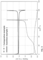
- FIG. 3 is a graph showing the initial charge / discharge characteristic of the all-solid batteries in the inventive example 1 and the comparative example.
- the battery of the present disclosure can be used as, for example, an all-solid lithium secondary battery.
Landscapes
- Chemical & Material Sciences (AREA)
- Chemical Kinetics & Catalysis (AREA)
- Electrochemistry (AREA)
- General Chemical & Material Sciences (AREA)
- Engineering & Computer Science (AREA)
- Inorganic Chemistry (AREA)
- Manufacturing & Machinery (AREA)
- Materials Engineering (AREA)
- Physics & Mathematics (AREA)
- Condensed Matter Physics & Semiconductors (AREA)
- General Physics & Mathematics (AREA)
- Secondary Cells (AREA)
- Battery Electrode And Active Subsutance (AREA)
- Conductive Materials (AREA)
- Composite Materials (AREA)
Description
- The present disclosure relates to an anode material and a battery using the same.
-
Patent Literature 1 discloses an all-solid battery including a solid electrolyte formed of a halide including indium. Patent Literature 2 and 3 discloses solid electrolyte material formed of lithium metal halide comprising yttrium. Patent Literature 4 discloses anode active material in which solid electrolyte comprising a metal fluoride is formed on the surface of lithium titanium oxide particles. Non-PatentLiterature 1 and 2 discloses ternary halides of the A3MX6 type. -
- Patent Literature 1:
Japanese Patent Application Publication No. 2006-244734 - Patent Literature 2:
EP 3 736 827 A1 - Patent Literature 3:
WO 2018/025582 A1 - Patent Literature 4:
KR 2015 0055890 A - Non-Patent Literature 1: A. Bohnsack et al., Z. anorg. allg. Chem. 1997, 623, 1352-1356.
- Non-Patent Literature 2: A. Bohnsack et al., Z. anorg. allg. Chem. 1997, 623, 1067-1073.
- An object of the present disclosure is to improve charge / discharge efficiency of a battery.
- The present disclosure provides an anode material comprising:
- anode active material particles, wherein the anode active material particles include at least one selected from the group consisting of indium metal, a lithium alloy, titanium oxide, and lithium titanate; and
- first solid electrolyte particles,
- wherein
- the first solid electrolyte particles include Li, M, and X, and do not include sulfur;
- the first solid electrolyte particles are a material represented by the following composition formula (1):
LiαMβXγ Formula (1)
- where α, β, and γ are each independently a value greater than 0,
- M is at least one selected from the group consisting of metalloid elements and metal elements other than Li, and M includes yttrium;
- X is at least one selected from the group consisting of Cl, Br, and I;
- a volume ratio Vn representing a volume of the anode active material particles to the total volume of the anode active material particles and the first solid electrolyte particles is not less than 0.3 and not more than 0.95; and
- the anode active material particles are an active material capable of storing and releasing lithium ions at a potential with respect to lithium of not less than 0.27 V.
- According to the present disclosure, the charge / discharge efficiency of the battery can be improved.
-
-
FIG. 1 shows a cross-sectional view of abattery 1000 in a second embodiment. -
FIG. 2 is a graph showing reduction potential with respect to Li of a halide solid electrolyte in the inventive example 4. -
FIG. 3 is a graph showing an initial charge / discharge characteristic of all-solid batteries in the inventive example 1 and the comparative example. - Hereinafter, embodiments of the present disclosure will be described with reference to the drawings.
- The anode material in the first embodiment includes an anode active material and a first solid electrolyte material in the form of particles.
- The first solid electrolyte material is a material represented by the following composition formula (1):
LiαMβXγ Formula (1)
where - α, β, and γ are each independently a value greater than 0;
- M includes at least one selected from the group consisting of metalloid elements and metal elements other than Li, and M includes yttrium; and
- X is at least one selected from the group consisting of Cl, Br, and I.
- The anode active material particles are an active material capable of storing and releasing lithium ions at a potential with respect to lithium of not less than 0.27 V.
- According to the above configuration, charge / discharge efficiency of a battery can be improved.
-
FIG. 2 is a graph showing reduction potential with respect to a Li reference potential of a halide. - The halide is reduced at a Li reference potential of not more than 0.27 V. The reduction can be suppressed by using an anode active material capable of storing and releasing Li ions at a potential with respect to Li of not less than 0.27 V. Thereby, the charge! discharge efficiency can be improved.
- The term "metalloid element" used in the present specification means at least one selected from the group consisting of B, Si, Ge, As, Sb, and Te.
- The term "metal element" used in the present specification includes:
- (i) all elements included in
Groups 1 to 12 of the periodic table (except for hydrogen); and - (ii) all elements included in Groups 13 to 16 of the periodic table (except for B, Si, Ge, As, Sb, Te, C, N, P, O, S, and Se).
- In other words, each of the metal elements becomes a cation when the metal element forms an inorganic compound with a halogen compound.
- In the composition formula (1), M includes Y (namely, yttrium). The first solid electrolyte material includes Y as the metal element M.
- According to the above configuration, the ionic conductivity of the first solid electrolyte material can be further improved. Thereby, the charge / discharge efficiency of the battery can be further improved.
- The first solid electrolyte material including Y may be, for example, a compound represented by the composition formula LiaMebYcX6 (where a + mb + 3c = 6, c > 0, Me is at least one selected from the group consisting of metalloid elements and metal elements other than Li and Y, and m is a valence of Me).
- As Me, at least one selected from the group consisting of Mg, Ca, Sr, Ba, Zn, Sc, Al, Ga, Bi, Zr, Hf, Ti, Sn, Ta, and Nb may be used.
- According to the above configuration, the ionic conductivity of the first solid electrolyte material can be further improved.
- The first solid electrolyte material may be Li3YCl6, Li3YBr6, Li2.5Y0.5Zr0.5Cl6, or Li3YBr2Cl2I2.
- According to the above configuration, the ionic conductivity of the first solid electrolyte material can be further improved.
- The first solid electrolyte material may be a material represented by the following composition formula (A1):
Li6-3dYdX6 Formula (A1)
where, in the composition formula (A1), X is two or more kinds of elements selected from the group consisting of Cl, Br, and I. - In the composition formula (A1), 0 < d < 2 is satisfied.
- According to the above configuration, the ionic conductivity of the first solid electrolyte material can be further improved. Thereby, the charge / discharge efficiency of the battery can be further improved.
- The first solid electrolyte material may be a material represented by the following composition formula (A2):
Li3YX6 Formula (A2)
where, in the composition formula (A2), X is two or more kinds of elements selected from the group consisting of Cl, Br, and I. - In other words, d = 1 may be satisfied in the composition formula (A1).
- According to the above configuration, the ionic conductivity of the first solid electrolyte material can be further improved. Thereby, the charge / discharge efficiency of the battery can be further improved.
- The first solid electrolyte material may be a material represented by the following composition formula (A3):
Li3-3δY1+δCl6 Formula (A3)
where, in the composition formula (A3), 0 < δ ≤ 0.15 is satisfied. - According to the above configuration, the ionic conductivity of the first solid electrolyte material can be further improved. Thereby, the charge / discharge efficiency of the battery can be further improved.
- The first solid electrolyte material may be a material represented by the following composition formula (A4):
L13-3δY1+δBr6 Formula (A4)
where, in the composition formula (A4), 0 < δ ≤ 0.25 is satisfied. - According to the above configuration, the ionic conductivity of the first solid electrolyte material can be further improved. Thereby, the charge / discharge efficiency of the battery can be further improved.
- The first solid electrolyte material may be a material represented by the following composition formula (A5):
Li3-3δ+aY1+δ-aMeaCl6-x-yBrxIy Formula (A5)
where, in the composition formula (A5), Me is at least one selected from the group consisting of Mg, Ca, Sr, Ba, and Zn. - In the composition formula (A5),


- According to the above configuration, the ionic conductivity of the first solid electrolyte material can be further improved. Thereby, the charge / discharge efficiency of the battery can be further improved.
- The first solid electrolyte material may be a material represented by the following composition formula (A6):
Li3-3δY1+δ-aMeaCl6-x-yBrxIy Formula (A6)
where, in the composition formula (A6), Me is at least one selected from the group consisting of Al, Sc, Ga, and Bi. - In the composition formula (A6),


- According to the above configuration, the ionic conductivity of the first solid electrolyte material can be further improved. Thereby, the charge / discharge efficiency of the battery can be further improved.
- The first solid electrolyte material may be a material represented by the following composition formula (A7):
Li3-3δ-aY1+δ-aMeaCl6-x-yBrxIy Formula (A7)
where, in the composition formula (A7), Me is at least one selected from the group consisting of Zr, Hf, and Ti. - In the composition formula (A7),


- According to the above configuration, the ionic conductivity of the first solid electrolyte material can be further improved. Thereby, the charge / discharge efficiency of the battery can be further improved.
- The first solid electrolyte material may be a material represented by the following composition formula (A8):
Li3-3δ-2aY1+δ-aMeaCl6-x-yBrxIy Formula (A8)
where Me is at least one selected from the group consisting of Ta and Nb. - In the composition formula (A8),


- According to the above configuration, the ionic conductivity of the first solid electrolyte material can be further improved. Thereby, the charge / discharge efficiency of the battery can be further improved.
- As the first solid electrolyte material, for example, Li3YX6, Li2MgX4, Li2FeX4, Li(Al, Ga, In)X4, or Li3(Al, Ga, In)X6 may be used.
- The anode active material includes a material having a property of storing and releasing lithium ions at a potential with respect to Li of not less than 0.27 V.
- The anode active material the anode active material particles include at least one selected from the group consisting ofindium metal, a lithium alloy, titanium oxide, and lithium titanate. Examples thereof include Li4Ti5O12, LiTi2O4, and TiO2.
- The anode active material may include a titanium oxide or In (indium).
- According to the above configuration, the charge / discharge efficiency of the battery can be further improved.
- The anode active material may include lithium titanate.
- According to the above configuration, the charge / discharge efficiency of the battery can be further improved.
- The anode material in the first embodiment includes anode
active material particles 104 and firstsolid electrolyte particles 105, as shown inFIG. 1 . - In addition, the shape of each of the first
solid electrolyte particles 105 is not limited. An example of the shape of each of the firstsolid electrolyte particles 105 is an acicular shape, an acicular shape, or an elliptically spherical shape. For example, the shape of each of the firstsolid electrolyte particles 105 may be particulate. - The median diameter of the anode
active material particles 104 may be not less than 0.1 µm and not more than 100 µm. If the median diameter of the anodeactive material particles 104 is less than 0.1 µm, the anodeactive material particles 104 and the firstsolid electrolyte particles 105 do not disperse well in the anode, so that the charge / discharge characteristic of the battery may be decreased. If the median diameter of the anodeactive material particles 104 is more than 100 µm, the rate at which lithium diffuses in the anodeactive material particles 104 may be decreased. As a result, it may be difficult to operate the battery at a high output. - The median diameter of the anode
active material particles 104 may be larger than the median diameter of the firstsolid electrolyte particles 105. Thereby, a good dispersion state of the anodeactive material particles 104 and the firstsolid electrolyte particles 105 can be formed. - In the anode material in the first embodiment, the first
solid electrolyte particles 105 and the anodeactive material particles 104 may be in contact with each other, as shown inFIG. 1 . - In addition, the anode material in the first embodiment may include a plurality of the first
solid electrolyte particles 105 and a plurality of the anodeactive material particles 104. - In addition, in the anode material in the first embodiment, the content of the first
solid electrolyte particles 105 may be the same as or different from the content of the anodeactive material particles 104. - The first solid electrolyte material in the first embodiment may be manufactured by the following method, for example.
- In consideration of the composition ratio of the product, binary halide raw material powders are prepared. For example, for synthesis of Li3YCl6, LiCl and YCl3 are prepared at a molar ratio of 3:1.
- At this time, by selecting the kinds of the raw material powders, the elements "M", "Me", and "X" in the above composition formulas can be determined. In addition, by adjusting the raw material powders, the blending ratio, and the synthesis process, the values of "α", "β", "γ", "d", "δ", "a", "x", and "y" are determined.
- The raw material powders are mixed well. Next, the raw material powders are ground by a mechanochemical milling method. In this way, the raw material powders react to provide the first solid electrolyte material. Alternatively, the raw material powders may be mixed well, and then, sintered in vacuum to provide the first solid electrolyte material.
- Thereby, the above-mentioned solid electrolyte material including a crystal phase is provided.
- The configuration of the crystal phase (namely, the crystal structure) in the solid electrolyte material may be determined by selecting the reaction method and reaction conditions of the raw material powders.
- Hereinafter, the second embodiment will be described. The description which has been set forth in the first embodiment is omitted as appropriate.
-
FIG. 1 shows a cross-sectional view of abattery 1000 in the second embodiment. - The
battery 1000 in the second embodiment comprises acathode 101, anelectrolyte layer 102, and ananode 103. - The
electrolyte layer 102 is disposed between thecathode 101 and theanode 103. - The
anode 103 includes the anode material in the first embodiment. - According to the above configuration, the charge / discharge efficiency of the battery can be improved.
- The halide is reduced at a Li reference potential of not more than 0.27 V. The reduction can be suppressed by using an anode active material capable of storing and releasing Li ions at a potential with respect to Li of not less than 0.27 V. Thereby, the charge! discharge efficiency can be improved.
- In the
anode 103, a volume ratio Vn representing a volume of the anodeactive material particles 104 to the total volume of the anodeactive material particles 104 and the firstsolid electrolyte particles 105 is not less than 0.3 and not more than 0.95. If the volume ratio Vn is less than 0.3, it may be difficult to ensure a sufficient energy density of the battery. On the other hand, if the volume ratio Vn is more than 0.95, it may be difficult to operate the battery at a high output. - The thickness of the
anode 103 is not less than 10 µm and not more than 500 µm. If the thickness of the anode is less than 10 µm, it may be difficult to ensure a sufficient energy density of the battery. In addition, if the thickness of the anode is more than 500 µm, operation at high output may be difficult. - The
cathode 101 includes a material having a property of storing and releasing metal ions (for example, lithium ions). Thecathode 101 may include a cathode active material. - Examples of the cathode active material include:
- lithium-containing transition metal oxides (for example, Li(NiCoAl)O2, Li(NiCoMn)O2, or LiCoO2);
- transition metal fluorides;
- polyanion materials;
- fluorinated polyanion materials;
- transition metal sulfides;
- transition metal oxysulfides; and
- transition metal oxynitrides.
- In particular, if a lithium-containing transition metal oxide is used as the cathode active material, reduction in manufacturing cost can be achieved and an average discharge voltage can be increased.
- The
cathode 101 may include a solid electrolyte material. According to the above configuration, conductivity of lithium ions inside thecathode 101 is increased to allow the operation at a high output. - The solid electrolyte material may be a halide solid electrolyte, a sulfide solid electrolyte, an oxide solid electrolyte, a polymer solid electrolyte, or a complex hydride solid electrolyte.
- As the halide solid electrolyte, for example, the materials exemplified as the above-mentioned first solid electrolyte material may be used.
- As the sulfide solid electrolyte, for example, Li2S-P2S5, Li2S-SiS2, Li2S-B2S3, Li2S-GeS2, Li3.25Ge0.25P0.75S4, or Li10GeP2S12 may be used. In addition, LiX (X: F, Cl, Br, I), Li2O, MOq, LipMOq (M: any of P, Si, Ge, B, Al, Ga, In, Fe, or Zn) (p, q: natural number) may be added thereto.
- As the oxide solid electrolyte, for example,
- a NASICON solid electrolyte such as LiTi2(PO4)3 and its element substitution products;
- a (LaLi)TiO3-based perovskite solid electrolyte;
- a LISICON solid electrolyte such as Li14ZnGe4O16, Li4SiO4, or LiGeO4 and their element substitution products;
- a garnet solid electrolyte such as Li7La3Zr2O12 and its element substitution products;
- Li3N and its H substitution products;
- Li3PO4 and its N substitution products;
- glass using a Li-B-O compound such as LiBO2 or Li3BO3 as the base thereof to which Li2SO4 or Li2CO3 has been added; or
- glass ceramics
- may be used.
- As the polymer solid electrolyte, for example, a compound of a polymer compound and a lithium salt can be used. The polymer compound may have an ethylene oxide structure. Since the polymer electrolyte having an ethylene oxide structure can include a large amount of lithium salt, the ionic conductivity can be further increased. As the lithium salt, LiPF6, LiBF4, LiSbF6, LiAsF6, LiSO3CF3, LiN(SO2CF3)2, LiN(SO2C2F5)2, LiN(SO2CF3)(SO2C4F9), or LiC(SO2CF3)3 may be used. As the lithium salt, one lithium salt selected from these may be used alone. Alternatively, a mixture of two or more kinds of lithium salts selected from these may be used as the lithium salt.
- As the complex hydride solid electrolyte, for example, LiBH4-LiI or LiBH4-P2S5 may be used.
- The median diameter of the cathode active material particles may be not less than 0.1 µm and not more than 100 µm. If the median diameter of the cathode active material is less than 0.1 µm, a possibility that the cathode active material particles and the solid electrolyte material fail to form a good dispersion state in the
cathode 101 arises. Thereby, the charge / discharge characteristic of the battery is decreased. On the other hand, if the median diameter of the cathode active material is larger than 100 µm, diffusion of lithium in the cathode active material particles is made slow. As a result, it may be difficult to operate the battery at a high output. - The median diameter of the cathode active material particles may be larger than the median diameter of the solid electrolyte material. Thereby, a good dispersion state of the cathode active material particles and the solid electrolyte material can be formed.
- In the
cathode 101, a volume ratio Vp representing a volume of the cathode active material particles to the total volume of the cathode active material particles and the solid electrolyte material may be not less than 0.3 and not more than 0.95. If the volume ratio Vp is less than 0.3, it may be difficult to ensure a sufficient energy density of the battery. On the other hand, if the volume ratio Vp is more than 0.95, it may be difficult to operate the battery at a high output. - The thickness of the
cathode 101 may be not less than 10 µm and not more than 500 µm. If the thickness of the cathode is less than 10 µm, it may be difficult to ensure a sufficient energy density of the battery. In addition, if the thickness of the cathode is more than 500 µm, it may be difficult to operate at a high output. - The cathode active material may be coated. As the coating material, a material having low electronic conductivity may be used. An oxide material or an oxide solid electrolyte can be used as the coating material.
- As the oxide material, for example, SiO2, Al2O3, TiO2, B2O3, Nb2O5, WO3, or ZrO2 may be used. Examples of the oxide solid electrolyte include:
- Li-Nb-O compounds such as LiNbOs;
- Li-B-O compounds such as LiBO2 or LisBOs;
- Li-Al-O compounds such as LiAlO2;
- Li-Si-O compounds such as Li4SiO4;
- Li2SO4;
- Li-Ti-O compounds such as Li4Ti5O12;
- Li-Zr-O compounds such as Li2ZrO3;
- Li-Mo-O compounds such as Li2MoO3;
- Li-V-O compounds such as LiV2O5; and
- Li-W-O compounds such as Li2WO4.
- The oxide solid electrolyte has high ionic conductivity and high potential stability. For this reason, the charge! discharge efficiency can be further improved by using an oxide solid electrolyte.
- As the solid electrolyte material included in the
electrolyte layer 102, the above-described materials (for example, the halide solid electrolyte, the sulfide solid electrolyte, the oxide solid electrolyte, the polymer solid electrolyte, the complex hydride solid electrolyte, etc.) may be used. - The
electrolyte layer 102 may include a solid electrolyte material as a main component. In other words, theelectrolyte layer 102 may include the solid electrolyte material, for example, at a weight ratio of not less than 50% (not less than 50% by weight) with respect to theentire electrolyte layer 102. - According to the above configuration, the charge / discharge characteristic of the battery can be further improved.
- In addition, the
electrolyte layer 102 may include the solid electrolyte material, for example, at a weight ratio of not less than 70% (not less than 70% by weight) with respect to theentire electrolyte layer 102. - According to the above configuration, the charge / discharge characteristic of the battery can be further improved.
- The
electrolyte layer 102 may further include inevitable impurities. Theelectrolyte layer 102 may include the starting materials used for the synthesis of the solid electrolyte material. Theelectrolyte layer 102 may include by-products or decomposition products generated when the solid electrolyte material is synthesized. - The weight ratio of the solid electrolyte material included in the
electrolyte layer 102 to theelectrolyte layer 102 may be substantially 1. "The weight ratio is substantially 1" means that the weight ratio calculated without considering the inevitable impurities that may be included in theelectrolyte layer 102 is 1. In other words, theelectrolyte layer 102 may be composed only of a solid electrolyte material. - According to the above configuration, the charge / discharge characteristic of the battery can be further improved.
- As described above, the
electrolyte layer 102 may be composed only of a solid electrolyte material. - The
electrolyte layer 102 may include two or more kinds of the materials described as the solid electrolyte material. For example, theelectrolyte layer 102 may include the first solid electrolyte material and the sulfide solid electrolyte material. - The thickness of the
electrolyte layer 102 may be not less than 1 µm and not more than 300 µm. If the thickness of theelectrolyte layer 102 is less than 1 µm, the possibility that thecathode 101 and theanode 103 are short-circuited increases. In addition, if the thickness of theelectrolyte layer 102 is more than 300 µm, it may be difficult to operate at a high output. - At least one of the
cathode 101, theelectrolyte layer 102, and theanode 103 may include a binder for the purpose of improving adhesion between the particles. The binder is used in order to improve the binding property of the material which forms the electrode. - An example of the material of the binder is poly(vinylidene fluoride), polytetrafluoroethylene, polyethylene, polypropylene, aramid resin, polyamide, polyimide, polyamideimide, polyacrylonitrile, polyacrylic acid, methyl polyacrylate ester, ethyl polyacrylate ester, hexyl polyacrylate ester, polymethacrylic acid, methyl polymethacrylate ester, ethyl polymethacrylate ester, hexyl polymethacrylate ester, polyvinyl acetate, polyvinylpyrrolidone, polyether, polyethersulfone, hexafluoropolypropylene, styrene butadiene rubber, or carboxymethylcellulose.
- As the binder, a copolymer of two or more kinds of materials selected from the group consisting of tetrafluoroethylene, hexafluoroethylene, hexafluoropropylene, perfluoroalkyl vinyl ether, vinylidene fluoride, chlorotrifluoroethylene, ethylene, propylene, pentafluoropropylene, fluoromethyl vinyl ether, acrylic acid, and hexadiene can be used.
- Two or more kinds of the binders may be used.
- At least one of the
cathode 101 and theanode 103 may include a conductive agent for the purpose of increasing the electronic conductivity. - An example of the conductive agent is
- graphite such as natural graphite or artificial graphite;
- carbon black such as acetylene black or ketjen black;
- a conductive fiber such as a carbon fiber or a metal fiber;
- carbon fluoride;
- metal powder such as aluminum;
- conductive whiskers such as zinc oxide or potassium titanate;
- a conductive metal oxide such as titanium oxide; or
- a conductive polymer compound such as polyaniline, polypyrrole, or polythiophene.
- Cost reduction can be achieved by using a carbon conductive agent.
- An example of the shape of the battery in the second embodiment is a coin, a cylinder, a prism, a sheet, a button, a flat type, or a stacking structure.
- Hereinafter, details of the present disclosure will be described with reference to inventive examples and comparative examples.
- In an argon glove box having a dew point of -60°C or less, raw material powders LiCl and YCl3 were prepared at a molar ratio of LiCl : YCl3 = 3:2. Subsequently, milling processing was performed at 600 rpm for 25 hours using a planetary ball mill (manufactured by Fritsch, type P-7) to provide a powder of the first solid electrolyte material Li3YCl6 according to the inventive example 1.
- In an argon glove box having a dew point of -60°C or less, Li2S and P2S5 were prepared at a molar ratio of Li2S : P2S5 = 75:25. These were ground and mixed in a mortar. Subsequently, milling processing was performed at 510 rpm for 10 hours using a planetary ball mill (manufactured by Fritsch, type P-7) to provide a glassy solid electrolyte. The glassy solid electrolyte was heat-treated at 270°C for 2 hours in an inert atmosphere. In this way, a glass-ceramic sulfide solid electrolyte material Li2S-P2S5 was provided.
- In an argon glove box, the first solid electrolyte material of the inventive example 1, the anode active material Li4Ti5O12, and a conductive agent VGCF were prepared at a weight ratio of 28.3 : 66.5 : 5.7. By mixing these in an agate mortar, the anode material of the inventive example 1 was produced.
- The anode active material Li4Ti5O12 is an active material capable of storing and releasing lithium ions at a potential with respect to lithium of 1.5 V. This value was measured by the following method.
- In other words, in an insulating outer cylinder, 40 mg of the anode material, 100 mg of the solid electrolyte material, and Li foil were stacked in this order. This was press-molded at a pressure of 360 MPa to produce a stacking structure. Next, stainless steel current collectors were placed on the upper and lower parts of the stacking structure, and current collector leads were attached to the current collectors. Finally, an insulating ferrule was used to block and seal the inside of the insulating outer cylinder from the outside air atmosphere. In this way, a reduction potential measurement cell was produced.
- Measurement of store / release potential of the anode active material Li4Ti5O12 was performed under the following conditions. The reduction potential measurement cell was placed in a thermostatic chamber at 25°C. Li store / release potential was measured by charging and discharging at a Li reference potential within a range of 1 V to 2.5 V by a constant current charge / discharge measurement.
- In an insulating outer cylinder, 40 mg of the anode material and 80 mg of the sulfide solid electrolyte material of the inventive example 1 were stacked in this order. This was pressure-molded at a pressure of 360 MPa to produce a stacking structure composed of an anode and an electrolyte layer.
- Next, a metal In (thickness: 200 µm) was stacked on the surface of the solid electrolyte layer opposite to the other surface which was in contact with the anode. This was pressure-molded at a pressure of 80 MPa to produce a stacking structure composed of a cathode, the solid electrolyte layer, and the anode.
- Next, stainless steel current collectors were placed on the upper and lower parts of the stacking structure, and current collector leads were attached to the current collectors.
- Finally, an insulating ferrule was used to block and seal the inside of the insulating outer cylinder from the outside air atmosphere. In this way, a battery according to the inventive example 1 was produced.
- In an argon glove box with a dew point of -60°C or lower, raw material powders LiBr and YBr3 were prepared at a molar ratio of LiBr : YBr3 = 3:2. Subsequently, milling processing was performed at 600 rpm for 25 hours using a planetary ball mill (manufactured by Fritsch, type P-7) to provide a powder of the first solid electrolyte material Li3YBr6.
- A secondary battery of the inventive example 2 was produced in the same manner as in the inventive example 1, except that the first solid electrolyte material of the inventive example 2 was used for the anode.
- In an argon glove box with a dew point of -60°C or lower, raw material powders LiCl, YCl3, and ZrCl4 were prepared at a molar ratio of LiCl : YCl3 : ZrCl4 = 2.5 : 0.5 : 0.5. Subsequently, milling processing was performed at 600 rpm for 25 hours using a planetary ball mill (manufactured by Fritsch, type P-7) to provide a powder of the first solid electrolyte material Li2.5Y0.5Zr0.5Cl6.
- A secondary battery was produced in the same manner as in the inventive example 1, except that the first solid electrolyte material of the inventive example 3 was used for the anode.
- In an argon glove box with a dew point of -60°C or lower, raw material powders LiBr, LiCl, Lil, YCl3, and YBr3 were prepared at a molar ratio of LiBr : LiCl : Lil : YCl3 : YBr3 = 1:1:4:1:1. Subsequently, milling processing was performed at 600 rpm for 25 hours using a planetary ball mill (manufactured by Fritsch, type P-7) to provide a powder of the first solid electrolyte material Li3YBr2Cl2I2.
- A secondary battery was produced in the same manner as in the inventive example 1, except that the first solid electrolyte material of the inventive example 4 was used for the anode.
- In an argon glove box, the first solid electrolyte material Li3YCl6 of the inventive example 1 and Li(NiCoMn)O2 (hereinafter, referred to as NCM) were prepared at a weight ratio of 30:70. By mixing these in an agate mortar, the cathode material of the example 5 was produced.
- In an insulating outer cylinder, 40 mg of the cathode material of the example 5 and 80 mg of the sulfide solid electrolyte material of the inventive example 1 were stacked in this order. This was pressure-molded at a pressure of 360 MPa to produce a stacking structure composed of a cathode and an electrolyte layer.
- Next, a metal In (thickness: 200 µm) was stacked on the surface of the solid electrolyte layer opposite to the other surface which was in contact with the cathode. This was pressure-molded at a pressure of 80 MPa to produce a stacking structure composed of the cathode, the solid electrolyte layer, and an anode.
- The metal In stores and releases lithium ions at a potential with respect to lithium of 0.62 V. This value was measured in the same manner as in the inventive example 1.
- Next, stainless steel current collectors were arranged on the upper and lower parts of the stacking structure, and current collector leads were attached to the current collectors.
- Finally, an insulating ferrule was used to block and seal the inside of the insulating outer cylinder from the outside air atmosphere. In this way, a battery according to the example 5 was produced.
- In an argon glove box, the first solid electrolyte material of the inventive example 1 and graphite, which was an anode active material, were prepared at a weight ratio of 60:40. By mixing these with an agate mortar, the anode material of the comparative example was produced.
- Graphite stores and releases lithium ions at a potential with respect to lithium of 0.1 V. This value was measured in the same manner as in the inventive example 1.
- A secondary battery according to the comparative example was produced in the same manner as in the inventive example 1, except that the anode material of the comparative example was used for the anode.
- A charge / discharge test was conducted as below, using each of the batteries of the inventive examples 1 to 4.
- The battery was disposed in a thermostatic chamber at 25°C.
- The battery was charged with a constant current at a current value of 70 µA, and the charge was terminated at a potential with respect to Li of 1.0 V.
- Next, the battery was discharged at a current value of 70 µA and the discharge was terminated at a potential with respect to Li of 2.5 V.
- Using the battery of the example 5, a charge / discharge test was performed as below.
- The battery was disposed in a thermostatic chamber at 25°C.
- The battery was charged with a constant current at a current value of 70 µA and the charge was terminated at a potential with respect to Li of 4.2 V.
- Next, the battery was discharged at a current value of 70 µA and the discharge was terminated at a potential with respect to Li of 2.5 V.
- A charge / discharge test was performed under the following conditions, using the battery of the comparative example.
- The battery was disposed in a thermostatic chamber at 25°C. The battery was charged with a constant current at a current value of 70 µA, and the charge was terminated at a potential with respect to Li of 0.0 V.
- Next, the battery was discharged at a current value of 70 µA and the discharge was terminated at a potential with respect to Li of 2.5 V.
- On the basis of the above charge / discharge results, the initial charge / discharge efficiency (= initial discharge capacity / initial charge capacity) of each of the batteries of the inventive examples 1 to 5 and the comparative example were provided. The results are shown in Table 1 below.
[Table 1] Anode layer Charge / discharge efficiency (%) Anode active material Solid electrolyte Inventive Example 1 Li4Ti5O12 Li3YCl6 99.1 Inventive Example 2 Li4Ti5O12 Li3YBr6 97.3 Inventive Example 3 Li4Ti5O12 Li2.5Y0.5Zr0.5Cl6 93.4 Inventive Example 4 Li4Ti5O12 Li3YBr2Cl2I2 96.6 Example 5 In - 89.1 Comparative Example Graphite Li3YCl6 77.9 -
FIG. 3 is a graph showing the initial charge / discharge characteristic of the all-solid batteries in the inventive example 1 and the comparative example. - From the results of the inventive example 1 and the comparative example shown in
FIG. 3 and Table 1, it was confirmed that the reduction of the halide solid electrolyte was suppressed by using the active material capable of storing and releasing Li ions at a potential with respect to Li of not less than 0.27 V for the anode, and that the charge / discharge efficiency was improved. - From the results of the inventive examples 1 to 4 and the comparative example shown in Table 1, a similar effect was confirmed for the halide solid electrolytes other than Li3YCl6 and for the anode material other than Li4Ti5O12.
- The battery of the present disclosure can be used as, for example, an all-solid lithium secondary battery.
-
- 1000
- Battery
- 101
- Cathode
- 102
- Electrolyte layer
- 103
- Anode
- 104
- Anode active material particle
- 105
- First solid electrolyte particle
Claims (7)
- An anode material, comprising:anode active material particles (104), wherein the anode active material particles (104) include at least one selected from the group consisting of indium metal, a lithium alloy, titanium oxide, and lithium titanate; andfirst solid electrolyte particles (105),whereinthe first solid electrolyte particles (105) include Li, M, and X, and do not include sulfur;the first solid electrolyte particles (105) are a material represented by the following composition formula (1):
LiαMβXγ Formula (1)
where α, β, and γ are each independently a value greater than 0,M is at least one selected from the group consisting of metalloid elements and metal elements other than Li, and M includes yttrium;X is at least one selected from the group consisting of Cl, Br, and I;a volume ratio Vn representing a volume of the anode active material particles to the total volume of the anode active material particles (104) and the first solid electrolyte particles (105) is not less than 0.3 and not more than 0.95; andthe anode active material particles (104) are an active material capable of storing and releasing lithium ions at a potential with respect to lithium of not less than 0.27 V, measured as described in the specification. - The electrode material according to claim 1, wherein
the first solid electrolyte particles (105) are a material reduced at a potential with respect to lithium of not more than 0.27 V. - The anode material according to claim 1, wherein
the first solid electrolyte particles (105) are a material that is
Li3YCl6,
Li3YBr6,
Li2.5Y0.5Zr0.5Cl6,
or
Li3YBr2Cl2I2.
- The anode material according to any one of claims 1 to 3, wherein
the anode active material particles (104) include at least one selected from the group consisting of titanium oxide and indium. - The anode material according to claim 4, wherein
the anode active material particles (104) include lithium titanate. - A battery (1000) comprising:an anode (103) comprising the anode material according to any one of claims 1 to 5;a cathode (101); andan electrolyte layer (102) provided between the cathode (101) and the anode (103),wherein the thickness of the anode (103) is not less than 10 µm and not more than 500 µm.
- The battery (1000) according to claim 6, wherein
the electrolyte layer (102) includes the first solid electrolyte particles (105).
Applications Claiming Priority (2)
| Application Number | Priority Date | Filing Date | Title |
|---|---|---|---|
| JP2018011529 | 2018-01-26 | ||
| PCT/JP2018/045587 WO2019146295A1 (en) | 2018-01-26 | 2018-12-12 | Negative electrode material and battery using same |
Publications (3)
| Publication Number | Publication Date |
|---|---|
| EP3745498A1 EP3745498A1 (en) | 2020-12-02 |
| EP3745498A4 EP3745498A4 (en) | 2021-03-10 |
| EP3745498B1 true EP3745498B1 (en) | 2023-09-13 |
Family
ID=67395343
Family Applications (1)
| Application Number | Title | Priority Date | Filing Date |
|---|---|---|---|
| EP18902104.1A Active EP3745498B1 (en) | 2018-01-26 | 2018-12-12 | Negative electrode material and battery using same |
Country Status (5)
| Country | Link |
|---|---|
| US (1) | US11777088B2 (en) |
| EP (1) | EP3745498B1 (en) |
| JP (1) | JP7199038B2 (en) |
| CN (1) | CN111566848B (en) |
| WO (1) | WO2019146295A1 (en) |
Families Citing this family (27)
| Publication number | Priority date | Publication date | Assignee | Title |
|---|---|---|---|---|
| CN114846642A (en) * | 2019-12-27 | 2022-08-02 | 松下知识产权经营株式会社 | Electrode and battery |
| JP7780729B2 (en) * | 2020-03-05 | 2025-12-05 | パナソニックIpマネジメント株式会社 | Cathode Materials and Batteries |
| KR102595966B1 (en) | 2020-04-14 | 2023-11-01 | 세인트-고바인 세라믹스 앤드 플라스틱스, 인크. | Ion conductive material, electrolyte comprising ion conductive material, and method of forming |
| US11522217B2 (en) | 2020-04-14 | 2022-12-06 | Saint-Gobain Ceramics & Plastics, Inc. | Electrolyte material and methods of forming |
| WO2021217045A1 (en) | 2020-04-23 | 2021-10-28 | Saint-Gobain Ceramics & Plastics, Inc. | Ion conductive layer and methods of forming |
| CN115428214B (en) | 2020-04-23 | 2025-08-12 | 圣戈本陶瓷及塑料股份有限公司 | Ion conductive layer and forming method thereof |
| WO2021250985A1 (en) * | 2020-06-08 | 2021-12-16 | パナソニックIpマネジメント株式会社 | Solid electrolyte material, and battery in which same is used |
| JP7318140B2 (en) | 2020-08-07 | 2023-07-31 | サン-ゴバン セラミックス アンド プラスティクス,インコーポレイティド | Electrolyte material and forming method |
| CN112713266B (en) * | 2020-12-30 | 2022-05-27 | 蜂巢能源科技有限公司 | Negative electrode slurry and application thereof |
| JP7692271B2 (en) * | 2021-01-18 | 2025-06-13 | Tdk株式会社 | Active material layer, negative electrode and all-solid-state battery |
| JP7617267B2 (en) | 2021-02-23 | 2025-01-17 | エルジー エナジー ソリューション リミテッド | Secondary battery, battery pack, and automobile |
| JP7722827B2 (en) * | 2021-03-26 | 2025-08-13 | Tdk株式会社 | Electrode active material layer, electrode, all-solid-state battery |
| CN117121125A (en) * | 2021-04-07 | 2023-11-24 | 松下知识产权经营株式会社 | Solid electrolyte material and battery using the solid electrolyte material |
| JP7784632B2 (en) * | 2021-04-13 | 2025-12-12 | パナソニックIpマネジメント株式会社 | Negative electrode material and battery using the same |
| CN117063318A (en) * | 2021-04-13 | 2023-11-14 | 松下知识产权经营株式会社 | Battery |
| KR102637203B1 (en) | 2021-05-17 | 2024-02-19 | 세인트-고바인 세라믹스 앤드 플라스틱스, 인크. | Electrolyte materials and formation methods |
| WO2022254796A1 (en) * | 2021-05-31 | 2022-12-08 | パナソニックIpマネジメント株式会社 | Electrode material and battery |
| EP4354530A4 (en) | 2021-06-11 | 2025-05-21 | Panasonic Intellectual Property Management Co., Ltd. | ELECTRODE MATERIAL AND BATTERY |
| JPWO2022264554A1 (en) * | 2021-06-18 | 2022-12-22 | ||
| JP7801691B2 (en) * | 2021-08-19 | 2026-01-19 | パナソニックIpマネジメント株式会社 | Electrodes and batteries |
| CN118369782A (en) * | 2021-12-10 | 2024-07-19 | 松下知识产权经营株式会社 | Electrode materials, electrodes and batteries |
| WO2024042861A1 (en) * | 2022-08-23 | 2024-02-29 | パナソニックIpマネジメント株式会社 | Solid electrolyte, battery, method for manufacturing solid electrolyte, and method for manufacturing battery |
| JPWO2024071221A1 (en) * | 2022-09-28 | 2024-04-04 | ||
| JPWO2024096110A1 (en) | 2022-11-04 | 2024-05-10 | ||
| CN116190574A (en) * | 2023-02-21 | 2023-05-30 | 有研(广东)新材料技术研究院 | A composite negative electrode suitable for all-solid-state batteries and its preparation method |
| WO2025069384A1 (en) * | 2023-09-29 | 2025-04-03 | 国立大学法人名古屋工業大学 | Battery |
| KR20260015898A (en) | 2023-09-29 | 2026-02-03 | 국립대학법인 나고야공업대학 | battery |
Family Cites Families (11)
| Publication number | Priority date | Publication date | Assignee | Title |
|---|---|---|---|---|
| JP3531866B2 (en) * | 2000-07-28 | 2004-05-31 | 独立行政法人 科学技術振興機構 | Thin-film solid lithium ion secondary battery |
| CN1260848C (en) * | 2002-03-28 | 2006-06-21 | Tdk株式会社 | Lithium secondary battery |
| JP5108205B2 (en) | 2005-02-28 | 2012-12-26 | 国立大学法人静岡大学 | All solid-state lithium secondary battery |
| JP4575487B2 (en) * | 2008-10-30 | 2010-11-04 | 株式会社オハラ | Lithium ion secondary battery and manufacturing method thereof |
| JP2012104280A (en) * | 2010-11-08 | 2012-05-31 | Toyota Motor Corp | Sintered body for battery, all-solid lithium battery, and method for manufacturing sintered body for battery |
| US9099744B2 (en) * | 2011-03-31 | 2015-08-04 | Basf Se | Particulate porous carbon material and use thereof in lithium cells |
| CN104106164A (en) * | 2012-02-17 | 2014-10-15 | 索尼公司 | Secondary cell, method for manufacturing secondary cell, electrode for secondary cell, and electronic device |
| KR20150055890A (en) * | 2013-11-14 | 2015-05-22 | 주식회사 엘지화학 | Surface-Modified Anode Active Material and Method for Manufacturing The Same |
| CN115036565B (en) | 2016-08-04 | 2025-02-28 | 松下知识产权经营株式会社 | Solid electrolyte materials and batteries |
| CN107611340B (en) * | 2017-08-23 | 2020-06-12 | 柔电(武汉)科技有限公司 | Flexible all-solid-state battery and preparation method thereof |
| WO2019135347A1 (en) * | 2018-01-05 | 2019-07-11 | パナソニックIpマネジメント株式会社 | Solid electrolyte material and battery |
-
2018
- 2018-12-12 JP JP2019567905A patent/JP7199038B2/en active Active
- 2018-12-12 WO PCT/JP2018/045587 patent/WO2019146295A1/en not_active Ceased
- 2018-12-12 EP EP18902104.1A patent/EP3745498B1/en active Active
- 2018-12-12 CN CN201880085582.4A patent/CN111566848B/en active Active
-
2020
- 2020-07-16 US US16/930,415 patent/US11777088B2/en active Active
Also Published As
| Publication number | Publication date |
|---|---|
| US11777088B2 (en) | 2023-10-03 |
| EP3745498A4 (en) | 2021-03-10 |
| EP3745498A1 (en) | 2020-12-02 |
| CN111566848A (en) | 2020-08-21 |
| WO2019146295A1 (en) | 2019-08-01 |
| JP7199038B2 (en) | 2023-01-05 |
| JPWO2019146295A1 (en) | 2021-01-14 |
| CN111566848B (en) | 2024-05-10 |
| US20200350562A1 (en) | 2020-11-05 |
Similar Documents
| Publication | Publication Date | Title |
|---|---|---|
| EP3745498B1 (en) | Negative electrode material and battery using same | |
| EP3745518B1 (en) | Battery | |
| US12431500B2 (en) | Cathode material and battery | |
| EP3745519B1 (en) | Battery | |
| EP3745504B1 (en) | Electrode material and battery | |
| US11637287B2 (en) | Positive electrode material and battery using same | |
| US12206111B2 (en) | Cathode material and battery using same | |
| EP3736830B1 (en) | Solid electrolyte material and battery | |
| EP3736892A1 (en) | Positive electrode material and battery | |
| EP3736828A1 (en) | Solid electrolyte material and battery | |
| EP3745522A1 (en) | Battery | |
| EP3736891A1 (en) | Positive electrode material and battery | |
| EP3745500A1 (en) | Battery | |
| CN111295789A (en) | Solid electrolyte material and battery | |
| US12132168B2 (en) | Battery |
Legal Events
| Date | Code | Title | Description |
|---|---|---|---|
| STAA | Information on the status of an ep patent application or granted ep patent |
Free format text: STATUS: THE INTERNATIONAL PUBLICATION HAS BEEN MADE |
|
| PUAI | Public reference made under article 153(3) epc to a published international application that has entered the european phase |
Free format text: ORIGINAL CODE: 0009012 |
|
| STAA | Information on the status of an ep patent application or granted ep patent |
Free format text: STATUS: REQUEST FOR EXAMINATION WAS MADE |
|
| 17P | Request for examination filed |
Effective date: 20200706 |
|
| AK | Designated contracting states |
Kind code of ref document: A1 Designated state(s): AL AT BE BG CH CY CZ DE DK EE ES FI FR GB GR HR HU IE IS IT LI LT LU LV MC MK MT NL NO PL PT RO RS SE SI SK SM TR |
|
| AX | Request for extension of the european patent |
Extension state: BA ME |
|
| REG | Reference to a national code |
Ref country code: DE Ipc: H01M0004131000 Ref country code: DE Ref legal event code: R079 Ref document number: 602018057735 Country of ref document: DE Free format text: PREVIOUS MAIN CLASS: H01M0004130000 Ipc: H01M0004131000 |
|
| A4 | Supplementary search report drawn up and despatched |
Effective date: 20210209 |
|
| RIC1 | Information provided on ipc code assigned before grant |
Ipc: H01M 4/485 20100101ALI20210203BHEP Ipc: H01M 4/38 20060101ALI20210203BHEP Ipc: H01M 4/131 20100101AFI20210203BHEP Ipc: H01M 10/0562 20100101ALI20210203BHEP Ipc: H01M 10/0525 20100101ALI20210203BHEP Ipc: H01M 4/62 20060101ALI20210203BHEP |
|
| DAV | Request for validation of the european patent (deleted) | ||
| DAX | Request for extension of the european patent (deleted) | ||
| GRAP | Despatch of communication of intention to grant a patent |
Free format text: ORIGINAL CODE: EPIDOSNIGR1 |
|
| STAA | Information on the status of an ep patent application or granted ep patent |
Free format text: STATUS: GRANT OF PATENT IS INTENDED |
|
| INTG | Intention to grant announced |
Effective date: 20230412 |
|
| GRAS | Grant fee paid |
Free format text: ORIGINAL CODE: EPIDOSNIGR3 |
|
| GRAA | (expected) grant |
Free format text: ORIGINAL CODE: 0009210 |
|
| STAA | Information on the status of an ep patent application or granted ep patent |
Free format text: STATUS: THE PATENT HAS BEEN GRANTED |
|
| AK | Designated contracting states |
Kind code of ref document: B1 Designated state(s): AL AT BE BG CH CY CZ DE DK EE ES FI FR GB GR HR HU IE IS IT LI LT LU LV MC MK MT NL NO PL PT RO RS SE SI SK SM TR |
|
| REG | Reference to a national code |
Ref country code: CH Ref legal event code: EP |
|
| REG | Reference to a national code |
Ref country code: DE Ref legal event code: R096 Ref document number: 602018057735 Country of ref document: DE |
|
| REG | Reference to a national code |
Ref country code: IE Ref legal event code: FG4D |
|
| REG | Reference to a national code |
Ref country code: LT Ref legal event code: MG9D |
|
| REG | Reference to a national code |
Ref country code: NL Ref legal event code: MP Effective date: 20230913 |
|
| PG25 | Lapsed in a contracting state [announced via postgrant information from national office to epo] |
Ref country code: GR Free format text: LAPSE BECAUSE OF FAILURE TO SUBMIT A TRANSLATION OF THE DESCRIPTION OR TO PAY THE FEE WITHIN THE PRESCRIBED TIME-LIMIT Effective date: 20231214 |
|
| PG25 | Lapsed in a contracting state [announced via postgrant information from national office to epo] |
Ref country code: SE Free format text: LAPSE BECAUSE OF FAILURE TO SUBMIT A TRANSLATION OF THE DESCRIPTION OR TO PAY THE FEE WITHIN THE PRESCRIBED TIME-LIMIT Effective date: 20230913 Ref country code: RS Free format text: LAPSE BECAUSE OF FAILURE TO SUBMIT A TRANSLATION OF THE DESCRIPTION OR TO PAY THE FEE WITHIN THE PRESCRIBED TIME-LIMIT Effective date: 20230913 Ref country code: NO Free format text: LAPSE BECAUSE OF FAILURE TO SUBMIT A TRANSLATION OF THE DESCRIPTION OR TO PAY THE FEE WITHIN THE PRESCRIBED TIME-LIMIT Effective date: 20231213 Ref country code: LV Free format text: LAPSE BECAUSE OF FAILURE TO SUBMIT A TRANSLATION OF THE DESCRIPTION OR TO PAY THE FEE WITHIN THE PRESCRIBED TIME-LIMIT Effective date: 20230913 Ref country code: LT Free format text: LAPSE BECAUSE OF FAILURE TO SUBMIT A TRANSLATION OF THE DESCRIPTION OR TO PAY THE FEE WITHIN THE PRESCRIBED TIME-LIMIT Effective date: 20230913 Ref country code: HR Free format text: LAPSE BECAUSE OF FAILURE TO SUBMIT A TRANSLATION OF THE DESCRIPTION OR TO PAY THE FEE WITHIN THE PRESCRIBED TIME-LIMIT Effective date: 20230913 Ref country code: GR Free format text: LAPSE BECAUSE OF FAILURE TO SUBMIT A TRANSLATION OF THE DESCRIPTION OR TO PAY THE FEE WITHIN THE PRESCRIBED TIME-LIMIT Effective date: 20231214 Ref country code: FI Free format text: LAPSE BECAUSE OF FAILURE TO SUBMIT A TRANSLATION OF THE DESCRIPTION OR TO PAY THE FEE WITHIN THE PRESCRIBED TIME-LIMIT Effective date: 20230913 |
|
| REG | Reference to a national code |
Ref country code: AT Ref legal event code: MK05 Ref document number: 1612202 Country of ref document: AT Kind code of ref document: T Effective date: 20230913 |
|
| PG25 | Lapsed in a contracting state [announced via postgrant information from national office to epo] |
Ref country code: NL Free format text: LAPSE BECAUSE OF FAILURE TO SUBMIT A TRANSLATION OF THE DESCRIPTION OR TO PAY THE FEE WITHIN THE PRESCRIBED TIME-LIMIT Effective date: 20230913 |
|
| PG25 | Lapsed in a contracting state [announced via postgrant information from national office to epo] |
Ref country code: IS Free format text: LAPSE BECAUSE OF FAILURE TO SUBMIT A TRANSLATION OF THE DESCRIPTION OR TO PAY THE FEE WITHIN THE PRESCRIBED TIME-LIMIT Effective date: 20240113 |
|
| PG25 | Lapsed in a contracting state [announced via postgrant information from national office to epo] |
Ref country code: AT Free format text: LAPSE BECAUSE OF FAILURE TO SUBMIT A TRANSLATION OF THE DESCRIPTION OR TO PAY THE FEE WITHIN THE PRESCRIBED TIME-LIMIT Effective date: 20230913 |
|
| PG25 | Lapsed in a contracting state [announced via postgrant information from national office to epo] |
Ref country code: ES Free format text: LAPSE BECAUSE OF FAILURE TO SUBMIT A TRANSLATION OF THE DESCRIPTION OR TO PAY THE FEE WITHIN THE PRESCRIBED TIME-LIMIT Effective date: 20230913 |
|
| PG25 | Lapsed in a contracting state [announced via postgrant information from national office to epo] |
Ref country code: SM Free format text: LAPSE BECAUSE OF FAILURE TO SUBMIT A TRANSLATION OF THE DESCRIPTION OR TO PAY THE FEE WITHIN THE PRESCRIBED TIME-LIMIT Effective date: 20230913 Ref country code: RO Free format text: LAPSE BECAUSE OF FAILURE TO SUBMIT A TRANSLATION OF THE DESCRIPTION OR TO PAY THE FEE WITHIN THE PRESCRIBED TIME-LIMIT Effective date: 20230913 Ref country code: IS Free format text: LAPSE BECAUSE OF FAILURE TO SUBMIT A TRANSLATION OF THE DESCRIPTION OR TO PAY THE FEE WITHIN THE PRESCRIBED TIME-LIMIT Effective date: 20240113 Ref country code: ES Free format text: LAPSE BECAUSE OF FAILURE TO SUBMIT A TRANSLATION OF THE DESCRIPTION OR TO PAY THE FEE WITHIN THE PRESCRIBED TIME-LIMIT Effective date: 20230913 Ref country code: EE Free format text: LAPSE BECAUSE OF FAILURE TO SUBMIT A TRANSLATION OF THE DESCRIPTION OR TO PAY THE FEE WITHIN THE PRESCRIBED TIME-LIMIT Effective date: 20230913 Ref country code: CZ Free format text: LAPSE BECAUSE OF FAILURE TO SUBMIT A TRANSLATION OF THE DESCRIPTION OR TO PAY THE FEE WITHIN THE PRESCRIBED TIME-LIMIT Effective date: 20230913 Ref country code: AT Free format text: LAPSE BECAUSE OF FAILURE TO SUBMIT A TRANSLATION OF THE DESCRIPTION OR TO PAY THE FEE WITHIN THE PRESCRIBED TIME-LIMIT Effective date: 20230913 Ref country code: PT Free format text: LAPSE BECAUSE OF FAILURE TO SUBMIT A TRANSLATION OF THE DESCRIPTION OR TO PAY THE FEE WITHIN THE PRESCRIBED TIME-LIMIT Effective date: 20240115 Ref country code: SK Free format text: LAPSE BECAUSE OF FAILURE TO SUBMIT A TRANSLATION OF THE DESCRIPTION OR TO PAY THE FEE WITHIN THE PRESCRIBED TIME-LIMIT Effective date: 20230913 |
|
| PG25 | Lapsed in a contracting state [announced via postgrant information from national office to epo] |
Ref country code: PL Free format text: LAPSE BECAUSE OF FAILURE TO SUBMIT A TRANSLATION OF THE DESCRIPTION OR TO PAY THE FEE WITHIN THE PRESCRIBED TIME-LIMIT Effective date: 20230913 Ref country code: IT Free format text: LAPSE BECAUSE OF FAILURE TO SUBMIT A TRANSLATION OF THE DESCRIPTION OR TO PAY THE FEE WITHIN THE PRESCRIBED TIME-LIMIT Effective date: 20230913 |
|
| REG | Reference to a national code |
Ref country code: DE Ref legal event code: R097 Ref document number: 602018057735 Country of ref document: DE |
|
| PG25 | Lapsed in a contracting state [announced via postgrant information from national office to epo] |
Ref country code: DK Free format text: LAPSE BECAUSE OF FAILURE TO SUBMIT A TRANSLATION OF THE DESCRIPTION OR TO PAY THE FEE WITHIN THE PRESCRIBED TIME-LIMIT Effective date: 20230913 |
|
| PLBE | No opposition filed within time limit |
Free format text: ORIGINAL CODE: 0009261 |
|
| STAA | Information on the status of an ep patent application or granted ep patent |
Free format text: STATUS: NO OPPOSITION FILED WITHIN TIME LIMIT |
|
| PG25 | Lapsed in a contracting state [announced via postgrant information from national office to epo] |
Ref country code: DK Free format text: LAPSE BECAUSE OF FAILURE TO SUBMIT A TRANSLATION OF THE DESCRIPTION OR TO PAY THE FEE WITHIN THE PRESCRIBED TIME-LIMIT Effective date: 20230913 |
|
| REG | Reference to a national code |
Ref country code: CH Ref legal event code: PL |
|
| 26N | No opposition filed |
Effective date: 20240614 |
|
| PG25 | Lapsed in a contracting state [announced via postgrant information from national office to epo] |
Ref country code: LU Free format text: LAPSE BECAUSE OF NON-PAYMENT OF DUE FEES Effective date: 20231212 |
|
| PG25 | Lapsed in a contracting state [announced via postgrant information from national office to epo] |
Ref country code: MC Free format text: LAPSE BECAUSE OF FAILURE TO SUBMIT A TRANSLATION OF THE DESCRIPTION OR TO PAY THE FEE WITHIN THE PRESCRIBED TIME-LIMIT Effective date: 20230913 |
|
| GBPC | Gb: european patent ceased through non-payment of renewal fee |
Effective date: 20231213 |
|
| REG | Reference to a national code |
Ref country code: BE Ref legal event code: MM Effective date: 20231231 |
|
| PG25 | Lapsed in a contracting state [announced via postgrant information from national office to epo] |
Ref country code: MC Free format text: LAPSE BECAUSE OF FAILURE TO SUBMIT A TRANSLATION OF THE DESCRIPTION OR TO PAY THE FEE WITHIN THE PRESCRIBED TIME-LIMIT Effective date: 20230913 Ref country code: LU Free format text: LAPSE BECAUSE OF NON-PAYMENT OF DUE FEES Effective date: 20231212 |
|
| REG | Reference to a national code |
Ref country code: IE Ref legal event code: MM4A |
|
| PG25 | Lapsed in a contracting state [announced via postgrant information from national office to epo] |
Ref country code: IE Free format text: LAPSE BECAUSE OF NON-PAYMENT OF DUE FEES Effective date: 20231212 |
|
| PG25 | Lapsed in a contracting state [announced via postgrant information from national office to epo] |
Ref country code: GB Free format text: LAPSE BECAUSE OF NON-PAYMENT OF DUE FEES Effective date: 20231213 |
|
| PG25 | Lapsed in a contracting state [announced via postgrant information from national office to epo] |
Ref country code: BE Free format text: LAPSE BECAUSE OF NON-PAYMENT OF DUE FEES Effective date: 20231231 |
|
| PG25 | Lapsed in a contracting state [announced via postgrant information from national office to epo] |
Ref country code: FR Free format text: LAPSE BECAUSE OF NON-PAYMENT OF DUE FEES Effective date: 20231231 |
|
| PG25 | Lapsed in a contracting state [announced via postgrant information from national office to epo] |
Ref country code: CH Free format text: LAPSE BECAUSE OF NON-PAYMENT OF DUE FEES Effective date: 20231231 |
|
| PG25 | Lapsed in a contracting state [announced via postgrant information from national office to epo] |
Ref country code: SI Free format text: LAPSE BECAUSE OF FAILURE TO SUBMIT A TRANSLATION OF THE DESCRIPTION OR TO PAY THE FEE WITHIN THE PRESCRIBED TIME-LIMIT Effective date: 20230913 |
|
| PG25 | Lapsed in a contracting state [announced via postgrant information from national office to epo] |
Ref country code: SI Free format text: LAPSE BECAUSE OF FAILURE TO SUBMIT A TRANSLATION OF THE DESCRIPTION OR TO PAY THE FEE WITHIN THE PRESCRIBED TIME-LIMIT Effective date: 20230913 Ref country code: IE Free format text: LAPSE BECAUSE OF NON-PAYMENT OF DUE FEES Effective date: 20231212 Ref country code: GB Free format text: LAPSE BECAUSE OF NON-PAYMENT OF DUE FEES Effective date: 20231213 Ref country code: FR Free format text: LAPSE BECAUSE OF NON-PAYMENT OF DUE FEES Effective date: 20231231 Ref country code: CH Free format text: LAPSE BECAUSE OF NON-PAYMENT OF DUE FEES Effective date: 20231231 Ref country code: BE Free format text: LAPSE BECAUSE OF NON-PAYMENT OF DUE FEES Effective date: 20231231 |
|
| PG25 | Lapsed in a contracting state [announced via postgrant information from national office to epo] |
Ref country code: BG Free format text: LAPSE BECAUSE OF FAILURE TO SUBMIT A TRANSLATION OF THE DESCRIPTION OR TO PAY THE FEE WITHIN THE PRESCRIBED TIME-LIMIT Effective date: 20230913 |
|
| PG25 | Lapsed in a contracting state [announced via postgrant information from national office to epo] |
Ref country code: BG Free format text: LAPSE BECAUSE OF FAILURE TO SUBMIT A TRANSLATION OF THE DESCRIPTION OR TO PAY THE FEE WITHIN THE PRESCRIBED TIME-LIMIT Effective date: 20230913 |
|
| PG25 | Lapsed in a contracting state [announced via postgrant information from national office to epo] |
Ref country code: CY Free format text: LAPSE BECAUSE OF FAILURE TO SUBMIT A TRANSLATION OF THE DESCRIPTION OR TO PAY THE FEE WITHIN THE PRESCRIBED TIME-LIMIT; INVALID AB INITIO Effective date: 20181212 |
|
| PG25 | Lapsed in a contracting state [announced via postgrant information from national office to epo] |
Ref country code: HU Free format text: LAPSE BECAUSE OF FAILURE TO SUBMIT A TRANSLATION OF THE DESCRIPTION OR TO PAY THE FEE WITHIN THE PRESCRIBED TIME-LIMIT; INVALID AB INITIO Effective date: 20181212 |
|
| PG25 | Lapsed in a contracting state [announced via postgrant information from national office to epo] |
Ref country code: TR Free format text: LAPSE BECAUSE OF FAILURE TO SUBMIT A TRANSLATION OF THE DESCRIPTION OR TO PAY THE FEE WITHIN THE PRESCRIBED TIME-LIMIT Effective date: 20230913 |
|
| PGFP | Annual fee paid to national office [announced via postgrant information from national office to epo] |
Ref country code: DE Payment date: 20251211 Year of fee payment: 8 |