EP3745419B1 - Nuclear fuel pellet having excellent compression resistance and reduced surface defect - Google Patents
Nuclear fuel pellet having excellent compression resistance and reduced surface defect Download PDFInfo
- Publication number
- EP3745419B1 EP3745419B1 EP18902048.0A EP18902048A EP3745419B1 EP 3745419 B1 EP3745419 B1 EP 3745419B1 EP 18902048 A EP18902048 A EP 18902048A EP 3745419 B1 EP3745419 B1 EP 3745419B1
- Authority
- EP
- European Patent Office
- Prior art keywords
- chamfer
- pellet
- angle
- land
- fuel
- Prior art date
- Legal status (The legal status is an assumption and is not a legal conclusion. Google has not performed a legal analysis and makes no representation as to the accuracy of the status listed.)
- Active
Links
Images


Classifications
-
- G—PHYSICS
- G21—NUCLEAR PHYSICS; NUCLEAR ENGINEERING
- G21C—NUCLEAR REACTORS
- G21C3/00—Reactor fuel elements and their assemblies; Selection of substances for use as reactor fuel elements
- G21C3/02—Fuel elements
- G21C3/04—Constructional details
- G21C3/045—Pellets
- G21C3/048—Shape of pellets
-
- G—PHYSICS
- G21—NUCLEAR PHYSICS; NUCLEAR ENGINEERING
- G21C—NUCLEAR REACTORS
- G21C3/00—Reactor fuel elements and their assemblies; Selection of substances for use as reactor fuel elements
- G21C3/02—Fuel elements
- G21C3/04—Constructional details
-
- G—PHYSICS
- G21—NUCLEAR PHYSICS; NUCLEAR ENGINEERING
- G21C—NUCLEAR REACTORS
- G21C3/00—Reactor fuel elements and their assemblies; Selection of substances for use as reactor fuel elements
- G21C3/02—Fuel elements
- G21C3/04—Constructional details
- G21C3/045—Pellets
-
- G—PHYSICS
- G21—NUCLEAR PHYSICS; NUCLEAR ENGINEERING
- G21C—NUCLEAR REACTORS
- G21C21/00—Apparatus or processes specially adapted to the manufacture of reactors or parts thereof
- G21C21/02—Manufacture of fuel elements or breeder elements contained in non-active casings
-
- G—PHYSICS
- G21—NUCLEAR PHYSICS; NUCLEAR ENGINEERING
- G21C—NUCLEAR REACTORS
- G21C3/00—Reactor fuel elements and their assemblies; Selection of substances for use as reactor fuel elements
- G21C3/02—Fuel elements
- G21C3/04—Constructional details
- G21C3/06—Casings; Jackets
-
- Y—GENERAL TAGGING OF NEW TECHNOLOGICAL DEVELOPMENTS; GENERAL TAGGING OF CROSS-SECTIONAL TECHNOLOGIES SPANNING OVER SEVERAL SECTIONS OF THE IPC; TECHNICAL SUBJECTS COVERED BY FORMER USPC CROSS-REFERENCE ART COLLECTIONS [XRACs] AND DIGESTS
- Y02—TECHNOLOGIES OR APPLICATIONS FOR MITIGATION OR ADAPTATION AGAINST CLIMATE CHANGE
- Y02E—REDUCTION OF GREENHOUSE GAS [GHG] EMISSIONS, RELATED TO ENERGY GENERATION, TRANSMISSION OR DISTRIBUTION
- Y02E30/00—Energy generation of nuclear origin
- Y02E30/30—Nuclear fission reactors
Definitions
- the present invention relates to a fuel pellet and, in particular, to a fuel pellet used in nuclear power plants and having a shape providing excellent compression resistance and excellent surface defect reduction performance.
- Nuclear fuel used in a nuclear power plant is generally composed of stacked fuel pellets inside a cladding. At this time, the fuel pellet is mainly fabricated by using UO 2 powder.
- UO 2 powder In order to improve the economic efficiency of the nuclear power plant, a high-burnup and long-term operation is considered, and accordingly, the operating environment of the nuclear power plant has become harsher, and the necessity of developing a high-performance nuclear fuel has emerged.
- a missing pellet surface occurs due to various external impacts, contacts, and the like during a manufacturing process and movement of the fabricated fuel pellet and excessive stress is concentrated on a site of the missing pellet surface, resulting in cracking of the fuel pellet.
- the cracking expands to pellet-cladding mechanical interaction (PCMI) damage, fuel pellet fracture due to fission gas agglomeration at the site of the surface defect of the fuel pellet, and the like. This has emerged as an important problem in an increasingly harsh nuclear operating environment.
- PCMI pellet-cladding mechanical interaction
- the fuel pellet is composed of: a dish at a center part; a chamfer at an end part; and a land part connecting the dish and the chamfer therethrough.
- the chamfer which is the end of the fuel pellet, serves to minimize the breakage of the fuel pellet due to contact of the end portion, by being formed at a predetermined angle.
- studies have been most greatly conducted on changing a chamfer angle of the fuel pellet.
- WO2010/037748 discloses a nuclear fuel pellet of cylindrical shape and a dish on the top and bottom surface thereof.
- the present applicant is to provide a fuel pellet that exhibits superior missing pellet surface reduction performance through a change in land width along with the chamfer angle while conducting research for the performance of reducing missing pellet surface.
- Korean Patent No. KR 10-0982664 (Registered on September 10, 2010 )
- the present invention is proposed to solve the problems as described above and has an objective to provide a fuel pellet having improved missing pellet surface reduction performance that can be used in a core of a nuclear power plant by providing a double chamfer.
- a double chamfer is provided, and a shape of a fuel pellet according to the present invention is as follows.
- the double chamfer makes a new chamfer having a small angle move to the center of a fuel pellet and flatten due to the densification of the fuel pellet while a green pellet is being sintered, thus reducing the risk of missing pellet surface.
- a land portion having a slope of a zero-degree angle should be essentially present between a dish and a primary chamfer.
- the land portion does not present, and the chamfer directly leads to the dish.
- the stress is collected at a portion where the chamfer starts in the dish, and thus there is no significant effect on reducing missing pellet surface probability.
- the amount of loss of the fuel pellet is reduced to increase power plant efficiency.
- the land portion is placed between the chamfer and the dish so that the reducing performance for missing pellet surface is improved through a change in the land portion width along with a change in the chamfer angle.
- the fuel pellet according to the present invention is excellent in reducing performance of missing pellet surface by controlling the chamfer angle and the land portion width and has a high compressive strength that can be withstood inside the cladding, thereby improving the integrity of the fuel pellet. Accordingly, there is an effect that the fuel pellet can be usefully used even in a high-burnup and long-term operating environment of a nuclear power plant.
- the fuel pellet according to the present invention is configured to include a dish, a land, and a chamfer, and has the dish the same as present in a conventional fuel pellet and improves missing pellet surface resistance by changing a double chamfer and land width.
- the fuel pellet has the double chamfer and conserves the amount of uranium loss of the fuel pellet and improves resistance to missing pellet surface.
- the fuel pellet has a primary chamfer and a secondary chamfer, as a double chamfer, thereby improving the missing pellet surface resistance by resolving a stress concentration phenomenon of a portion leading from a land portion of the conventional fuel pellet to the chamfer.
- the primary chamfer of the double chamfer has a gentler slope than the secondary chamfer.
- the primary chamfer of the double chamfer of the fuel pellet has an angle of a one-degree angle to a four-degree angle and a width of 0.3 to 1.5 mm.
- the secondary chamfer of the double chamfer of the fuel pellet has an angle of a 12-degree angle to a 25-degree angle and a width of 0.13 to 0.18 mm.
- the fuel pellet has the land portion between the double chamfer and the dish, thereby preventing abnormal stacking of the fuel pellets and reducing the concentration of the stress between the primary chamfer and the dish to improve resistance to defects, wherein the land has a width of 0.3 to 1.5 mm.
- the green pellet of the present invention shrinks in the width and angle while becoming the fuel pellet after sintering, but since the variation thereof is not large, the ranges of chamfer angle and the land portion width of the green pellet and the fuel pellet are considered to be the same.
- the angle of the primary chamfer of the fuel pellet having the double chamfer is lower than a 1-degree angle, the secondary chamfer becomes completely flat after sintering, so there is no effect of improving missing pellet surface resistance.
- the angle of the primary chamfer of the fuel pellet having the double chamfer is greater than a 4-degree angle, a portion between the primary chamfer and the secondary chamfer acts as an edge, so it is easy to cause damage at a site of the portion.
- the land portion of a predetermined width is necessarily included.
- the fuel pellet according to the present invention is prepared by the following method.
- Step 1 is to add a lubricant to the UO 2 -based powder and mix the lubricant and the UO 2 -based powder, and then to crush, dry, and sieve a mixture to make a mixed powder.
- Step 2 is a process of providing a green pellet at a constant pressure by putting the mixed powder prepared by the preparing method of step 1 into a mold die. At this time, the pressure is 2,500 to 3,000 kgf.
- the compaction density is low when the pressure is less than 2,500 kgf, and a defect may occur at the end portion of the green pellet when the pressure is more than 3,000 kgf.
- Step 3 is a process of preparing the fuel pellet having improved missing pellet surface resistance by maintaining the green pellet, obtained by the preparing method of step 2, in a gas atmosphere of reducing hydrogen gas at a temperature of 1600 to 1850°C for two to 4 hours.
- the sintering time when the sintering time is less than 2 hours, the densification by sintering is not completely achieved, so that the primary chamfer is difficult to flatten, and when the sintering time is greater than 4 hours, the sintering is excessive, whereby the primary chamfer is completely flattened, thereby being unable to properly play its original role.
- a commercially available fuel pellet used in a nuclear power plant was used.
- the commercial fuel pellet has a single chamfer, and no secondary chamfer is present.
- a fuel pellet having the double chamfer without the land portion was prepared and used.
- the fuel pellets of embodiments 1 to 6 prepared according to the present invention exhibited a lower weight reduction amount due to a smaller amount of fractured fuel pellets than the commercially available fuel pellets shown in comparative example 1.
- the weight reduction amount of the fuel pellets of embodiments 1 to 6 prepared according to the present invention exhibited lower than that of the fuel pellet having the double chamfer without the land portion shown in comparative example 2.
- the cross-sections of the fuel pellets after fractured are investigated, it may be seen that the fuel pellets having the double chamfers are less damaged. Therefore, it may be seen that the missing pellet surface resistance was improved in the fuel pellets of embodiments 1 to 6 in which the fuel pellets inside the cladding were simulated.
- the double chamfer makes the new chamfer having a small angle move to the center of the fuel pellet and flatten due to the densification of the fuel pellet while a green pellet is being sintered, reducing the risk of missing pellet surface.
- a land portion having a slope of a zero-degree angle should be essentially present between the dish and the primary chamfer.
- the land portion does not present, and the chamfer directly leads to the dish.
- the stress is collected at a portion where the chamfer starts from the dish, and thus there is no significant effect on reducing the missing pellet surface.
- by adding the land portion there is an effect that the amount of loss of the fuel pellet is reduced to increase power plant efficiency.
- the present invention aims such that the land portion is placed between the chamfer and the dish, whereby the reduction performance of missing pellet surface-is enhanced through a change in the land width and chamfer angle.
Landscapes
- Engineering & Computer Science (AREA)
- Physics & Mathematics (AREA)
- Plasma & Fusion (AREA)
- General Engineering & Computer Science (AREA)
- High Energy & Nuclear Physics (AREA)
- Manufacturing & Machinery (AREA)
- Powder Metallurgy (AREA)
- Monitoring And Testing Of Nuclear Reactors (AREA)
Description
- The present invention relates to a fuel pellet and, in particular, to a fuel pellet used in nuclear power plants and having a shape providing excellent compression resistance and excellent surface defect reduction performance.
- Nuclear fuel used in a nuclear power plant is generally composed of stacked fuel pellets inside a cladding. At this time, the fuel pellet is mainly fabricated by using UO2 powder. In order to improve the economic efficiency of the nuclear power plant, a high-burnup and long-term operation is considered, and accordingly, the operating environment of the nuclear power plant has become harsher, and the necessity of developing a high-performance nuclear fuel has emerged.
- In particular, a missing pellet surface occurs due to various external impacts, contacts, and the like during a manufacturing process and movement of the fabricated fuel pellet and excessive stress is concentrated on a site of the missing pellet surface, resulting in cracking of the fuel pellet. Conventionally, the cracking expands to pellet-cladding mechanical interaction (PCMI) damage, fuel pellet fracture due to fission gas agglomeration at the site of the surface defect of the fuel pellet, and the like. This has emerged as an important problem in an increasingly harsh nuclear operating environment.
- As such, many studies have been conducted to improve the performance of reducing missing pellet surface in the nuclear fuel of the nuclear power plant, and in particular, many studies have been conducted on the shape of a fuel pellet that can secure the integrity of nuclear fuel in a high-burnup and long-term operation. The fuel pellet is composed of: a dish at a center part; a chamfer at an end part; and a land part connecting the dish and the chamfer therethrough. In particular, the chamfer, which is the end of the fuel pellet, serves to minimize the breakage of the fuel pellet due to contact of the end portion, by being formed at a predetermined angle. However, currently, as many missing pellet surface are still generated in commercial fuel pellets, studies have been most greatly conducted on changing a chamfer angle of the fuel pellet.
-
WO2010/037748 discloses a nuclear fuel pellet of cylindrical shape and a dish on the top and bottom surface thereof. - However, since it is difficult to improve the performance of reducing missing pellet surface only by changing the chamfer angle, and it is also difficult to compensate, in consideration of power plant efficiency, for the loss of the fuel pellet according to the change in the angle, changes in dishes, lands, and the like are also being studied.
- Therefore, the present applicant is to provide a fuel pellet that exhibits superior missing pellet surface reduction performance through a change in land width along with the chamfer angle while conducting research for the performance of reducing missing pellet surface.
- Korean Patent No.
KR 10-0982664 (Registered on September 10, 2010 - Accordingly, the present invention is proposed to solve the problems as described above and has an objective to provide a fuel pellet having improved missing pellet surface reduction performance that can be used in a core of a nuclear power plant by providing a double chamfer.
- In order to achieve the above objective, a double chamfer is provided, and a shape of a fuel pellet according to the present invention is as follows.
- The double chamfer makes a new chamfer having a small angle move to the center of a fuel pellet and flatten due to the densification of the fuel pellet while a green pellet is being sintered, thus reducing the risk of missing pellet surface. At this time, a land portion having a slope of a zero-degree angle should be essentially present between a dish and a primary chamfer. In conventional double chamfer-related patents, the land portion does not present, and the chamfer directly leads to the dish. At this time, the stress is collected at a portion where the chamfer starts in the dish, and thus there is no significant effect on reducing missing pellet surface probability. In addition, by adding the land portion, the amount of loss of the fuel pellet is reduced to increase power plant efficiency.
- Therefore, in the present invention, the land portion is placed between the chamfer and the dish so that the reducing performance for missing pellet surface is improved through a change in the land portion width along with a change in the chamfer angle.
- As described above, the fuel pellet according to the present invention is excellent in reducing performance of missing pellet surface by controlling the chamfer angle and the land portion width and has a high compressive strength that can be withstood inside the cladding, thereby improving the integrity of the fuel pellet. Accordingly, there is an effect that the fuel pellet can be usefully used even in a high-burnup and long-term operating environment of a nuclear power plant.
-
-
FIG. 1 is a front sectional view of an upper portion of a fuel pellet according to the present invention. -
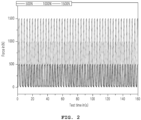
FIG. 2 is a schematic view of a compression fatigue test in the present invention. -
FIG. 3 shows sectional views of the fuel pellet after the compression fatigue test in the present invention. - Specific structures or functional descriptions presented in embodiments of the present invention are exemplified for a purpose of describing the embodiments according to a concept of the present invention, and the embodiments according to the concept of the present invention may be implemented in various forms. In addition, the present invention should not be construed as being limited to the embodiments described herein but should be understood to include all modifications, equivalents, or substitutes included in the spirit and scope thereof.
- Hereinafter, the present invention will be described in detail with reference to the accompanying drawings.
- The fuel pellet according to the present invention is configured to include a dish, a land, and a chamfer, and has the dish the same as present in a conventional fuel pellet and improves missing pellet surface resistance by changing a double chamfer and land width.
- In addition, the fuel pellet has the double chamfer and conserves the amount of uranium loss of the fuel pellet and improves resistance to missing pellet surface.
- In addition, the fuel pellet has a primary chamfer and a secondary chamfer, as a double chamfer, thereby improving the missing pellet surface resistance by resolving a stress concentration phenomenon of a portion leading from a land portion of the conventional fuel pellet to the chamfer.
- In addition, in the fuel pellet, the primary chamfer of the double chamfer has a gentler slope than the secondary chamfer.
- In addition, the primary chamfer of the double chamfer of the fuel pellet has an angle of a one-degree angle to a four-degree angle and a width of 0.3 to 1.5 mm.
- In addition, the secondary chamfer of the double chamfer of the fuel pellet has an angle of a 12-degree angle to a 25-degree angle and a width of 0.13 to 0.18 mm.
- In addition, the fuel pellet has the land portion between the double chamfer and the dish, thereby preventing abnormal stacking of the fuel pellets and reducing the concentration of the stress between the primary chamfer and the dish to improve resistance to defects, wherein the land has a width of 0.3 to 1.5 mm.
- The green pellet of the present invention shrinks in the width and angle while becoming the fuel pellet after sintering, but since the variation thereof is not large, the ranges of chamfer angle and the land portion width of the green pellet and the fuel pellet are considered to be the same.
- In addition, when the angle of the primary chamfer of the fuel pellet having the double chamfer is lower than a 1-degree angle, the secondary chamfer becomes completely flat after sintering, so there is no effect of improving missing pellet surface resistance. In addition, when the angle of the primary chamfer of the fuel pellet having the double chamfer is greater than a 4-degree angle, a portion between the primary chamfer and the secondary chamfer acts as an edge, so it is easy to cause damage at a site of the portion.
- In addition, when there is no land portion of the fuel pellet having the double chamfer, since damage occurs between the primary chamfer and the dish, the land portion of a predetermined width is necessarily included.
- The fuel pellet according to the present invention is prepared by the following method.
-
Step 1 is to add a lubricant to the UO2-based powder and mix the lubricant and the UO2-based powder, and then to crush, dry, and sieve a mixture to make a mixed powder. -
Step 2 is a process of providing a green pellet at a constant pressure by putting the mixed powder prepared by the preparing method ofstep 1 into a mold die. At this time, the pressure is 2,500 to 3,000 kgf. - In addition, in the case of the fuel pellet having the double chamfer, the compaction density is low when the pressure is less than 2,500 kgf, and a defect may occur at the end portion of the green pellet when the pressure is more than 3,000 kgf.
-
Step 3 is a process of preparing the fuel pellet having improved missing pellet surface resistance by maintaining the green pellet, obtained by the preparing method ofstep 2, in a gas atmosphere of reducing hydrogen gas at a temperature of 1600 to 1850°C for two to 4 hours. - In addition, in the case of the fuel pellet having the double chamfer, when the sintering time is less than 2 hours, the densification by sintering is not completely achieved, so that the primary chamfer is difficult to flatten, and when the sintering time is greater than 4 hours, the sintering is excessive, whereby the primary chamfer is completely flattened, thereby being unable to properly play its original role.
- Hereinafter, the present invention consisting of the steps described above will be described in more detail by taking various embodiments as examples.
- Specific details of the fuel pellet according to the present invention are summarized in Table 1 below.
[Table 1] Classification Degree angle (°) Volume (mm3) Uranium loss rate (%) Primary chamfer Secondary chamfer Primary chamfer height Secondary chamfer height Land width Embodiment-1 2 13 511.7 0.13 0.38 0.35 8.57 Embodiment-2 4 13 511.3 0.17 0.38 0.50 9.17 Embodiment-3 2 18 510.6 0.13 0.66 0.75 11.17 Embodiment-4 4 18 509.7 0.17 0.66 1.00 11.77 Embodiment-5 2 23 509.8 0.13 0.94 1.25 12.07 Embodiment-6 4 23 508.9 0.17 0.94 1.50 12.47 Comparative example-1 - - Comparative example-2 2 13 510.9 0.13 0.38 - 12.33 - As a comparative example 1, a commercially available fuel pellet used in a nuclear power plant was used. The commercial fuel pellet has a single chamfer, and no secondary chamfer is present.
- As a comparative example 2, a fuel pellet having the double chamfer without the land portion was prepared and used.
- In order to investigate the reduction performance of missing pellet surface resistance fuel pellet for present invention, according to the present invention, a low cycle compression fatigue test was performed by simulating stacking of the fuel pellets.
- After the fuel pellets of
embodiments 1 to 6 were prepared by the above preparing process, the situation in which the fuel pellets were stacked in the cladding was simulated, and the tests were each performed 50 cycles by increasing the pressure to 500 to 1500 N (Newton). The stacking of the fuel pellets was performed in two cases, a normal state and an abnormal state. - After the low cycle compression fatigue test, an amount of the weight loss of the fuel pellets in the case of fracture was measured and shown in Table 2 except for the fuel pellets in which no fracture occurred.
[Table 2] Before test After test Amount of weight change Embodiment-1 5.8679 5.7521 0.1158 Embodiment-2 5.8075 5.4637 0.3438 Embodiment-3 5.8101 5.8101 0.0000 Embodiment-4 5.8524 5.6533 0.1991 Embodiment-5 5.8309 5.6084 0.2225 Embodiment-6 5.8428 5.7069 0.1359 Comparative example-1 5.4564 4.9744 0.4820 Comparative example-2 5.7866 5.0537 0.7329 - As shown in Table 2, the fuel pellets of
embodiments 1 to 6 prepared according to the present invention exhibited a lower weight reduction amount due to a smaller amount of fractured fuel pellets than the commercially available fuel pellets shown in comparative example 1. In addition, the weight reduction amount of the fuel pellets ofembodiments 1 to 6 prepared according to the present invention exhibited lower than that of the fuel pellet having the double chamfer without the land portion shown in comparative example 2. In addition, when the cross-sections of the fuel pellets after fractured are investigated, it may be seen that the fuel pellets having the double chamfers are less damaged. Therefore, it may be seen that the missing pellet surface resistance was improved in the fuel pellets ofembodiments 1 to 6 in which the fuel pellets inside the cladding were simulated. - In order to find out maximum compressive strength applied to the fuel pellet according to the present invention, a compression test was performed. The compression test was performed at a rate of 1 mm/min until fracture of the fuel pellet after holding the fuel pellet for about 10 seconds at 50 N of preload. As shown in Table 3, the maximum compressive strength is higher in the fuel pellets having the double chamfers of
embodiments 1 to 6 than in the commercially available fuel pellets presented in comparative example 1, indicating that the compressive strength characteristics were improved.[Table 3] Maximum compressive strength (MPa) Embodiment-1 105.0 Embodiment-2 115.8 Embodiment-3 123.8 Embodiment-4 123.1 Embodiment-5 119.7 Embodiment-6 120.2 Comparative example-1 83.0 Comparative example-2 76.6 - The double chamfer makes the new chamfer having a small angle move to the center of the fuel pellet and flatten due to the densification of the fuel pellet while a green pellet is being sintered, reducing the risk of missing pellet surface. At this time, a land portion having a slope of a zero-degree angle should be essentially present between the dish and the primary chamfer. In conventional double chamfer-related patents, the land portion does not present, and the chamfer directly leads to the dish. At this time, the stress is collected at a portion where the chamfer starts from the dish, and thus there is no significant effect on reducing the missing pellet surface. In addition, by adding the land portion, there is an effect that the amount of loss of the fuel pellet is reduced to increase power plant efficiency.
- Therefore, the present invention aims such that the land portion is placed between the chamfer and the dish, whereby the reduction performance of missing pellet surface-is enhanced through a change in the land width and chamfer angle.
Claims (10)
- A nuclear fuel pellet having excellent compression resistance and a reduced missing pellet surface, pellet being a cylindrical shape and comprising, on each of a top surface and a bottom surface thereof:a dish configured as a spherical groove shape having a predetermined curved surface at a center;a land configured as a horizontal annular shape along a rim of the dish; anda chamfer configured as a shape in which a corner is chamfered at a predetermined angle along a rim of the land, wherein the chamfer comprises:a primary chamfer adjacent to the rim of the land; anda secondary chamfer configured as a shape additionally chamfered along a rim of the primary chamfer.
- The pellet of claim 1, wherein an angle made by the primary chamfer and a horizontal plane is smaller than an angle made by the secondary chamfer and the horizontal plane.
- The pellet of claim 2, wherein the angle made by the primary chamfer and the horizontal plane is a one-degree angle to a 4-degree angle.
- The pellet of claim 2, wherein the angle made by the secondary chamfer and the horizontal plane is a 14-degree angle to a 25-degree angle.
- The pellet of claim 1, wherein width of the land is 0.3 to 1.5 mm.
- A preparing method of a nuclear fuel pellet having excellent compression resistance and a reduced missing pellet surface, the method comprising:preparing a mixed powder by mixing UO2-based powder and lubricant powder;preparing a green pellet by compressing and molding the mixed powder to 2,500 to 3,000 kgf; andsintering the green pellet with a reducing gas atmosphere at 1600 to 1850°C for 2-4 hours,wherein in the preparing the green pellet by compressing and molding the mixed powder, to prepare the green pellet into a fuel pellet having a cylindrical shape, each of the top surface and the bottom surface of the fuel pellet is prepared to comprise:a dish configured as a spherical groove shape having a predetermined curved surface in a center;a land configured as a horizontal annular shape along an edge of the dish; anda chamfer configured as a shape in which a corner of the surface is chamfered at a predetermined angle along a rim of the land, wherein the chamfer comprises:a primary chamfer adjacent to the rim of the land; anda secondary chamfer configured as a shape in which the corner of the surface is additionally chamfered along the rim of the primary chamfer.
- The method of claim 6, wherein, in the preparing the green pellet by compressing and molding the mixed powder, an angle made by the primary chamfer and a horizontal plane is configured to be smaller than an angle made by the secondary chamfer and the horizontal plane.
- The method of claim 7, wherein an angle made by the primary chamfer and the horizontal plane is a 1-degree angle to a 4-degree angle.
- The method of claim 7, wherein an angle made by the secondary chamfer and the horizontal plane is a 14-degree angle to a 25-degree angle.
- The method of claim 6, wherein width of the land is 0.3 to 1.5 mm.
Applications Claiming Priority (2)
| Application Number | Priority Date | Filing Date | Title |
|---|---|---|---|
| KR1020180008764A KR102123234B1 (en) | 2018-01-24 | 2018-01-24 | Nuclear fuel pellet having excellent resistace to compression fracture amd being reduced surface chipping |
| PCT/KR2018/008637 WO2019146858A1 (en) | 2018-01-24 | 2018-07-30 | Nuclear fuel pellet having excellent compression resistance and reduced surface defect |
Publications (3)
| Publication Number | Publication Date |
|---|---|
| EP3745419A1 EP3745419A1 (en) | 2020-12-02 |
| EP3745419A4 EP3745419A4 (en) | 2021-10-27 |
| EP3745419B1 true EP3745419B1 (en) | 2023-08-23 |
Family
ID=67395029
Family Applications (1)
| Application Number | Title | Priority Date | Filing Date |
|---|---|---|---|
| EP18902048.0A Active EP3745419B1 (en) | 2018-01-24 | 2018-07-30 | Nuclear fuel pellet having excellent compression resistance and reduced surface defect |
Country Status (6)
| Country | Link |
|---|---|
| US (1) | US20210050120A1 (en) |
| EP (1) | EP3745419B1 (en) |
| KR (1) | KR102123234B1 (en) |
| CN (1) | CN111630611A (en) |
| PL (1) | PL3745419T3 (en) |
| WO (1) | WO2019146858A1 (en) |
Families Citing this family (1)
| Publication number | Priority date | Publication date | Assignee | Title |
|---|---|---|---|---|
| CN119400459B (en) * | 2024-10-28 | 2025-11-04 | 中广核研究院有限公司 | Nuclear fuel elements and nuclear fuel rods |
Family Cites Families (10)
| Publication number | Priority date | Publication date | Assignee | Title |
|---|---|---|---|---|
| CA1003127A (en) * | 1973-05-29 | 1977-01-04 | Canadian General Electric Company Limited | Nuclear fuel element with end pellet relief |
| JPS5332297A (en) * | 1976-09-06 | 1978-03-27 | Toshiba Corp | Fuel element |
| CA1250965A (en) * | 1985-11-07 | 1989-03-07 | Canadian General Electric Company Limited | Nuclear fuel system |
| JPH0517594U (en) * | 1991-08-21 | 1993-03-05 | 原子燃料工業株式会社 | Nuclear fuel pellets |
| KR100293482B1 (en) * | 1998-09-08 | 2001-07-12 | 이종훈 | Method of Manufacturing Nuclear Fuel Sintered |
| JP4320383B2 (en) * | 1999-01-18 | 2009-08-26 | 三菱重工業株式会社 | Nuclear fuel pellets and fuel rods loaded with the same nuclear fuel pellets |
| DE19910379C1 (en) * | 1999-03-09 | 2000-06-29 | Siemens Ag | Fuel element, especially for PWR, has thickened cladding tube lower end forming at least lower portion of fuel pellet column support |
| FR2817385B1 (en) * | 2000-11-30 | 2005-10-07 | Framatome Anp | PASTILLE OF NUCLEAR FUEL OXIDE AND PENCIL COMPRISING A STACK OF SUCH PELLETS |
| WO2010038109A1 (en) * | 2008-09-30 | 2010-04-08 | Areva Np | Nuclear reactor green and sintered fuel pellets, corresponding fuel rod and fuel assembly |
| KR100982664B1 (en) | 2008-12-31 | 2010-09-17 | 한국수력원자력 주식회사 | Method for the sintered annular nuclear fuel pellet |
-
2018
- 2018-01-24 KR KR1020180008764A patent/KR102123234B1/en active Active
- 2018-07-30 CN CN201880087291.9A patent/CN111630611A/en not_active Withdrawn
- 2018-07-30 US US16/963,281 patent/US20210050120A1/en not_active Abandoned
- 2018-07-30 EP EP18902048.0A patent/EP3745419B1/en active Active
- 2018-07-30 PL PL18902048.0T patent/PL3745419T3/en unknown
- 2018-07-30 WO PCT/KR2018/008637 patent/WO2019146858A1/en not_active Ceased
Also Published As
| Publication number | Publication date |
|---|---|
| PL3745419T3 (en) | 2024-03-11 |
| EP3745419A4 (en) | 2021-10-27 |
| CN111630611A (en) | 2020-09-04 |
| KR102123234B1 (en) | 2020-06-16 |
| EP3745419A1 (en) | 2020-12-02 |
| US20210050120A1 (en) | 2021-02-18 |
| KR20190090199A (en) | 2019-08-01 |
| WO2019146858A1 (en) | 2019-08-01 |
Similar Documents
| Publication | Publication Date | Title |
|---|---|---|
| CN102217003A (en) | Nuclear reactor green and sintered fuel pellets, corresponding fuel rod and fuel assembly | |
| KR101082060B1 (en) | Method for the sintered annular nuclear fuel pellet | |
| KR20230006061A (en) | Nuclear fuel pellet laminate structure having enhanced thermal conductivity and method for manufacturing the same | |
| EP3745419A1 (en) | Nuclear fuel pellet having excellent compression resistance and reduced surface defect | |
| CN105924169B (en) | One kind is with waste and old UO2Powder is the high density UO of raw material2Pellet preparation method | |
| CN106082192B (en) | Preparation method of artificial graphite powder for high-temperature gas cooled reactor nuclear fuel element and graphite powder | |
| JP4700806B2 (en) | Nuclear fuel pellets | |
| EP3624137A1 (en) | Method for the manufacture of pelletized nuclear ceramic fuel | |
| JP3919929B2 (en) | NUCLEAR PELLET, ITS MANUFACTURING METHOD, FUEL ELEMENT AND FUEL ASSEMBLY | |
| RU89904U1 (en) | Nuclear reactor fuel rod | |
| KR20110089801A (en) | Sintered body of uranium dioxide with nickel oxide and aluminum oxide added and method of manufacturing the same | |
| US20210202115A1 (en) | Nuclear-fuel sintered pellets based on oxide in which fine precipitate material is dispersed in circumferential direction and method of manufacturing same | |
| CN117373703A (en) | A kind of large grain UO2 pellet for high fuel consumption fuel rod and its preparation method | |
| KR100982664B1 (en) | Method for the sintered annular nuclear fuel pellet | |
| KR101029616B1 (en) | Method for manufacturing annular fuel sintered body by rod insertion sintering | |
| KR100521638B1 (en) | Uranium dioxide fuel containing SiO2-CaO-Cr2O3 and thereof method | |
| CN112897988B (en) | A kind of polyvinyl butyral solution bonding lead oxide ceramic for solid oxygen control and preparation method thereof | |
| RU2421834C1 (en) | Manufacturing method of ceramic fuel pellets for fuel elements of nuclear reactor | |
| CN121769020A (en) | Electrode sheet and preparation method thereof | |
| US6984344B2 (en) | Production process of a composite nuclear fuel material composed of (U, Pu)O2 aggregates dispersed in a UO2 matrix | |
| KR100973498B1 (en) | Manufacturing method of large grain sulphate and its sintered body | |
| RU2360308C1 (en) | Method of fuel pellet production for nuclear fuel elements | |
| JP2001124883A (en) | Method for producing nuclear fuel pellets | |
| RU2396611C1 (en) | Method of preparing nuclear fuel pellets | |
| RU2499304C1 (en) | Method of making nuclear fuel tablets |
Legal Events
| Date | Code | Title | Description |
|---|---|---|---|
| STAA | Information on the status of an ep patent application or granted ep patent |
Free format text: STATUS: THE INTERNATIONAL PUBLICATION HAS BEEN MADE |
|
| PUAI | Public reference made under article 153(3) epc to a published international application that has entered the european phase |
Free format text: ORIGINAL CODE: 0009012 |
|
| STAA | Information on the status of an ep patent application or granted ep patent |
Free format text: STATUS: REQUEST FOR EXAMINATION WAS MADE |
|
| 17P | Request for examination filed |
Effective date: 20200821 |
|
| AK | Designated contracting states |
Kind code of ref document: A1 Designated state(s): AL AT BE BG CH CY CZ DE DK EE ES FI FR GB GR HR HU IE IS IT LI LT LU LV MC MK MT NL NO PL PT RO RS SE SI SK SM TR |
|
| AX | Request for extension of the european patent |
Extension state: BA ME |
|
| DAV | Request for validation of the european patent (deleted) | ||
| DAX | Request for extension of the european patent (deleted) | ||
| RIN1 | Information on inventor provided before grant (corrected) |
Inventor name: CHOI, MIN YOUNG Inventor name: NA, YEON-SOO Inventor name: LIM, KWANG-YOUNG Inventor name: JUNG, TAE SIK Inventor name: LEE, SEUNG-JAE Inventor name: MOK, YONG KYOON Inventor name: YOO, JONG SUNG |
|
| STAA | Information on the status of an ep patent application or granted ep patent |
Free format text: STATUS: EXAMINATION IS IN PROGRESS |
|
| A4 | Supplementary search report drawn up and despatched |
Effective date: 20210929 |
|
| RIC1 | Information provided on ipc code assigned before grant |
Ipc: G21C 21/02 20060101ALI20210923BHEP Ipc: G21C 3/04 20060101AFI20210923BHEP |
|
| 17Q | First examination report despatched |
Effective date: 20211012 |
|
| GRAP | Despatch of communication of intention to grant a patent |
Free format text: ORIGINAL CODE: EPIDOSNIGR1 |
|
| STAA | Information on the status of an ep patent application or granted ep patent |
Free format text: STATUS: GRANT OF PATENT IS INTENDED |
|
| INTG | Intention to grant announced |
Effective date: 20230302 |
|
| GRAS | Grant fee paid |
Free format text: ORIGINAL CODE: EPIDOSNIGR3 |
|
| GRAA | (expected) grant |
Free format text: ORIGINAL CODE: 0009210 |
|
| STAA | Information on the status of an ep patent application or granted ep patent |
Free format text: STATUS: THE PATENT HAS BEEN GRANTED |
|
| AK | Designated contracting states |
Kind code of ref document: B1 Designated state(s): AL AT BE BG CH CY CZ DE DK EE ES FI FR GB GR HR HU IE IS IT LI LT LU LV MC MK MT NL NO PL PT RO RS SE SI SK SM TR |
|
| REG | Reference to a national code |
Ref country code: GB Ref legal event code: FG4D |
|
| REG | Reference to a national code |
Ref country code: CH Ref legal event code: EP |
|
| REG | Reference to a national code |
Ref country code: IE Ref legal event code: FG4D |
|
| REG | Reference to a national code |
Ref country code: DE Ref legal event code: R096 Ref document number: 602018056199 Country of ref document: DE |
|
| REG | Reference to a national code |
Ref country code: LT Ref legal event code: MG9D |
|
| REG | Reference to a national code |
Ref country code: NL Ref legal event code: MP Effective date: 20230823 |
|
| REG | Reference to a national code |
Ref country code: AT Ref legal event code: MK05 Ref document number: 1603566 Country of ref document: AT Kind code of ref document: T Effective date: 20230823 |
|
| PG25 | Lapsed in a contracting state [announced via postgrant information from national office to epo] |
Ref country code: GR Free format text: LAPSE BECAUSE OF FAILURE TO SUBMIT A TRANSLATION OF THE DESCRIPTION OR TO PAY THE FEE WITHIN THE PRESCRIBED TIME-LIMIT Effective date: 20231124 |
|
| PG25 | Lapsed in a contracting state [announced via postgrant information from national office to epo] |
Ref country code: IS Free format text: LAPSE BECAUSE OF FAILURE TO SUBMIT A TRANSLATION OF THE DESCRIPTION OR TO PAY THE FEE WITHIN THE PRESCRIBED TIME-LIMIT Effective date: 20231223 |
|
| PG25 | Lapsed in a contracting state [announced via postgrant information from national office to epo] |
Ref country code: SE Free format text: LAPSE BECAUSE OF FAILURE TO SUBMIT A TRANSLATION OF THE DESCRIPTION OR TO PAY THE FEE WITHIN THE PRESCRIBED TIME-LIMIT Effective date: 20230823 Ref country code: RS Free format text: LAPSE BECAUSE OF FAILURE TO SUBMIT A TRANSLATION OF THE DESCRIPTION OR TO PAY THE FEE WITHIN THE PRESCRIBED TIME-LIMIT Effective date: 20230823 Ref country code: PT Free format text: LAPSE BECAUSE OF FAILURE TO SUBMIT A TRANSLATION OF THE DESCRIPTION OR TO PAY THE FEE WITHIN THE PRESCRIBED TIME-LIMIT Effective date: 20231226 Ref country code: NO Free format text: LAPSE BECAUSE OF FAILURE TO SUBMIT A TRANSLATION OF THE DESCRIPTION OR TO PAY THE FEE WITHIN THE PRESCRIBED TIME-LIMIT Effective date: 20231123 Ref country code: NL Free format text: LAPSE BECAUSE OF FAILURE TO SUBMIT A TRANSLATION OF THE DESCRIPTION OR TO PAY THE FEE WITHIN THE PRESCRIBED TIME-LIMIT Effective date: 20230823 Ref country code: LV Free format text: LAPSE BECAUSE OF FAILURE TO SUBMIT A TRANSLATION OF THE DESCRIPTION OR TO PAY THE FEE WITHIN THE PRESCRIBED TIME-LIMIT Effective date: 20230823 Ref country code: LT Free format text: LAPSE BECAUSE OF FAILURE TO SUBMIT A TRANSLATION OF THE DESCRIPTION OR TO PAY THE FEE WITHIN THE PRESCRIBED TIME-LIMIT Effective date: 20230823 Ref country code: IS Free format text: LAPSE BECAUSE OF FAILURE TO SUBMIT A TRANSLATION OF THE DESCRIPTION OR TO PAY THE FEE WITHIN THE PRESCRIBED TIME-LIMIT Effective date: 20231223 Ref country code: HR Free format text: LAPSE BECAUSE OF FAILURE TO SUBMIT A TRANSLATION OF THE DESCRIPTION OR TO PAY THE FEE WITHIN THE PRESCRIBED TIME-LIMIT Effective date: 20230823 Ref country code: GR Free format text: LAPSE BECAUSE OF FAILURE TO SUBMIT A TRANSLATION OF THE DESCRIPTION OR TO PAY THE FEE WITHIN THE PRESCRIBED TIME-LIMIT Effective date: 20231124 Ref country code: FI Free format text: LAPSE BECAUSE OF FAILURE TO SUBMIT A TRANSLATION OF THE DESCRIPTION OR TO PAY THE FEE WITHIN THE PRESCRIBED TIME-LIMIT Effective date: 20230823 Ref country code: AT Free format text: LAPSE BECAUSE OF FAILURE TO SUBMIT A TRANSLATION OF THE DESCRIPTION OR TO PAY THE FEE WITHIN THE PRESCRIBED TIME-LIMIT Effective date: 20230823 |
|
| PG25 | Lapsed in a contracting state [announced via postgrant information from national office to epo] |
Ref country code: ES Free format text: LAPSE BECAUSE OF FAILURE TO SUBMIT A TRANSLATION OF THE DESCRIPTION OR TO PAY THE FEE WITHIN THE PRESCRIBED TIME-LIMIT Effective date: 20230823 |
|
| PG25 | Lapsed in a contracting state [announced via postgrant information from national office to epo] |
Ref country code: SM Free format text: LAPSE BECAUSE OF FAILURE TO SUBMIT A TRANSLATION OF THE DESCRIPTION OR TO PAY THE FEE WITHIN THE PRESCRIBED TIME-LIMIT Effective date: 20230823 Ref country code: RO Free format text: LAPSE BECAUSE OF FAILURE TO SUBMIT A TRANSLATION OF THE DESCRIPTION OR TO PAY THE FEE WITHIN THE PRESCRIBED TIME-LIMIT Effective date: 20230823 Ref country code: ES Free format text: LAPSE BECAUSE OF FAILURE TO SUBMIT A TRANSLATION OF THE DESCRIPTION OR TO PAY THE FEE WITHIN THE PRESCRIBED TIME-LIMIT Effective date: 20230823 Ref country code: EE Free format text: LAPSE BECAUSE OF FAILURE TO SUBMIT A TRANSLATION OF THE DESCRIPTION OR TO PAY THE FEE WITHIN THE PRESCRIBED TIME-LIMIT Effective date: 20230823 Ref country code: DK Free format text: LAPSE BECAUSE OF FAILURE TO SUBMIT A TRANSLATION OF THE DESCRIPTION OR TO PAY THE FEE WITHIN THE PRESCRIBED TIME-LIMIT Effective date: 20230823 Ref country code: SK Free format text: LAPSE BECAUSE OF FAILURE TO SUBMIT A TRANSLATION OF THE DESCRIPTION OR TO PAY THE FEE WITHIN THE PRESCRIBED TIME-LIMIT Effective date: 20230823 |
|
| REG | Reference to a national code |
Ref country code: DE Ref legal event code: R097 Ref document number: 602018056199 Country of ref document: DE |
|
| PG25 | Lapsed in a contracting state [announced via postgrant information from national office to epo] |
Ref country code: IT Free format text: LAPSE BECAUSE OF FAILURE TO SUBMIT A TRANSLATION OF THE DESCRIPTION OR TO PAY THE FEE WITHIN THE PRESCRIBED TIME-LIMIT Effective date: 20230823 |
|
| PLBE | No opposition filed within time limit |
Free format text: ORIGINAL CODE: 0009261 |
|
| STAA | Information on the status of an ep patent application or granted ep patent |
Free format text: STATUS: NO OPPOSITION FILED WITHIN TIME LIMIT |
|
| 26N | No opposition filed |
Effective date: 20240524 |
|
| PG25 | Lapsed in a contracting state [announced via postgrant information from national office to epo] |
Ref country code: SI Free format text: LAPSE BECAUSE OF FAILURE TO SUBMIT A TRANSLATION OF THE DESCRIPTION OR TO PAY THE FEE WITHIN THE PRESCRIBED TIME-LIMIT Effective date: 20230823 |
|
| PG25 | Lapsed in a contracting state [announced via postgrant information from national office to epo] |
Ref country code: BG Free format text: LAPSE BECAUSE OF FAILURE TO SUBMIT A TRANSLATION OF THE DESCRIPTION OR TO PAY THE FEE WITHIN THE PRESCRIBED TIME-LIMIT Effective date: 20230823 |
|
| PG25 | Lapsed in a contracting state [announced via postgrant information from national office to epo] |
Ref country code: BG Free format text: LAPSE BECAUSE OF FAILURE TO SUBMIT A TRANSLATION OF THE DESCRIPTION OR TO PAY THE FEE WITHIN THE PRESCRIBED TIME-LIMIT Effective date: 20230823 |
|
| REG | Reference to a national code |
Ref country code: DE Ref legal event code: R119 Ref document number: 602018056199 Country of ref document: DE |
|
| PG25 | Lapsed in a contracting state [announced via postgrant information from national office to epo] |
Ref country code: MC Free format text: LAPSE BECAUSE OF FAILURE TO SUBMIT A TRANSLATION OF THE DESCRIPTION OR TO PAY THE FEE WITHIN THE PRESCRIBED TIME-LIMIT Effective date: 20230823 |
|
| REG | Reference to a national code |
Ref country code: CH Ref legal event code: PL |
|
| PG25 | Lapsed in a contracting state [announced via postgrant information from national office to epo] |
Ref country code: LU Free format text: LAPSE BECAUSE OF NON-PAYMENT OF DUE FEES Effective date: 20240730 |
|
| PG25 | Lapsed in a contracting state [announced via postgrant information from national office to epo] |
Ref country code: LU Free format text: LAPSE BECAUSE OF NON-PAYMENT OF DUE FEES Effective date: 20240730 |
|
| PG25 | Lapsed in a contracting state [announced via postgrant information from national office to epo] |
Ref country code: DE Free format text: LAPSE BECAUSE OF NON-PAYMENT OF DUE FEES Effective date: 20250201 |
|
| PG25 | Lapsed in a contracting state [announced via postgrant information from national office to epo] |
Ref country code: CH Free format text: LAPSE BECAUSE OF NON-PAYMENT OF DUE FEES Effective date: 20240731 Ref country code: BE Free format text: LAPSE BECAUSE OF NON-PAYMENT OF DUE FEES Effective date: 20240731 |
|
| REG | Reference to a national code |
Ref country code: BE Ref legal event code: MM Effective date: 20240731 |
|
| PG25 | Lapsed in a contracting state [announced via postgrant information from national office to epo] |
Ref country code: IE Free format text: LAPSE BECAUSE OF NON-PAYMENT OF DUE FEES Effective date: 20240730 |
|
| PGFP | Annual fee paid to national office [announced via postgrant information from national office to epo] |
Ref country code: PL Payment date: 20250728 Year of fee payment: 8 |
|
| PGFP | Annual fee paid to national office [announced via postgrant information from national office to epo] |
Ref country code: GB Payment date: 20250724 Year of fee payment: 8 |
|
| PGFP | Annual fee paid to national office [announced via postgrant information from national office to epo] |
Ref country code: FR Payment date: 20250723 Year of fee payment: 8 |
|
| PGFP | Annual fee paid to national office [announced via postgrant information from national office to epo] |
Ref country code: CZ Payment date: 20250724 Year of fee payment: 8 |
|
| PG25 | Lapsed in a contracting state [announced via postgrant information from national office to epo] |
Ref country code: CY Free format text: LAPSE BECAUSE OF FAILURE TO SUBMIT A TRANSLATION OF THE DESCRIPTION OR TO PAY THE FEE WITHIN THE PRESCRIBED TIME-LIMIT; INVALID AB INITIO Effective date: 20180730 |
|
| PG25 | Lapsed in a contracting state [announced via postgrant information from national office to epo] |
Ref country code: HU Free format text: LAPSE BECAUSE OF FAILURE TO SUBMIT A TRANSLATION OF THE DESCRIPTION OR TO PAY THE FEE WITHIN THE PRESCRIBED TIME-LIMIT; INVALID AB INITIO Effective date: 20180730 |