EP3745233A1 - Input device - Google Patents
Input device Download PDFInfo
- Publication number
- EP3745233A1 EP3745233A1 EP18902431.8A EP18902431A EP3745233A1 EP 3745233 A1 EP3745233 A1 EP 3745233A1 EP 18902431 A EP18902431 A EP 18902431A EP 3745233 A1 EP3745233 A1 EP 3745233A1
- Authority
- EP
- European Patent Office
- Prior art keywords
- yoke
- magnetic
- coils
- torque
- rotating body
- Prior art date
- Legal status (The legal status is an assumption and is not a legal conclusion. Google has not performed a legal analysis and makes no representation as to the accuracy of the status listed.)
- Withdrawn
Links
- 239000012530 fluid Substances 0.000 claims abstract description 42
- 230000001939 inductive effect Effects 0.000 claims abstract description 3
- 238000001514 detection method Methods 0.000 claims description 19
- 238000004804 winding Methods 0.000 claims description 5
- 238000005549 size reduction Methods 0.000 abstract description 7
- 230000004907 flux Effects 0.000 description 46
- 230000002093 peripheral effect Effects 0.000 description 45
- 238000007789 sealing Methods 0.000 description 17
- 230000001965 increasing effect Effects 0.000 description 14
- 239000006249 magnetic particle Substances 0.000 description 14
- 230000035807 sensation Effects 0.000 description 14
- 239000000696 magnetic material Substances 0.000 description 6
- XEEYBQQBJWHFJM-UHFFFAOYSA-N Iron Chemical compound [Fe] XEEYBQQBJWHFJM-UHFFFAOYSA-N 0.000 description 4
- 239000000463 material Substances 0.000 description 4
- 239000002245 particle Substances 0.000 description 4
- 239000002904 solvent Substances 0.000 description 4
- 239000000758 substrate Substances 0.000 description 4
- OKTJSMMVPCPJKN-UHFFFAOYSA-N Carbon Chemical compound [C] OKTJSMMVPCPJKN-UHFFFAOYSA-N 0.000 description 3
- 229910052799 carbon Inorganic materials 0.000 description 3
- 230000002411 adverse Effects 0.000 description 2
- 230000007423 decrease Effects 0.000 description 2
- 230000008021 deposition Effects 0.000 description 2
- 238000010586 diagram Methods 0.000 description 2
- 230000000694 effects Effects 0.000 description 2
- 239000013013 elastic material Substances 0.000 description 2
- 230000006872 improvement Effects 0.000 description 2
- 229910052742 iron Inorganic materials 0.000 description 2
- 230000004044 response Effects 0.000 description 2
- 230000000717 retained effect Effects 0.000 description 2
- 239000000126 substance Substances 0.000 description 2
- 229920003002 synthetic resin Polymers 0.000 description 2
- 239000000057 synthetic resin Substances 0.000 description 2
- 239000000853 adhesive Substances 0.000 description 1
- 230000001070 adhesive effect Effects 0.000 description 1
- 239000002131 composite material Substances 0.000 description 1
- 239000007822 coupling agent Substances 0.000 description 1
- 230000005484 gravity Effects 0.000 description 1
- 239000007788 liquid Substances 0.000 description 1
- 238000000034 method Methods 0.000 description 1
- 230000004048 modification Effects 0.000 description 1
- 238000012986 modification Methods 0.000 description 1
- 230000008569 process Effects 0.000 description 1
- 230000009467 reduction Effects 0.000 description 1
- 229910000859 α-Fe Inorganic materials 0.000 description 1
Images





Classifications
-
- F—MECHANICAL ENGINEERING; LIGHTING; HEATING; WEAPONS; BLASTING
- F16—ENGINEERING ELEMENTS AND UNITS; GENERAL MEASURES FOR PRODUCING AND MAINTAINING EFFECTIVE FUNCTIONING OF MACHINES OR INSTALLATIONS; THERMAL INSULATION IN GENERAL
- F16D—COUPLINGS FOR TRANSMITTING ROTATION; CLUTCHES; BRAKES
- F16D63/00—Brakes not otherwise provided for; Brakes combining more than one of the types of groups F16D49/00 - F16D61/00
-
- F—MECHANICAL ENGINEERING; LIGHTING; HEATING; WEAPONS; BLASTING
- F16—ENGINEERING ELEMENTS AND UNITS; GENERAL MEASURES FOR PRODUCING AND MAINTAINING EFFECTIVE FUNCTIONING OF MACHINES OR INSTALLATIONS; THERMAL INSULATION IN GENERAL
- F16D—COUPLINGS FOR TRANSMITTING ROTATION; CLUTCHES; BRAKES
- F16D57/00—Liquid-resistance brakes; Brakes using the internal friction of fluids or fluid-like media, e.g. powders
- F16D57/002—Liquid-resistance brakes; Brakes using the internal friction of fluids or fluid-like media, e.g. powders comprising a medium with electrically or magnetically controlled internal friction, e.g. electrorheological fluid, magnetic powder
-
- F—MECHANICAL ENGINEERING; LIGHTING; HEATING; WEAPONS; BLASTING
- F16—ENGINEERING ELEMENTS AND UNITS; GENERAL MEASURES FOR PRODUCING AND MAINTAINING EFFECTIVE FUNCTIONING OF MACHINES OR INSTALLATIONS; THERMAL INSULATION IN GENERAL
- F16D—COUPLINGS FOR TRANSMITTING ROTATION; CLUTCHES; BRAKES
- F16D57/00—Liquid-resistance brakes; Brakes using the internal friction of fluids or fluid-like media, e.g. powders
- F16D57/007—Liquid-resistance brakes; Brakes using the internal friction of fluids or fluid-like media, e.g. powders with variable brake geometry, e.g. axially movable rotor or stator
-
- F—MECHANICAL ENGINEERING; LIGHTING; HEATING; WEAPONS; BLASTING
- F16—ENGINEERING ELEMENTS AND UNITS; GENERAL MEASURES FOR PRODUCING AND MAINTAINING EFFECTIVE FUNCTIONING OF MACHINES OR INSTALLATIONS; THERMAL INSULATION IN GENERAL
- F16F—SPRINGS; SHOCK-ABSORBERS; MEANS FOR DAMPING VIBRATION
- F16F9/00—Springs, vibration-dampers, shock-absorbers, or similarly-constructed movement-dampers using a fluid or the equivalent as damping medium
- F16F9/10—Springs, vibration-dampers, shock-absorbers, or similarly-constructed movement-dampers using a fluid or the equivalent as damping medium using liquid only; using a fluid of which the nature is immaterial
- F16F9/12—Devices with one or more rotary vanes turning in the fluid any throttling effect being immaterial, i.e. damping by viscous shear effect only
-
- F—MECHANICAL ENGINEERING; LIGHTING; HEATING; WEAPONS; BLASTING
- F16—ENGINEERING ELEMENTS AND UNITS; GENERAL MEASURES FOR PRODUCING AND MAINTAINING EFFECTIVE FUNCTIONING OF MACHINES OR INSTALLATIONS; THERMAL INSULATION IN GENERAL
- F16F—SPRINGS; SHOCK-ABSORBERS; MEANS FOR DAMPING VIBRATION
- F16F9/00—Springs, vibration-dampers, shock-absorbers, or similarly-constructed movement-dampers using a fluid or the equivalent as damping medium
- F16F9/32—Details
- F16F9/53—Means for adjusting damping characteristics by varying fluid viscosity, e.g. electromagnetically
-
- F—MECHANICAL ENGINEERING; LIGHTING; HEATING; WEAPONS; BLASTING
- F16—ENGINEERING ELEMENTS AND UNITS; GENERAL MEASURES FOR PRODUCING AND MAINTAINING EFFECTIVE FUNCTIONING OF MACHINES OR INSTALLATIONS; THERMAL INSULATION IN GENERAL
- F16F—SPRINGS; SHOCK-ABSORBERS; MEANS FOR DAMPING VIBRATION
- F16F9/00—Springs, vibration-dampers, shock-absorbers, or similarly-constructed movement-dampers using a fluid or the equivalent as damping medium
- F16F9/32—Details
- F16F9/53—Means for adjusting damping characteristics by varying fluid viscosity, e.g. electromagnetically
- F16F9/535—Magnetorheological [MR] fluid dampers
-
- G—PHYSICS
- G05—CONTROLLING; REGULATING
- G05G—CONTROL DEVICES OR SYSTEMS INSOFAR AS CHARACTERISED BY MECHANICAL FEATURES ONLY
- G05G1/00—Controlling members, e.g. knobs or handles; Assemblies or arrangements thereof; Indicating position of controlling members
- G05G1/08—Controlling members for hand actuation by rotary movement, e.g. hand wheels
- G05G1/10—Details, e.g. of discs, knobs, wheels or handles
-
- G—PHYSICS
- G05—CONTROLLING; REGULATING
- G05G—CONTROL DEVICES OR SYSTEMS INSOFAR AS CHARACTERISED BY MECHANICAL FEATURES ONLY
- G05G5/00—Means for preventing, limiting or returning the movements of parts of a control mechanism, e.g. locking controlling member
- G05G5/03—Means for enhancing the operator's awareness of arrival of the controlling member at a command or datum position; Providing feel, e.g. means for creating a counterforce
-
- H—ELECTRICITY
- H02—GENERATION; CONVERSION OR DISTRIBUTION OF ELECTRIC POWER
- H02K—DYNAMO-ELECTRIC MACHINES
- H02K21/00—Synchronous motors having permanent magnets; Synchronous generators having permanent magnets
- H02K21/12—Synchronous motors having permanent magnets; Synchronous generators having permanent magnets with stationary armatures and rotating magnets
- H02K21/14—Synchronous motors having permanent magnets; Synchronous generators having permanent magnets with stationary armatures and rotating magnets with magnets rotating within the armatures
-
- H—ELECTRICITY
- H02—GENERATION; CONVERSION OR DISTRIBUTION OF ELECTRIC POWER
- H02K—DYNAMO-ELECTRIC MACHINES
- H02K7/00—Arrangements for handling mechanical energy structurally associated with dynamo-electric machines, e.g. structural association with mechanical driving motors or auxiliary dynamo-electric machines
- H02K7/003—Couplings; Details of shafts
-
- H—ELECTRICITY
- H02—GENERATION; CONVERSION OR DISTRIBUTION OF ELECTRIC POWER
- H02K—DYNAMO-ELECTRIC MACHINES
- H02K7/00—Arrangements for handling mechanical energy structurally associated with dynamo-electric machines, e.g. structural association with mechanical driving motors or auxiliary dynamo-electric machines
- H02K7/10—Structural association with clutches, brakes, gears, pulleys or mechanical starters
- H02K7/102—Structural association with clutches, brakes, gears, pulleys or mechanical starters with friction brakes
-
- H—ELECTRICITY
- H02—GENERATION; CONVERSION OR DISTRIBUTION OF ELECTRIC POWER
- H02K—DYNAMO-ELECTRIC MACHINES
- H02K7/00—Arrangements for handling mechanical energy structurally associated with dynamo-electric machines, e.g. structural association with mechanical driving motors or auxiliary dynamo-electric machines
- H02K7/10—Structural association with clutches, brakes, gears, pulleys or mechanical starters
- H02K7/102—Structural association with clutches, brakes, gears, pulleys or mechanical starters with friction brakes
- H02K7/1021—Magnetically influenced friction brakes
- H02K7/1023—Magnetically influenced friction brakes using electromagnets
-
- F—MECHANICAL ENGINEERING; LIGHTING; HEATING; WEAPONS; BLASTING
- F16—ENGINEERING ELEMENTS AND UNITS; GENERAL MEASURES FOR PRODUCING AND MAINTAINING EFFECTIVE FUNCTIONING OF MACHINES OR INSTALLATIONS; THERMAL INSULATION IN GENERAL
- F16D—COUPLINGS FOR TRANSMITTING ROTATION; CLUTCHES; BRAKES
- F16D66/00—Arrangements for monitoring working conditions, e.g. wear, temperature
- F16D2066/003—Position, angle or speed
-
- G—PHYSICS
- G05—CONTROLLING; REGULATING
- G05G—CONTROL DEVICES OR SYSTEMS INSOFAR AS CHARACTERISED BY MECHANICAL FEATURES ONLY
- G05G1/00—Controlling members, e.g. knobs or handles; Assemblies or arrangements thereof; Indicating position of controlling members
- G05G1/08—Controlling members for hand actuation by rotary movement, e.g. hand wheels
-
- H—ELECTRICITY
- H02—GENERATION; CONVERSION OR DISTRIBUTION OF ELECTRIC POWER
- H02K—DYNAMO-ELECTRIC MACHINES
- H02K11/00—Structural association of dynamo-electric machines with electric components or with devices for shielding, monitoring or protection
- H02K11/20—Structural association of dynamo-electric machines with electric components or with devices for shielding, monitoring or protection for measuring, monitoring, testing, protecting or switching
- H02K11/24—Devices for sensing torque, or actuated thereby
-
- H—ELECTRICITY
- H02—GENERATION; CONVERSION OR DISTRIBUTION OF ELECTRIC POWER
- H02K—DYNAMO-ELECTRIC MACHINES
- H02K2201/00—Specific aspects not provided for in the other groups of this subclass relating to the magnetic circuits
- H02K2201/03—Machines characterised by aspects of the air-gap between rotor and stator
-
- H—ELECTRICITY
- H02—GENERATION; CONVERSION OR DISTRIBUTION OF ELECTRIC POWER
- H02K—DYNAMO-ELECTRIC MACHINES
- H02K2213/00—Specific aspects, not otherwise provided for and not covered by codes H02K2201/00 - H02K2211/00
- H02K2213/09—Machines characterised by the presence of elements which are subject to variation, e.g. adjustable bearings, reconfigurable windings, variable pitch ventilators
Definitions
- the present invention relates to an input device capable of varying rotational resistance by using magnetic viscous fluid.
- An operation sensation imparting input device described in PTL 1 includes a rotary operation part; an encoder that detects a rotational state of the operation part; an armature rotor that rotates together with the operation part; an electromagnetic brake that applies rotational resistance to the operation part through the armature rotor; an electric motor that imparts autonomous rotation force to the operation part through a rotating shaft; and a controller that drives the electromagnetic brake and the electric motor.
- the controller drives the electromagnetic brake to reduce power consumption.
- the controller is also capable of driving the electric motor to cause the operation part to rotate autonomously.
- the electromagnetic brake includes a winding disposed outside the electric motor so that the overall size of the device is reduced in a direction of a rotational axis.
- the operation sensation imparting input device described in PTL 1 is structured such that the armature rotor is disposed between the electric motor and the operation part. Therefore, reduction in the overall size in the direction of the rotational axis is limited by the sizes of these components.
- an object of the present invention is to provide an input device suitable for size reduction in a direction of a rotational axis of a rotating body.
- an input device includes a fixed portion; a rotating body supported such that the rotating body is rotatable about a rotational axis; a rotation detection unit configured to detect a rotation of the rotating body; a brake applying unit configured to apply a braking force to the rotating body; and a torque applying unit configured to apply a driving torque for rotating the rotating body about the rotational axis to the rotating body.
- the brake applying unit includes a rotary plate rotatable together with the rotating body, magnetic viscous fluid disposed in a gap between the fixed portion and the rotary plate, and a brake applying coil configured to apply a magnetic field to the magnetic viscous fluid.
- the torque applying unit includes a stator and a rotor supported such that the rotor is rotatable with respect to the stator.
- One of the stator and the rotor of the torque applying unit includes a magnet and other of the stator and the rotor of the torque applying unit includes torque applying coils of at least two phases, the torque applying coils inducing magnetic fields for generating the driving torque applied to the rotating body.
- a controller is provided to control currents applied to the brake applying coil and the torque applying coils.
- the torque applying unit is disposed to surround an outer periphery of the brake applying unit.
- the controller is capable of individually controlling a current applied to the brake applying coil and currents applied to the torque applying coils, and is capable of simultaneously generating the braking force and the driving torque.
- the rotor is supported such that the rotor is rotatable together with the rotating body, and includes an annular back yoke and a plurality of permanent magnets provided on an outer periphery of the back yoke and arranged such that poles of different polarities are alternately arranged in a circumferential direction of the back yoke, and the stator is disposed to surround a radially outer periphery of the rotor and face the permanent magnets, and includes coils formed of non-magnetic windings and a fixed member to which the coils are fixed, the coils serving as the torque applying coils.
- the torque applying coils include eight torque applying coils, and currents are applied to the torque applying coils such that adjacent ones of the torque applying coils generate magnetic fields in opposite directions. Two adjacent ones of the torque applying coils and two of the torque applying coils symmetric to the two adjacent ones of the torque applying coils about the rotational axis simultaneously receive currents in phase A, and remaining four of the torque applying coils simultaneously receive currents in phase B.
- the curvature of the torque applying unit can be reduced, so that the torque applying unit can be easily manufactured.
- the area of the region in which the magnetic flux generated by the magnets extends through the torque applying coils can be increased without increasing the overall length in the direction of the rotational axis, and the driving torque can be increased accordingly.
- the brake applying unit includes a shaft portion configured to rotate together with the rotary plate, and the shaft portion is connected to the rotating body by a connecting member having spring characteristics.
- a phase difference can be generated between the rotating operation of the shaft portion of the brake applying unit and the rotating operation of the rotating body. Therefore, even when the shaft portion of the brake applying unit is stopped in the end-stop state, if a low torque is applied to the rotating body, the shaft portion is twisted in response to the rotation of the rotating body. Accordingly, the rotation of the rotating body can be detected by the rotation detection unit, and a smooth operation sensation with small roughness can be provided to the operator by cancelling the end-stop state based on the result of the detection.
- the torque applying coils and the brake applying coil are arranged such that a center line of each of torque applying coils is orthogonal to a center line of the brake applying coil.
- Figs. 1(a) and 1(b) are perspective views illustrating the structure of an input device 110 according to an embodiment of the present invention.
- Fig. 2 is an exploded perspective view of the input device 110 illustrated in Figs. 1(a) and 1(b) .
- Fig. 3 is a sectional view of the input device 110 taken along a rotational axis AX of a rotating body 130.
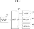
- Fig. 4 is a functional block diagram of the input device 110.
- the direction of the rotational axis AX which is the rotation center of the rotating body 130, is referred to as an up-down direction, and a direction orthogonal to the rotational axis AX is referred to as a radial direction.
- the up-down direction may be set to any direction depending on, for example, the orientation of the input device.
- a view in the direction of the rotational axis AX is referred to as a plan view, and a direction of a circumference of a circle centered on the rotational axis AX in a plan view is referred to as a circumferential direction.
- the input device 110 includes a fixed portion 120, the rotating body 130, a connecting member 135, a rotation detection unit 140, a torque applying unit 150, and a brake applying unit 210, and is used in an assembled state illustrated in Figs. 1(a) and 1(b) .
- the input device 110 further includes a controller 160 illustrated in Fig. 4 .
- the fixed portion 120 is a plate member composed of a non-magnetic body.
- the fixed portion 120 has an opening 121 that extends therethrough in the up-down direction in a central region thereof in plan view.
- a shaft portion 311 of the brake applying unit 210 extends to the outside through the opening 121 (see Fig. 1(b) ).
- the torque applying unit 150 includes a base plate 151, a fixed member 152, a coil unit 153, a magnet unit 154, a back yoke 155, and a coil holder 156, and is substantially symmetrical about the rotational axis AX.
- the fixed member 152 which is made of a non-magnetic material
- the coil unit 153 which is fixed to the inner peripheral surface of the fixed member 152, form a stator.
- the magnet unit 154 which is disposed to face the inner peripheral surface of the coil unit 153
- the back yoke 155 which is fixed to the inner peripheral surface of the magnet unit 154, form a rotor.
- the rotor is supported such that the rotor is rotatable with respect to the stator.
- the base plate 151 is substantially circular plate-shaped, and is fixed to the fixed portion 120 so that the central axis thereof coincides with the rotational axis AX.
- a cylindrical pretensioner 151a is disposed concentrically to the base plate 151 at the center of the base plate 151.
- the pretensioner 151a is fixed such that the pretensioner 151a extends through the fixed portion 120 and the base plate 151 in the up-down direction.
- the pretensioner 151a radially supports a shaft 310 that extends therethrough.
- the base plate 151 has positioning recesses 151b arranged along the outer periphery thereof.
- the positioning recesses 151b serve as coil holders for positioning and holding lower portions of air-core coils 153a to 153h (described below).
- the base plate 151 also has an outer edge recess 151c disposed outside the positioning recesses 151b and recessed further downward from the positioning recesses 151b.
- the base plate 151 is substantially symmetrical about the rotational axis AX.
- lower portions of the coil unit 153 are inserted into the positioning recesses 151b, so that the coil unit 153 is positioned.
- a plurality of conductive pins 122 are provided to extend through the base plate 151 in the up-down direction.
- the pins 122 are exposed to the outside through the opening 121 in the fixed portion 120 at the bottom of the input device 110.
- the controller 160 supplies predetermined currents to the coil unit 153, a first coil 250 of the brake applying unit 210, and a second coil 450 of the brake applying unit 210 through the pins 122.
- a lower portion of the fixed member 152 which has a cylindrical shape, is fitted to the outer edge recess 151c of the base plate 151, so that the fixed member 152 is positioned along the outer periphery of the base plate 151 and fixed to the base plate 151 and the fixed portion 120.
- the fixed member 152 is substantially symmetrical about the rotational axis AX.
- eight air-core coils 153a, 153b, 153c, 153d, 153e, 153f, 153g, and 153h which serve as torque applying coils, are provided on the inner peripheral surface of the fixed member 152.
- the eight air-core coils 153a to 153h form the coil unit 153.
- the above-described eight air-core coils 153a, 153b, 153c, 153d, 153e, 153f, 153g, and 153h are provided on an inner peripheral surface 152a (see Fig. 2 ) of the fixed member 152 and arranged in the circumferential direction thereof.
- the eight air-core coils 153a to 153h are arranged at constant angular intervals along a circle centered on the rotational axis AX, and are each wound around a center line extending radially from the rotational axis AX toward the circumference of the circle.
- the coil unit 153 is substantially symmetrical about the rotational axis AX.
- the air-core coils 153a to 153h each receive a current controlled by the controller 160 (see Fig. 4 ).
- the magnet unit 154 includes six magnets 154a, 154b, 154c, 154d, 154e, and 154f. These magnets 154a to 154f are disposed inside the air-core coils 153a to 153h of the coil unit 153 to face the air-core coils 153a to 153h such that the magnets 154a to 154f are radially spaced from the air-core coils 153a to 153h by a predetermined distance. In addition, as illustrated in Figs.
- the magnets 154a to 154f are provided on an outer peripheral surface 155a of the back yoke 155, which has a cylindrical shape, and arranged in the circumferential direction thereof.
- the magnets 154a to 154f are arranged at constant angular intervals along a circle centered on the rotational axis AX, and each have magnetic poles arranged radially in a direction from the rotational axis AX toward the circumference of the circle.
- the magnetic poles are arranged such that opposite magnetic poles are disposed adjacent to each other.
- the magnet unit 154 and the back yoke 155 are each substantially symmetrical about the rotational axis AX.
- the magnet 154a has an S pole at the outer end and an N pole at the inner end adjacent to the rotational axis AX.
- Figs. 5(a) to 5(d) are plan views illustrating the relationships between the air-core coils 153a to 153h of the coil unit 153 and the magnets 154a to 154f of the magnet unit 154.
- Figs. 5(a) to 5(d) illustrate states in which the magnets 154a to 154f are in stable positions, that is, positions where the maximum torque is generated, when the air-core coils 153a to 153h are in different energization states.
- Figs. 5(a) to 5(d) are plan views illustrating the relationships between the air-core coils 153a to 153h of the coil unit 153 and the magnets 154a to 154f of the magnet unit 154.
- Figs. 5(a) to 5(d) illustrate states in which the magnets 154a to 154f are in stable positions, that is, positions where the maximum torque is generated, when the air-core coils 153a to 153h are in different energization
- 5(a) to 5(d) show the directions in which currents applied to the air-core coils 153a to 153h flow along the up-down direction (direction of the rotational axis AX): " ⁇ ” shows the front-to-back direction in each figure, and “•” (black circle) shows the back-to-front direction in each figure.
- the eight air-core coils 153a to 153h are positioned in the up-down direction and held by the coil holder 156 and the base plate 151.
- the coil holder 156 is ring-shaped, and is fixed to the outer peripheral surface of the fixed member 152 at the top end thereof so that the central axis of the coil holder 156 coincides with the rotational axis AX.
- the coil holder 156 is substantially symmetrical about the rotational axis AX.
- the base plate 151, the fixed member 152, the coil unit 153, the magnet unit 154, the back yoke 155, and the coil holder 156 are each substantially symmetrical about the rotational axis AX. Therefore, the overall structure of the torque applying unit 150 is substantially symmetrical about the rotational axis AX.
- currents are applied to the air-core coils 153a to 153h in groups of four, more specifically, to two adjacent air-core coils and other two adjacent air-coils that are symmetric to the first two adjacent air-core coils about the rotational axis AX.
- phase A the state in which currents are applied to a group of coils including two adjacent air-core coils 153b and 153c and other two air-core coils 153f and 153g that are symmetric to the air-core coils 153b and 153c about the rotational axis AX is defined as phase A.
- phase B the state in which currents are applied to the other group of coils that receive no currents in phase A, that is, two adjacent air-core coils 153h and 153a and other two air-core coils 153d and 153e that are symmetric to the air-core coils 153h and 153a about the rotational axis AX, is defined as phase B.
- the four coils that form each group are connected in series. More specifically, the four air-core coils 153b, 153c, 153f, and 153g that correspond to phase A are connected in series, and the four air-core coils 153h, 153a, 153d, and 153e that correspond to phase B are connected in series.
- Energization of the air-core coils 153a to 153h is controlled so that switching between the above-described two phases, that is, phase A and phase B, occurs every time the rotating body 130 rotates 120 degrees. Accordingly, switching between the states illustrated in Figs. 5(a) to 5(d) occurs three times during one revolution of the rotating body 130 at intervals of 120 degrees.
- the two adjacent air-core coils 153b and 153c receive currents in the opposite directions.
- the air-core coil 153f which is symmetric to the air-core coil 153b about the rotational axis AX, receives a current in a direction opposite to that of the current applied to the air-core coil 153b
- the air-core coil 153g which is symmetric to the air-core coil 153c, receives a current in a direction opposite to that of the current applied to the air-core coil 153c.
- the adjacent coils generate magnetic fields in the opposite directions
- two coils that are symmetric to each other about the rotational axis AX generate magnetic fields in the same direction.
- the magnet unit 154 can be rotated or turned about the rotational axis AX with respect to the coil unit 153, which is fixed to the base plate 151, the fixed member 152, and the fixed portion 120, by applying currents to the air-core coils 153a to 153h in four patterns illustrated in Figs. 5(a) to 5(d) . Accordingly, the back yoke 155, to which the magnet unit 154 is fixed, is also rotated or turned.
- the rotating body 130 which will be described below, is concentrically fixed to the back yoke 155, and rotating or turning driving torque is transmitted to the rotating body 130 when the magnet unit 154 is rotated or turned.
- Fig. 6(a) is a perspective view of the brake applying unit 210 viewed from above
- Fig. 6(b) is a perspective view of the brake applying unit 210 viewed from below
- Figs. 7 and Fig. 8 are exploded perspective views of the brake applying unit 210 viewed from above.
- Fig. 7 is a perspective view of an upper section 210A that is above position A
- Fig. 8 is a perspective view of a lower section 210B that is blow position A.
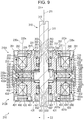
- Fig. 9 is a sectional view of Fig. 6(a) taken along line IX-IX', and conceptually illustrates magnetic fields generated by the two coils 250 and 450.
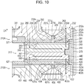
- Fig. 10 is an enlarged view of part of Fig. 9 .
- a central axis 211 is referred to as a first direction D1 ( Figs. 6 and 9 ), and a radial direction orthogonal to the central axis 211 is referred to as a second direction D2 ( Figs. 6 and 9 ).
- a view from above in the direction of the central axis 211 may be referred to as a plan view.
- some screws and magnetic viscous fluid are omitted.
- the brake applying unit 210 includes a holder unit 220 and a rotation operation unit 300, and is substantially symmetrical about the central axis 211.
- the rotation operation unit 300 includes the shaft 310 and two magnetic discs 320 and 520 (rotary plates), which are connected together to be capable of rotating together in both directions about the central axis 211 (rotational axis).
- the brake applying unit 210 is disposed in the back yoke 155 such that the outer peripheral surfaces of an outer yoke 232, an annular member 270, and an outer yoke 432, which will be described below, face the inner peripheral surface of the back yoke 155 and are spaced from the inner peripheral surface of the back yoke 155.
- the torque applying unit 150 is disposed to surround the outer periphery of the brake applying unit 210.
- the brake applying unit 210 is disposed such that the central axis 211 thereof coincides with the rotational axis AX of the rotating body 130, and the bottom surface of a third yoke 490 of the brake applying unit 210 is fixed to the base plate 151.
- the first direction D1 is the direction of the rotational axis AX
- the second direction D2 is orthogonal to the direction of the rotational axis AX.
- the rotation operation unit 300 is rotatably supported on the holder unit 220 by two radial bearings 351 and 551 and two pushers 352 and 552 (see Figs. 7 and 8 ). As illustrated in Fig. 10 , two gaps 280 and 480 formed in the brake applying unit 210 are filled with magnetic viscous fluids 360 and 560, respectively.
- the holder unit 220 includes a first yoke 230, a second yoke 240, the first coil 250, which serves as a brake applying coil, a sealing member 260, and a third yoke 290, which serves as an upper casing.
- the first yoke 230 is disposed on one side of the magnetic disc 320 and the second yoke 240 is disposed on the other side of the magnetic disc 320 in the first direction D1.
- the first yoke 230, the second yoke 240, the first coil 250, the sealing member 260, and the third yoke 290 are each substantially symmetrical about the central axis 211 (rotational axis). Therefore, the overall structure in the upper section 210A of the holder unit 220 is substantially symmetrical about the central axis 211 (rotational axis).
- the holder unit 220 includes a first yoke 430, a second yoke 440, the second coil 450, which serves as a brake applying coil, a sealing member 460, and the third yoke 490, which serves as a lower casing.
- the first yoke 430 is disposed on one side of the magnetic disc 520 and the second yoke 440 is disposed on the other side of the magnetic disc 520 in the first direction D1.
- the first yoke 430, the second yoke 440, the second coil 450, the sealing member 460, and the third yoke 490 are each substantially symmetrical about the central axis 211 (rotational axis). Therefore, the overall structure of the lower section 210B of the holder unit 220 is substantially symmetrical about the central axis 211 (rotational axis).
- the holder unit 220 includes the annular member 270 that extends in both the upper section 210A and the lower section 210B.
- the first yoke 230, the second yoke 240, and the third yoke 290 are formed separately.
- the first yoke 430, the second yoke 440, and the third yoke 490 are formed separately.
- some of these yokes may instead be formed integrally with each other.
- the first coil 250 in the upper section 210A has an annular shape.
- the first coil 250 is a coil including a conductive wire wound around the central axis 211.
- the second coil 450 in the lower section 210B also has an annular shape.
- the second coil 450 is also a coil including a conductive wire wound around the central axis 211.
- the first coil 250 and the second coil 450 are each substantially symmetrical about the central axis 211 (rotational axis).
- the two coils 250 and 450 are electrically connected to connecting members (not shown), and currents are supplied thereto from the controller 160 along paths that are not illustrated.
- the coils 250 and 450 each generate a magnetic field when currents are supplied thereto.
- the first yoke 230 in the upper section 210A includes an inner yoke 231 as an inner peripheral member and the outer yoke 232 as an outer peripheral member.
- the inner yoke 231 and the outer yoke 232 are concentrically arranged about the central axis 211.
- the first yoke 430 in the lower section 210B includes an inner yoke 431 as an inner peripheral member and the outer yoke 432 as an outer peripheral member.
- the inner yoke 431 and the outer yoke 432 are concentrically arranged about the central axis 211.
- the two first yokes 230 and 430 are each substantially symmetrical about the central axis 211 (rotational axis).
- the inner yoke 231 in the upper section 210A includes a cylindrical portion 231a and a flange-shaped portion 231b ( Fig. 10 ) having an annular shape in plan view and extending radially outward from a lower surface of the cylindrical portion 231a.
- the outer diameter of the outer peripheral surface of an upper portion of the cylindrical portion 231a and the inner diameter of the inner peripheral surface of the cylindrical portion 231a vary depending on the positions in the up-down direction.
- the inner yoke 431 in the lower section 210B includes a cylindrical portion 431a and a flange-shaped portion 431b ( Fig.
- the outer diameter of the outer peripheral surface of a lower portion of the cylindrical portion 431a and the inner diameter of the inner peripheral surface of the cylindrical portion 431a vary depending on the positions in the up-down direction.
- the outer yoke 232 in the upper section 210A includes a cylindrical portion 232a and an edge portion 232b having an annular shape in plan view and extending radially inward from a lower surface of the cylindrical portion 232a.
- the inner peripheral surface of the cylindrical portion 232a of the outer yoke 232 faces the outer peripheral surface of the cylindrical portion 231a of the inner yoke 231 so that a first space 233 having an annular shape is formed therebetween.
- the first coil 250 which serves as a brake applying coil, is disposed in the first space 233.
- the third yoke 290 which is substantially circular plate-shaped, is placed on the inner yoke 231 from above, and is fixed to the inner yoke 231 and the outer yoke 232 with screws 291 so that the first space 233 is closed and that the inner yoke 231, the outer yoke 232, and the third yoke 290 form a magnetic path that surrounds the first coil 250.
- the third yoke 290 is disposed such that the center thereof is on the central axis 211, and is therefore substantially symmetrical about the central axis 211 (rotational axis).
- the outer yoke 432 in the lower section 210B includes a cylindrical portion 432a and an edge portion 432b having an annular shape in plan view and extending radially inward from an upper surface of the cylindrical portion 432a.
- the inner peripheral surface of the cylindrical portion 432a of the outer yoke 432 faces the outer peripheral surface of the cylindrical portion 431a of the inner yoke 431 so that a first space 433 having an annular shape is formed therebetween.
- the second coil 450 which serves as a brake applying coil, is disposed in the first space 433.
- the third yoke 490 which is substantially circular plate-shaped, is disposed below the inner yoke 431 and fixed to the inner yoke 431 and the outer yoke 432 with screws 491 so that the first space 433 is closed and that the inner yoke 431, the outer yoke 432, and the third yoke 490 form a magnetic path that surrounds the second coil 450.
- the third yoke 490 is disposed such that the center thereof is on the central axis 211, and is therefore substantially symmetrical about the central axis 211 (rotational axis).
- annular spaces 234 and 235 are also formed between the inner peripheral surface of the edge portion 232b of the outer yoke 232 and the outer peripheral surface of the flange-shaped portion 231b of the inner yoke 231.
- the second space 234 is connected to the above-described first space 233, and the third space 235 is connected to the second space 234.
- the inner peripheral surface of the flange-shaped portion 231b includes a first surface 231c that is inclined outward in the radial direction (direction D2 in Fig. 9 ) and downward and a second surface 231d that extends in the first direction (direction D1 in Fig. 10 ) from the bottom end of the first surface 231c.
- the inner peripheral surface of the edge portion 232b includes a first surface 232c that is inclined inward in the radial direction and downward and a second surface 232d that extends in the first direction D1 from the bottom end of the first surface 232c.
- the first surface 231c of the inner yoke 231 and the first surface 232c of the outer yoke 232 are disposed at positions corresponding to each other in the first direction D1 so as to form the second space 234 therebetween.
- the second space 234 is a space in which no object is disposed, and forms a magnetic gap whose width in the radial direction decreases toward the bottom.
- the magnetic gap is shaped such that the width thereof in the radial direction increases toward the first coil 250, that is, toward the top.
- the second surface 231d and the second surface 232d are arranged to extend parallel to each other and face each other in the radial direction at positions corresponding to each other in the first direction D1, thereby forming the third space 235 therebetween.
- the sealing member 260 which is composed of a non-magnetic body, is disposed in the third space 235, so that the second space 234 and the third space 235 form a magnetic gap.
- the sealing member 260 has an annular shape and is made of a non-magnetic material, such as a synthetic resin.
- the sealing member 260 is formed by, for example, filling the third space 235 with a material in a fluid state and solidifying the material.
- an elastic material formed in an annular shape may be fitted into the third space 235.
- a non-elastic material may be formed into an annular shape and fixed with an adhesive.
- the sealing member 260 disposed in the third space 235 is substantially symmetrical about the central axis 211 (rotational axis).
- a lower surface 231e of the inner yoke 231 and a lower surface 232e of the outer yoke 232 form a facing surface that faces the magnetic disc 320 ( Figs. 9 and 10 ).
- the facing surface is divided into inner and outer regions by the magnetic gap formed by the second space 234 and the third space 235.
- the inner region corresponds to the lower surface 231e of the inner yoke 231, and the outer region corresponds to the lower surface 232e of the outer yoke 232.
- the magnetic gap is provided at a position such that the inner region of the facing surface that is inside the magnetic gap and the outer region of the facing surface that is outside the magnetic gap have substantially the same area.
- the inner yoke 231 and the outer yoke 232 have substantially the same cross-sectional area along a plane orthogonal to the central axis 211 at the position where the first coil 250 is disposed. Accordingly, a magnetic field having an optimum structure can be realized until the saturation magnetic flux density is reached.
- annular spaces 434 and 435 are also formed between the inner peripheral surface of the edge portion 432b of the outer yoke 432 and the outer peripheral surface of the flange-shaped portion 431b of the inner yoke 431.
- the second space 434 is connected to the above-described first space 433, and the third space 435 is connected to the second space 434.
- the inner peripheral surface of the flange-shaped portion 431b includes a first surface 431c that is inclined outward in the radial direction and upward and a second surface 431d that extends in the first direction D1 from the top end of the first surface 431c.
- the inner peripheral surface of the edge portion 432b includes a first surface 432c that is inclined inward in the radial direction and upward and a second surface 432d that extends in the first direction D1 from the top end of the first surface 432c.
- the first surface 431c of the inner yoke 431 and the first surface 432c of the outer yoke 432 are disposed at positions corresponding to each other in the first direction D1 so as to form the second space 434 therebetween.
- the second space 434 is a space in which no object is disposed, and forms a magnetic gap whose width in the radial direction decreases toward the top.
- the magnetic gap is shaped such that the width thereof in the radial direction increases toward the second coil 450, that is, toward the bottom.
- the second surface 431d and the second surface 432d are arranged to extend parallel to each other and face each other in the radial direction at positions corresponding to each other in the first direction D1, thereby forming the third space 435 therebetween.
- the sealing member 460 which is composed of a non-magnetic body, is disposed in the third space 435, so that the second space 434 and the third space 435 form a magnetic gap.
- the sealing member 460 and the above-described sealing member 260 have the same structure and are made of the same material.
- the sealing member 460 disposed in the third space 435 is substantially symmetrical about the central axis 211 (rotational axis).
- An upper surface 431e of the inner yoke 431 and an upper surface 432e of the outer yoke 432 form a facing surface that faces the magnetic disc 520 ( Figs. 9 and 10 ).
- the facing surface is divided into inner and outer regions by the magnetic gap formed by the second space 434 and the third space 435.
- the inner region corresponds to the upper surface 431e of the inner yoke 431, and the outer region corresponds to the upper surface 432e of the outer yoke 432.
- the magnetic gap is provided at a position such that the inner region of the facing surface that is inside the magnetic gap and the outer region of the facing surface that is outside the magnetic gap have substantially the same area.
- the inner yoke 431 and the outer yoke 432 have substantially the same cross-sectional area along a plane orthogonal to the central axis 211 at the position where the second coil 450 is disposed. Accordingly, a magnetic field having an optimum structure can be realized until the saturation magnetic flux density is reached.
- the width of the first space 233 is set to be greater than the width of the second space 234 in the radial direction (second direction D2).
- a center position 235x of the third space 235 in the radial direction is located outside a center position 233x of the first space 233 in the radial direction.
- the width of the first space 433 is set to be greater than the width of the second space 434.
- center position of the third space 435 in the radial direction coincides with the above-described center position 235x, and is located outside the above-described center position 233x, which coincides with the center position of the first space 433 in the radial direction.
- the first surface 231c of the inner yoke 231 and the first surface 232c of the outer yoke 232 have different inclination angles with respect to the first direction D1, and the first surface 231c of the inner yoke 231 has a greater inclination angle.
- the first surface 231c of the inner yoke 231 has a smaller inclination angle with respect to the radial direction.
- the first surface 431c of the inner yoke 431 and the first surface 432c of the outer yoke 432 have different inclination angles with respect to the first direction D1, and the first surface 431c of the inner yoke 431 has a greater inclination angle. In other words, the first surface 431c of the inner yoke 431 has a smaller inclination angle with respect to the radial direction.
- the inner yoke 231 and the outer yoke 232 in the upper section 210A are shaped such that the center position 235x of the third space 235 in the radial direction is located outside the center of the overall body of the first yoke 230 in the radial direction.
- the lower surface 231e serving as a facing surface of the inner yoke 231 that faces the magnetic disc 320 and the lower surface 232e serving as a facing surface of the outer yoke 232 that faces the magnetic disc 320 have substantially the same area in plan view.
- the magnetic flux density in the region inside the magnetic gap and that in the region outside the magnetic gap are substantially equal to each other.
- the inner yoke 431 and the outer yoke 432 in the lower section 210B are also shaped such that the above-described center position 235x, which coincides with the center position of the third space 435 in the radial direction, is located outside the center of the overall body of the first yoke 430 in the radial direction. Accordingly, the upper surface 431e serving as a facing surface of the inner yoke 431 that faces the magnetic disc 520 and the upper surface 432e serving as a facing surface of the outer yoke 432 that faces the magnetic disc 520 have substantially the same area in plan view. Thus, the magnetic flux density in the region inside the magnetic gap and that in the region outside the magnetic gap are substantially equal to each other.
- the second yoke 240 in the upper section 210A has the shape of a circular plate, and is disposed below the first yoke 230 so that the center of the circular plate is on the central axis 211.
- the second yoke 240 has a top surface 241 that is orthogonal to the up-down direction, which is the direction of the central axis 211.
- the second yoke 240 has an annular hole 242 that surrounds the central axis 211 and extends through the second yoke 240 in the up-down direction. As illustrated in Fig.
- the second yoke 440 in the lower section 210B has the shape of a circular plate, and is disposed above the first yoke 430 so that the center of the circular plate is on the central axis 211.
- the second yoke 440 has a bottom surface 441 that is orthogonal to the up-down direction, which is the direction of the central axis 211.
- the second yoke 440 has an annular hole 442 that surrounds the central axis 211 and extends through the second yoke 440 in the up-down direction.
- the two second yokes 240 and 440 are substantially symmetrical about the central axis 211 (rotational axis).
- the second yoke 240 and the second yoke 440 are stacked in the first direction D1 such that the second yoke 240 is disposed above the second yoke 440, and the shaft portion 311 of the shaft 310 is inserted through the hole 242 in the second yoke 240 and the hole 442 in the second yoke 440.
- the shaft portion 311 is disposed to extend in the first direction D1, and has a flange portion 312 at substantially the center thereof in the extending direction.
- the flange portion 312 is flange-shaped and extends outward from the outer peripheral surface of the shaft portion 311.
- the thickness of the flange portion 312 in the first direction D1 is greater than the total thickness of the second yoke 240 and the second yoke 440 by a predetermined amount.
- the predetermined amount corresponds to the dimensions of the gaps between the second yoke 240 and the magnetic disc 320 and between the second yoke 440 and the magnetic disc 520.
- the shapes of the yokes 230, 240, 290, 430, 440, and 490 in plan view are not limited to circular shapes.
- a bottom surface 236 of the first yoke 230 and a lower surface 261 of the sealing member 260 are substantially parallel to the top surface 241 of the second yoke 240, and the magnetic disc 320 is disposed between the bottom surface 236 and the top surface 241.
- the gap 280 is formed between the magnetic disc 320 and the bottom surface 236 and between the magnetic disc 320 and the top surface 241.
- a top surface 436 of the first yoke 430 and an upper surface 461 of the sealing member 460 are substantially parallel to the bottom surface 441 of the second yoke 440, and the magnetic disc 520 is disposed between the top surface 436 and the bottom surface 441.
- the gap 480 is formed between the magnetic disc 520 and the top surface 436 and between the magnetic disc 520 and the bottom surface 441.
- the annular member 270 is disposed outside the first yoke 230 and the second yoke 240 in the radial direction in the upper section 210A, and outside the first yoke 430 and the second yoke 440 in the radial direction in the lower section 210B.
- the annular member 270 has an annular shape having an axis that coincides with the central axis 211, and is made of a non-magnetic material, such as a synthetic resin.
- the inner peripheral surface of the annular member 270 is shaped to extend along the first yoke 230 and the second yoke 240 in the upper section 210A and along the first yoke 430 and the second yoke 440 in the lower section 210B, and is fixed to the outer peripheral surface of each yoke. Accordingly, the first yoke 230 in the upper section 210A, the second yoke 240 in the upper section 210A, the second yoke 440 in the lower section 210B, and the first yoke 430 in the lower section 210B are arranged in that order in the first direction D1 and connected to each other by the annular member 270 that extends in the first direction D1.
- the gap 280 in the upper section 210A and the gap 480 in the lower section 210B are each closed by the annular member 270 in the radial direction.
- first yoke 230 and the second yoke 240 in the upper section 210A and the second yoke 440 and the first yoke 430 in the lower section 210B are arranged in that order and connected to each other by the annular member 270, and thus the holder unit 220 is integrally fixed.
- the entire body of the annular member 270 be made of a non-magnetic material, and the annular member 270 may instead be made of a composite material including a non-magnetic portion that prevents magnetic short-circuiting between the first yoke 230 and the second yoke 240 in the upper section 210A and between the first yoke 430 and the second yoke 440 in the lower section 210B.
- the gap 480 is preferably closed by the non-magnetic portion in the radial direction.
- the magnetic disc 320 extends in the direction orthogonal to the central axis 211 in the gap 280 between the first yoke 230 and the second yoke 240.
- the magnetic disc 320 is positioned to overlap the first coil 250 in the direction of the central axis 211.
- the magnetic disc 520 extends in the direction orthogonal to the central axis 211 in the gap 480 between the first yoke 430 and the second yoke 440.
- the magnetic disc 520 is positioned to overlap the second coil 450 in the direction of the central axis 211.
- the annular member 270 surrounds the outer peripheral surface of the magnetic disc 320 over the entire circumference with a gap 281 therebetween, and also surrounds the outer peripheral surface of the magnetic disc 520 over the entire circumference with a gap 481 therebetween.
- the inner yoke 231 and the outer yoke 232 of the first yoke 230 and the third yoke 290 are connected together, and the second yoke 240 is connected thereto with the magnetic disc 320 provided therebetween as described above, so that a closed-loop magnetic path (magnetic circuit) for a magnetic field generated by the first coil 250 is formed.
- the inner yoke 431 and the outer yoke 432 of the first yoke 430 and the third yoke 490 are connected together, and the second yoke 440 is connected thereto with the magnetic disc 520 provided therebetween as described above, so that a closed-loop magnetic path (magnetic circuit) for a magnetic field generated by the second coil 450 is formed.
- magnetic flux extends from the inner yoke 231 of the first yoke 230 toward the second yoke 240 in the direction of the central axis 211, passes through the magnetic disc 320 disposed in the gap 280, and extends through the second yoke 240 in the direction away from the central axis 211. Then, in a radially outer region of the second yoke 240, the magnetic flux extends upward in the direction of the central axis 211, that is, from the second yoke 240 toward the outer yoke 232.
- the magnetic flux extends through the third yoke 290 disposed above the first coil 250 in the direction from the outer yoke 232 to the inner yoke 231, that is, in the direction toward the central axis 211, and then extends downward through the inner yoke 231 of the first yoke 230 in a region inside the first coil 250. Then, the magnetic flux passes through the magnetic disc 320 again and reaches the second yoke 240.
- magnetic flux extends from the inner yoke 431 of the first yoke 430 toward the second yoke 440 in the direction of the central axis 211, passes through the magnetic disc 520 disposed in the gap 480, and extends through the second yoke 440 in the direction away from the central axis 211. Then, in a radially outer region of the second yoke 440, the magnetic flux extends downward in the direction of the central axis 211, that is, from the second yoke 440 toward the outer yoke 432.
- the magnetic flux extends through the third yoke 490 disposed below the second coil 450 in the direction from the outer yoke 432 to the inner yoke 431, that is, in the direction toward the central axis 211, and then extends upward through the inner yoke 431 of the first yoke 430 in a region inside the second coil 450. Then, the magnetic flux extends through the magnetic disc 520 again and reaches the second yoke 440.
- the first yoke 230 in the upper section 210A has the second space 234 and the third space 235 that form a magnetic gap in the magnetic field having the above-described magnetic path.
- This magnetic gap is provided below the first coil 250 and between the first coil 250 and the gap 280 in which the magnetic disc 320 is disposed.
- the first coil 250 is spaced from the magnetic disc 320 and disposed in the first yoke 230, and the magnetic gap is formed in a portion of the space between the first coil 250 and the magnetic disc 320. Therefore, in the region around the magnetic gap, the magnetic flux of the magnetic field generated by the first coil 250 is restrained from extending through the first yoke 230 in the radial direction orthogonal to the central axis 211.
- the magnetic flux of the magnetic field generated by the first coil 250 can be directed toward the magnetic disc 320 along two inclined surfaces, which are the first surface 231c of the inner yoke 231 and the first surface 232c of the outer yoke 232. Accordingly, the magnetic flux that passes through the inner yoke 231 reliably extends downward toward the second yoke 240, and the magnetic flux that passes through the outer yoke 232 reliably extends upward in the direction from the second yoke 240 toward the third yoke 290.
- the first yoke 430 in the lower section 210B also has the second space 434 and the third space 435 that form a magnetic gap.
- This magnetic gap is provided above the second coil 450 and between the second coil 450 and the gap 480 in which the magnetic disc 520 is disposed.
- the second coil 450 is spaced from the magnetic disc 520 and disposed in the first yoke 430, and the magnetic gap is formed in a portion of the space between the second coil 450 and the magnetic disc 520. Therefore, in the region around the magnetic gap, the magnetic flux of the magnetic field generated by the second coil 450 is restrained from extending through the first yoke 430 in the radial direction orthogonal to the central axis 211.
- the magnetic flux of the magnetic field generated by the second coil 450 can be directed toward the magnetic disc 520 along two inclined surfaces, which are the first surface 431c of the inner yoke 431 and the first surface 432c of the outer yoke 432. Accordingly, the magnetic flux that passes through the inner yoke 431 reliably extends upward toward the second yoke 440, and the magnetic flux that passes through the outer yoke 432 reliably extends downward in the direction from the second yoke 440 toward the third yoke 490.
- the magnetic fields generated in the upper section 210A and the lower section 210B of the brake applying unit 210 are generated by the coils 250 and 450 wound around the central axis 211 that coincides with the rotational axis AX.
- the magnetic fields generated in the torque applying unit 150 are generated by the air-core coils 153a to 153h wound around radial lines that are orthogonal to the rotational axis AX.
- the center line of the two coils 250 and 450 of the brake applying unit 210 is orthogonal to the center lines of the air-core coils 153a to 153h of the torque applying unit 150, so that interference between the magnetic fields generated in the brake applying unit 210 and the magnetic fields generated in the torque applying unit 150 can be reduced.
- the shaft 310 is a rod-shaped component that extends along the central axis 211 in the up-down direction, and includes the flange portion 312 provided substantially at the center thereof in the first direction D1 and the shaft portion 311 that extends from the flange portion 312 in the up-down direction.
- the rotation operation unit 300 is substantially symmetrical about the central axis 211 (rotational axis).
- the upper section 210A and the lower section 210B of the holder unit 220 are each substantially symmetrical about the central axis 211 (rotational axis). Therefore, the overall body of the brake applying unit is substantially symmetrical about the central axis 211 (rotational axis).
- the magnetic disc 320 in the upper section 210A and the magnetic disc 520 in the lower section 210B have the shape of a circular plate with a circular flat surface orthogonal to the first direction D1, and are made of a magnetic material.
- the magnetic discs 320 and 520 have the same shape.
- the magnetic disc 320 in the upper section 210A has a center hole 321 that extends therethrough in the first direction D1 at the center of the circular flat surface.
- the magnetic disc 320 also has a plurality of through holes 322 that extend therethrough in the up-down direction at positions around the center hole 321.
- the magnetic disc 320 is fixed to the shaft 310 by inserting screws (only one of which is illustrated) through the through holes 322 in the first direction D1 and fitting shaft portions of the screws to the flange portion 312 of the shaft 310.
- the magnetic disc 520 in the lower section 210B has a center hole 521 that extends therethrough in the first direction D1 at the center of the circular flat surface.
- the magnetic disc 520 also has a plurality of through holes 522 that extend therethrough in the up-down direction at positions around the center hole 521.
- the magnetic disc 520 is fixed to the shaft 310 by inserting screws (only one of which is illustrated) through the through holes 522 in the first direction D1 and fitting shaft portions of the screws to the flange portion 312 of the shaft 310.
- the inner diameter of the center hole 321 in the magnetic disc 320 in the upper section 210A and the inner diameter of the center hole 521 in the magnetic disc 520 in the lower section 210B are each substantially equal to the outer diameter of the shaft portion 311 of the shaft 310 and less than the outer diameter of the flange portion 312.
- the thickness of the flange portion 312 in the first direction D1 is greater than the total thickness of the second yoke 240 and the second yoke 440 by a predetermined amount.
- the flange portion 312 projects upward from the top surface 241 of the second yoke 240 so as to be in contact with the lower surface of the magnetic disc 320, and projects downward from the bottom surface 441 of the second yoke 440 so as to be in contact with the upper surface of the magnetic disc 520.
- the height of a portion of the gap 280 between the magnetic disc 320 and the second yoke 240 is determined by the amount by which the flange portion 312 projects from the second yoke 240, and the height of a portion of the gap 480 between the magnetic disc 520 and the second yoke 440 is determined by the amount by which the flange portion 312 projects from the second yoke 440.
- the shaft portion 311 of the shaft 310 is rotatably supported by the radial bearing 351 in the upper section 210A, and the radial bearing 351 is supported and urged upward in the first direction D1 (upward in Fig. 9 ) by the pusher 352.
- the pusher 352 is supported by an O-ring 353 disposed between the outer peripheral surface of the shaft portion 311 and the inner peripheral surface of the inner yoke 231 such that the position thereof in the up-down direction is maintained.
- the radial bearing 351 is supported at a predetermined position in the first direction D1 while being continuously in tight contact with the first yoke 230.
- An upper portion of the shaft portion 311 projects upward from the third yoke 290 and is exposed.
- the exposed portion of the shaft portion 311 has a joining recess 313 to which a joining projection 134a of the connecting shaft portion 134 is fitted.
- the shaft portion 311 of the shaft 310 is rotatably supported by the radial bearing 551 in the lower section 210B, and the radial bearing 551 is supported and urged downward in the first direction D1 by the pusher 552.
- the pusher 552 is supported by an O-ring 553 disposed between the outer peripheral surface of the shaft portion 311 and the inner peripheral surface of the inner yoke 431 such that the position thereof in the up-down direction is maintained.
- the radial bearing 551 is supported at a predetermined position in the first direction D1 while being continuously in tight contact with the first yoke 430.
- a lower portion of the shaft portion 311 projects downward from the third yoke 490 by a predetermined amount and is exposed. The amount by which the lower portion of the shaft portion 311 projects is set such that the shaft portion 311 can be reliably supported by the radial bearing 551.
- the magnetic disc 320 in the upper section 210A has four slits 323a, 323b, 323c, and 323d that extend therethrough in the first direction D1 (thickness direction). These slits are provided at the same distance from the center of the circular flat surface and extend in the circumferential direction at constant angular intervals. In addition, the slits are provided at a position corresponding to the position of the third space 235 in the radial direction.
- the four slits 323a, 323b, 323c, and 323d serve as magnetic gaps so that the magnetic flux of the magnetic field is restrained from passing through the four slits 323a, 323b, 323c, and 323d in the radial direction.
- the magnetic flux extends downward from the inner yoke 231 of the first yoke 230 toward the second yoke 240 in a region closer to the central axis 211 than the four slits 323a, 323b, 323c, and 323d (inner region). In the region outside the four slits 323a, 323b, 323c, and 323d, the magnetic flux extends upward from the second yoke 240 toward the outer yoke 232 of the first yoke 230. The magnetic flux is restrained from passing through the four slits in the magnetic disc 320 in the radial direction.
- the four slits are provided at a position corresponding to the position of the third space 235, the second space 234, the third space 235, and the four slits 323a, 323b, 323c, and 323d are arranged in the first direction D1. Therefore, the magnetic field generated by the first coil 250 is reliably restrained from extending through the first yoke 230 or the magnetic disc 320 in the radial direction, and a stable magnetic circuit can be obtained.
- the magnetic disc 520 in the lower section 210B also has four slits 523a, 523b, 523c, and 523d that extend therethrough in the first direction D1 (thickness direction). These slits are provided at the same distance from the center of the circular flat surface and extend in the circumferential direction at constant angular intervals. In addition, the slits are provided at a position corresponding to the position of the third space 435 in the radial direction. The magnetic flux is restrained from passing through the four slits in the magnetic disc 520 in the radial direction.
- the second coil 450 When the second coil 450 generates the magnetic field illustrated in Fig.
- the four slits 523a, 523b, 523c, and 523d serve as magnetic gaps so that the magnetic flux of the magnetic field is restrained from passing through the four slits 523a, 523b, 523c, and 523d in the radial direction.
- the magnetic flux mainly extends upward from the inner yoke 431 of the first yoke 430 toward the second yoke 440 in a region closer to the central axis 211 than the four slits 523a, 523b, 523c, and 523d (inner region). In the region outside the four slits 523a, 523b, 523c, and 523d, the magnetic flux mainly extends downward from the second yoke 440 toward the outer yoke 232 of the first yoke 430.
- the four slits are provided at a position corresponding to the position of the third space 435, the second space 434, the third space 435, and the four slits 523a, 523b, 523c, and 523d are arranged in the first direction D1. Therefore, the magnetic field generated by the second coil 450 is reliably restrained from extending through the first yoke 430 or the magnetic disc 520 in the radial direction, and a stable magnetic circuit can be obtained.
- the magnetic disc 320 rotates with respect to the first yoke 230 and the second yoke 240, and the magnetic disc 520 rotates with respect to the first yoke 430 and the second yoke 440.
- the distance between the upper surface of the magnetic disc 320 and the bottom surface 236 of the first yoke 230 in the first direction D1 is maintained substantially constant, and the distance between the lower surface of the magnetic disc 320 and the top surface 241 of the second yoke 240 in the first direction D1 is maintained substantially constant.
- the distance between the outer peripheral surface of the magnetic disc 320 and the inner peripheral surface of the annular member 270 in the second direction D2 is also maintained substantially constant. Also in the lower section 210B, the distance between the lower surface of the magnetic disc 520 and the top surface 436 of the first yoke 430 in the first direction D1 is maintained substantially constant, and the distance between the lower surface of the magnetic disc 520 and the top surface 241 of the second yoke 440 in the first direction D1 is maintained substantially constant. In addition, the distance between the outer peripheral surface of the magnetic disc 520 and the inner peripheral surface of the annular member 270 in the second direction D2 is also maintained substantially constant.
- the gap 280 around the magnetic disc 320 is filled with the magnetic viscous fluid 360
- the gap 480 around the magnetic disc 520 is filled with the magnetic viscous fluid 560.
- a portion of the gap 280 between the upper surface of the magnetic disc 320 and the bottom surface 236 of the first yoke 230 in the first direction D1 is filled with the magnetic viscous fluid 360
- a portion of the gap 280 between the lower surface of the magnetic disc 320 and the top surface 241 of the second yoke 240 in the first direction D1 is also filled with the magnetic viscous fluid 360.
- the above-described gap 281 between the outer peripheral surface of the magnetic disc 320 and the annular member 270 in the radial direction is also filled with the magnetic viscous fluid 360.
- the gap 280 around the magnetic disc 320 is sealed by components including the sealing member 260, the annular member 270, the shaft 310, the flange portion 312, the first yoke 230, and the second yoke 240. Therefore, the magnetic viscous fluid 360 is reliably retained in the gap 280.
- a portion of the gap 480 between the bottom surface of the magnetic disc 520 and the top surface 436 of the first yoke 430 in the first direction D1 is filled with the magnetic viscous fluid 560, and a portion of the gap 480 between the lower surface of the magnetic disc 520 and the bottom surface 441 of the second yoke 440 in the first direction D1 is also filled with the magnetic viscous fluid 560.
- the above-described gap 481 between the outer peripheral surface of the magnetic disc 520 and the annular member 270 in the radial direction is also filled with the magnetic viscous fluid 560.
- the gap 480 around the magnetic disc 520 is sealed by components including the sealing member 460, the annular member 270, the shaft 310, the flange portion 312, the first yoke 430, and the second yoke 440. Therefore, the magnetic viscous fluid 560 is reliably retained in the gap 480.
- the magnetic viscous fluids 360 and 560 are a substance whose viscosity varies when a magnetic field is applied thereto.
- the substance is, for example, a fluid obtained by dispersing particles of a magnetic material (magnetic particles) in non-magnetic liquid (solvent).
- the magnetic particles contained in the magnetic viscous fluids 360 and 560 are, for example, preferably iron-based particles containing carbon or ferrite particles.
- the iron-based particles containing carbon preferably have a carbon content of, for example, greater than or equal to 0.15%.
- the diameter of the magnetic particles is preferably greater than or equal to, for example, 0.5 ⁇ m, and more preferably greater than or equal to 1 ⁇ m.
- the solvent and magnetic particles of the magnetic viscous fluids 360 and 560 are preferably selected so that deposition of the magnetic particles due to gravity does not easily occur.
- the magnetic viscous fluids 360 and 560 preferably contain a coupling agent that prevents deposition of the magnetic particles.
- the magnetic field illustrated in Fig. 10 is generated as described above, and the magnetic flux extends through the magnetic disc 320 only in the first direction D1. Radial magnetic flux is not generated in the magnetic disc 320, or is generated such that the magnetic flux density thereof is very low. Lines of magnetic force of the generated magnetic field extend radially in the second yoke 240, and in the first direction D1 in a region outside the first coil 250. In the third yoke 290, lines of magnetic force extend radially in a direction opposite to that in the second yoke 240.
- the magnetic field illustrated in Fig. 10 when a current is applied to the second coil 450, the magnetic field illustrated in Fig. 10 is generated, and the magnetic flux mainly extends through the magnetic disc 520 only in the first direction D1. Radial magnetic flux is not generated in the magnetic disc 520, or is generated such that the magnetic flux density thereof is very low. Lines of magnetic force of the generated magnetic field extend radially in the second yoke 440 and in the first direction D1 in a region outside the second coil 450. In the third yoke 490, lines of magnetic force extend radially in a direction opposite to that in the second yoke 440.
- the magnetic particles contained in the magnetic viscous fluids 360 and 560 are dispersed in the solvent. Accordingly, when an operator operates and rotates the rotating body 130 and the operating force is transmitted from the connecting shaft portion 134 to the shaft portion 311, the rotation operation unit 300 is rotated with respect to the holder unit 220 without receiving a large resistance force.
- the shaft 310 receives a residual resistance torque based on the density of the residual magnetic flux.
- the magnetic fields are applied to the magnetic viscous fluids 360 and 560 in the first direction D1. Due to the magnetic fields, the magnetic particles dispersed in the magnetic viscous fluids 360 and 560 accumulate along the lines of magnetic force, and the magnetic particles arranged in the first direction D1 are magnetically connected to each other. In this state, when a force for rotating the shaft 310 around the central axis 211 is applied in a rotating operation of the rotating body 130, a resistance force (braking torque) generated by the magnetic particles connected to each other serves as a braking force. Therefore, the operator feels a greater resistance force than when no magnetic fields are generated.
- the magnetic viscous fluids 360 and 560 can be provided over a larger area than when only the shaft 310 is provided.
- the magnitude of the resistance force generated by the magnetic viscous fluid 360 correlates with the area over which the magnetic viscous fluid 360 that receives the magnetic field in the up-down direction is provided between the bottom surface 236 of the first yoke 230 and the top surface 241 of the second yoke 240 in the up-down direction.
- the magnitude of the resistance force generated by the magnetic viscous fluid 560 correlates with the area over which the magnetic viscous fluid 560 that receives the magnetic field in the up-down direction is provided between the top surface 436 of the first yoke 430 and the bottom surface 441 of the second yoke 440 in the up-down direction.
- the magnitude of the resistance force generated by the magnetic viscous fluids 360 and 560 when the shaft 310 is operated such that the magnetic discs 320 and 520 are rotated correlates with the areas over which the magnetic viscous fluids 360 and 560 are provided along planes orthogonal to the rotation direction of the magnetic discs 320 and 520.
- the control range of the resistance force (braking torque) can be increased by increasing the area over which the magnetic viscous fluids 360 and 560 to which the magnetic fields can be applied are provided.
- the first yoke 230 is constituted by the inner yoke 231 and the outer yoke 232 so that the magnetic gap is formed in a portion of the space between the first coil 250 and the magnetic disc 320. Accordingly, the areas of the lower surface 231e of the inner yoke 231 and the lower surface 232e of the outer yoke 232 through which the magnetic flux passes are increased without increasing the outer diameter.
- the first yoke 430 is constituted by the inner yoke 431 and the outer yoke 432 so that the magnetic gap is formed in a portion of the space between the second coil 450 and the magnetic disc 520.
- the areas of the upper surface 431e of the inner yoke 431 and the upper surface 432e of the outer yoke 432 through which the magnetic flux passes are increased without increasing the outer diameter.
- the magnetic flux having a magnetic field component that mainly extends in the first direction D1 can be caused to pass through the magnetic discs 320 and 520 over large areas, and the resistance force (braking torque) can be generated in a direction based on the direction of the magnetic flux. Therefore, a large shear stress can be generated without increasing the size of the device.
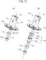
- Fig. 11(a) is a perspective view of the rotating body 130, the connecting member 135, and the shaft portion 311 that are connected to each other.
- Fig. 11(b) is a perspective view illustrating a state in which the connecting member 135, the connecting shaft portion 134, and the shaft portion 311 are separated.
- Fig. 12 is an exploded perspective view of the rotating body 130 and the connecting member 135.
- the rotating body 130 includes a hollow cylindrical base portion 131 and a flange 132 that extends outward from the bottom end of the base portion 131.
- the rotating body 130 is rotatable about the rotational axis AX, which coincides with the central axis of the rotating body 130.
- the rotating body 130 has an internal space 133, which is open at the side at which the flange 132 is provided (see Fig. 3 ).
- the connecting shaft portion 134 which extends along the rotational axis AX, is disposed in the internal space 133.
- the connecting shaft portion 134 has the joining projection 134a that projects downward at the bottom end thereof. As illustrated in Fig. 3 , the joining projection 134a is inserted into the joining recess 313 provided at the top end of the shaft portion 311 of the brake applying unit 210. Thus, the connecting shaft portion 134 and the shaft portion 311 are connected together so as to extend in the rotational axis AX. This connection enables the resistance force (braking torque) generated by the brake applying unit 210 to be transmitted from the shaft portion 311 to the rotating body 130 through the connecting shaft portion 134.
- the connecting member 135 is fixed to the connecting shaft portion 134 and the shaft portion 311, which are connected to each other, so as to externally cover the connecting shaft portion 134 and the shaft portion 311 ( Fig. 3 ).
- the connecting member 135 includes a hollow rod-shaped central spring portion 135a that extends along the rotational axis AX, a first fixed portion 135b provided above the central spring portion 135a, and a second fixed portion 135c provided below the central spring portion 135a.
- the central spring portion 135a is composed of a material having spring characteristics with respect to the central axis direction.
- the first fixed portion 135b is fixed to the connecting shaft portion 134
- the second fixed portion 135c is fixed to the shaft portion 311.
- the central spring portion 135a is disposed to cover the connecting shaft portion 134 and the shaft portion 311.
- annular encoder disc 141 is provided on the bottom surface of the flange 132 of the rotating body 130 so that the encoder disc 141 extends in the circumferential direction of the flange 132.
- the flange 132 includes an outer edge portion 132a on the bottom surface thereof in a region outside the encoder disc 141 so that the outer edge portion 132a extends in the circumferential direction of the flange 132.
- the outer edge portion 132a of the flange 132 is fixed to the upper surface of the back yoke 155 so that the rotating body 130 is attached to and integrated with the rotor of the torque applying unit 150.
- the encoder disc 141 forms the rotation detection unit 140 together with a detection substrate 142 and a detecting element 143.
- the encoder disc 141 has reflective and nonreflective portions that are alternately arranged in the circumferential direction thereof. When the rotating body 130 rotates about the rotational axis AX, the encoder disc 141 rotates about the rotational axis AX together with the rotating body 130.
- the detection substrate 142 is fixed to the upper surface of the third yoke 290 of the brake applying unit 210.
- the detecting element 143 is provided on the detection substrate 142, and is disposed at a position corresponding to the position of the encoder disc 141 in the direction orthogonal to the rotational axis AX.
- the detecting element 143 includes a light emitting element and a light receiving element.
- the light emitting element emits detection light toward the encoder disc 141 in a predetermined area.
- the light receiving element receives light reflected by the reflective portions of the encoder disc 141, and the rotation angle of the encoder disc 141 and the rotating body 130 on which the encoder disc 141 is provided is detected based on the result of the light receiving process.
- the result of the detection is output to the controller 160 ( Fig. 4 ).
- the controller 160 supplies currents controlled based on the detection result obtained by the detecting element 143 to the air-core coils 153a to 153h (torque applying coils) of the coil unit 153 and the two coils 250 and 450 (brake applying coils) of the brake applying unit 210.
- the controller 160 is capable of individually controlling application of current to the torque applying coils and application of current to the brake applying coils.
- the controller 160 is also capable of individually controlling the currents applied to the air-core coils 153a to 153h and the currents applied to the two coils 250 and 450 of the brake applying unit 210.
- the controller 160 is also capable of causing the torque applying unit 150 to generate a driving torque and the brake applying unit 210 to generate a braking force simultaneously or at different times.
- the above-described current control enables the torque applying coils to generate the driving torque and the brake applying unit to generate the braking force at any timing. Accordingly, various operation sensations can be provided to the user.
- the magnet unit 154 and the back yoke 155 which are integrated with each other, are rotated or turned about the rotational axis AX due to the magnetic fields induced by the air-core coils 153a to 153h, which serve as torque applying coils. Accordingly, the rotating body 130, which is fixed to the back yoke 155, receives a driving torque around the rotational axis AX.
- the magnet unit 154 can be rotated or turned about the rotational axis AX with respect to the base plate 151, the fixed member 152, and the coil unit 153 fixed to the fixed portion 120. Accordingly, the back yoke 155 fixed to the magnet unit 154 is also rotated or turned, and the driving torque for rotating or turning the rotating body 130 fixed to the back yoke 155 is transmitted to the rotating body 130.
- the direction of the driving torque is controlled based on the directions in which the currents are applied in the four patterns illustrated in Figs. 5(a) to 5(d) .
- a driving torque is generated in the reverse direction, so that the rotating body 130 is rotated or turned in the reverse direction.
- a driving torque of any magnitude can be applied to the rotating body 130 by controlling the magnitudes of the currents applied to the air-core coils 153a to 153h with the controller 160.
- variation in the driving torque depending on the relative positions between the air-core coils 153a to 153h and the magnets can be reduced.
- a predetermined operation sensation can be provided to the operator that operates the rotating body 130.
- the input device 110 of the present embodiment is structured such that magnetic cores having salient poles are not provided and that the air-core coils having no salient poles are used. Therefore, no cogging torque is generated in a rotating operation in which the coils are not energized.
- the air-core coils 153a to 153h are held by the fixed member 152 composed of a non-magnetic body. Therefore, the magnetic attraction force between the magnets and the magnetic bodies may be set to 0. Thus, the rotating operation in which the air-core coils 153a to 153h are not energized can be performed in a state close to an ideal state, that is, a so-called torque-free state.
- the combination of the number of air-core coils included in the coil unit 153 and the number of magnets included in the magnet unit 154 is not limited to that in the present embodiment.
- the air-core coils may be replaced by, for example, coils formed by winding wires around non-magnetic cores as long as an equivalent magnetic circuit can be obtained.
- the rotating body 130 receives a braking force from the brake applying unit 210 through the connecting shaft portion 134.
- the brake applying unit 210 will now be described.
- the first coil 250 and the second coil 450 are connected to the controller 160, and the controller 160 controls currents to be applied to the two coils 250 and 450 and applies the currents to the two coils 250 and 450.
- currents are simultaneously applied to the two coils 250 and 450 so that magnetic flux extends in the direction away from the central axis 211 in each of the two magnetic discs 320 and 520.
- the applied currents may instead be controlled so that magnetic flux extends through the two magnetic discs 320 and 520 in the opposite directions.
- a current may be applied to only one of the coils.
- the currents applied to the two coils 250 and 450 may be either the same or different.
- the controller 160 applies currents to the two coils 250 and 450, which serve as brake applying coils, the above-described magnetic fields are generated and magnetic flux passes through each of the magnetic discs 320 and 520 in the up-down direction.
- the density of magnetic flux extending in the radial direction is very low in the magnetic discs 320 and 520.
- the connecting shaft portion 134 connected to the shaft portion 311 hardly receives a braking force. Therefore, the operator can operate and rotate the rotating body 130 without receiving a large braking force from the brake applying unit 210.
- the operator feels a greater resistance force than when no magnetic fields are generated.
- the resistance force felt by the operator can be increased or reduced, so that the operation sensation provided to the operator can be varied.
- variable control of the driving torque applied by the torque applying unit 150 but also variable control of the braking force of a desired magnitude can be achieved, so that various operation sensations can be provided to the operator that operates the rotating body 130.
- the controller 160 applies predetermined currents to the two coils 250 and 450, which serve as brake applying coils, when the rotation angle detected by the detecting element 143 reaches a predetermined angle set in advance. Accordingly, the shaft portion 311 applies a strong braking force to the rotating body 130 through the connecting shaft portion 134, so that the operator that operates the rotating body 130 feels an operation sensation as if the rotating body 130 has been stopped by an imaginary stopper (end-stop state).
- the above-described input device 110 has the following effects.
- the input device according to the present invention is useful in that the size thereof in the direction of the rotational axis can be reduced.
Landscapes
- Engineering & Computer Science (AREA)
- General Engineering & Computer Science (AREA)
- Mechanical Engineering (AREA)
- Physics & Mathematics (AREA)
- Power Engineering (AREA)
- Electromagnetism (AREA)
- General Physics & Mathematics (AREA)
- Automation & Control Theory (AREA)
- Braking Arrangements (AREA)
- Mechanical Control Devices (AREA)
Abstract
Description
- The present invention relates to an input device capable of varying rotational resistance by using magnetic viscous fluid.
- An operation sensation imparting input device described in PTL 1 includes a rotary operation part; an encoder that detects a rotational state of the operation part; an armature rotor that rotates together with the operation part; an electromagnetic brake that applies rotational resistance to the operation part through the armature rotor; an electric motor that imparts autonomous rotation force to the operation part through a rotating shaft; and a controller that drives the electromagnetic brake and the electric motor. When rotational resistance is to be applied, the controller drives the electromagnetic brake to reduce power consumption. The controller is also capable of driving the electric motor to cause the operation part to rotate autonomously. The electromagnetic brake includes a winding disposed outside the electric motor so that the overall size of the device is reduced in a direction of a rotational axis.
- PTL 1: Japanese Unexamined Patent Application Publication No.
2010-211270 - The operation sensation imparting input device described in PTL 1 is structured such that the armature rotor is disposed between the electric motor and the operation part. Therefore, reduction in the overall size in the direction of the rotational axis is limited by the sizes of these components.
- Accordingly, an object of the present invention is to provide an input device suitable for size reduction in a direction of a rotational axis of a rotating body.
- To achieve the above-described object, an input device according to the present invention includes a fixed portion; a rotating body supported such that the rotating body is rotatable about a rotational axis; a rotation detection unit configured to detect a rotation of the rotating body; a brake applying unit configured to apply a braking force to the rotating body; and a torque applying unit configured to apply a driving torque for rotating the rotating body about the rotational axis to the rotating body. The brake applying unit includes a rotary plate rotatable together with the rotating body, magnetic viscous fluid disposed in a gap between the fixed portion and the rotary plate, and a brake applying coil configured to apply a magnetic field to the magnetic viscous fluid. The torque applying unit includes a stator and a rotor supported such that the rotor is rotatable with respect to the stator. One of the stator and the rotor of the torque applying unit includes a magnet and other of the stator and the rotor of the torque applying unit includes torque applying coils of at least two phases, the torque applying coils inducing magnetic fields for generating the driving torque applied to the rotating body. A controller is provided to control currents applied to the brake applying coil and the torque applying coils. The torque applying unit is disposed to surround an outer periphery of the brake applying unit.
- Accordingly, size reduction in the direction of the rotational axis of the rotating body can be achieved. In addition, since the torque applying unit and the brake applying unit can be disposed close to each other, size reduction in a direction orthogonal to the rotational axis can also be achieved.
- In the input device according to the present invention, preferably, the controller is capable of individually controlling a current applied to the brake applying coil and currents applied to the torque applying coils, and is capable of simultaneously generating the braking force and the driving torque.
- In this case, various operation sensations can be provided to an operator.
- In the input device according to the present invention, preferably, the rotor is supported such that the rotor is rotatable together with the rotating body, and includes an annular back yoke and a plurality of permanent magnets provided on an outer periphery of the back yoke and arranged such that poles of different polarities are alternately arranged in a circumferential direction of the back yoke, and the stator is disposed to surround a radially outer periphery of the rotor and face the permanent magnets, and includes coils formed of non-magnetic windings and a fixed member to which the coils are fixed, the coils serving as the torque applying coils.
- In this case, magnetic cores having salient poles are not provided, and coils having no salient poles are used. Therefore, no cogging torque is generated in a rotating operation in which the coils are not energized. As a result, the operation sensations are not adversely affected by a cogging torque. In addition, when the fixed member of the stator is formed of a non-magnetic body, not only cogging due to variation in magnetic attraction force but also a rotational resistance due to a magnetic attraction force of a permanent magnet can be prevented.
- In the input device according to the present invention, preferably, the torque applying coils include eight torque applying coils, and currents are applied to the torque applying coils such that adjacent ones of the torque applying coils generate magnetic fields in opposite directions. Two adjacent ones of the torque applying coils and two of the torque applying coils symmetric to the two adjacent ones of the torque applying coils about the rotational axis simultaneously receive currents in phase A, and remaining four of the torque applying coils simultaneously receive currents in phase B.
- In this case, the curvature of the torque applying unit can be reduced, so that the torque applying unit can be easily manufactured. In addition, the area of the region in which the magnetic flux generated by the magnets extends through the torque applying coils can be increased without increasing the overall length in the direction of the rotational axis, and the driving torque can be increased accordingly.
- In the input device according to the present invention, preferably, the brake applying unit includes a shaft portion configured to rotate together with the rotary plate, and the shaft portion is connected to the rotating body by a connecting member having spring characteristics.
- In this case, a phase difference can be generated between the rotating operation of the shaft portion of the brake applying unit and the rotating operation of the rotating body. Therefore, even when the shaft portion of the brake applying unit is stopped in the end-stop state, if a low torque is applied to the rotating body, the shaft portion is twisted in response to the rotation of the rotating body. Accordingly, the rotation of the rotating body can be detected by the rotation detection unit, and a smooth operation sensation with small roughness can be provided to the operator by cancelling the end-stop state based on the result of the detection.
- In the input device according to the present invention, preferably, the torque applying coils and the brake applying coil are arranged such that a center line of each of torque applying coils is orthogonal to a center line of the brake applying coil.
- In this case, even when the torque applying coils and the brake applying coil are disposed close to each other, interference between the magnetic fields generated thereby can be reduced. Thus, the influence of the magnetic fields generated by the torque applying coils on the magnetic viscous fluid of the brake applying unit can be reduced.
- According to the present invention, size reduction in the direction of the rotational axis of the rotating body can be achieved.
-
- [
Fig. 1] Figs. 1(a) and 1(b) are perspective views illustrating the structure of an input device according to an embodiment of the present invention. - [
Fig. 2] Fig. 2 is an exploded perspective view of the input device illustrated inFigs. 1(a) and 1(b) . - [
Fig. 3] Fig. 3 is a sectional view of the input device according to the embodiment of the present invention taken along a rotational axis of a rotating body. - [
Fig. 4] Fig. 4 is a functional block diagram of the input device according to the embodiment of the present invention. - [
Fig. 5] Figs. 5(a) to 5(d) are plan views illustrating the relationships between air-core coils of a coil unit and magnets of a magnet unit according to the embodiment of the present invention. - [
Fig. 6] Fig. 6(a) is a perspective view of a brake applying unit according to the embodiment of the present invention viewed from above, andFig. 6(b) is a perspective view of the brake applying unit viewed from below. - [
Fig. 7] Fig. 7 is an exploded perspective view of the brake applying unit according to the embodiment of the present invention viewed from above. - [
Fig. 8] Fig. 8 is an exploded perspective view of the brake applying unit according to the embodiment of the present invention viewed from above. - [
Fig. 9] Fig. 9 is a sectional view ofFig. 10(a) taken along line IX-IX'. - [
Fig. 10] Fig. 10 is an enlarged view of part ofFig. 9 . - [
Fig. 11] Fig. 11(a) is a perspective view of the rotating body, a connecting member, and a shaft portion according to the embodiment of the present invention that are connected to each other, andFig. 11(b) is a perspective view illustrating a state in which the connecting member, a connecting shaft portion, and the shaft portion are separated. - [
Fig. 12] Fig. 12 is an exploded perspective view of the rotating body and the connecting member according to the embodiment of the present invention. - An input device according to an embodiment of the present invention will now be described in detail with reference to the drawings.
-
Figs. 1(a) and 1(b) are perspective views illustrating the structure of aninput device 110 according to an embodiment of the present invention.Fig. 2 is an exploded perspective view of theinput device 110 illustrated inFigs. 1(a) and 1(b) .Fig. 3 is a sectional view of theinput device 110 taken along a rotational axis AX of a rotatingbody 130.Fig. 4 is a functional block diagram of theinput device 110. In the following description, the direction of the rotational axis AX, which is the rotation center of the rotatingbody 130, is referred to as an up-down direction, and a direction orthogonal to the rotational axis AX is referred to as a radial direction. The up-down direction may be set to any direction depending on, for example, the orientation of the input device. A view in the direction of the rotational axis AX is referred to as a plan view, and a direction of a circumference of a circle centered on the rotational axis AX in a plan view is referred to as a circumferential direction. - As illustrated in
Fig. 2 , theinput device 110 according to the present embodiment includes afixed portion 120, therotating body 130, a connectingmember 135, arotation detection unit 140, atorque applying unit 150, and abrake applying unit 210, and is used in an assembled state illustrated inFigs. 1(a) and 1(b) . Theinput device 110 further includes acontroller 160 illustrated inFig. 4 . - As illustrated in
Fig. 2 , the fixedportion 120 is a plate member composed of a non-magnetic body. The fixedportion 120 has anopening 121 that extends therethrough in the up-down direction in a central region thereof in plan view. Ashaft portion 311 of thebrake applying unit 210 extends to the outside through the opening 121 (seeFig. 1(b) ). - As illustrated in
Fig. 2 , thetorque applying unit 150 includes abase plate 151, a fixedmember 152, acoil unit 153, amagnet unit 154, aback yoke 155, and acoil holder 156, and is substantially symmetrical about the rotational axis AX. The fixedmember 152, which is made of a non-magnetic material, and thecoil unit 153, which is fixed to the inner peripheral surface of the fixedmember 152, form a stator. Themagnet unit 154, which is disposed to face the inner peripheral surface of thecoil unit 153, and theback yoke 155, which is fixed to the inner peripheral surface of themagnet unit 154, form a rotor. The rotor is supported such that the rotor is rotatable with respect to the stator. - The
base plate 151 is substantially circular plate-shaped, and is fixed to the fixedportion 120 so that the central axis thereof coincides with the rotational axis AX. As illustrated inFigs. 2 and3 , acylindrical pretensioner 151a is disposed concentrically to thebase plate 151 at the center of thebase plate 151. As illustrated inFig. 3 , thepretensioner 151a is fixed such that thepretensioner 151a extends through the fixedportion 120 and thebase plate 151 in the up-down direction. Thepretensioner 151a radially supports ashaft 310 that extends therethrough. - As illustrated in
Figs. 2 and3 , thebase plate 151 has positioningrecesses 151b arranged along the outer periphery thereof. The positioning recesses 151b serve as coil holders for positioning and holding lower portions of air-core coils 153a to 153h (described below). Thebase plate 151 also has anouter edge recess 151c disposed outside the positioning recesses 151b and recessed further downward from the positioning recesses 151b. Thus, thebase plate 151 is substantially symmetrical about the rotational axis AX. As illustrated inFig. 3 , lower portions of thecoil unit 153 are inserted into the positioning recesses 151b, so that thecoil unit 153 is positioned. - As illustrated in
Figs. 1(b) and3 , a plurality ofconductive pins 122 are provided to extend through thebase plate 151 in the up-down direction. Thepins 122 are exposed to the outside through theopening 121 in the fixedportion 120 at the bottom of theinput device 110. Thecontroller 160 supplies predetermined currents to thecoil unit 153, afirst coil 250 of thebrake applying unit 210, and asecond coil 450 of thebrake applying unit 210 through thepins 122. - As illustrated in
Fig. 3 , a lower portion of the fixedmember 152, which has a cylindrical shape, is fitted to theouter edge recess 151c of thebase plate 151, so that the fixedmember 152 is positioned along the outer periphery of thebase plate 151 and fixed to thebase plate 151 and the fixedportion 120. Thus, the fixedmember 152 is substantially symmetrical about the rotational axis AX. As illustrated inFigs. 3 and5 , eight air-core coils member 152. The eight air-core coils 153a to 153h form thecoil unit 153. - The above-described eight air-
core coils peripheral surface 152a (seeFig. 2 ) of the fixedmember 152 and arranged in the circumferential direction thereof. The eight air-core coils 153a to 153h are arranged at constant angular intervals along a circle centered on the rotational axis AX, and are each wound around a center line extending radially from the rotational axis AX toward the circumference of the circle. Thus, thecoil unit 153 is substantially symmetrical about the rotational axis AX. The air-core coils 153a to 153h each receive a current controlled by the controller 160 (seeFig. 4 ). - As illustrated in
Fig. 2 andFigs. 5(a) to 5(d) , themagnet unit 154 includes sixmagnets magnets 154a to 154f are disposed inside the air-core coils 153a to 153h of thecoil unit 153 to face the air-core coils 153a to 153h such that themagnets 154a to 154f are radially spaced from the air-core coils 153a to 153h by a predetermined distance. In addition, as illustrated inFigs. 2 and3 , themagnets 154a to 154f are provided on an outerperipheral surface 155a of theback yoke 155, which has a cylindrical shape, and arranged in the circumferential direction thereof. Themagnets 154a to 154f are arranged at constant angular intervals along a circle centered on the rotational axis AX, and each have magnetic poles arranged radially in a direction from the rotational axis AX toward the circumference of the circle. The magnetic poles are arranged such that opposite magnetic poles are disposed adjacent to each other. Thus, themagnet unit 154 and theback yoke 155 are each substantially symmetrical about the rotational axis AX. For simplification, only the magnetic poles at the outer periphery are illustrated inFigs. 5(a) to 5(d) . For example, themagnet 154a has an S pole at the outer end and an N pole at the inner end adjacent to the rotational axis AX. -
Figs. 5(a) to 5(d) are plan views illustrating the relationships between the air-core coils 153a to 153h of thecoil unit 153 and themagnets 154a to 154f of themagnet unit 154.Figs. 5(a) to 5(d) illustrate states in which themagnets 154a to 154f are in stable positions, that is, positions where the maximum torque is generated, when the air-core coils 153a to 153h are in different energization states.Figs. 5(a) to 5(d) show the directions in which currents applied to the air-core coils 153a to 153h flow along the up-down direction (direction of the rotational axis AX): "×" shows the front-to-back direction in each figure, and "•" (black circle) shows the back-to-front direction in each figure. - As illustrated in
Fig. 3 , the eight air-core coils 153a to 153h are positioned in the up-down direction and held by thecoil holder 156 and thebase plate 151. As illustrated inFig. 2 , thecoil holder 156 is ring-shaped, and is fixed to the outer peripheral surface of the fixedmember 152 at the top end thereof so that the central axis of thecoil holder 156 coincides with the rotational axis AX. Thus, thecoil holder 156 is substantially symmetrical about the rotational axis AX. As described above, thebase plate 151, the fixedmember 152, thecoil unit 153, themagnet unit 154, theback yoke 155, and thecoil holder 156 are each substantially symmetrical about the rotational axis AX. Therefore, the overall structure of thetorque applying unit 150 is substantially symmetrical about the rotational axis AX. - As illustrated in
Figs. 5(a) to 5(d) , currents are applied to the air-core coils 153a to 153h in groups of four, more specifically, to two adjacent air-core coils and other two adjacent air-coils that are symmetric to the first two adjacent air-core coils about the rotational axis AX. - Referring to
Figs. 5(a) and 5(b) , the state in which currents are applied to a group of coils including two adjacent air-core coils core coils core coils Figs. 5(c) and 5(d) , the state in which currents are applied to the other group of coils that receive no currents in phase A, that is, two adjacent air-core coils core coils core coils core coils core coils - Energization of the air-
core coils 153a to 153h is controlled so that switching between the above-described two phases, that is, phase A and phase B, occurs every time therotating body 130 rotates 120 degrees. Accordingly, switching between the states illustrated inFigs. 5(a) to 5(d) occurs three times during one revolution of therotating body 130 at intervals of 120 degrees. - In the state illustrated in
Fig. 5(a) , the two adjacent air-core coils core coil 153f, which is symmetric to the air-core coil 153b about the rotational axis AX, receives a current in a direction opposite to that of the current applied to the air-core coil 153b, and the air-core coil 153g, which is symmetric to the air-core coil 153c, receives a current in a direction opposite to that of the current applied to the air-core coil 153c. Accordingly, as shown by the arrows inFig. 5(a) , the adjacent coils generate magnetic fields in the opposite directions, and two coils that are symmetric to each other about the rotational axis AX generate magnetic fields in the same direction. - The relationship between the currents applied to the air-core coils and the generated magnetic fields is similar in each of
Figs. 5(b), 5(c), and 5(d) . - The
magnet unit 154 can be rotated or turned about the rotational axis AX with respect to thecoil unit 153, which is fixed to thebase plate 151, the fixedmember 152, and the fixedportion 120, by applying currents to the air-core coils 153a to 153h in four patterns illustrated inFigs. 5(a) to 5(d) . Accordingly, theback yoke 155, to which themagnet unit 154 is fixed, is also rotated or turned. Therotating body 130, which will be described below, is concentrically fixed to theback yoke 155, and rotating or turning driving torque is transmitted to therotating body 130 when themagnet unit 154 is rotated or turned. -
Fig. 6(a) is a perspective view of thebrake applying unit 210 viewed from above, andFig. 6(b) is a perspective view of thebrake applying unit 210 viewed from below.Figs. 7 andFig. 8 are exploded perspective views of thebrake applying unit 210 viewed from above.Fig. 7 is a perspective view of anupper section 210A that is above position A, andFig. 8 is a perspective view of alower section 210B that is blow position A.Fig. 9 is a sectional view ofFig. 6(a) taken along line IX-IX', and conceptually illustrates magnetic fields generated by the twocoils Fig. 10 is an enlarged view of part ofFig. 9 . In the following description, the direction of acentral axis 211 is referred to as a first direction D1 (Figs. 6 and9 ), and a radial direction orthogonal to thecentral axis 211 is referred to as a second direction D2 (Figs. 6 and9 ). A view from above in the direction of thecentral axis 211 may be referred to as a plan view. InFigs. 7 and8 , some screws and magnetic viscous fluid are omitted. - As illustrated in
Figs. 6(a) and 6(b) , thebrake applying unit 210 includes aholder unit 220 and arotation operation unit 300, and is substantially symmetrical about thecentral axis 211. Therotation operation unit 300 includes theshaft 310 and twomagnetic discs 320 and 520 (rotary plates), which are connected together to be capable of rotating together in both directions about the central axis 211 (rotational axis). - As illustrated in
Fig. 3 , thebrake applying unit 210 is disposed in theback yoke 155 such that the outer peripheral surfaces of anouter yoke 232, anannular member 270, and anouter yoke 432, which will be described below, face the inner peripheral surface of theback yoke 155 and are spaced from the inner peripheral surface of theback yoke 155. In other words, thetorque applying unit 150 is disposed to surround the outer periphery of thebrake applying unit 210. Thebrake applying unit 210 is disposed such that thecentral axis 211 thereof coincides with the rotational axis AX of therotating body 130, and the bottom surface of athird yoke 490 of thebrake applying unit 210 is fixed to thebase plate 151. In this state, the first direction D1 is the direction of the rotational axis AX, and the second direction D2 is orthogonal to the direction of the rotational axis AX. - The
rotation operation unit 300 is rotatably supported on theholder unit 220 by tworadial bearings pushers 352 and 552 (seeFigs. 7 and8 ). As illustrated inFig. 10 , twogaps brake applying unit 210 are filled with magneticviscous fluids - In the
upper section 210A illustrated inFig. 7 , theholder unit 220 includes afirst yoke 230, asecond yoke 240, thefirst coil 250, which serves as a brake applying coil, a sealingmember 260, and athird yoke 290, which serves as an upper casing. As illustrated inFig. 7 , thefirst yoke 230 is disposed on one side of themagnetic disc 320 and thesecond yoke 240 is disposed on the other side of themagnetic disc 320 in the first direction D1. As described below, thefirst yoke 230, thesecond yoke 240, thefirst coil 250, the sealingmember 260, and thethird yoke 290 are each substantially symmetrical about the central axis 211 (rotational axis). Therefore, the overall structure in theupper section 210A of theholder unit 220 is substantially symmetrical about the central axis 211 (rotational axis). - In the
lower section 210B illustrated inFig. 8 , theholder unit 220 includes afirst yoke 430, asecond yoke 440, thesecond coil 450, which serves as a brake applying coil, a sealingmember 460, and thethird yoke 490, which serves as a lower casing. As illustrated inFig. 8 , thefirst yoke 430 is disposed on one side of themagnetic disc 520 and thesecond yoke 440 is disposed on the other side of themagnetic disc 520 in the first direction D1. As described below, thefirst yoke 430, thesecond yoke 440, thesecond coil 450, the sealingmember 460, and thethird yoke 490 are each substantially symmetrical about the central axis 211 (rotational axis). Therefore, the overall structure of thelower section 210B of theholder unit 220 is substantially symmetrical about the central axis 211 (rotational axis). - The
holder unit 220 includes theannular member 270 that extends in both theupper section 210A and thelower section 210B. In theupper section 210A, thefirst yoke 230, thesecond yoke 240, and thethird yoke 290 are formed separately. In thelower section 210B, thefirst yoke 430, thesecond yoke 440, and thethird yoke 490 are formed separately. However, some of these yokes may instead be formed integrally with each other. - As illustrated in
Fig. 7 , thefirst coil 250 in theupper section 210A has an annular shape. Thefirst coil 250 is a coil including a conductive wire wound around thecentral axis 211. As illustrated inFig. 8 , thesecond coil 450 in thelower section 210B also has an annular shape. Thesecond coil 450 is also a coil including a conductive wire wound around thecentral axis 211. Thus, thefirst coil 250 and thesecond coil 450 are each substantially symmetrical about the central axis 211 (rotational axis). The twocoils controller 160 along paths that are not illustrated. Thecoils - As illustrated in
Fig. 7 , thefirst yoke 230 in theupper section 210A includes aninner yoke 231 as an inner peripheral member and theouter yoke 232 as an outer peripheral member. Theinner yoke 231 and theouter yoke 232 are concentrically arranged about thecentral axis 211. As illustrated inFig. 8 , thefirst yoke 430 in thelower section 210B includes aninner yoke 431 as an inner peripheral member and theouter yoke 432 as an outer peripheral member. Theinner yoke 431 and theouter yoke 432 are concentrically arranged about thecentral axis 211. Thus, the twofirst yokes - As illustrated in
Fig. 7 , theinner yoke 231 in theupper section 210A includes acylindrical portion 231a and a flange-shapedportion 231b (Fig. 10 ) having an annular shape in plan view and extending radially outward from a lower surface of thecylindrical portion 231a. The outer diameter of the outer peripheral surface of an upper portion of thecylindrical portion 231a and the inner diameter of the inner peripheral surface of thecylindrical portion 231a vary depending on the positions in the up-down direction. As illustrated inFig. 8 , theinner yoke 431 in thelower section 210B includes acylindrical portion 431a and a flange-shapedportion 431b (Fig. 10 ) having an annular shape in plan view and extending radially outward from an upper surface of thecylindrical portion 431a. The outer diameter of the outer peripheral surface of a lower portion of thecylindrical portion 431a and the inner diameter of the inner peripheral surface of thecylindrical portion 431a vary depending on the positions in the up-down direction. - As illustrated in
Fig. 7 , theouter yoke 232 in theupper section 210A includes acylindrical portion 232a and anedge portion 232b having an annular shape in plan view and extending radially inward from a lower surface of thecylindrical portion 232a. Referring toFig. 9 or10 , the inner peripheral surface of thecylindrical portion 232a of theouter yoke 232 faces the outer peripheral surface of thecylindrical portion 231a of theinner yoke 231 so that afirst space 233 having an annular shape is formed therebetween. Thefirst coil 250, which serves as a brake applying coil, is disposed in thefirst space 233. Thethird yoke 290, which is substantially circular plate-shaped, is placed on theinner yoke 231 from above, and is fixed to theinner yoke 231 and theouter yoke 232 withscrews 291 so that thefirst space 233 is closed and that theinner yoke 231, theouter yoke 232, and thethird yoke 290 form a magnetic path that surrounds thefirst coil 250. Thethird yoke 290 is disposed such that the center thereof is on thecentral axis 211, and is therefore substantially symmetrical about the central axis 211 (rotational axis). - As illustrated in
Fig. 8 , theouter yoke 432 in thelower section 210B includes acylindrical portion 432a and anedge portion 432b having an annular shape in plan view and extending radially inward from an upper surface of thecylindrical portion 432a. Referring toFig. 9 or10 , the inner peripheral surface of thecylindrical portion 432a of theouter yoke 432 faces the outer peripheral surface of thecylindrical portion 431a of theinner yoke 431 so that a first space 433 having an annular shape is formed therebetween. Thesecond coil 450, which serves as a brake applying coil, is disposed in the first space 433. Thethird yoke 490, which is substantially circular plate-shaped, is disposed below theinner yoke 431 and fixed to theinner yoke 431 and theouter yoke 432 withscrews 491 so that the first space 433 is closed and that theinner yoke 431, theouter yoke 432, and thethird yoke 490 form a magnetic path that surrounds thesecond coil 450. Thethird yoke 490 is disposed such that the center thereof is on thecentral axis 211, and is therefore substantially symmetrical about the central axis 211 (rotational axis). - As illustrated in
Fig. 9 , in theupper section 210A,annular spaces edge portion 232b of theouter yoke 232 and the outer peripheral surface of the flange-shapedportion 231b of theinner yoke 231. Thesecond space 234 is connected to the above-describedfirst space 233, and thethird space 235 is connected to thesecond space 234. - As illustrated in
Fig. 10 , the inner peripheral surface of the flange-shapedportion 231b includes afirst surface 231c that is inclined outward in the radial direction (direction D2 inFig. 9 ) and downward and asecond surface 231d that extends in the first direction (direction D1 inFig. 10 ) from the bottom end of thefirst surface 231c. The inner peripheral surface of theedge portion 232b includes afirst surface 232c that is inclined inward in the radial direction and downward and asecond surface 232d that extends in the first direction D1 from the bottom end of thefirst surface 232c. Thefirst surface 231c of theinner yoke 231 and thefirst surface 232c of theouter yoke 232 are disposed at positions corresponding to each other in the first direction D1 so as to form thesecond space 234 therebetween. Thesecond space 234 is a space in which no object is disposed, and forms a magnetic gap whose width in the radial direction decreases toward the bottom. In other words, the magnetic gap is shaped such that the width thereof in the radial direction increases toward thefirst coil 250, that is, toward the top. - The
second surface 231d and thesecond surface 232d are arranged to extend parallel to each other and face each other in the radial direction at positions corresponding to each other in the first direction D1, thereby forming thethird space 235 therebetween. The sealingmember 260, which is composed of a non-magnetic body, is disposed in thethird space 235, so that thesecond space 234 and thethird space 235 form a magnetic gap. - The sealing
member 260 has an annular shape and is made of a non-magnetic material, such as a synthetic resin. The sealingmember 260 is formed by, for example, filling thethird space 235 with a material in a fluid state and solidifying the material. Alternatively, an elastic material formed in an annular shape may be fitted into thethird space 235. Alternatively, a non-elastic material may be formed into an annular shape and fixed with an adhesive. The sealingmember 260 disposed in thethird space 235 is substantially symmetrical about the central axis 211 (rotational axis). - A
lower surface 231e of theinner yoke 231 and alower surface 232e of theouter yoke 232 form a facing surface that faces the magnetic disc 320 (Figs. 9 and10 ). The facing surface is divided into inner and outer regions by the magnetic gap formed by thesecond space 234 and thethird space 235. The inner region corresponds to thelower surface 231e of theinner yoke 231, and the outer region corresponds to thelower surface 232e of theouter yoke 232. The magnetic gap is provided at a position such that the inner region of the facing surface that is inside the magnetic gap and the outer region of the facing surface that is outside the magnetic gap have substantially the same area. - The
inner yoke 231 and theouter yoke 232 have substantially the same cross-sectional area along a plane orthogonal to thecentral axis 211 at the position where thefirst coil 250 is disposed. Accordingly, a magnetic field having an optimum structure can be realized until the saturation magnetic flux density is reached. - As illustrated in
Fig. 9 , in thelower section 210B,annular spaces edge portion 432b of theouter yoke 432 and the outer peripheral surface of the flange-shapedportion 431b of theinner yoke 431. Thesecond space 434 is connected to the above-described first space 433, and thethird space 435 is connected to thesecond space 434. - As illustrated in
Fig. 10 , the inner peripheral surface of the flange-shapedportion 431b includes afirst surface 431c that is inclined outward in the radial direction and upward and asecond surface 431d that extends in the first direction D1 from the top end of thefirst surface 431c. The inner peripheral surface of theedge portion 432b includes afirst surface 432c that is inclined inward in the radial direction and upward and asecond surface 432d that extends in the first direction D1 from the top end of thefirst surface 432c. Thefirst surface 431c of theinner yoke 431 and thefirst surface 432c of theouter yoke 432 are disposed at positions corresponding to each other in the first direction D1 so as to form thesecond space 434 therebetween. Thesecond space 434 is a space in which no object is disposed, and forms a magnetic gap whose width in the radial direction decreases toward the top. In other words, the magnetic gap is shaped such that the width thereof in the radial direction increases toward thesecond coil 450, that is, toward the bottom. - The
second surface 431d and thesecond surface 432d are arranged to extend parallel to each other and face each other in the radial direction at positions corresponding to each other in the first direction D1, thereby forming thethird space 435 therebetween. The sealingmember 460, which is composed of a non-magnetic body, is disposed in thethird space 435, so that thesecond space 434 and thethird space 435 form a magnetic gap. The sealingmember 460 and the above-describedsealing member 260 have the same structure and are made of the same material. Thus, the sealingmember 460 disposed in thethird space 435 is substantially symmetrical about the central axis 211 (rotational axis). - An
upper surface 431e of theinner yoke 431 and anupper surface 432e of theouter yoke 432 form a facing surface that faces the magnetic disc 520 (Figs. 9 and10 ). The facing surface is divided into inner and outer regions by the magnetic gap formed by thesecond space 434 and thethird space 435. The inner region corresponds to theupper surface 431e of theinner yoke 431, and the outer region corresponds to theupper surface 432e of theouter yoke 432. The magnetic gap is provided at a position such that the inner region of the facing surface that is inside the magnetic gap and the outer region of the facing surface that is outside the magnetic gap have substantially the same area. - The
inner yoke 431 and theouter yoke 432 have substantially the same cross-sectional area along a plane orthogonal to thecentral axis 211 at the position where thesecond coil 450 is disposed. Accordingly, a magnetic field having an optimum structure can be realized until the saturation magnetic flux density is reached. - As illustrated in
Fig. 9 , in theupper section 210A, the width of thefirst space 233 is set to be greater than the width of thesecond space 234 in the radial direction (second direction D2). In addition, acenter position 235x of thethird space 235 in the radial direction is located outside acenter position 233x of thefirst space 233 in the radial direction. Similarly, in thelower section 210B, the width of the first space 433 is set to be greater than the width of thesecond space 434. In addition, the center position of thethird space 435 in the radial direction coincides with the above-describedcenter position 235x, and is located outside the above-describedcenter position 233x, which coincides with the center position of the first space 433 in the radial direction. - Accordingly, in the
upper section 210A, thefirst surface 231c of theinner yoke 231 and thefirst surface 232c of theouter yoke 232 have different inclination angles with respect to the first direction D1, and thefirst surface 231c of theinner yoke 231 has a greater inclination angle. In other words, thefirst surface 231c of theinner yoke 231 has a smaller inclination angle with respect to the radial direction. Similarly, in thelower section 210B, thefirst surface 431c of theinner yoke 431 and thefirst surface 432c of theouter yoke 432 have different inclination angles with respect to the first direction D1, and thefirst surface 431c of theinner yoke 431 has a greater inclination angle. In other words, thefirst surface 431c of theinner yoke 431 has a smaller inclination angle with respect to the radial direction. - As illustrated in
Fig. 9 , theinner yoke 231 and theouter yoke 232 in theupper section 210A are shaped such that thecenter position 235x of thethird space 235 in the radial direction is located outside the center of the overall body of thefirst yoke 230 in the radial direction. Accordingly, thelower surface 231e serving as a facing surface of theinner yoke 231 that faces themagnetic disc 320 and thelower surface 232e serving as a facing surface of theouter yoke 232 that faces themagnetic disc 320 have substantially the same area in plan view. Thus, the magnetic flux density in the region inside the magnetic gap and that in the region outside the magnetic gap are substantially equal to each other. - The
inner yoke 431 and theouter yoke 432 in thelower section 210B are also shaped such that the above-describedcenter position 235x, which coincides with the center position of thethird space 435 in the radial direction, is located outside the center of the overall body of thefirst yoke 430 in the radial direction. Accordingly, theupper surface 431e serving as a facing surface of theinner yoke 431 that faces themagnetic disc 520 and theupper surface 432e serving as a facing surface of theouter yoke 432 that faces themagnetic disc 520 have substantially the same area in plan view. Thus, the magnetic flux density in the region inside the magnetic gap and that in the region outside the magnetic gap are substantially equal to each other. - As illustrated in
Fig. 7 , thesecond yoke 240 in theupper section 210A has the shape of a circular plate, and is disposed below thefirst yoke 230 so that the center of the circular plate is on thecentral axis 211. Thesecond yoke 240 has atop surface 241 that is orthogonal to the up-down direction, which is the direction of thecentral axis 211. Thesecond yoke 240 has anannular hole 242 that surrounds thecentral axis 211 and extends through thesecond yoke 240 in the up-down direction. As illustrated inFig. 8 , thesecond yoke 440 in thelower section 210B has the shape of a circular plate, and is disposed above thefirst yoke 430 so that the center of the circular plate is on thecentral axis 211. Thesecond yoke 440 has abottom surface 441 that is orthogonal to the up-down direction, which is the direction of thecentral axis 211. Thesecond yoke 440 has anannular hole 442 that surrounds thecentral axis 211 and extends through thesecond yoke 440 in the up-down direction. The twosecond yokes - As illustrated in
Fig. 9 , thesecond yoke 240 and thesecond yoke 440 are stacked in the first direction D1 such that thesecond yoke 240 is disposed above thesecond yoke 440, and theshaft portion 311 of theshaft 310 is inserted through thehole 242 in thesecond yoke 240 and thehole 442 in thesecond yoke 440. Theshaft portion 311 is disposed to extend in the first direction D1, and has aflange portion 312 at substantially the center thereof in the extending direction. Theflange portion 312 is flange-shaped and extends outward from the outer peripheral surface of theshaft portion 311. The thickness of theflange portion 312 in the first direction D1 is greater than the total thickness of thesecond yoke 240 and thesecond yoke 440 by a predetermined amount. The predetermined amount corresponds to the dimensions of the gaps between thesecond yoke 240 and themagnetic disc 320 and between thesecond yoke 440 and themagnetic disc 520. - The shapes of the
yokes - As illustrated in
Fig. 10 , in theupper section 210A, abottom surface 236 of thefirst yoke 230 and alower surface 261 of the sealingmember 260 are substantially parallel to thetop surface 241 of thesecond yoke 240, and themagnetic disc 320 is disposed between thebottom surface 236 and thetop surface 241. Thegap 280 is formed between themagnetic disc 320 and thebottom surface 236 and between themagnetic disc 320 and thetop surface 241. In thelower section 210B, atop surface 436 of thefirst yoke 430 and anupper surface 461 of the sealingmember 460 are substantially parallel to thebottom surface 441 of thesecond yoke 440, and themagnetic disc 520 is disposed between thetop surface 436 and thebottom surface 441. Thegap 480 is formed between themagnetic disc 520 and thetop surface 436 and between themagnetic disc 520 and thebottom surface 441. - The
annular member 270 is disposed outside thefirst yoke 230 and thesecond yoke 240 in the radial direction in theupper section 210A, and outside thefirst yoke 430 and thesecond yoke 440 in the radial direction in thelower section 210B. Theannular member 270 has an annular shape having an axis that coincides with thecentral axis 211, and is made of a non-magnetic material, such as a synthetic resin. The inner peripheral surface of theannular member 270 is shaped to extend along thefirst yoke 230 and thesecond yoke 240 in theupper section 210A and along thefirst yoke 430 and thesecond yoke 440 in thelower section 210B, and is fixed to the outer peripheral surface of each yoke. Accordingly, thefirst yoke 230 in theupper section 210A, thesecond yoke 240 in theupper section 210A, thesecond yoke 440 in thelower section 210B, and thefirst yoke 430 in thelower section 210B are arranged in that order in the first direction D1 and connected to each other by theannular member 270 that extends in the first direction D1. Thegap 280 in theupper section 210A and thegap 480 in thelower section 210B are each closed by theannular member 270 in the radial direction. - As described above, the
first yoke 230 and thesecond yoke 240 in theupper section 210A and thesecond yoke 440 and thefirst yoke 430 in thelower section 210B are arranged in that order and connected to each other by theannular member 270, and thus theholder unit 220 is integrally fixed. It is not necessary that the entire body of theannular member 270 be made of a non-magnetic material, and theannular member 270 may instead be made of a composite material including a non-magnetic portion that prevents magnetic short-circuiting between thefirst yoke 230 and thesecond yoke 240 in theupper section 210A and between thefirst yoke 430 and thesecond yoke 440 in thelower section 210B. Also in this case, thegap 480 is preferably closed by the non-magnetic portion in the radial direction. - As illustrated in
Figs. 9 and10 , in theupper section 210A, themagnetic disc 320 extends in the direction orthogonal to thecentral axis 211 in thegap 280 between thefirst yoke 230 and thesecond yoke 240. Thus, themagnetic disc 320 is positioned to overlap thefirst coil 250 in the direction of thecentral axis 211. In thelower section 210B, themagnetic disc 520 extends in the direction orthogonal to thecentral axis 211 in thegap 480 between thefirst yoke 430 and thesecond yoke 440. Thus, themagnetic disc 520 is positioned to overlap thesecond coil 450 in the direction of thecentral axis 211. Theannular member 270 surrounds the outer peripheral surface of themagnetic disc 320 over the entire circumference with agap 281 therebetween, and also surrounds the outer peripheral surface of themagnetic disc 520 over the entire circumference with agap 481 therebetween. - In the
upper section 210A, theinner yoke 231 and theouter yoke 232 of thefirst yoke 230 and thethird yoke 290 are connected together, and thesecond yoke 240 is connected thereto with themagnetic disc 320 provided therebetween as described above, so that a closed-loop magnetic path (magnetic circuit) for a magnetic field generated by thefirst coil 250 is formed. Similarly, in thelower section 210B, theinner yoke 431 and theouter yoke 432 of thefirst yoke 430 and thethird yoke 490 are connected together, and thesecond yoke 440 is connected thereto with themagnetic disc 520 provided therebetween as described above, so that a closed-loop magnetic path (magnetic circuit) for a magnetic field generated by thesecond coil 450 is formed. - When a current is applied to each of the two
coils Fig. 10 . When a current is applied to each of thecoils Fig. 10 . - In the example illustrated in
Fig. 10 , in theupper section 210A, magnetic flux extends from theinner yoke 231 of thefirst yoke 230 toward thesecond yoke 240 in the direction of thecentral axis 211, passes through themagnetic disc 320 disposed in thegap 280, and extends through thesecond yoke 240 in the direction away from thecentral axis 211. Then, in a radially outer region of thesecond yoke 240, the magnetic flux extends upward in the direction of thecentral axis 211, that is, from thesecond yoke 240 toward theouter yoke 232. The magnetic flux extends through thethird yoke 290 disposed above thefirst coil 250 in the direction from theouter yoke 232 to theinner yoke 231, that is, in the direction toward thecentral axis 211, and then extends downward through theinner yoke 231 of thefirst yoke 230 in a region inside thefirst coil 250. Then, the magnetic flux passes through themagnetic disc 320 again and reaches thesecond yoke 240. - As illustrated in
Fig. 10 , in thelower section 210B, magnetic flux extends from theinner yoke 431 of thefirst yoke 430 toward thesecond yoke 440 in the direction of thecentral axis 211, passes through themagnetic disc 520 disposed in thegap 480, and extends through thesecond yoke 440 in the direction away from thecentral axis 211. Then, in a radially outer region of thesecond yoke 440, the magnetic flux extends downward in the direction of thecentral axis 211, that is, from thesecond yoke 440 toward theouter yoke 432. The magnetic flux extends through thethird yoke 490 disposed below thesecond coil 450 in the direction from theouter yoke 432 to theinner yoke 431, that is, in the direction toward thecentral axis 211, and then extends upward through theinner yoke 431 of thefirst yoke 430 in a region inside thesecond coil 450. Then, the magnetic flux extends through themagnetic disc 520 again and reaches thesecond yoke 440. - The
first yoke 230 in theupper section 210A has thesecond space 234 and thethird space 235 that form a magnetic gap in the magnetic field having the above-described magnetic path. This magnetic gap is provided below thefirst coil 250 and between thefirst coil 250 and thegap 280 in which themagnetic disc 320 is disposed. Thefirst coil 250 is spaced from themagnetic disc 320 and disposed in thefirst yoke 230, and the magnetic gap is formed in a portion of the space between thefirst coil 250 and themagnetic disc 320. Therefore, in the region around the magnetic gap, the magnetic flux of the magnetic field generated by thefirst coil 250 is restrained from extending through thefirst yoke 230 in the radial direction orthogonal to thecentral axis 211. In other words, in the space between thefirst coil 250 and themagnetic disc 320, the magnetic flux of the magnetic field generated by thefirst coil 250 can be directed toward themagnetic disc 320 along two inclined surfaces, which are thefirst surface 231c of theinner yoke 231 and thefirst surface 232c of theouter yoke 232. Accordingly, the magnetic flux that passes through theinner yoke 231 reliably extends downward toward thesecond yoke 240, and the magnetic flux that passes through theouter yoke 232 reliably extends upward in the direction from thesecond yoke 240 toward thethird yoke 290. - The
first yoke 430 in thelower section 210B also has thesecond space 434 and thethird space 435 that form a magnetic gap. This magnetic gap is provided above thesecond coil 450 and between thesecond coil 450 and thegap 480 in which themagnetic disc 520 is disposed. Thesecond coil 450 is spaced from themagnetic disc 520 and disposed in thefirst yoke 430, and the magnetic gap is formed in a portion of the space between thesecond coil 450 and themagnetic disc 520. Therefore, in the region around the magnetic gap, the magnetic flux of the magnetic field generated by thesecond coil 450 is restrained from extending through thefirst yoke 430 in the radial direction orthogonal to thecentral axis 211. In other words, in the space between thesecond coil 450 and themagnetic disc 520, the magnetic flux of the magnetic field generated by thesecond coil 450 can be directed toward themagnetic disc 520 along two inclined surfaces, which are thefirst surface 431c of theinner yoke 431 and thefirst surface 432c of theouter yoke 432. Accordingly, the magnetic flux that passes through theinner yoke 431 reliably extends upward toward thesecond yoke 440, and the magnetic flux that passes through theouter yoke 432 reliably extends downward in the direction from thesecond yoke 440 toward thethird yoke 490. - The magnetic fields generated in the
upper section 210A and thelower section 210B of thebrake applying unit 210 are generated by thecoils central axis 211 that coincides with the rotational axis AX. In contrast, the magnetic fields generated in thetorque applying unit 150 are generated by the air-core coils 153a to 153h wound around radial lines that are orthogonal to the rotational axis AX. Thus, the center line of the twocoils brake applying unit 210 is orthogonal to the center lines of the air-core coils 153a to 153h of thetorque applying unit 150, so that interference between the magnetic fields generated in thebrake applying unit 210 and the magnetic fields generated in thetorque applying unit 150 can be reduced. - As illustrated in
Figs. 7 and9 , theshaft 310 is a rod-shaped component that extends along thecentral axis 211 in the up-down direction, and includes theflange portion 312 provided substantially at the center thereof in the first direction D1 and theshaft portion 311 that extends from theflange portion 312 in the up-down direction. Thus, therotation operation unit 300 is substantially symmetrical about the central axis 211 (rotational axis). As described above, theupper section 210A and thelower section 210B of theholder unit 220 are each substantially symmetrical about the central axis 211 (rotational axis). Therefore, the overall body of the brake applying unit is substantially symmetrical about the central axis 211 (rotational axis). - As illustrated in
Figs. 7 and8 , themagnetic disc 320 in theupper section 210A and themagnetic disc 520 in thelower section 210B have the shape of a circular plate with a circular flat surface orthogonal to the first direction D1, and are made of a magnetic material. Themagnetic discs - The
magnetic disc 320 in theupper section 210A has acenter hole 321 that extends therethrough in the first direction D1 at the center of the circular flat surface. Themagnetic disc 320 also has a plurality of throughholes 322 that extend therethrough in the up-down direction at positions around thecenter hole 321. Themagnetic disc 320 is fixed to theshaft 310 by inserting screws (only one of which is illustrated) through the throughholes 322 in the first direction D1 and fitting shaft portions of the screws to theflange portion 312 of theshaft 310. - The
magnetic disc 520 in thelower section 210B has acenter hole 521 that extends therethrough in the first direction D1 at the center of the circular flat surface. Themagnetic disc 520 also has a plurality of through holes 522 that extend therethrough in the up-down direction at positions around thecenter hole 521. Themagnetic disc 520 is fixed to theshaft 310 by inserting screws (only one of which is illustrated) through the through holes 522 in the first direction D1 and fitting shaft portions of the screws to theflange portion 312 of theshaft 310. - As illustrated in
Fig. 10 , the inner diameter of thecenter hole 321 in themagnetic disc 320 in theupper section 210A and the inner diameter of thecenter hole 521 in themagnetic disc 520 in thelower section 210B are each substantially equal to the outer diameter of theshaft portion 311 of theshaft 310 and less than the outer diameter of theflange portion 312. In addition, as described above, the thickness of theflange portion 312 in the first direction D1 is greater than the total thickness of thesecond yoke 240 and thesecond yoke 440 by a predetermined amount. - Accordingly, when the
flange portion 312 is inserted through thehole 242 and thehole 442 while thesecond yoke 240 and thesecond yoke 440 are stacked together in the first direction D1, theflange portion 312 projects upward from thetop surface 241 of thesecond yoke 240 so as to be in contact with the lower surface of themagnetic disc 320, and projects downward from thebottom surface 441 of thesecond yoke 440 so as to be in contact with the upper surface of themagnetic disc 520. The height of a portion of thegap 280 between themagnetic disc 320 and thesecond yoke 240 is determined by the amount by which theflange portion 312 projects from thesecond yoke 240, and the height of a portion of thegap 480 between themagnetic disc 520 and thesecond yoke 440 is determined by the amount by which theflange portion 312 projects from thesecond yoke 440. - As illustrated in
Fig. 9 , theshaft portion 311 of theshaft 310 is rotatably supported by theradial bearing 351 in theupper section 210A, and theradial bearing 351 is supported and urged upward in the first direction D1 (upward inFig. 9 ) by thepusher 352. Thepusher 352 is supported by an O-ring 353 disposed between the outer peripheral surface of theshaft portion 311 and the inner peripheral surface of theinner yoke 231 such that the position thereof in the up-down direction is maintained. Thus, theradial bearing 351 is supported at a predetermined position in the first direction D1 while being continuously in tight contact with thefirst yoke 230. An upper portion of theshaft portion 311 projects upward from thethird yoke 290 and is exposed. The exposed portion of theshaft portion 311 has a joiningrecess 313 to which a joiningprojection 134a of the connectingshaft portion 134 is fitted. - As illustrated in
Fig. 9 , theshaft portion 311 of theshaft 310 is rotatably supported by theradial bearing 551 in thelower section 210B, and theradial bearing 551 is supported and urged downward in the first direction D1 by thepusher 552. Thepusher 552 is supported by an O-ring 553 disposed between the outer peripheral surface of theshaft portion 311 and the inner peripheral surface of theinner yoke 431 such that the position thereof in the up-down direction is maintained. Thus, theradial bearing 551 is supported at a predetermined position in the first direction D1 while being continuously in tight contact with thefirst yoke 430. A lower portion of theshaft portion 311 projects downward from thethird yoke 490 by a predetermined amount and is exposed. The amount by which the lower portion of theshaft portion 311 projects is set such that theshaft portion 311 can be reliably supported by theradial bearing 551. - As illustrated in
Fig. 7 , themagnetic disc 320 in theupper section 210A has fourslits third space 235 in the radial direction. When thefirst coil 250 generates the magnetic field illustrated inFig. 10 , the fourslits slits - The magnetic flux extends downward from the
inner yoke 231 of thefirst yoke 230 toward thesecond yoke 240 in a region closer to thecentral axis 211 than the fourslits slits second yoke 240 toward theouter yoke 232 of thefirst yoke 230. The magnetic flux is restrained from passing through the four slits in themagnetic disc 320 in the radial direction. Since the four slits are provided at a position corresponding to the position of thethird space 235, thesecond space 234, thethird space 235, and the fourslits first coil 250 is reliably restrained from extending through thefirst yoke 230 or themagnetic disc 320 in the radial direction, and a stable magnetic circuit can be obtained. - As illustrated in
Fig. 8 , themagnetic disc 520 in thelower section 210B also has fourslits third space 435 in the radial direction. The magnetic flux is restrained from passing through the four slits in themagnetic disc 520 in the radial direction. When thesecond coil 450 generates the magnetic field illustrated inFig. 10 , the fourslits slits - The magnetic flux mainly extends upward from the
inner yoke 431 of thefirst yoke 430 toward thesecond yoke 440 in a region closer to thecentral axis 211 than the fourslits slits second yoke 440 toward theouter yoke 232 of thefirst yoke 430. Since the four slits are provided at a position corresponding to the position of thethird space 435, thesecond space 434, thethird space 435, and the fourslits second coil 450 is reliably restrained from extending through thefirst yoke 430 or themagnetic disc 520 in the radial direction, and a stable magnetic circuit can be obtained. - When the
shaft 310 is rotated, themagnetic disc 320 rotates with respect to thefirst yoke 230 and thesecond yoke 240, and themagnetic disc 520 rotates with respect to thefirst yoke 430 and thesecond yoke 440. At this time, in theupper section 210A, the distance between the upper surface of themagnetic disc 320 and thebottom surface 236 of thefirst yoke 230 in the first direction D1 is maintained substantially constant, and the distance between the lower surface of themagnetic disc 320 and thetop surface 241 of thesecond yoke 240 in the first direction D1 is maintained substantially constant. In addition, the distance between the outer peripheral surface of themagnetic disc 320 and the inner peripheral surface of theannular member 270 in the second direction D2 is also maintained substantially constant. Also in thelower section 210B, the distance between the lower surface of themagnetic disc 520 and thetop surface 436 of thefirst yoke 430 in the first direction D1 is maintained substantially constant, and the distance between the lower surface of themagnetic disc 520 and thetop surface 241 of thesecond yoke 440 in the first direction D1 is maintained substantially constant. In addition, the distance between the outer peripheral surface of themagnetic disc 520 and the inner peripheral surface of theannular member 270 in the second direction D2 is also maintained substantially constant. - As illustrated in
Figs. 9 and10 , thegap 280 around themagnetic disc 320 is filled with the magneticviscous fluid 360, and thegap 480 around themagnetic disc 520 is filled with the magneticviscous fluid 560. Accordingly, in theupper section 210A, a portion of thegap 280 between the upper surface of themagnetic disc 320 and thebottom surface 236 of thefirst yoke 230 in the first direction D1 is filled with the magneticviscous fluid 360, and a portion of thegap 280 between the lower surface of themagnetic disc 320 and thetop surface 241 of thesecond yoke 240 in the first direction D1 is also filled with the magneticviscous fluid 360. In addition, the above-describedgap 281 between the outer peripheral surface of themagnetic disc 320 and theannular member 270 in the radial direction is also filled with the magneticviscous fluid 360. Thegap 280 around themagnetic disc 320 is sealed by components including the sealingmember 260, theannular member 270, theshaft 310, theflange portion 312, thefirst yoke 230, and thesecond yoke 240. Therefore, the magneticviscous fluid 360 is reliably retained in thegap 280. - In the
lower section 210B, a portion of thegap 480 between the bottom surface of themagnetic disc 520 and thetop surface 436 of thefirst yoke 430 in the first direction D1 is filled with the magneticviscous fluid 560, and a portion of thegap 480 between the lower surface of themagnetic disc 520 and thebottom surface 441 of thesecond yoke 440 in the first direction D1 is also filled with the magneticviscous fluid 560. In addition, the above-describedgap 481 between the outer peripheral surface of themagnetic disc 520 and theannular member 270 in the radial direction is also filled with the magneticviscous fluid 560. Thegap 480 around themagnetic disc 520 is sealed by components including the sealingmember 460, theannular member 270, theshaft 310, theflange portion 312, thefirst yoke 430, and thesecond yoke 440. Therefore, the magneticviscous fluid 560 is reliably retained in thegap 480. - The magnetic
viscous fluids viscous fluids viscous fluids viscous fluids - When a current is applied to the
first coil 250, the magnetic field illustrated inFig. 10 is generated as described above, and the magnetic flux extends through themagnetic disc 320 only in the first direction D1. Radial magnetic flux is not generated in themagnetic disc 320, or is generated such that the magnetic flux density thereof is very low. Lines of magnetic force of the generated magnetic field extend radially in thesecond yoke 240, and in the first direction D1 in a region outside thefirst coil 250. In thethird yoke 290, lines of magnetic force extend radially in a direction opposite to that in thesecond yoke 240. - In the
lower section 210B, when a current is applied to thesecond coil 450, the magnetic field illustrated inFig. 10 is generated, and the magnetic flux mainly extends through themagnetic disc 520 only in the first direction D1. Radial magnetic flux is not generated in themagnetic disc 520, or is generated such that the magnetic flux density thereof is very low. Lines of magnetic force of the generated magnetic field extend radially in thesecond yoke 440 and in the first direction D1 in a region outside thesecond coil 450. In thethird yoke 490, lines of magnetic force extend radially in a direction opposite to that in thesecond yoke 440. - When no magnetic fields are generated by the
coils viscous fluids rotating body 130 and the operating force is transmitted from the connectingshaft portion 134 to theshaft portion 311, therotation operation unit 300 is rotated with respect to theholder unit 220 without receiving a large resistance force. When thecoils shaft 310 receives a residual resistance torque based on the density of the residual magnetic flux. - When a current is applied to each of the
coils viscous fluids viscous fluids shaft 310 around thecentral axis 211 is applied in a rotating operation of therotating body 130, a resistance force (braking torque) generated by the magnetic particles connected to each other serves as a braking force. Therefore, the operator feels a greater resistance force than when no magnetic fields are generated. - Since the
magnetic discs shaft 310 are used, the magneticviscous fluids shaft 310 is provided. The magnitude of the resistance force generated by the magneticviscous fluid 360 correlates with the area over which the magneticviscous fluid 360 that receives the magnetic field in the up-down direction is provided between thebottom surface 236 of thefirst yoke 230 and thetop surface 241 of thesecond yoke 240 in the up-down direction. The magnitude of the resistance force generated by the magneticviscous fluid 560 correlates with the area over which the magneticviscous fluid 560 that receives the magnetic field in the up-down direction is provided between thetop surface 436 of thefirst yoke 430 and thebottom surface 441 of thesecond yoke 440 in the up-down direction. In particular, the magnitude of the resistance force generated by the magneticviscous fluids shaft 310 is operated such that themagnetic discs viscous fluids magnetic discs viscous fluids - In the
upper section 210A, thefirst yoke 230 is constituted by theinner yoke 231 and theouter yoke 232 so that the magnetic gap is formed in a portion of the space between thefirst coil 250 and themagnetic disc 320. Accordingly, the areas of thelower surface 231e of theinner yoke 231 and thelower surface 232e of theouter yoke 232 through which the magnetic flux passes are increased without increasing the outer diameter. In addition, in thelower section 210B, thefirst yoke 430 is constituted by theinner yoke 431 and theouter yoke 432 so that the magnetic gap is formed in a portion of the space between thesecond coil 450 and themagnetic disc 520. Accordingly, the areas of theupper surface 431e of theinner yoke 431 and theupper surface 432e of theouter yoke 432 through which the magnetic flux passes are increased without increasing the outer diameter. Furthermore, the magnetic flux having a magnetic field component that mainly extends in the first direction D1 can be caused to pass through themagnetic discs -
Fig. 11(a) is a perspective view of therotating body 130, the connectingmember 135, and theshaft portion 311 that are connected to each other.Fig. 11(b) is a perspective view illustrating a state in which the connectingmember 135, the connectingshaft portion 134, and theshaft portion 311 are separated.Fig. 12 is an exploded perspective view of therotating body 130 and the connectingmember 135. - As illustrated in
Figs. 2 ,11(a) ,11(b) , and12 , therotating body 130 includes a hollowcylindrical base portion 131 and aflange 132 that extends outward from the bottom end of thebase portion 131. Therotating body 130 is rotatable about the rotational axis AX, which coincides with the central axis of therotating body 130. Therotating body 130 has aninternal space 133, which is open at the side at which theflange 132 is provided (seeFig. 3 ). The connectingshaft portion 134, which extends along the rotational axis AX, is disposed in theinternal space 133. - As illustrated in
Figs. 3 and12 , the connectingshaft portion 134 has the joiningprojection 134a that projects downward at the bottom end thereof. As illustrated inFig. 3 , the joiningprojection 134a is inserted into the joiningrecess 313 provided at the top end of theshaft portion 311 of thebrake applying unit 210. Thus, the connectingshaft portion 134 and theshaft portion 311 are connected together so as to extend in the rotational axis AX. This connection enables the resistance force (braking torque) generated by thebrake applying unit 210 to be transmitted from theshaft portion 311 to therotating body 130 through the connectingshaft portion 134. - The connecting
member 135 is fixed to the connectingshaft portion 134 and theshaft portion 311, which are connected to each other, so as to externally cover the connectingshaft portion 134 and the shaft portion 311 (Fig. 3 ). The connectingmember 135 includes a hollow rod-shapedcentral spring portion 135a that extends along the rotational axis AX, a first fixedportion 135b provided above thecentral spring portion 135a, and a second fixedportion 135c provided below thecentral spring portion 135a. Thecentral spring portion 135a is composed of a material having spring characteristics with respect to the central axis direction. The first fixedportion 135b is fixed to the connectingshaft portion 134, and the second fixedportion 135c is fixed to theshaft portion 311. Thecentral spring portion 135a is disposed to cover the connectingshaft portion 134 and theshaft portion 311. - As illustrated in
Fig. 3 , anannular encoder disc 141 is provided on the bottom surface of theflange 132 of therotating body 130 so that theencoder disc 141 extends in the circumferential direction of theflange 132. Theflange 132 includes anouter edge portion 132a on the bottom surface thereof in a region outside theencoder disc 141 so that theouter edge portion 132a extends in the circumferential direction of theflange 132. Theouter edge portion 132a of theflange 132 is fixed to the upper surface of theback yoke 155 so that therotating body 130 is attached to and integrated with the rotor of thetorque applying unit 150. - The
encoder disc 141 forms therotation detection unit 140 together with adetection substrate 142 and a detectingelement 143. Theencoder disc 141 has reflective and nonreflective portions that are alternately arranged in the circumferential direction thereof. When therotating body 130 rotates about the rotational axis AX, theencoder disc 141 rotates about the rotational axis AX together with therotating body 130. - As illustrated in
Fig. 3 , thedetection substrate 142 is fixed to the upper surface of thethird yoke 290 of thebrake applying unit 210. The detectingelement 143 is provided on thedetection substrate 142, and is disposed at a position corresponding to the position of theencoder disc 141 in the direction orthogonal to the rotational axis AX. - The detecting
element 143 includes a light emitting element and a light receiving element. The light emitting element emits detection light toward theencoder disc 141 in a predetermined area. The light receiving element receives light reflected by the reflective portions of theencoder disc 141, and the rotation angle of theencoder disc 141 and therotating body 130 on which theencoder disc 141 is provided is detected based on the result of the light receiving process. The result of the detection is output to the controller 160 (Fig. 4 ). - The
controller 160 supplies currents controlled based on the detection result obtained by the detectingelement 143 to the air-core coils 153a to 153h (torque applying coils) of thecoil unit 153 and the twocoils 250 and 450 (brake applying coils) of thebrake applying unit 210. Thecontroller 160 is capable of individually controlling application of current to the torque applying coils and application of current to the brake applying coils. Thecontroller 160 is also capable of individually controlling the currents applied to the air-core coils 153a to 153h and the currents applied to the twocoils brake applying unit 210. Thecontroller 160 is also capable of causing thetorque applying unit 150 to generate a driving torque and thebrake applying unit 210 to generate a braking force simultaneously or at different times. The above-described current control enables the torque applying coils to generate the driving torque and the brake applying unit to generate the braking force at any timing. Accordingly, various operation sensations can be provided to the user. - According to the above-described structure, when the
torque applying unit 150 is driven, themagnet unit 154 and theback yoke 155, which are integrated with each other, are rotated or turned about the rotational axis AX due to the magnetic fields induced by the air-core coils 153a to 153h, which serve as torque applying coils. Accordingly, therotating body 130, which is fixed to theback yoke 155, receives a driving torque around the rotational axis AX. - More specifically, when currents are applied to each of the air-
core coils 153a to 153h in four patterns illustrated inFigs. 5(a) to 5(d) , themagnet unit 154 can be rotated or turned about the rotational axis AX with respect to thebase plate 151, the fixedmember 152, and thecoil unit 153 fixed to the fixedportion 120. Accordingly, theback yoke 155 fixed to themagnet unit 154 is also rotated or turned, and the driving torque for rotating or turning therotating body 130 fixed to theback yoke 155 is transmitted to therotating body 130. - The direction of the driving torque is controlled based on the directions in which the currents are applied in the four patterns illustrated in
Figs. 5(a) to 5(d) . When the directions of all of the currents applied in the four patterns are reversed, a driving torque is generated in the reverse direction, so that therotating body 130 is rotated or turned in the reverse direction. A driving torque of any magnitude can be applied to therotating body 130 by controlling the magnitudes of the currents applied to the air-core coils 153a to 153h with thecontroller 160. In addition, variation in the driving torque depending on the relative positions between the air-core coils 153a to 153h and the magnets can be reduced. Thus, a predetermined operation sensation can be provided to the operator that operates therotating body 130. - When magnetic cores or magnetic salient poles that face the magnets are provided as in an ordinary motor, a magnetic attraction force is applied between the magnets and the magnetic bodies, and a cogging torque, which is a torque variation based on a magnetic circuit, is generated even in a rotating operation in which the coils are not energized.
- In contrast, the
input device 110 of the present embodiment is structured such that magnetic cores having salient poles are not provided and that the air-core coils having no salient poles are used. Therefore, no cogging torque is generated in a rotating operation in which the coils are not energized. - In addition, according to the present embodiment, the air-
core coils 153a to 153h are held by the fixedmember 152 composed of a non-magnetic body. Therefore, the magnetic attraction force between the magnets and the magnetic bodies may be set to 0. Thus, the rotating operation in which the air-core coils 153a to 153h are not energized can be performed in a state close to an ideal state, that is, a so-called torque-free state. - The combination of the number of air-core coils included in the
coil unit 153 and the number of magnets included in themagnet unit 154 is not limited to that in the present embodiment. In addition, the air-core coils may be replaced by, for example, coils formed by winding wires around non-magnetic cores as long as an equivalent magnetic circuit can be obtained. - The
rotating body 130 receives a braking force from thebrake applying unit 210 through the connectingshaft portion 134. Thebrake applying unit 210 will now be described. - As illustrated in
Fig. 4 , thefirst coil 250 and thesecond coil 450 are connected to thecontroller 160, and thecontroller 160 controls currents to be applied to the twocoils coils Figs. 9 and10 , currents are simultaneously applied to the twocoils central axis 211 in each of the twomagnetic discs magnetic discs coils - When the
controller 160 applies currents to the twocoils magnetic discs magnetic discs - When no magnetic field is generated by the
coils viscous fluids shaft portion 134 connected to theshaft portion 311 hardly receives a braking force. Therefore, the operator can operate and rotate therotating body 130 without receiving a large braking force from thebrake applying unit 210. - When a current is applied to each of the
coils viscous fluids viscous fluids rotating body 130 is operated and rotated in this state, a resistance force (braking torque) generated by the magnetic particles connected to each other is applied to theshaft portion 311. Accordingly, a braking force is transmitted from theshaft portion 311 to therotating body 130 through the connectingshaft portion 134, which is connected to theshaft portion 311. Therefore, the operator feels a greater resistance force than when no magnetic fields are generated. When the currents applied to thefirst coils torque applying unit 150 but also variable control of the braking force of a desired magnitude can be achieved, so that various operation sensations can be provided to the operator that operates therotating body 130. - The
controller 160 applies predetermined currents to the twocoils element 143 reaches a predetermined angle set in advance. Accordingly, theshaft portion 311 applies a strong braking force to therotating body 130 through the connectingshaft portion 134, so that the operator that operates therotating body 130 feels an operation sensation as if therotating body 130 has been stopped by an imaginary stopper (end-stop state). - When the
rotating body 130 is operated and rotated in the reverse direction while the rotation of theshaft portion 311 of thebrake applying unit 210 is stopped in the end-stop state, thecentral spring portion 135a of the connectingmember 135 fixed to the connectingshaft portion 134 and theshaft portion 311 is twisted. When theshaft portion 311 is twisted by the elastic force of thecentral spring portion 135a, the rotation of therotating body 130 can be detected by therotation detection unit 140, and the end-stop state is canceled based on the result of the detection. Accordingly, a smooth operation sensation with small roughness can be provided to the operator. - The above-described
input device 110 has the following effects. - (1) Since the
torque applying unit 150 is disposed to surround the outer periphery of thebrake applying unit 210, size reduction in the direction of the rotational axis AX of therotating body 130 can be achieved. In addition, since thetorque applying unit 150 and thebrake applying unit 210 can be disposed close to each other, size reduction in the direction orthogonal to the rotational axis AX can also be achieved. - (2) Since the currents applied to the two
coils core coils 153a to 153h, which serve as torque applying coils, can be individually controlled by thecontroller 160, and since the braking force and the driving torque can be generated simultaneously, various operation sensations can be provided to the operator. - (3) The
torque applying unit 150 includes the rotor that is supported such that the rotor is rotatable together with therotating body 130 and the stator disposed to surround the radially outer periphery of the rotor. The rotor includes theannular back yoke 155 and themagnets 154a to 154f, which are provided on the outer periphery of theback yoke 155 and arranged such that poles of different polarities are alternately arranged in the circumferential direction of theback yoke 155. The stator is disposed to face themagnets 154a to 154f and includes the air-core coils 153a to 153h, which serve as torque applying coils and which are formed of non-magnetic windings, and the fixedmember 152, to which the air-core coils 153a to 153h are fixed. Since magnetic cores having salient poles are not provided and the air-core coils 153a to 153h having no salient poles are used, no cogging torque is generated in a rotating operation in which the air-core coils 153a to 153h are not energized. Therefore, the operation sensations are not adversely affected by a cogging torque. In addition, since the fixedmember 152 of the stator is formed of a non-magnetic body, not only cogging due to variation in magnetic attraction force but also a rotational resistance due to a magnetic attraction force of a permanent magnet can be prevented. - (4) The air-
core coils 153a to 153h are provided as torque applying coils, and currents are applied thereto so that adjacent air-core coils generate magnetic fields in the opposite directions. The air-core coils 153a to 153h are energized such that two adjacent coils and other two coils that are symmetric to the two adjacent coils about the rotational axis AX simultaneously receive currents in phase A, and that the remaining four coils simultaneously receive currents in phase B. Accordingly, the curvature of thetorque applying unit 150 can be reduced, so that thetorque applying unit 150 can be easily manufactured. In addition, the area of the region in which the magnetic flux generated by themagnets 154a to 154f extends through the air-core coils 153a to 153h can be increased without increasing the overall length in the direction of the rotational axis AX, and the driving torque can be increased accordingly. - (5) The connecting
shaft portion 134 that extends from therotating body 130 and theshaft portion 311 that extends from thebrake applying unit 210 are connected to each other with the connectingmember 135 having spring characteristics. Accordingly, a phase difference can be generated between the rotating operation of theshaft portion 311 of thebrake applying unit 210 and the rotating operation of therotating body 130. Therefore, even when theshaft portion 311 of thebrake applying unit 210 is stopped in the end-stop state, if a low torque is applied to therotating body 130, theshaft portion 311 is twisted in response to the rotation of therotating body 130. Accordingly, the rotation of therotating body 130 can be detected by therotation detection unit 140, and a smooth operation sensation with small roughness can be provided to the operator by cancelling the end-stop state based on the result of the detection. - (6) The
coil unit 153, which serves as torque applying coils, and the twocoils viscous fluids brake applying unit 210 can be reduced. - Although the present invention has been described with reference to the embodiment, the present invention is not limited to the above-described embodiment, and improvements and modifications can be made for improvement purposes or within the spirit of the present invention.
- As described above, the input device according to the present invention is useful in that the size thereof in the direction of the rotational axis can be reduced.
-
- 110 input device
- 120 fixed portion
- 121 opening
- 130 rotating body
- 131 base portion
- 132 flange
- 133 internal space
- 134 connecting shaft portion
- 135 connecting member
- 135a central spring portion
- 135b first fixed portion
- 135c second fixed portion
- 140 rotation detection unit
- 141 encoder disc
- 142 detection substrate
- 143 detecting element
- 150 torque applying unit
- 151 base plate
- 152 fixed member
- 153 coil unit (torque applying coil)
- 153a, 153b, 153c, 153d, 153e, 153f, 153g, 153h air-core coil (torque applying coil)
- 154 magnet unit
- 154a, 154b, 154c, 154d, 154e, 154f magnet
- 155 back yoke
- 156 coil holder
- 160 controller
- 210 brake applying unit
- 210A upper section
- 210B lower section
- 211 central axis
- 220 holder unit
- 230, 430 first yoke
- 231, 431 inner yoke
- 232, 432 outer yoke
- 233, 433 first space
- 233x center position
- 234, 434 second space
- 235x center position
- 235, 435 third space
- 240, 440 second yoke
- 242, 442 hole
- 250 first coil (brake applying coil)
- 260, 460 sealing member
- 270 annular member
- 280, 480 gap
- 281, 481 gap
- 290, 490 third yoke
- 300 rotation operation unit
- 310 shaft
- 311 shaft portion
- 312 flange portion
- 313 joining recess
- 320, 520 magnetic disc
- 360, 560 magnetic viscous fluid
- 436 top surface
- 441 bottom surface
- 450 second coil (brake applying coil)
- AX rotational axis
- D1 first direction
- D2 second direction
Claims (6)
- An input device comprising:a fixed portion;a rotating body supported such that the rotating body is rotatable about a rotational axis;a rotation detection unit configured to detect a rotation of the rotating body;a brake applying unit configured to apply a braking force to the rotating body; anda torque applying unit configured to apply a driving torque for rotating the rotating body about the rotational axis to the rotating body,wherein the brake applying unit includes a rotary plate rotatable together with the rotating body, magnetic viscous fluid disposed in a gap between the fixed portion and the rotary plate, and a brake applying coil configured to apply a magnetic field to the magnetic viscous fluid,wherein the torque applying unit includes a stator and a rotor supported such that the rotor is rotatable with respect to the stator,wherein one of the stator and the rotor of the torque applying unit includes a magnet and other of the stator and the rotor of the torque applying unit includes torque applying coils of at least two phases, the torque applying coils inducing magnetic fields for generating the driving torque applied to the rotating body,wherein a controller is provided to control currents applied to the brake applying coil and the torque applying coils, andwherein the torque applying unit is disposed to surround an outer periphery of the brake applying unit.
- The input device according to Claim 1, wherein the controller is capable of individually controlling a current applied to the brake applying coil and currents applied to the torque applying coils, and is capable of simultaneously generating the braking force and the driving torque.
- The input device according to Claim 1 or 2, wherein the rotor is supported such that the rotor is rotatable together with the rotating body, and includes an annular back yoke and a plurality of permanent magnets provided on an outer periphery of the back yoke and arranged such that poles of different polarities are alternately arranged in a circumferential direction of the back yoke, and
wherein the stator is disposed to surround a radially outer periphery of the rotor and face the permanent magnets, and includes coils formed of non-magnetic windings and a fixed member to which the coils are fixed, the coils serving as the torque applying coils. - The input device according to Claim 3, wherein the torque applying coils include eight torque applying coils, and currents are applied to the torque applying coils such that adjacent ones of the torque applying coils generate magnetic fields in opposite directions, and
wherein two adjacent ones of the torque applying coils and two of the torque applying coils symmetric to the two adjacent ones of the torque applying coils about the rotational axis simultaneously receive currents in phase A, and remaining four of the torque applying coils simultaneously receive currents in phase B. - The input device according to any one of Claims 1 to 4, wherein the brake applying unit includes a shaft portion configured to rotate together with the rotary plate, and the shaft portion is connected to the rotating body by a connecting member having spring characteristics.
- The input device according to any one of Claims 1 to 5, wherein the torque applying coils and the brake applying coil are arranged such that a center line of each of the torque applying coils is orthogonal to a center line of the brake applying coil.
Applications Claiming Priority (2)
| Application Number | Priority Date | Filing Date | Title |
|---|---|---|---|
| JP2018009610 | 2018-01-24 | ||
| PCT/JP2018/048207 WO2019146371A1 (en) | 2018-01-24 | 2018-12-27 | Input device |
Publications (2)
| Publication Number | Publication Date |
|---|---|
| EP3745233A1 true EP3745233A1 (en) | 2020-12-02 |
| EP3745233A4 EP3745233A4 (en) | 2021-10-27 |
Family
ID=67394885
Family Applications (1)
| Application Number | Title | Priority Date | Filing Date |
|---|---|---|---|
| EP18902431.8A Withdrawn EP3745233A4 (en) | 2018-01-24 | 2018-12-27 | Input device |
Country Status (6)
| Country | Link |
|---|---|
| US (1) | US20200332846A1 (en) |
| EP (1) | EP3745233A4 (en) |
| JP (1) | JP6792726B2 (en) |
| KR (1) | KR20200100807A (en) |
| CN (1) | CN111587410A (en) |
| WO (1) | WO2019146371A1 (en) |
Families Citing this family (4)
| Publication number | Priority date | Publication date | Assignee | Title |
|---|---|---|---|---|
| KR102815602B1 (en) * | 2019-10-31 | 2025-05-30 | 인벤투스 엔지니어링 게엠베하 | Magnetorheological braking devices, especially actuating devices |
| DE102020133248B4 (en) * | 2020-10-13 | 2022-05-05 | Inventus Engineering Gmbh | Haptic operating device with a magnetorheological braking device and method |
| EP4259511B1 (en) * | 2020-12-12 | 2025-02-19 | INVENTUS Engineering GmbH | Steering wheel with a magnetorheological torque generator and method for operating said steering wheel |
| JP7648901B2 (en) * | 2021-07-08 | 2025-03-19 | シンフォニアテクノロジー株式会社 | Electromagnetic brake |
Family Cites Families (9)
| Publication number | Priority date | Publication date | Assignee | Title |
|---|---|---|---|---|
| FR2623587B1 (en) * | 1987-11-23 | 1992-04-03 | Rockwell Cim | MOTOR-REDUCING DEVICE FOR DRIVING A WORKPIECE WITH SAFETY EFFORT CONTROL |
| JP2008072871A (en) * | 2006-09-15 | 2008-03-27 | Nidec Sankyo Corp | Coreless motor |
| JP5016370B2 (en) * | 2007-05-10 | 2012-09-05 | オリエンタルモーター株式会社 | Brake device for motor |
| JP2010211270A (en) | 2009-03-06 | 2010-09-24 | Alps Electric Co Ltd | Operation feel feedback input device |
| WO2010102575A1 (en) * | 2009-03-11 | 2010-09-16 | The Chinese University Of Hong Kong | Magnetorheological actuator with multiple functions |
| JP2013027087A (en) * | 2011-07-19 | 2013-02-04 | Seiko Epson Corp | Electro-mechanical device, robot and movable body |
| JP6016273B2 (en) * | 2013-06-25 | 2016-10-26 | アルプス電気株式会社 | Rotary actuator and operation feeling imparting type input device using the same |
| DE112016003534T5 (en) * | 2015-08-04 | 2018-05-17 | Panasonic Intellectual Property Management Co., Ltd. | Rotation operation input device and this utilizing switching operation device |
| JP6661011B2 (en) * | 2016-06-27 | 2020-03-11 | アルプスアルパイン株式会社 | Operating device and method of controlling the operating device |
-
2018
- 2018-12-27 JP JP2019567943A patent/JP6792726B2/en not_active Expired - Fee Related
- 2018-12-27 KR KR1020207021430A patent/KR20200100807A/en not_active Withdrawn
- 2018-12-27 WO PCT/JP2018/048207 patent/WO2019146371A1/en not_active Ceased
- 2018-12-27 CN CN201880085693.5A patent/CN111587410A/en active Pending
- 2018-12-27 EP EP18902431.8A patent/EP3745233A4/en not_active Withdrawn
-
2020
- 2020-06-30 US US16/916,211 patent/US20200332846A1/en not_active Abandoned
Also Published As
| Publication number | Publication date |
|---|---|
| WO2019146371A1 (en) | 2019-08-01 |
| EP3745233A4 (en) | 2021-10-27 |
| US20200332846A1 (en) | 2020-10-22 |
| CN111587410A (en) | 2020-08-25 |
| KR20200100807A (en) | 2020-08-26 |
| JP6792726B2 (en) | 2020-11-25 |
| JPWO2019146371A1 (en) | 2020-10-22 |
Similar Documents
| Publication | Publication Date | Title |
|---|---|---|
| US20200332846A1 (en) | Input device | |
| US4009406A (en) | Synchronous micromotor with a permanent magnet rotor | |
| EP1922796B1 (en) | Monopole filed electric motor generator | |
| US7791242B2 (en) | DC induction electric motor-generator | |
| JP6503950B2 (en) | Rotor and brushless motor | |
| EP1139354A2 (en) | Permanent magnet brushless torque latching actuator | |
| CN103580336B (en) | electric motor | |
| US20200227991A1 (en) | Electrical machine | |
| US20110291532A1 (en) | Coreless electromechanical device | |
| WO2003056688A1 (en) | Generator | |
| US3904902A (en) | Synchronous motor | |
| RU2732365C2 (en) | Motor based on virtual ellipse with permanent magnets | |
| US10340773B2 (en) | Brushless motor having an outer rotor and an annular separation plate between the drive magnet and the position detection magnet | |
| CN101248573A (en) | Unipolar field motor-generator with switchable coil configuration | |
| JP2018157612A (en) | motor | |
| CN105099108B (en) | Fan electromotor and fan | |
| US8907753B2 (en) | Rotary solenoid | |
| JPH044743A (en) | Rotary actuator | |
| JP4859751B2 (en) | Rotating electric machine | |
| CN1905318B (en) | drive unit | |
| JP7162777B1 (en) | Rotating electric machine and aircraft equipped with the rotating electric machine | |
| CN112823466A (en) | Magnetizing device | |
| JP7327947B2 (en) | motor | |
| JPH0150183B2 (en) | ||
| JP2016144276A (en) | Electromagnetic actuator, wing driving device, and camera |
Legal Events
| Date | Code | Title | Description |
|---|---|---|---|
| STAA | Information on the status of an ep patent application or granted ep patent |
Free format text: STATUS: THE INTERNATIONAL PUBLICATION HAS BEEN MADE |
|
| PUAI | Public reference made under article 153(3) epc to a published international application that has entered the european phase |
Free format text: ORIGINAL CODE: 0009012 |
|
| STAA | Information on the status of an ep patent application or granted ep patent |
Free format text: STATUS: REQUEST FOR EXAMINATION WAS MADE |
|
| 17P | Request for examination filed |
Effective date: 20200710 |
|
| AK | Designated contracting states |
Kind code of ref document: A1 Designated state(s): AL AT BE BG CH CY CZ DE DK EE ES FI FR GB GR HR HU IE IS IT LI LT LU LV MC MK MT NL NO PL PT RO RS SE SI SK SM TR |
|
| AX | Request for extension of the european patent |
Extension state: BA ME |
|
| DAV | Request for validation of the european patent (deleted) | ||
| DAX | Request for extension of the european patent (deleted) | ||
| A4 | Supplementary search report drawn up and despatched |
Effective date: 20210928 |
|
| RIC1 | Information provided on ipc code assigned before grant |
Ipc: H02K 11/24 20160101ALN20210922BHEP Ipc: G05G 1/08 20060101ALN20210922BHEP Ipc: F16D 66/00 20060101ALN20210922BHEP Ipc: F16D 57/00 20060101ALN20210922BHEP Ipc: H02K 21/14 20060101ALI20210922BHEP Ipc: H02K 7/00 20060101ALI20210922BHEP Ipc: F16F 9/53 20060101ALI20210922BHEP Ipc: F16F 9/12 20060101ALI20210922BHEP Ipc: H02K 7/102 20060101ALI20210922BHEP Ipc: G05G 1/10 20060101ALI20210922BHEP Ipc: F16D 63/00 20060101ALI20210922BHEP Ipc: G05G 5/03 20080401AFI20210922BHEP |
|
| STAA | Information on the status of an ep patent application or granted ep patent |
Free format text: STATUS: THE APPLICATION HAS BEEN WITHDRAWN |
|
| 18W | Application withdrawn |
Effective date: 20211110 |