EP3745145A1 - Estimation of the remaining useful life of capacitors - Google Patents
Estimation of the remaining useful life of capacitors Download PDFInfo
- Publication number
- EP3745145A1 EP3745145A1 EP19305671.0A EP19305671A EP3745145A1 EP 3745145 A1 EP3745145 A1 EP 3745145A1 EP 19305671 A EP19305671 A EP 19305671A EP 3745145 A1 EP3745145 A1 EP 3745145A1
- Authority
- EP
- European Patent Office
- Prior art keywords
- value
- capacitor
- iteration
- rul
- esr
- Prior art date
- Legal status (The legal status is an assumption and is not a legal conclusion. Google has not performed a legal analysis and makes no representation as to the accuracy of the status listed.)
- Pending
Links
Images


Classifications
-
- G—PHYSICS
- G01—MEASURING; TESTING
- G01R—MEASURING ELECTRIC VARIABLES; MEASURING MAGNETIC VARIABLES
- G01R31/00—Arrangements for testing electric properties; Arrangements for locating electric faults; Arrangements for electrical testing characterised by what is being tested not provided for elsewhere
- G01R31/50—Testing of electric apparatus, lines, cables or components for short-circuits, continuity, leakage current or incorrect line connections
- G01R31/64—Testing of capacitors
-
- G—PHYSICS
- G01—MEASURING; TESTING
- G01R—MEASURING ELECTRIC VARIABLES; MEASURING MAGNETIC VARIABLES
- G01R31/00—Arrangements for testing electric properties; Arrangements for locating electric faults; Arrangements for electrical testing characterised by what is being tested not provided for elsewhere
- G01R31/003—Environmental or reliability tests
-
- H02J7/82—
Definitions
- the present invention relates to the estimation of the remaining useful life of capacitors, and in particular, while not exclusively, of electrolytic capacitors.
- Capacitors are well known devices that are able to store electric energy by accumulating positive and negative charges in anodes and cathodes separated by a dielectric component.
- Electrolytic capacitors are used in power converters such as electric motor drives and Uninterruptible Power System, UPS.
- Electrolytic capacitors are one of the most critical electronic components. A high number of the faults in the static converters are due to electrolytic capacitors, as explained in the documents:
- a real capacitor can be seen as equivalent to a resistance, named Equivalent Series Resistance, ESR, in series with a capacitance, named Capacitance C.
- RUL of capacitors is estimated by building, in a preliminary phase, an ageing model for each capacitor version.
- the ageing model is constructed offline and requires other than time (several months), many measurements, dedicated equipment, many computations and hardware components, which makes this solution complicated, expensive and unsuitable for industrial application.
- Figure 1 illustrates a method of estimating a RUL of a capacitor according to the prior art.
- the method comprises a preliminary phase 100 of calculating/constructing an aging model.
- Preliminary phase 100 comprises the following steps:
- a current phase 110 of estimation of a RUL for a capacitor of a given version comprises the following steps according to the prior art:
- a first aspect of the invention concerns a method for determining a value representative of the remaining useful life, RUL, of a capacitor, the method comprising the following operations:
- the environment measurements may comprise:
- a core temperature of the capacitor may be determined based on a measured ambient temperature in the vicinity of the capacitor, and the aging model may be calculated based on the core temperature, based on the current value and/or based on the voltage value.
- the method may further comprise the estimation of an Equivalent Series Resistance, ESR i , value and/or of a capacitance C i value, for each iteration i, i being comprised between 1 and k, and at least one aging model may represent the evolution of the ESR value of the capacitor for iterations 1 to k and/or the evolution of the C value of the capacitor for iterations 1 to k.
- ESR i Equivalent Series Resistance
- a first aging model may represent the evolution of an ESR value of the capacitor for iterations 1 to k and a second aging model represents the evolution of the C value of the capacitor for iterations 1 to k.
- the ESR value and/or the C value may be obtained by filtering the value of the voltage at the terminals of the capacitor and the value of the current flowing through the capacitor.
- the C value may be obtained by applying a band-pass filter at low frequencies and/or the ESR value is obtained by applying a band-pass filter at middle frequencies.
- the low frequencies may include 120 Hz and the middle frequencies may include 15 kHz; or the low frequencies may include 300 Hz and the middle frequencies may include 4 kHz.
- the aging model may comprise at least one impedance value and a time for each iteration, the impedance value being determined based on the current value and on the voltage value, and the impedance value, for each iteration i, is adjusted based on a temperature value corresponding to iteration i and based on reference conditions.
- the temperature value may be a core temperature of the capacitor T c,i , calculated for each iteration i based on a temperature measurement T amb,i representative of the ambient temperature in the vicinity of the capacitor.
- T c,i T amb , i + R th . I RMS , i 2 . ESR i
- the method may further comprise a preliminary phase of determining ⁇ 1 , ⁇ 2 , ⁇ 3 , ⁇ 4 and ⁇ 5 by varying temperature conditions during a test period and performing current and voltage measurements during the test period.
- the aging model may comprise at least one impedance value and a time for each iteration, the impedance value being determined based on the current value and on the voltage value, and the time, for each iteration i, may be adjusted based on a temperature value, a current value and/or a voltage corresponding to iteration i and based on reference conditions.
- T 0 is a reference temperature
- T x,i is a core temperature of the capacitor for iteration i
- K r is a factor that depends on I RMSx,i
- I RMS0 is a reference value of current flowing through the capacitor
- I RMSx,i is an actual value of current flowing through the capacitor for iteration i
- ⁇ T 0 is a predefined value of core temperature increase
- V 0 is a reference value of voltage at the capacitor
- V x,i is an actual value of voltage at the capacitor for iteration i
- n is a predefined integer
- E a is an activation energy of the capacitor
- kb is the Boltzmann constant.
- the at least one aging model may be updated at each iteration i based on the previous ageing model determined at iteration i-1 and based on the environment measurements acquired at iteration i, and the value representative of the RUL may be determined after each iteration i, i being comprised between 1 and k.
- the value representative of the RUL of the capacitor may be determined by extrapolating values of the at least one aging model and by comparing the extrapolated values with at least one predetermined threshold.
- the value representative of the RUL of the capacitor may be:
- the method may further comprise:
- the RUL of the capacitor may be determined for reference conditions and the value representative of the RUL:
- the reference conditions may be set by a user.
- a second aspect of the invention concerns a non-transitory computer readable storage medium, with a computer program stored thereon, said computer program comprising instructions for, when executed by a processor, carrying out the steps of a method according to the first aspect of the invention.
- a third aspect of the invention concerns a device for determining a value representative of the remaining useful life, RUL, of a capacitor, the device comprising a memory and a processor configured for:
- capacitor RUL a device 200 for estimating RUL of a capacitor 206 (hereafter "capacitor RUL ”) according to some embodiments of the invention.
- the device 200 can be integrated in a system comprising a capacitor.
- the capacitor 206 can be integrated in a larger equipment 207 such as a converter for example. No restriction is attached to the equipment 207, which can be any equipment integrating a capacitor.
- the device 200 may comprise at least one sensor 201 that is configured for acquiring environment measures representative of the environment of the capacitor 206 at a current time.
- the device may comprise a communication interface 204 that is configured for communicating with one or several remote sensors 208 located in the vicinity of the capacitor 206, for example inside the equipment 207.
- a communication interface 204 that is configured for communicating with one or several remote sensors 208 located in the vicinity of the capacitor 206, for example inside the equipment 207.
- an ambient temperature sensor is natively integrated. Else, one can be added at a low cost.
- the external sensors 208 may be located outside of the equipment 207.
- Sensors 201 and 208 are configured for acquiring environment measurements related to the capacitor 206.
- environment measurements can be acquired by the device 200 via the sensor 201 and/or via the communication interface 204.
- the sensors 201 and/or 208 may be temperature sensors, current sensors and/or voltage sensors for example. However, no restriction is attached to the type of sensors and these examples are given for illustrative purposes.
- the ripple current ic of the capacitor 206 can be deduced by an algorithm based on input and output currents of the converter and switch states. Alternatively, sensor 201 and/or 208 directly measuring the ripple current i C may be used.
- the device 200 may further comprise a user interface 209 for interacting with a user.
- the user interface 209 may allow a user to set reference conditions or to select a value representative of the RUL of the capacitor among several possible values.
- the device 200 may further comprise a processor 202 and a memory 203, which are configured for performing the steps of the method illustrated in Figure 3 .
- Figure 3 is a flowchart showing the steps of a method according to some embodiments of the invention. The steps of figure 3 are iterated according to the invention. In what follows, there is referred to an iteration k, k being an integer greater than or equal to 1. No restriction is attached to the time duration between consecutive iterations. These time durations can be fixed (environment measurements performed at a given frequency, such as every 1000 hours for example) or may vary (triggered by an event detection for example).
- the device 200 acquires (measures via sensors 201 or receives from external sensors 208 via the communication interface 204) environment measures representative of the environment of the capacitor 207 at a current time.
- the environment measurements may include environment features such as an ambient temperature around the capacitor 206, a voltage at terminals of the capacitor 206 or at terminals of the equipment 207, and a current flowing through the capacitor 206 (named "ripple current hereafter) or through the equipment 207.
- the ripple current or the capacitor voltage can be deduced from the measured value(s) based on the architecture of the equipment 207 integrating the capacitor 206.
- the temperature which is a less variable environment feature, may be represented by a single value (an instantaneous value or an average value over the period for example).
- No restriction is attached to the frequency of measurements and to the number of measurements performed for each iteration of the method according to the invention.
- the measurements can be performed at a regular frequency, or continuously, between two iterations k and k+1.
- environment measures can be acquired every 10 seconds or continuous signals can be acquired as environment measures.
- At step 302 at least some of the environment measures may be filtered by at least one filter.
- an impedance Z corresponding to the ratio between the capacitor voltage and the ripple current may be filtered.
- the capacitor voltage and the ripple current may be filtered separately, and the impedance Z may be calculated subsequently based on the filtered values.
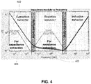
- Figure 4 illustrates evolution of impedance 300 of the capacitor 206 depending on the frequency, according to some embodiments of the invention.
- the capacitance C of the capacitor 206 can be calculated. Indeed, at low frequencies, the capacitor 206 has a capacitive behavior and thus the low frequencies band-pass filter 401 allows the estimation of the capacitance value C of the capacitor 206.
- the low frequencies band-pass filter 401 may exclude frequencies above 1 kHz, in particular above 2 kHz. This is given as illustrative purposes and do not restrict the scope of the invention.
- the low frequencies band-pass filtering can be a band-pass filtering centered around a low frequency, such as 120 Hz for example.
- the ESR of the capacitor 206 can be estimated. Indeed, at middle frequencies, the capacitor 206 has a resistive behavior and thus the band-pass filter allows the estimation of the ESR of the capacitor. As shown in Figure 4 , the middle frequencies band-pass filter may only allow frequencies between 5 kHz and 800 kHz. This is given for illustrative purposes and does not restrict the scope of the invention.
- the band-pass filters (at low frequencies and mid-frequencies) can be applied to the ripple current and to the measured voltage separately, and the impedance can be subsequently calculated based on the filtered ripple current and the filtered voltage.
- a ripple current signal and a measured voltage signal are filtered and then the filtered signals may be processed to calculate a Root Mean Square, RMS, value for each signal or to obtain an image of the effective value such as the peak value of each of the filtered signals or the average value over one half cycle (positive for example) of each of the filtered signals. 1 ⁇ 2 ⁇ f .
- C corresponds to the ratio of the RMS values or of the images when filtered by the first filter and
- ESR corresponds to the ratio of the RMS values or of the images when filtered by the second filter.
- a low-pass filter can also be applied to the measured voltage signal to extract a DC voltage value UDC.
- the filters can be digital filters that are stored in the memory 203 or may be an electronic circuit of the device 200.
- RMS values are calculated because the current running through the capacitor 206 is alternating.
- the temperature T may be a core temperature T c,k determined based on the temperature measurement performed at iteration k, as explained hereafter.
- k is equal to 7 and the environment measurements of line 7 have been acquired at step 301 and filtered at step 302, the preceding lines 1 to 6 having been acquired at previous iterations.
- environment measurements are acquired at regular time intervals, such as every 5000 hours, or are acquired more frequently (or continuously) and then weighted and averaged to obtain a single value for each time interval between two iterations.
- the low frequencies band-pass filtering is such that it enables to calculate C and the middle frequencies band-pass filtering is such that it enables to calculate ESR. Specific values are given hereafter, for illustrative purposes only. Low frequencies band-pass filtering may be performed around 120 Hz and middle frequencies band-pass filtering may be performed around 15 kHz. Alternatively, low frequencies band-pass filtering can be performed at 300 Hz and the middle frequencies band-pass filtering may be performed at 4 kHz. However, as it can be observed in Figure 4 , ESR and C cannot be obtained directly with these filtering values, as 300 Hz and 4 kHz correspond to frequencies from mixed behaviors (both capacitive and resistive behaviors). However, ESR and C can be estimated by using a system of two equations with two unknown parameters (ESR and C). No restriction is attached to the system of equations, which may express the impedance Z filtered separately by two different filters, based on C and ESR.
- the method according to some embodiments of the invention further comprises a step 303 of obtaining parameters related to the version of the capacitor.
- Some of the parameters can be noted ⁇ j with j varying between 1 and n, n being an integer equal or greater than 1.
- Other parameters such as R th , E a , Tmax, U 0 , I RMS0 , ⁇ 1..3 may also be obtained at step 303.
- R th is the thermal resistance of the capacitor.
- E a is the activation energy of the capacitor.
- Uo is the maximum value of voltage allowable for the capacitor and I RMS0 is the maximum RMS value of current allowable for the capacitor.
- Step 303 can be performed only once for a given capacitor and does not need to be iterated as for the other steps.
- the parameters can be obtained directly from a manufacturer data sheet or can be obtained during a preliminary phase. For example, during the preliminary phase, the parameters can be calculated over a test period in a laboratory for example.
- the ⁇ j values are constants enabling to adjust ESR and C values based on the ambient or core temperature as explained hereafter.
- the values ⁇ j can be obtained at step 303:
- the values ESR k and C k are deduced from the impedance values obtained from the two filters, as explained above.
- a first adjustment is performed on the values ESR k and C k and on the previous values of ESR i and C i , for i varying between 1 and k-1.
- the first adjustment is only applied to the values ESR k and C k and adjusted values of ESR i and C i , for i varying between 1 and k-1, have been previously stored in the memory 203.
- the same principle applies to the second adjustment at step 306.
- the first adjustment can be a measurement adjustment (meaning that the values of ESR and C calculated based on the environment measurements are adjusted). This enables to adjust the measurements performed at different times and different conditions, to similar predetermined conditions (such as temperature conditions for example).
- the values ESR i and C i , i varying between 1 and k are temperature dependent and the core temperature of the capacitors varies depending on some of the environment measurements, such as the ambient temperature T amb,k and/or the ripple current i C,k .
- T c,k is the core temperature, which can be derived from the measured ambient temperature T amb .
- ESR k I RMS,k is the RMS value calculated based on the ripple current signal i C,k measured or determined for iteration k and R th is the thermal resistance of the capacitor 206.
- Figure 5 represents the first adjustment of the values ESR i and C i for i varying between 1 and k (k is equal to 7 in the above example) on a graph representing the values ESR and C depending on time.
- the values ESR i and C i are adjusted to a reference temperature corresponding to a maximum temperature.
- the maximum temperature can be obtained from the manufacturer data sheet.
- the reference temperature can be set to any temperature value, such as 25°C for example.
- the constants ⁇ j discussed above depends on the reference temperature.
- the values ESR i are referenced 500 and are adjusted to obtain the adjusted values ESR i,adjusted 501, for example based on the formula given above.
- the values C i are referenced 502 and are adjusted to obtain the adjusted values C i,adjusted 503, for example based on the formula given above (in this example the reference temperature is the maximum temperature value).
- a second adjustment is applied to the adjusted values ESR k,adjusted and C k,adjusted .
- the second adjustment corresponds to a time compression.
- the first adjustment may correspond to the time compression and the second adjustment may correspond to the measurement adjustment (the adjustment of the values ESR and C).
- the reference temperature T 0 for the first and second adjustments may be different.
- the reference temperature T 0 for the second adjustment (time compression) is preferably a maximum rated temperature, even when the reference temperature for the measurement adjustment is a temperature such as 20°C or 25°C.
- reference values ⁇ T 0 , I RMS,0 ESR 0 and V 0 which are preferably maximum rated values for the second adjustment. This allows to have a time scale, which is as compressed as possible.
- the environment conditions are maintained between two iterations: the conditions between k-1 and k are therefore corresponding to the core temperature T c,k-1 (or the ambient temperature T x,k-1 measured at instant k-1), the ripple current i c,k-1 (for example as such, or filtered by the low-frequencies band-pass filter) and/or the applied voltage u k-1 .
- the temperature can be continuously measured between iterations k-1 and k (or at a given frequency, greater than the frequency of iterations k), and an average temperature can be used as environment conditions.
- the following factor K T is calculated for each measurement instant (possibly several times per iteration) and then an average value K T,i can be calculated for iteration i.
- This principle can be extended to the applied voltage and the ripple current or to their corresponding factors K I,i , and K V,i .
- index "0" refers to reference (extreme for example) environment conditions whereas "x" refers to actual environment conditions.
- Figure 6 represents the second adjustment of ESR i,adjusted and C i,adjusted as obtained after step 306 described above, for i varying between 1 and k (k is equal to 7 in the above example) on a graph representing the values ESR and C depending on time, thereby obtaining normalized values ESR i,adjusted,norm and C i,adjusted,norm .
- the values ESR i,adjusted and C i,adjusted are timely adjusted to a common time reference.
- the values ESR i,Tmax are referenced 600 and are adjusted to obtain the normalized values ESR i,adjusted,norm 601, for example based on the formula given above.
- the values C i,adjusted are referenced 602 and are adjusted to obtain the normalized values C i,adjusted,norm 603, for example based on the formula given above.
- evolution models of ESR and C are built based on the adjusted values ESR i,adjusted,norm and C i,adjusted,norm .
- No restriction is attached to the way the evolution models are built.
- an identification may involve a least square criterion.
- the model can be determined such that the differences between the model and the adjusted values ESR i,adjusted,norm and C i,adjusted,norm are minimum according to the least square criterion.
- the models may be built by updating models built at the previous iteration k-1 or may be calculated based on all the measurements acquired (and optionally adjusted) between iterations 1 and k.
- ESR model (t) ⁇ 1 + ⁇ 2 e ⁇ 3 t
- the coefficients ⁇ 1 , ⁇ 2 , ⁇ 3 , ⁇ 4 and ⁇ 5 are therefore calculated and updated at each new iteration k. Therefore, the evolution models (or ageing models) may be updated at each iteration, thereby becoming more and more accurate. The larger k, the more accurate are the evolution models. Alternatively, the models are only calculated once a minimum index k min is reached. For the previous iterations 1 to k min -1, the measurements or adjusted values are stored for being processed ultimately.
- the ESR and C curves can be extrapolated beyond the times corresponding to the iterations 1 to k, at step 308.
- the method may further comprise a step 309 of estimation of RUL values.
- a criterion or several criteria, can be fixed to determine the time corresponding to the end of life of the capacitor 206.
- a criterion can for example be that:
- the RUL values can then be computed by calculating the difference between the estimated end of life (compressed or at extreme conditions) and the compressed time of the current iteration k.
- “Compressed time” refers to the time of the iteration k, as compressed in Figure 6 .
- FIG. 8 there is shown the curve 800 of the ESR evolution model and the curve 803 of the C evolution model. Thresholds 801 and 804 are represented as explained above (double of the initial ESR value and 80% of the initial C value).
- RUL ESR,k 802 and RUL C,k 805 can then be calculated (they correspond to the differences mentioned above).
- the capacitor RUL can then be calculated at step 310 based on the RUL values RUL ESR,k 802 and RUL C,k 805. For example, the minimum value among the RUL values RUL ESR,k 802 and RUL C,K 805 may be selected as the capacitor RUL. Alternatively, an average of the RUL values RUL ESR,k 802 and RUL C,k 805 can be calculated as the capacitor RUL. Other calculations may be applied to the RUL values RUL ESR,k 802 and RUL C,k 805 to determine the capacitor RUL.
- the capacitor RUL, noted RUL 0 , (or RUL 0,k because it is determined for iteration k) is obtained for such reference environment conditions.
- an output is issued based on the capacitor RUL.
- the output can be a state of health value, which is transmitted to a remote entity to be displayed to an operator, or which is displayed on the device or which is used to be compared to a threshold to issue an alarm based on the comparison.
- the state of health can be calculated as:
- a ratio is preferable as the capacitor RUL has been determined for given reference environment conditions.
- An alarm can be issued at step 310 when the state of health is below a predefined alarm threshold, such as 10% or 5% for example.
- the reference conditions may be set by the user of the device 200 via the user interface 209.
- the user may also set the alarm thresholds and may choose which value is to be output at step 311, among a set of several possible values (may for example choose between the two possible ratios mentioned above).
- a step 312 of adjusting the capacitor RUL from reference environment conditions to actual environment conditions may optionally be performed before performing step 311. Indeed, the capacitor RUL calculated at step 310 has been calculated for reference environment conditions and is not representative of the actual environment conditions to which the capacitor is exposed.
- step 306 The same principle as the one used in step 306 for compressing time may be used.
- the effect of each environment condition may be considered (ambient temperature, ripple current and applied voltage).
- RUL x RUL 0 . K T . K I . K V ;
- K T,k , K I,k and K V,k (the values for the last iteration k) can be used as K T , K I and Kv.
- RUL x represents the capacitor value at actual conditions. This value can be used instead of RULo at step 310. RULX can be directly output (instead of indicating a ratio) while indicating that this value corresponds to current conditions.
- Figure 9 is a flowchart showing operations to perform step 303 detailed above, according to some embodiments of the invention.
- the following operations can be performed during a given period, such as a one-day period, which is short enough so that time does not influence the parameters ESR and C during that period.
- the period can therefore be comprised between several hours and several days (maximum one week for example).
- the capacitor 206 is under a given temperature T (for example a core temperature).
- T for example a core temperature. This temperature can be controlled or can depend on the state of normal operation, as explained above.
- ESR and C are calculated as described above, and stored in association with the given temperature.
- Steps 900 and 901 are repeated for different temperature values.
- a reference temperature is defined (such as 20°C, 25°C, or a maximum temperature for example).
- 20°C is defined as reference temperature and is noted T20.
- the ESR and C values are normalized by being respectively divided by ESR T20 and C T20 , which are ESR and T values for the reference temperature.
- a least square method may be used to determine the values ⁇ j .
Landscapes
- Engineering & Computer Science (AREA)
- Physics & Mathematics (AREA)
- General Physics & Mathematics (AREA)
- Power Engineering (AREA)
- Environmental & Geological Engineering (AREA)
- Testing Electric Properties And Detecting Electric Faults (AREA)
- Measurement Of Resistance Or Impedance (AREA)
Abstract
- repeating for several iterations 1 to k, k being an integer greater than 1:
acquiring (301) environment measurements that are representative of the environment of the capacitor at a current iteration;
- based on previous environment measurements acquired at previous iterations 1 to k-1 before the current iteration, and on the received environment measurements at iteration k, calculating (307) at least one aging model;
- based on the at least one calculated aging model, determining (308-311) the value representative of the RUL of the capacitor
Description
- The present invention relates to the estimation of the remaining useful life of capacitors, and in particular, while not exclusively, of electrolytic capacitors.
- Capacitors are well known devices that are able to store electric energy by accumulating positive and negative charges in anodes and cathodes separated by a dielectric component.
- Electrolytic capacitors are used in power converters such as electric motor drives and Uninterruptible Power System, UPS.
- Electrolytic capacitors are one of the most critical electronic components. A high number of the faults in the static converters are due to electrolytic capacitors, as explained in the documents:
- A. Lahyani, P. Venet, G. Grellet, & P.J. Viverge, Failure prediction of electrolytic capacitors during operation of a switch-mode power supply. IEEE Transactions on power electronics, 1998, 13(6), 1199-1207;
- U.S. of A.D. of Defense, " Military Handbook : Reliability Prediction of Electronic Equipment: MIL-HDBK-217F: 2 December 1991". Department of defense, 1991;
- S. Yang, A. Bryant, P. Mawby, D. Xiang, and P. Tavner, "An industry-based survey of reliability in power electronic converters", in 2009 IEEE Energy Conversion Congress and Exposition, 2009, p. 3151-3157.
- In some power converter applications, it is recommended to replace electrolytic capacitors periodically to avoid an unscheduled stop of the whole power converter product due to a failure in the electrolytic capacitor.
- In UPS products such as some Schneider Electric Galaxy series, it is recommended to replace electrolytic capacitors every five years to avoid an unscheduled stop of the whole UPS product due to a failure in the electrolytic capacitor.
- However, in practice, many capacitors are replaced well before their remaining useful life is expired.
- There is therefore a need to have methods and tools that allow monitoring of environment conditions and/or predicting of the remaining useful life RUL of a capacitor, so as to plan the maintenance on time and warn an operator/user when a capacitor needs to be changed.
- A real capacitor can be seen as equivalent to a resistance, named Equivalent Series Resistance, ESR, in series with a capacitance, named Capacitance C.
- The prior art solutions then propose to evaluate the RUL based on ESR and C, as for example detailed in:
- P. Venet, H. Darnand and G. Grellet, "Detection of faults of filter capacitors in a converter. Application to predictive maintenance", in Proceedings of Intelec 93 : 15th International Telecommunications Energy Conference, 1993, vol. 2, p. 229-234 vol.2;
- P. Venet, F. Perisse, G. Grellet, & G. Rojat. Condensateur intelligent. Demande de brevet frangaise
FR 99 10 292, 1999 - K.-W. Lee, M. Kim, J. Yoon, S. B. Lee, and J.-Y. Yoo, "Condition monitoring of DC-link electrolytic capacitors in adjustable-speed drives", IEEE Trans. Ind. Appl., vol. 44, n°5, p. 1606-1613, 2008;
- K. Abdennadher, P. Venet, G. Rojat, J.-M. Retif and C. Rosset, "A real-time predictive-maintenance system of aluminum electrolytic capacitors used in uninterrupted power supplies", IEEE Trans. Ind. Appl., vol. 46, n°4, p. 1644-1652, 2010.
- In prior art solutions, RUL of capacitors is estimated by building, in a preliminary phase, an ageing model for each capacitor version. The ageing model is constructed offline and requires other than time (several months), many measurements, dedicated equipment, many computations and hardware components, which makes this solution complicated, expensive and unsuitable for industrial application.
- When a new version of a capacitor is introduced, the aging model for this capacitor needs to be constructed again to be able to estimate the RUL.
-
Figure 1 illustrates a method of estimating a RUL of a capacitor according to the prior art. - The method comprises a
preliminary phase 100 of calculating/constructing an aging model. -
Preliminary phase 100 comprises the following steps: - based on specific values such as a maximum temperature value and a maximum voltage value of the capacitor, accelerated aging tests are performed at
step 101 on the capacitor to determine the evolution of the ESR and C values over time; - capacitor parameters are obtained at
step 102. These parameters are specific to the capacitor version; - based on the ESR and C values and on the capacitor parameters, an ESR aging model and a C aging model are constructed at
step 103. Based on these models, and based on a current ESR or C value, a RUL can be directly determined; - the constructed ESR and C models are stored at
step 104 in a storage in association with the version of the capacitor. Therefore,steps 101 to 104 need to be performed for each capacitor version, which is long and costly. - A
current phase 110 of estimation of a RUL for a capacitor of a given version, comprises the following steps according to the prior art: - at
step 111, based on current measurement of values, current values of ESR and C are determined atstep 112; - at
step 112, ESR and C models corresponding to the capacitor version are retrieved from the storage; - at
step 113, the current ESR and C values are respectively compared with the retrieved models to extract two RUL values; - at
step 114, a capacitor RUL is determined based on the two extracted RUL values. - Therefore, determination of a capacitor RUL lacks flexibility as models need to be calculated and stored for each capacitor version.
- There is a need to determine the RUL of a capacitor, which requires less computation capabilities and which is more flexible than the solutions of the prior art.
- It is an object of the invention to alleviate at least some of the disadvantages mentioned above.
- A first aspect of the invention concerns a method for determining a value representative of the remaining useful life, RUL, of a capacitor, the method comprising the following operations:
- repeating for several iterations 1 to k, k being an integer greater than 1:
acquiring environment measurements that are representative of the environment of the capacitor at a current iteration; - based on previous environment measurements acquired at previous iterations 1 to k-1 before the current iteration k, and on the received environment measurements at iteration k, calculating at least one aging model;
- based on the at least one calculated aging model, determining the value representative of the RUL of the capacitor.
- According to some embodiments, the environment measurements may comprise:
- a temperature measurement in the vicinity of the capacitor;
- a voltage measurement representative of a value of the voltage at terminals of the capacitor; and/or
- a current measurement representative of a value of the current flowing through the capacitor.
- In complement, for each iteration, a core temperature of the capacitor may be determined based on a measured ambient temperature in the vicinity of the capacitor, and the aging model may be calculated based on the core temperature, based on the current value and/or based on the voltage value.
- According to some embodiments, the method may further comprise the estimation of an Equivalent Series Resistance, ESRi, value and/or of a capacitance Ci value, for each iteration i, i being comprised between 1 and k, and at least one aging model may represent the evolution of the ESR value of the capacitor for iterations 1 to k and/or the evolution of the C value of the capacitor for iterations 1 to k.
- In complement, a first aging model may represent the evolution of an ESR value of the capacitor for iterations 1 to k and a second aging model represents the evolution of the C value of the capacitor for iterations 1 to k.
- In complement, the ESR value and/or the C value may be obtained by filtering the value of the voltage at the terminals of the capacitor and the value of the current flowing through the capacitor.
- In complement, the C value may be obtained by applying a band-pass filter at low frequencies and/or the ESR value is obtained by applying a band-pass filter at middle frequencies.
- In complement, the low frequencies may include 120 Hz and the middle frequencies may include 15 kHz; or the low frequencies may include 300 Hz and the middle frequencies may include 4 kHz.
- According to some embodiments, the aging model may comprise at least one impedance value and a time for each iteration, the impedance value being determined based on the current value and on the voltage value, and the impedance value, for each iteration i, is adjusted based on a temperature value corresponding to iteration i and based on reference conditions.
- In complement, the temperature value may be a core temperature of the capacitor Tc,i, calculated for each iteration i based on a temperature measurement Tamb,i representative of the ambient temperature in the vicinity of the capacitor.
- In complement, the core temperature Tc,i may be calculated as follows :

- wherein IRMS is a Root Mean Square value of the current flowing through the capacitor for iteration i;
- Rth is a thermal resistance of the capacitor; and
- ESRi is an Equivalent Series Resistance value of the capacitor for iteration i.
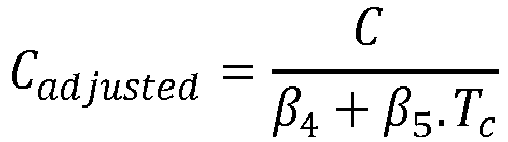
- In complement, or alternatively, for each iteration i, the impedance value may comprise the ESRi value and/or the Ci value, and the ESRi value and/or the Ci value may be adjusted according to core temperature Tc,i to determine adjusted value ESRi,adjusted and/or Ci,adjusted based on for example:


- In complement, the method may further comprise a preliminary phase of determining β1, β2, β3, β4 and β5 by varying temperature conditions during a test period and performing current and voltage measurements during the test period.
- According to some embodiments, the aging model may comprise at least one impedance value and a time for each iteration, the impedance value being determined based on the current value and on the voltage value, and the time, for each iteration i, may be adjusted based on a temperature value, a current value and/or a voltage corresponding to iteration i and based on reference conditions.
- In complement, the time for each iteration i may be adjusted based on a combination of one or several of the following factors KT,i , KI,i , KV and KTI,i :


- According to some embodiments, the at least one aging model may be updated at each iteration i based on the previous ageing model determined at iteration i-1 and based on the environment measurements acquired at iteration i, and the value representative of the RUL may be determined after each iteration i, i being comprised between 1 and k.
- According to some embodiments, the value representative of the RUL of the capacitor may be determined by extrapolating values of the at least one aging model and by comparing the extrapolated values with at least one predetermined threshold.
- According to some embodiments, the value representative of the RUL of the capacitor may be:
- a ratio between the calculated RUL of the capacitor based on the aging model, and an estimated end of life based on the aging model; or
- a ratio between the calculated RUL of the capacitor based on the aging model, and a predetermined end of life.
- According to some embodiments, the method may further comprise:
- comparing the value representative of the RUL with a predetermined threshold; and
- issuing an alarm based on the comparison.
- According to some embodiments, the RUL of the capacitor may be determined for reference conditions and the value representative of the RUL:
- is directly derived from the RUL of the capacitor; or
- is derived from an actual RUL, noted RULX obtained by adjusting the RUL of the capacitor, noted RUL0, to actual conditions.
- In complement, the reference conditions may be set by a user.
- A second aspect of the invention concerns a non-transitory computer readable storage medium, with a computer program stored thereon, said computer program comprising instructions for, when executed by a processor, carrying out the steps of a method according to the first aspect of the invention.
- A third aspect of the invention concerns a device for determining a value representative of the remaining useful life, RUL, of a capacitor, the device comprising a memory and a processor configured for:
- repeating for several iterations 1 to k, k being an integer greater than 1:
acquiring, via at least one sensor or at least one communication interface, environment measurements that are representative of the environment of the capacitor at a current iteration; - based on previous environment measurements acquired at previous iterations 1 to k-1 before the current iteration k, and on the received environment measurements at iteration k, calculating the at least one aging model;
- based on the at least one updated aging model, determining the value representative of the RUL of the capacitor.
- Further objects, aspects, effects and details of the invention are described in the following detailed description of number of exemplary embodiments, with reference to the drawings.
- By way of example only, the embodiments of the present disclosure will be described with reference to the accompanying drawing, wherein:
-
FIG. 1 illustrates a method according to the prior art; -
FIG. 2 represents a device according to some embodiments of the invention; -
FIG. 3 is a flowchart showing the steps of a method according some embodiments of the invention; -
FIG. 4 is a diagram illustrating application of two filters to environment measurements acquired from the capacitor environment, according to some embodiments of the invention; -
FIG. 5 illustrates adjustments of characteristic values ESR and C based on predetermined environment conditions, according to some embodiments of the invention; -
FIG. 6 illustrates time-based adjustments on predetermined environment conditions, according to some embodiments of the invention; -
FIG. 7 illustrates calculations of models for characteristic values ESR and C according to some embodiments of the invention; and -
FIG. 8 illustrates calculations of RUL values according to some embodiments of the invention; -
FIG. 9 is a flowchart showing operations to perform one of the steps illustrated onFIG. 3 . - Referring to
Figure 2 , there is shown adevice 200 for estimating RUL of a capacitor 206 (hereafter "capacitor RUL") according to some embodiments of the invention. Thedevice 200 can be integrated in a system comprising a capacitor. Thecapacitor 206 can be integrated in alarger equipment 207 such as a converter for example. No restriction is attached to theequipment 207, which can be any equipment integrating a capacitor. - The
device 200 may comprise at least onesensor 201 that is configured for acquiring environment measures representative of the environment of thecapacitor 206 at a current time. - Alternatively, and preferably, the device may comprise a
communication interface 204 that is configured for communicating with one or severalremote sensors 208 located in the vicinity of thecapacitor 206, for example inside theequipment 207. For example, in most of converters comprising capacitors, an ambient temperature sensor is natively integrated. Else, one can be added at a low cost. It is to be noted that theexternal sensors 208 may be located outside of theequipment 207. -
Sensors capacitor 206. - Therefore, environment measurements can be acquired by the
device 200 via thesensor 201 and/or via thecommunication interface 204. - The
sensors 201 and/or 208 may be temperature sensors, current sensors and/or voltage sensors for example. However, no restriction is attached to the type of sensors and these examples are given for illustrative purposes. The ripple current ic of thecapacitor 206 can be deduced by an algorithm based on input and output currents of the converter and switch states. Alternatively,sensor 201 and/or 208 directly measuring the ripple current iC may be used. - The
device 200 may further comprise auser interface 209 for interacting with a user. In particular, theuser interface 209 may allow a user to set reference conditions or to select a value representative of the RUL of the capacitor among several possible values. - The
device 200 may further comprise aprocessor 202 and amemory 203, which are configured for performing the steps of the method illustrated inFigure 3 . -
Figure 3 is a flowchart showing the steps of a method according to some embodiments of the invention. The steps offigure 3 are iterated according to the invention. In what follows, there is referred to an iteration k, k being an integer greater than or equal to 1. No restriction is attached to the time duration between consecutive iterations. These time durations can be fixed (environment measurements performed at a given frequency, such as every 1000 hours for example) or may vary (triggered by an event detection for example). - At
step 301, thedevice 200 acquires (measures viasensors 201 or receives fromexternal sensors 208 via the communication interface 204) environment measures representative of the environment of thecapacitor 207 at a current time. The environment measurements may include environment features such as an ambient temperature around thecapacitor 206, a voltage at terminals of thecapacitor 206 or at terminals of theequipment 207, and a current flowing through the capacitor 206 (named "ripple current hereafter) or through theequipment 207. When the current running through, or the voltage at, the equipment is measured, the ripple current or the capacitor voltage can be deduced from the measured value(s) based on the architecture of theequipment 207 integrating thecapacitor 206. - Preferably, several measurements of a same environment feature are obtained at
step 301. For example, several variations of the capacitor voltage and/or ripple current over a given period is obtained. The temperature, which is a less variable environment feature, may be represented by a single value (an instantaneous value or an average value over the period for example). No restriction is attached to the frequency of measurements and to the number of measurements performed for each iteration of the method according to the invention. For example, the measurements can be performed at a regular frequency, or continuously, between two iterations k and k+1. For illustrative purposes, environment measures can be acquired every 10 seconds or continuous signals can be acquired as environment measures. - At
step 302, at least some of the environment measures may be filtered by at least one filter. For example, an impedance Z corresponding to the ratio between the capacitor voltage and the ripple current may be filtered. Alternatively, and preferably, as it is easier to implement, the capacitor voltage and the ripple current may be filtered separately, and the impedance Z may be calculated subsequently based on the filtered values. -
Figure 4 illustrates evolution of impedance 300 of thecapacitor 206 depending on the frequency, according to some embodiments of the invention. - By applying a band-
pass filter 401 in low frequencies (for example between 0 and 1kHz or 2kHz, more generally less than several kHz) to the impedance Z, the capacitance C of thecapacitor 206 can be calculated. Indeed, at low frequencies, thecapacitor 206 has a capacitive behavior and thus the low frequencies band-pass filter 401 allows the estimation of the capacitance value C of thecapacitor 206. As shown inFigure 4 , the low frequencies band-pass filter 401 may exclude frequencies above 1 kHz, in particular above 2 kHz. This is given as illustrative purposes and do not restrict the scope of the invention. The low frequencies band-pass filtering can be a band-pass filtering centered around a low frequency, such as 120 Hz for example. - By applying a middle frequencies band-pass filter to the impedance Z, the ESR of the
capacitor 206 can be estimated. Indeed, at middle frequencies, thecapacitor 206 has a resistive behavior and thus the band-pass filter allows the estimation of the ESR of the capacitor. As shown inFigure 4 , the middle frequencies band-pass filter may only allow frequencies between 5 kHz and 800 kHz. This is given for illustrative purposes and does not restrict the scope of the invention. - Alternatively, the band-pass filters (at low frequencies and mid-frequencies) can be applied to the ripple current and to the measured voltage separately, and the impedance can be subsequently calculated based on the filtered ripple current and the filtered voltage. In that embodiment, a ripple current signal and a measured voltage signal are filtered and then the filtered signals may be processed to calculate a Root Mean Square, RMS, value for each signal or to obtain an image of the effective value such as the peak value of each of the filtered signals or the average value over one half cycle (positive for exemple) of each of the filtered signals. ½πf.C then corresponds to the ratio of the RMS values or of the images when filtered by the first filter and ESR corresponds to the ratio of the RMS values or of the images when filtered by the second filter.
- A low-pass filter can also be applied to the measured voltage signal to extract a DC voltage value UDC.
- The filters can be digital filters that are stored in the
memory 203 or may be an electronic circuit of thedevice 200. - After filtering the ripple current ic and the voltage u at low and middle frequencies, for iteration k, and calculating the RMS values Urms and Irms, the following table, which is given as an example, can be obtained :

- RMS values are calculated because the current running through the
capacitor 206 is alternating. - In the table, the temperature T may be a core temperature Tc,k determined based on the temperature measurement performed at iteration k, as explained hereafter.
- In that example, k is equal to 7 and the environment measurements of line 7 have been acquired at
step 301 and filtered atstep 302, the preceding lines 1 to 6 having been acquired at previous iterations. According to the above table, environment measurements are acquired at regular time intervals, such as every 5000 hours, or are acquired more frequently (or continuously) and then weighted and averaged to obtain a single value for each time interval between two iterations. - The low frequencies band-pass filtering is such that it enables to calculate C and the middle frequencies band-pass filtering is such that it enables to calculate ESR. Specific values are given hereafter, for illustrative purposes only. Low frequencies band-pass filtering may be performed around 120 Hz and middle frequencies band-pass filtering may be performed around 15 kHz. Alternatively, low frequencies band-pass filtering can be performed at 300 Hz and the middle frequencies band-pass filtering may be performed at 4 kHz. However, as it can be observed in
Figure 4 , ESR and C cannot be obtained directly with these filtering values, as 300 Hz and 4 kHz correspond to frequencies from mixed behaviors (both capacitive and resistive behaviors). However, ESR and C can be estimated by using a system of two equations with two unknown parameters (ESR and C). No restriction is attached to the system of equations, which may express the impedance Z filtered separately by two different filters, based on C and ESR. - Referring back to
Figure 3 , the method according to some embodiments of the invention further comprises astep 303 of obtaining parameters related to the version of the capacitor. Some of the parameters can be noted βj with j varying between 1 and n, n being an integer equal or greater than 1. Other parameters such as Rth, Ea, Tmax, U0, IRMS0, γ1..3 may also be obtained atstep 303. Rth is the thermal resistance of the capacitor. Ea is the activation energy of the capacitor. Uo is the maximum value of voltage allowable for the capacitor and IRMS0 is the maximum RMS value of current allowable for the capacitor. These other parameters can be directly obtained from a manufacturer data sheet. Step 303 can be performed only once for a given capacitor and does not need to be iterated as for the other steps. - The parameters can be obtained directly from a manufacturer data sheet or can be obtained during a preliminary phase. For example, during the preliminary phase, the parameters can be calculated over a test period in a laboratory for example. The βj values are constants enabling to adjust ESR and C values based on the ambient or core temperature as explained hereafter.
- The values βj can be obtained at step 303:
- from a manufacturer data sheet;
- from a training period, such as a one-day training period, during which the value ESRadjusted, Cadjusted described below are considered as fixed for a given core temperature (for example 25°C or a maximum temperature value) and during which ESR, C and core temperature Tc are estimated. The main goal is to obtain the influence of a varying temperature during a day (or more generally a period which is short enough so that aging does not influence the values ESR and C) on the estimated value of ESR an C, so that the values βj can be determined based on the following formula for example:

- This can be performed after commissioning of the
equipment 207 and during normal operation; - from a training period, such as a one-day training period, for example before commissioning of the
equipment 207, the value ESRadjusted, Cadjusted described below are considered as fixed for a given core temperature (for example 25°C or a maximum temperature value) and core temperature Tc is controlled to make it vary. ESR and C are measured for different temperatures so that the values βj can be estimated from the formula above. - At
step 304, the values ESRk and Ck are deduced from the impedance values obtained from the two filters, as explained above. - At step 305, a first adjustment is performed on the values ESRk and Ck and on the previous values of ESRi and Ci, for i varying between 1 and k-1. Alternatively, the first adjustment is only applied to the values ESRk and Ck and adjusted values of ESRi and Ci, for i varying between 1 and k-1, have been previously stored in the
memory 203. The same principle applies to the second adjustment at step 306. - As an example, the first adjustment can be a measurement adjustment (meaning that the values of ESR and C calculated based on the environment measurements are adjusted). This enables to adjust the measurements performed at different times and different conditions, to similar predetermined conditions (such as temperature conditions for example). Indeed, the values ESRi and Ci, i varying between 1 and k, are temperature dependent and the core temperature of the capacitors varies depending on some of the environment measurements, such as the ambient temperature Tamb,k and/or the ripple current iC,k. First adjusted values ESRk,adjusted and Ck,adjusted may be calculated as follows:


- The βk values have been obtained at
step 303 as explained above. Tc,k is the core temperature, which can be derived from the measured ambient temperature Tamb. For example, Tc,k can be calculated as follows :
capacitor 206.Figure 5 represents the first adjustment of the values ESRi and Ci for i varying between 1 and k (k is equal to 7 in the above example) on a graph representing the values ESR and C depending on time. In the example ofFigure 5 , the values ESRi and Ci are adjusted to a reference temperature corresponding to a maximum temperature. The maximum temperature can be obtained from the manufacturer data sheet. Alternatively, the reference temperature can be set to any temperature value, such as 25°C for example. The constants βj discussed above depends on the reference temperature. - The values ESRi are referenced 500 and are adjusted to obtain the adjusted
values ESR i,adjusted 501, for example based on the formula given above. The values Ci are referenced 502 and are adjusted to obtain the adjustedvalues C i,adjusted 503, for example based on the formula given above (in this example the reference temperature is the maximum temperature value). - At step 306, a second adjustment is applied to the adjusted values ESRk,adjusted and Ck,adjusted. In this exemplary embodiment, the second adjustment corresponds to a time compression. It is to be noted that this is given for illustrative purposes and that, alternatively, the first adjustment may correspond to the time compression and the second adjustment may correspond to the measurement adjustment (the adjustment of the values ESR and C). It is to be noted that the reference temperature T0 for the first and second adjustments may be different. For example, the reference temperature T0 for the second adjustment (time compression) is preferably a maximum rated temperature, even when the reference temperature for the measurement adjustment is a temperature such as 20°C or 25°C. This also applies to reference values ΔT 0, IRMS,0 ESR0 and V0, which are preferably maximum rated values for the second adjustment. This allows to have a time scale, which is as compressed as possible.
- It can be considered that the environment conditions are maintained between two iterations: the conditions between k-1 and k are therefore corresponding to the core temperature Tc,k-1 (or the ambient temperature Tx,k-1 measured at instant k-1), the ripple current ic,k-1 (for example as such, or filtered by the low-frequencies band-pass filter) and/or the applied voltage uk-1. Alternatively, the temperature can be continuously measured between iterations k-1 and k (or at a given frequency, greater than the frequency of iterations k), and an average temperature can be used as environment conditions. Alternatively, and preferably, the following factor KT is calculated for each measurement instant (possibly several times per iteration) and then an average value KT,i can be calculated for iteration i. This principle can be extended to the applied voltage and the ripple current or to their corresponding factors KI,i, and KV,i.
- It is proposed for example, to calculate factors KT,i, KI,i, KV,i based on the following formulas:
Based on what the manufacturer gives: - For the temperature factor KT,i:

- For the current factor KI,i :


step 303. It is representative of a maximum temperature variation due to current variation (self-heating) that the capacitor can support without being degraded. ΔT 0 may for example be equal to 10°C. This value is preferably predetermined. - For the voltage factor KV,i :

step 303 and Vx,i is the actual applied operating voltage (the measured voltage) at instant i and n is a predetermined empirical safety factor. n can for example be comprised between 2 and 5. This parameter can be obtained atstep 303, from a manufacturer data sheet or technical note for example. - Once the factors KT,i, KI,i, KV,i are calculated, the compression of time of each interval Δtimex,i between two consecutive iterations i and i+1 (this interval being fixed to 5000 hours in the above example) can be compressed to obtain Δtime 0,i :

- As per the other notations, the index "0" refers to reference (extreme for example) environment conditions whereas "x" refers to actual environment conditions.
- An alternative formula based on the Arrhenius law, which is more accurate than the above manufacturer formula, can be used to determine KT,i.KI,i, which can be noted KTI,i :


-
Figure 6 represents the second adjustment of ESRi,adjusted and Ci,adjusted as obtained after step 306 described above, for i varying between 1 and k (k is equal to 7 in the above example) on a graph representing the values ESR and C depending on time, thereby obtaining normalized values ESRi,adjusted,norm and Ci,adjusted,norm. - The values ESRi,adjusted and Ci,adjusted are timely adjusted to a common time reference. The values ESRi,Tmax are referenced 600 and are adjusted to obtain the normalized
values ESR i,adjusted,norm 601, for example based on the formula given above. The values Ci,adjusted are referenced 602 and are adjusted to obtain the normalizedvalues C i,adjusted,norm 603, for example based on the formula given above. - At a
step 307, evolution models of ESR and C are built based on the adjusted values ESRi,adjusted,norm and Ci,adjusted,norm. No restriction is attached to the way the evolution models are built. For example, an identification may involve a least square criterion. For example, the model can be determined such that the differences between the model and the adjusted values ESRi,adjusted,norm and Ci,adjusted,norm are minimum according to the least square criterion. The models may be built by updating models built at the previous iteration k-1 or may be calculated based on all the measurements acquired (and optionally adjusted) between iterations 1 and k. - As shown in
Figure 7 , the model ESTmodel(t) may be in the predetermined form ESRmodel(t)=α1+ α2e α 3 t and the evolution model Cmodel(t) may be in the predetermined form Cmodel(t)= α4+ α5t. This means that it is assumed that the evolution models have the above forms and that the evolution models are built by determining optimal values of the coefficients α1, α2, α3, α4 and α5. No restriction is attached to the form of the models, which can be different from what is shown inFigure 7 . - The coefficients α1, α2, α3, α4 and α5 are therefore calculated and updated at each new iteration k. Therefore, the evolution models (or ageing models) may be updated at each iteration, thereby becoming more and more accurate. The larger k, the more accurate are the evolution models. Alternatively, the models are only calculated once a minimum index kmin is reached. For the previous iterations 1 to kmin-1, the measurements or adjusted values are stored for being processed ultimately.
- Based on the determined models, the ESR and C curves can be extrapolated beyond the times corresponding to the iterations 1 to k, at
step 308. - After the models have been built at
step 307 and the ESRmodel(t) and Cmodel(t) curves have been extrapolated atstep 308, the method may further comprise astep 309 of estimation of RUL values. To this end, a criterion, or several criteria, can be fixed to determine the time corresponding to the end of life of thecapacitor 206. - A criterion can for example be that:
- the ESR value doubles compared to its initial value; and/or
- the C value decreases by 20% compared to its initial value.
- When a criterion is met, a time corresponding to the end of life of the capacitor according to this criterion can be deduced.
- No restriction is attached to the criteria used for estimating the end of life. For example, threshold values different from those given above may be used.
- The RUL values can then be computed by calculating the difference between the estimated end of life (compressed or at extreme conditions) and the compressed time of the current iteration k. "Compressed time" refers to the time of the iteration k, as compressed in
Figure 6 . - Referring to
Figure 8 , there is shown thecurve 800 of the ESR evolution model and thecurve 803 of the C evolution model.Thresholds - Two RUL values
RUL ESR,k 802 andRUL C,k 805 can then be calculated (they correspond to the differences mentioned above). - The capacitor RUL can then be calculated at
step 310 based on the RUL valuesRUL ESR,k 802 andRUL C,k 805. For example, the minimum value among the RUL valuesRUL ESR,k 802 andRUL C,K 805 may be selected as the capacitor RUL. Alternatively, an average of the RUL valuesRUL ESR,k 802 andRUL C,k 805 can be calculated as the capacitor RUL. Other calculations may be applied to the RUL valuesRUL ESR,k 802 andRUL C,k 805 to determine the capacitor RUL. - Because of steps 305 and 306 of adjustments to reference environment conditions (for example extreme environment conditions), the capacitor RUL, noted RUL0, (or RUL0,k because it is determined for iteration k) is obtained for such reference environment conditions.
- At
step 311, an output is issued based on the capacitor RUL. The output can be a state of health value, which is transmitted to a remote entity to be displayed to an operator, or which is displayed on the device or which is used to be compared to a threshold to issue an alarm based on the comparison. - The state of health can be calculated as:
- a ratio between the capacitor RUL and the end of life estimated as shown in
Figure 8 (time when the ESTmodel(t) curve and/or the Cmodel(t) curve reaches a threshold); - a ratio between the capacitor RUL and a predetermined end of life, such as the end of life given by the manufacturer data sheet.
- A ratio is preferable as the capacitor RUL has been determined for given reference environment conditions.
- An alarm can be issued at
step 310 when the state of health is below a predefined alarm threshold, such as 10% or 5% for example. - The reference conditions may be set by the user of the
device 200 via theuser interface 209. The user may also set the alarm thresholds and may choose which value is to be output atstep 311, among a set of several possible values (may for example choose between the two possible ratios mentioned above). - A step 312 of adjusting the capacitor RUL from reference environment conditions to actual environment conditions may optionally be performed before performing
step 311. Indeed, the capacitor RUL calculated atstep 310 has been calculated for reference environment conditions and is not representative of the actual environment conditions to which the capacitor is exposed. - The same principle as the one used in step 306 for compressing time may be used. To adjust time from reference conditions to actual condition, the effect of each environment condition may be considered (ambient temperature, ripple current and applied voltage).

- For example, KT,k, KI,k and KV,k (the values for the last iteration k) can be used as KT, KI and Kv.
- RULx represents the capacitor value at actual conditions. This value can be used instead of RULo at
step 310. RULX can be directly output (instead of indicating a ratio) while indicating that this value corresponds to current conditions. - According to different embodiments:
-
steps 301 to 312 are repeated for each iteration 1 to k; or -
steps 301 to 306 are repeated for iterations 1 to kmin and the measurements or adjusted values are stored in memory, and steps 301 to 312 may be iterated for the next iterations; or -
steps 301 to 306 are iterated and the measurements or adjusted values are stored in memory, and steps 307 to 312 are performed upon request of the user via the user interface; or -
steps 301 to 306, are iterated and the measurements or adjusted values are stored in memory and steps 307 to 312 are performed once k reaches a predetermined value; or -
steps 301 to 307 are iterated and the latest (updated) versions of the models are stored in memory, and steps 308 to 312 are performed upon request of the user via the user interface; or -
steps 301 to 307 are iterated and the latest (updated) versions of the models are stored in memory, and steps 308 to 312 are performed once k reaches a predetermined value. -
Figure 9 is a flowchart showing operations to performstep 303 detailed above, according to some embodiments of the invention. - In particular, operations to obtain the values βj are represented.
- As explained above, the following operations can be performed during a given period, such as a one-day period, which is short enough so that time does not influence the parameters ESR and C during that period. The period can therefore be comprised between several hours and several days (maximum one week for example).
- At
step 900, thecapacitor 206 is under a given temperature T (for example a core temperature). This temperature can be controlled or can depend on the state of normal operation, as explained above. - At
step 901, ESR and C are calculated as described above, and stored in association with the given temperature. -
Steps - At
step 902, a reference temperature is defined (such as 20°C, 25°C, or a maximum temperature for example). We assume that 20°C is defined as reference temperature and is noted T20. The ESR and C values are normalized by being respectively divided by ESRT20 and CT20, which are ESR and T values for the reference temperature. - At
step 903, the curve


- A least square method may be used to determine the values βj.
- Although the present invention has been described above with reference to specific embodiments, it is not intended to be limited to the specific form set forth herein. Rather, the invention is limited only by the accompanying claims and, other embodiments than the specific above are equally possible within the scope of these appended claims.
- Furthermore, although exemplary embodiments have been described above in some exemplary combination of components and/or functions, it should be appreciated that, alternative embodiments may be provided by different combinations of members and/or functions without departing from the scope of the present disclosure. In addition, it is specifically contemplated that a particular feature described, either individually or as part of an embodiment, can be combined with other individually described features, or parts of other embodiments.
Claims (23)
acquiring (301) environment measurements that are representative of the environment of the capacitor at a current iteration;
wherein the low frequencies include 300 Hz and wherein the middle frequencies include 4 kHz.


acquiring, via at least one sensor or at least one communication interface, environment measurements that are representative of the environment of the capacitor at a current iteration;
Priority Applications (3)
| Application Number | Priority Date | Filing Date | Title |
|---|---|---|---|
| EP19305671.0A EP3745145A1 (en) | 2019-05-28 | 2019-05-28 | Estimation of the remaining useful life of capacitors |
| US16/878,499 US11408944B2 (en) | 2019-05-28 | 2020-05-19 | Estimation of the remaining useful life of capacitors |
| CN202010465950.7A CN112014659B (en) | 2019-05-28 | 2020-05-28 | Estimation of remaining useful life of capacitors |
Applications Claiming Priority (1)
| Application Number | Priority Date | Filing Date | Title |
|---|---|---|---|
| EP19305671.0A EP3745145A1 (en) | 2019-05-28 | 2019-05-28 | Estimation of the remaining useful life of capacitors |
Publications (1)
| Publication Number | Publication Date |
|---|---|
| EP3745145A1 true EP3745145A1 (en) | 2020-12-02 |
Family
ID=67003352
Family Applications (1)
| Application Number | Title | Priority Date | Filing Date |
|---|---|---|---|
| EP19305671.0A Pending EP3745145A1 (en) | 2019-05-28 | 2019-05-28 | Estimation of the remaining useful life of capacitors |
Country Status (3)
| Country | Link |
|---|---|
| US (1) | US11408944B2 (en) |
| EP (1) | EP3745145A1 (en) |
| CN (1) | CN112014659B (en) |
Cited By (2)
| Publication number | Priority date | Publication date | Assignee | Title |
|---|---|---|---|---|
| EP4057016A1 (en) * | 2021-03-11 | 2022-09-14 | Tridonic GmbH & Co. KG | Method for predicting a remaining lifetime of an electrical component of an electrical circuit |
| CN120385876A (en) * | 2025-05-23 | 2025-07-29 | 四川圣融达容阻科技有限公司 | A new energy capacitor automatic capacity detection device and detection method |
Families Citing this family (5)
| Publication number | Priority date | Publication date | Assignee | Title |
|---|---|---|---|---|
| US12222738B2 (en) | 2022-02-01 | 2025-02-11 | Ford Global Technologies, Llc | Method and system for controlling electric drive system according to predicted temperature of DC-link capacitor to prevent overheating |
| US12267989B2 (en) | 2022-02-10 | 2025-04-01 | Ford Global Technologies, Llc | Method and system for controlling electric drive system according to predicted temperature of inverter busbar |
| JPWO2024096055A1 (en) * | 2022-11-04 | 2024-05-10 | ||
| EP4387068A1 (en) * | 2022-12-15 | 2024-06-19 | Schneider Toshiba Inverter Europe SAS | Process for detecting ageing of a dc bus capacitor of a power converter |
| CN117169636B (en) * | 2023-09-28 | 2024-04-23 | 南京星梵电子科技有限公司 | Intelligent high temperature resistant aluminium electrolytic capacitor environment detecting system |
Citations (8)
| Publication number | Priority date | Publication date | Assignee | Title |
|---|---|---|---|---|
| DE102004035723A1 (en) * | 2004-07-23 | 2006-02-16 | Siemens Ag | Residual lifetime determination method for electrolytic capacitor in frequency converter, determines core temperature and power loss to calculate aging speed |
| US20090112493A1 (en) * | 2007-10-30 | 2009-04-30 | Mge Ups Systems | Method and device for predicting electrolytic capacitor defects, converter and uninterruptible power supply equipped with such a device |
| WO2013107497A1 (en) * | 2012-01-16 | 2013-07-25 | Schneider Electric Buildings Llc | Adjustment of a capacitor charge voltage |
| DE102012105198A1 (en) * | 2012-06-15 | 2013-12-19 | Ebm-Papst Mulfingen Gmbh & Co. Kg | Method for monitoring life span and for determining remaining life span of technical component, involves determining remaining life span based on all current life span-calculations since initial operation |
| WO2015183250A1 (en) * | 2014-05-28 | 2015-12-03 | Schneider Electric Buildings Llc | Estimation of the remaining lifetime of a supercapacitor |
| US20160356837A1 (en) * | 2015-06-04 | 2016-12-08 | Fujitsu Limited | Capacitor life diagnosis device, capacitor life diagnosis method, and program |
| EP3109648A1 (en) * | 2015-06-25 | 2016-12-28 | Mitsubishi Electric R&D Centre Europe B.V. | Method and system for on-line monitoring an electrolytic capacitor condition |
| CN106597176A (en) * | 2016-12-30 | 2017-04-26 | 北京金风科创风电设备有限公司 | Method and system for predicting residual life of electrolytic capacitor |
Family Cites Families (6)
| Publication number | Priority date | Publication date | Assignee | Title |
|---|---|---|---|---|
| JP4912405B2 (en) * | 2006-07-31 | 2012-04-11 | 三菱電機株式会社 | Power supply device and sequencer system |
| JP5778377B2 (en) * | 2009-02-18 | 2015-09-16 | Dxアンテナ株式会社 | Life detection device and life detection method |
| US20170336463A1 (en) * | 2016-05-23 | 2017-11-23 | Exxelia Technologies | Method for determining the maximum time when a capacitor should be replaced |
| CN106569066B (en) * | 2016-10-26 | 2019-06-18 | 西安华为技术有限公司 | A kind of method and device detecting the bus capacitor service life |
| DE102017221096A1 (en) * | 2017-11-24 | 2019-05-29 | Ziehl-Abegg Se | Method and evaluation unit for determining the remaining service life of a capacitor and system |
| CN108414856B (en) * | 2018-02-26 | 2020-07-28 | 南方电网科学研究院有限责任公司 | Method and device for life evaluation of sub-module capacitors of modular multilevel converters |
-
2019
- 2019-05-28 EP EP19305671.0A patent/EP3745145A1/en active Pending
-
2020
- 2020-05-19 US US16/878,499 patent/US11408944B2/en active Active
- 2020-05-28 CN CN202010465950.7A patent/CN112014659B/en active Active
Patent Citations (8)
| Publication number | Priority date | Publication date | Assignee | Title |
|---|---|---|---|---|
| DE102004035723A1 (en) * | 2004-07-23 | 2006-02-16 | Siemens Ag | Residual lifetime determination method for electrolytic capacitor in frequency converter, determines core temperature and power loss to calculate aging speed |
| US20090112493A1 (en) * | 2007-10-30 | 2009-04-30 | Mge Ups Systems | Method and device for predicting electrolytic capacitor defects, converter and uninterruptible power supply equipped with such a device |
| WO2013107497A1 (en) * | 2012-01-16 | 2013-07-25 | Schneider Electric Buildings Llc | Adjustment of a capacitor charge voltage |
| DE102012105198A1 (en) * | 2012-06-15 | 2013-12-19 | Ebm-Papst Mulfingen Gmbh & Co. Kg | Method for monitoring life span and for determining remaining life span of technical component, involves determining remaining life span based on all current life span-calculations since initial operation |
| WO2015183250A1 (en) * | 2014-05-28 | 2015-12-03 | Schneider Electric Buildings Llc | Estimation of the remaining lifetime of a supercapacitor |
| US20160356837A1 (en) * | 2015-06-04 | 2016-12-08 | Fujitsu Limited | Capacitor life diagnosis device, capacitor life diagnosis method, and program |
| EP3109648A1 (en) * | 2015-06-25 | 2016-12-28 | Mitsubishi Electric R&D Centre Europe B.V. | Method and system for on-line monitoring an electrolytic capacitor condition |
| CN106597176A (en) * | 2016-12-30 | 2017-04-26 | 北京金风科创风电设备有限公司 | Method and system for predicting residual life of electrolytic capacitor |
Non-Patent Citations (11)
| Title |
|---|
| "U.S. of A.D. of Defense", 1991, DEPARTMENT OF DEFENSE, article "Military Handbook : Reliability Prediction of Electronic Equipment: MIL-HDBK-217F: 2 December 1991" |
| A. LAHYANIP. VENETG. GRELLETP.J. VIVERGE: "Failure prediction of electrolytic capacitors during operation of a switch-mode power supply", IEEE TRANSACTIONS ON POWER ELECTRONICS, vol. 13, no. 6, 1998, pages 1199 - 1207 |
| CHETAN S KULKARNI ET AL: "Prognostics of Power Electronics, methods and validation experiments", AUTOTESTCON, 2012 IEEE, IEEE, 10 September 2012 (2012-09-10), pages 194 - 199, XP032256926, ISBN: 978-1-4673-0698-0, DOI: 10.1109/AUTEST.2012.6334578 * |
| K. ABDENNADHERP. VENETG. ROJATJ.-M. RETIFC. ROSSET: "A real-time predictive-maintenance system of aluminum electrolytic capacitors used in uninterrupted power supplies", IEEE TRANS. IND. APPL., vol. 46, no. 4, 2010, pages 1644 - 1652, XP011313933 |
| K.-W. LEEM. KIMJ. YOONS. B. LEEJ.-Y. YOO: "Condition monitoring of DC-link electrolytic capacitors in adjustable-speed drives", IEEE TRANS. IND. APPL., vol. 44, no. 5, 2008, pages 1606 - 1613 |
| MARKUS A VOGELSBERGER ET AL: "Life-Cycle Monitoring and Voltage-Managing Unit for DC-Link Electrolytic Capacitors in PWM Converters", IEEE TRANSACTIONS ON POWER ELECTRONICS, INSTITUTE OF ELECTRICAL AND ELECTRONICS ENGINEERS, USA, vol. 26, no. 2, 1 February 2011 (2011-02-01), pages 493 - 503, XP011334719, ISSN: 0885-8993, DOI: 10.1109/TPEL.2010.2059713 * |
| P. VENETF. PERISSEG. GRELLETG. ROJAT: "Condensateur intelligent", DEMANDE DE BREVET FRANGAISE FR, vol. 99, no. 10, 1999, pages 292 |
| P. VENETH. DARNANDG. GRELLET: "Detection of faults of filter capacitors in a converter. Application to predictive maintenance", PROCEEDINGS OF INTELEC 93 : 15TH INTERNATIONAL TELECOMMUNICATIONS ENERGY CONFERENCE, vol. 2, 1993, pages 229 - 234, XP000496224 |
| S. YANGA. BRYANTP. MAWBYD. XIANGP. TAVNER: "An industry-based survey of reliability in power electronic converters", 2009 IEEE ENERGY CONVERSION CONGRESS AND EXPOSITION, 2009, pages 3151 - 3157 |
| VENET P ET AL: "Electrolytic capacitor circuits that can signal their own worn-out state have arrived", IEEE INDUSTRY APPLICATIONS MAGAZINE, IEEE SERVICE CENTER, PISCATAWAY, NJ, US, vol. 8, no. 1, 1 January 2002 (2002-01-01), pages 16 - 20, XP011093294, ISSN: 1077-2618, DOI: 10.1109/2943.974353 * |
| WOHLFAHRT THOMAS ET AL: "Supraharmonic disturbances: Lifetime reduction of electronic mass-market equipment by the aging of electrolytic capacitors", 2018 18TH INTERNATIONAL CONFERENCE ON HARMONICS AND QUALITY OF POWER (ICHQP), IEEE, 13 May 2018 (2018-05-13), pages 1 - 6, XP033354896, DOI: 10.1109/ICHQP.2018.8378899 * |
Cited By (4)
| Publication number | Priority date | Publication date | Assignee | Title |
|---|---|---|---|---|
| EP4057016A1 (en) * | 2021-03-11 | 2022-09-14 | Tridonic GmbH & Co. KG | Method for predicting a remaining lifetime of an electrical component of an electrical circuit |
| WO2022189613A1 (en) * | 2021-03-11 | 2022-09-15 | Tridonic Gmbh & Co Kg | Method for predicting a remaining failure or lifetime of an electrical component of an electrical circuit |
| US12339328B2 (en) | 2021-03-11 | 2025-06-24 | Tridonic Gmbh & Co Kg | Method for predicting a remaining failure or lifetime of an electrical component of an electrical circuit |
| CN120385876A (en) * | 2025-05-23 | 2025-07-29 | 四川圣融达容阻科技有限公司 | A new energy capacitor automatic capacity detection device and detection method |
Also Published As
| Publication number | Publication date |
|---|---|
| CN112014659A (en) | 2020-12-01 |
| US11408944B2 (en) | 2022-08-09 |
| US20200379057A1 (en) | 2020-12-03 |
| CN112014659B (en) | 2025-03-21 |
Similar Documents
| Publication | Publication Date | Title |
|---|---|---|
| US11408944B2 (en) | Estimation of the remaining useful life of capacitors | |
| US8918300B2 (en) | Apparatus and method for battery state of charge estimation | |
| Klotz et al. | New approach for the calculation of impedance spectra out of time domain data | |
| JP5349250B2 (en) | Battery model identification method | |
| EP1873541A1 (en) | Enhanced-accuracy battery capacity prediction | |
| EP2778700A2 (en) | Apparatus for predicting state of a battery pack using discrete wavelet transforms | |
| JP2006524332A (en) | Emergency power supply system deterioration diagnosis system | |
| JP5924617B2 (en) | Equivalent circuit synthesis method and apparatus, and circuit diagnostic method | |
| WO2018091904A1 (en) | Determining a state of health of a battery and providing an alert | |
| EP4636421A1 (en) | Battery evaluation device, machine learning device, battery evaluation program, battery evaluation method, machine learning program, and machine learning method | |
| EP3761048B1 (en) | Battery monitoring system | |
| US20120081104A1 (en) | Method for measurement of total harmonic distortion | |
| WO2018172216A1 (en) | Battery energy store | |
| EP3973304A1 (en) | Battery performance assessment method and apparatus | |
| CN111259316A (en) | Method for calculating residual life of capacitor | |
| EP3317683A1 (en) | Energy storage cell impedance measuring apparatus, methods and related systems | |
| US20200166577A1 (en) | Method and Device for Monitoring a Stable Convergence Behavior of a Kalman Filter | |
| Kulkarni et al. | Prognostics of Power Electronics, methods and validation experiments | |
| CN110677056A (en) | Power supply device with electrolytic capacitor | |
| US9857408B2 (en) | Insulation monitoring device | |
| DE102021101693B9 (en) | Method for measuring pulse error detection and method for determining a system leakage capacitance for use in a method for insulation monitoring in an unearthed power supply system | |
| KR20170059741A (en) | System and method for diagnosing dc input capacitor of inverter, and a recording medium having computer readable program for executing the method | |
| JPWO2019239511A1 (en) | Capacitor capacity estimation device, automobile control system, FA system and capacitor capacity estimation method | |
| JP5618575B2 (en) | Storage battery evaluation apparatus and method | |
| FI125602B (en) | Determination of aging of output capacitor in dc to dc converters |
Legal Events
| Date | Code | Title | Description |
|---|---|---|---|
| PUAI | Public reference made under article 153(3) epc to a published international application that has entered the european phase |
Free format text: ORIGINAL CODE: 0009012 |
|
| STAA | Information on the status of an ep patent application or granted ep patent |
Free format text: STATUS: THE APPLICATION HAS BEEN PUBLISHED |
|
| AK | Designated contracting states |
Kind code of ref document: A1 Designated state(s): AL AT BE BG CH CY CZ DE DK EE ES FI FR GB GR HR HU IE IS IT LI LT LU LV MC MK MT NL NO PL PT RO RS SE SI SK SM TR |
|
| AX | Request for extension of the european patent |
Extension state: BA ME |
|
| STAA | Information on the status of an ep patent application or granted ep patent |
Free format text: STATUS: REQUEST FOR EXAMINATION WAS MADE |
|
| 17P | Request for examination filed |
Effective date: 20210602 |
|
| RBV | Designated contracting states (corrected) |
Designated state(s): AL AT BE BG CH CY CZ DE DK EE ES FI FR GB GR HR HU IE IS IT LI LT LU LV MC MK MT NL NO PL PT RO RS SE SI SK SM TR |
|
| STAA | Information on the status of an ep patent application or granted ep patent |
Free format text: STATUS: EXAMINATION IS IN PROGRESS |
|
| 17Q | First examination report despatched |
Effective date: 20231213 |