EP3745073A1 - Loop-type heat pipe - Google Patents
Loop-type heat pipe Download PDFInfo
- Publication number
- EP3745073A1 EP3745073A1 EP20177201.9A EP20177201A EP3745073A1 EP 3745073 A1 EP3745073 A1 EP 3745073A1 EP 20177201 A EP20177201 A EP 20177201A EP 3745073 A1 EP3745073 A1 EP 3745073A1
- Authority
- EP
- European Patent Office
- Prior art keywords
- flow path
- evaporator
- vapor
- pipe
- wall
- Prior art date
- Legal status (The legal status is an assumption and is not a legal conclusion. Google has not performed a legal analysis and makes no representation as to the accuracy of the status listed.)
- Granted
Links
Images




Classifications
-
- F—MECHANICAL ENGINEERING; LIGHTING; HEATING; WEAPONS; BLASTING
- F28—HEAT EXCHANGE IN GENERAL
- F28D—HEAT-EXCHANGE APPARATUS, NOT PROVIDED FOR IN ANOTHER SUBCLASS, IN WHICH THE HEAT-EXCHANGE MEDIA DO NOT COME INTO DIRECT CONTACT
- F28D15/00—Heat-exchange apparatus with the intermediate heat-transfer medium in closed tubes passing into or through the conduit walls ; Heat-exchange apparatus employing intermediate heat-transfer medium or bodies
- F28D15/02—Heat-exchange apparatus with the intermediate heat-transfer medium in closed tubes passing into or through the conduit walls ; Heat-exchange apparatus employing intermediate heat-transfer medium or bodies in which the medium condenses and evaporates, e.g. heat pipes
- F28D15/0266—Heat-exchange apparatus with the intermediate heat-transfer medium in closed tubes passing into or through the conduit walls ; Heat-exchange apparatus employing intermediate heat-transfer medium or bodies in which the medium condenses and evaporates, e.g. heat pipes with separate evaporating and condensing chambers connected by at least one conduit; Loop-type heat pipes; with multiple or common evaporating or condensing chambers
-
- F—MECHANICAL ENGINEERING; LIGHTING; HEATING; WEAPONS; BLASTING
- F28—HEAT EXCHANGE IN GENERAL
- F28D—HEAT-EXCHANGE APPARATUS, NOT PROVIDED FOR IN ANOTHER SUBCLASS, IN WHICH THE HEAT-EXCHANGE MEDIA DO NOT COME INTO DIRECT CONTACT
- F28D15/00—Heat-exchange apparatus with the intermediate heat-transfer medium in closed tubes passing into or through the conduit walls ; Heat-exchange apparatus employing intermediate heat-transfer medium or bodies
- F28D15/02—Heat-exchange apparatus with the intermediate heat-transfer medium in closed tubes passing into or through the conduit walls ; Heat-exchange apparatus employing intermediate heat-transfer medium or bodies in which the medium condenses and evaporates, e.g. heat pipes
- F28D15/0233—Heat-exchange apparatus with the intermediate heat-transfer medium in closed tubes passing into or through the conduit walls ; Heat-exchange apparatus employing intermediate heat-transfer medium or bodies in which the medium condenses and evaporates, e.g. heat pipes the conduits having a particular shape, e.g. non-circular cross-section, annular
-
- F—MECHANICAL ENGINEERING; LIGHTING; HEATING; WEAPONS; BLASTING
- F28—HEAT EXCHANGE IN GENERAL
- F28D—HEAT-EXCHANGE APPARATUS, NOT PROVIDED FOR IN ANOTHER SUBCLASS, IN WHICH THE HEAT-EXCHANGE MEDIA DO NOT COME INTO DIRECT CONTACT
- F28D15/00—Heat-exchange apparatus with the intermediate heat-transfer medium in closed tubes passing into or through the conduit walls ; Heat-exchange apparatus employing intermediate heat-transfer medium or bodies
- F28D15/02—Heat-exchange apparatus with the intermediate heat-transfer medium in closed tubes passing into or through the conduit walls ; Heat-exchange apparatus employing intermediate heat-transfer medium or bodies in which the medium condenses and evaporates, e.g. heat pipes
- F28D15/04—Heat-exchange apparatus with the intermediate heat-transfer medium in closed tubes passing into or through the conduit walls ; Heat-exchange apparatus employing intermediate heat-transfer medium or bodies in which the medium condenses and evaporates, e.g. heat pipes with tubes having a capillary structure
-
- F—MECHANICAL ENGINEERING; LIGHTING; HEATING; WEAPONS; BLASTING
- F28—HEAT EXCHANGE IN GENERAL
- F28D—HEAT-EXCHANGE APPARATUS, NOT PROVIDED FOR IN ANOTHER SUBCLASS, IN WHICH THE HEAT-EXCHANGE MEDIA DO NOT COME INTO DIRECT CONTACT
- F28D15/00—Heat-exchange apparatus with the intermediate heat-transfer medium in closed tubes passing into or through the conduit walls ; Heat-exchange apparatus employing intermediate heat-transfer medium or bodies
- F28D15/02—Heat-exchange apparatus with the intermediate heat-transfer medium in closed tubes passing into or through the conduit walls ; Heat-exchange apparatus employing intermediate heat-transfer medium or bodies in which the medium condenses and evaporates, e.g. heat pipes
- F28D15/04—Heat-exchange apparatus with the intermediate heat-transfer medium in closed tubes passing into or through the conduit walls ; Heat-exchange apparatus employing intermediate heat-transfer medium or bodies in which the medium condenses and evaporates, e.g. heat pipes with tubes having a capillary structure
- F28D15/043—Heat-exchange apparatus with the intermediate heat-transfer medium in closed tubes passing into or through the conduit walls ; Heat-exchange apparatus employing intermediate heat-transfer medium or bodies in which the medium condenses and evaporates, e.g. heat pipes with tubes having a capillary structure forming loops, e.g. capillary pumped loops
-
- F—MECHANICAL ENGINEERING; LIGHTING; HEATING; WEAPONS; BLASTING
- F28—HEAT EXCHANGE IN GENERAL
- F28D—HEAT-EXCHANGE APPARATUS, NOT PROVIDED FOR IN ANOTHER SUBCLASS, IN WHICH THE HEAT-EXCHANGE MEDIA DO NOT COME INTO DIRECT CONTACT
- F28D15/00—Heat-exchange apparatus with the intermediate heat-transfer medium in closed tubes passing into or through the conduit walls ; Heat-exchange apparatus employing intermediate heat-transfer medium or bodies
- F28D15/02—Heat-exchange apparatus with the intermediate heat-transfer medium in closed tubes passing into or through the conduit walls ; Heat-exchange apparatus employing intermediate heat-transfer medium or bodies in which the medium condenses and evaporates, e.g. heat pipes
- F28D15/04—Heat-exchange apparatus with the intermediate heat-transfer medium in closed tubes passing into or through the conduit walls ; Heat-exchange apparatus employing intermediate heat-transfer medium or bodies in which the medium condenses and evaporates, e.g. heat pipes with tubes having a capillary structure
- F28D15/046—Heat-exchange apparatus with the intermediate heat-transfer medium in closed tubes passing into or through the conduit walls ; Heat-exchange apparatus employing intermediate heat-transfer medium or bodies in which the medium condenses and evaporates, e.g. heat pipes with tubes having a capillary structure characterised by the material or the construction of the capillary structure
Definitions
- the present disclosure relates to a loop-type heat pipe.
- a heat pipe configured to transport heat by using a phase change of an operating fluid is suggested (for example, refer to PTL 1).
- the loop-type heat pipe includes an evaporation unit configured to receive heat from a heat generation body and to evaporate a liquid-phase operating fluid and a condensation unit configured to condense the vapor-phase operating fluid by heat radiation. Also, the loop-type heat pipe includes a vapor pipe for causing the operating fluid vaporized in the evaporation unit to flow into the condensation unit, and a liquid pipe for causing the operating fluid condensed in the condensation unit to flow into the evaporation unit.
- the loop-type heat pipe has a loop structure in which the evaporation unit, the vapor pipe, the condensation unit and the liquid pipe are connected in series, and the operating fluid is enclosed therein.
- a loop-type heat pipe comprises:
- a loop-type heat pipe 1 shown in FIG. 1 is accommodated in a mobile-type electronic device 2 such as a smart phone and a tablet terminal, for example.
- the loop-type heat pipe 1 includes an evaporator 11, a vapor pipe 12, a condenser 13, and a liquid pipe 14.
- the evaporator 11 and the condenser 13 are connected by the vapor pipe 12 and the liquid pipe 14.
- the evaporator 11 has a function of vaporizing an operating fluid C to generate vapor Cv.
- the vapor Cv generated in the evaporator 11 is transported to the condenser 13 through the vapor pipe 12.
- the condenser 13 has a function of condensing the vapor Cv of the operating fluid C.
- the condensed operating fluid C is transported to the evaporator 11 through the liquid pipe 14.
- the vapor pipe 12 and the liquid pipe 14 form a loop-shaped flow path through which the operating fluid C or the vapor Cv is caused to flow.
- the vapor pipe 12 is formed as a long pipe body, for example.
- the liquid pipe 14 is formed as a long pipe body, for example.
- the vapor pipe 12 and the liquid pipe 14 have the same size (i.e., a size in the longitudinal direction), for example.
- the length of the vapor pipe 12 and the length of the liquid pipe 14 may be different from each other.
- the length of the vapor pipe 12 may be shorter than the length of the liquid pipe 14.
- the "longitudinal direction" of the evaporator 11, the vapor pipe 12, the condenser 13 and the liquid pipe 14 is a direction in which the operating fluid C or the vapor Cv flows in each member (refer to the arrow in the drawing).
- the evaporator 11 is closely fixed to a heat generation component (not shown).
- the operating fluid C in the evaporator 11 is vaporized by heat generated in the heat generation component, so that the vapor Cv is generated.
- a thermal conductive member (TIM: Thermal Interface Material) may be interposed between the evaporator 11 and the heat generation component.
- the thermal conductive member reduces a contact thermal resistance between the heat generation component and the evaporator 11, thereby implementing smooth heat conduction from the heat generation component to the evaporator 11.
- the vapor pipe 12 has a pair of pipe walls 12w provided on both sides in a width direction orthogonal to the longitudinal direction of the vapor pipe 12, as seen from above, and a flow path 12r provided between the pair of pipe walls 12w, for example.
- the flow path 12r is formed to communicate with an internal space of the evaporator 11.
- the flow path 12r is a part of the loop-shaped flow path.
- the vapor Cv generated in the evaporator 11 is guided to the condenser 13 through the vapor pipe 12.
- the condenser 13 has a heat radiating plate 13p having a large area for heat radiation and a serpentine flow path 13r in the heat radiating plate 13p, for example.
- the flow path 13r is a part of the loop-shaped flow path.
- the vapor Cv guided through the vapor pipe 12 is condensed in the condenser 13. In this way, in the loop-type heat pipe 1, the heat generated in the heat generation component is transferred to the condenser 13 and is radiated in the condenser 13. Thereby, the heat generation component is cooled, so that an increase in temperature of the heat generation component is suppressed.
- the operating fluid C condensed in the condenser 13 is guided to the evaporator 11 through the liquid pipe 14.
- a fluid having a high vapor pressure and a high evaporative latent heat is preferably used as the operating fluid C.
- Such operating fluid C is used, so that it is possible to effectively cool the heat generation component by the evaporative latent heat.
- ammonia, water, Freon, alcohol, acetone and the like may be used, for example.
- a size W1 of the liquid pipe 14 in the width direction orthogonal to the longitudinal direction, as seen from above, is smaller than a size W2 of the evaporator 11 in the width direction orthogonal to the longitudinal direction, as seen from above.
- the evaporator 11 is provided with a porous body 20.
- the porous body 20 has a connection part 21 and a plurality of protrusions 22.
- the connection part 21 is provided on a side in the internal space of the evaporator 11, which is the closest to the liquid pipe 14 (i.e., a side on which the liquid pipe 14 is connected to the evaporator 11), as seen from above, for example.
- the connection part 21 is formed to extend in the width direction (a right and left direction in FIG. 2 ) of the evaporator 11, for example.
- a surface of the connection part 21 on the liquid pipe 14-side is in partial contact with pipe walls 11w of the evaporator 11 and the remaining thereof is in contact with a space S1, for example.
- connection part 21 on the vapor pipe 12-side is partially connected to the protrusions 22 and the remaining thereof is in contact with a space S2.
- Each of the protrusions 22 protrudes from the connection part 21 toward the vapor pipe 12, as seen from above, for example.
- Each of the protrusions 22 is formed to extend in the longitudinal direction of the evaporator 11, for example.
- the plurality of protrusions 22 is provided with predetermined intervals in the width direction of the evaporator 11, as seen from above, for example.
- An end portion of each of the protrusions 22 on the vapor pipe 12-side is spaced from the pipe walls 11w of the evaporator 11. The end portions of the respective protrusions 22 on the vapor pipe 12-side are not connected to each other.
- the porous body 20 of the present embodiment is formed to have a comb shape having the connection part 21 and the plurality of protrusions 22, as seen from above.
- the number of the teeth of a comb of the porous body 20 can be changed as appropriate.
- an area in which the porous body 20 is not provided is formed with a space S2.
- the space S2 is connected to the flow path 12r of the vapor pipe 12.
- the liquid pipe 14 has a pair of pipe walls 14w provided at both ends of the liquid pipe 14 in the width direction, and a porous body 30 and a vapor moving path 40 provided between the pair of pipe walls 14w.
- the porous body 30 is formed to extend from the condenser 13 (refer to FIG. 1 ) to the vicinity of the evaporator 11 in the longitudinal direction of the liquid pipe 14, for example.
- the porous body 30 is configured to guide the operating fluid C condensed in the condenser 13 to the evaporator 11 by a capillary force that is generated in the porous body 30.
- the porous body 30 has a plurality of pores 62z, 63z, 64z and 65z (refer to FIG. 3 ), for example.
- the plurality of pores 62z to 65z functions as the flow path 14r through which the operating fluid C is to flow.
- the flow path 14r is a part of the loop-shaped flow path.
- a surface of the porous body 30 on the evaporator 11-side is in contact with the space S1, for example.
- the space S1 is interposed between the porous body 30 of the liquid pipe 14 and the porous body 20 of the evaporator 11.
- the space S1 between the porous body 20 and the porous body 30 may be omitted. That is, the porous body 20 and the porous body 30 may be directly connected without the space S1.
- the vapor moving path 40 is formed to extend from the evaporator 11 in the longitudinal direction of the liquid pipe 14.
- the vapor moving path 40 is formed to extend from the evaporator 11 to a point on the halfway in the longitudinal direction of the liquid pipe 14, along the longitudinal direction of the liquid pipe 14, for example.
- the vapor moving path 40 is provided in the vicinity of one pipe wall 14w of the pair of pipe walls 14w, for example.
- the vapor moving path 40 is provided in the vicinity of the pipe wall 14w, which configures an inner side of a bent part of the liquid pipe 14, of the pair of pipe walls 14w.
- the vapor moving path 40 has, for example, a partitioning wall 41, a partitioning wall 42, a flow path 43, and a porous part 50.
- the partitioning wall 41 is formed to extend from the internal space of the evaporator 11 to a point on the halfway in the longitudinal direction of the liquid pipe 14, along the longitudinal direction of the liquid pipe 14.
- An end portion 41A of the partitioning wall 41 on the evaporator 11-side is formed to protrude into the internal space of the evaporator 11, for example.
- the end portion 41A of the partitioning wall 41 is formed to protrude into the inside of the porous body 20 of the evaporator 11, for example.
- the end portion 41A of the partitioning wall 41 is formed to protrude into the inside of the connection part 21 of the porous body 20.
- the partitioning wall 42 is formed to extend from an end portion 41B, which is on an opposite side to the end portion 41A of the partitioning wall 41 in the longitudinal direction, to the pipe wall 14w on one side (herein, a lower side in FIG. 2 ) along a width direction of the liquid pipe 14, for example.
- the partitioning wall 42 is formed to connect the end portion 41B of the partitioning wall 41 and the pipe wall 14w.
- the partitioning wall 42 configures one end portion of the vapor moving path 40 in the longitudinal direction.
- One end portion of the vapor moving path 40 in the longitudinal direction is closed by the partitioning wall 42 on the halfway of the liquid pipe 14 in the longitudinal direction.
- the partitioning walls 41 and 42 are formed to partition the flow path 43 of the vapor moving path 40 and the porous body 30 each other.
- the flow path 43 and the porous body 30 are completely separated by the partitioning walls 41 and 42. In other words, the flow path 43 is not communicating with the flow path 14r of the porous body 30.
- the flow path 43 of the vapor moving path 40 is configured by a space surrounded by the partitioning wall 41, the partitioning wall 42 and the pipe wall 14w.
- the flow path 43 is formed to extend over an entire length of the vapor moving path 40 in the longitudinal direction.
- the flow path 43 is separated from the porous body 30 over the entire length of the vapor moving path 40 in the longitudinal direction by the partitioning walls 41 and 42.
- the partitioning walls 41 and 42 and the pipe wall 14w function as a wall part surrounding the flow path 43.
- the flow path 43 is formed so that a cross-sectional area of a cross section obtained by cutting the vapor moving path 40 along a plane orthogonal to the longitudinal direction of the vapor moving path 40 is larger than a cross-sectional area of the flow path 14r of the porous body 30, for example.
- the cross-sectional area of the flow path 43 is formed smaller than a cross-sectional area of the flow path 12r of the vapor pipe 12, for example.
- the porous part 50 is provided, for example.
- the porous part 50 is formed to extend from the vicinity of the evaporator 11 to the partitioning wall 42 along the longitudinal direction of the vapor moving path 40, for example.
- the porous part 50 is configured to guide the operating fluid C condensed in the vapor moving path 40 to the evaporator 11 by a capillary force that is generated in the porous part 50, for example.
- the porous part 50 and the porous body 30 are completed separated by the partitioning walls 41 and 42 over the entire length of the vapor moving path 40 in the longitudinal direction.
- a surface of the porous part 50 on the evaporator 11-side is in contact with the space S1, for example.
- the space S1 is interposed between the porous part 50 and the porous body 20 of the evaporator 11.
- the space S1 between the porous part 50 and the porous body 20 may be omitted. That is, the porous part 50 and the porous body 20 may be directly connected without the space S1.
- FIG. 2 in order to show planar shapes of the porous body 30 and porous part 50 in the liquid pipe 14 and the porous body 20 in the evaporator 11, a metal layer (for example, a metal layer 61 shown in FIG. 3 ) that is the outermost layer of a plurality of metal layers 61 to 66 (which will be described later) is not shown.
- a metal layer for example, a metal layer 61 shown in FIG. 3
- FIG. 3 is a cross-sectional view of the liquid pipe 14 taken along a line 3A-3A in FIG. 2 .
- This cross section is orthogonal to a direction in which the operating fluid C flows in the liquid pipe 14 (a direction denoted with the arrow in FIG. 2 ).
- the liquid pipe 14 has a structure where six layers of metal layers 61 to 66 are stacked, for example.
- the liquid pipe 14 has a structure where the metal layers 62 to 65, which are intermediate metal layers, are stacked between the metal layers 61 and 66 that are a pair of outermost layers.
- the metal layers 61 to 66 are copper layers having high heat conductivity, for example, and are directly bonded to each other by solid-phase bonding (for example, diffusion bonding, press bonding and ultrasonic bonding) and the like. Meanwhile, in FIG. 3 , the metal layers 61 to 66 are distinguished with solid lines for easy understanding.
- the solid-phase bonding is a method of heating and softening bonding targets in a solid state without melting the same, and then pressing, plastically deforming and bonding the bonding targets.
- the metal layers 61 to 66 are not limited to the copper layers and may be formed of stainless steel, aluminum, magnesium alloy and the like. Also, for some of the stacked metal layers 61 to 66, a material different from the other metal layers may be used. A thickness of each of the metal layers 61 to 66 may be set to about 50 ⁇ m to 200 ⁇ m, for example. In the meantime, some of the metal layers 61 to 66 may be formed to have a thickness different from the other metal layers. Also, all the metal layers may be formed to have thicknesses different from each other.
- the evaporator 11, the vapor pipe 12 and the condenser 13 shown in FIG. 1 are respectively formed by stacking six layers of the metal layers 61 to 66, like the liquid pipe 14 shown in FIG. 3 . That is, the loop-type heat pipe 1 shown in FIG. 1 is configured by stacking six layers of the metal layers 61 to 66. In the meantime, the number of stacked metal layers is not limited to six, and may be five layers or less or seven layers or more.
- the liquid pipe 14 of the present embodiment consists of the stacked metal layers 61 to 66, and has the pipe walls 14w, the porous body 30 and the vapor moving path 40 (the partitioning walls 41 and 42, the flow path 43 and the porous part 50).
- the metal layers 61 and 66 of the metal layers 61 to 66 that are the outermost layers are not formed with a hole and a groove.
- the metal layers 61 and 66 function as a wall part (a top part or a bottom part) of the liquid pipe 14.
- the metal layer 62 has a pair of wall parts 62w provided on both ends in a width direction (a right and left direction in FIG. 3 ) orthogonal to the stacking direction of the metal layers 61 to 66, and a wall part 62t provided between the pair of wall parts 62w.
- the metal layer 62 has a porous body 62s provided between the wall part 62w on one side (herein, a right side in FIG. 3 ) and the wall part 62t and a porous part 62e provided between the wall part 62w on the other side (herein, a left side in FIG. 3 ) and the wall part 62t.
- the metal layer 63 has a pair of wall parts 63w provided on both ends in the width direction and a wall part 63t provided between the pair of wall parts 63w.
- the metal layer 63 has a porous body 63s provided between the wall part 63w on one side (herein, a right side in FIG. 3 ) and the wall part 63t and a through-hole 63X formed between the wall part 63w on the other side (herein, a left side in FIG. 3 ) and the wall part 63t and penetrating the metal layer 63 in a thickness direction.
- the metal layer 64 has a pair of wall parts 64w provided on both ends in the width direction and a wall part 64t provided between the pair of wall parts 64w.
- the metal layer 64 has a porous body 64s provided between the wall part 64w on one side (herein, a right side in FIG. 3 ) and the wall part 64t and a through-hole 64X formed between the wall part 64w on the other side (herein, a left side in FIG. 3 ) and the wall part 63t and penetrating the metal layer 64 in the thickness direction.
- the metal layer 65 has a pair of wall parts 65w provided on both ends in the width direction, and a wall part 65t provided between the pair of wall parts 65w.
- the metal layer 65 has a porous body 65s provided between the wall part 65w on one side (herein, a right side in FIG. 3 ) and the wall part 652t and a porous part 65e provided between the wall part 65w on the other side (herein, a left side in FIG. 3 ) and the wall part 65t.
- each pipe wall 14w is described.
- Each pipe wall 14w is configured by the wall parts 62w to 65w of the intermediate metal layers 62 to 65 of the metal layers 61 to 66.
- Each pipe wall 14w is configured by the plurality of sequentially stacked wall parts 62w to 65w.
- the wall parts 62w to 65w of the present embodiment are not formed with a hole and a groove.
- the porous body 30 is configured by the porous bodies 62s to 65s of the intermediate metal layers 62 to 65 of the metal layers 61 to 66.
- the porous body 30 is configured by the plurality of sequentially stacked porous bodies 62s to 65s.
- the porous body 62s is formed with bottomed holes 62u recessed from an upper surface of the metal layer 62 to a substantially central part in the thickness direction and bottomed holes 62d recessed from a lower surface of the metal layer 62 to a substantially central part in the thickness direction.
- An inner wall of each of the bottomed holes 62u and 62d may have a tapered shape that becomes wider from a bottom side (a central part side of the metal layer 62 in the thickness direction) toward an opening side (upper and lower surfaces-side of the metal layer 62).
- the inner wall of each of the bottomed holes 62u and 62d may be formed to extend vertically with respect to the bottom, for example.
- an inner wall surface of each of the bottomed holes 62u and 62d may be formed to have a concave shape of which a cross-sectional shape is a semicircular or semi-elliptical shape (for example, refer to FIG. 8 and the like).
- the "semicircular shape” includes a half circle obtained by bisecting a true circle, and circles of which arcs are longer or shorter than a half circle, for example.
- the "semi-elliptical shape” includes a semi-ellipse obtained by bisecting an ellipse, and ellipses of which arcs are longer or shorter than the semi-ellipse, for example.
- the bottomed holes 62u and 62d may be formed into a shape in which the inner wall continues in an arc shape over the bottom.
- the bottomed holes 62u and 62d are respectively formed in a circular shape, as seen from above, for example.
- a diameter of each of the bottomed holes 62u and 62d may be set to about 100 ⁇ m to 400 ⁇ m, for example.
- the planar shape of each of the bottomed holes 62u and 62d may be any shape such as an elliptical shape, a polygonal shape and the like.
- the bottomed holes 62u and the bottomed holes 62d partially overlap, as seen from above. As shown in FIGS.
- FIG. 4 illustrates an arrangement state of the bottomed holes 62u and 62d, the partial overlapping of the bottomed holes 62u and 62d, and the pores 62z.
- the porous body 62s having the bottomed holes 62u and 62d and the pores 62z configures a part of the porous body 30.
- the porous body 63s is formed with bottomed holes 63u recessed from an upper surface of the metal layer 63 to a substantially central part in the thickness direction and bottomed holes 63d recessed from a lower surface of the metal layer 63 to a substantially central part in the thickness direction.
- the bottomed holes 63u and 63d may have similar shapes to the bottomed holes 62u and 62d of the metal layer 62.
- the bottomed holes 63u and the bottomed holes 63d partially overlap, as seen from above.
- the bottomed holes 63u and the bottomed holes 63d overlap as seen from above, the bottomed holes 63u and the bottomed holes 63d partially communicate with each other, thereby forming pores 63z.
- the porous body 63s having the bottomed holes 63u and 63d and the pores 63z configures a part of the porous body 30.
- the bottomed holes 62d of the metal layer 62 and the bottomed holes 63u of the metal layer 63 are formed in overlapping positions, as seen from above, for example. For this reason, a pore is not formed at an interface between the bottomed hole 62d and the bottomed hole 63u.
- the porous body 64s is formed with bottomed holes 64u recessed from an upper surface of the metal layer 64 to a substantially central part in the thickness direction and bottomed holes 64d recessed from a lower surface of the metal layer 64 to a substantially central part in the thickness direction.
- the bottomed holes 64u and 64d may have similar shapes to the bottomed holes 62u and 62d of the metal layer 62.
- the bottomed holes 64u and the bottomed holes 64d partially overlap, as seen from above. In portions in which the bottomed holes 64u and the bottomed holes 64d overlap as seen from above, the bottomed holes 64u and the bottomed holes 64d partially communicate with each other, thereby forming pores 64z.
- the porous body 64s having the bottomed holes 64u and 64d and the pores 64z configures a part of the porous body 30.
- the bottomed holes 63d of the metal layer 63 and the bottomed holes 64u of the metal layer 64 are formed in overlapping positions, as seen from above, for example. For this reason, a pore is not formed at an interface between the bottomed hole 63d and the bottomed hole 64u.
- the porous body 65s is formed with bottomed holes 65u recessed from an upper surface of the metal layer 65 to a substantially central part in the thickness direction and bottomed holes 65d recessed from a lower surface of the metal layer 65 to a substantially central part in the thickness direction.
- the bottomed holes 65u and 65d may have similar shapes to the bottomed holes 62u and 62d of the metal layer 62.
- the bottomed holes 65u and the bottomed holes 65d partially overlap, as seen from above. In portions in which the bottomed holes 65u and the bottomed holes 65d overlap as seen from above, the bottomed holes 65u and the bottomed holes 65d partially communicate with each other, thereby forming pores 65z.
- the porous body 65s having the bottomed holes 65u and 65d and the pores 65z configures a part of the porous body 30.
- the bottomed holes 64d of the metal layer 64 and the bottomed holes 65u of the metal layer 65 are formed in overlapping positions, as seen from above, for example. For this reason, a pore is not formed at an interface between the bottomed hole 64d and the bottomed hole 65u.
- the pores 62z, 63z, 64z and 65z that communicate with each other are spread three-dimensionally in the porous body 30.
- the operating fluid C is spread three-dimensionally in the pores 62z to 65z that communicate with each other by the capillary force. In this way, the pores 62z to 65z function as the flow path 14r in which the liquid-phase operating fluid C flows.
- the partitioning wall 41 is configured by the wall parts 62t to 65t of the intermediate metal layers 62 to 65 of the metal layers 61 to 66.
- the partitioning wall 41 is configured by the plurality of sequentially stacked wall parts 62t to 65t.
- the partitioning wall 42 is configured by the wall parts 62t to 65t of the intermediate metal layers 62 to 65 of the metal layers 61 to 66, like the partitioning wall 41.
- the wall parts 62t to 65t of the present embodiment are not formed with a hole and a groove.
- the flow path 43 is configured by the through-holes 63X and 64X penetrating the intermediate metal layers 63 and 64 of the stacked metal layers 61 to 66 in the thickness direction.
- the metal layer 63 and the metal layer 64 are stacked so that the through-holes 63X and 64X overlap each other.
- the metal layer 62 is stacked on an upper surface of the metal layer 63, and the metal layer 65 is stacked on a lower surface of the metal layer 64.
- the flow path 43 is defined by the metal layers 62 to 65 and the through-holes 63X and 64X of the metal layers 63 and 64.
- the flow path 43 is surrounded by the wall parts 63t and 64t configuring parts of the partitioning walls 41 and 42, the wall parts 63w and 64w configuring parts of the pipe wall 14w, and the metal layers 62 and 65.
- the wall part 62t, 63t, 64t and 65t, the wall part 62w, 63w, 64w and 65w, and the metal layers 62 and 65 function as a wall part surrounding the flow path 43.
- the porous part 50 is configured by the porous parts 62e and 65e of the metal layers 62 and 65.
- the porous part 62e is provided immediately above the flow path 43.
- the porous part 65e is provided immediately below the flow path 43.
- the porous part 62e extends in the longitudinal direction of the flow path 43.
- the porous part 62e is formed in contact with the flow path 43.
- the porous part 62e is formed in the metal layer 62 that functions as a wall part surrounding the flow path 43.
- the porous part 62e is formed with bottomed holes 62f recessed from an upper surface of the metal layer 62 to a substantially central part in the thickness direction and bottomed holes 62g recessed from a lower surface of the metal layer 62 to a substantially central part in the thickness direction.
- the bottomed holes 62f and 62g each have a circular shape, as seen from above, like the bottomed holes 62u and 62d of the porous body 62s.
- the bottomed holes 62f and the bottomed holes 62g partially overlap, as seen from above. In portions in which the bottomed holes 62f and the bottomed holes 62g overlap as seen from above, the bottomed holes 62f and the bottomed holes 62g partially communicate with each other, thereby forming pores 62h.
- the bottomed holes 62g communicate with the flow path 43 (specifically, the through-hole 63X of the metal layer 63).
- the bottomed holes 62f and 62g and the pores 62h may have similar shapes to the bottomed holes 62u and 62d and the pores 62z of the porous body 62s.
- the metal layer 65 has the porous part 65e formed immediately below the flow path 43.
- the porous part 65e extends in the longitudinal direction of the flow path 43.
- the porous part 65e is formed in contact with the flow path 43.
- the porous part 65e is formed in the metal layer 65 that functions as a wall part surrounding the flow path 43.
- the porous part 65e is formed with bottomed holes 65f recessed from an upper surface of the metal layer 65 to a substantially central part in the thickness direction and bottomed holes 65g recessed from a lower surface of the metal layer 65 to a substantially central part in the thickness direction.
- the bottomed holes 65f and 65g each have a circular shape, as seen from above, like the bottomed holes 62u and 62d of the porous body 62s.
- the bottomed holes 65f and the bottomed holes 65g partially overlap, as seen from above. In portions in which the bottomed holes 65f and the bottomed holes 65g overlap as seen from above, the bottomed holes 65f and the bottomed holes 65g partially communicate with each other, thereby forming pores 65h.
- the bottomed holes 65f communicate with the flow path 43 (specifically, the through-hole 64X of the metal layer 64).
- the bottomed holes 65f and 65g and the pores 65h may have similar shapes to the bottomed holes 62u and 62d and the pores 62z of the porous body 62s.
- the vapor moving path 40 has the flow path 43.
- the flow path 43 is surrounded by the two porous parts 62e and 65e, the parts (the wall parts 63t and 64t) of the partitioning walls 41 and 42, and the parts (the wall parts 63w and 64w) of the pipe wall 14w.
- the operating fluid vaporized in the evaporator 11, i.e., the vapor Cv flows.
- the vapor Cv moves in the flow path 43 from the evaporator 11 toward the partitioning wall 42 along the longitudinal direction of the flow path 43.
- the liquid pipe 14 is provided with an inlet for injecting the operating fluid C (refer to FIG. 2 ), although not shown. However, the inlet is blocked by a seal member, so that an inside of the loop-type heat pipe 1 is air-tightly maintained. Also, although not shown, the porous body 20 provided in the evaporator 11 has a similar structure to the porous body 30 shown in FIGS. 3 and 4 .
- the loop-type heat pipe 1 includes the evaporator 11 configured to vaporize the operating fluid C, the condenser 13 configured to condense the vapor Cv, the vapor pipe 12 for causing the vaporized operating fluid (i.e., the vapor Cv) to flow into the condenser 13, and the liquid pipe 14 for causing the condensed operating fluid C to flow into the evaporator 11.
- the liquid pipe 14 is provided with the porous body 30.
- the porous body 30 extends from the condenser 13 to the vicinity of the evaporator 11 along the longitudinal direction of the liquid pipe 14.
- the porous body 30 is configured to guide the liquid-phase operating fluid C condensed in the condenser 13 to the evaporator 11 by the capillary force that is generated in the porous body 30.
- the liquid-phase operating fluid C is introduced into the porous body 20 (the connection part 21 and the like), which is adjacent to the liquid pipe 20, of the porous body 20.
- the liquid-phase operating fluid C is vaporized by the heat generated in the heat generation component (not shown), so that the vapor Cv is generated.
- the generated vapor Cv flows into the flow path 12r of the vapor pipe 12 and also flows into the flow path 43 of the vapor moving path 40 provided in the liquid pipe 14.
- the cross-sectional area of the flow path 43 is formed smaller than the cross-sectional area of the flow path 12r of the vapor pipe 12.
- the vapor Cv generated in the evaporator 11 moves from the evaporator 11 toward the partitioning wall 42 along the longitudinal direction of the flow path 43.
- the vapor Cv moves in the flow path 43 in this way, so that the operating fluid C introduced into the porous body 30 of the liquid pipe 14 can be warmed by the evaporative latent heat (latent heat of vaporization) of the vapor Cv.
- the electronic device 2 including the loop-type heat pipe 1 is used in environments in which an ambient temperature is lower than the freezing point of the operating fluid C, such as cold regions and winter, it is possible to favorably suppress the liquid-phase operating fluid C in the liquid pipe 14 from being phase-transformed into solid phase.
- the vapor Cv when the vapor Cv flows in the flow path 43, the vapor Cv may be condensed in the flow path 43, in some cases.
- the operating fluid C may be phase-transformed into solid phase.
- the vapor moving path 40 of the present embodiment is provided with the porous part 50.
- the porous part 50 extends from the partitioning wall 42, which is an end portion of the vapor moving path 40 in the longitudinal direction, to the vicinity of the evaporator 11 along the longitudinal direction of the vapor moving path 40.
- the porous part 50 guides the liquid-phase operating fluid C condensed in the flow path 43 to the evaporator 11 by the capillary force that is generated in the porous part 50.
- the condensed operating fluid C can be caused to flow back toward the evaporator 11, so that the condensed operating fluid C can be suppressed from staying in the flow path 43.
- a metal sheet 80 having a flat plate shape is prepared.
- the metal sheet 80 is a member that is to eventually become the metal layer 62 (refer to FIG. 3 ).
- the metal sheet 80 is formed of copper, stainless steel, aluminum, magnesium alloy or the like, for example.
- a thickness of the metal sheet 80 may be set to about 50 ⁇ m to 200 ⁇ m, for example.
- a resist layer 81 is formed on an upper surface of the metal sheet 80, and a resist layer 82 is formed on a lower surface of the metal sheet 80.
- a photosensitive dry film resist or the like may be used, for example.
- the resist layer 81 is exposed and developed to form opening portions 81X and 81Y for selectively exposing the upper surface of the metal sheet 80.
- the resist layer 82 is exposed and developed to form opening portions 82X and 82Y for selectively exposing the lower surface of the metal sheet 80.
- the opening portions 81X and 82X are formed to correspond to shapes and positions of the bottomed holes 62u and 62d shown in FIG. 3 .
- the opening portions 81Y and 82Y are formed to correspond to shapes and positions of the bottomed holes 62f and 62g shown in FIG. 3 .
- parts of the metal sheet 80 corresponding to the wall parts 62w and 62t are covered with the resist layers 81 and 82.
- the metal sheet 80 exposed in the opening portions 81X and 81Y is etched from the upper surface-side of the metal sheet 80, and the metal sheet 80 exposed in the opening portions 82X and 82Y is etched from the lower surface-side of the metal sheet 80.
- the bottomed holes 62u are formed on the upper surface-side of the metal sheet 80 by the opening portions 81X, and the bottomed holes 62d are formed on the lower surface-side of the metal sheet 80 by the opening portions 82X.
- the bottomed holes 62u and the bottomed holes 62d are formed to partially overlap, as seen from above, and in the overlapping portions, the bottomed holes 62u and the bottomed holes 62d communicate with each other, so that the pores 62z are formed. Also, the bottomed holes 62f are formed on the upper surface-side of the metal sheet 80 by the opening portions 81Y, and the bottomed holes 62g are formed on the lower surface-side of the metal sheet 80 by the opening portions 82Y.
- the bottomed holes 62f and the bottomed holes 62g are formed to partially overlap, as seen from above, and in the overlapping portions, the bottomed holes 62f and the bottomed holes 62g communicate with each other, so that the pores 62h are formed.
- a ferric chloride solution may be used, for example.
- the resist layers 81 and 82 are removed by a removing solution. Thereby, as shown in FIG. 5E , the metal layer 62 having the pair of wall parts 62w, the wall part 62t, the porous body 62s and the porous part 62e can be formed.
- solid metal layers 61 and 66 having no holes and grooves are prepared. Also, by a similar method to the processes shown in FIGS. 5A to 5E , the metal layers 63, 64 and 65 are formed. In the meantime, shapes and positions of the bottomed holes, the pores and the through-holes formed in the metal layers 63, 64 and 65 are as shown in FIG. 3 , for example.
- the metal layers 62, 63, 64, 65 and 66 are stacked in order below the metal layer 61, and are then pressurized and heated for solid-phase bonding.
- the metal layers 61, 62, 63, 64, 65 and 66 stacked while heating the same at a predetermined temperature (for example, about 900°C) are pressed, so that the metal layers 61, 62, 63, 64, 65 and 66 are bonded by solid-phase bonding.
- the metal layers 61, 62, 63, 64, 65 and 66 adjacent to each other are directly bonded, so that the loop-type heat pipe 1 including the evaporator 11, the condenser 13, the vapor pipe 12 and the liquid pipe 14 shown in FIG. 1 is formed. Also, the liquid pipe 14 is formed with the porous body 30 and the vapor moving path 40, and the evaporator 11 is formed with the porous body 20.
- the liquid pipe 14 is exhausted by using a vacuum pump and the like, and the operating fluid C is injected from the inlet (not shown) into the liquid pipe 14. Thereafter, the inlet is sealed.
- each modified embodiment of the liquid pipe 14 is described.
- the same constitutional elements as the above embodiment and the same constitutional elements among the respective modified embodiments are denoted with the same reference signs, and the descriptions thereof may be partially or entirely omitted.
- the drawings and descriptions are omitted while referring to FIG. 1 and the like
- the wall part surrounding the flow path 43 is provided with the porous part 50.
- the present disclosure is not limited thereto.
- the wall part surrounding the flow path 43 may be formed with a groove portion, instead of the porous part 50.
- a shape of the groove portion is not particularly limited inasmuch as it can guide the operating fluid C condensed in the flow path 43 to the evaporator 11 by a capillary force that is generated in the groove portion.
- the porous parts 62e and 65e (porous part 50) of the metal layers 62 and 65 shown in FIG. 3 are omitted.
- the flow path 43 is surrounded by the wall parts 62w to 65w configuring the pipe wall 14w, the wall parts 62t to 65t configuring the partitioning walls 41 and 42, and the metal layers 61 and 66.
- the flow path 43 is configured by through-holes 62X, 63X, 64X and 65X penetrating the intermediate metal layers 62 to 65 of the stacked metal layers 61 to 66 in the thickness direction.
- the metal layers 62 to 65 are stacked so that the respective through-holes 62X, 63X, 64X and 65X overlap each other.
- the groove portion 62k1 is formed by half etching the wall part 62w configuring the pipe wall 14w from the upper surface-side thereof, for example.
- the groove portion 62k2 is formed by half etching the wall part 62w configuring the pipe wall 14w from the lower surface-side thereof, for example.
- the groove portion 63k1 is formed by half etching the wall part 63w configuring the pipe wall 14w from the upper surface-side thereof, for example.
- the groove portion 63k2 is formed by half etching the wall part 63w configuring the pipe wall 14w from the lower surface-side thereof, for example.
- the groove portion 64k1 is formed by half etching the wall part 64w configuring the pipe wall 14w from the upper surface-side thereof, for example.
- the groove portion 64k2 is formed by half etching the wall part 64w configuring the pipe wall 14w from the lower surface-side thereof, for example.
- the groove portion 65k1 is formed by half etching the wall part 65w configuring the pipe wall 14w from the upper surface-side thereof, for example.
- the groove portion 65k2 is formed by half etching the wall part 65w configuring the pipe wall 14w from the lower surface-side thereof, for example.
- the groove portion 61k2 is formed by half etching the outermost metal layer 61 from the lower surface-side, for example.
- the groove portion 66k1 is formed by half etching the outermost metal layer 66 from the upper surface-side, for example.
- the groove portions 61k2, 62k1, 62k2, 63k1, 63k2, 64k1, 64k2, 65k1, 65k2 and 66k1 are formed to have an arc-shaped section, for example.
- the groove portions 61k2, 62k1, 62k2, 63k1, 63k2, 64k1, 64k2, 65k1, 65k2 and 66k1 are formed to communicate with the flow path 43.
- the groove portions 61k2, 62k1, 62k2, 63k1, 63k2, 64k1, 64k2, 65k1, 65k2 and 66k1 can guide the operating fluid C condensed in the flow path 43 to the evaporator 11 by a capillary force that is generated in the groove portions.
- a space in which the porous body 30 is not formed i.e., a flow path 14t in which the operating fluid C condensed in the condenser 13 flows may be formed between the vapor moving path 40 and the porous body 30, adjacent to the vapor moving path 40.
- the flow path 14t is formed in contact with the partitioning wall 41 of the vapor moving path 40, for example.
- the flow path 14t is formed in contact with the porous body 30, for example.
- the flow path 14t is formed to extend in the longitudinal direction of the vapor moving path 40, for example. In other words, the flow path 14t is not communicating with the flow path 43 of the vapor moving path 40 and the flow pat 14t is communicating with the flow path 14r of the porous body 30.
- the flow path 14t is configured by through-holes 62Y, 63Y, 64Y and 65Y penetrating the intermediate metal layers 62 to 65 of the stacked metal layers 61 to 66 in the thickness direction.
- the metal layers 62 to 65 are stacked so that the respective through-holes 62Y, 63Y, 64Y and 65Y overlap each other.
- the through-hole 62Y is formed to communicate with at least one (in FIG. 11 , the bottomed hole 62d) of the bottomed holes 62u and 62d formed in the porous body 62s of the metal layer 62, for example.
- the through-hole 63Y is formed to communicate with at least one (in FIG.
- the through-hole 64Y is formed to communicate with at least one (not shown in FIG. 11 ) of the bottomed holes 64u and 64d formed in the porous body 64s of the metal layer 64, for example.
- the through-hole 65Y is formed to communicate with at least one (in FIG. 11 , the bottomed hole 65d) of the bottomed holes 65u and 65d formed in the porous body 65s of the metal layer 65, for example.
- the flow path 14t as described above is provided, so that it is possible to increase an amount by which the operating fluid C condensed in the condenser 13 can be stored in the liquid pipe 14, as compared to a configuration in which the flow path 14t is not provided. Also, since the flow path 14t is provided adjacent to the vapor moving path 40, it is possible to increase an amount of the operating fluid C that can be warmed by the vapor Cv moving in the flow path 43 of the vapor moving path 40.
- the vapor moving path 40 may be provided in the vicinity of the pipe wall 14w, which configures an outer side of the bent part of the liquid pipe 14, of the pair of pipe walls 14w.
- the pipe wall 14w configuring the outer side of the bent part of the liquid pipe 14 is provided with the inlet for the operating fluid C, the vapor moving path 40 is formed so as not to overlap the inlet.
Landscapes
- Engineering & Computer Science (AREA)
- Life Sciences & Earth Sciences (AREA)
- Sustainable Development (AREA)
- Physics & Mathematics (AREA)
- Thermal Sciences (AREA)
- Mechanical Engineering (AREA)
- General Engineering & Computer Science (AREA)
- Cooling Or The Like Of Semiconductors Or Solid State Devices (AREA)
Abstract
Description
- The present disclosure relates to a loop-type heat pipe.
- In the related art, as a device configured to cool a heat generation component of a semiconductor device (for example, a CPU and the like) mounted on an electronic device, a heat pipe configured to transport heat by using a phase change of an operating fluid is suggested (for example, refer to PTL 1).
- The loop-type heat pipe includes an evaporation unit configured to receive heat from a heat generation body and to evaporate a liquid-phase operating fluid and a condensation unit configured to condense the vapor-phase operating fluid by heat radiation. Also, the loop-type heat pipe includes a vapor pipe for causing the operating fluid vaporized in the evaporation unit to flow into the condensation unit, and a liquid pipe for causing the operating fluid condensed in the condensation unit to flow into the evaporation unit. The loop-type heat pipe has a loop structure in which the evaporation unit, the vapor pipe, the condensation unit and the liquid pipe are connected in series, and the operating fluid is enclosed therein.
- [PTL 1]
Japanese Patent No.6,146,484 - In the loop-type heat pipe of the related art, when a temperature around the loop-type heat pipe becomes lower than a freezing point of the operating fluid, the operating fluid is solidified. In this case, since the operating fluid is phase-transformed from liquid phase to solid phase, movement as a fluid cannot be implemented, so that a heat transport operation cannot be performed. As a result, it is not possible to cool the heat generation component.
- Aspect of non-limiting embodiments of the present disclosure is to provide a loop-type heat pipe which can favorably cool the heat generation component
- A loop-type heat pipe comprises:
- an evaporator configured to vaporize an operating fluid;
- a condenser configured to condense the operating fluid;
- a liquid pipe configured to connect the evaporator and the condenser;
- a vapor pipe configured to connect the evaporator and the condenser;
- a porous body provided in the liquid pipe; and
- a vapor moving path provided at a part in the liquid pipe separately from the porous body and extending from the evaporator along a longitudinal direction of the liquid pipe, the operating fluid vaporized in the evaporator moving in the vapor moving path, wherein the vapor moving path has a flow path in which the operating fluid vaporized in the evaporator flows and a wall part surrounding the flow path
- According to one aspect of the present disclosure, it is possible to favorably cool the heat generation component.
-
-
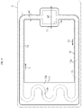
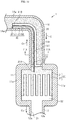
FIG. 1 is a pictorial plan view depicting a loop-type heat pipe in accordance with an embodiment. -
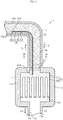
FIG. 2 is an enlarged plan view depicting a part of the loop-type heat pipe of the embodiment. -
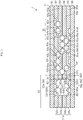
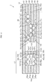
FIG. 3 is a schematic sectional view depicting a liquid pipe of the embodiment (a sectional view taken along aline 3A-3A inFIG. 2 ). -
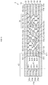
FIG. 4 is a schematic plan view illustrating a porous body of the embodiment. -
FIGS. 5A to 5E are schematic sectional views depicting a manufacturing method of the loop-type heat pipe of the embodiment. -
FIGS. 6A and 6B are schematic sectional views depicting the manufacturing method of the loop-type heat pipe of the embodiment. -
FIG. 7 is a schematic sectional view depicting a liquid pipe of a modified embodiment. -
FIG. 8 is a schematic sectional view depicting a liquid pipe of a modified embodiment. -
FIG. 9 is a schematic sectional view depicting a liquid pipe of a modified embodiment. -
FIG. 10 is a schematic plan view depicting a loop-type heat pipe of a modified embodiment. -
FIG. 11 is a schematic sectional view depicting a liquid pipe of the modified embodiment (a sectional view taken along aline 11A-11A inFIG. 10 ). -
FIG. 12 is a schematic plan view depicting a loop-type heat pipe of a modified embodiment. - Hereinbelow, embodiments will be described with reference to the accompanying drawings. In the meantime, for convenience, characteristic portions of the accompanying drawings may be shown in an enlarged manner for easy understanding of characteristics, and the dimensions and ratios of constitutional elements may be different in the respective drawings. Also, for easy understanding of the cross-sectional structure of each member, the hatching of some members is shown in a satin pattern and the hatching of some members is omitted in a cross-sectional view. In the meantime, as used herein, "as seen from above" indicates that a target object is seen in a vertical direction of
FIG. 3 and the like (an upper and lower direction in the drawings), and "planar shape" indicates a shape as seen in the vertical direction ofFIG. 3 and the like. - A loop-
type heat pipe 1 shown inFIG. 1 is accommodated in a mobile-typeelectronic device 2 such as a smart phone and a tablet terminal, for example. The loop-type heat pipe 1 includes anevaporator 11, avapor pipe 12, acondenser 13, and aliquid pipe 14. - The
evaporator 11 and thecondenser 13 are connected by thevapor pipe 12 and theliquid pipe 14. Theevaporator 11 has a function of vaporizing an operating fluid C to generate vapor Cv. The vapor Cv generated in theevaporator 11 is transported to thecondenser 13 through thevapor pipe 12. Thecondenser 13 has a function of condensing the vapor Cv of the operating fluid C. The condensed operating fluid C is transported to theevaporator 11 through theliquid pipe 14. Thevapor pipe 12 and theliquid pipe 14 form a loop-shaped flow path through which the operating fluid C or the vapor Cv is caused to flow. - The
vapor pipe 12 is formed as a long pipe body, for example. Theliquid pipe 14 is formed as a long pipe body, for example. In the present embodiment, thevapor pipe 12 and theliquid pipe 14 have the same size (i.e., a size in the longitudinal direction), for example. On the other hand, the length of thevapor pipe 12 and the length of theliquid pipe 14 may be different from each other. For example, the length of thevapor pipe 12 may be shorter than the length of theliquid pipe 14. As used herein, the "longitudinal direction" of theevaporator 11, thevapor pipe 12, thecondenser 13 and theliquid pipe 14 is a direction in which the operating fluid C or the vapor Cv flows in each member (refer to the arrow in the drawing). - The
evaporator 11 is closely fixed to a heat generation component (not shown). The operating fluid C in theevaporator 11 is vaporized by heat generated in the heat generation component, so that the vapor Cv is generated. In the meantime, a thermal conductive member (TIM: Thermal Interface Material) may be interposed between theevaporator 11 and the heat generation component. The thermal conductive member reduces a contact thermal resistance between the heat generation component and theevaporator 11, thereby implementing smooth heat conduction from the heat generation component to theevaporator 11. - The
vapor pipe 12 has a pair ofpipe walls 12w provided on both sides in a width direction orthogonal to the longitudinal direction of thevapor pipe 12, as seen from above, and aflow path 12r provided between the pair ofpipe walls 12w, for example. Theflow path 12r is formed to communicate with an internal space of theevaporator 11. Theflow path 12r is a part of the loop-shaped flow path. The vapor Cv generated in theevaporator 11 is guided to thecondenser 13 through thevapor pipe 12. - The
condenser 13 has aheat radiating plate 13p having a large area for heat radiation and a serpentine flow path 13r in theheat radiating plate 13p, for example. The flow path 13r is a part of the loop-shaped flow path. The vapor Cv guided through thevapor pipe 12 is condensed in thecondenser 13. In this way, in the loop-type heat pipe 1, the heat generated in the heat generation component is transferred to thecondenser 13 and is radiated in thecondenser 13. Thereby, the heat generation component is cooled, so that an increase in temperature of the heat generation component is suppressed. - The operating fluid C condensed in the
condenser 13 is guided to theevaporator 11 through theliquid pipe 14. Herein, a fluid having a high vapor pressure and a high evaporative latent heat is preferably used as the operating fluid C. Such operating fluid C is used, so that it is possible to effectively cool the heat generation component by the evaporative latent heat. As the operating fluid C, ammonia, water, Freon, alcohol, acetone and the like may be used, for example. - For example, a size W1 of the
liquid pipe 14 in the width direction orthogonal to the longitudinal direction, as seen from above, is smaller than a size W2 of theevaporator 11 in the width direction orthogonal to the longitudinal direction, as seen from above. - As shown in
FIG. 2 , theevaporator 11 is provided with aporous body 20. Theporous body 20 has aconnection part 21 and a plurality ofprotrusions 22. Theconnection part 21 is provided on a side in the internal space of theevaporator 11, which is the closest to the liquid pipe 14 (i.e., a side on which theliquid pipe 14 is connected to the evaporator 11), as seen from above, for example. Theconnection part 21 is formed to extend in the width direction (a right and left direction inFIG. 2 ) of theevaporator 11, for example. A surface of theconnection part 21 on the liquid pipe 14-side is in partial contact withpipe walls 11w of theevaporator 11 and the remaining thereof is in contact with a space S1, for example. A surface of theconnection part 21 on the vapor pipe 12-side is partially connected to theprotrusions 22 and the remaining thereof is in contact with a space S2. Each of theprotrusions 22 protrudes from theconnection part 21 toward thevapor pipe 12, as seen from above, for example. Each of theprotrusions 22 is formed to extend in the longitudinal direction of theevaporator 11, for example. The plurality ofprotrusions 22 is provided with predetermined intervals in the width direction of theevaporator 11, as seen from above, for example. An end portion of each of theprotrusions 22 on the vapor pipe 12-side is spaced from thepipe walls 11w of theevaporator 11. The end portions of therespective protrusions 22 on the vapor pipe 12-side are not connected to each other. That is, theporous body 20 of the present embodiment is formed to have a comb shape having theconnection part 21 and the plurality ofprotrusions 22, as seen from above. In the meantime, the number of the teeth of a comb of theporous body 20 can be changed as appropriate. - In the
evaporator 11, an area in which theporous body 20 is not provided is formed with a space S2. The space S2 is connected to theflow path 12r of thevapor pipe 12. - The
liquid pipe 14 has a pair ofpipe walls 14w provided at both ends of theliquid pipe 14 in the width direction, and aporous body 30 and avapor moving path 40 provided between the pair ofpipe walls 14w. - The
porous body 30 is formed to extend from the condenser 13 (refer toFIG. 1 ) to the vicinity of theevaporator 11 in the longitudinal direction of theliquid pipe 14, for example. Theporous body 30 is configured to guide the operating fluid C condensed in thecondenser 13 to theevaporator 11 by a capillary force that is generated in theporous body 30. Theporous body 30 has a plurality ofpores FIG. 3 ), for example. The plurality ofpores 62z to 65z functions as theflow path 14r through which the operating fluid C is to flow. Theflow path 14r is a part of the loop-shaped flow path. - A surface of the
porous body 30 on the evaporator 11-side is in contact with the space S1, for example. In the present embodiment, the space S1 is interposed between theporous body 30 of theliquid pipe 14 and theporous body 20 of theevaporator 11. On the other hand, the space S1 between theporous body 20 and theporous body 30 may be omitted. That is, theporous body 20 and theporous body 30 may be directly connected without the space S1. - The
vapor moving path 40 is formed to extend from theevaporator 11 in the longitudinal direction of theliquid pipe 14. Thevapor moving path 40 is formed to extend from theevaporator 11 to a point on the halfway in the longitudinal direction of theliquid pipe 14, along the longitudinal direction of theliquid pipe 14, for example. Thevapor moving path 40 is provided in the vicinity of onepipe wall 14w of the pair ofpipe walls 14w, for example. For example, thevapor moving path 40 is provided in the vicinity of thepipe wall 14w, which configures an inner side of a bent part of theliquid pipe 14, of the pair ofpipe walls 14w. Thevapor moving path 40 has, for example, apartitioning wall 41, apartitioning wall 42, aflow path 43, and aporous part 50. - The
partitioning wall 41 is formed to extend from the internal space of theevaporator 11 to a point on the halfway in the longitudinal direction of theliquid pipe 14, along the longitudinal direction of theliquid pipe 14. Anend portion 41A of thepartitioning wall 41 on the evaporator 11-side is formed to protrude into the internal space of theevaporator 11, for example. Theend portion 41A of thepartitioning wall 41 is formed to protrude into the inside of theporous body 20 of theevaporator 11, for example. For example, theend portion 41A of thepartitioning wall 41 is formed to protrude into the inside of theconnection part 21 of theporous body 20. Thepartitioning wall 42 is formed to extend from anend portion 41B, which is on an opposite side to theend portion 41A of thepartitioning wall 41 in the longitudinal direction, to thepipe wall 14w on one side (herein, a lower side inFIG. 2 ) along a width direction of theliquid pipe 14, for example. Thepartitioning wall 42 is formed to connect theend portion 41B of thepartitioning wall 41 and thepipe wall 14w. Thepartitioning wall 42 configures one end portion of thevapor moving path 40 in the longitudinal direction. One end portion of thevapor moving path 40 in the longitudinal direction is closed by thepartitioning wall 42 on the halfway of theliquid pipe 14 in the longitudinal direction. Thepartitioning walls flow path 43 of thevapor moving path 40 and theporous body 30 each other. Theflow path 43 and theporous body 30 are completely separated by thepartitioning walls flow path 43 is not communicating with theflow path 14r of theporous body 30. - The
flow path 43 of thevapor moving path 40 is configured by a space surrounded by thepartitioning wall 41, thepartitioning wall 42 and thepipe wall 14w. Theflow path 43 is formed to extend over an entire length of thevapor moving path 40 in the longitudinal direction. Theflow path 43 is separated from theporous body 30 over the entire length of thevapor moving path 40 in the longitudinal direction by thepartitioning walls partitioning walls pipe wall 14w function as a wall part surrounding theflow path 43. - The
flow path 43 is formed so that a cross-sectional area of a cross section obtained by cutting thevapor moving path 40 along a plane orthogonal to the longitudinal direction of thevapor moving path 40 is larger than a cross-sectional area of theflow path 14r of theporous body 30, for example. The cross-sectional area of theflow path 43 is formed smaller than a cross-sectional area of theflow path 12r of thevapor pipe 12, for example. - In the
vapor moving path 40, theporous part 50 is provided, for example. Theporous part 50 is formed to extend from the vicinity of theevaporator 11 to thepartitioning wall 42 along the longitudinal direction of thevapor moving path 40, for example. Theporous part 50 is configured to guide the operating fluid C condensed in thevapor moving path 40 to theevaporator 11 by a capillary force that is generated in theporous part 50, for example. Theporous part 50 and theporous body 30 are completed separated by thepartitioning walls vapor moving path 40 in the longitudinal direction. - A surface of the
porous part 50 on the evaporator 11-side is in contact with the space S1, for example. In the present embodiment, the space S1 is interposed between theporous part 50 and theporous body 20 of theevaporator 11. On the other hand, the space S1 between theporous part 50 and theporous body 20 may be omitted. That is, theporous part 50 and theporous body 20 may be directly connected without the space S1. - In the meantime, in
FIG. 2 , in order to show planar shapes of theporous body 30 andporous part 50 in theliquid pipe 14 and theporous body 20 in theevaporator 11, a metal layer (for example, ametal layer 61 shown inFIG. 3 ) that is the outermost layer of a plurality ofmetal layers 61 to 66 (which will be described later) is not shown. -
FIG. 3 is a cross-sectional view of theliquid pipe 14 taken along aline 3A-3A inFIG. 2 . This cross section is orthogonal to a direction in which the operating fluid C flows in the liquid pipe 14 (a direction denoted with the arrow inFIG. 2 ). - As shown in
FIG. 3 , theliquid pipe 14 has a structure where six layers ofmetal layers 61 to 66 are stacked, for example. In other words, theliquid pipe 14 has a structure where the metal layers 62 to 65, which are intermediate metal layers, are stacked between the metal layers 61 and 66 that are a pair of outermost layers. The metal layers 61 to 66 are copper layers having high heat conductivity, for example, and are directly bonded to each other by solid-phase bonding (for example, diffusion bonding, press bonding and ultrasonic bonding) and the like. Meanwhile, inFIG. 3 , the metal layers 61 to 66 are distinguished with solid lines for easy understanding. For example, when the metal layers 61 to 66 are integrated by diffusion bonding, interfaces between therespective metal layers 61 to 66 are lost, so that the interfaces may not be clear. As used herein, the solid-phase bonding is a method of heating and softening bonding targets in a solid state without melting the same, and then pressing, plastically deforming and bonding the bonding targets. - In the meantime, the metal layers 61 to 66 are not limited to the copper layers and may be formed of stainless steel, aluminum, magnesium alloy and the like. Also, for some of the stacked
metal layers 61 to 66, a material different from the other metal layers may be used. A thickness of each of the metal layers 61 to 66 may be set to about 50µm to 200µm, for example. In the meantime, some of the metal layers 61 to 66 may be formed to have a thickness different from the other metal layers. Also, all the metal layers may be formed to have thicknesses different from each other. - The
evaporator 11, thevapor pipe 12 and thecondenser 13 shown inFIG. 1 are respectively formed by stacking six layers of the metal layers 61 to 66, like theliquid pipe 14 shown inFIG. 3 . That is, the loop-type heat pipe 1 shown inFIG. 1 is configured by stacking six layers of the metal layers 61 to 66. In the meantime, the number of stacked metal layers is not limited to six, and may be five layers or less or seven layers or more. - As shown in
FIG. 3 , theliquid pipe 14 of the present embodiment consists of the stackedmetal layers 61 to 66, and has thepipe walls 14w, theporous body 30 and the vapor moving path 40 (thepartitioning walls flow path 43 and the porous part 50). In the meantime, in the present embodiment, the metal layers 61 and 66 of the metal layers 61 to 66 that are the outermost layers are not formed with a hole and a groove. The metal layers 61 and 66 function as a wall part (a top part or a bottom part) of theliquid pipe 14. - The
metal layer 62 has a pair ofwall parts 62w provided on both ends in a width direction (a right and left direction inFIG. 3 ) orthogonal to the stacking direction of the metal layers 61 to 66, and awall part 62t provided between the pair ofwall parts 62w. Themetal layer 62 has aporous body 62s provided between thewall part 62w on one side (herein, a right side inFIG. 3 ) and thewall part 62t and aporous part 62e provided between thewall part 62w on the other side (herein, a left side inFIG. 3 ) and thewall part 62t. - The
metal layer 63 has a pair ofwall parts 63w provided on both ends in the width direction and awall part 63t provided between the pair ofwall parts 63w. Themetal layer 63 has aporous body 63s provided between thewall part 63w on one side (herein, a right side inFIG. 3 ) and thewall part 63t and a through-hole 63X formed between thewall part 63w on the other side (herein, a left side inFIG. 3 ) and thewall part 63t and penetrating themetal layer 63 in a thickness direction. - The
metal layer 64 has a pair ofwall parts 64w provided on both ends in the width direction and awall part 64t provided between the pair ofwall parts 64w. Themetal layer 64 has aporous body 64s provided between thewall part 64w on one side (herein, a right side inFIG. 3 ) and thewall part 64t and a through-hole 64X formed between thewall part 64w on the other side (herein, a left side inFIG. 3 ) and thewall part 63t and penetrating themetal layer 64 in the thickness direction. - The
metal layer 65 has a pair ofwall parts 65w provided on both ends in the width direction, and awall part 65t provided between the pair ofwall parts 65w. Themetal layer 65 has aporous body 65s provided between thewall part 65w on one side (herein, a right side inFIG. 3 ) and the wall part 652t and aporous part 65e provided between thewall part 65w on the other side (herein, a left side inFIG. 3 ) and thewall part 65t. - Subsequently, a specific structure of each
pipe wall 14w is described. - Each
pipe wall 14w is configured by thewall parts 62w to 65w of theintermediate metal layers 62 to 65 of the metal layers 61 to 66. Eachpipe wall 14w is configured by the plurality of sequentially stackedwall parts 62w to 65w. Thewall parts 62w to 65w of the present embodiment are not formed with a hole and a groove. - Subsequently, a specific structure of the
porous body 30 is described. - The
porous body 30 is configured by theporous bodies 62s to 65s of theintermediate metal layers 62 to 65 of the metal layers 61 to 66. Theporous body 30 is configured by the plurality of sequentially stackedporous bodies 62s to 65s. - The
porous body 62s is formed with bottomedholes 62u recessed from an upper surface of themetal layer 62 to a substantially central part in the thickness direction and bottomedholes 62d recessed from a lower surface of themetal layer 62 to a substantially central part in the thickness direction. An inner wall of each of the bottomedholes metal layer 62 in the thickness direction) toward an opening side (upper and lower surfaces-side of the metal layer 62). In the meantime, the inner wall of each of the bottomedholes holes FIG. 8 and the like). As used herein, the "semicircular shape" includes a half circle obtained by bisecting a true circle, and circles of which arcs are longer or shorter than a half circle, for example. Also, as used herein, the "semi-elliptical shape" includes a semi-ellipse obtained by bisecting an ellipse, and ellipses of which arcs are longer or shorter than the semi-ellipse, for example. Also, the bottomedholes - As shown in
FIG. 4 , the bottomedholes holes holes holes 62u and the bottomedholes 62d partially overlap, as seen from above. As shown inFIGS. 3 and4 , in portions in which the bottomedholes 62u and the bottomedholes 62d overlap as seen from above, the bottomedholes 62u and the bottomedholes 62d partially communicate with each other, thereby formingpores 62z.FIG. 4 illustrates an arrangement state of the bottomedholes holes pores 62z. Theporous body 62s having the bottomedholes pores 62z configures a part of theporous body 30. - As shown in
FIG. 3 , theporous body 63s is formed with bottomedholes 63u recessed from an upper surface of themetal layer 63 to a substantially central part in the thickness direction and bottomedholes 63d recessed from a lower surface of themetal layer 63 to a substantially central part in the thickness direction. The bottomedholes holes metal layer 62. The bottomedholes 63u and the bottomedholes 63d partially overlap, as seen from above. In portions in which the bottomedholes 63u and the bottomedholes 63d overlap as seen from above, the bottomedholes 63u and the bottomedholes 63d partially communicate with each other, thereby formingpores 63z. Theporous body 63s having the bottomedholes pores 63z configures a part of theporous body 30. - The bottomed
holes 62d of themetal layer 62 and the bottomedholes 63u of themetal layer 63 are formed in overlapping positions, as seen from above, for example. For this reason, a pore is not formed at an interface between the bottomedhole 62d and the bottomedhole 63u. - The
porous body 64s is formed with bottomedholes 64u recessed from an upper surface of themetal layer 64 to a substantially central part in the thickness direction and bottomedholes 64d recessed from a lower surface of themetal layer 64 to a substantially central part in the thickness direction. The bottomedholes holes metal layer 62. The bottomedholes 64u and the bottomedholes 64d partially overlap, as seen from above. In portions in which the bottomedholes 64u and the bottomedholes 64d overlap as seen from above, the bottomedholes 64u and the bottomedholes 64d partially communicate with each other, thereby formingpores 64z. Theporous body 64s having the bottomedholes pores 64z configures a part of theporous body 30. - The bottomed
holes 63d of themetal layer 63 and the bottomedholes 64u of themetal layer 64 are formed in overlapping positions, as seen from above, for example. For this reason, a pore is not formed at an interface between the bottomedhole 63d and the bottomedhole 64u. - The
porous body 65s is formed with bottomedholes 65u recessed from an upper surface of themetal layer 65 to a substantially central part in the thickness direction and bottomedholes 65d recessed from a lower surface of themetal layer 65 to a substantially central part in the thickness direction. The bottomedholes holes metal layer 62. The bottomedholes 65u and the bottomedholes 65d partially overlap, as seen from above. In portions in which the bottomedholes 65u and the bottomedholes 65d overlap as seen from above, the bottomedholes 65u and the bottomedholes 65d partially communicate with each other, thereby formingpores 65z. Theporous body 65s having the bottomedholes pores 65z configures a part of theporous body 30. - The bottomed
holes 64d of themetal layer 64 and the bottomedholes 65u of themetal layer 65 are formed in overlapping positions, as seen from above, for example. For this reason, a pore is not formed at an interface between the bottomedhole 64d and the bottomedhole 65u. - The
pores respective metal layers 62 to 65 communicate with each other. Thepores porous body 30. The operating fluid C is spread three-dimensionally in thepores 62z to 65z that communicate with each other by the capillary force. In this way, thepores 62z to 65z function as theflow path 14r in which the liquid-phase operating fluid C flows. - Subsequently, a specific structure of the vapor moving path 40 (the
partitioning walls flow path 43 and the porous body 50) is described. - The
partitioning wall 41 is configured by thewall parts 62t to 65t of theintermediate metal layers 62 to 65 of the metal layers 61 to 66. Thepartitioning wall 41 is configured by the plurality of sequentially stackedwall parts 62t to 65t. Although not shown, thepartitioning wall 42 is configured by thewall parts 62t to 65t of theintermediate metal layers 62 to 65 of the metal layers 61 to 66, like thepartitioning wall 41. Thewall parts 62t to 65t of the present embodiment are not formed with a hole and a groove. - The
flow path 43 is configured by the through-holes intermediate metal layers metal layers 61 to 66 in the thickness direction. Themetal layer 63 and themetal layer 64 are stacked so that the through-holes - The
metal layer 62 is stacked on an upper surface of themetal layer 63, and themetal layer 65 is stacked on a lower surface of themetal layer 64. Theflow path 43 is defined by the metal layers 62 to 65 and the through-holes flow path 43 is surrounded by thewall parts partitioning walls wall parts pipe wall 14w, and the metal layers 62 and 65. In other words, thewall part wall part flow path 43. - The
porous part 50 is configured by theporous parts porous part 62e is provided immediately above theflow path 43. Theporous part 65e is provided immediately below theflow path 43. - The
porous part 62e extends in the longitudinal direction of theflow path 43. Theporous part 62e is formed in contact with theflow path 43. Theporous part 62e is formed in themetal layer 62 that functions as a wall part surrounding theflow path 43. Theporous part 62e is formed with bottomedholes 62f recessed from an upper surface of themetal layer 62 to a substantially central part in the thickness direction and bottomedholes 62g recessed from a lower surface of themetal layer 62 to a substantially central part in the thickness direction. The bottomedholes holes porous body 62s. The bottomedholes 62f and the bottomedholes 62g partially overlap, as seen from above. In portions in which the bottomedholes 62f and the bottomedholes 62g overlap as seen from above, the bottomedholes 62f and the bottomedholes 62g partially communicate with each other, thereby formingpores 62h. The bottomedholes 62g communicate with the flow path 43 (specifically, the through-hole 63X of the metal layer 63). The bottomedholes pores 62h may have similar shapes to the bottomedholes pores 62z of theporous body 62s. - The
metal layer 65 has theporous part 65e formed immediately below theflow path 43. Theporous part 65e extends in the longitudinal direction of theflow path 43. Theporous part 65e is formed in contact with theflow path 43. Theporous part 65e is formed in themetal layer 65 that functions as a wall part surrounding theflow path 43. Theporous part 65e is formed with bottomedholes 65f recessed from an upper surface of themetal layer 65 to a substantially central part in the thickness direction and bottomedholes 65g recessed from a lower surface of themetal layer 65 to a substantially central part in the thickness direction. The bottomedholes holes porous body 62s. The bottomedholes 65f and the bottomedholes 65g partially overlap, as seen from above. In portions in which the bottomedholes 65f and the bottomedholes 65g overlap as seen from above, the bottomedholes 65f and the bottomedholes 65g partially communicate with each other, thereby formingpores 65h. The bottomedholes 65f communicate with the flow path 43 (specifically, the through-hole 64X of the metal layer 64). The bottomedholes pores 65h may have similar shapes to the bottomedholes pores 62z of theporous body 62s. - As described above, the
vapor moving path 40 has theflow path 43. Theflow path 43 is surrounded by the twoporous parts wall parts partitioning walls wall parts pipe wall 14w. In theflow path 43, the operating fluid vaporized in theevaporator 11, i.e., the vapor Cv flows. As shown inFIG. 2 , the vapor Cv moves in theflow path 43 from theevaporator 11 toward thepartitioning wall 42 along the longitudinal direction of theflow path 43. - The
liquid pipe 14 is provided with an inlet for injecting the operating fluid C (refer toFIG. 2 ), although not shown. However, the inlet is blocked by a seal member, so that an inside of the loop-type heat pipe 1 is air-tightly maintained. Also, although not shown, theporous body 20 provided in theevaporator 11 has a similar structure to theporous body 30 shown inFIGS. 3 and4 . - Subsequently, operations of the loop-
type heat pipe 1 are described. - The loop-
type heat pipe 1 includes theevaporator 11 configured to vaporize the operating fluid C, thecondenser 13 configured to condense the vapor Cv, thevapor pipe 12 for causing the vaporized operating fluid (i.e., the vapor Cv) to flow into thecondenser 13, and theliquid pipe 14 for causing the condensed operating fluid C to flow into theevaporator 11. - The
liquid pipe 14 is provided with theporous body 30. Theporous body 30 extends from thecondenser 13 to the vicinity of theevaporator 11 along the longitudinal direction of theliquid pipe 14. Theporous body 30 is configured to guide the liquid-phase operating fluid C condensed in thecondenser 13 to theevaporator 11 by the capillary force that is generated in theporous body 30. - In the
evaporator 11, the liquid-phase operating fluid C is introduced into the porous body 20 (theconnection part 21 and the like), which is adjacent to theliquid pipe 20, of theporous body 20. In theevaporator 11, the liquid-phase operating fluid C is vaporized by the heat generated in the heat generation component (not shown), so that the vapor Cv is generated. The generated vapor Cv flows into theflow path 12r of thevapor pipe 12 and also flows into theflow path 43 of thevapor moving path 40 provided in theliquid pipe 14. The cross-sectional area of theflow path 43 is formed smaller than the cross-sectional area of theflow path 12r of thevapor pipe 12. For this reason, most of the vapor Cv generated in theevaporator 11 flows into theflow path 12r of thevapor pipe 12, and only a part of the vapor Cv generated in theevaporator 11 flows into theflow path 43 of thevapor moving path 40. - In the
flow path 43, the vapor Cv generated in theevaporator 11 moves from theevaporator 11 toward thepartitioning wall 42 along the longitudinal direction of theflow path 43. The vapor Cv moves in theflow path 43 in this way, so that the operating fluid C introduced into theporous body 30 of theliquid pipe 14 can be warmed by the evaporative latent heat (latent heat of vaporization) of the vapor Cv. Thereby, for example, even when theelectronic device 2 including the loop-type heat pipe 1 is used in environments in which an ambient temperature is lower than the freezing point of the operating fluid C, such as cold regions and winter, it is possible to favorably suppress the liquid-phase operating fluid C in theliquid pipe 14 from being phase-transformed into solid phase. - Herein, when the vapor Cv flows in the
flow path 43, the vapor Cv may be condensed in theflow path 43, in some cases. When the condensed operating fluid C stays in theflow path 43, the operating fluid C may be phase-transformed into solid phase. However, thevapor moving path 40 of the present embodiment is provided with theporous part 50. Theporous part 50 extends from thepartitioning wall 42, which is an end portion of thevapor moving path 40 in the longitudinal direction, to the vicinity of theevaporator 11 along the longitudinal direction of thevapor moving path 40. Theporous part 50 guides the liquid-phase operating fluid C condensed in theflow path 43 to theevaporator 11 by the capillary force that is generated in theporous part 50. Thereby, even when the vapor Cv is condensed in theflow path 43, the condensed operating fluid C can be caused to flow back toward theevaporator 11, so that the condensed operating fluid C can be suppressed from staying in theflow path 43. As a result, it is possible to favorably suppress the operating fluid C in theflow path 43 from being phase-transformed into solid phase. - Subsequently, a manufacturing method of the loop-
type heat pipe 1 is described. - First, in a process shown in
FIG. 5A , ametal sheet 80 having a flat plate shape is prepared. Themetal sheet 80 is a member that is to eventually become the metal layer 62 (refer toFIG. 3 ). Themetal sheet 80 is formed of copper, stainless steel, aluminum, magnesium alloy or the like, for example. A thickness of themetal sheet 80 may be set to about 50µm to 200µm, for example. - Then, in a process shown in
FIG. 5B , a resistlayer 81 is formed on an upper surface of themetal sheet 80, and a resistlayer 82 is formed on a lower surface of themetal sheet 80. For the resistlayers - Subsequently, in a process shown in
FIG. 5C , the resistlayer 81 is exposed and developed to form openingportions metal sheet 80. Likewise, the resistlayer 82 is exposed and developed to form openingportions metal sheet 80. The openingportions holes FIG. 3 . The openingportions holes FIG. 3 . In the meantime, parts of themetal sheet 80 corresponding to thewall parts FIG. 3 ) are covered with the resistlayers - Subsequently, in a process shown in
FIG. 5D , themetal sheet 80 exposed in the openingportions metal sheet 80, and themetal sheet 80 exposed in the openingportions metal sheet 80. The bottomedholes 62u are formed on the upper surface-side of themetal sheet 80 by the openingportions 81X, and the bottomedholes 62d are formed on the lower surface-side of themetal sheet 80 by the openingportions 82X. The bottomedholes 62u and the bottomedholes 62d are formed to partially overlap, as seen from above, and in the overlapping portions, the bottomedholes 62u and the bottomedholes 62d communicate with each other, so that thepores 62z are formed. Also, the bottomedholes 62f are formed on the upper surface-side of themetal sheet 80 by the openingportions 81Y, and the bottomedholes 62g are formed on the lower surface-side of themetal sheet 80 by the openingportions 82Y. The bottomedholes 62f and the bottomedholes 62g are formed to partially overlap, as seen from above, and in the overlapping portions, the bottomedholes 62f and the bottomedholes 62g communicate with each other, so that thepores 62h are formed. When etching themetal sheet 80, a ferric chloride solution may be used, for example. - Subsequently, the resist
layers FIG. 5E , themetal layer 62 having the pair ofwall parts 62w, thewall part 62t, theporous body 62s and theporous part 62e can be formed. - Subsequently, in a process shown in
FIG. 6A ,solid metal layers FIGS. 5A to 5E , the metal layers 63, 64 and 65 are formed. In the meantime, shapes and positions of the bottomed holes, the pores and the through-holes formed in the metal layers 63, 64 and 65 are as shown inFIG. 3 , for example. - Subsequently, in a process shown in
FIG. 6B , the metal layers 62, 63, 64, 65 and 66 are stacked in order below themetal layer 61, and are then pressurized and heated for solid-phase bonding. For example, the metal layers 61, 62, 63, 64, 65 and 66 stacked while heating the same at a predetermined temperature (for example, about 900°C) are pressed, so that the metal layers 61, 62, 63, 64, 65 and 66 are bonded by solid-phase bonding. Thereby, the metal layers 61, 62, 63, 64, 65 and 66 adjacent to each other are directly bonded, so that the loop-type heat pipe 1 including theevaporator 11, thecondenser 13, thevapor pipe 12 and theliquid pipe 14 shown inFIG. 1 is formed. Also, theliquid pipe 14 is formed with theporous body 30 and thevapor moving path 40, and theevaporator 11 is formed with theporous body 20. - Thereafter, the
liquid pipe 14 is exhausted by using a vacuum pump and the like, and the operating fluid C is injected from the inlet (not shown) into theliquid pipe 14. Thereafter, the inlet is sealed. - In the below, effects of the present embodiment are described.
- (1) The
liquid pipe 14 is provided with theporous body 30, and thevapor moving path 40. Thevapor moving path 40 is provided in a part of theliquid pipe 14 separately from theporous body 30 and extending from theevaporator 11 along the longitudinal direction of theliquid pipe 14, wherein the operating fluid (i.e., the vapor Cv) vaporized in theevaporator 11 moves in thevapor moving path 40. The vapor Cv moves in thevapor moving path 40, so that the operating fluid C introduced into theporous body 30 of theliquid pipe 14 can be warmed by the evaporative latent heat (latent heat of vaporization) of the vapor Cv. Thereby, for example, even when theelectronic device 2 including the loop-type heat pipe 1 is used in environments in which an ambient temperature is lower than the freezing point of the operating fluid C, such as cold regions and winter, it is possible to favorably suppress the liquid-phase operating fluid C in theliquid pipe 14 from being phase-transformed into solid phase. For this reason, it is possible to favorably perform heat transport in the loop-type heat pipe 1 by using phase transform of the operating fluid C. As a result, even when theelectronic device 2 is used in cold regions and the like, the heat generation component can be favorably cooled. - (2) The
vapor moving path 40 is provided with theporous part 50. Theporous part 50 extends from thepartitioning wall 42, which is an end portion of thevapor moving path 40 in the longitudinal direction, to the vicinity of theevaporator 11 along the longitudinal direction of thevapor moving path 40. Theporous part 50 guides the liquid-phase operating fluid C condensed in theflow path 43 to theevaporator 11 by the capillary force that is generated in theporous part 50. Thereby, even when the vapor Cv is condensed in theflow path 43, the condensed operating fluid C can be caused to flow back toward theevaporator 11, so that the condensed operating fluid C can be suppressed from staying in theflow path 43. As a result, it is possible to favorably suppress the operating fluid C in theflow path 43 from being phase-transformed into solid phase. - (3) The
porous part 50 is formed in the wall part (herein, the metal layers 62 and 65) except thepartitioning walls flow path 43 and theporous body 30 of the wall part (herein, thepartitioning walls pipe walls 14w and the metal layers 62 and 65) surrounding theflow path 43. Thereby, theporous part 50 is not interposed between theflow path 43 through which the vapor Cv moves and theporous body 30. For this reason, it is possible to favorably warm the operating fluid C introduced into theporous body 30 by the evaporative latent heat of the vapor Cv that moves in theflow path 43. Also, theflow path 43 of thevapor moving path 40 and theflow path 14r of theporous body 30 are completely separated by thepartitioning walls flow path 43 can be enabled not to flow into theporous body 30. For this reason, it is possible to favorably maintain the flowing of the operating fluid C in theflow path 14r. - (4) The
partitioning wall 41 of the wall part surrounding theflow path 43 is formed to protrude into the internal space of theevaporator 11. According to this configuration, it is possible to favorably partition the area, in which theporous body 30 is formed, of theliquid pipe 14 and theflow path 43 of thevapor moving path 40 each other. Thereby, for example, it is possible to favorably suppress the liquid-phase operating fluid C guided to theevaporator 11 by theporous body 30 from flowing into thevapor moving path 40, as it is liquid phase. - (5) The
partitioning wall 41 of the wall part surrounding theflow path 43 is formed to protrude into the inside of theconnection part 21 of theporous body 20 provided in theevaporator 11. According to this configuration, theporous body 20 facing theflow path 43 and theporous body 20 facing theporous body 30 are partitioned each other by thepartitioning wall 41. Thereby, the liquid-phase operating fluid C guided to theevaporator 11 by theporous body 30 can be favorably suppressed from being vaporized and flowing into theflow path 43 before it is introduced into theentire connection part 21. As a result, it is possible to favorably suppress the vapor Cv generated in the evaporator 11 from mainly flowing into theflow path 43. - (6) The wall part surrounding the
flow path 43 includes thepipe walls 14w of theliquid pipe 14 and thepartitioning walls pipe walls 14w of theliquid pipe 14 are used as the wall part surrounding theflow path 43. Thereby, as compared to a configuration in which the wall part surrounding theflow path 43 is formed without using thepipe walls 14w, it is possible to secure a wider space in which the operating fluid C condensed in thecondenser 13 flows (i.e., the space in which theporous body 30 is formed). - (7) The cross-sectional area of the
flow path 43 of thevapor moving path 40 is formed greater than the cross-sectional area of theflow path 14r of theporous body 30, and smaller than the cross-sectional area of theflow path 12r of thevapor pipe 12. Thereby, while most of the vapor Cv generated in theevaporator 11 can be caused to flow into theflow path 12r of thevapor pipe 12, a part of the vapor Cv generated in theevaporator 11 can be caused to flow into theflow path 43 of thevapor moving path 40. - The above embodiment can be changed and implemented, as follows. The above embodiment and following embodiments can be combined with each other without technology inconsistency.
- In the below, each modified embodiment of the
liquid pipe 14 is described. In the meantime, in each modified embodiment, the same constitutional elements as the above embodiment and the same constitutional elements among the respective modified embodiments are denoted with the same reference signs, and the descriptions thereof may be partially or entirely omitted. In the meantime, since the parts other than the liquid pipe are the same as the above embodiment (refer toFIG. 1 ), the drawings and descriptions are omitted while referring toFIG. 1 and the like - In the
vapor moving path 40 of the above embodiment, the wall part, which faces in the stacking direction of the metal layers 61 to 66, of the wall part surrounding theflow path 43, i.e., the metal layers 62 and 65 are provided with the porous part 50 (theporous parts porous part 50. Also, thepipe walls 14w (thewall parts 62w to 65w) or thepartitioning walls 41 and 42 (thewall parts 62t to 65t) of the wall part surrounding theflow path 43 may be provided with theporous part 50. In this case, for example, a part of thewall parts 62w to 65w configuring thepipe wall 14w may be provided with theporous part 50 integrally and continuously from thewall parts 62w to 65w. Also, a part of thewall parts 62t to 65t configuring thepartitioning walls porous part 50 integrally and continuously from thewall parts 62t to 65t. In any case, theporous part 50 is formed in contact with theflow path 43. - In the
vapor moving path 40 of the above embodiment, the wall part surrounding theflow path 43 is provided with theporous part 50. However, the present disclosure is not limited thereto. For example, the wall part surrounding theflow path 43 may be formed with a groove portion, instead of theporous part 50. A shape of the groove portion is not particularly limited inasmuch as it can guide the operating fluid C condensed in theflow path 43 to theevaporator 11 by a capillary force that is generated in the groove portion. - For example, as shown in
FIG. 7 , in thevapor moving path 40, thepipe wall 14w of theliquid pipe 14 may be formed withgroove portions flow path 43, of side surfaces of thepipe wall 14w is formed withlinear groove portions vapor moving path 40. Thegroove portions wall parts 62w to 65w configuring thepipe wall 14w, for example. In the modified embodiment ofFIG. 7 , widths of thewall parts wall parts 62w to 65w are made smaller than widths of thewall parts groove portions groove portion 91 is configured by a step formed by a side surface of thewall part 62w, a side surface of thewall part 63w and a side surface of thewall part 64w. Thegroove portion 92 is configured by a step formed by a side surface of thewall part 64w and a side surface of thewall part 65w. Thegroove portions flow path 43. Thegroove portions flow path 43 to the evaporator 11 (refer toFIG. 2 ) by a capillary force that is generated in thegroove portions - Meanwhile, in this modified embodiment, the
porous parts FIG. 3 are omitted. In this case, theflow path 43 is surrounded by thewall parts 62w to 65w configuring thepipe wall 14w, thewall parts 62t to 65t configuring thepartitioning walls flow path 43 is configured by through-holes intermediate metal layers 62 to 65 of the stackedmetal layers 61 to 66 in the thickness direction. The metal layers 62 to 65 are stacked so that the respective through-holes - For example, in the
liquid pipe 14 ofFIG. 8 , groove portions formed in a side surface of thepipe wall 14w are different fromFIG. 7 . A side surface, which is in contact with theflow path 43, of the side surfaces of thepipe wall 14w is formed withlinear groove portions 62k to 65k extending in the longitudinal direction of thevapor moving path 40. Thegroove portions 62k to 65k each have an arc-shaped section. Thegroove portions 62k to 65k are formed recessed from the upper surfaces of thewall parts 62w to 65w configuring thepipe wall 14w to a central part in the thickness direction, for example. For example, thegroove portions 62k to 65k are formed by half etching thewall parts 62w to 65w from the upper surfaces thereof. Thegroove portions 62k to 65k are formed to communicate with theflow path 43. Thegroove portions 62k to 65k can guide the operating fluid C condensed in theflow path 43 to theevaporator 11 by a capillary force that is generated in thegroove portions 62k to 65k. - For example, in the
liquid pipe 14 ofFIG. 9 , groove portions formed in a side surface of thepipe wall 14w are different fromFIG. 8 , and the metal layers 61 and 66 are formed with groove portions. A side surface, which is in contact with theflow path 43, of the side surfaces of thepipe wall 14w is formed with linear groove portions 61k2, 62k1, 62k2, 63k1, 63k2, 64k1, 64k2, 65k1, 65k2 and 66k1 extending in the longitudinal direction of thevapor moving path 40. - The groove portion 62k1 is formed by half etching the
wall part 62w configuring thepipe wall 14w from the upper surface-side thereof, for example. The groove portion 62k2 is formed by half etching thewall part 62w configuring thepipe wall 14w from the lower surface-side thereof, for example. The groove portion 63k1 is formed by half etching thewall part 63w configuring thepipe wall 14w from the upper surface-side thereof, for example. The groove portion 63k2 is formed by half etching thewall part 63w configuring thepipe wall 14w from the lower surface-side thereof, for example. The groove portion 64k1 is formed by half etching thewall part 64w configuring thepipe wall 14w from the upper surface-side thereof, for example. The groove portion 64k2 is formed by half etching thewall part 64w configuring thepipe wall 14w from the lower surface-side thereof, for example. The groove portion 65k1 is formed by half etching thewall part 65w configuring thepipe wall 14w from the upper surface-side thereof, for example. The groove portion 65k2 is formed by half etching thewall part 65w configuring thepipe wall 14w from the lower surface-side thereof, for example. The groove portion 61k2 is formed by half etching theoutermost metal layer 61 from the lower surface-side, for example. The groove portion 66k1 is formed by half etching theoutermost metal layer 66 from the upper surface-side, for example. The groove portions 61k2, 62k1, 62k2, 63k1, 63k2, 64k1, 64k2, 65k1, 65k2 and 66k1 are formed to have an arc-shaped section, for example. The groove portions 61k2, 62k1, 62k2, 63k1, 63k2, 64k1, 64k2, 65k1, 65k2 and 66k1 are formed to communicate with theflow path 43. The groove portions 61k2, 62k1, 62k2, 63k1, 63k2, 64k1, 64k2, 65k1, 65k2 and 66k1 can guide the operating fluid C condensed in theflow path 43 to theevaporator 11 by a capillary force that is generated in the groove portions. - In the modified embodiments of
FIGS. 7 to 9 , the side surface of thepipe wall 14w is formed with the groove portions. However, the side surfaces of thepartitioning walls metal layer 61 or on the upper surface of themetal layer 66. - In the modified embodiments of
FIGS. 7 to 9 , theporous parts FIG. 3 may be formed. - In the above embodiment, the structure other than the
vapor moving path 40 of theliquid pipe 14 is not particularly limited inasmuch as it can guide the operating fluid C condensed in thecondenser 13 to theevaporator 11. For example, a part of theliquid pipe 14 other than thevapor moving path 40 may be formed with a space in which theporous body 30 is not formed. This space functions as a flow path in which the operating fluid C condensed in thecondenser 13 flows. - For example, as shown in
FIG. 10 , a space in which theporous body 30 is not formed, i.e., aflow path 14t in which the operating fluid C condensed in thecondenser 13 flows may be formed between thevapor moving path 40 and theporous body 30, adjacent to thevapor moving path 40. Theflow path 14t is formed in contact with thepartitioning wall 41 of thevapor moving path 40, for example. Theflow path 14t is formed in contact with theporous body 30, for example. Theflow path 14t is formed to extend in the longitudinal direction of thevapor moving path 40, for example. In other words, theflow path 14t is not communicating with theflow path 43 of thevapor moving path 40 and theflow pat 14t is communicating with theflow path 14r of theporous body 30. - As shown in
FIG. 11 , theflow path 14t is configured by through-holes intermediate metal layers 62 to 65 of the stackedmetal layers 61 to 66 in the thickness direction. The metal layers 62 to 65 are stacked so that the respective through-holes hole 62Y is formed to communicate with at least one (inFIG. 11 , the bottomedhole 62d) of the bottomedholes porous body 62s of themetal layer 62, for example. The through-hole 63Y is formed to communicate with at least one (inFIG. 11 , the bottomedhole 63u) of the bottomedholes porous body 63s of themetal layer 63, for example. The through-hole 64Y is formed to communicate with at least one (not shown inFIG. 11 ) of the bottomedholes porous body 64s of themetal layer 64, for example. The through-hole 65Y is formed to communicate with at least one (inFIG. 11 , the bottomedhole 65d) of the bottomedholes porous body 65s of themetal layer 65, for example. - The
flow path 14t as described above is provided, so that it is possible to increase an amount by which the operating fluid C condensed in thecondenser 13 can be stored in theliquid pipe 14, as compared to a configuration in which theflow path 14t is not provided. Also, since theflow path 14t is provided adjacent to thevapor moving path 40, it is possible to increase an amount of the operating fluid C that can be warmed by the vapor Cv moving in theflow path 43 of thevapor moving path 40. - In the modified embodiment of
FIG. 10 , theflow path 14t is formed to extend from theevaporator 11 to a point on the halfway in the longitudinal direction of theliquid pipe 14. However, the present disclosure is not limited thereto. For example, theflow path 14t may be formed to extend over an entire length in the longitudinal direction of theliquid pipe 14. - The shapes of the bottomed holes shown in the above embodiment may be changed as appropriate.
- In the above embodiment, a depth of the bottomed hole on the upper surface-side and a depth of the bottomed hole on the lower surface-side may be different from each other.
- The
porous bodies porous part 50 of the above embodiment have the structure including the metal layers having first bottomed holes recessed from the upper surface-side, second bottomed holes recessed from the lower surface-side, and pores formed as the first bottomed holes and the second bottomed holes partially communicate with each other. However, the present disclosure is not limited thereto. For example, theporous bodies porous part 50 may have such a configuration that a first metal layer having first through-holes penetrating in the thickness direction and a second metal layer having second through-holes penetrating in the thickness direction are provided and the first metal layer and the second metal layer are stacked so that the first through-holes and the second through-holes partially overlap each other. In this case, pores communicating with each other in portions in which the first through-holes and the second through-holes partially overlap are formed. - In the above embodiment, the formation position of the
vapor moving path 40 is not particularly limited. That is, the formation position of thevapor moving path 40 is not particularly limited inasmuch as thevapor moving path 40 is formed to extend from theevaporator 11 in the longitudinal direction of theliquid pipe 14. - For example, as shown in
FIG. 12 , thevapor moving path 40 may be provided in the vicinity of thepipe wall 14w, which configures an outer side of the bent part of theliquid pipe 14, of the pair ofpipe walls 14w. In the meantime, when thepipe wall 14w configuring the outer side of the bent part of theliquid pipe 14 is provided with the inlet for the operating fluid C, thevapor moving path 40 is formed so as not to overlap the inlet. - Also, the
vapor moving path 40 may be provided in a central part of theliquid pipe 14 in the width direction. - The
liquid pipe 14 of the above embodiment may be provided with a plurality ofvapor moving paths 40.
Claims (10)
- A loop-type heat pipe (1) comprising:an evaporator (11) configured to vaporize an operating fluid (C);a condenser (13) configured to condense the operating fluid (C);a liquid pipe (14) configured to connect the evaporator (11) and the condenser (13);a vapor pipe (12) configured to connect the evaporator (11) and the condenser (13);a porous body (30) provided in the liquid pipe (14); anda vapor moving path (40) provided at a part in the liquid pipe (14) separately from the porous body (30) and extending from the evaporator (11) along a longitudinal direction of the liquid pipe (14), the operating fluid vaporized in the evaporator (11) moving in the vapor moving path (40),wherein the vapor moving path (40) has a flow path (43) in which the operating fluid vaporized in the evaporator (11) flows and a wall part (41, 42, 14w, 61, 62, 65, 66) surrounding the flow path (43).
- The loop-type heat pipe according to Claim 1, wherein the vapor moving path (40) has a porous part (50, 62e, 65e) formed in contact with the flow path (43).
- The loop-type heat pipe according to Claim 2, wherein the wall part (41, 42, 14w, 61, 62, 65, 66) has a partitioning wall (41, 42) configured to partition the flow path (43) and the porous body (30) each other, and the porous part (50, 62e, 65e) is formed in a portion other than the partitioning wall (41, 42) of the wall part (41, 42, 14w, 61, 62, 65, 66).
- The loop-type heat pipe according to Claim 2 or 3, wherein the porous part (50, 62e, 65e) comprises a metal layer (62, 65) having first bottomed holes (62f, 65f) recessed from one surface, second bottomed holes (62g, 65g) recessed from the other surface, and pores (62h, 65h) formed as the first bottomed holes and the second bottomed holes partially communicate with each other.
- The loop-type heat pipe according to one of Claims 2 to 4, wherein the partitioning wall (41, 42) is formed to protrude into an internal space of the evaporator (11).
- The loop-type heat pipe according to Claim 5, wherein the wall part (41, 42, 14w, 61, 62, 65, 66) has a pipe wall (12w) of the liquid pipe (14).
- The loop-type heat pipe according to one of Claims 1 to 6, wherein the vapor moving path (40) has a groove portion (91, 92, 62k to 65k, 61k2, 62k1, 62k2, 63k1, 63k2, 64k1, 64k2, 65k1, 65k2 and 66k1) formed in the wall part (41, 42, 14w, 61, 62, 65, 66) so as to be in contact with the flow path (43).
- The loop-type heat pipe according to one of Claims 1 to 7, wherein a cross-sectional area of the flow path (43) of the vapor moving path (40) is formed greater than a cross-sectional area of a flow path (14r) of the porous body (30) and smaller than a cross-sectional area of a flow path (12r) of the vapor pipe (12).
- The loop-type heat pipe according to one of Claims 1 to 8, wherein the vapor moving path (40) is formed to extend from the evaporator (11) to a point on the halfway in the longitudinal direction of the liquid pipe (14), and an end portion of the vapor moving path (40) at a part on the halfway is blocked.
- The loop-type heat pipe according to one of Claims 1 to 9, wherein the liquid pipe (14) has a flow path (14t) in which the operating fluid (C) condensed in the condenser (13) flows, and the flow path (14t) of the liquid pipe (14) is provided between the vapor moving path (40) and the porous body (30), and adjacent to the vapor moving path (40).
Applications Claiming Priority (1)
| Application Number | Priority Date | Filing Date | Title |
|---|---|---|---|
| JP2019102791A JP7210379B2 (en) | 2019-05-31 | 2019-05-31 | loop heat pipe |
Publications (2)
| Publication Number | Publication Date |
|---|---|
| EP3745073A1 true EP3745073A1 (en) | 2020-12-02 |
| EP3745073B1 EP3745073B1 (en) | 2022-11-02 |
Family
ID=70921805
Family Applications (1)
| Application Number | Title | Priority Date | Filing Date |
|---|---|---|---|
| EP20177201.9A Active EP3745073B1 (en) | 2019-05-31 | 2020-05-28 | Loop-type heat pipe |
Country Status (4)
| Country | Link |
|---|---|
| US (1) | US11592240B2 (en) |
| EP (1) | EP3745073B1 (en) |
| JP (1) | JP7210379B2 (en) |
| CN (1) | CN112013703B (en) |
Families Citing this family (3)
| Publication number | Priority date | Publication date | Assignee | Title |
|---|---|---|---|---|
| JP7525438B2 (en) * | 2021-04-26 | 2024-07-30 | 新光電気工業株式会社 | Loop Heat Pipe |
| WO2024238449A1 (en) * | 2023-05-12 | 2024-11-21 | The Regents Of The University Of California | Salt-rejecting continuous passive solar thermal desalination via thin-film condensation |
| US12546541B2 (en) * | 2024-05-14 | 2026-02-10 | Long Victory Instruments Co., Ltd. | Liquid-gas phase-transition evaporator conducive to mounting a capillary structure in place |
Citations (4)
| Publication number | Priority date | Publication date | Assignee | Title |
|---|---|---|---|---|
| CN201463680U (en) * | 2009-09-04 | 2010-05-12 | 苏州聚力电机有限公司 | Pipe body looped heat pipe |
| JP2015183880A (en) * | 2014-03-20 | 2015-10-22 | 富士通株式会社 | Loop type heat pipe, its process of manufacture, and electronic apparatus |
| US20160259383A1 (en) * | 2013-12-13 | 2016-09-08 | Fujitsu Limited | Loop heat pipe, method of manufacturing the same, and electronic device |
| US20180142960A1 (en) * | 2016-11-18 | 2018-05-24 | Shinko Electric Industries Co., Ltd. | Loop heat pipe |
Family Cites Families (17)
| Publication number | Priority date | Publication date | Assignee | Title |
|---|---|---|---|---|
| US3537515A (en) * | 1969-08-28 | 1970-11-03 | Ambrose W Byrd | Power system with heat pipe liquid coolant lines |
| ZA824373B (en) | 1981-07-20 | 1984-02-29 | Ppg Industries Inc | Ungelled polyepoxide-polyoxyalkylenepolyamine resins,aqueous dispersions thereof,and their use in cationic electrodeposition |
| JPH0724293B2 (en) * | 1987-09-30 | 1995-03-15 | 株式会社日立製作所 | Boiling cooler |
| JP3970514B2 (en) * | 2000-10-13 | 2007-09-05 | 三菱電機株式会社 | Loop heat exchange heat transport equipment |
| US7748436B1 (en) * | 2006-05-03 | 2010-07-06 | Advanced Cooling Technologies, Inc | Evaporator for capillary loop |
| JP2012132661A (en) * | 2010-12-01 | 2012-07-12 | Fujitsu Ltd | Cooling device and electronic device |
| JP5741354B2 (en) * | 2011-09-29 | 2015-07-01 | 富士通株式会社 | Loop heat pipe and electronic equipment |
| JP6191137B2 (en) * | 2012-05-14 | 2017-09-06 | 富士通株式会社 | Cooling system |
| CN203163564U (en) * | 2012-12-13 | 2013-08-28 | 中国科学院大学 | Loop gravity assisted heat pipe heat transfer device provided with flat plate type evaporator |
| US20150338171A1 (en) * | 2012-12-28 | 2015-11-26 | Ibérica Del Espacio, S.A. | Loop heat pipe apparatus for heat transfer and thermal control |
| JP6119525B2 (en) * | 2013-09-24 | 2017-04-26 | 富士通株式会社 | COOLING DEVICE, INFORMATION PROCESSING DEVICE, AND COOLING METHOD |
| JP6485075B2 (en) * | 2015-01-29 | 2019-03-20 | 富士通株式会社 | Loop heat pipe and method of manufacturing loop heat pipe |
| US10462935B2 (en) * | 2015-06-23 | 2019-10-29 | Google Llc | Cooling electronic devices in a data center |
| JP6291000B2 (en) * | 2016-09-01 | 2018-03-07 | 新光電気工業株式会社 | Loop heat pipe and manufacturing method thereof |
| JP6886904B2 (en) * | 2017-09-20 | 2021-06-16 | 新光電気工業株式会社 | Loop type heat pipe, manufacturing method of loop type heat pipe, electronic equipment |
| US10976111B2 (en) * | 2017-10-27 | 2021-04-13 | Shinko Electric Industries Co., Ltd. | Loop type heat pipe |
| TWI660149B (en) * | 2018-04-16 | 2019-05-21 | 泰碩電子股份有限公司 | Loop heat pipe with liquid bomb tube |
-
2019
- 2019-05-31 JP JP2019102791A patent/JP7210379B2/en active Active
-
2020
- 2020-05-28 EP EP20177201.9A patent/EP3745073B1/en active Active
- 2020-05-28 US US16/885,394 patent/US11592240B2/en active Active
- 2020-05-29 CN CN202010475983.XA patent/CN112013703B/en active Active
Patent Citations (5)
| Publication number | Priority date | Publication date | Assignee | Title |
|---|---|---|---|---|
| CN201463680U (en) * | 2009-09-04 | 2010-05-12 | 苏州聚力电机有限公司 | Pipe body looped heat pipe |
| US20160259383A1 (en) * | 2013-12-13 | 2016-09-08 | Fujitsu Limited | Loop heat pipe, method of manufacturing the same, and electronic device |
| JP6146484B2 (en) | 2013-12-13 | 2017-06-14 | 富士通株式会社 | Loop-type heat pipe, manufacturing method thereof, and electronic device |
| JP2015183880A (en) * | 2014-03-20 | 2015-10-22 | 富士通株式会社 | Loop type heat pipe, its process of manufacture, and electronic apparatus |
| US20180142960A1 (en) * | 2016-11-18 | 2018-05-24 | Shinko Electric Industries Co., Ltd. | Loop heat pipe |
Also Published As
| Publication number | Publication date |
|---|---|
| US11592240B2 (en) | 2023-02-28 |
| JP2020197331A (en) | 2020-12-10 |
| CN112013703B (en) | 2024-05-03 |
| EP3745073B1 (en) | 2022-11-02 |
| JP7210379B2 (en) | 2023-01-23 |
| CN112013703A (en) | 2020-12-01 |
| US20200378686A1 (en) | 2020-12-03 |
Similar Documents
| Publication | Publication Date | Title |
|---|---|---|
| CN110940210B (en) | Ring heat pipe | |
| EP3745073B1 (en) | Loop-type heat pipe | |
| CN109839019B (en) | Heat pipe and method of making the same | |
| EP3524912B1 (en) | Loop heat pipe | |
| JP7236825B2 (en) | Loop type heat pipe and its manufacturing method | |
| JP7305512B2 (en) | Loop type heat pipe and its manufacturing method | |
| US11105562B2 (en) | Loop-type heat pipe | |
| US12196498B2 (en) | Loop heat pipe | |
| EP3961140B1 (en) | Loop heat pipe | |
| US12571598B2 (en) | Loop-type heat pipe | |
| US12392561B2 (en) | Loop-type heat pipe | |
| EP4083562B1 (en) | Loop heat pipe | |
| US12498180B2 (en) | Heat pipe | |
| JP2023012839A (en) | Loop type heat pipe |
Legal Events
| Date | Code | Title | Description |
|---|---|---|---|
| PUAI | Public reference made under article 153(3) epc to a published international application that has entered the european phase |
Free format text: ORIGINAL CODE: 0009012 |
|
| STAA | Information on the status of an ep patent application or granted ep patent |
Free format text: STATUS: THE APPLICATION HAS BEEN PUBLISHED |
|
| AK | Designated contracting states |
Kind code of ref document: A1 Designated state(s): AL AT BE BG CH CY CZ DE DK EE ES FI FR GB GR HR HU IE IS IT LI LT LU LV MC MK MT NL NO PL PT RO RS SE SI SK SM TR |
|
| AX | Request for extension of the european patent |
Extension state: BA ME |
|
| STAA | Information on the status of an ep patent application or granted ep patent |
Free format text: STATUS: REQUEST FOR EXAMINATION WAS MADE |
|
| 17P | Request for examination filed |
Effective date: 20210528 |
|
| RBV | Designated contracting states (corrected) |
Designated state(s): AL AT BE BG CH CY CZ DE DK EE ES FI FR GB GR HR HU IE IS IT LI LT LU LV MC MK MT NL NO PL PT RO RS SE SI SK SM TR |
|
| RIC1 | Information provided on ipc code assigned before grant |
Ipc: F28D 15/04 20060101ALI20220602BHEP Ipc: F28D 15/02 20060101AFI20220602BHEP |
|
| GRAP | Despatch of communication of intention to grant a patent |
Free format text: ORIGINAL CODE: EPIDOSNIGR1 |
|
| STAA | Information on the status of an ep patent application or granted ep patent |
Free format text: STATUS: GRANT OF PATENT IS INTENDED |
|
| INTG | Intention to grant announced |
Effective date: 20220727 |
|
| GRAS | Grant fee paid |
Free format text: ORIGINAL CODE: EPIDOSNIGR3 |
|
| GRAA | (expected) grant |
Free format text: ORIGINAL CODE: 0009210 |
|
| STAA | Information on the status of an ep patent application or granted ep patent |
Free format text: STATUS: THE PATENT HAS BEEN GRANTED |
|
| AK | Designated contracting states |
Kind code of ref document: B1 Designated state(s): AL AT BE BG CH CY CZ DE DK EE ES FI FR GB GR HR HU IE IS IT LI LT LU LV MC MK MT NL NO PL PT RO RS SE SI SK SM TR |
|
| REG | Reference to a national code |
Ref country code: GB Ref legal event code: FG4D |
|
| REG | Reference to a national code |
Ref country code: CH Ref legal event code: EP Ref country code: AT Ref legal event code: REF Ref document number: 1529028 Country of ref document: AT Kind code of ref document: T Effective date: 20221115 |
|
| REG | Reference to a national code |
Ref country code: DE Ref legal event code: R096 Ref document number: 602020005980 Country of ref document: DE |
|
| REG | Reference to a national code |
Ref country code: IE Ref legal event code: FG4D |
|
| REG | Reference to a national code |
Ref country code: LT Ref legal event code: MG9D |
|
| REG | Reference to a national code |
Ref country code: NL Ref legal event code: MP Effective date: 20221102 |
|
| REG | Reference to a national code |
Ref country code: AT Ref legal event code: MK05 Ref document number: 1529028 Country of ref document: AT Kind code of ref document: T Effective date: 20221102 |
|
| PG25 | Lapsed in a contracting state [announced via postgrant information from national office to epo] |
Ref country code: SE Free format text: LAPSE BECAUSE OF FAILURE TO SUBMIT A TRANSLATION OF THE DESCRIPTION OR TO PAY THE FEE WITHIN THE PRESCRIBED TIME-LIMIT Effective date: 20221102 Ref country code: PT Free format text: LAPSE BECAUSE OF FAILURE TO SUBMIT A TRANSLATION OF THE DESCRIPTION OR TO PAY THE FEE WITHIN THE PRESCRIBED TIME-LIMIT Effective date: 20230302 Ref country code: NO Free format text: LAPSE BECAUSE OF FAILURE TO SUBMIT A TRANSLATION OF THE DESCRIPTION OR TO PAY THE FEE WITHIN THE PRESCRIBED TIME-LIMIT Effective date: 20230202 Ref country code: LT Free format text: LAPSE BECAUSE OF FAILURE TO SUBMIT A TRANSLATION OF THE DESCRIPTION OR TO PAY THE FEE WITHIN THE PRESCRIBED TIME-LIMIT Effective date: 20221102 Ref country code: FI Free format text: LAPSE BECAUSE OF FAILURE TO SUBMIT A TRANSLATION OF THE DESCRIPTION OR TO PAY THE FEE WITHIN THE PRESCRIBED TIME-LIMIT Effective date: 20221102 Ref country code: ES Free format text: LAPSE BECAUSE OF FAILURE TO SUBMIT A TRANSLATION OF THE DESCRIPTION OR TO PAY THE FEE WITHIN THE PRESCRIBED TIME-LIMIT Effective date: 20221102 Ref country code: AT Free format text: LAPSE BECAUSE OF FAILURE TO SUBMIT A TRANSLATION OF THE DESCRIPTION OR TO PAY THE FEE WITHIN THE PRESCRIBED TIME-LIMIT Effective date: 20221102 |
|
| PG25 | Lapsed in a contracting state [announced via postgrant information from national office to epo] |
Ref country code: RS Free format text: LAPSE BECAUSE OF FAILURE TO SUBMIT A TRANSLATION OF THE DESCRIPTION OR TO PAY THE FEE WITHIN THE PRESCRIBED TIME-LIMIT Effective date: 20221102 Ref country code: PL Free format text: LAPSE BECAUSE OF FAILURE TO SUBMIT A TRANSLATION OF THE DESCRIPTION OR TO PAY THE FEE WITHIN THE PRESCRIBED TIME-LIMIT Effective date: 20221102 Ref country code: LV Free format text: LAPSE BECAUSE OF FAILURE TO SUBMIT A TRANSLATION OF THE DESCRIPTION OR TO PAY THE FEE WITHIN THE PRESCRIBED TIME-LIMIT Effective date: 20221102 Ref country code: IS Free format text: LAPSE BECAUSE OF FAILURE TO SUBMIT A TRANSLATION OF THE DESCRIPTION OR TO PAY THE FEE WITHIN THE PRESCRIBED TIME-LIMIT Effective date: 20230302 Ref country code: HR Free format text: LAPSE BECAUSE OF FAILURE TO SUBMIT A TRANSLATION OF THE DESCRIPTION OR TO PAY THE FEE WITHIN THE PRESCRIBED TIME-LIMIT Effective date: 20221102 Ref country code: GR Free format text: LAPSE BECAUSE OF FAILURE TO SUBMIT A TRANSLATION OF THE DESCRIPTION OR TO PAY THE FEE WITHIN THE PRESCRIBED TIME-LIMIT Effective date: 20230203 |
|
| PG25 | Lapsed in a contracting state [announced via postgrant information from national office to epo] |
Ref country code: NL Free format text: LAPSE BECAUSE OF FAILURE TO SUBMIT A TRANSLATION OF THE DESCRIPTION OR TO PAY THE FEE WITHIN THE PRESCRIBED TIME-LIMIT Effective date: 20221102 |
|
| PG25 | Lapsed in a contracting state [announced via postgrant information from national office to epo] |
Ref country code: SM Free format text: LAPSE BECAUSE OF FAILURE TO SUBMIT A TRANSLATION OF THE DESCRIPTION OR TO PAY THE FEE WITHIN THE PRESCRIBED TIME-LIMIT Effective date: 20221102 Ref country code: RO Free format text: LAPSE BECAUSE OF FAILURE TO SUBMIT A TRANSLATION OF THE DESCRIPTION OR TO PAY THE FEE WITHIN THE PRESCRIBED TIME-LIMIT Effective date: 20221102 Ref country code: EE Free format text: LAPSE BECAUSE OF FAILURE TO SUBMIT A TRANSLATION OF THE DESCRIPTION OR TO PAY THE FEE WITHIN THE PRESCRIBED TIME-LIMIT Effective date: 20221102 Ref country code: DK Free format text: LAPSE BECAUSE OF FAILURE TO SUBMIT A TRANSLATION OF THE DESCRIPTION OR TO PAY THE FEE WITHIN THE PRESCRIBED TIME-LIMIT Effective date: 20221102 Ref country code: CZ Free format text: LAPSE BECAUSE OF FAILURE TO SUBMIT A TRANSLATION OF THE DESCRIPTION OR TO PAY THE FEE WITHIN THE PRESCRIBED TIME-LIMIT Effective date: 20221102 |
|
| REG | Reference to a national code |
Ref country code: DE Ref legal event code: R097 Ref document number: 602020005980 Country of ref document: DE |
|
| PG25 | Lapsed in a contracting state [announced via postgrant information from national office to epo] |
Ref country code: SK Free format text: LAPSE BECAUSE OF FAILURE TO SUBMIT A TRANSLATION OF THE DESCRIPTION OR TO PAY THE FEE WITHIN THE PRESCRIBED TIME-LIMIT Effective date: 20221102 Ref country code: AL Free format text: LAPSE BECAUSE OF FAILURE TO SUBMIT A TRANSLATION OF THE DESCRIPTION OR TO PAY THE FEE WITHIN THE PRESCRIBED TIME-LIMIT Effective date: 20221102 |
|
| PLBE | No opposition filed within time limit |
Free format text: ORIGINAL CODE: 0009261 |
|
| STAA | Information on the status of an ep patent application or granted ep patent |
Free format text: STATUS: NO OPPOSITION FILED WITHIN TIME LIMIT |
|
| 26N | No opposition filed |
Effective date: 20230803 |
|
| PG25 | Lapsed in a contracting state [announced via postgrant information from national office to epo] |
Ref country code: SI Free format text: LAPSE BECAUSE OF FAILURE TO SUBMIT A TRANSLATION OF THE DESCRIPTION OR TO PAY THE FEE WITHIN THE PRESCRIBED TIME-LIMIT Effective date: 20221102 |
|
| REG | Reference to a national code |
Ref country code: CH Ref legal event code: PL |
|
| PG25 | Lapsed in a contracting state [announced via postgrant information from national office to epo] |
Ref country code: MC Free format text: LAPSE BECAUSE OF FAILURE TO SUBMIT A TRANSLATION OF THE DESCRIPTION OR TO PAY THE FEE WITHIN THE PRESCRIBED TIME-LIMIT Effective date: 20221102 |
|
| REG | Reference to a national code |
Ref country code: BE Ref legal event code: MM Effective date: 20230531 |
|
| PG25 | Lapsed in a contracting state [announced via postgrant information from national office to epo] |
Ref country code: MC Free format text: LAPSE BECAUSE OF FAILURE TO SUBMIT A TRANSLATION OF THE DESCRIPTION OR TO PAY THE FEE WITHIN THE PRESCRIBED TIME-LIMIT Effective date: 20221102 Ref country code: LU Free format text: LAPSE BECAUSE OF NON-PAYMENT OF DUE FEES Effective date: 20230528 Ref country code: LI Free format text: LAPSE BECAUSE OF NON-PAYMENT OF DUE FEES Effective date: 20230531 Ref country code: CH Free format text: LAPSE BECAUSE OF NON-PAYMENT OF DUE FEES Effective date: 20230531 |
|
| REG | Reference to a national code |
Ref country code: IE Ref legal event code: MM4A |
|
| PG25 | Lapsed in a contracting state [announced via postgrant information from national office to epo] |
Ref country code: IE Free format text: LAPSE BECAUSE OF NON-PAYMENT OF DUE FEES Effective date: 20230528 |
|
| PG25 | Lapsed in a contracting state [announced via postgrant information from national office to epo] |
Ref country code: IE Free format text: LAPSE BECAUSE OF NON-PAYMENT OF DUE FEES Effective date: 20230528 |
|
| PG25 | Lapsed in a contracting state [announced via postgrant information from national office to epo] |
Ref country code: IT Free format text: LAPSE BECAUSE OF FAILURE TO SUBMIT A TRANSLATION OF THE DESCRIPTION OR TO PAY THE FEE WITHIN THE PRESCRIBED TIME-LIMIT Effective date: 20221102 Ref country code: FR Free format text: LAPSE BECAUSE OF NON-PAYMENT OF DUE FEES Effective date: 20230531 Ref country code: BE Free format text: LAPSE BECAUSE OF NON-PAYMENT OF DUE FEES Effective date: 20230531 |
|
| PG25 | Lapsed in a contracting state [announced via postgrant information from national office to epo] |
Ref country code: BG Free format text: LAPSE BECAUSE OF FAILURE TO SUBMIT A TRANSLATION OF THE DESCRIPTION OR TO PAY THE FEE WITHIN THE PRESCRIBED TIME-LIMIT Effective date: 20221102 |
|
| PG25 | Lapsed in a contracting state [announced via postgrant information from national office to epo] |
Ref country code: BG Free format text: LAPSE BECAUSE OF FAILURE TO SUBMIT A TRANSLATION OF THE DESCRIPTION OR TO PAY THE FEE WITHIN THE PRESCRIBED TIME-LIMIT Effective date: 20221102 |
|
| GBPC | Gb: european patent ceased through non-payment of renewal fee |
Effective date: 20240528 |
|
| PG25 | Lapsed in a contracting state [announced via postgrant information from national office to epo] |
Ref country code: GB Free format text: LAPSE BECAUSE OF NON-PAYMENT OF DUE FEES Effective date: 20240528 |
|
| PGFP | Annual fee paid to national office [announced via postgrant information from national office to epo] |
Ref country code: DE Payment date: 20250402 Year of fee payment: 6 |
|
| PG25 | Lapsed in a contracting state [announced via postgrant information from national office to epo] |
Ref country code: CY Free format text: LAPSE BECAUSE OF FAILURE TO SUBMIT A TRANSLATION OF THE DESCRIPTION OR TO PAY THE FEE WITHIN THE PRESCRIBED TIME-LIMIT; INVALID AB INITIO Effective date: 20200528 |
|
| PG25 | Lapsed in a contracting state [announced via postgrant information from national office to epo] |
Ref country code: HU Free format text: LAPSE BECAUSE OF FAILURE TO SUBMIT A TRANSLATION OF THE DESCRIPTION OR TO PAY THE FEE WITHIN THE PRESCRIBED TIME-LIMIT; INVALID AB INITIO Effective date: 20200528 |
|
| PG25 | Lapsed in a contracting state [announced via postgrant information from national office to epo] |
Ref country code: TR Free format text: LAPSE BECAUSE OF FAILURE TO SUBMIT A TRANSLATION OF THE DESCRIPTION OR TO PAY THE FEE WITHIN THE PRESCRIBED TIME-LIMIT Effective date: 20221102 |