EP3745033A1 - Heat pump hot water supply outdoor unit - Google Patents
Heat pump hot water supply outdoor unit Download PDFInfo
- Publication number
- EP3745033A1 EP3745033A1 EP18902846.7A EP18902846A EP3745033A1 EP 3745033 A1 EP3745033 A1 EP 3745033A1 EP 18902846 A EP18902846 A EP 18902846A EP 3745033 A1 EP3745033 A1 EP 3745033A1
- Authority
- EP
- European Patent Office
- Prior art keywords
- soundproofing material
- compressor
- bottom plate
- heat pump
- outdoor unit
- Prior art date
- Legal status (The legal status is an assumption and is not a legal conclusion. Google has not performed a legal analysis and makes no representation as to the accuracy of the status listed.)
- Granted
Links
Images




Classifications
-
- F—MECHANICAL ENGINEERING; LIGHTING; HEATING; WEAPONS; BLASTING
- F24—HEATING; RANGES; VENTILATING
- F24D—DOMESTIC- OR SPACE-HEATING SYSTEMS, e.g. CENTRAL HEATING SYSTEMS; DOMESTIC HOT-WATER SUPPLY SYSTEMS; ELEMENTS OR COMPONENTS THEREFOR
- F24D17/00—Domestic hot-water supply systems
- F24D17/02—Domestic hot-water supply systems using heat pumps
-
- F—MECHANICAL ENGINEERING; LIGHTING; HEATING; WEAPONS; BLASTING
- F24—HEATING; RANGES; VENTILATING
- F24F—AIR-CONDITIONING; AIR-HUMIDIFICATION; VENTILATION; USE OF AIR CURRENTS FOR SCREENING
- F24F1/00—Room units for air-conditioning, e.g. separate or self-contained units or units receiving primary air from a central station
- F24F1/06—Separate outdoor units, e.g. outdoor unit to be linked to a separate room comprising a compressor and a heat exchanger
- F24F1/08—Compressors specially adapted for separate outdoor units
- F24F1/10—Arrangement or mounting thereof
-
- F—MECHANICAL ENGINEERING; LIGHTING; HEATING; WEAPONS; BLASTING
- F24—HEATING; RANGES; VENTILATING
- F24F—AIR-CONDITIONING; AIR-HUMIDIFICATION; VENTILATION; USE OF AIR CURRENTS FOR SCREENING
- F24F1/00—Room units for air-conditioning, e.g. separate or self-contained units or units receiving primary air from a central station
- F24F1/06—Separate outdoor units, e.g. outdoor unit to be linked to a separate room comprising a compressor and a heat exchanger
- F24F1/08—Compressors specially adapted for separate outdoor units
- F24F1/12—Vibration or noise prevention thereof
-
- F—MECHANICAL ENGINEERING; LIGHTING; HEATING; WEAPONS; BLASTING
- F24—HEATING; RANGES; VENTILATING
- F24F—AIR-CONDITIONING; AIR-HUMIDIFICATION; VENTILATION; USE OF AIR CURRENTS FOR SCREENING
- F24F1/00—Room units for air-conditioning, e.g. separate or self-contained units or units receiving primary air from a central station
- F24F1/06—Separate outdoor units, e.g. outdoor unit to be linked to a separate room comprising a compressor and a heat exchanger
- F24F1/36—Drip trays for outdoor units
-
- F—MECHANICAL ENGINEERING; LIGHTING; HEATING; WEAPONS; BLASTING
- F24—HEATING; RANGES; VENTILATING
- F24F—AIR-CONDITIONING; AIR-HUMIDIFICATION; VENTILATION; USE OF AIR CURRENTS FOR SCREENING
- F24F13/00—Details common to, or for air-conditioning, air-humidification, ventilation or use of air currents for screening
- F24F13/24—Means for preventing or suppressing noise
-
- F—MECHANICAL ENGINEERING; LIGHTING; HEATING; WEAPONS; BLASTING
- F24—HEATING; RANGES; VENTILATING
- F24F—AIR-CONDITIONING; AIR-HUMIDIFICATION; VENTILATION; USE OF AIR CURRENTS FOR SCREENING
- F24F5/00—Air-conditioning systems or apparatus not covered by F24F1/00 or F24F3/00, e.g. using solar heat or combined with household units such as an oven or water heater
- F24F5/0096—Air-conditioning systems or apparatus not covered by F24F1/00 or F24F3/00, e.g. using solar heat or combined with household units such as an oven or water heater combined with domestic apparatus
Definitions
- the present invention relates to a heat pump water-heater outdoor unit.
- a heat pump hot water supply system which uses heat of the air and is excellent in energy efficiency is widely used.
- a heat pump water-heater outdoor unit of the heat pump hot water supply system an evaporator which causes a refrigerant to absorb the heat of the air, a propeller fan which blows air to the evaporator, a compressor which compresses the refrigerant, and a water-refrigerant heat exchanger which heats water with the compressed refrigerant having high temperature and high pressure are mounted.
- the periphery of the compressor is covered with a soundproofing material.
- the compressor is installed on a bottom plate serving as a base of the heat pump water-heater outdoor unit.
- the soundproofing material includes a substance having water absorption properties such as, e.g., felt.
- the soundproofing material absorbs the drainage, there is a possibility that the compressor will be corroded by water in the drainage.
- the soundproofing material absorbs the drainage, there is a possibility that soundproofing properties of the soundproofing material will be degraded. It is preferable to prevent the soundproofing material from coming into contact with the drainage having collected on the bottom plate such that the soundproofing material does not absorb the drainage.
- a soundproofing material covering the side surface of a compressor includes a sound absorbing material having water absorption properties.
- a bottom plate on which the compressor is installed has a soundproofing material placement portion on which the soundproofing material is placed, and a surrounding portion which is positioned around the soundproofing material placement portion and is formed integrally with the soundproofing material placement portion.
- the soundproofing material placement portion is at a position higher than that of the surrounding portion.
- the outdoor unit in PTL 1 has the following problems. Depending on the situation of an installation environment such as a porch or a berm, there are cases where the outdoor unit is tilted toward the compressor and installed. In these cases, the drainage having flowed down to the bottom plate collects at a corner portion on the compressor side, and the soundproofing material may be thereby soaked in the drainage. When the soundproofing material absorbs water, a problem may arise in that a shell of the compressor is corroded, and a problem may arise in that the soundproofing properties of the soundproofing material are degraded.
- the present invention has been made in order to solve the above-described problems, and an object thereof is to provide a heat pump water-heater outdoor unit capable of preventing a soundproofing material which covers the side surface of a compressor from absorbing water having collected on a bottom plate irrespective of the situation of an installation environment.
- a heat pump water-heater outdoor unit includes: a bottom plate having a rectangular bottom surface; a compressor provided on the bottom plate, the compressor compressing a refrigerant; a soundproofing material configured to cover a side surface of the compressor; and a soundproofing material placement portion provided on the bottom plate, the soundproofing material placement portion holding a lower end of the soundproofing material at a position higher than the bottom surface.
- the soundproofing material placement portion is configured to cover corner portion that is closest to the compressor out of corner portions of the bottom plate.
- one corner portion that is closest to the compressor out of corner portions of the bottom plate is covered with the soundproofing material placement portion. Consequently, it is possible to prevent the soundproofing material covering the side surface of the compressor from being soaked in drainage which collects at the corner portion. With this, it becomes possible to suppress corrosion of a shell of the compressor and degradation of soundproofing properties irrespective of the situation of the installation environment.
- FIG. 1 is a view of piping of a heat pump hot water supply system including a heat pump water-heater outdoor unit of Embodiment 1.
- a heat pump hot water supply system 100 includes a heat pump water-heater outdoor unit 10, and a tank unit 50.
- the heat pump water-heater outdoor unit 10 is installed outdoors.
- the tank unit 50 may be installed outdoors or may also be installed indoors.
- the heat pump water-heater outdoor unit 10 includes a compressor 2, a heat exchanger 3, a first expansion valve 4a, a second expansion valve 4b, an evaporator 5, an internal heat exchanger 6, and a fan 7.
- the heat pump water-heater outdoor unit 10 includes a refrigerant circuit, and performs operation of a refrigeration cycle, i.e., a heat pump cycle.
- the compressor 2 compresses low-pressure refrigerant gas.
- a refrigerant may be, e.g., carbon dioxide.
- the heat exchanger 3 exchanges heat between a high-temperature high-pressure refrigerant discharged from the compressor 2 and water or another liquid heating medium.
- the liquid heating medium may be, e.g., a calcium chloride aqueous solution, an ethylene glycol aqueous solution, or alcohol.
- Each of the first expansion valve 4a and the second expansion valve 4b is an example of a decompression device which decompresses a high-pressure refrigerant to change the high-pressure refrigerant into a low-pressure refrigerant.
- the decompressed low-pressure refrigerant is brought into a gas-liquid two-phase state.
- the evaporator 5 is a heat exchanger which exchanges heat between the low-pressure refrigerant and the air. In the evaporator 5, the low-pressure refrigerant evaporates by absorbing heat of the air.
- the fan 7 blows air to the evaporator 5, and heat exchange in the evaporator 5 can be thereby facilitated.
- the internal heat exchanger 6 includes a high-pressure flow path and a low-pressure flow path.
- the internal heat exchanger 6 exchanges heat between the high-pressure refrigerant flowing in the high-pressure flow path and the low-pressure refrigerant flowing in the low-pressure flow path.
- the low-pressure refrigerant gas evaporated in the evaporator 5 is sucked into the compressor 2 via the low-pressure flow path of the internal heat exchanger 6.
- the refrigerant circuit in the present embodiment includes a first channel 8 in which the refrigerant having passed through the heat exchanger 3 reaches the evaporator 5 via the high-pressure flow path of the internal heat exchanger 6, and a second channel 9 in which the refrigerant having passed through the heat exchanger 3 bypasses the internal heat exchanger 6 and reaches the evaporator 5.
- the first expansion valve 4a is installed in the first channel 8 on the downstream side of the high-pressure flow path of the internal heat exchanger 6.
- the second expansion valve 4b is installed in the second channel 9.
- the tank unit 50 includes a hot water storage tank 52, a water pump 53, a flow path switching valve 54, and a bypass flow path 55.
- the heat pump water-heater outdoor unit 10 and the tank unit 50 are connected via external pipings 56 and 57.
- hot water storage tank 52 water before heating and hot water after heating are stored.
- temperature stratification in which an upper side has high temperature and a lower side has low temperature is formed due to a difference in the specific gravity of water caused by temperature.
- a hot water supply pipe (not shown) for supplying hot water to a terminal such as, e.g., a hot water faucet, a shower, or a bathtub is connected.
- a water supply pipe (not shown) for supplying water from a water source such as a water supply is connected.
- hot water in the upper portion of the hot water storage tank 52 is sent to the hot water supply pipe by water pressure which is applied to the inside of the hot water storage tank 52 from the water supply pipe. Water in an amount equal to that of hot water having flowed out to the hot water supply pipe flows into the hot water storage tank 52 from the water supply pipe, and the hot water storage tank 52 is thereby kept in a fully filled state.
- the lower portion of the hot water storage tank 52 is connected to an inlet of the water pump 53 via a conduit.
- An outlet of the water pump 53 is connected to the flow path switching valve 54.
- the flow path switching valve 54 is connected to a water inlet of the heat exchanger 3 of the heat pump water-heater outdoor unit 10 via the external piping 56.
- the heat pump hot water supply system 100 can perform heat storage operation which accumulates hot water heated by the heat pump water-heater outdoor unit 10 in the hot water storage tank 52. During the heat storage operation, the following operation is performed.
- the compressor 2, the fan 7, and the water pump 53 are operated. Water having flowed out from the lower portion of the hot water storage tank 52 flows into the heat exchanger 3 of the heat pump water-heater outdoor unit 10 through the water pump 53, the flow path switching valve 54, and the external piping 56.
- the water is heated by the refrigerant in the heat exchanger 3 and becomes hot water.
- the temperature of hot water heated in the heat exchanger 3 may be, e.g., about 65°C to about 90°C.
- Hot water having flowed out from the heat exchanger 3 returns to the tank unit 50 through the external piping 57, and flows into the upper portion of the hot water storage tank 52 through a tank upper pipe 58.
- the flow path switching valve 54 can switch the flow path such that water discharged from the water pump 53 is caused to pass through the bypass flow path 55 instead of the heat pump water-heater outdoor unit 10, and flow into the tank upper pipe 58.
- the heat pump water-heater outdoor unit of the present invention is not limited to the heat pump water-heater outdoor unit constituting part of a hot water supply system such as the above-described heat pump hot water supply system 100, and may also be the heat pump water-heater outdoor unit which is used for the purpose of heating the liquid heating medium in, e.g., a hot-water heating system. That is, the liquid heating medium heated by the heat pump water-heater outdoor unit of the present invention may be supplied to an indoor heating appliance such as, e.g., a floor heating panel which is installed under a floor, a radiator or a panel heater which is installed on an indoor wall surface, or a fan convector.
- an indoor heating appliance such as, e.g., a floor heating panel which is installed under a floor, a radiator or a panel heater which is installed on an indoor wall surface, or a fan convector.
- FIG. 2 is a perspective view showing the appearance of the heat pump water-heater outdoor unit 10 of Embodiment 1.
- FIG. 3 is an exploded perspective view of the heat pump water-heater outdoor unit 10 of Embodiment 1.
- the heat pump water-heater outdoor unit 10 includes a plurality of leg portions 41. The leg portions 41 are fixed to the ground or a floor surface.
- the heat pump water-heater outdoor unit 10 includes a bottom plate 18, a front panel 19, a side panel 20, and a top panel 21.
- the bottom plate 18, the front panel 19, the side panel 20, and the top panel 21 constitute an outer shell, i.e., a cabinet of the heat pump water-heater outdoor unit 10.
- the bottom plate 18, the front panel 19, the side panel 20, and the top panel 21 are preferably made of metal.
- the bottom plate 18 corresponds to a base or a frame of the heat pump water-heater outdoor unit 10. Constituent devices such as the compressor 2 are mounted on the bottom plate 18.
- the leg portions 41 are fixed to the lower surface of the bottom plate 18.
- the front panel 19 covers the front surface and the left side surface of the heat pump water-heater outdoor unit 10.
- the side panel 20 covers part of the rear surface and the right side surface of the heat pump water-heater outdoor unit 10.
- the top panel 21 covers the upper surface of the heat pump water-heater outdoor unit 10.
- the evaporator 5 is disposed so as to cover the rear surface and the left side surface of the heat pump water-heater outdoor unit 10.
- the fan 7 is disposed between the evaporator 5 and the front panel 19.
- the fan 7 in the present embodiment includes a propeller fan.
- the internal portion of the outer shell of the heat pump water-heater outdoor unit 10 is partitioned into a fan room 15 in which the fan 7 is disposed and a machine room 14.
- the fan room 15 is separated from the machine room 14 by a partition plate 16.
- the compressor 2 and refrigerant piping are disposed in the machine room 14. In FIG. 3 , depiction of soundproofing materials 32 and 33 described later is omitted.
- a case 13 is disposed below the fan 7.
- the heat exchanger 3 is stored in the case 13 in a state in which the heat exchanger 3 is covered with a heat insulating material.
- the front panel 19 has an opening at a position which faces the fan 7.
- a grille 23 which covers the opening is mounted to the front panel 19.
- the heat pump water-heater outdoor unit 10 includes an electrical component storage box 17.
- the electrical component storage box 17 is disposed in space which occupies part of the upper portion of the fan room 15 and the upper portion of the machine room 14.
- an electrical component such as, e.g., an inverter power supply which drives and controls a motor of the compressor 2 and a motor of the fan 7 is stored.
- a terminal block is provided near the electrical component storage box 17. The terminal block is used when external electrical wiring is connected.
- a service panel 22 is detachably attached to the side panel 20. The service panel 22 protects the terminal block.
- a connection portion cover 42 is detachably attached to the side panel 20 below the service panel 22. The connection portion cover 42 protects a connection portion (not shown) to which the external pipings 56 and 57 are connected.
- FIG. 4 is an exploded perspective view showing the bottom plate 18 and the compressor 2 of the heat pump water-heater outdoor unit 10 of Embodiment 1.
- the bottom plate 18 has a shape in which a plurality of projections and depressions, stepped portions, and slopes which have height differences of, e.g., about 1 cm are formed.
- the bottom plate 18 has a rectangular bottom surface 181, and an edge portion 182 which extends upward from each side of the bottom surface 181.
- the bottom plate 18 may be formed by press working such as, e.g., drawing.
- the bottom plate 18 has water shielding properties.
- drain holes 36 for discharging drainage are formed. It is preferable that the drain hole 36 is provided at the lowest position in the bottom plate 18.
- the number of drain holes 36 may be two or more.
- the temperature of the evaporator 5 becomes low during the operation of the heat pump water-heater outdoor unit 10, and hence there are cases where water contained in air passing through the evaporator 5 is condensed on the surface of the evaporator 5.
- the condensed drainage flows down due to gravity.
- the bottom plate 18 receives the drainage. The drainage flows toward the position of the drain hole 36 with the height differences formed in the bottom plate 18, and is discharged from the drain hole 36 to space below the bottom plate 18.
- the compressor 2 includes a shell.
- the shape of the shell may be a cylindrical shape shown in the drawing.
- a compression device which compresses the refrigerant and a motor which drives the compression device are stored inside the shell of the compressor 2, through the depiction thereof is omitted.
- the compression device may be any of, e.g., reciprocation-type, scroll-type, and rotary-type compression devices.
- a suction muffler 25 is positioned adjacent to the shell of the compressor 2.
- the suction muffler 25 is coupled to the side surface of the shell of the compressor 2.
- the shape of the suction muffler 25 may be a cylindrical shape smaller than that of the shell of the compressor 2.
- a suction pipe 26 is connected to the suction muffler 25. Low-pressure refrigerant gas is sucked into the compressor 2 through the suction pipe 26 and the suction muffler 25.
- a discharge pipe 27 is connected to the compressor 2. High-pressure refrigerant gas compressed in the compressor 2 is discharged to the discharge pipe 27.
- a compressor leg portion 30 is fixed to the bottom portion of the shell of the compressor 2.
- the compressor 2 is mounted on the bottom plate 18 via the compressor leg portion 30.
- the compressor leg portion 30 has a strength which allows the compressor leg portion 30 to support the weight of the compressor 2 and the suction muffler 25.
- the compressor leg portion 30 is preferably made of metal.
- the compressor leg portion 30 corresponds to a base portion which supports the compressor 2.
- the compressor leg portion 30 in the embodiment is a plate-like member.
- the upper surface of the compressor leg portion 30 is joined to the bottom surface of the shell of the compressor 2.
- the compressor leg portion 30 may be welded to the shell of the compressor 2.
- a plurality of (three in the present embodiment) holes 43 are formed in the compressor leg portion 30.
- a plurality of (three in the present embodiment) bolts 28 for coupling the compressor 2 to the bottom plate 18 are installed on the bottom plate 18. Each bolt 28 protrudes upward.
- the bolt 28 may also be a weld bolt which is welded to the upper surface of the bottom plate 18.
- the heat pump water-heater outdoor unit 10 includes a plurality of (three in the present embodiment) vibration isolation members 29. Each vibration isolation member 29 is disposed between the upper surface of the bottom plate 18 and the lower surface of the compressor leg portion 30.
- the vibration isolation member 29 is a member having elasticity such as, e.g., rubber or a spring.
- the shape of the vibration isolation member 29 may be a cylindrical shape shown in the drawing or a columnar shape.
- the vibration isolation member 29 has a hole through which the bolt 28 can pass.
- the bolt 28 passes through the hole of the vibration isolation member 29 and the hole 43 of the compressor leg portion 30.
- a nut 31 is screwed on the bolt 28.
- the vibration isolation member 29 and the compressor leg portion 30 are held between the bottom plate 18 and the nut 31, and the compressor 2 is thereby coupled to the bottom plate 18.
- a soundproofing material placement portion 24 is disposed so as to surround the periphery of the compressor leg portion 30. The configuration of the soundproofing material placement portion 24 and the function thereof will be described later in detail.
- vibration is generated by torque fluctuation of a rotator inside the compressor 2, unbalance of the rotator, and pulsation of refrigerant pressure.
- high compression pressure is required, and hence the vibration of the compressor 2 tends to be increased.
- the weight of the compressor 2 and the suction muffler 25 is applied to the bottom plate 18 via the vibration isolation member 29.
- the vibration isolation member 29 absorbs the vibration during the operation of the compressor 2, whereby it is possible to reliably suppress the transmission of the vibration of the compressor 2 to the bottom plate 18.
- the vibration isolation member 29 is not provided and the compressor 2 is directly fixed to the upper surface of the bottom plate 18, the following problem arises.
- the vibration of the compressor 2 is transmitted to the bottom plate 18, and the vibration of the bottom plate 18 is further transmitted to the front panel 19, the side panel 20, the top panel 21, the partition plate 16, and the evaporator 5.
- the vibrations of the bottom plate 18, the front panel 19, the side panel 20, the top panel 21, the partition plate 16, and the evaporator 5 will generate noise, particularly low-frequency noise.
- the low-frequency noise is sound including low frequency which cannot be perceived by the sense of hearing of a human being.
- the vibration isolation member 29 by providing the vibration isolation member 29, it is possible to reduce the vibrations of the bottom plate 18, the front panel 19, the side panel 20, the top panel 21, the partition plate 16, and the evaporator 5. Therefore, it is possible to reliably suppress generation of noise, particularly low-frequency noise.
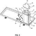
- FIG. 5 is a perspective view showing the bottom plate 18, the compressor 2, and the soundproofing materials 32 and 33 of the heat pump water-heater outdoor unit 10 of Embodiment 1.
- the heat pump water-heater outdoor unit 10 includes the soundproofing materials 32 and 33.
- the soundproofing material 32 at least partially covers the side surface of the compressor 2.
- the soundproofing material 32 covers the entire side surfaces of the compressor 2 and the suction muffler 25.
- the soundproofing material 32 becomes cylindrical by being wound around the compressor 2 and the suction muffler 25.
- the compressor 2 and the suction muffler 25 are positioned inside the cylindrical soundproofing material 32.
- the soundproofing material 33 covers the compressor 2 and the suction muffler 25 from above.
- the soundproofing material 33 is disposed so as to close an opening at the upper end of the cylindrical soundproofing material 32.
- holes 44 for passage of the suction pipe 26 and the discharge pipe 27 are formed. According to the present embodiment, by providing the soundproofing materials 32 and 33, it is possible to reliably suppress leakage of noise during the operation of the compressor 2 to the outside of the heat pump water-heater outdoor unit 10.
- Each of the soundproofing materials 32 and 33 includes a sound absorbing material.
- the sound absorbing material is made of a material having fine voids.
- the sound absorbing material may include at least one of, e.g., felt, glass wool, and rock wool.
- Each of the soundproofing materials 32 and 33 may further include a sound insulating material.
- the sound absorbing material may constitute an inner layer of each of the soundproofing materials 32 and 33, and the sound insulating material may constitute an outer layer of each of the soundproofing materials 32 and 33.
- the sound insulating material is made of a material having a density higher than that of the sound absorbing material.
- the sound insulating material may be formed of, e.g., a rubber material or a resin material.
- the drain hole 36 provided in the bottom plate 18 is clogged with a foreign object such as, e.g., dead leaves or mud, and the drain hole 36 may be thereby blocked.
- a foreign object such as, e.g., dead leaves or mud
- the evaporator 5 is constantly cooled during the operation of the heat pump water-heater outdoor unit 10. Consequently, the amount of condensed water generated on the surface of the evaporator 5 is large than that of an outdoor unit of an air conditioner. In the case where the drain hole 36 is blocked, there is a possibility that a large amount of drainage will collect on the bottom plate 18.
- the sound absorbing material of each of the soundproofing materials 32 and 33 has fine voids, and hence the sound absorbing material has water absorption properties. Assuming that the lower end of the soundproofing material 32 comes into contact with a pool of the drainage on the bottom plate 18, the sound absorbing material of the soundproofing material 32 absorbs water. The sound absorption performance of the sound absorbing material having absorbed water is degraded. In addition, the water absorbed in the sound absorbing material comes into contact with the compressor 2, and the compressor 2 may be thereby corroded. In order to avoid these harmful effects, it is necessary to reliably prevent the lower end of the soundproofing material 32 from coming into contact with the pool of the drainage on the bottom plate 18.
- the heat pump water-heater outdoor unit 10 of the present embodiment includes the soundproofing material placement portion 24 which retains the position of the lower end of the soundproofing material 32.
- the soundproofing material placement portion 24 is disposed on the bottom plate 18.
- the soundproofing material placement portion 24 is shaped such that part of the soundproofing material placement portion 24 extends along the corner portion 183 of the bottom plate 18. More specifically, the soundproofing material placement portion 24 has a first side 241 which is configured so as to extend along the side surface of the edge portion 182 of the bottom plate 18 on a right side surface side, and a second side 242 which is configured so as to extend along the side surface of the edge portion 182 of the bottom plate 18 on a front surface side.
- the soundproofing material placement portion 24 is disposed such that the first side 241 and the second side 242 are in contact with the edge portions 182 including the corner portion 183 of the bottom plate 18. According to such an arrangement, the corner portion 183 of the bottom plate 18 is covered with the soundproofing material placement portion 24.
- the soundproofing material placement portion 24 by providing the soundproofing material placement portion 24, the following effect can be obtained. Even in the case where the pool of the drainage has occurred on the bottom plate 18 due to the blockage of the drain hole 36, it is possible to reliably prevent the situation in which the pool of the drainage occurs at the corner portion 183 and the lower end of the soundproofing material 32 is soaked in the pool of the drainage. It is possible to reliably prevent water from being absorbed in the sound absorbing material of the soundproofing material 32. It is possible to reliably prevent the occurrence of harmful effects such as a harmful effect in which the sound absorption performance of the sound absorbing material of the soundproofing material 32 is degraded and a harmful effect in which the compressor 2 is corroded.
- FIG. 6 is a cross-sectional view of the compressor 2, the bottom plate 18, the soundproofing material placement portion 24, and the soundproofing materials 32 and 33 in Embodiment 1.
- FIG. 6 shows the appearance of the compressor 2 instead of the cross section thereof.
- an upper surface 243 of the soundproofing material placement portion 24 is at a position above the upper end of the edge portion 182 of the bottom plate 18. More specifically, when a height from the bottom surface 181 of the bottom plate 18 to the upper end of the edge portion 182 is h1 and a height from the bottom surface 181 of the bottom plate 18 to the upper surface 243 of the soundproofing material placement portion 24 is h2, the soundproofing material placement portion 24 and the bottom plate 18 are configured so as to satisfy h2 > h1.
- the upper surface 243 of the soundproofing material placement portion 24 is in contact with the lower end surface of the soundproofing material 32.
- FIG. 7 is a perspective view of the soundproofing material placement portion 24 before the soundproofing material placement portion 24 is mounted to the compressor 2 in Embodiment 1 when viewed from above.
- FIG. 8 is a perspective view of the soundproofing material placement portion 24 before the soundproofing material placement portion 24 is mounted to the compressor 2 in Embodiment 1 when viewed from below.
- FIG. 9 is a view obtained by viewing the internal structure of the heat pump water-heater outdoor unit 10 to which the soundproofing material placement portion 24 in Embodiment 1 is mounted through the upper surface.
- a concave drain flow path 244 is provided on the lower surface of the soundproofing material placement portion 24 .
- the drain flow path 244 has an inlet 245 and an outlet 246 which are opened on the sides of the side surfaces of the soundproofing material placement portion 24.
- the inlet 245 is opened on the evaporator side, and the outlet 246 is opened on the drain hole 36 side.
- the inlet 245 is opened more widely than the outlet 246.
- the drain flow path 244 by providing the drain flow path 244, the following effect can be obtained.
- the drainage having flowed down from the evaporator 5 passes through the drain flow path 244 from the inlet 245, flows out from the outlet 246, and is discharged to the drain hole 36.
- the inlet 245 is widely opened toward the evaporator 5, and hence it is easy to take in the drainage having flowed down from the evaporator 5.
- the outlet 246 is narrowly opened toward the drain hole 36, and hence it is possible to effectively prevent the drainage having flowed out from the outlet 246 from flowing to other areas.
- it is possible to increase the drainage efficiency of the drainage to reliably prevent the soundproofing material 32 from being soaked in the drainage.
- the soundproofing material placement portion 24 is disposed on the bottom plate 18 by using the vibration isolation members 29 as positioning members. As shown in FIG. 7 and FIG. 8 , the soundproofing material placement portion 24 does not have an annular shape but has an arc-like shape. More specifically, the soundproofing material placement portion 24 is disposed to surround two sides of a triangle of the compressor leg portion 30 to which the compressor 2 is fixed so as to arc. According to the present embodiment, by providing the arc-shaped soundproofing material placement portion 24, the following effect can be obtained. Even in a state in which the compressor 2 is fixed to the bottom plate 18, it is possible to install the soundproofing material placement portion 24 on the bottom plate 18. With this, it is possible to mount the soundproofing material placement portion 24 irrespective of assembly procedure.
Landscapes
- Engineering & Computer Science (AREA)
- Chemical & Material Sciences (AREA)
- Combustion & Propulsion (AREA)
- Mechanical Engineering (AREA)
- General Engineering & Computer Science (AREA)
- Physics & Mathematics (AREA)
- Thermal Sciences (AREA)
- Life Sciences & Earth Sciences (AREA)
- Sustainable Development (AREA)
- Heat-Pump Type And Storage Water Heaters (AREA)
- Other Air-Conditioning Systems (AREA)
Abstract
Description
- The present invention relates to a heat pump water-heater outdoor unit.
- A heat pump hot water supply system which uses heat of the air and is excellent in energy efficiency is widely used. In a heat pump water-heater outdoor unit of the heat pump hot water supply system, an evaporator which causes a refrigerant to absorb the heat of the air, a propeller fan which blows air to the evaporator, a compressor which compresses the refrigerant, and a water-refrigerant heat exchanger which heats water with the compressed refrigerant having high temperature and high pressure are mounted. In order to reduce noise generated during operation, the periphery of the compressor is covered with a soundproofing material. The compressor is installed on a bottom plate serving as a base of the heat pump water-heater outdoor unit. There are cases where water condensed on the surface of the evaporator flows down to the bottom plate and collects. Such water is referred to as "drainage". The soundproofing material includes a substance having water absorption properties such as, e.g., felt. When the soundproofing material absorbs the drainage, there is a possibility that the compressor will be corroded by water in the drainage. When the soundproofing material absorbs the drainage, there is a possibility that soundproofing properties of the soundproofing material will be degraded. It is preferable to prevent the soundproofing material from coming into contact with the drainage having collected on the bottom plate such that the soundproofing material does not absorb the drainage.
- An outdoor unit disclosed in PTL 1 described below is configured in the following manner. A soundproofing material covering the side surface of a compressor includes a sound absorbing material having water absorption properties. A bottom plate on which the compressor is installed has a soundproofing material placement portion on which the soundproofing material is placed, and a surrounding portion which is positioned around the soundproofing material placement portion and is formed integrally with the soundproofing material placement portion. The soundproofing material placement portion is at a position higher than that of the surrounding portion. With this configuration, even when drainage flows down and collects on the surrounding portion of the bottom plate, contact of the drainage with the soundproofing material placed on the soundproofing material placement portion is suppressed. With this, penetration of the drainage into the sound absorbing material is suppressed.
- [PTL 1] Japanese Patent Application Publication No.
2013-53827 - The outdoor unit in PTL 1 has the following problems. Depending on the situation of an installation environment such as a porch or a berm, there are cases where the outdoor unit is tilted toward the compressor and installed. In these cases, the drainage having flowed down to the bottom plate collects at a corner portion on the compressor side, and the soundproofing material may be thereby soaked in the drainage. When the soundproofing material absorbs water, a problem may arise in that a shell of the compressor is corroded, and a problem may arise in that the soundproofing properties of the soundproofing material are degraded.
- The present invention has been made in order to solve the above-described problems, and an object thereof is to provide a heat pump water-heater outdoor unit capable of preventing a soundproofing material which covers the side surface of a compressor from absorbing water having collected on a bottom plate irrespective of the situation of an installation environment.
- A heat pump water-heater outdoor unit according to the present invention includes: a bottom plate having a rectangular bottom surface; a compressor provided on the bottom plate, the compressor compressing a refrigerant; a soundproofing material configured to cover a side surface of the compressor; and a soundproofing material placement portion provided on the bottom plate, the soundproofing material placement portion holding a lower end of the soundproofing material at a position higher than the bottom surface. The soundproofing material placement portion is configured to cover corner portion that is closest to the compressor out of corner portions of the bottom plate.
- According to the heat pump water-heater outdoor unit of the present invention, one corner portion that is closest to the compressor out of corner portions of the bottom plate is covered with the soundproofing material placement portion. Consequently, it is possible to prevent the soundproofing material covering the side surface of the compressor from being soaked in drainage which collects at the corner portion. With this, it becomes possible to suppress corrosion of a shell of the compressor and degradation of soundproofing properties irrespective of the situation of the installation environment.
-
-
FIG. 1 is a view of piping of a heat pump hot water supply system including a heat pump water-heater outdoor unit of Embodiment 1. -
FIG. 2 is a perspective view showing the appearance of the heat pump water-heater outdoor unit of Embodiment 1. -
FIG. 3 is an exploded perspective view of the heat pump water-heater outdoor unit of Embodiment 1. -
FIG. 4 is an exploded perspective view showing a bottom plate and a compressor of the heat pump water-heater outdoor unit of Embodiment 1. -
FIG. 5 is a perspective view showing the bottom plate, the compressor, and a soundproofing material of the heat pump water-heater outdoor unit of Embodiment 1. -
FIG. 6 is a cross-sectional view of the compressor, the bottom plate, a soundproofing material placement portion, and the soundproofing material in Embodiment 1. -
FIG. 7 is a perspective view of the soundproofing material placement portion before the soundproofing material placement portion is mounted to the compressor in Embodiment 1 when viewed from above. -
FIG. 8 is a perspective view of the soundproofing material placement portion before the soundproofing material placement portion is mounted to the compressor in Embodiment 1 when viewed from below. -
FIG. 9 is a view obtained by viewing the internal structure of the heat pump water-heater outdoor unit to which the soundproofing material placement portion in Embodiment 1 is mounted through an upper surface. - Hereinbelow, an embodiment will be described with reference to the drawings. Common elements in the drawings are designated by the same reference numerals, and the duplicate description thereof will be simplified or omitted. In addition, the present disclosure may include any combinations of, among configurations described in the following embodiment, configurations which may be combined.
-
FIG. 1 is a view of piping of a heat pump hot water supply system including a heat pump water-heater outdoor unit of Embodiment 1. As shown inFIG. 1 , a heat pump hotwater supply system 100 includes a heat pump water-heateroutdoor unit 10, and atank unit 50. The heat pump water-heateroutdoor unit 10 is installed outdoors. Thetank unit 50 may be installed outdoors or may also be installed indoors. - The heat pump water-heater
outdoor unit 10 includes acompressor 2, a heat exchanger 3, afirst expansion valve 4a, asecond expansion valve 4b, anevaporator 5, aninternal heat exchanger 6, and afan 7. The heat pump water-heateroutdoor unit 10 includes a refrigerant circuit, and performs operation of a refrigeration cycle, i.e., a heat pump cycle. Thecompressor 2 compresses low-pressure refrigerant gas. A refrigerant may be, e.g., carbon dioxide. The heat exchanger 3 exchanges heat between a high-temperature high-pressure refrigerant discharged from thecompressor 2 and water or another liquid heating medium. The liquid heating medium may be, e.g., a calcium chloride aqueous solution, an ethylene glycol aqueous solution, or alcohol. - Each of the
first expansion valve 4a and thesecond expansion valve 4b is an example of a decompression device which decompresses a high-pressure refrigerant to change the high-pressure refrigerant into a low-pressure refrigerant. The decompressed low-pressure refrigerant is brought into a gas-liquid two-phase state. Theevaporator 5 is a heat exchanger which exchanges heat between the low-pressure refrigerant and the air. In theevaporator 5, the low-pressure refrigerant evaporates by absorbing heat of the air. Thefan 7 blows air to theevaporator 5, and heat exchange in theevaporator 5 can be thereby facilitated. Theinternal heat exchanger 6 includes a high-pressure flow path and a low-pressure flow path. Theinternal heat exchanger 6 exchanges heat between the high-pressure refrigerant flowing in the high-pressure flow path and the low-pressure refrigerant flowing in the low-pressure flow path. The low-pressure refrigerant gas evaporated in theevaporator 5 is sucked into thecompressor 2 via the low-pressure flow path of theinternal heat exchanger 6. - The refrigerant circuit in the present embodiment includes a
first channel 8 in which the refrigerant having passed through the heat exchanger 3 reaches theevaporator 5 via the high-pressure flow path of theinternal heat exchanger 6, and asecond channel 9 in which the refrigerant having passed through the heat exchanger 3 bypasses theinternal heat exchanger 6 and reaches theevaporator 5. Thefirst expansion valve 4a is installed in thefirst channel 8 on the downstream side of the high-pressure flow path of theinternal heat exchanger 6. Thesecond expansion valve 4b is installed in thesecond channel 9. By adjusting the openings of thefirst expansion valve 4a and thesecond expansion valve 4b, it is possible to change a ratio between the flow rate of the refrigerant which reaches theevaporator 5 from the heat exchanger 3 via theinternal heat exchanger 6 and the flow rate of the refrigerant which bypasses theinternal heat exchanger 6 and reaches theevaporator 5 from the heat exchanger 3. - The
tank unit 50 includes a hotwater storage tank 52, awater pump 53, a flowpath switching valve 54, and abypass flow path 55. The heat pump water-heateroutdoor unit 10 and thetank unit 50 are connected viaexternal pipings - In the hot
water storage tank 52, water before heating and hot water after heating are stored. In the hotwater storage tank 52, temperature stratification in which an upper side has high temperature and a lower side has low temperature is formed due to a difference in the specific gravity of water caused by temperature. To the upper portion of the hotwater storage tank 52, a hot water supply pipe (not shown) for supplying hot water to a terminal such as, e.g., a hot water faucet, a shower, or a bathtub is connected. To the lower portion of the hotwater storage tank 52, a water supply pipe (not shown) for supplying water from a water source such as a water supply is connected. When hot water is supplied from the hotwater storage tank 52, hot water in the upper portion of the hotwater storage tank 52 is sent to the hot water supply pipe by water pressure which is applied to the inside of the hotwater storage tank 52 from the water supply pipe. Water in an amount equal to that of hot water having flowed out to the hot water supply pipe flows into the hotwater storage tank 52 from the water supply pipe, and the hotwater storage tank 52 is thereby kept in a fully filled state. - The lower portion of the hot
water storage tank 52 is connected to an inlet of thewater pump 53 via a conduit. An outlet of thewater pump 53 is connected to the flowpath switching valve 54. The flowpath switching valve 54 is connected to a water inlet of the heat exchanger 3 of the heat pump water-heateroutdoor unit 10 via theexternal piping 56. - The heat pump hot
water supply system 100 can perform heat storage operation which accumulates hot water heated by the heat pump water-heateroutdoor unit 10 in the hotwater storage tank 52. During the heat storage operation, the following operation is performed. Thecompressor 2, thefan 7, and thewater pump 53 are operated. Water having flowed out from the lower portion of the hotwater storage tank 52 flows into the heat exchanger 3 of the heat pump water-heateroutdoor unit 10 through thewater pump 53, the flowpath switching valve 54, and theexternal piping 56. The water is heated by the refrigerant in the heat exchanger 3 and becomes hot water. The temperature of hot water heated in the heat exchanger 3 may be, e.g., about 65°C to about 90°C. Hot water having flowed out from the heat exchanger 3 returns to thetank unit 50 through theexternal piping 57, and flows into the upper portion of the hotwater storage tank 52 through a tankupper pipe 58. - The flow
path switching valve 54 can switch the flow path such that water discharged from thewater pump 53 is caused to pass through thebypass flow path 55 instead of the heat pump water-heateroutdoor unit 10, and flow into the tankupper pipe 58. - The heat pump water-heater outdoor unit of the present invention is not limited to the heat pump water-heater outdoor unit constituting part of a hot water supply system such as the above-described heat pump hot
water supply system 100, and may also be the heat pump water-heater outdoor unit which is used for the purpose of heating the liquid heating medium in, e.g., a hot-water heating system. That is, the liquid heating medium heated by the heat pump water-heater outdoor unit of the present invention may be supplied to an indoor heating appliance such as, e.g., a floor heating panel which is installed under a floor, a radiator or a panel heater which is installed on an indoor wall surface, or a fan convector. -
FIG. 2 is a perspective view showing the appearance of the heat pump water-heateroutdoor unit 10 of Embodiment 1.FIG. 3 is an exploded perspective view of the heat pump water-heateroutdoor unit 10 of Embodiment 1. As shown inFIG. 2 , the heat pump water-heateroutdoor unit 10 includes a plurality ofleg portions 41. Theleg portions 41 are fixed to the ground or a floor surface. - As shown in
FIG. 3 , the heat pump water-heateroutdoor unit 10 includes abottom plate 18, afront panel 19, aside panel 20, and atop panel 21. Thebottom plate 18, thefront panel 19, theside panel 20, and thetop panel 21 constitute an outer shell, i.e., a cabinet of the heat pump water-heateroutdoor unit 10. Thebottom plate 18, thefront panel 19, theside panel 20, and thetop panel 21 are preferably made of metal. Thebottom plate 18 corresponds to a base or a frame of the heat pump water-heateroutdoor unit 10. Constituent devices such as thecompressor 2 are mounted on thebottom plate 18. Theleg portions 41 are fixed to the lower surface of thebottom plate 18. - The
front panel 19 covers the front surface and the left side surface of the heat pump water-heateroutdoor unit 10. Theside panel 20 covers part of the rear surface and the right side surface of the heat pump water-heateroutdoor unit 10. Thetop panel 21 covers the upper surface of the heat pump water-heateroutdoor unit 10. - The
evaporator 5 is disposed so as to cover the rear surface and the left side surface of the heat pump water-heateroutdoor unit 10. Thefan 7 is disposed between theevaporator 5 and thefront panel 19. Thefan 7 in the present embodiment includes a propeller fan. The internal portion of the outer shell of the heat pump water-heateroutdoor unit 10 is partitioned into afan room 15 in which thefan 7 is disposed and amachine room 14. Thefan room 15 is separated from themachine room 14 by apartition plate 16. Thecompressor 2 and refrigerant piping are disposed in themachine room 14. InFIG. 3 , depiction ofsoundproofing materials case 13 is disposed below thefan 7. The heat exchanger 3 is stored in thecase 13 in a state in which the heat exchanger 3 is covered with a heat insulating material. - The
front panel 19 has an opening at a position which faces thefan 7. Agrille 23 which covers the opening is mounted to thefront panel 19. When thefan 7 is operated, outside air, i.e., the air flows into thefan room 15 through theevaporator 5, and is discharged to the outside of the heat pump water-heateroutdoor unit 10 from thegrille 23. - The heat pump water-heater
outdoor unit 10 includes an electricalcomponent storage box 17. The electricalcomponent storage box 17 is disposed in space which occupies part of the upper portion of thefan room 15 and the upper portion of themachine room 14. In the electricalcomponent storage box 17, an electrical component such as, e.g., an inverter power supply which drives and controls a motor of thecompressor 2 and a motor of thefan 7 is stored. A terminal block is provided near the electricalcomponent storage box 17. The terminal block is used when external electrical wiring is connected. Aservice panel 22 is detachably attached to theside panel 20. Theservice panel 22 protects the terminal block. Aconnection portion cover 42 is detachably attached to theside panel 20 below theservice panel 22. Theconnection portion cover 42 protects a connection portion (not shown) to which theexternal pipings -
FIG. 4 is an exploded perspective view showing thebottom plate 18 and thecompressor 2 of the heat pump water-heateroutdoor unit 10 of Embodiment 1. As shown inFIG. 4 , thebottom plate 18 has a shape in which a plurality of projections and depressions, stepped portions, and slopes which have height differences of, e.g., about 1 cm are formed. Thebottom plate 18 has arectangular bottom surface 181, and anedge portion 182 which extends upward from each side of thebottom surface 181. Thebottom plate 18 may be formed by press working such as, e.g., drawing. Thebottom plate 18 has water shielding properties. - In the
bottom plate 18, a plurality of (two in the present embodiment) drain holes 36 for discharging drainage are formed. It is preferable that thedrain hole 36 is provided at the lowest position in thebottom plate 18. The number of drain holes 36 may be two or more. The temperature of theevaporator 5 becomes low during the operation of the heat pump water-heateroutdoor unit 10, and hence there are cases where water contained in air passing through theevaporator 5 is condensed on the surface of theevaporator 5. The condensed drainage flows down due to gravity. Thebottom plate 18 receives the drainage. The drainage flows toward the position of thedrain hole 36 with the height differences formed in thebottom plate 18, and is discharged from thedrain hole 36 to space below thebottom plate 18. - The
compressor 2 includes a shell. The shape of the shell may be a cylindrical shape shown in the drawing. A compression device which compresses the refrigerant and a motor which drives the compression device are stored inside the shell of thecompressor 2, through the depiction thereof is omitted. The compression device may be any of, e.g., reciprocation-type, scroll-type, and rotary-type compression devices. - A suction muffler 25 is positioned adjacent to the shell of the
compressor 2. The suction muffler 25 is coupled to the side surface of the shell of thecompressor 2. The shape of the suction muffler 25 may be a cylindrical shape smaller than that of the shell of thecompressor 2. Asuction pipe 26 is connected to the suction muffler 25. Low-pressure refrigerant gas is sucked into thecompressor 2 through thesuction pipe 26 and the suction muffler 25. Adischarge pipe 27 is connected to thecompressor 2. High-pressure refrigerant gas compressed in thecompressor 2 is discharged to thedischarge pipe 27. - A
compressor leg portion 30 is fixed to the bottom portion of the shell of thecompressor 2. Thecompressor 2 is mounted on thebottom plate 18 via thecompressor leg portion 30. Thecompressor leg portion 30 has a strength which allows thecompressor leg portion 30 to support the weight of thecompressor 2 and the suction muffler 25. Thecompressor leg portion 30 is preferably made of metal. Thecompressor leg portion 30 corresponds to a base portion which supports thecompressor 2. Thecompressor leg portion 30 in the embodiment is a plate-like member. The upper surface of thecompressor leg portion 30 is joined to the bottom surface of the shell of thecompressor 2. Thecompressor leg portion 30 may be welded to the shell of thecompressor 2. A plurality of (three in the present embodiment) holes 43 are formed in thecompressor leg portion 30. - A plurality of (three in the present embodiment)
bolts 28 for coupling thecompressor 2 to thebottom plate 18 are installed on thebottom plate 18. Eachbolt 28 protrudes upward. Thebolt 28 may also be a weld bolt which is welded to the upper surface of thebottom plate 18. The heat pump water-heateroutdoor unit 10 includes a plurality of (three in the present embodiment)vibration isolation members 29. Eachvibration isolation member 29 is disposed between the upper surface of thebottom plate 18 and the lower surface of thecompressor leg portion 30. Thevibration isolation member 29 is a member having elasticity such as, e.g., rubber or a spring. The shape of thevibration isolation member 29 may be a cylindrical shape shown in the drawing or a columnar shape. Thevibration isolation member 29 has a hole through which thebolt 28 can pass. Thebolt 28 passes through the hole of thevibration isolation member 29 and thehole 43 of thecompressor leg portion 30. Anut 31 is screwed on thebolt 28. Thevibration isolation member 29 and thecompressor leg portion 30 are held between thebottom plate 18 and thenut 31, and thecompressor 2 is thereby coupled to thebottom plate 18. On thebottom plate 18, a soundproofingmaterial placement portion 24 is disposed so as to surround the periphery of thecompressor leg portion 30. The configuration of the soundproofingmaterial placement portion 24 and the function thereof will be described later in detail. - During the operation of the
compressor 2, vibration is generated by torque fluctuation of a rotator inside thecompressor 2, unbalance of the rotator, and pulsation of refrigerant pressure. Particularly in thecompressor 2 of the heat pump water-heateroutdoor unit 10, high compression pressure is required, and hence the vibration of thecompressor 2 tends to be increased. According to the present embodiment, the weight of thecompressor 2 and the suction muffler 25 is applied to thebottom plate 18 via thevibration isolation member 29. Thevibration isolation member 29 absorbs the vibration during the operation of thecompressor 2, whereby it is possible to reliably suppress the transmission of the vibration of thecompressor 2 to thebottom plate 18. - Assuming that the
vibration isolation member 29 is not provided and thecompressor 2 is directly fixed to the upper surface of thebottom plate 18, the following problem arises. The vibration of thecompressor 2 is transmitted to thebottom plate 18, and the vibration of thebottom plate 18 is further transmitted to thefront panel 19, theside panel 20, thetop panel 21, thepartition plate 16, and theevaporator 5. As a result, there is a possibility that the vibrations of thebottom plate 18, thefront panel 19, theside panel 20, thetop panel 21, thepartition plate 16, and theevaporator 5 will generate noise, particularly low-frequency noise. The low-frequency noise is sound including low frequency which cannot be perceived by the sense of hearing of a human being. - According to the present embodiment, by providing the
vibration isolation member 29, it is possible to reduce the vibrations of thebottom plate 18, thefront panel 19, theside panel 20, thetop panel 21, thepartition plate 16, and theevaporator 5. Therefore, it is possible to reliably suppress generation of noise, particularly low-frequency noise. -
FIG. 5 is a perspective view showing thebottom plate 18, thecompressor 2, and thesoundproofing materials outdoor unit 10 of Embodiment 1. As shown inFIG. 5 , the heat pump water-heateroutdoor unit 10 includes thesoundproofing materials material 32 at least partially covers the side surface of thecompressor 2. In the present embodiment, the soundproofingmaterial 32 covers the entire side surfaces of thecompressor 2 and the suction muffler 25. The soundproofingmaterial 32 becomes cylindrical by being wound around thecompressor 2 and the suction muffler 25. Thecompressor 2 and the suction muffler 25 are positioned inside thecylindrical soundproofing material 32. The soundproofingmaterial 33 covers thecompressor 2 and the suction muffler 25 from above. The soundproofingmaterial 33 is disposed so as to close an opening at the upper end of thecylindrical soundproofing material 32. In the soundproofingmaterial 33, holes 44 for passage of thesuction pipe 26 and thedischarge pipe 27 are formed. According to the present embodiment, by providing thesoundproofing materials compressor 2 to the outside of the heat pump water-heateroutdoor unit 10. - Each of the
soundproofing materials soundproofing materials soundproofing materials soundproofing materials - The
drain hole 36 provided in thebottom plate 18 is clogged with a foreign object such as, e.g., dead leaves or mud, and thedrain hole 36 may be thereby blocked. In the case where thedrain hole 36 is blocked, water having flowed down from theevaporator 5 or the like is not discharged from thedrain hole 36. Theevaporator 5 is constantly cooled during the operation of the heat pump water-heateroutdoor unit 10. Consequently, the amount of condensed water generated on the surface of theevaporator 5 is large than that of an outdoor unit of an air conditioner. In the case where thedrain hole 36 is blocked, there is a possibility that a large amount of drainage will collect on thebottom plate 18. - Depending on the situation of an installation environment such as a porch or a berm, there are cases where the heat pump water-heater
outdoor unit 10 is installed in a state in which the heat pump water-heateroutdoor unit 10 is tilted toward thecompressor 2. In these cases, there is a possibility that a large amount of drainage will collect on thebottom plate 18, particularly in an area in the vicinity of acorner portion 183 closest to thecompressor 2. - The sound absorbing material of each of the
soundproofing materials material 32 comes into contact with a pool of the drainage on thebottom plate 18, the sound absorbing material of the soundproofingmaterial 32 absorbs water. The sound absorption performance of the sound absorbing material having absorbed water is degraded. In addition, the water absorbed in the sound absorbing material comes into contact with thecompressor 2, and thecompressor 2 may be thereby corroded. In order to avoid these harmful effects, it is necessary to reliably prevent the lower end of the soundproofingmaterial 32 from coming into contact with the pool of the drainage on thebottom plate 18. - As shown in
FIG. 4 andFIG. 5 , the heat pump water-heateroutdoor unit 10 of the present embodiment includes the soundproofingmaterial placement portion 24 which retains the position of the lower end of the soundproofingmaterial 32. The soundproofingmaterial placement portion 24 is disposed on thebottom plate 18. The soundproofingmaterial placement portion 24 is shaped such that part of the soundproofingmaterial placement portion 24 extends along thecorner portion 183 of thebottom plate 18. More specifically, the soundproofingmaterial placement portion 24 has afirst side 241 which is configured so as to extend along the side surface of theedge portion 182 of thebottom plate 18 on a right side surface side, and asecond side 242 which is configured so as to extend along the side surface of theedge portion 182 of thebottom plate 18 on a front surface side. An angle formed between thefirst side 241 and thesecond side 242 is 90 degrees. The soundproofingmaterial placement portion 24 is disposed such that thefirst side 241 and thesecond side 242 are in contact with theedge portions 182 including thecorner portion 183 of thebottom plate 18. According to such an arrangement, thecorner portion 183 of thebottom plate 18 is covered with the soundproofingmaterial placement portion 24. - According to the present embodiment, by providing the soundproofing
material placement portion 24, the following effect can be obtained. Even in the case where the pool of the drainage has occurred on thebottom plate 18 due to the blockage of thedrain hole 36, it is possible to reliably prevent the situation in which the pool of the drainage occurs at thecorner portion 183 and the lower end of the soundproofingmaterial 32 is soaked in the pool of the drainage. It is possible to reliably prevent water from being absorbed in the sound absorbing material of the soundproofingmaterial 32. It is possible to reliably prevent the occurrence of harmful effects such as a harmful effect in which the sound absorption performance of the sound absorbing material of the soundproofingmaterial 32 is degraded and a harmful effect in which thecompressor 2 is corroded. -
FIG. 6 is a cross-sectional view of thecompressor 2, thebottom plate 18, the soundproofingmaterial placement portion 24, and thesoundproofing materials FIG. 6 shows the appearance of thecompressor 2 instead of the cross section thereof. - As shown in
FIG. 6 , anupper surface 243 of the soundproofingmaterial placement portion 24 is at a position above the upper end of theedge portion 182 of thebottom plate 18. More specifically, when a height from thebottom surface 181 of thebottom plate 18 to the upper end of theedge portion 182 is h1 and a height from thebottom surface 181 of thebottom plate 18 to theupper surface 243 of the soundproofingmaterial placement portion 24 is h2, the soundproofingmaterial placement portion 24 and thebottom plate 18 are configured so as to satisfy h2 > h1. Theupper surface 243 of the soundproofingmaterial placement portion 24 is in contact with the lower end surface of the soundproofingmaterial 32. Even when drainage W collects at thecorner portion 183 of thebottom plate 18, the surface thereof does not become higher than the height h1 of theedge portion 182. According to the configuration of the present embodiment, it is possible to reliably hold the lower end surface of the soundproofingmaterial 32 at the position above the surface of the pool of the drainage. Accordingly, even in the case where the pool of the drainage has occurred on thebottom plate 18 when thedrain hole 36 is blocked, it is possible to reliably prevent the lower end of the soundproofingmaterial 32 from coming into contact with the pool of the drainage, and reliably prevent the sound absorbing material of the soundproofingmaterial 32 from absorbing water. -
FIG. 7 is a perspective view of the soundproofingmaterial placement portion 24 before the soundproofingmaterial placement portion 24 is mounted to thecompressor 2 in Embodiment 1 when viewed from above. In addition,FIG. 8 is a perspective view of the soundproofingmaterial placement portion 24 before the soundproofingmaterial placement portion 24 is mounted to thecompressor 2 in Embodiment 1 when viewed from below. Further,FIG. 9 is a view obtained by viewing the internal structure of the heat pump water-heateroutdoor unit 10 to which the soundproofingmaterial placement portion 24 in Embodiment 1 is mounted through the upper surface. - As shown in
FIG. 7 and FIG. 8 , on the lower surface of the soundproofingmaterial placement portion 24, a concavedrain flow path 244 is provided. Thedrain flow path 244 has aninlet 245 and anoutlet 246 which are opened on the sides of the side surfaces of the soundproofingmaterial placement portion 24. As shown inFIG. 8 andFIG. 9 , in the soundproofingmaterial placement portion 24, theinlet 245 is opened on the evaporator side, and theoutlet 246 is opened on thedrain hole 36 side. Theinlet 245 is opened more widely than theoutlet 246. - According to the present embodiment, by providing the
drain flow path 244, the following effect can be obtained. As shown inFIG. 9 , the drainage having flowed down from theevaporator 5 passes through thedrain flow path 244 from theinlet 245, flows out from theoutlet 246, and is discharged to thedrain hole 36. With this, it is possible to prevent the drainage from collecting at thecorner portion 183 of thebottom plate 18. Theinlet 245 is widely opened toward theevaporator 5, and hence it is easy to take in the drainage having flowed down from theevaporator 5. In addition, theoutlet 246 is narrowly opened toward thedrain hole 36, and hence it is possible to effectively prevent the drainage having flowed out from theoutlet 246 from flowing to other areas. Thus, according to the present embodiment, it is possible to increase the drainage efficiency of the drainage to reliably prevent thesoundproofing material 32 from being soaked in the drainage. - Note that the soundproofing
material placement portion 24 is disposed on thebottom plate 18 by using thevibration isolation members 29 as positioning members. As shown inFIG. 7 and FIG. 8 , the soundproofingmaterial placement portion 24 does not have an annular shape but has an arc-like shape. More specifically, the soundproofingmaterial placement portion 24 is disposed to surround two sides of a triangle of thecompressor leg portion 30 to which thecompressor 2 is fixed so as to arc. According to the present embodiment, by providing the arc-shaped soundproofingmaterial placement portion 24, the following effect can be obtained. Even in a state in which thecompressor 2 is fixed to thebottom plate 18, it is possible to install the soundproofingmaterial placement portion 24 on thebottom plate 18. With this, it is possible to mount the soundproofingmaterial placement portion 24 irrespective of assembly procedure. -
- 2
- Compressor
- 3
- Heat exchanger
- 4a
- First expansion valve
- 4b
- Second expansion valve
- 5
- Evaporator
- 6
- Internal heat exchanger
- 7
- Fan
- 8
- First channel
- 9
- Second channel
- 10
- Heat pump water-heater outdoor unit
- 13
- Case
- 14
- Machine room
- 15
- Fan room
- 16
- Partition plate
- 17
- Electrical component storage box
- 18
- Bottom plate
- 181
- Bottom surface
- 182
- Edge portion
- 183
- Corner portion
- 19
- Front panel
- 20
- Side panel
- 21
- Top panel
- 22
- Service panel
- 23
- Grille
- 24
- Soundproofing material placement portion
- 241
- First side
- 242
- Second side
- 243
- Upper surface
- 244
- Drain flow path
- 245
- Inlet
- 246
- Outlet
- 25
- Suction muffler
- 26
- Suction pipe
- 27
- Discharge pipe
- 28
- Bolt
- 29
- Vibration isolation member
- 30
- Compressor leg portion
- 31
- Nut
- 32, 33
- Soundproofing material
- 36
- Drain hole
- 41
- Leg portion
- 42
- Connection portion cover
- 43
- Hole
- 44
- Hole
- 50
- Tank unit
- 52
- Hot water storage tank
- 53
- Water pump
- 54
- Flow path switching valve
- 55
- Bypass flow path
- 56, 57
- External piping
- 58
- Tank upper pipe
- 100
- Heat pump hot water supply system
Claims (6)
- A heat pump water-heater outdoor unit comprising:a bottom plate having a rectangular bottom surface;a compressor provided on the bottom plate, the compressor compressing a refrigerant;a soundproofing material covering a side surface of the compressor; anda soundproofing material placement portion provided on the bottom plate, the soundproofing material placement portion holding a lower end of the soundproofing material at a position higher than the bottom surface,wherein the soundproofing material placement portion is configured to cover one corner portion that is closest to the compressor out of corner portions of the bottom plate.
- The heat pump water-heater outdoor unit according to claim 1,
wherein the bottom plate includes an edge portion which extends upward from each side of the bottom surface, and
wherein the soundproofing material placement portion is configured to hold the lower end of the soundproofing material at a position higher than an upper end of the edge portion. - The heat pump water-heater outdoor unit according to claim 1 or 2,
wherein a drain flow path for allowing drainage to flow is formed on a lower surface of the soundproofing material placement portion facing the bottom surface. - The heat pump water-heater outdoor unit according to claim 3,
wherein an evaporator is disposed on a rear surface side of the heat pump water-heater outdoor unit,
wherein a drain hole for discharging the drainage is formed in the bottom surface, and
wherein the soundproofing material placement portion is configured such that an inlet of the drain flow path is opened toward the evaporator, and an outlet of the drain flow path is opened toward the drain hole. - The heat pump water-heater outdoor unit according to claim 4,
wherein the soundproofing material placement portion is configured such that an opening of the inlet is larger than an opening of the outlet. - The heat pump water-heater outdoor unit according to any one of claims 1 to 5,
wherein the soundproofing material placement portion is configured to surround a periphery of the compressor so as to arc, and
wherein the heat pump water-heater outdoor unit is configured such that the soundproofing material placement portion is placeable on the bottom plate in a state in which the compressor is disposed on the bottom plate.
Applications Claiming Priority (1)
| Application Number | Priority Date | Filing Date | Title |
|---|---|---|---|
| PCT/JP2018/001994 WO2019146003A1 (en) | 2018-01-23 | 2018-01-23 | Heat pump hot water supply outdoor unit |
Publications (3)
| Publication Number | Publication Date |
|---|---|
| EP3745033A1 true EP3745033A1 (en) | 2020-12-02 |
| EP3745033A4 EP3745033A4 (en) | 2021-01-06 |
| EP3745033B1 EP3745033B1 (en) | 2023-08-09 |
Family
ID=67394906
Family Applications (1)
| Application Number | Title | Priority Date | Filing Date |
|---|---|---|---|
| EP18902846.7A Active EP3745033B1 (en) | 2018-01-23 | 2018-01-23 | Heat pump hot water supply outdoor unit |
Country Status (3)
| Country | Link |
|---|---|
| EP (1) | EP3745033B1 (en) |
| JP (1) | JP6747614B2 (en) |
| WO (1) | WO2019146003A1 (en) |
Cited By (4)
| Publication number | Priority date | Publication date | Assignee | Title |
|---|---|---|---|---|
| CN110779210A (en) * | 2019-11-13 | 2020-02-11 | 江苏浴普太阳能有限公司 | Air can hot water ware chassis device |
| WO2022184208A1 (en) * | 2021-03-01 | 2022-09-09 | Viessmann Climate Solutions Se | Heat pump |
| DE102021205746A1 (en) | 2021-06-08 | 2022-12-08 | Robert Bosch Gesellschaft Für Medizinische Forschung Mbh | Heat pump with a floor stand |
| WO2023137173A1 (en) * | 2022-01-14 | 2023-07-20 | Rheem Manufacturing Company | Shroud structure |
Families Citing this family (4)
| Publication number | Priority date | Publication date | Assignee | Title |
|---|---|---|---|---|
| JP2023052717A (en) * | 2020-03-16 | 2023-04-12 | 株式会社富士通ゼネラル | air conditioner |
| DE102020112799A1 (en) * | 2020-05-12 | 2021-11-18 | Viessmann Werke Gmbh & Co Kg | Heat pump system |
| JP7223723B2 (en) * | 2020-05-28 | 2023-02-16 | 日立グローバルライフソリューションズ株式会社 | heat pump water heater |
| WO2022168261A1 (en) * | 2021-02-05 | 2022-08-11 | 三菱電機株式会社 | Compressor corrosion diagnosis device and compressor corrosion diagnosis method |
Family Cites Families (8)
| Publication number | Priority date | Publication date | Assignee | Title |
|---|---|---|---|---|
| US4982812A (en) * | 1989-10-24 | 1991-01-08 | Hwang Min Su | Noise-preventive means for compressor used in air conditioner |
| JPH0719531A (en) * | 1993-07-07 | 1995-01-20 | Toshiba Corp | Air conditioner outdoor unit |
| JP2005241197A (en) * | 2004-02-27 | 2005-09-08 | Kimura Kohki Co Ltd | Heat pump air conditioner |
| JP5146525B2 (en) * | 2010-12-24 | 2013-02-20 | 三菱電機株式会社 | Heat pump type heat source unit |
| JP2013053771A (en) * | 2011-09-01 | 2013-03-21 | Daikin Industries Ltd | Outdoor unit |
| JP2013053827A (en) | 2011-09-06 | 2013-03-21 | Daikin Industries Ltd | Outdoor unit |
| JP2013068386A (en) * | 2011-09-26 | 2013-04-18 | Daikin Industries Ltd | Outdoor unit |
| JP2013088003A (en) * | 2011-10-17 | 2013-05-13 | Daikin Industries Ltd | Outdoor unit |
-
2018
- 2018-01-23 JP JP2019567433A patent/JP6747614B2/en active Active
- 2018-01-23 EP EP18902846.7A patent/EP3745033B1/en active Active
- 2018-01-23 WO PCT/JP2018/001994 patent/WO2019146003A1/en not_active Ceased
Cited By (7)
| Publication number | Priority date | Publication date | Assignee | Title |
|---|---|---|---|---|
| CN110779210A (en) * | 2019-11-13 | 2020-02-11 | 江苏浴普太阳能有限公司 | Air can hot water ware chassis device |
| WO2022184208A1 (en) * | 2021-03-01 | 2022-09-09 | Viessmann Climate Solutions Se | Heat pump |
| CN116964391A (en) * | 2021-03-01 | 2023-10-27 | 菲斯曼气候解决方案欧洲股份公司 | heat pump |
| US12313286B2 (en) | 2021-03-01 | 2025-05-27 | Viessmann Climate Solutions Se | Heat pump |
| CN116964391B (en) * | 2021-03-01 | 2026-02-27 | 菲斯曼气候解决方案欧洲股份公司 | heat pump |
| DE102021205746A1 (en) | 2021-06-08 | 2022-12-08 | Robert Bosch Gesellschaft Für Medizinische Forschung Mbh | Heat pump with a floor stand |
| WO2023137173A1 (en) * | 2022-01-14 | 2023-07-20 | Rheem Manufacturing Company | Shroud structure |
Also Published As
| Publication number | Publication date |
|---|---|
| NZ764215A (en) | 2024-08-30 |
| JP6747614B2 (en) | 2020-08-26 |
| EP3745033B1 (en) | 2023-08-09 |
| EP3745033A4 (en) | 2021-01-06 |
| WO2019146003A1 (en) | 2019-08-01 |
| JPWO2019146003A1 (en) | 2020-04-30 |
Similar Documents
| Publication | Publication Date | Title |
|---|---|---|
| EP3745033B1 (en) | Heat pump hot water supply outdoor unit | |
| JP5287614B2 (en) | Heat pump outdoor unit | |
| JP6980104B2 (en) | Geothermal heat pump system | |
| EP3760936A1 (en) | Air conditioning device | |
| JP6921326B2 (en) | Heat pump hot water supply outdoor unit | |
| EP1959204B1 (en) | Air/water heat exchange apparatus | |
| JP6631706B2 (en) | Heat pump hot water outdoor unit | |
| JP6841350B2 (en) | Heat pump hot water supply outdoor unit | |
| WO2022003869A1 (en) | Outdoor unit and air conditioning device using same | |
| JP5880123B2 (en) | Heat pump outdoor unit | |
| CN215175535U (en) | A window air conditioner | |
| JPWO2018109846A1 (en) | Heat pump water heater outdoor unit | |
| JP2014031902A (en) | Heat pump hot water supply outdoor unit | |
| JP6635202B2 (en) | Heat pump equipment | |
| JP5630427B2 (en) | Heat pump water heater outdoor unit | |
| JP7841055B1 (en) | Outdoor unit and heat pump system equipped therewith | |
| JP6798628B2 (en) | Heat pump device | |
| CN224003923U (en) | heat pump water heater | |
| CN219014475U (en) | Integral shelter air conditioner | |
| JP6669306B2 (en) | Heat pump equipment | |
| JP2021012008A (en) | Outdoor unit of refrigeration equipment | |
| JP2004251587A (en) | Outdoor unit of air conditioner | |
| JP2023153086A (en) | Refrigeration cycle device | |
| KR20090027354A (en) | Leakage prevention structure of drain hose connection part of air conditioner | |
| JP2791711B2 (en) | Air conditioner |
Legal Events
| Date | Code | Title | Description |
|---|---|---|---|
| STAA | Information on the status of an ep patent application or granted ep patent |
Free format text: STATUS: THE INTERNATIONAL PUBLICATION HAS BEEN MADE |
|
| PUAI | Public reference made under article 153(3) epc to a published international application that has entered the european phase |
Free format text: ORIGINAL CODE: 0009012 |
|
| STAA | Information on the status of an ep patent application or granted ep patent |
Free format text: STATUS: REQUEST FOR EXAMINATION WAS MADE |
|
| 17P | Request for examination filed |
Effective date: 20200228 |
|
| AK | Designated contracting states |
Kind code of ref document: A1 Designated state(s): AL AT BE BG CH CY CZ DE DK EE ES FI FR GB GR HR HU IE IS IT LI LT LU LV MC MK MT NL NO PL PT RO RS SE SI SK SM TR |
|
| AX | Request for extension of the european patent |
Extension state: BA ME |
|
| A4 | Supplementary search report drawn up and despatched |
Effective date: 20201203 |
|
| RIC1 | Information provided on ipc code assigned before grant |
Ipc: F24F 1/36 20110101ALI20201127BHEP Ipc: F24F 5/00 20060101ALI20201127BHEP Ipc: F24F 13/24 20060101ALI20201127BHEP Ipc: F24D 17/02 20060101ALI20201127BHEP Ipc: F24F 1/10 20110101AFI20201127BHEP Ipc: F24F 1/12 20110101ALI20201127BHEP |
|
| DAV | Request for validation of the european patent (deleted) | ||
| DAX | Request for extension of the european patent (deleted) | ||
| REG | Reference to a national code |
Ref country code: DE Ref legal event code: R079 Free format text: PREVIOUS MAIN CLASS: F24F0001120000 Ipc: F24F0001100000 Ref document number: 602018055254 Country of ref document: DE |
|
| GRAP | Despatch of communication of intention to grant a patent |
Free format text: ORIGINAL CODE: EPIDOSNIGR1 |
|
| STAA | Information on the status of an ep patent application or granted ep patent |
Free format text: STATUS: GRANT OF PATENT IS INTENDED |
|
| RIC1 | Information provided on ipc code assigned before grant |
Ipc: F24F 1/36 20110101ALI20230301BHEP Ipc: F24F 13/24 20060101ALI20230301BHEP Ipc: F24F 5/00 20060101ALI20230301BHEP Ipc: F24D 17/02 20060101ALI20230301BHEP Ipc: F24F 1/12 20110101ALI20230301BHEP Ipc: F24F 1/10 20110101AFI20230301BHEP |
|
| INTG | Intention to grant announced |
Effective date: 20230320 |
|
| GRAS | Grant fee paid |
Free format text: ORIGINAL CODE: EPIDOSNIGR3 |
|
| GRAA | (expected) grant |
Free format text: ORIGINAL CODE: 0009210 |
|
| STAA | Information on the status of an ep patent application or granted ep patent |
Free format text: STATUS: THE PATENT HAS BEEN GRANTED |
|
| AK | Designated contracting states |
Kind code of ref document: B1 Designated state(s): AL AT BE BG CH CY CZ DE DK EE ES FI FR GB GR HR HU IE IS IT LI LT LU LV MC MK MT NL NO PL PT RO RS SE SI SK SM TR |
|
| REG | Reference to a national code |
Ref country code: GB Ref legal event code: FG4D |
|
| REG | Reference to a national code |
Ref country code: CH Ref legal event code: EP |
|
| P01 | Opt-out of the competence of the unified patent court (upc) registered |
Effective date: 20230719 |
|
| REG | Reference to a national code |
Ref country code: IE Ref legal event code: FG4D |
|
| REG | Reference to a national code |
Ref country code: DE Ref legal event code: R096 Ref document number: 602018055254 Country of ref document: DE |
|
| REG | Reference to a national code |
Ref country code: LT Ref legal event code: MG9D |
|
| REG | Reference to a national code |
Ref country code: NL Ref legal event code: MP Effective date: 20230809 |
|
| REG | Reference to a national code |
Ref country code: AT Ref legal event code: MK05 Ref document number: 1597934 Country of ref document: AT Kind code of ref document: T Effective date: 20230809 |
|
| PG25 | Lapsed in a contracting state [announced via postgrant information from national office to epo] |
Ref country code: GR Free format text: LAPSE BECAUSE OF FAILURE TO SUBMIT A TRANSLATION OF THE DESCRIPTION OR TO PAY THE FEE WITHIN THE PRESCRIBED TIME-LIMIT Effective date: 20231110 |
|
| PG25 | Lapsed in a contracting state [announced via postgrant information from national office to epo] |
Ref country code: IS Free format text: LAPSE BECAUSE OF FAILURE TO SUBMIT A TRANSLATION OF THE DESCRIPTION OR TO PAY THE FEE WITHIN THE PRESCRIBED TIME-LIMIT Effective date: 20231209 |
|
| PG25 | Lapsed in a contracting state [announced via postgrant information from national office to epo] |
Ref country code: SE Free format text: LAPSE BECAUSE OF FAILURE TO SUBMIT A TRANSLATION OF THE DESCRIPTION OR TO PAY THE FEE WITHIN THE PRESCRIBED TIME-LIMIT Effective date: 20230809 Ref country code: RS Free format text: LAPSE BECAUSE OF FAILURE TO SUBMIT A TRANSLATION OF THE DESCRIPTION OR TO PAY THE FEE WITHIN THE PRESCRIBED TIME-LIMIT Effective date: 20230809 Ref country code: PT Free format text: LAPSE BECAUSE OF FAILURE TO SUBMIT A TRANSLATION OF THE DESCRIPTION OR TO PAY THE FEE WITHIN THE PRESCRIBED TIME-LIMIT Effective date: 20231211 Ref country code: NO Free format text: LAPSE BECAUSE OF FAILURE TO SUBMIT A TRANSLATION OF THE DESCRIPTION OR TO PAY THE FEE WITHIN THE PRESCRIBED TIME-LIMIT Effective date: 20231109 Ref country code: NL Free format text: LAPSE BECAUSE OF FAILURE TO SUBMIT A TRANSLATION OF THE DESCRIPTION OR TO PAY THE FEE WITHIN THE PRESCRIBED TIME-LIMIT Effective date: 20230809 Ref country code: LV Free format text: LAPSE BECAUSE OF FAILURE TO SUBMIT A TRANSLATION OF THE DESCRIPTION OR TO PAY THE FEE WITHIN THE PRESCRIBED TIME-LIMIT Effective date: 20230809 Ref country code: LT Free format text: LAPSE BECAUSE OF FAILURE TO SUBMIT A TRANSLATION OF THE DESCRIPTION OR TO PAY THE FEE WITHIN THE PRESCRIBED TIME-LIMIT Effective date: 20230809 Ref country code: IS Free format text: LAPSE BECAUSE OF FAILURE TO SUBMIT A TRANSLATION OF THE DESCRIPTION OR TO PAY THE FEE WITHIN THE PRESCRIBED TIME-LIMIT Effective date: 20231209 Ref country code: HR Free format text: LAPSE BECAUSE OF FAILURE TO SUBMIT A TRANSLATION OF THE DESCRIPTION OR TO PAY THE FEE WITHIN THE PRESCRIBED TIME-LIMIT Effective date: 20230809 Ref country code: GR Free format text: LAPSE BECAUSE OF FAILURE TO SUBMIT A TRANSLATION OF THE DESCRIPTION OR TO PAY THE FEE WITHIN THE PRESCRIBED TIME-LIMIT Effective date: 20231110 Ref country code: FI Free format text: LAPSE BECAUSE OF FAILURE TO SUBMIT A TRANSLATION OF THE DESCRIPTION OR TO PAY THE FEE WITHIN THE PRESCRIBED TIME-LIMIT Effective date: 20230809 Ref country code: AT Free format text: LAPSE BECAUSE OF FAILURE TO SUBMIT A TRANSLATION OF THE DESCRIPTION OR TO PAY THE FEE WITHIN THE PRESCRIBED TIME-LIMIT Effective date: 20230809 |
|
| PG25 | Lapsed in a contracting state [announced via postgrant information from national office to epo] |
Ref country code: PL Free format text: LAPSE BECAUSE OF FAILURE TO SUBMIT A TRANSLATION OF THE DESCRIPTION OR TO PAY THE FEE WITHIN THE PRESCRIBED TIME-LIMIT Effective date: 20230809 |
|
| PG25 | Lapsed in a contracting state [announced via postgrant information from national office to epo] |
Ref country code: ES Free format text: LAPSE BECAUSE OF FAILURE TO SUBMIT A TRANSLATION OF THE DESCRIPTION OR TO PAY THE FEE WITHIN THE PRESCRIBED TIME-LIMIT Effective date: 20230809 |
|
| PG25 | Lapsed in a contracting state [announced via postgrant information from national office to epo] |
Ref country code: SM Free format text: LAPSE BECAUSE OF FAILURE TO SUBMIT A TRANSLATION OF THE DESCRIPTION OR TO PAY THE FEE WITHIN THE PRESCRIBED TIME-LIMIT Effective date: 20230809 Ref country code: RO Free format text: LAPSE BECAUSE OF FAILURE TO SUBMIT A TRANSLATION OF THE DESCRIPTION OR TO PAY THE FEE WITHIN THE PRESCRIBED TIME-LIMIT Effective date: 20230809 Ref country code: ES Free format text: LAPSE BECAUSE OF FAILURE TO SUBMIT A TRANSLATION OF THE DESCRIPTION OR TO PAY THE FEE WITHIN THE PRESCRIBED TIME-LIMIT Effective date: 20230809 Ref country code: EE Free format text: LAPSE BECAUSE OF FAILURE TO SUBMIT A TRANSLATION OF THE DESCRIPTION OR TO PAY THE FEE WITHIN THE PRESCRIBED TIME-LIMIT Effective date: 20230809 Ref country code: DK Free format text: LAPSE BECAUSE OF FAILURE TO SUBMIT A TRANSLATION OF THE DESCRIPTION OR TO PAY THE FEE WITHIN THE PRESCRIBED TIME-LIMIT Effective date: 20230809 Ref country code: CZ Free format text: LAPSE BECAUSE OF FAILURE TO SUBMIT A TRANSLATION OF THE DESCRIPTION OR TO PAY THE FEE WITHIN THE PRESCRIBED TIME-LIMIT Effective date: 20230809 Ref country code: SK Free format text: LAPSE BECAUSE OF FAILURE TO SUBMIT A TRANSLATION OF THE DESCRIPTION OR TO PAY THE FEE WITHIN THE PRESCRIBED TIME-LIMIT Effective date: 20230809 |
|
| REG | Reference to a national code |
Ref country code: DE Ref legal event code: R097 Ref document number: 602018055254 Country of ref document: DE |
|
| PG25 | Lapsed in a contracting state [announced via postgrant information from national office to epo] |
Ref country code: IT Free format text: LAPSE BECAUSE OF FAILURE TO SUBMIT A TRANSLATION OF THE DESCRIPTION OR TO PAY THE FEE WITHIN THE PRESCRIBED TIME-LIMIT Effective date: 20230809 |
|
| PLBE | No opposition filed within time limit |
Free format text: ORIGINAL CODE: 0009261 |
|
| STAA | Information on the status of an ep patent application or granted ep patent |
Free format text: STATUS: NO OPPOSITION FILED WITHIN TIME LIMIT |
|
| 26N | No opposition filed |
Effective date: 20240513 |
|
| PG25 | Lapsed in a contracting state [announced via postgrant information from national office to epo] |
Ref country code: SI Free format text: LAPSE BECAUSE OF FAILURE TO SUBMIT A TRANSLATION OF THE DESCRIPTION OR TO PAY THE FEE WITHIN THE PRESCRIBED TIME-LIMIT Effective date: 20230809 |
|
| PG25 | Lapsed in a contracting state [announced via postgrant information from national office to epo] |
Ref country code: MC Free format text: LAPSE BECAUSE OF FAILURE TO SUBMIT A TRANSLATION OF THE DESCRIPTION OR TO PAY THE FEE WITHIN THE PRESCRIBED TIME-LIMIT Effective date: 20230809 |
|
| PG25 | Lapsed in a contracting state [announced via postgrant information from national office to epo] |
Ref country code: MC Free format text: LAPSE BECAUSE OF FAILURE TO SUBMIT A TRANSLATION OF THE DESCRIPTION OR TO PAY THE FEE WITHIN THE PRESCRIBED TIME-LIMIT Effective date: 20230809 |
|
| REG | Reference to a national code |
Ref country code: CH Ref legal event code: PL |
|
| PG25 | Lapsed in a contracting state [announced via postgrant information from national office to epo] |
Ref country code: LU Free format text: LAPSE BECAUSE OF NON-PAYMENT OF DUE FEES Effective date: 20240123 |
|
| PG25 | Lapsed in a contracting state [announced via postgrant information from national office to epo] |
Ref country code: LU Free format text: LAPSE BECAUSE OF NON-PAYMENT OF DUE FEES Effective date: 20240123 |
|
| PG25 | Lapsed in a contracting state [announced via postgrant information from national office to epo] |
Ref country code: BE Free format text: LAPSE BECAUSE OF NON-PAYMENT OF DUE FEES Effective date: 20240131 |
|
| PG25 | Lapsed in a contracting state [announced via postgrant information from national office to epo] |
Ref country code: FR Free format text: LAPSE BECAUSE OF NON-PAYMENT OF DUE FEES Effective date: 20240131 |
|
| PG25 | Lapsed in a contracting state [announced via postgrant information from national office to epo] |
Ref country code: CH Free format text: LAPSE BECAUSE OF NON-PAYMENT OF DUE FEES Effective date: 20240131 |
|
| PG25 | Lapsed in a contracting state [announced via postgrant information from national office to epo] |
Ref country code: FR Free format text: LAPSE BECAUSE OF NON-PAYMENT OF DUE FEES Effective date: 20240131 Ref country code: CH Free format text: LAPSE BECAUSE OF NON-PAYMENT OF DUE FEES Effective date: 20240131 Ref country code: BE Free format text: LAPSE BECAUSE OF NON-PAYMENT OF DUE FEES Effective date: 20240131 |
|
| REG | Reference to a national code |
Ref country code: BE Ref legal event code: MM Effective date: 20240131 |
|
| PG25 | Lapsed in a contracting state [announced via postgrant information from national office to epo] |
Ref country code: BG Free format text: LAPSE BECAUSE OF FAILURE TO SUBMIT A TRANSLATION OF THE DESCRIPTION OR TO PAY THE FEE WITHIN THE PRESCRIBED TIME-LIMIT Effective date: 20230809 |
|
| PG25 | Lapsed in a contracting state [announced via postgrant information from national office to epo] |
Ref country code: BG Free format text: LAPSE BECAUSE OF FAILURE TO SUBMIT A TRANSLATION OF THE DESCRIPTION OR TO PAY THE FEE WITHIN THE PRESCRIBED TIME-LIMIT Effective date: 20230809 |
|
| PG25 | Lapsed in a contracting state [announced via postgrant information from national office to epo] |
Ref country code: IE Free format text: LAPSE BECAUSE OF NON-PAYMENT OF DUE FEES Effective date: 20240123 |
|
| PG25 | Lapsed in a contracting state [announced via postgrant information from national office to epo] |
Ref country code: IE Free format text: LAPSE BECAUSE OF NON-PAYMENT OF DUE FEES Effective date: 20240123 |
|
| PG25 | Lapsed in a contracting state [announced via postgrant information from national office to epo] |
Ref country code: CY Free format text: LAPSE BECAUSE OF FAILURE TO SUBMIT A TRANSLATION OF THE DESCRIPTION OR TO PAY THE FEE WITHIN THE PRESCRIBED TIME-LIMIT; INVALID AB INITIO Effective date: 20180123 |
|
| PG25 | Lapsed in a contracting state [announced via postgrant information from national office to epo] |
Ref country code: HU Free format text: LAPSE BECAUSE OF FAILURE TO SUBMIT A TRANSLATION OF THE DESCRIPTION OR TO PAY THE FEE WITHIN THE PRESCRIBED TIME-LIMIT; INVALID AB INITIO Effective date: 20180123 |
|
| PG25 | Lapsed in a contracting state [announced via postgrant information from national office to epo] |
Ref country code: TR Free format text: LAPSE BECAUSE OF FAILURE TO SUBMIT A TRANSLATION OF THE DESCRIPTION OR TO PAY THE FEE WITHIN THE PRESCRIBED TIME-LIMIT Effective date: 20230809 |
|
| PGFP | Annual fee paid to national office [announced via postgrant information from national office to epo] |
Ref country code: GB Payment date: 20251204 Year of fee payment: 9 |
|
| PGFP | Annual fee paid to national office [announced via postgrant information from national office to epo] |
Ref country code: DE Payment date: 20251203 Year of fee payment: 9 |